

Page 1

BMW i Wallbox
Charging cable installation manual
Freude am Fahren
BMW i
Page 2

Page 3

BMW i Wallbox
Charging cable installation manual
5
EN
Page 4

Page 5

BMW i Wallbox
Charging cable installation manual
EN
5
Contents
INFORMATION 9
Safety instructions 9
About this manual 10
Assignment of the manual to the spare parts 10
Package 10
Warranty conditions and legal information 11
PREPARATIONS 12
Installation requirements 12
List of tools 12
Switch off the voltage supply 12
Remove the connector holder 13
Remove the housing cover 14
Remove the termination panel cover 15
Remove the front part 16
INSTALLATION 17
Overview 17
Disconnect the old charging cable 18
Prepare the new charging cable 20
Connect the new charging cable 21
Final check 21
Install the front part 21
COMMISSIONING & SAFETY TESTS 23
General commissioning procedure 23
Commissioning mode/Self-test 23
Safety tests 24
CONCLUDING WORK 25
Install the terminal cover 25
Install the termination panel cover 25
Test the function 26
Affix warranty seals 27
Install the housing cover 27
Page 6

6
Install the connector holder 28
ADDITIONAL INFORMATION 30
DISPOSAL 31
INDEX 32
Page 7

EN
7
Legal information
Bayerische Motorenwerke Aktiengesellschaft
Munich, Germany
www.bmw.com
Translation of the original installation instructions
Copyright ©2016 BMW AG Munich
This documentation contains information protected by copyright. All rights reserved, especially
the right of reproduction and distribution. No part of this documentation may be reproduced
(photocopying, scanning or any other procedures) or processed, copied or distributed in any form
using electronic systems without the written consent of Bayerische Motorenwerke Aktiengesellschaft.
Contraventions are liable to compensation.
Page 8

8
About this manual
Keep this manual save for the entire life cycle of the product.
Read this manual carefully and study the device to familiarise yourself with it before you install it.
Use the operating manual for operation and troubleshooting the Wallbox. Use the installation manual to
install the Wallbox and for its storage and transport.
Pictograms
You will find information and warnings about possible dangers at various points in the manual. The
symbols used in the manual mean as follows:
WARNING
Means that death or serious physical injury may occur if the appropriate precautions are not
taken.
CAUTION
Means that property damage or minor physical injury may occur if the appropriate precautions
are not taken.
IMPORTANT
Means that property damage may occur if the appropriate precautions are not taken.
ESD
This warning points out the possible consequences of touching electrostatically sensitive
components.
Note
Indicates procedures which do not involve any danger of injury.
Note
Your BMW dealer will be delighted to help find a qualified installation contractor.
Page 9
EN
9
INFORMATION
Safety instructions
Read the safety instructions carefully and study the device to familiarise yourself with it before you
attempt to install, operate or service it.
WARNING
Electrical danger.
The Wallbox must be installed, commissioned, maintained and retrofitted by suitably
trained, qualified and authorised electricians
(1)
who bear full responsibility for compliance
with current standards and installation regulations.
Please note that an additional overvoltage protection may be required by vehicles or
national regulations.
Please refer to national connection and installation standards.
Before commissioning the device check that all screw and terminal connections are tight.
The termination panel must never be left opened unattended. Fit the termination panel
cover when you leave the Wallbox.
Correctly tightened screws on the front part and the termination panel cover are an
essential part of the Wallbox's sealing concept. Refer to the torque values specified in the
procedures for further details.
Do not make any unauthorised changes or modifications to the Wallbox.
Do not remove any identifiers such as safety symbols, warning instructions, rating plates,
labels or cable markings.
(1)
Persons who, as a result of their training, skills and experience and their knowledge of the relevant
standards, can assess the work assigned to them and identify possible dangers.
IMPORTANT
Use a damp cloth or a cleaning product suitable for plastics (for example isopropanol) for
cleaning purposes.
Never clean the Wallbox using a jet of water (hosepipe, pressure washer, etc.).
Ensure that the Wallbox is not damaged by incorrect handling (housing cover, internal parts,
etc.).
A failure to follow the safety information may result in a danger of death, injury and damage to the
device. The device manufacturer cannot accept any liability for claims resulting from this.
Page 10

10
About this manual
This manual and the functions described in it are valid for devices of the following type:
BMW i Wallbox
BMW i Wallbox Plus
BMW i Wallbox Connect
This manual is designed exclusively for trained personnel. These are people who, as a result of their
training, skills and experience and their knowledge of the relevant standards, can assess the work
assigned to them and identify possible dangers.
The illustrations and explanations contained in this manual refer to a typical version of the device. Your
device version may differ from this.
Assignment of the manual to the spare parts
This installation manual applies to the following BMW i Wallbox spare parts:
BMW part number Connector type Phases Length
61 90 2 450 194 Type 2 3 P 5 m (16.5 ft)
61 90 2 450 196 Type 1 1 P 7.6 m (25 ft)
61 90 2 450 197 Type 1 (PSE) 1 P 7.6 m (25 ft)
61 90 2 450 198 Type 4 (GB/T) 3 P 5 m (16.5 ft)
Package
Description Quantity
Charging cable spare part 1x
Brass nut for cable gland 1x
Warranty seal (blue) 2x
Cable tie (10 cm) 1x
Charging cable installation manual 1x
Page 11

EN
11
Warranty conditions and legal information
BMW Service can inform you about the corresponding warranty conditions. However, the warranty
does not cover the following.
Defects or damage caused by installation work not carried out to the specifications in the BMW i
Wallbox installation manual.
Defects or damage caused by the product not being used to the specifications in the BMW i
Wallbox operating manual.
Costs and damage caused by repairs not carried out by a trained electrician.
If a system or a component is repaired, installed or commissioned incorrectly or not in compliance
with the BMW regulations (particularly this manual), the warranty will be voided and the specific
certifications will be invalidated.
If the installation work is carried out correctly as described in this manual, by suitably qualified
personnel and using BMW i Wallbox original spare parts, it may be assumed that the warranty and the
specific certifications will remain in force.
Responsibility for the correct installation is in the hands of the trained electrician.
Page 12
12
PREPARATIONS
Installation requirements
Comply with local installation guidelines.
The product must be repaired in a suitable environment. The Wallbox must be protected from rain,
snow and dirt during the procedure. If it is installed outdoors, the termination panel cover and the
front part must not be opened in rain, wind, snow, etc.
Ensure access to the shut-off device and prepare suitable material to secure it to prevent it being
switched on again.
The following components must not show any signs of damage or defects during the procedure:
–
Housing or housing parts
–
Plug connectors
–
Contact points/Terminal connectors
–
Seals
–
Circuit boards
–
Signs of water ingress inside the Wallbox
WARNING
Electrical danger!
If the installation conditions are not satisfied, the spare part must not be installed. In this case,
have the action required for the repair or replacement carried out by the manufacturer.
List of tools
The following tools will be required for the installation work:
Flat screwdriver with a blade width of 5.5 mm
PH2 and PZ2 cross head screwdrivers
PH2x30 cross head screw driver (recommended for removing the connector holder)
Torx T25 screwdriver
36 mm open-ended spanner
Side cutter
Switch off the voltage supply
WARNING
The Wallbox does not have its own mains switch. The circuit breaker on the building
installation is used as a mains isolation device.
Page 13
EN
13
CAUTION
5 safety rules:
Switch off on all poles and from all sources.
Secure it to prevent it being switched on again.
Verify isolation from the supply.
Earth and short-circuit.
Cover neighbouring live parts and cordon off danger areas.
1. End any charging session currently taking place and disconnect the vehicle from the Wallbox.
2. Coil the charging cable from the Wallbox.
3. Switch off the voltage supply to the Wallbox.
4. Secure the shut-off device to prevent it being switched on again.
Remove the connector holder
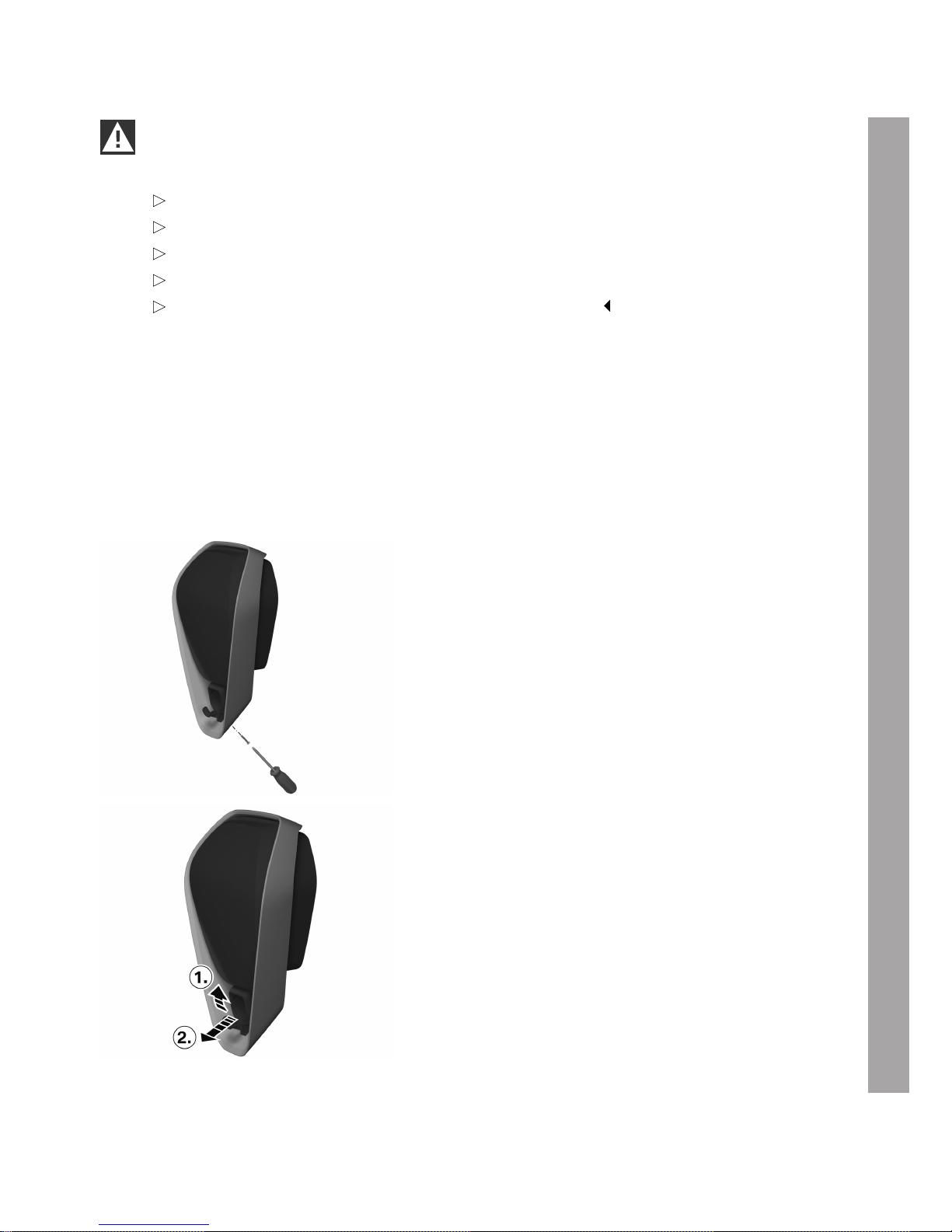
1. Undo the screw at the bottom of the design
frame using the PH2 cross head screwdriver.
2. Raise the front connector holder slightly 1 and
guide it out towards the front 2.
Page 14
14
Remove the housing cover
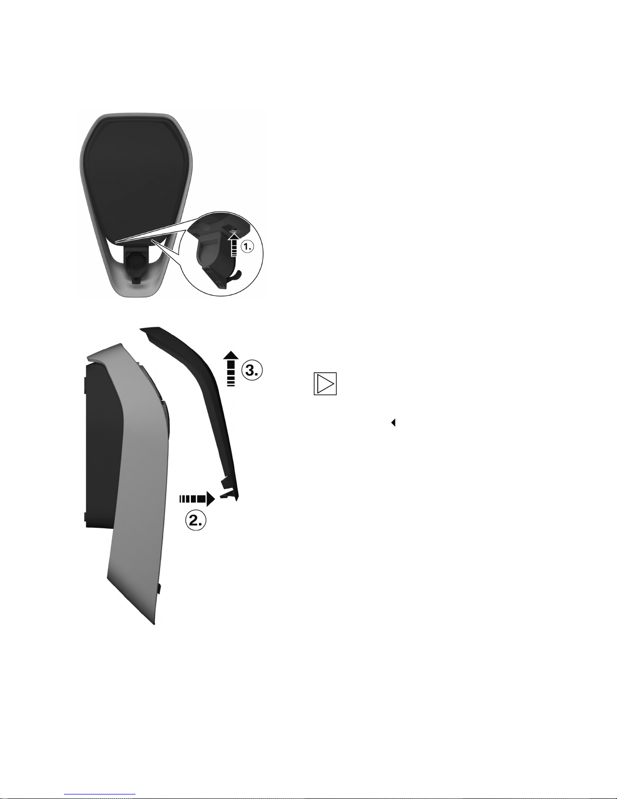
1. Press the two interlocks 1 for the housing
cover on the underside of the Wallbox
upwards.
The housing cover should then jump out
slightly at the bottom.
2. Swing the housing cover forwards a little on
the underside 2.
3. Then release the housing cover by raising it 3.
Note
Keep the housing cover carefully to prevent
it being scratched or suffering other
damage.
Page 15
EN
15
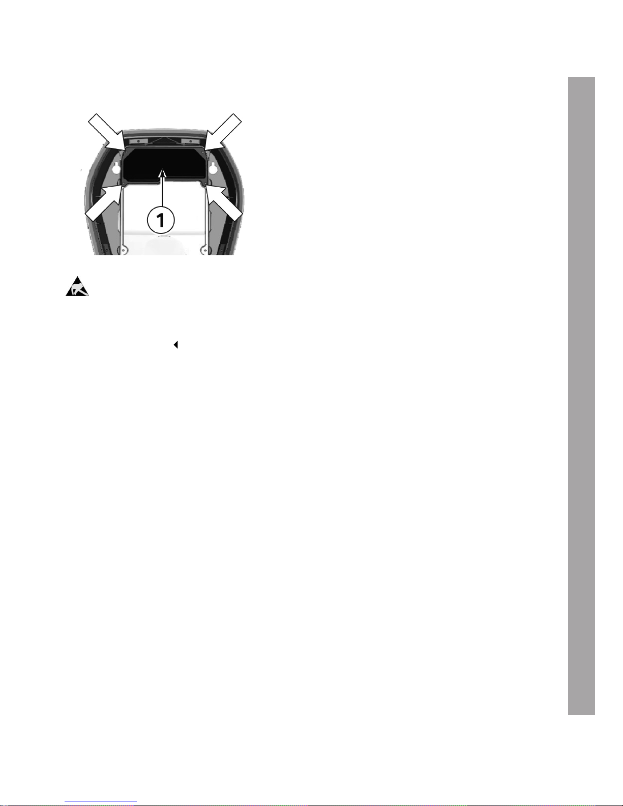
Remove the termination panel cover
1. Undo the four screws used to secure the
termination panel cover 1.
ESD
Danger of damage. Electronic components may be destroyed if touched.
Before handling modules, perform an electrical discharge process by touching a metallic
earthed object.
Page 16
16
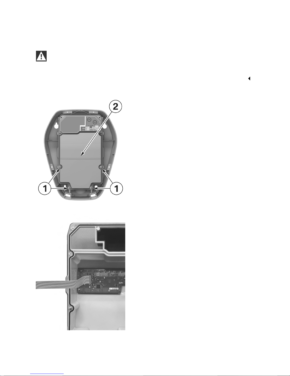
Remove the front part
IMPORTANT
Danger of damage.
The front part and the bottom of the housing are connected by a ribbon cable. Ensure that you
do not damage the ribbon table or its plug connectors by handling the front part with care.
1. Remove the four screws 1 in the front part 2
using a T25 Torx screwdriver.
2. Disconnect the ribbon cable from the circuit
board inside the front part and put the front
part to one side.
Page 17
EN
17
INSTALLATION
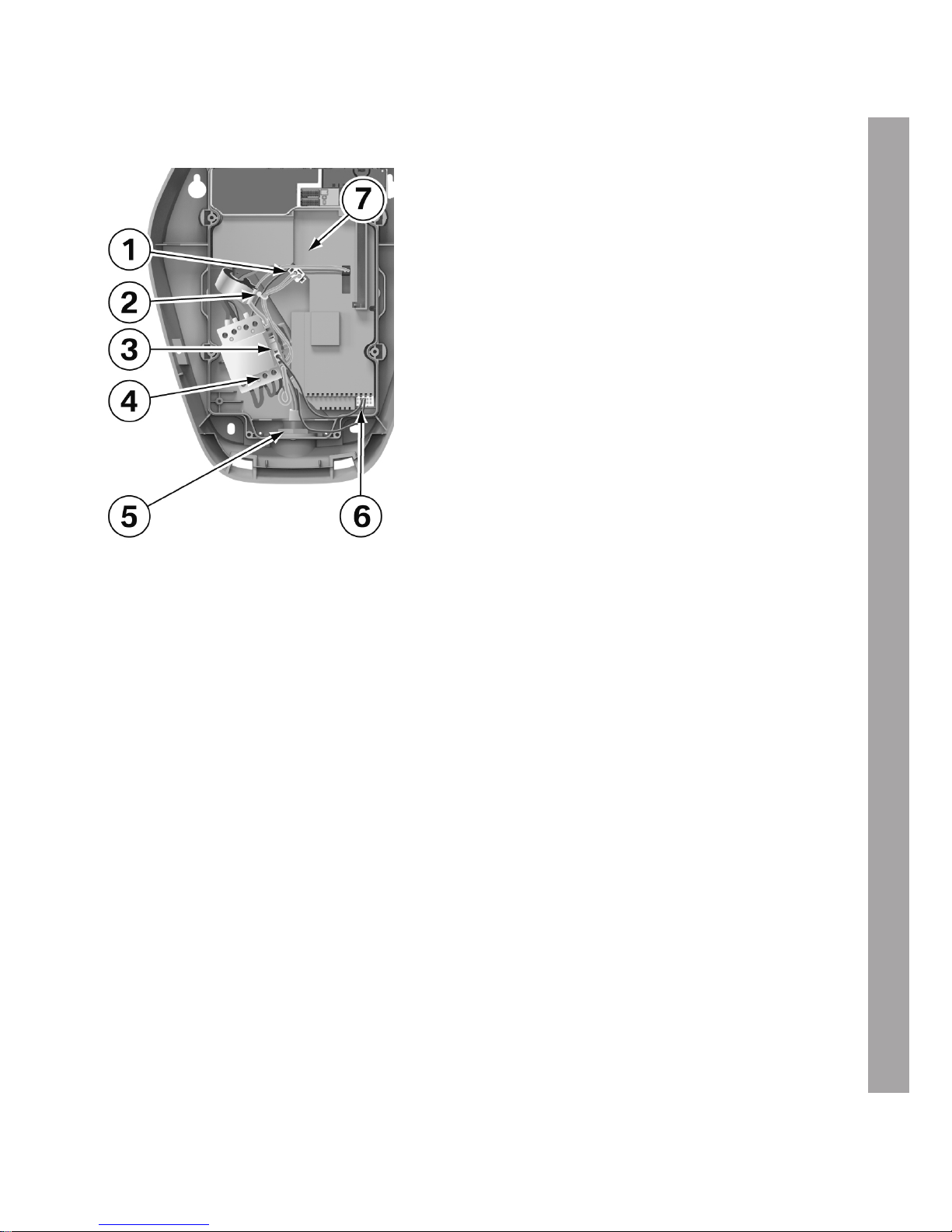
Overview
1 Switch feedback connector
2 Switch feedback cable tie
3 Earth terminal
4 Contactor terminals
5 Cable gland lock nut
6 Pilot cable connector
7 Electronics cover
Page 18
18
Disconnect the old charging cable
Note
Make a note of or photograph the assignment of all connected cables so that you can
reconnect them correctly after replacing the charging cable.
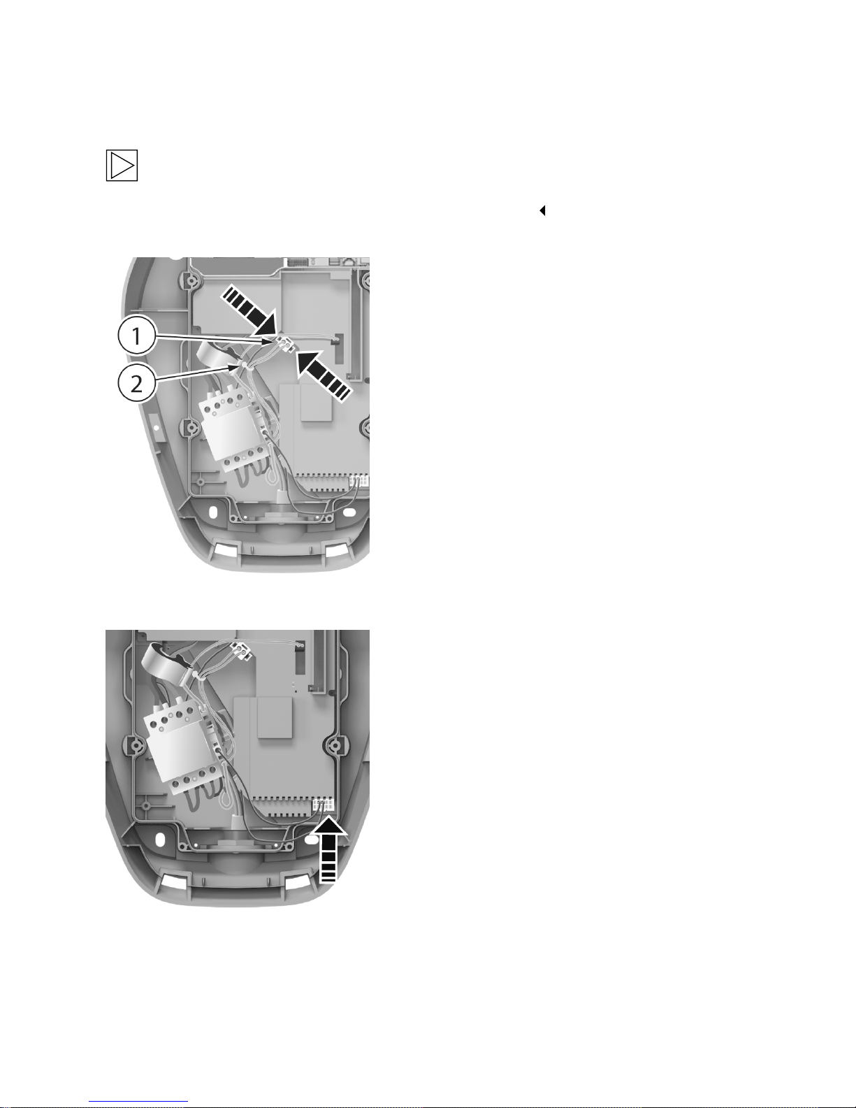
Disconnect the switch feedback (connector
at top right)
1. Remove the cable tie 2 using a side cutter.
2. Disconnect the connector 1 by pressing the
clips on the right and left together and pulling
out the connector.
Disconnect the pilot contact (connector at
bottom right)
3. Disconnect the connector for the pilot contact
by pressing the bottom clip with your index
finger and carefully pulling out the connector.
Page 19
EN
19
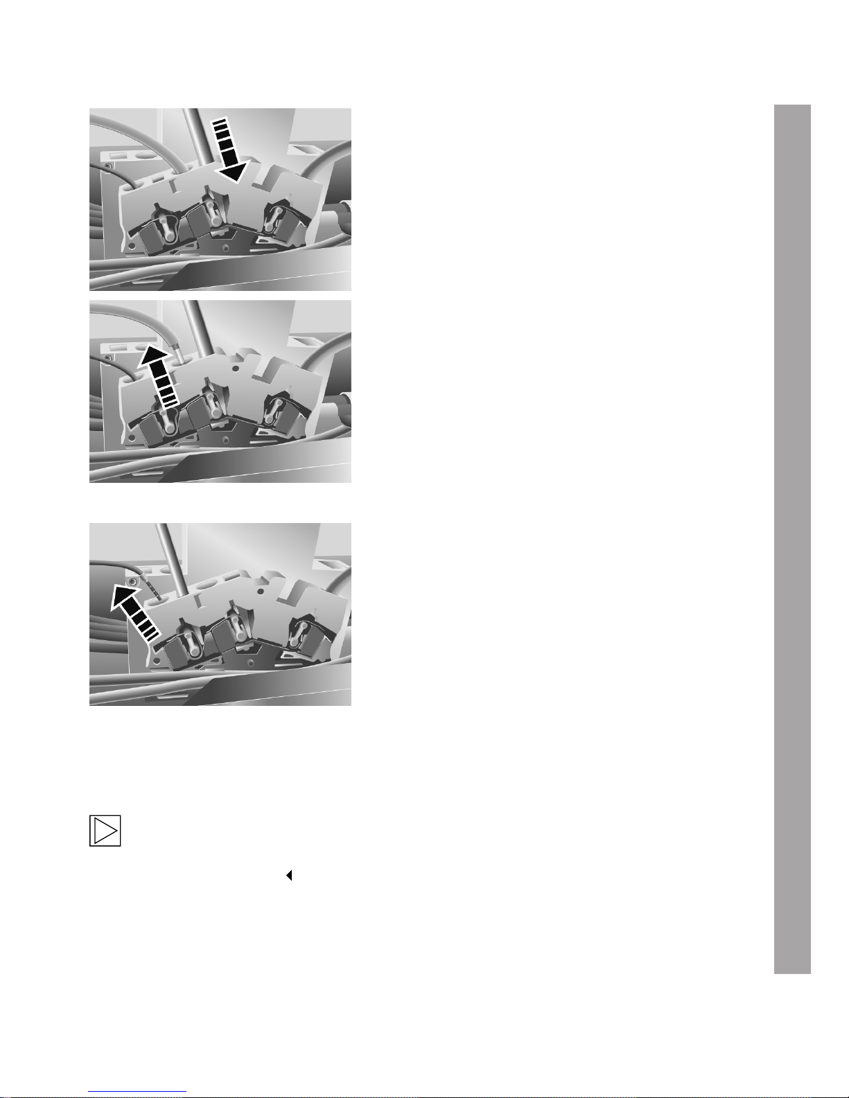
Disconnect the cable from the earth
terminal: Remove the charging cable's
earth conductor
4. Push a flat screwdriver (blade width 5.5 mm)
into the terminal as shown in the figure.
5. Press the flat screwdriver with moderate force
straight into the terminal until the contact
opens fully.
6. Pull the protective conductor out of the
terminal.
7. Pull the flat screwdriver out of the terminal.
Disconnect the cable from the earth
terminal: Remove the pilot contact's earth
conductor
8. Repeat steps 4-7 to disconnect the pilot
contact's earth conductor.
Disconnected the charging cable from the contactor
9. Disconnect the cores of the charging cable from the contactor (bottom row of terminals) using a
PZ2 cross head screw driver.
Note
Only disconnect those cables required to replace the charging cable. The switch contact A2
can remain connected.
Page 20
20
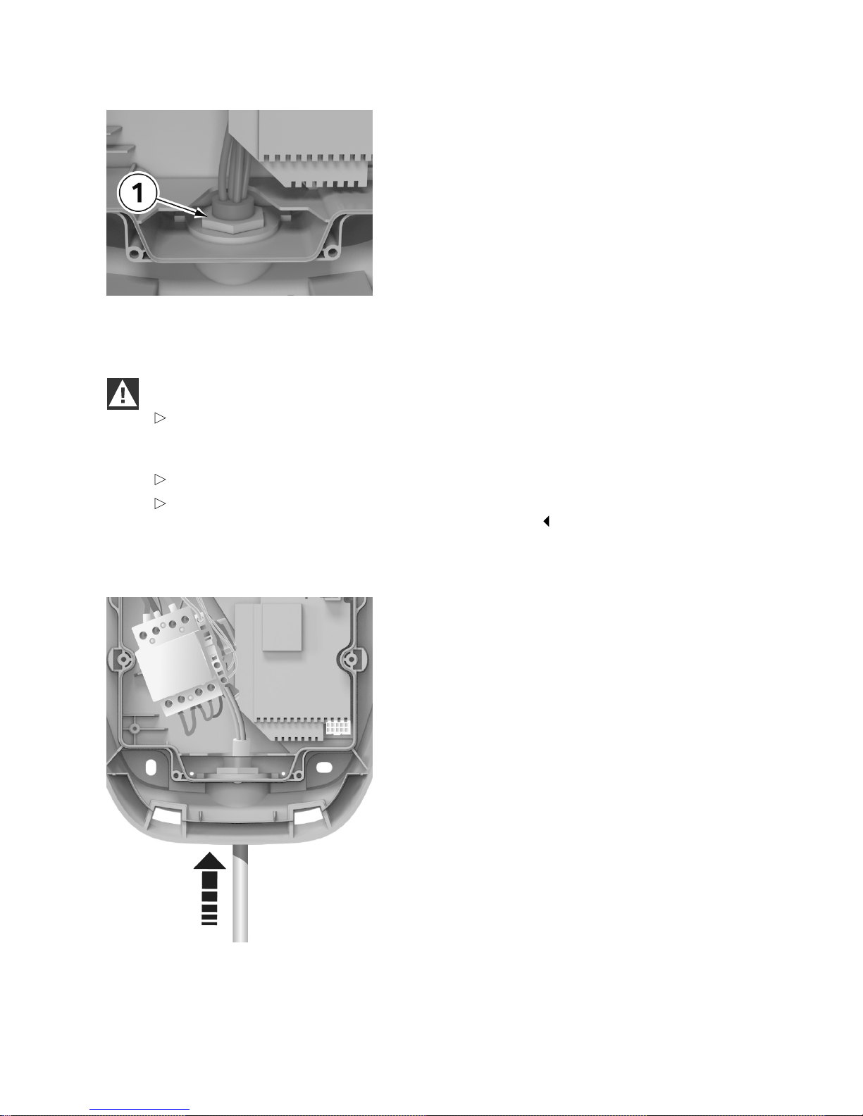
Remove the lock nut on the cable gland
10. Remove the lock nut 1 on the cable gland
using an open-ended spanner.
11. Pull the old charging cable downwards out of
the Wallbox.
Prepare the new charging cable
CAUTION
The design current for the charging cable must not be less than the design current for
the Wallbox. To check this, compare the figures on the model plate of the Wallbox with the
figures on the charging cable.
Check the spare part for possible signs of damage and ensure it is in perfect condition.
The cable gland on the new charging cable must not be opened. The charging cable can
be replaced by opening the lock nut inside the housing.
1. Remove the cable ties holding the new charging cable together.
2. Thread the new charging cable into the
Wallbox.
3. Secure the screw connection using the brass
nut in the package (torque: 4 Nm).
Page 21
EN
21
Connect the new charging cable
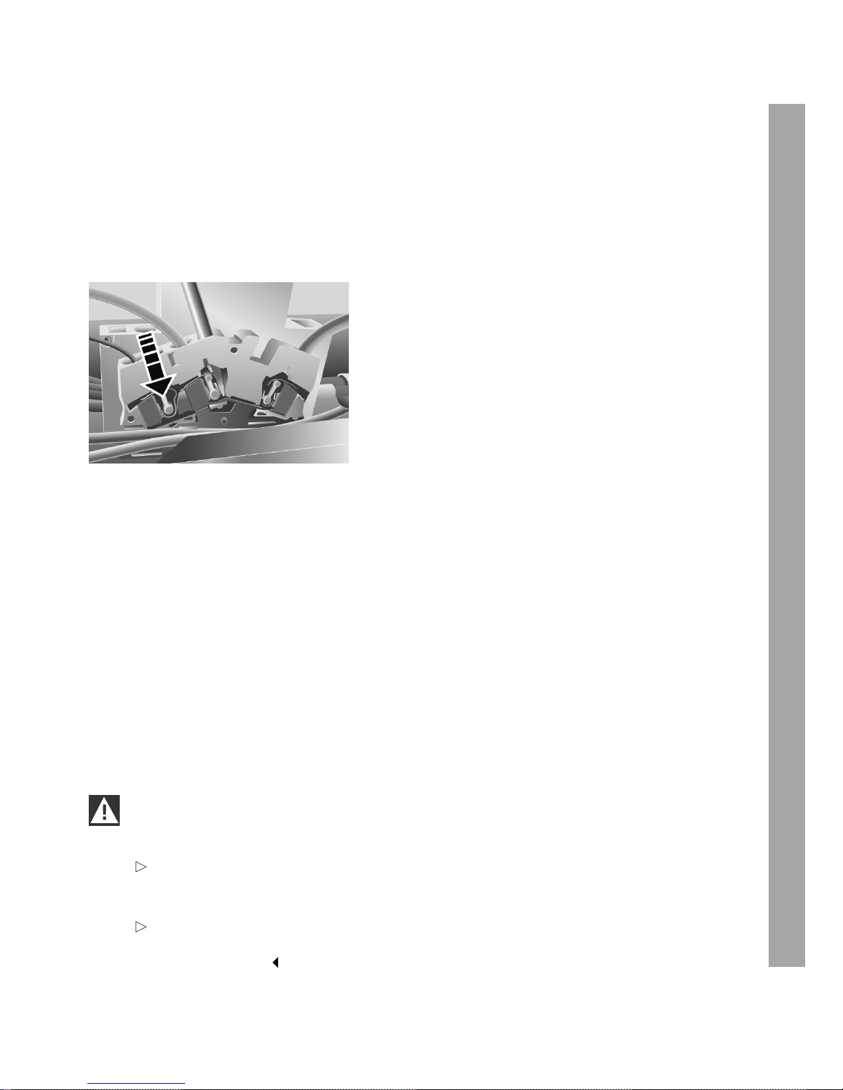
1. Connect the charging cable (phases and neutral conductor) to the contactor using a PZ2 cross
head screwdriver (torque: 2.5-3 Nm).
2. Connect the switch feedback connector and secure the cables as before using the cable ties
provided.
3. Connect the pilot connector.
Connect the charging cable's earth
conductor to the earth terminal
4. Press the flat screwdriver (blade width 5.5 mm)
with moderate force straight into the terminal
until the contact opens fully.
5. Push the protective conductor properly into the
terminal.
6. Pull the screwdriver out of the terminal.
Connect the pilot connector's earth conductor to the earth terminal
7. Repeat steps 4-6 to connect the pilot contact's earth conductor.
Final check
1. Check that L, N and PE have been connected correctly.
2. Remove any foreign material from inside the Wallbox.
3. Check that all screw and terminal connections are tight.
4. Check that all the cable glands that are not in use have been properly sealed with blind plugs or
blind glands.
Install the front part
IMPORTANT
Danger of damage.
Check the seal on the front part for dirt or defects. If the seal has obvious defects, the
Wallbox must not be started. In this case, have the action required for the repair or
replacement of the Wallbox carried out by the manufacturer.
Take care when fitting the front part to prevent crushing cables between the housing
halves. Pay particular attention to the pilot cable at the bottom right and the ribbon cable on
the outside right.
Page 22
22
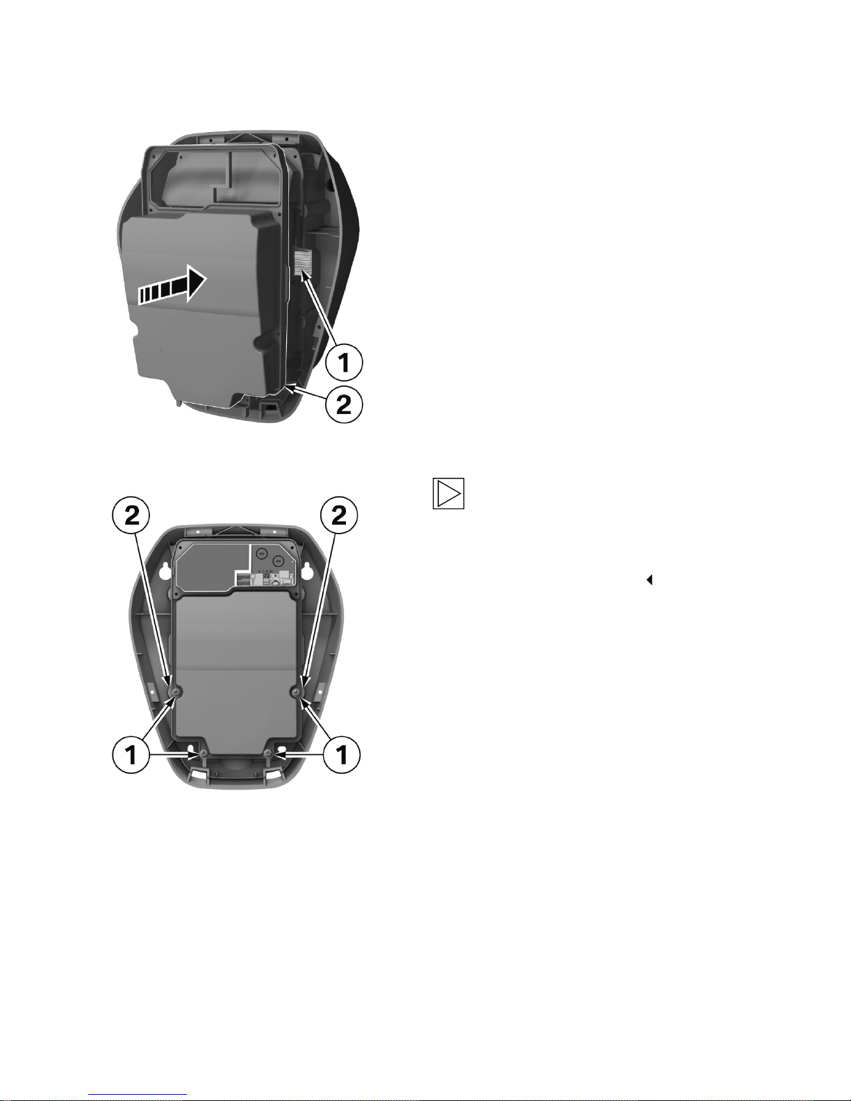
1. Take the front part in your hand.
2. Connect the connector on the ribbon cable 1
to the circuit board inside the front part.
3. Return the front part to its original position.
4. Tighten the four screws in the front part using
a T25 Torx screwdriver.
Note
Tighten the screws 1 until the housing
markings on the right and left 2 on the
termination panel cover are flush with the
housing (torque: 3.5 Nm).
Page 23
EN
23
COMMISSIONING & SAFETY TESTS
General commissioning procedure
Switch on the supply voltage. After the self-test, which is conducted automatically at the start, the
blue status LED (LED bar) must be lit after 15-20 seconds.
Conduct the specified initial tests to comply with local regulations and laws.
Commissioning mode/Self-test
The Wallbox can be set to a commissioning mode to help with the initial system tests. This conducts
a extended self-test on the device (contactor actuation, current measurement, etc.) and then displays
possible problems.
After the test has been successfully completed without a vehicle connected, the contactor will be
actuated for a limited period of time (around 10 minutes) to allow the initial tests to be completed. A
normal charging cycle is not possible in commissioning mode.
If the Wallbox is switched on in commissioning mode using the supply voltage, an error
(white-red-red-red) will be displayed for safety reasons to prevent accidental activation.
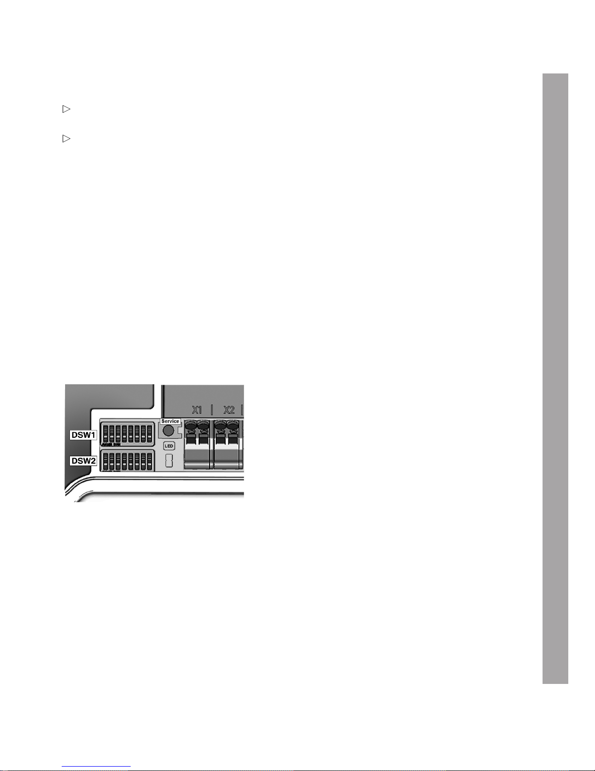
Enable commissioning mode
1. Set DIP switch DSW2.8 to ON.
1. Conduct a reset of the Wallbox. Press the Service button for 1second (signal tone) for this
purpose. Commissioning mode is now enabled and is indicated by the orange status LED being lit.
2. It is now possible for approximately 10 minutes to contact with the measuring instrument using
standard test clips (for example Astaco® test clips from BEHA) and conduct the required safety
tests. After this time the contactor is disabled and the Wallbox switched off.
Disable commissioning mode
1. Set DIP switch DSW2.8 to OFF again.
2. Conduct a reset of the Wallbox. Press the den Service button for 1second (signal tone) for
this purpose or switch the supply voltage off and on again. The Wallbox will power up in operating
mode and is then ready for use.
Page 24

24
Safety tests
Before commissioning the device, check the effectiveness of the system's protective measure(s) in
accordance with national regulations such as ÖVE/ÖNORM E8001-6-61, DIN VDE 0100-600.
Electrical systems or devices must be tested by the installer of the system or device before being used
for the first time. This also applies to the extension or modification of existing systems or electrical
devices. However, we must expressly point out that all regulations for the protective measures must be
observed.
Among others, the following points must be taken into account:
1. The tests: The continuity of the connections of the protective conductor, insulation resistance,
residual-current-operated circuit breaker, trip current and trip time must be found for the extended
or modified part.
2. The measuring instruments used must comply with national regulations, for example
DIN EN 60557 (VDE 0413) "Electrical safety in low voltage networks up to AC 1000 V and DC
1500 V".
3. The measurement results must be documented. A test log for the test must be prepared and
archived.
Page 25
EN
25
CONCLUDING WORK
Install the terminal cover
Note
If you did not remove the terminal cover during the installation work, continue with section
Install the termination panel cover.
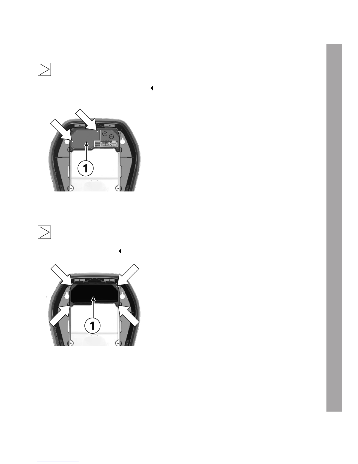
1. Fit the terminal cover 1 again using the two
fastening screws (torque: 1.5 Nm).
Install the termination panel cover
Note
The Wallbox must not be switched on permanently if this cover is missing or damaged. Do not
use alternative covers.
Fastening screws
1. Insert the termination panel cover 1 again.
2. Install the termination panel cover again using
the four screws.
Page 26
26
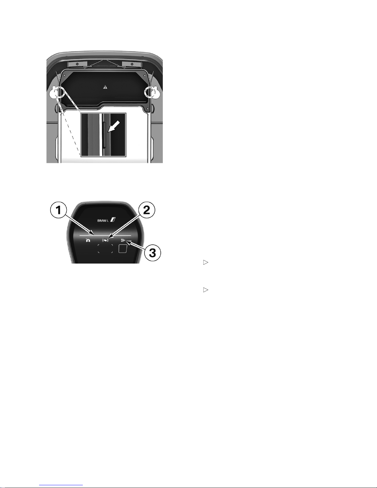
Housing marking
1. Tighten the four screws until the housing
markings on the right and left on the
termination panel cover are flush with the
housing.
2. The termination panel cover must correctly
seal the housing. Increased force is required for
the self-tapping screws: 3.5Nm.
Test the function
1. Reconnect the voltage supply to the Wallbox.
To do this, switch the circuit breaker for the
building installation back on.
2. After the self-test, which is conducted
automatically at the start, the blue
status LED (LED bar) 1 must be lit after
15-20 seconds.
In the event that the RFID authorisation
is active, the RFID status indicator 2 will
pulse instead.
If your Wallbox has a communication
module (Wallbox Connect), the
indicator for charging mode 3 must light
up after 5 minutes.
3. If possible, perform a test charge using an
electric car.
Page 27
EN
27
Affix warranty seals
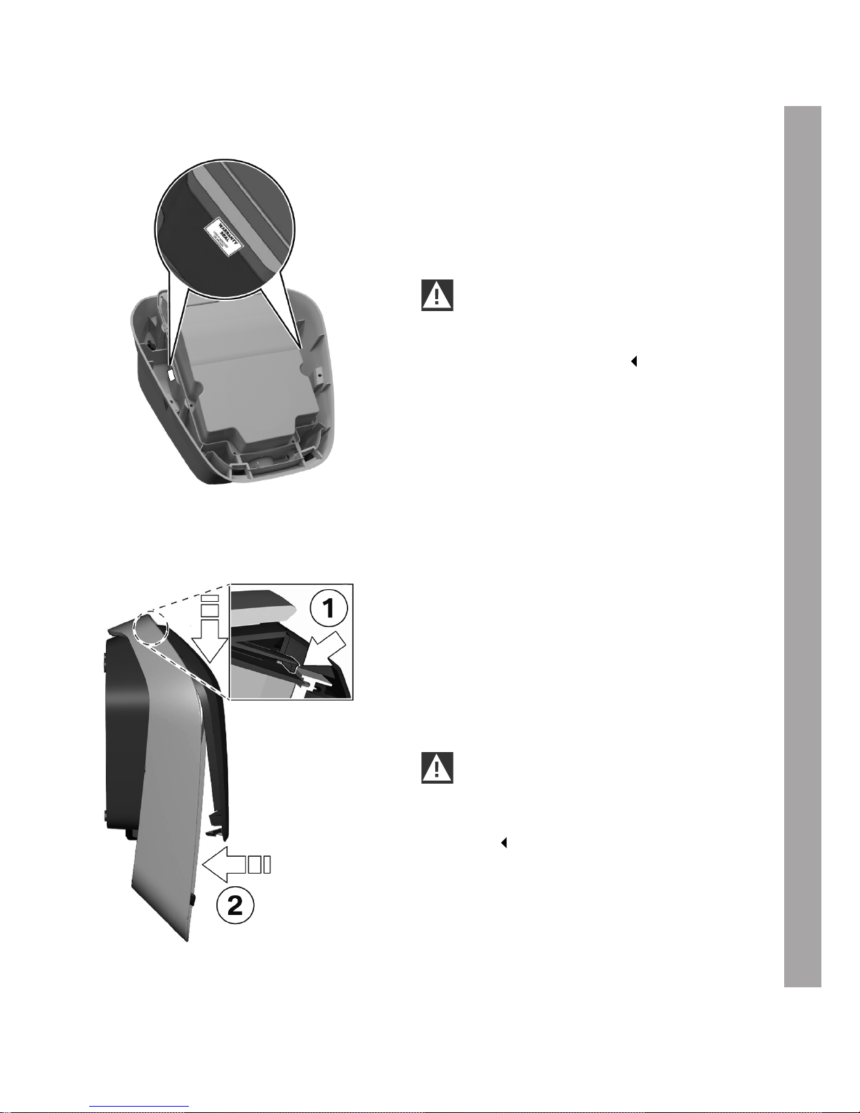
1. Clean the surfaces on the left and right on the
Wallbox to which the warranty seals are to be
affixed, see illustration to the left. The area
must be clean and free from dust or grease.
2. Affix the supplied warranty seals as shown to
the right and left.
IMPORTANT
Use a damp cloth or a cleaning product
suitable for plastics, such as isopropanol, to
clean the bonding areas.
Install the housing cover
Attach the housing cover
1. Attach the housing cover at the top and
ensured that the hooks on the housing cover
are correctly attached 1.
2. Press the cover downwards and then push the
housing cover 2 backwards.
The housing cover must slide into the bottom
guides without any major resistance.
IMPORTANT
Ensure that the housing cover is correctly
positioned in the housing guide on all sides.
The most only be a minimum uniform
gap.
Page 28
28
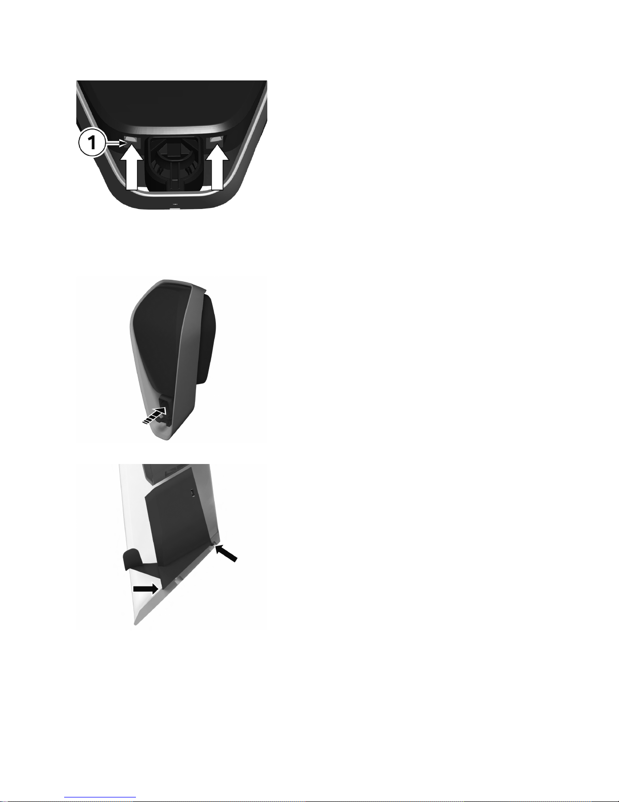
Interlocks
3. Press the bottom section of the housing cover
on to the Wallbox until the interlocks 1 fully
engage.
Install the connector holder
1. Insert the connector holder.
2. Position the connector holder as shown in the
figure.
Page 29
EN
29
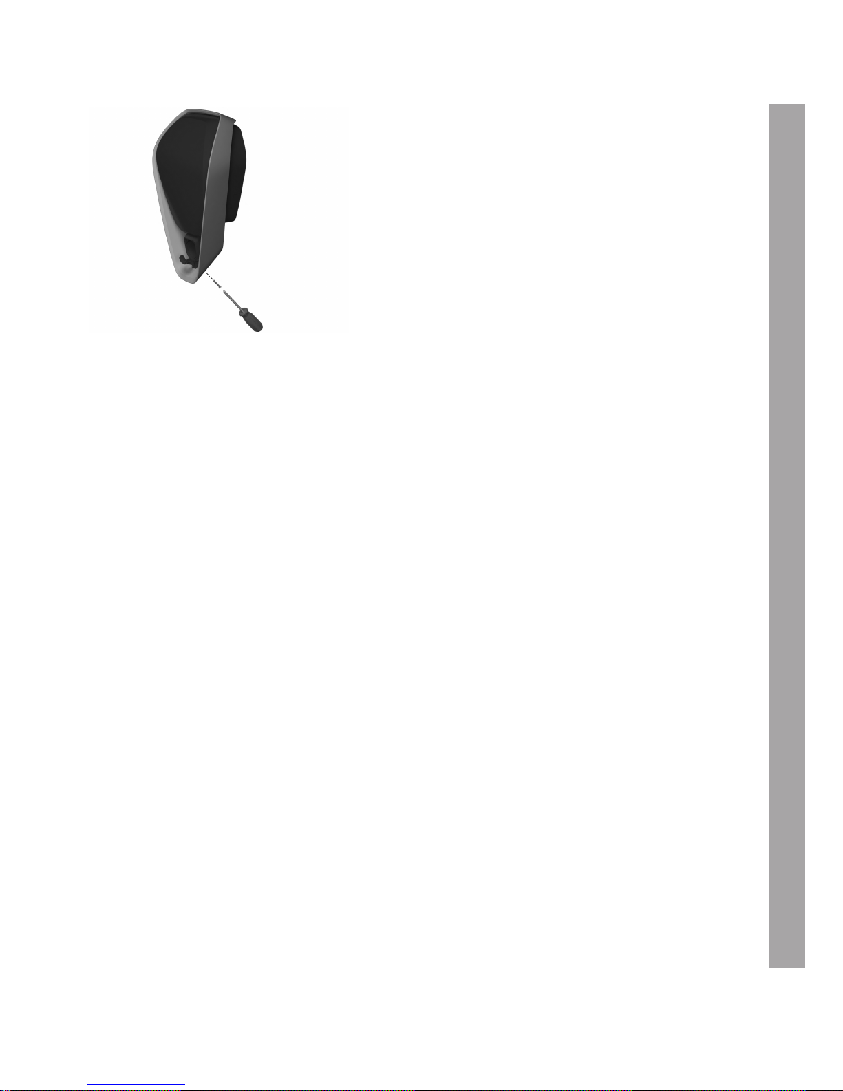
3. Screw the connector holder into position using
the screw.
Page 30

30
ADDITIONAL INFORMATION
Other functions and settings
Information about of the functions and settings is provided in the Wallbox installation manual or
operating manual.
Manuals, software, downloads
http://www.bmwgroup.com/360electric/index.html.
Page 31
EN
31
DISPOSAL
After correctly decommissioning the device, please have it disposed of by the service
department in compliance with current waste disposal regulations.
Disposal information
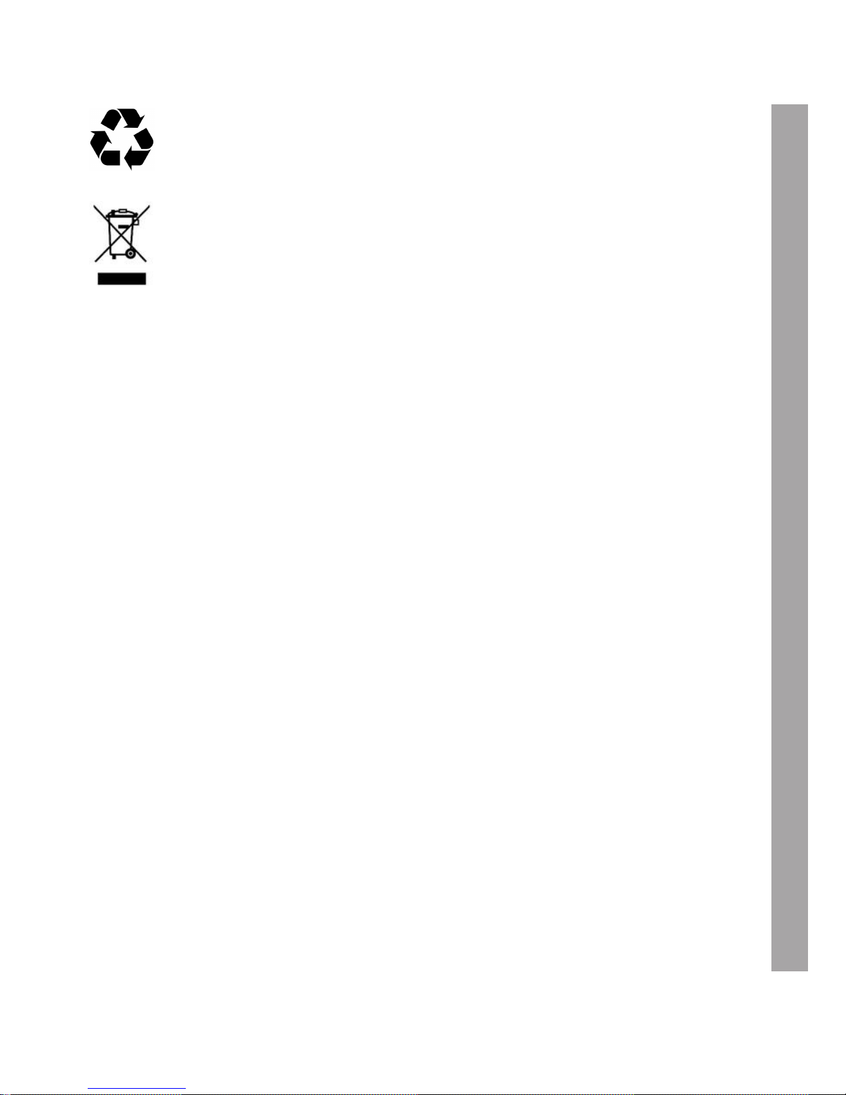
The symbol of the waste bin with a line through it indicates that electrical and
electronic devices including accessories must be disposed of separately from general
household waste. There are instructions on the product, in the instructions for use or
on the packaging.
The materials can be recycled as shown by their labelling. You can make a significant
contribution to protecting our environment by reusing, recycling the material or other
forms of recycling of end-of-life devices.
Page 32

32
INDEX
C
Commissioning.............................................................................................................................................................. 23
Commissioning mode / Self-test.............................................................................................................................. 23
Connect the new charging cable............................................................................................................................. 21
D
Disconnect the old charging cable.......................................................................................................................... 18
Disposal............................................................................................................................................................................ 31
I
Installation........................................................................................................................................................................ 17
Install the connector holder....................................................................................................................................... 28
Install the front part...................................................................................................................................................... 21
Install the housing cover............................................................................................................................................. 27
Install the terminal cover............................................................................................................................................. 25
Install the termination panel cover........................................................................................................................... 25
L
Legal information............................................................................................................................................................. 7
List of tools..................................................................................................................................................................... 12
P
Package............................................................................................................................................................................ 10
Prepare the new charging cable.............................................................................................................................. 20
R
Remove the connector holder.................................................................................................................................. 13
Remove the front part................................................................................................................................................. 16
Remove the housing cover........................................................................................................................................ 14
Remove the termination panel cover...................................................................................................................... 15
S
Safety information........................................................................................................................................................... 9
Safety tests..................................................................................................................................................................... 24
Switch off the voltage supply.................................................................................................................................... 12
T
Test the function........................................................................................................................................................... 26
W
Warranty........................................................................................................................................................................... 11
Warranty seals................................................................................................................................................................ 27
Page 33

Page 34

Page 35

Page 36
Mehr über BMW
www.bmw.de
www.bmw.com
Freude am Fahren
102790
IA Ladekabel für BMW i Wallbox EUR 1.0
 Loading...