

Page 1

Repair Manual
F 650 CS
BMW Motorrad
After Sales
Page 2

Issued by © BMW Motorrad
After Sales
UX-VS-2
All rights reserved. Not to be reprinted, translated or duplicated either wholly or in part without prior written
permission.
Errors and omissions excepted; subject to technical amendment.
Printed in Germany 06/01
Page 3
Introduction
This Repair Manual will help you to perform all the main maintenance and repair work correctly and efficiently. If it is consulted regularly by workshop personnel it will form a useful addition to the theoretical and
practical knowledge acquired at the BMW Training Centre. It is a contribution toward achieving even higher
Service quality.
A new issue of this repair manual will be published if amendments or additions (supplements) are needed.
All information in both text and illustrations refers to motorcycles in standard condition or with genuine
BMW accessories installed, and not to motorcycles which have been modified in any way to depart from
the manufacturer’s specification.
The Repair Manual is structured in the logical sequence of the work to be performed: Removal, Disas-
•
sembling, Repair, Assembly, Installation.
The entire contents are divided into individual chapters, corresponding to the Construction Groups.
•
11 . 10
Chapter Page number within chapter
If a reference is needed to a different page or chapter, an arrow symbol is shown followed by the chapter
and page numbers, e. g. (
Work to be performed during an Inspection is described in Group “00”. The various inspection routines
•
are numbered I, II, III and IV. This numbering is repeated in the work descriptions which follow, so that
work can take place without interruption.
a 12.5).
Use of the BMW special tools needed for certain tasks is described in the work instructions.
•
If the need arises, repair instructions are also issued in the form of Service Information. This information is
of course incorporated into the next issue of the Repair Manual. We also recommend, as an additional
source of information, the Electronic Parts Catalogue (ETK), which contains clear and easy-to-follow illustrations.
If the work described here is restricted to a particular equipment specification, for instance if a specific optional extra (OE) is fitted, this is stated in square brackets at the start of the item concerned, e.g. [Heated
handlebar grips].
Please refer to the following pages as well for a description of other symbols used and how to work with
them.
BMW Motorrad
After Sales
Issued by BMW Motorrad
After Sales
UX-VS-2
D-80788 München
All rights reserved. Not to be reprinted, translated or duplicated either wholly or in part without prior written
permission.
Errors and omissions excepted; subject to technical amendment.
Produced in Germany
Page 4

Use
Each chapter starts with the list of contents.
The list of contents is followed by the technical data table.
Key to symbols
In this Repair Manual for the F 650 CS model, the following symbols are used; their meanings are explained
in the table.
Special instructions aimed at improving the work procedures
L Note:
Special information on operating and inspecting the motorcycle as well as maintenance and adjustment
procedures.
e Attention:
Instructions and precautions specifically intended to prevent damage to the motorcycle. Failure to comply
with them could invalidate the warranty.
d Warning:
This symbol stands for precautions and measures which are essential in order to protect the rider or other
persons from possibly severe or fatal injury.
Contents
The titles of the tasks described in this chapter............. complete with page numbers
Activities
Activities
•
The bullet symbol indicates work steps that are described in greater detail under another headline
•
– Preceding activities
– A line indicates work steps that are described in greater detail under another headline or in another
chapter
The term "remove" means that:
the fastener (e.g. screw) must be backed off completely and removed
or
a component (e.g. injection rail) has to be removed to the extent that components behind it (e.g. throttle
valve rail) are rendered accessible
The term "loosen" or "slacken" means that:
the fastener (e.g. screw) must be backed off, but not removed
X Tightening torque:
Values are stated if they differ from DIN EN 24 014 or DIN 912 ISO industrial standards.
Page 5

BMW Motorrad
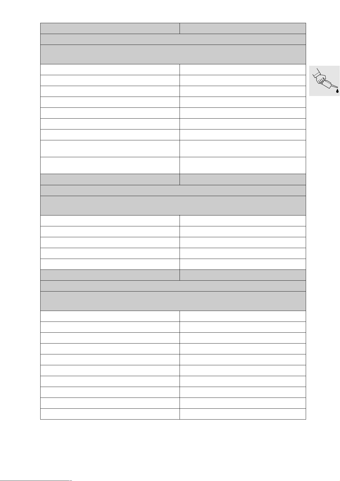
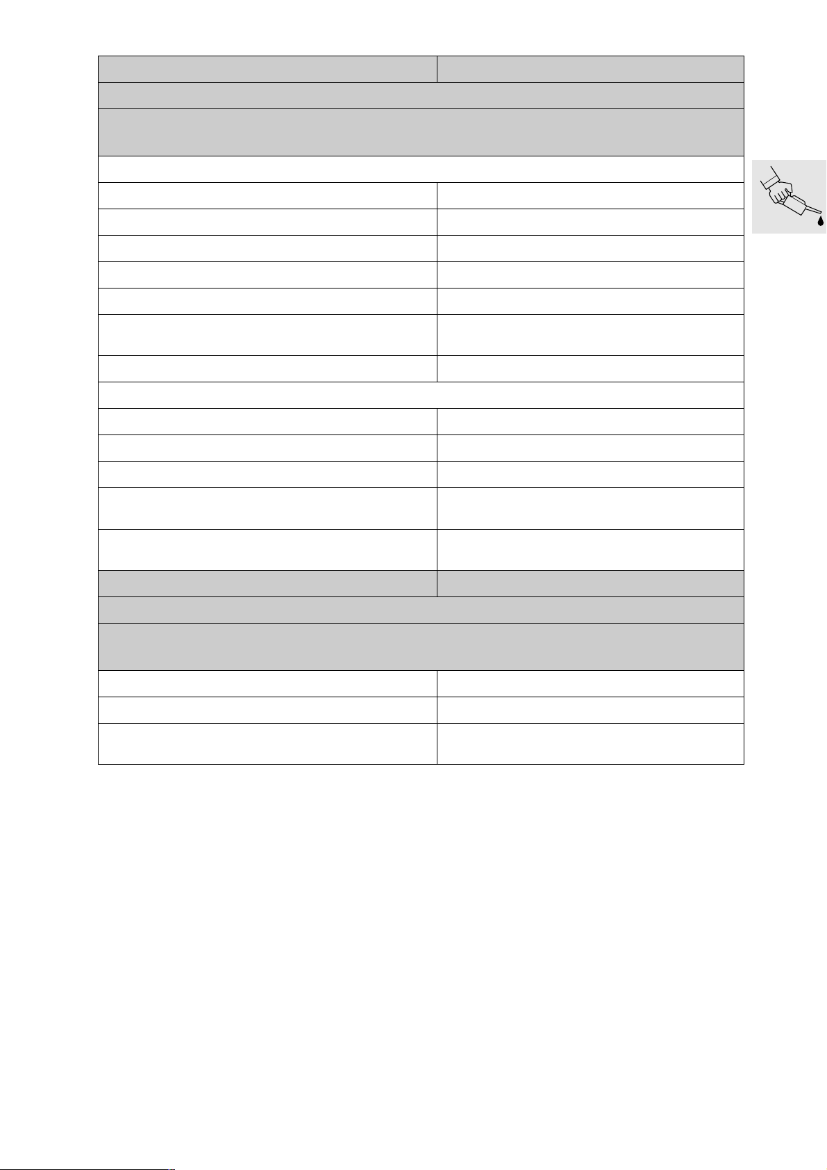
Maintenance schedule
F 650 CS
Customer Licence No. Mileage
Job Order No. Date Mechanic’s signature
Read the fault code memory with the BMW MoDiTeC
Change the engine oil [engine only] while at regular operating temperature
and replace the oil filter element
Change the engine oil [engine and oil tank] while at regular operating temperature
and replace the oil filter element
if motorcycle is used only for short journeys or at outside temperatures below 0°C (32°F): every
3 months or at the latest after 3,000 km (1,800 miles)
Clean oil strainer in frame
once only at 10,000 km/6,000 miles
Check the coolant and restore to correct level if necessary
Grease rubber grommets for cover insert
Replace the coolant
every 2 years
Check valve clearances, adjust if necessary
Replace the spark plug
Drain the outlet hose from the air filter box
Replace intake air filter
If motorcycle is operated in very dirty or dusty conditions, clean or replace the intake air filter every
10,000 km (6,000 miles); check every 3,000 km (1,800 miles)
Replace fuel filter
every 40,000 km (24,000 miles)
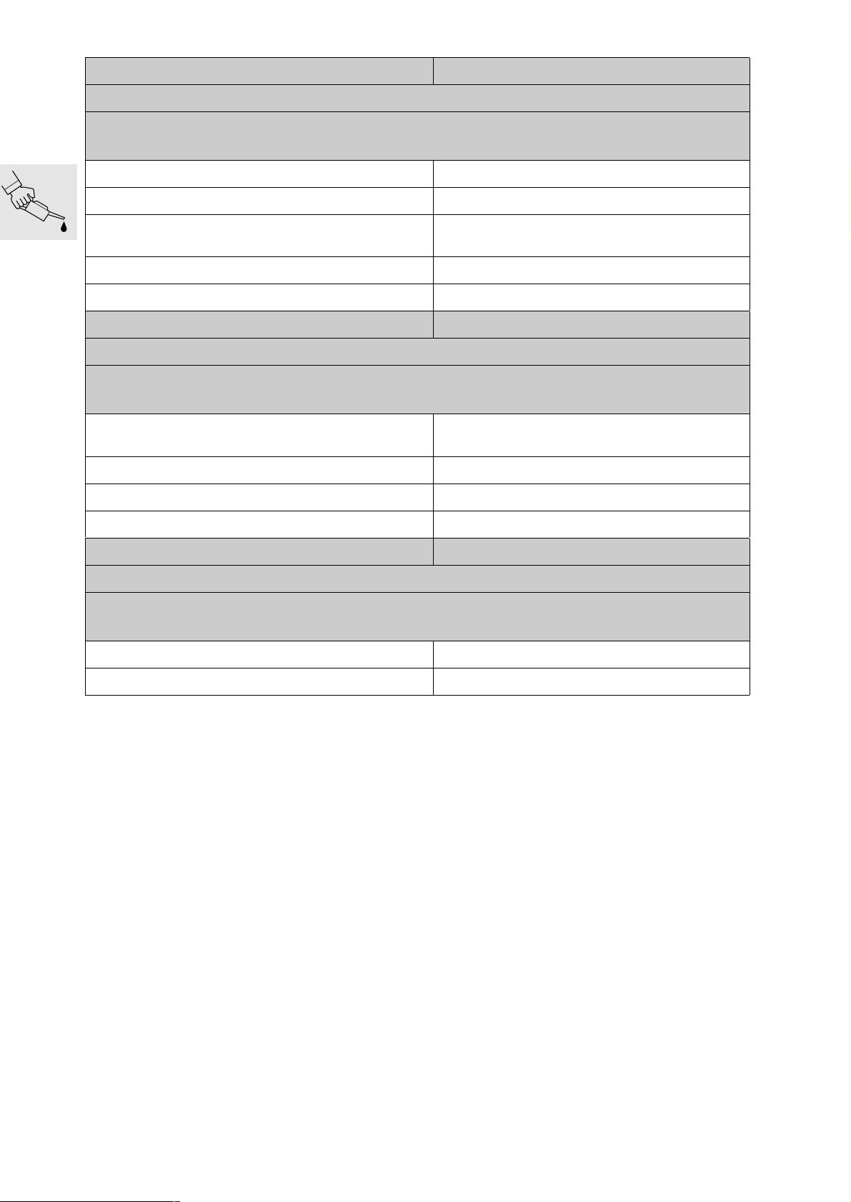
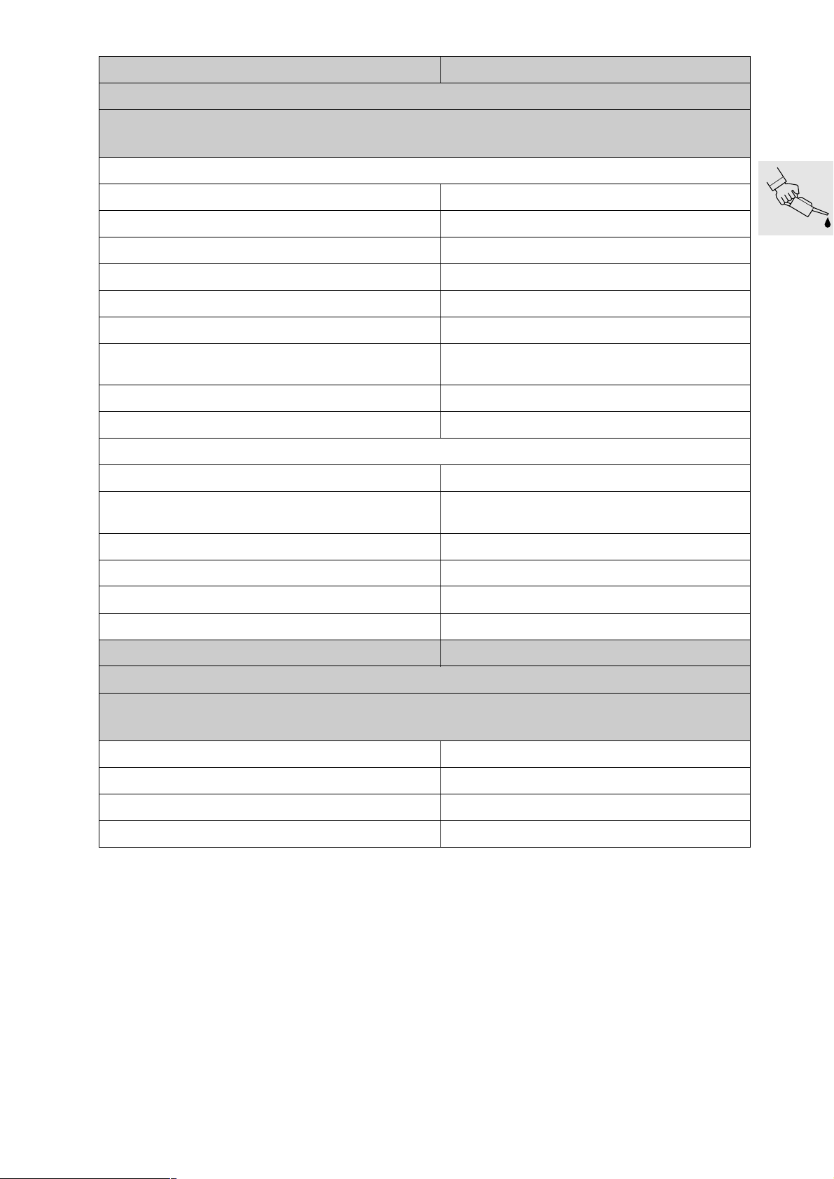
Check clutch play, adjust if necessary
Examine brake pads and discs for wear, replace if necessary
Check front/rear circuit brake fluid
Check for operation of brake system and freedom from leaks; repair/replace if necessary
Renew brake fluid at least once a year
[ABS] Replace the primary front/rear brake master cylinder cup
every 40,000 km (24,000 miles)
Replace toothed belt
Check toothed belt and sprocket, replace if necessary
Check belt tension, adjust if necessary
Check battery acid level, add distilled water if necessary
Clean and grease the battery terminals, if necessary
Check steering head bearings and adjust *) or replace if necessary
Grease the side stand
Using a torque wrench, check that the screws and nuts of the engine mounts, manifold fastener, the frame threaded fasteners, the rear-frame threaded fasteners, and the eccentric
clamp are tightened to specified torque
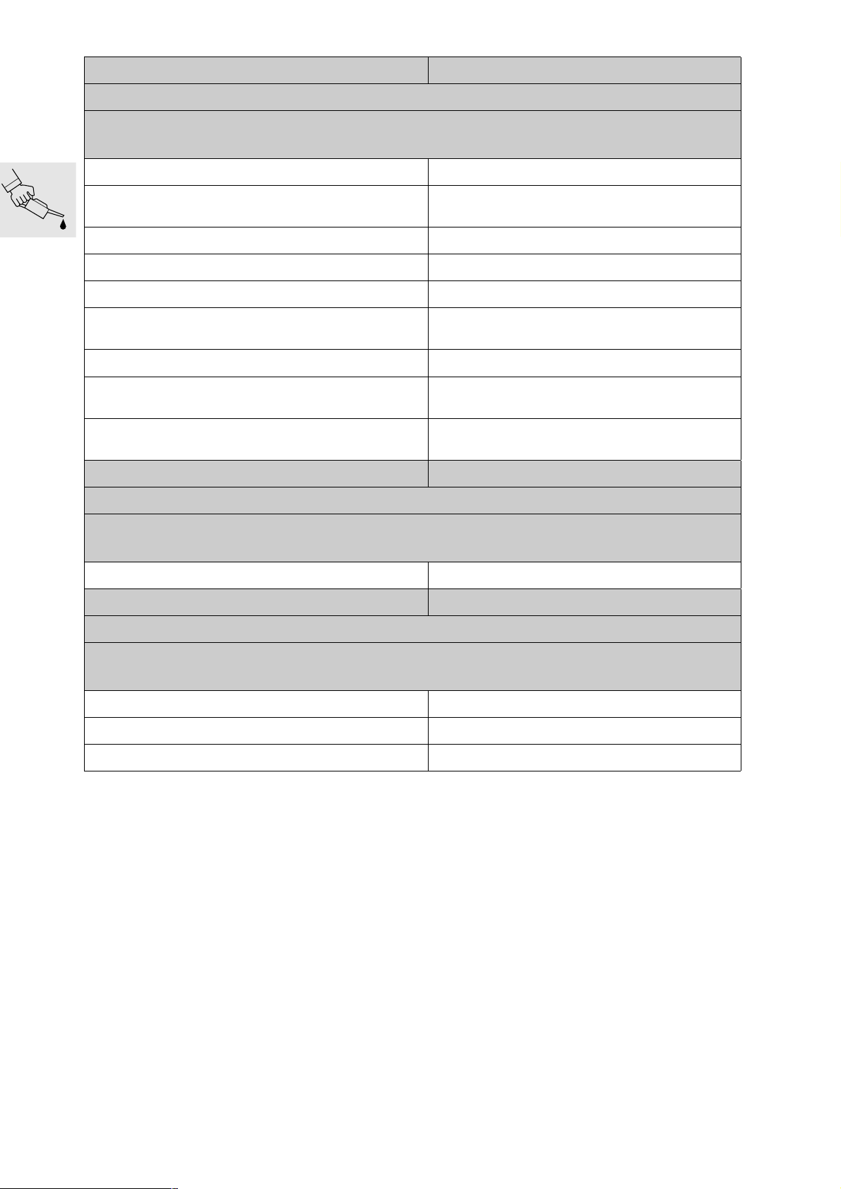
Final inspection with road safety and functional check:
– Clutch, gearshift
– Steering
– Front and rear brakes
– Side stand contact switch
– Condition of tyres and wheels, tyre pressures
– Lights and signalling equipment, indicator and warning lights, instruments
– Optional equipment
– Test ride, if necessary
*) Write up on separate invoice; Not part of standard service procedure
*)
*)
*)
*)
*)
*)
*)
BMW Inspection
at 1,000 km/600 miles
BMW Maintenance
Service every
10,000 km/6,000 miles
BMW Inspection
every 20,000 km/
12,0 0 0 miles
BMW
Annual Service
*)
UX-VS-2, 07.2001
BMW recommends Castrol
Page 6
BMW Motorrad
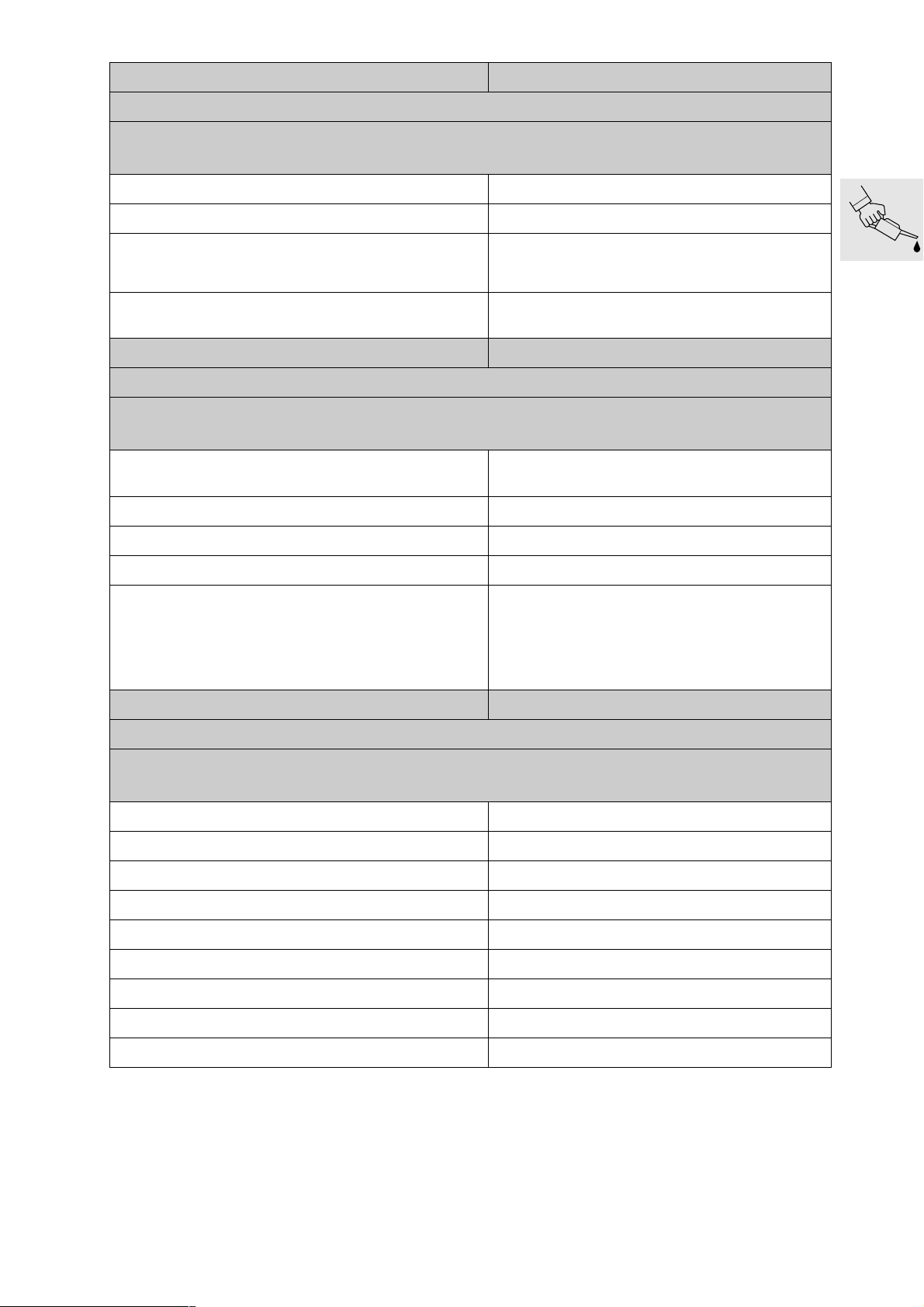
Pre-delivery check
F 650 CS
Customer Licence No.
Job Order No. Mechanic’s signature
Check the shipping pallet for damage
Unpack the motorcycle
Inspect motorcycle for damage
Check complete specification delivery:
– tools
– handbooks and documents
– keys
– optional extras
Motorcycle complete
BMW
Pre-delivery check
Battery:
– remove
– add battery acid
– charge
– grease the terminal posts
– re-install (mark date)
Check tyre pressure
Fuel the motorcycle
Safety/operating check as final inspection:
– Oil inspection
– Clutch, gearshift
– Steering
– Hand brakes and foot brakes
– Check lights and signalling equipment, warning and indicator lights, instruments, ABS
– Test ride, if necessary
Confirm delivery inspection in “Maintenance Booklet“
Final cleaning
Vehicle delivered on:
UX-VS-2, 07.2001
BMW recommends Castrol
Page 7

BMW Motorrad
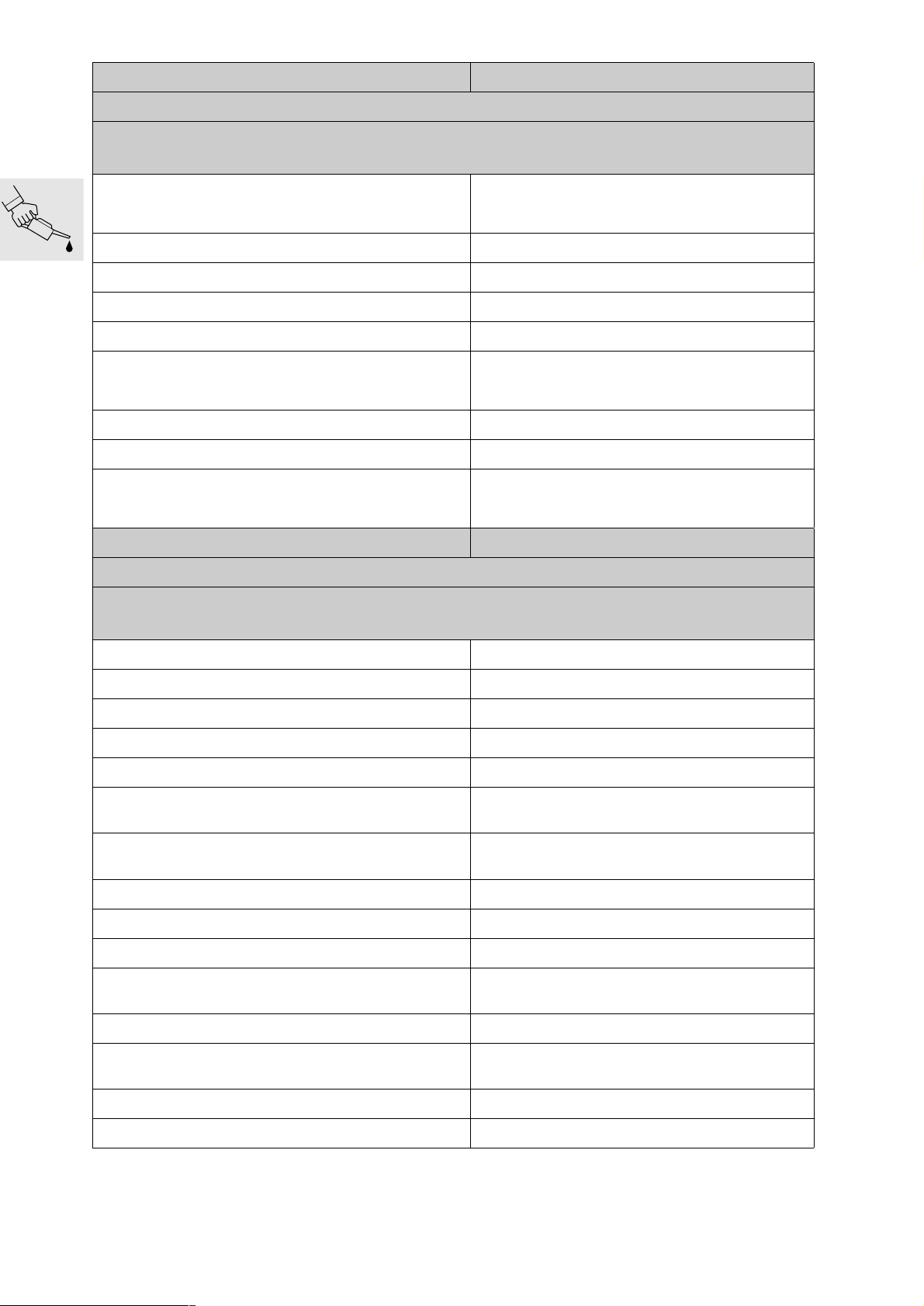
Service data
F 650 CS
Item Desired value Units / Specifications
Oil capacities
Engine (incl. filter) 0.5 (0.88/0.53)
Engine (incl. filter) and oil tank 2.5 (4.4/2.64)
Coolant
Cooling system 1.3 (2.29/1.37) Litres (Imp. pints/US quarts)
Reservoir 0.1 (0.18/0.11) Litres (Imp. pints/US quarts)
Brake Fluid DOT 4
Valve clearance
Inlet 0.03-0.11 (0.0012-0.004) mm (in)
Exhaust 0.25-0.33 (0.010-0.013) mm (in)
Spark plugs NGK DR8 EB
Electrode gap 0.6...0.7 (0.02...0.03) mm (in)
Engine idle speed 1,400 rpm
Clutch cable play
Cable at grip 1.0 - 2.0 (0.004 - 0.008) mm (in)
Tyre pressure
Solo front/rear 2.2/2.5 (31.91/36.26) bar (psi)
fully loaded front/rear 2.2/2.5 (31.91/36.26) bar (psi)
Tightening torques
Engine oil drain plug 40 Nm
Oil filter cover 10 Nm
Drain plug, on-frame oil tank 21 Nm
Oil lines to frame 42 Nm
Oil strainer to frame 80 Nm
Water pump drain screw 10 Nm
Vent screw 12 Nm
Expansion tank to radiator 9 Nm
Cylinder head cover 10 Nm
Spark plugs 20 Nm
Camshaft bearing cap 10 Nm
Chain guide 10 Nm (Loctite 243)
Fuel filter to stowage-compartment frame 9 Nm
Intake air pipe to intake air silencer 9 Nm
Suspension strut to angled lever 41 Nm
Eccentric clamp Initial tightening 10
Brake caliper to swinging arm 21 Nm
Struts to swinging arm 41 Nm
Swinging-fork pivot axle 100 Nm
Adjusting screw steering head bearing 25
Clamp screw for fork bridge steering head 23 Nm
Engine to frame at rear 50 Nm
Cylinder head to frame 41 Nm
Cylinder head to frame, locknut 100 Nm
Engine shell to engine 55 Nm
Engine shell to engine, bottom, with bottom truss 55 Nm
Engine shell to bracing tube 24 Nm
Rear frame to main frame 24 Nm (Loctite 2701)
Exhaust manifold to cylinder head 20 Nm
Silencer to exhaust manifold 55 Nm
50%
50%
21
Back off through
angle of rotation 60
Litres (Imp. pints/US quarts)
Specification: see latest
Service Information
Litres (Imp. pints/US quarts)
Specification: see latest
Service Information
Water
Anti-freeze
protection to –25 °C
measured cold (max. 35 °C/95 °F)
tyres cold
Nm
Nm
Nm
°
UX-VS-2, 07.2001
BMW recommends Castrol
Page 8

Contents
<< Back
Group / Chapter
00 Tightening torques, Operating fluids
00 Pre-delivery check
00 Maintenance
11 Engine
12 Engine electrics
13 Fuel preparation and control
16 Fuel tank and lines
17 Radiator
18 Exhaust system
21 Clutch
23 Gearbox
27 Chain/belt drive
W
M
B
31 Front forks
>> Continuation
Page 9
Group / Chapter
32 Steering
33 Rear wheel drive
34 Brakes
36 Wheels and tyres
46 Frame
>> Continuation
51 Equipment
61 General electrical equipment
62 Instruments
63 Lights
<< Back
Page 10

00
00 Tightening torques,
Operating fluids
Contents Page
Tightening torques ......................................................................................................................3
11 Engine ...........................................................................................................................................3
12 Engine electrics ........................................................................................................................4
13 Fuel preparation and control ...............................................................................................5
16 Fuel tank and lines ...................................................................................................................5
17 Radiator ........................................................................................................................................5
18 Exhaust system .........................................................................................................................6
21 Clutch ............................................................................................................................................6
23 Transmission ..............................................................................................................................6
27 Chain/belt drive .........................................................................................................................7
31 Front fork ......................................................................................................................................7
32 Steering ........................................................................................................................................7
33 Rear wheel drive .......................................................................................................................8
34 Brakes ...........................................................................................................................................8
36 Wheels and tyres ......................................................................................................................9
46 Frame ..........................................................................................................................................10
51 Equipment .................................................................................................................................11
61 General electrical equipment ............................................................................................12
62 Instruments ...............................................................................................................................12
63 Lights ...........................................................................................................................................12
Table of operating fluids .........................................................................................................13
00.1
Page 11

00.2
Page 12

00
Tightening torques
Model F 650 CS
Connection
11 Engine
Freewheel housing and freewheel Nm 35
(clean thread + Loctite 648)
Engine block Nm 10
Double drive gear on crankshaft Nm 180
(clean thread + Loctite 243)
Driver to countershaft Nm 140
(clean thread + Loctite 243)
Pressure plate Nm 10
Magnetic hub to crankshaft Nm 180
(clean thread + Loctite 243)
Chainwheel to main shaft Nm 140
(clean thread + Loctite 243)
Signal transmitter Nm 8
Ignition cover Nm 10
Cylinder base Nm 10
Fastener for chain tensioner Nm 40
Oil circuit
Oil filter cover Nm 10
Oil pressure switch Nm 12
(clean thread + Loctite 243)
Strainer cover to housing half Nm 8
Drain plug, on-frame oil tank Nm 21
Engine oil drain plug Nm 40
Oil supply/oil return lines to engine Nm 42
Oil pump cover Nm 6
(clean thread + Loctite 243)
Oil pressure valve Nm 24
Oil retaining valve Nm 24
Cylinder head
Collar nuts for cylinder head Nm 60
Collar screws for cylinder head Nm 33
Machine screws (chaincase) Nm 10
Camshaft bearing cap Nm 10
Chain sprockets to camshafts Nm 60
threads oiled
Chain guide to camshaft bearing cap Nm 10
(clean thread + Loctite 243)
00.3
Page 13
Model F 650 CS
Connection
11 Engine
Cylinder head cover Nm 10
Machine screw (hole for locating screw) Nm 25
Model F 650 CS
Connection
12 Engine electrics
Spark plug Nm 20
Magnetic hub to crankshaft Nm 180
(clean thread + Loctite 243)
Signal transmitter Nm 8
Engine block cover, left/right Nm 10
Starter to clutch cover Nm 10
Positive lead to starter motor Nm 9
Positive contact to starter motor Nm 4
Necked-down bolt, starter housing Nm 6
Cable cover to engine block Nm 9
Cable holder to ignition cover Nm 8
Stator to ignition cover Nm 10
(clean thread + Loctite 243)
Ignition coil bracket to cylinder head cover Nm 9
00.4
Page 14
Model F 650 CS
Connection
13 Fuel preparation and control
Air intake pipe to cylinder head Nm 21
Fuel filter to stowage-compartment frame Nm 9
Injector holder to throttle valve Nm 5
Fuel hose to injection nozzle holder Nm 3
Fuel return hose to pump unit Nm 3
Intake air pipe to intake air silencer Nm 9
Throttle flap to intake stub Nm 1
Throttle-valve potentiometer to throttle
valve stub
Throttle valve actuator to throttle-valve
stub
Model F 650 CS
Connection
16 Fuel tank and lines
Fuel tank to rear frame (M 8 stud) Nm 21
Fuel filler cap to fuel tank Nm 3
Roll-over valve to fuel tank Nm 2
Clamps, activated charcoal filter bracket Nm 9
Fuel pump to fuel tank Nm 30
Model F 650 CS
Connection
17 Radiator
Nm 3
Nm 5
(clean thread + Loctite 243)
Expansion tank to radiator Nm 9
Radiator to main frame at top Nm 9
Fan to fan shroud Nm 3
Water pump drain screw Nm 10
Coolant hoses to radiator/engine/frame Nm 3
Breather hose to expansion tank Nm 2
Left engine block cover to engine block Nm 10
Water pump cover Nm 10
Temperature sensor in cylinder head Nm 15
Vent screw Nm 12
00.5
Page 15
Model F 650 CS
Connection
18 Exhaust system
Oxygen sensor to exhaust elbow Nm 45
Exhaust manifold to cylinder head Nm 20
Silencer to exhaust manifold
(Torca clamp)
Silencer to rear frame Nm 41
Guards to silencer Nm 5
Model F 650 CS
Connection
21 Clutch
Driver Nm 140
Pressure plate Nm 10
Engine block cover, left Nm 10
Release lever to release shaft Nm 10
Model F 650 CS
Connection
23 Transmission
Nm 55
(clean thread + Loctite 243)
Gear pedal to frame Nm 21
Shaft lever to selector shaft Nm 9
00.6
Page 16
Model F 650 CS
Connection
27 Chain/belt drive
Drive sprocket cover to engine Nm 2
Belt cover to swinging arm Nm 9
Eccentric clamp Nm 21
Initial tightening Nm 10
Belt sprocket to gearbox output shaft Nm 180
(clean thread + Loctite 638)
Model F 650 CS
Connection
31 Front fork
Clamp screws, upper fork bridge and
steering head clamp
Clamp screws at lower fork bridge Nm 23
Bracket to fork leg Nm 5
Damper retaining screw Nm 20
Adjusting screw
Preload Nm 25
Back off through angle of
rotation
Model F 650 CS
Connection
32 Steering
Handlebars to fork bridge Nm 23
Handlebar weight to handlebar Nm 9
Handlebar fitting to handlebar Nm 9
Cover of multi-function switch Nm 1
Nm 23
° 60
Pivot pin of clutch lever Nm 3
Locknut for pivot pin of clutch lever Nm 5
Pivot pin of handbrake lever Nm 7
Locknut of handbrake lever Nm 7
Guide to fork bridge Nm 5
00.7
Page 17
Model F 650 CS
Connection
33 Rear wheel drive
Suspension strut to frame Nm 58
Wrench angle ° 45 ± 15
Suspension strut to angled lever Nm 41
Swinging-fork pivot axle Nm 100
Struts to swinging arm Nm 41
Struts to angled lever Nm 41
Angled lever to frame Nm 58
Wrench angle ° 45 ± 15
Belt pulley to damper housing Nm 28
Damper fastener Nm 160
Eccentric clamp Nm 21
Initial tightening Nm 10
Model F 650 CS
Connection
34 Brakes
Bleed screw to brake caliper front/rear Nm 7
Brake caliper to fork slider tube Nm 41
Brake light switch to handlebar fitting Nm 3
Handlebar fitting to handlebar Nm 9
Brake light switch to frame Nm 5
Brake disc to front wheel Nm 10
(clean thread + Loctite 2701)
Brake disc to rear wheel drive shaft Nm 11
(clean thread + Loctite 2701)
Brake caliper to swinging arm Nm 21
Brake master cylinder to main frame Nm 10
Locknut for fork end to pushrod Nm 9
Bracket, rear, to main frame Nm 9
(clean thread + Loctite 2701)
Shroud to frame Nm 6
Brake fluid reservoir for rear brake to rear
frame
Brake pedal to frame Nm 21
Brake line distributor to main frame Nm 9
00.8
Nm 4
Page 18
Model F 650 CS
Connection
34 Brakes
Brake lines/hoses
Brake hose to brake caliper Nm 18
Brake hose to rear brake caliper Nm 18
Brake hose to brake lever fitting Nm 18
Brake hoses to distributor Nm 18
Brake hose to bracket, rear Nm 18
Brake line to master brake cylinder, rear
wheel
Banjo bolts, brake line Nm 18
ABS
ABS sensor front/rear Nm 9
ABS control unit to holder Nm 21
Brake lines to ABS control unit Nm 18
Brake disc and sensor ring to front wheel Nm 10
Locknut for adjustable stop, brake-light
switch
Model F 650 CS
Connection
36 Wheels and tyres
Clamp nut, front quick-release axle Nm 23
Front quick-release axle to fork leg Nm 30
Nm 18
(clean thread + Loctite 2701)
Nm 4
Wheel nut to drive shaft (wheel side) Nm 160
Lightly coat the thread with Optimoly TA
00.9
Page 19

Model F 650 CS
Connection
46 Frame
Covers, right and left, to main frame Nm 2
Covers, right and left, to air guide Nm 3
Cover, front, to covers, right and left Nm 1
Cover, front to main frame Nm 2
Cover, rear, to covers left and right and to
stowage-compartment frame
Stowage-compartment rail to stowagecompartment frame
Stowage-compartment frame to main frame Nm 9
Turn indicators, left and right, to fairing
bracket
Instrument cover to fairing holder Nm 2
Windscreen to windscreen bracket Nm 2
Windscreen bracket to fairing bracket Nm 9
Rear trim panels, left and right, to rear frame Nm 2
Rear trim panels, left and right, to seat lock Nm 2
Bracket for seat lock to rear frame Nm 3
Turn indicator, rear, to rear finisher Nm 3
Rear finisher to rear frame Nm 9
Number-plate carrier to rear finisher Nm 9
Spray guard to number-plate carrier Nm 3
Nm 2
Nm 9
Nm 3
Number-plate carrier to rear mudguard Nm 3
Cover of number-plate light to numberplate carrier
Grip to rear frame Nm 9
Luggage carrier to grab handle Nm 3
Mudguards/wheel guards
Front mudguard, front section, to front
mudguard, rear section
Front mudguard, front section, to slider
tube
Front mudguard, rear section, to slider
tube
Rear mudguard, front section, to rear
frame, front and side
Rear mudguard, front section, to rear
frame, rear and centre
Belt cover to swinging arm Nm 9
Nm 1
Nm 3
Nm 3
Nm 3
Nm 3
Nm 3
00.10
Page 20
Model F 650 CS
Connection
46 Frame
Frame
Drain plug, on-frame oil tank Nm 21
Oil strainer to frame Nm 80
Oil feed and return lines to main frame Nm 42
Oil tank cover to frame Nm 5
Footrest rubber to rear footrest Nm 5
Fairing bracket to main frame Nm 21
Rear frame to main frame Nm 24
(clean thread + Loctite 2701)
Engine shell to bracing tube Nm 25
Side stand to bottom truss Nm 41
Engine mounts
Engine shell to engine Nm 55
Engine shell to engine, bottom, with bottom truss
Engine to frame at rear Nm 50
Cylinder head to frame Nm 41
Cylinder head to frame, adjusting sleeve Nm zero play, max. 5
Cylinder head to frame, locknut Nm 100
Model F 650 CS
Connection
51 Equipment
Ignition/steering lock to fork bridge, top Nm 20
Mirror to clamp element Nm 18
Clamp element to handlebar fitting Nm 21
Seat hook to rear frame Nm 9
Nm 55
00.11
Page 21
Model F 650 CS
Connection
61 General electrical equipment
Cable to idle-indicator switch Nm 1
Idle-indicator switch Nm 3
(clean thread + Loctite 243)
Cover for hazard warning flasher switch Nm 5
Clutch switch to handlebar fitting Nm 5
Positive/ground leads, battery Nm 7
Ignition/light switch with cap to ignition/
handlebar lock
Voltage regulator to engine shell Nm 9
Horn to fork bridge Nm 18
Ground terminal, wiring harness to engine
block, right
Model F 650 CS
Connection
62 Instruments
Instrument cover to instrument cluster Nm 2
Model F 650 CS
Connection
63 Lights
Headlight to fairing bracket Nm 7
Nm 1
(clean thread + Loctite 243)
Nm 8
Number-plate light to number-plate carrier Nm 1
Rear light cluster to rear frame Nm 9
00.12
Page 22

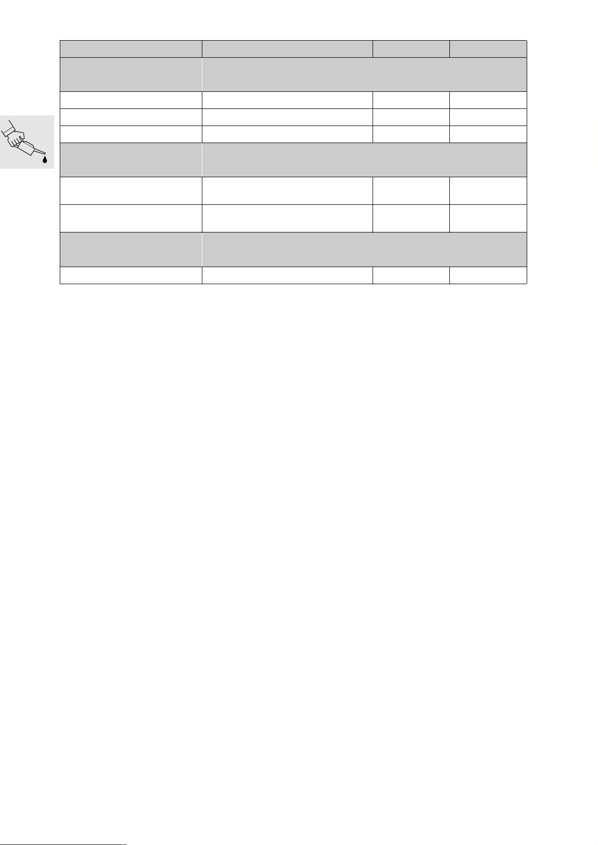
Table of operating fluids
Item Use Order number Quantity
Lubricant
Staburags NBU 30 PTM High-performance lubricating grease 07 55 9 056 992 75 g tube
Optimoly MP 3 High-performance lubricating grease 07 55 9 062 476 100 g tube
Optimoly TA High-temperature assembly grease 18 21 9 062 599 100 g tube
Silicone grease 300, heavy Damping grease 07 58 9 058 193 10 g tube
Retinax EP2 Grease 83 22 9 407 845 100 g tube
Contact spray Contact spray 81 22 9 400 208 300 ml spray
Chain spray Lubricant
Shell HDX2 Lubricant 11 00 7 660 830 400 g tube
Klüberpaste 46 MR 401 High-temperature lubricant 11 00 7 660 831 60 g tube
MOLYKOTE 111 Silicon grease 11 00 7 660 832 100 g tube
Tyre mounting paste Assembly paste
Never Seez compound Lubricating paste 83 23 9 407 830 100 g tube
Grease for lock cylinders Grease 81 22 9 407 421
Rubber care product Rubber care 82 14 9 407 015 60 g tube
Long-life lubricant Lubricant 81 22 9 407 629 250 ml spray
Sealants
3-Bond 1110 B Surface sealant 07 58 9 056 998 5 g tube
3-Bond 1209 Surface sealant 07 58 9 062 376 30 g tube
OMNI VISC 1002 Surface sealant 07 58 1 465 170 90 g tube
Loctite 574 Surface sealant 81 22 9 407 301 50 ml tube
Loctite 577 Thread locking compound 33 11 2 328 736 5 g tube
72 60 2 316 676
72 60 2 316 667
36 32 1 239 263
36 32 1 239 264
50 ml spray
300 ml spray
2.5 kg
100 g
Curil K 2 Heat-conductive sealant 81 22 9 400 243 250 g can
Adhesives and retaining
agents
Loctite 648 Joint adhesive (narrow gap) 07 58 9 067 732 5 g bottle
Loctite 638 Joint adhesive (wide gap) 07 58 9 056 030 10 ml bottle
Loctite 243 Thread retainer, medium-strength 07 58 9 056 031 10 ml bottle
Loctite 270 Thread retainer, strong 81 22 9 400 086 10 ml bottle
Loctite 2701 Thread retainer, strong 33 17 2 331 095 10 ml bottle
Loctite 454 Cyanacrylate adhesive (gel) 07 58 9 062 157 20 g tube
00.13
Page 23
Item Use Order number Quantity
Cleaners
Brake cleaner Cleaners 83 11 9 407 848 600 ml spray
Normal dilution Cleaners 51 91 9 057 940 1 l bottle
Metal Polish Polish for chrome-plated parts 82 14 9 400 890 100 g tube
Testing agents
Penetrant MR 68
Developer MR 70
Installation aid
BMW chilling spray Cooling spray 83 19 9 407 762 300 ml spray
Crack testing agent for aluminium
housings
Crack testing agent for aluminium
housings
83 19 9 407 855 500 ml spray
81 22 9 407 495 500 ml spray
00.14
Page 24

00
00 Pre-delivery check
Contents Page
General view of crated motorcycle ...................................................................................17
Checking the shipping crate for damage ......................................................................18
In case of damage in Germany ...............................................................................................18
In case of damage in importer markets ..............................................................................18
Unpack the motorcycle ...........................................................................................................18
Inspecting motorcycle for damage ...................................................................................19
Checking that delivery is complete ..................................................................................19
Installing remaining items on motorcycle .....................................................................19
Filling and charging the battery .........................................................................................20
Removing the battery ..................................................................................................................20
Filling and charging the battery ...............................................................................................21
Checking engine oil level .......................................................................................................22
Checking tyre pressures .........................................................................................................22
Final inspection and function check ................................................................................23
Final cleaning ................................................................................................................................23
Handover .........................................................................................................................................23
00.15
Page 25

00.16
Page 26
00
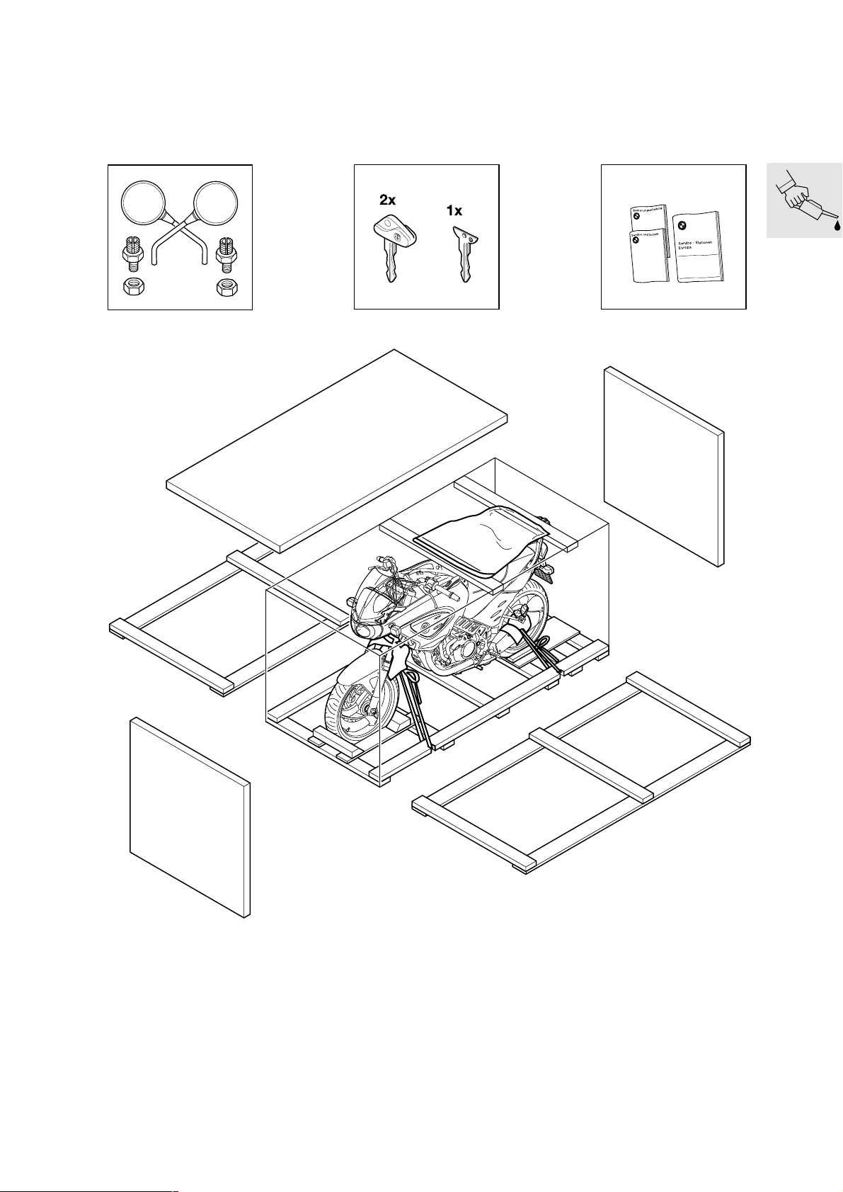
General view of crated motorcycle
K14009440
00.17
Page 27

Checking the shipping crate for damage
When the motorcycle arrives, check the crate im-
•
mediately for damage and if necessary examine
the contents for consequential damage.
00 11
Unpack the motorcycle
Lever off the cover.
•
Take out the separate pack of items.
•
Force off cross-struts with a suitable lever.
•
In case of damage in Germany
Note the damage on the delivery slip.
•
Read the information sheet on damage in transit.
•
Notify the supplier without delay (e.g. freight
•
company or DB) and also
Bavaria Wirtschaftsagentur GmbH
Abteilung ZW - 12
D-80788 München
Tel. +49 89/14327-632
Fax. + 49 89/14327-709
In case of damage in importer markets
Note the damage on the delivery slip.
•
Comply with specific national market proce-
•
dures.
In case of doubt, please submit enquiries to:
Bavaria Wirtschaftsagentur GmbH
Abteilung ZW - 12
D-80788 München
Tel. +49 89/14327-632
Fax. +49 89 14327-709
Notify the supplier (e.g. freight company) without
•
delay.
e Attention:
Do not knock the cross-struts out or the motorcycle
may be damaged.
Remove the end-walls.
•
Remove the side-walls.
•
e Attention:
Make sure that the motorcycle cannot topple.
Remove the straps at front and rear.
•
e Attention:
Remove any nails projecting from the base of the
packing or lying on the base or on the floor.
Push the motorcycle forward off the pallet.
•
Remove the set of keys from the left rear footrest.
•
Dispose of the packing materials in an environ-
•
mentally responsible manner as described in Circular No. 23/91 - Sales.
Check the contents of the enclosed pack of
•
items:
– Mirrors with clamping screws and nuts
– Rider's Manual
– Maintenance Instructions
– Booklet listing service centres in Europe
– BMW emergency service sticker
– Handling instructions for batteries
00.18
Page 28
00 11 Inspecting motorcycle for dam-
age
Check for damage.
•
Use the “express handling service” to notify
•
BMW Motorrad,
UX-VS-1
Fax:+ 49 89-382-33220
Rectify the fault.
•
If parts are needed, order them through the usual
•
channel.
Costs are to be processed by the warranty claim
•
system (stage 4). Defect codes:
– Parts missing 10 01 00 00 00
– Parts damaged 10 02 00 00 00
– Incorrect parts delivered 10 03 00 00 00
00 11
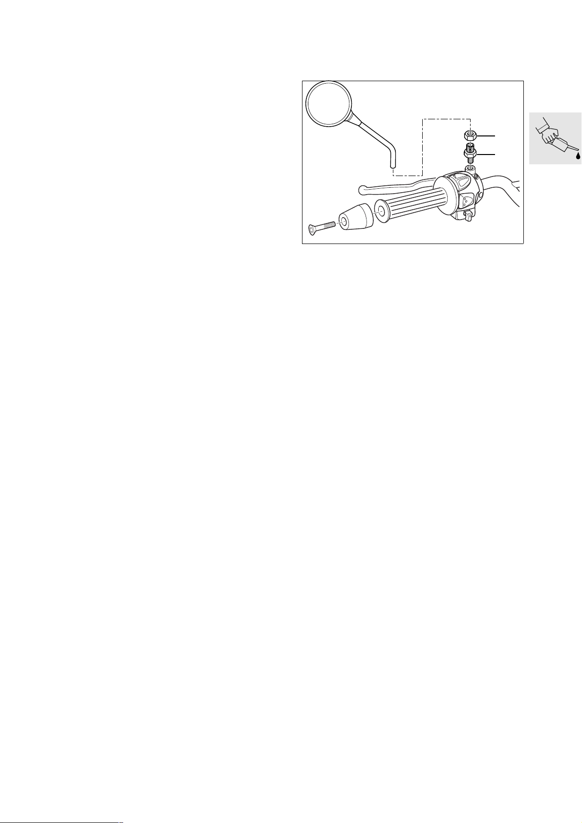
Installing remaining items on
motorcycle
1
2
Checking that delivery is complete
All optional extras
•
Toolkit:
•
– screwdriver, reversible blade
– crosshead screwdriver, small
– 3 open-end wrenches
w/f 8×10, 14, 15
– spark plug wrench
– 3 Allen keys
Torx T15, T25, T30
– 4 fuses
7.5 A, 10 A, 15 A, 20 A
– Breakdown kit
Documentation
•
Vehicle keys, 3 of
•
E000310
Fit clamp screw (2) to handlebar fitting.
•
Install mirror and secure by tightening nut (1).
•
X Tightening torque:
Clamp screw to handlebar fitting.................. 21 Nm
Union nut for mirror ...................................... 18 Nm
00.19
Page 29
1 2
3
5
4
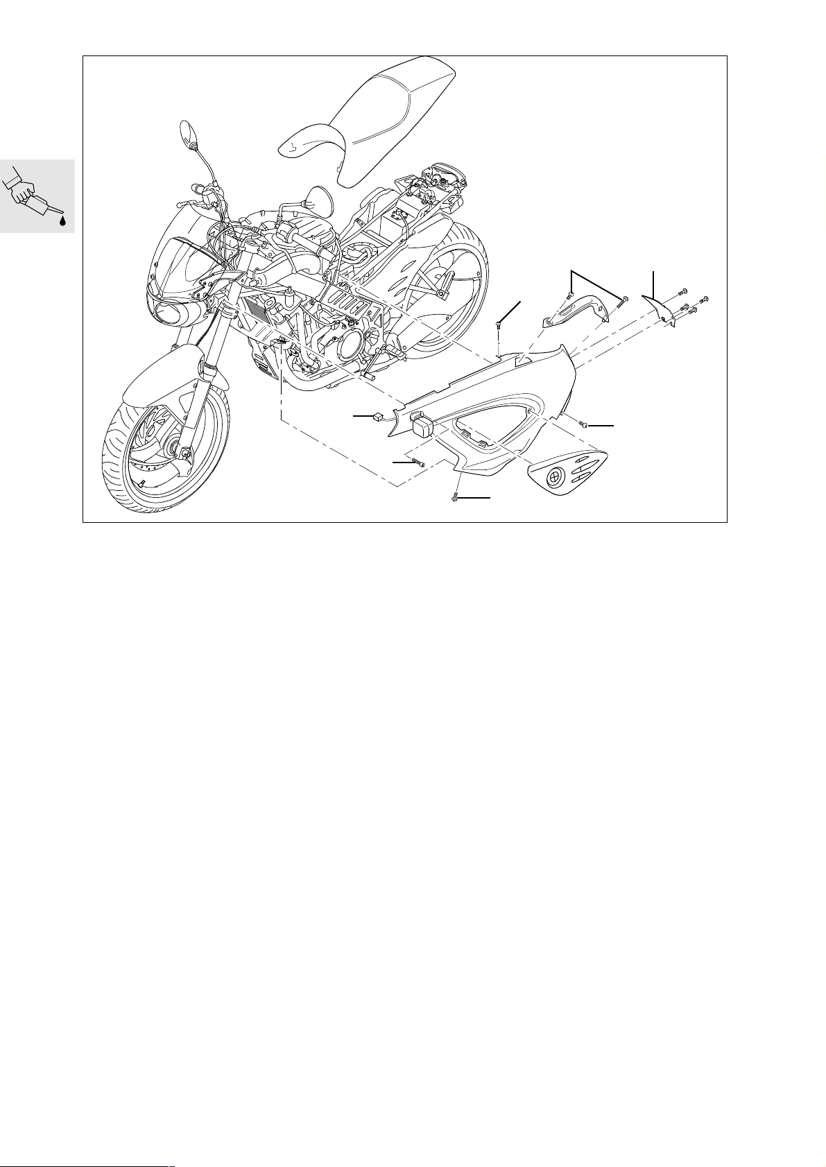
61 21 Filling and charging the battery 61 21 010 Removing the battery
– Place the motorcycle on the auxiliary stand,
BMW No. 00 1 620.
– Remove seat.
Remove securing screws for stowage-compart-
•
ment rail (1) and remove left stowage-compartment rail; use wrench from toolkit if necessary.
Remove fasteners of rear cover and remove rear
•
cover (2).
Disconnect the plug for flashing turn indicator (5).
•
Remove securing screw for flashing turn indica-
•
tor (4).
Remove screws securing left cover (3).
•
Remove the left cover.
•
3
3
K14000450
00.20
Page 30
- UPPER LEVEL-
- LOWER LEVEL-
K14000460
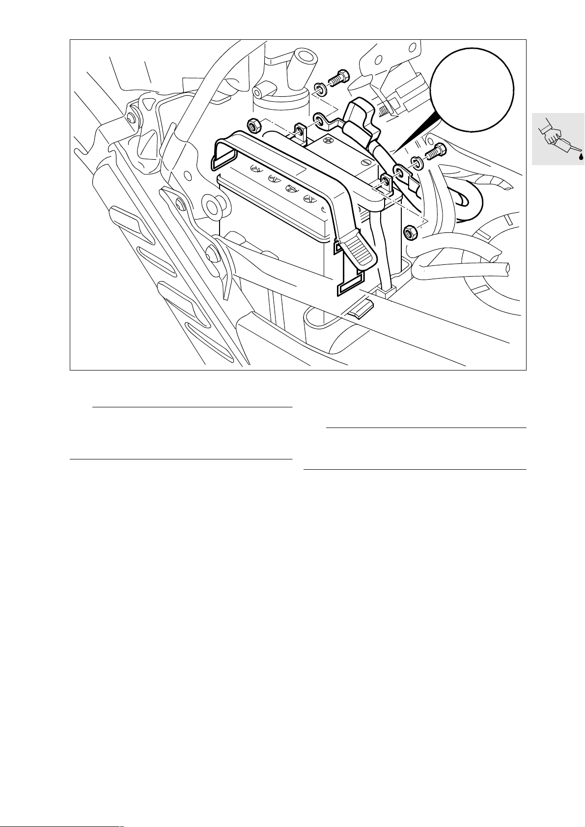
61 21 Filling and charging the battery
d Warning:
Battery acid is highly caustic.
Protect your eyes, face, hands, clothing and the
paintwork.
Disengage the rubber strap holding the battery.
•
Disconnect the battery breather hose.
•
Remove the battery.
•
Fill all the cells with pure battery acid of
•
density 1.28 to the Upper Level mark.
Allow the battery to stand for approximately
•
30 minutes.
The battery does not achieve full charge capacity
•
from being filled, so it has to be charged with a
battery charger.
L Note:
Follow the instructions for use supplied with the battery charger.
Charge current (A)
.........................10 % of rated battery capacity (Ah)
Charging time
..............................................................5-10 hours
Battery charge can be measured by checking
•
the density of the battery acid.
Acid density
Battery fully charged
............1.26-1.30 at a temperature of 20 °C (68 °F)
Shake the battery slightly to allow the gas bub-
•
bles to escape.
Wait until the battery acid has settled, check that
•
no more bubbles rise and if necessary, top up
the acid to the max. mark.
Reinstall the plugs.
•
Make a note of the charging date on the battery.
•
00.21
Page 31

e Attention:
Connect the positive battery terminal first, then the
negative terminal.
Install the battery.
•
L Note:
When connecting the battery lead, always make
sure that the spring washer is between the screw
head and the battery lead.
Checking engine oil level
00 00
Check whether there is oil in the tank (e.g. dip-
•
stick wetted).
e Attention:
Top up the level if there is no engine oil in the tank.
Checking tyre pressures
Apply acid-proof grease to the battery terminal
•
posts.
Connect the battery breather hose.
•
Install the left cover.
•
Install the rear cover.
•
Install the stowage-compartment rail.
•
Install the seat.
•
X Tightening torque:
Positive and negative leads to battery ............ 7 Nm
Cover, rear, to covers left and right and
to stowage-compartment frame .....................2 Nm
Cover, front, to left and right covers ............... 1 Nm
Left and right covers to main frame ................ 2 Nm
Left and right covers to air duct...................... 3 Nm
Turn indicators, left and right, to fairing bracket... 3 Nm
Stowage-compartment railing to stowage-
compartment frame........................................ 9 Nm
Check/correct tyre pressures.
•
Tyre pressures:
one-up ...............................front 2.2 bar (31.91 psi)
........................................... rear 2.5 bar (36.26 psi)
two-up ............................... front 2.2 bar (31.91 psi)
........................................... rear 2.5 bar (36.26 psi)
two-up + luggage............... front 2.2 bar (31.91 psi)
........................................... rear 2.5 bar (36.26 psi)
00.22
BMW recommends Castrol
Page 32

Final inspection and function check
Handover
Clutch
•
Check gear shift action.
•
Steering
•
Handbrake and footbrake
•
Check lights and signalling equipment:
•
– Front and rear parking lights
– Instrument lighting
– Low and high headlight beams, headlight flasher
– Brake light (operate brake at front and rear)
– Turn signals left/right
– Horn
– Telltale and warning lights
– Instruments
Where necessary, check function of optional ex-
•
tras:
ABS: perform starting test. The ABS warning
•
light comes on if there is a fault in the system and
the vehicle is ridden for at least 10 seconds at a
speed in excess of 30 km/h (18.64 miles).
If necessary, take the motorcycle for a test ride.
•
Confirm pre-delivery check in “Maintenance In-
•
structions”
See “Checking motorcycle for damage” if any-
•
thing is unsatisfactory.
00 11 459
Clean the motorcycle.
•
Final cleaning
This is the ideal opportunity to familiarise the customer with the motorcycle in order to ensure the
customer’s satisfaction and safety.
The following points must be demonstrated and
•
explained to the customer:
– Documentation and stowage space
– Toolkit and stowage space
– Suspension preload adjustment to suit total
weight
– How to check the brake fluid
– How to adjust the mirrors
– Controls
– instruments and telltale lights
– Optional equipment and accessories fitted
The user must be given the following information:
•
– Running-in recommendations and inspection in-
tervals
– Safety check
– How to check the oil level in accordance with the
vehicle documentation
L Note:
Do not use a steam or high-pressure water jet. The
high steam or water pressure could damage seals,
the hydraulic system or electrical components.
BMW recommends Castrol
00.23
Page 33

00.24
Page 34

00
00 Maintenance
Contents Page
Key to maintenance intervals ..............................................................................................29
Reading the fault code memory with the MoDiTeC .................................................30
(Inspections I, II, III and IV) .................................................................................................................30
Changing the engine oil [engine only] and oil filter element .............................30
(Inspection I) ......................................................................................................................................30
Preparatory work ...........................................................................................................................30
Draining engine oil ........................................................................................................................30
Replacing oil filter element ........................................................................................................31
Filling with engine oil ....................................................................................................................31
Changing the engine oil [engine and oil tank] and oil filter element .............32
(Inspections II, III and IV) ....................................................................................................................32
Preparatory work ...........................................................................................................................32
Draining engine oil ........................................................................................................................32
Replacing oil filter element ........................................................................................................33
Filling with engine oil ....................................................................................................................33
Cleaning oil strainer in frame ...............................................................................................34
(Inspection II, once only) ....................................................................................................................34
Greasing rubber grommets for cover insert ................................................................34
(Inspections I, II, III and IV) .................................................................................................................34
Checking coolant, topping up if necessary .................................................................35
(Inspections I, II and III) ......................................................................................................................35
Checking coolant ..........................................................................................................................35
Adding coolant ...............................................................................................................................35
Changing coolant .......................................................................................................................36
(Inspection IV, every 2 years) .............................................................................................................36
Checking and adjusting valve clearances ....................................................................38
(Inspections II and III) .........................................................................................................................38
Checking valve clearances .......................................................................................................38
Preparatory work ...............................................................................................................................38
Remove the intake air silencer together with the intake air pipe. ........................................................38
Exposing the radiator ........................................................................................................................38
Exposing cylinder head .....................................................................................................................39
Turning crankshaft to TDC position ....................................................................................................39
Checking valve clearance ..................................................................................................................40
00.25
Page 35

Contents Page
Adjusting valve clearances ........................................................................................................40
Installing cylinder head cover ............................................................................................................41
Replacing spark plug ...............................................................................................................42
(Inspection III) ....................................................................................................................................42
Emptying drain from intake air silencer .........................................................................42
(Inspections I, II and III) ......................................................................................................................42
Replacing air cleaner element ............................................................................................43
(Inspection III) ....................................................................................................................................43
Replacing fuel filter ...................................................................................................................44
(Inspection III, every 40,000 km/24,000 miles) ...................................................................................44
Checking clutch play, adjusting if necessary ..............................................................45
(Inspections I, II and III) ......................................................................................................................45
Checking brake pads and discs for wear, replacing if necessary ...................45
(Inspections II and III) .........................................................................................................................45
Checking brake pads for wear ................................................................................................45
Brake pads, front brake .....................................................................................................................45
Brake pads, rear brake ......................................................................................................................45
Replacing brake pads .................................................................................................................46
Brake pads, front brake .....................................................................................................................46
Brake pads, rear brake ......................................................................................................................47
Checking the brake discs ..........................................................................................................47
Checking brake fluid level at front and rear ................................................................48
(Inspections II and III) .........................................................................................................................48
Brake fluid level (front brake) ....................................................................................................48
Checking brake fluid level (front brake) ..............................................................................................48
Brake fluid level (rear brake) .....................................................................................................48
Checking brake fluid level (rear brake) ...............................................................................................48
Checking operation of brake system and checking for leaks; repairing/
replacing as necessary ...........................................................................................................49
(Inspection III) ....................................................................................................................................49
Changing brake fluid and bleeding brake system ....................................................49
(Inspection IV) ....................................................................................................................................49
Changing brake fluid and bleeding brake system (front brakes) ..............................49
Changing brake fluid and bleeding brake system (rear brakes) ...............................50
Replacing primary sealing boot, front brake master cylinder ...........................52
(Inspection III, every 40,000 km/24,000 miles for motorcycles with ABS) ..........................................52
Replacing primary sealing boot, rear brake master cylinder .............................53
(Inspection III, every 40,000 km/24,000 miles for motorcycles with ABS) ..........................................53
Checking toothed belt pulley and sprocket, replacing if necessary .............54
(Inspection III) ....................................................................................................................................54
00.26
Page 36

Contents Page
Replacing toothed belt ............................................................................................................54
(Inspection III) ....................................................................................................................................54
Checking belt tension, adjusting if necessary ...........................................................56
(Inspections I, II and III) ......................................................................................................................56
Checking belt tension .................................................................................................................56
Adjusting belt tension ..................................................................................................................57
Used belt, new belt ...........................................................................................................................57
Checking battery acid level, adding distilled water if necessary ....................59
(Inspections II, III and IV) ....................................................................................................................59
Checking battery acid level ......................................................................................................59
Adding distilled water ..................................................................................................................59
Cleaning and greasing battery terminals, if necessary .........................................59
(Inspection IV) ....................................................................................................................................59
Checking and adjusting steering head bearing play,
replacing if necessary ..............................................................................................................60
(Inspections II and III) .........................................................................................................................60
Checking steering head bearing play ..................................................................................60
Adjusting steering head bearing play ...................................................................................60
Greasing side stand ..................................................................................................................61
(Inspections II and III) .........................................................................................................................61
Side stand ........................................................................................................................................61
Checking specified torque of threaded fasteners with torque wrench .......61
(Inspections I, II, III and IV) .................................................................................................................61
Final inspection with road safety and functional check .......................................62
(Inspections I, II, III and IV) .................................................................................................................62
Road safety check .............................................................................................................................62
Tyre tread depth (recommended minimum value) ...............................................................................62
Tyre pressures (tyres cold) .................................................................................................................62
Roadworthiness check ......................................................................................................................62
00.27
Page 37

00.28
Page 38

00
Key to maintenance intervals
Maintenance tasks consist of the first Inspection (after the first 1,000 km/600 miles), the BMW Service,
BMW Inspection and BMW Annual Service.
Inspection 1,000 km (600 miles)
BMW Running-in Check after the
first 1,000 km (600 miles).
BMW Service
After the first 10,000 km (6,000 miles) and each additional 20,000 km (12,000 miles)
(at 30,000 km ... 50,000 km ... 70,000 km)
(at 18,000 miles ... 30,000 miles ... 42,000 miles).
BMW Inspection
After the first 20,000 km (12,000 miles) and each
additional 20,000 km (12,000 miles)
(at 40,000 km ... 60,000 km ... 80,000 km)
(at 24,000 miles ... 36,000 miles ... 48,000 miles).
BMW Annual Service
Certain maintenance tasks depend on elapsed time
as well as the distance the motorcycle has covered.
They should therefore be carried out at least once a
year (e. g. changing brake fluid).
If these tasks cannot be carried out during a Service
or an Inspection, a BMW Annual Service must be
performed.
In this Repair Manual, the individual maintenance intervals are shown by the following codes:
— Inspection at 1,000 km (600 miles)......................I
— BMW Service at 10,000 km (6,000 miles)...........II
— BMW Inspection at 20,000 km (12,000 miles) .. III
— BMW Annual Service........................................ IV
00.29
Page 39

00 13 624 Reading the fault code mem-
ory with the MoDiTeC
00 11 209
Changing the engine oil
[engine only] and oil filter element
(Inspections I, II, III and IV)
K14000010
– Place the motorcycle on the auxiliary stand,
BMW No. 00 1 620.
Unclip diagnosis plug (arrow) behind cover on
•
right.
Connect the diagnosis unit to the diagnosis plug.
•
Read out the fault memory.
•
Perform any repair work indicated.
•
(Inspection I)
L Note:
If an engine failure occurs, the oil tank and feed line
must be flushed with thin oil, and then blown
through with compressed air (a 11.17).
00 11 209
– Remove cover for belt sprocket from engine.
– Place the motorcycle on the auxiliary stand,
BMW No. 00 1 620.
00 11 209
Preparatory work
Draining engine oil
d Warning:
Observe the hazard avoidance instructions for running internal combustion engines in enclosed spaces.
Warm up the engine to operating temperature.
•
Place a suitable container in position to catch the
•
oil.
Remove the oil drain plug from the engine and
•
fully drain the oil from the engine.
00.30
Page 40

00 11 215 Replacing oil filter element
1
3
00 11 215
Install the oil drain plug in the engine with a new
•
sealing ring and tighten.
Fill the oil tank with 0.5 l
•
(0.88 Imp. pints/0.53 US quarts) of engine oil and
install the filler cap.
2
L Note:
The requisite quantity of oil is 0.5 (0.88 Imp. pints/
0.53 US quarts) to 1,5 l (2.64 Imp. pints/1.59 US
quarts), depending on operating status.
Filling with engine oil
11 7 511
K14000160
Remove the left-hand screw (3) securing the oil-
•
filter cover (1).
Remove the cable for the neutral-indicator
•
switch from its guide.
Engage the oil drain guide, BMWNo.117511,
•
on the pins (arrows) on the engine block.
Position a drip tray beneath the engine.
•
Remove the screws (2) and remove the oil-filter
•
cover.
Remove the filter element.
•
Fully drain the oil and clean the oil-filter housing.
•
e Attention:
Dispose of the used oil and oil filter in an environmentally compatible manner.
Fit a new filter element onto the oil-filter cover.
•
Coat the O-ring of the filter element lightly with
•
oil.
Check the O-ring of the oil-filter cover for dam-
•
age and replace if necessary.
Install the oil-filter cover complete with filter ele-
•
ment.
Installation is the reverse of the removal proce-
•
dure: pay particular attention to the following.
d Warning:
Observe the hazard avoidance instructions for running internal combustion engines in enclosed spaces.
Installation is the reverse of the removal proce-
•
dure: pay particular attention to the following.
d Warning:
Observe the hazard avoidance instructions for running internal combustion engines in enclosed spaces.
Check the oil level with the engine at operating
•
temperature, proceeding as follows:
L Note:
Lower the dipstick into the oil filler neck, but do not
engage the threads.
1. Make sure the engine is at operating temperature, and allow it to idle for 1 minute.
2. Switch off the engine and check the oil level with
the dipstick.
L Note:
Do not reinstall the belt sprocket cover at this stage,
if other maintenance work has to be performed on
assemblies normally concealed by this component.
X Tightening torque:
Oil filter cover............................................... 10 Nm
Sprocket cover to engine ............................... 2 Nm
K14000170
3. Top up the engine oil if necessary, but no higher
than the midway mark (arrow) and repeat
steps 1) to 3).
BMW recommends Castrol
00.31
Page 41

e Attention:
Do not use synthetic oils.
Operating fluids:
Brand-name HD oil, API classification SF, SG or SH;
suffix letters CD or CE are permitted; alternatively,
brand-name HD oil of CCMC classification G4 or
G5; suffix PD2 is permitted.
Capacity, engine:
with filter replacement ......................................0.5 l
.............................(0.88 Imp. pints/0.53 US quarts)
X Tightening torque:
Oil drain plug, engine ................................... 40 Nm
00 11 215
Changing the engine oil [engine and oil tank] and oil filter element
(Inspections II, III and IV)
L Note:
If an engine failure occurs, the oil tank and feed line
must be flushed with thin oil, and then blown
through with compressed air (a 11.17).
00 11 215
– Place motorcycle on side stand.
– Remove cover for belt sprocket from engine.
00 11 215
Preparatory work
Draining engine oil
d Warning:
Observe the hazard avoidance instructions for running internal combustion engines in enclosed spaces.
Warm up the engine to operating temperature.
•
Place a suitable container in position to catch the
•
oil.
1
K14000150
Remove the filler cap from the oil tank.
•
Remove the oil drain plug from the frame (1).
•
Fully drain the oil.
•
– Place the motorcycle on the auxiliary stand,
BMW No. 00 1 620.
Remove the oil drain plug from the engine and
•
fully drain the oil from the engine.
00.32
Page 42

00 11 215 Replacing oil filter element
1
00 11 215
Install the oil drain plug in the frame with a new
•
sealing ring and tighten.
Install the oil drain plug in the engine with a new
•
sealing ring and tighten.
Fill the oil tank with 2 l (3.52 Imp. pints/2.11 US quarts)
•
of engine oil and install the filler cap.
Filling with engine oil
2
3
11 7 511
K14000160
Remove the left-hand screw (3) securing the oil-
•
filter cover (1).
Remove the cable for the neutral-indicator
•
switch from its guide.
Engage the oil drain guide, BMWNo.117511,
•
on the pins (arrows) on the engine block.
Position a drip tray beneath the engine.
•
Remove the screws (2) and remove the oil-filter
•
cover.
Remove the filter element.
•
Fully drain the oil and clean the oil-filter housing.
•
e Attention:
Dispose of the used oil and oil filter in an environmentally compatible manner.
d Warning:
Observe the hazard avoidance instructions for running internal combustion engines in enclosed spaces.
Run the engine for thirty seconds.
•
Add another 0.5 l (0.88 Imp. pints/0.53 US quarts)
•
of engine oil to the oil tank.
Installation is the reverse of the removal proce-
•
dure: pay particular attention to the following.
Check the oil level with the engine at operating
•
temperature, proceeding as follows:
L Note:
Lower the dipstick into the oil filler neck, but do not
engage the threads.
1. Make sure the engine is at operating temperature, and allow it to idle for 1 minute.
2. Switch off the engine and check the oil level with
the dipstick.
Fit a new filter element onto the oil-filter cover.
•
Coat the O-ring of the filter element lightly with
•
oil.
Check the O-ring of the oil-filter cover for dam-
•
age and replace if necessary.
Install the oil-filter cover complete with filter ele-
•
ment.
Installation is the reverse of the removal proce-
•
dure: pay particular attention to the following.
L Note:
Do not reinstall the belt sprocket cover at this stage,
if other maintenance work has to be performed on
assemblies normally concealed by this component.
X Tightening torque:
Oil filter cover............................................... 10 Nm
Sprocket cover to engine ............................... 2 Nm
K14000170
3. Top up the engine oil if necessary, but no higher
than the midway mark (arrow) and repeat steps
1) to 3).
BMW recommends Castrol
00.33
Page 43

e Attention:
Do not use synthetic oils.
Operating fluids:
Brand-name HD oil, API classification SF, SG or SH;
suffix letters CD or CE are permitted; alternatively,
brand-name HD oil of CCMC classification G4 or G5;
suffix PD2 is permitted.
Capacities, engine and oil tank:
with filter replacement ......................................2.5 l
.............................(4.40 Imp. pints/2.64 US quarts)
X Tightening torque:
Oil drain plug, engine ................................... 40 Nm
Drain plug, frame oil tank.............................. 21 Nm
Cleaning oil strainer in frame
(Inspection II, once only)
– Drain engine oil (
– Remove left cover (
a 00.32).
a 46.6).
X Tightening torque:
Oil drain plug, engine ................................... 40 Nm
Oil drain plug, frame oil tank......................... 21 Nm
Oil line to frame............................................ 42 Nm
Oil strainer to frame...................................... 80 Nm
Oil tank cover to frame................................... 5 Nm
Right and left covers to main frame................ 2 Nm
Right and left covers to air duct ..................... 3 Nm
Right and left covers to cover, front ............... 1 Nm
Right and left turn indicators to fairing
bracket........................................................... 3 Nm
Cover, rear, to right and left covers and
stowage-compartment frame ......................... 2 Nm
Stowage-compartment rail to stowage-compart-
ment frame..................................................... 9 Nm
Release lever to release shaft....................... 10 Nm
Greasing rubber grommets for cover insert
(Inspections I, II, III and IV)
– Remove cover inserts.
1
2
4
3
K14000350
Remove oil-tank cover (1).
•
Disengage clutch cable (arrow).
•
Remove release lever (3).
•
Disconnect oil line (4).
•
Remove oil strainer (2) and clean it with com-
•
pressed air.
Installation is the reverse of the removal proce-
•
dure: pay particular attention to the following.
Always install new seals for the oil line and oil
•
strainer.
Adjust clutch play (a 00.45).
•
6
5
K14000380
Coat pin (5) and hook (6) with rubber care prod-
•
uct.
Install cover insert.
•
00.34
Page 44

Checking coolant, topping up if necessary
(Inspections I, II and III)
e Attention:
Check coolant level only when the engine is cold.
Do not refill the coolant expansion tank if valve clearance still has to be checked/adjusted.
Check antifreeze concentration in the expansion
•
tank, top up antifreeze if necessary.
L Note:
Mix the coolant to a ratio of 50 % antifreeze,
50 % water.
Check coolant level in expansion tank.
•
If the coolant level is below the MIN mark, top up
•
coolant to the MIN mark.
Checking coolant
– Place the motorcycle on the auxiliary stand,
BMWNo.001620.
Check coolant level through the slot in the insert
•
in the left cover.
Top up the coolant if the level is below the MIN
•
mark.
Adding coolant
– Remove cover insert from left cover.
A
B
Maximum level ..................................................... A
Minimum level...................................................... B
Installation is the reverse of the removal proce-
•
dure.
K14000100
e Attention:
Anti-freeze protection must be guaranteed to at
least -30 °C (-22 °F). Use only nitrite-free long-term
antifreeze and corrosion inhibitor.
When the engine is cold, do not top up expansion
tank past the MIN mark (B).
00.35
Page 45

17 00 035 Changing coolant
(Inspection IV, every 2 years)
– Remove left cover (a 46.6).
– Place motorcycle on side stand.
Position a drip tray beneath the engine.
•
2
1
K14000110
Remove drain plug (1) from water pump.
•
Hold a funnel below the drain and open the radi-
•
ator cap.
Drain off all the coolant.
•
K14000130
Remove fastener (2), lift out the expansion tank
•
and drain off all coolant.
e Attention:
Dispose of old coolant in an environmentally compatible manner.
L Note:
Do not install and refill the coolant expansion tank if
valve clearance still has to be checked.
Install the expansion tank.
•
Install the drain plug with a new sealing ring and
•
tighten.
Tighten hose clamp securing coolant hose.
•
– Place the motorcycle on the auxiliary stand,
BMW No. 00 1 620.
K14000120
Disconnect the coolant hose (arrow) at the frame
•
on the left and drain the radiator.
00.36
Page 46

1
K14000140
Slacken bleed screw (1) in cylinder head.
•
Connect a hose to the bleed screw.
•
Fill the radiator until coolant escapes at the bleed
•
screw; repeatedly squeeze the coolant hoses to
expel the air.
Tighten bleed screw (1).
•
K14000130
Filling capacity
Cooling system ................................................1.3 l
.............................(2.29 Imp. pints/1.37 US quarts)
In expansion tank.............................................0.1 l
.............................(0.18 Imp. pints/0.11 US quarts)
Antifreeze
Use only nitrite-free long-term antifreeze and corrosion inhibitor.
Concentration
Antifreeze.........................................................50%
Water ...............................................................50%
Run the engine for a short time, then switch it off.
•
Check coolant level and top up if necessary.
•
Installation is the reverse of the removal proce-
•
dure: pay particular attention to the following.
L Note:
Do not reinstall the cover at this stage, if other maintenance work has to be performed.
X Tightening torque:
Stowage-compartment rail to stowage-compart-
ment frame..................................................... 9 Nm
Cover, rear, to left and right covers and
stowage-compartment frame ......................... 2 Nm
Right and left covers to air duct ..................... 3 Nm
Right and left covers to main frame................ 2 Nm
Right and left covers to cover, front ............... 1 Nm
Right and left turn indicators to fairing bracket3 Nm
Drain plug, water pump................................ 10 Nm
Expansion tank to radiator ............................. 9 Nm
Bleed screw................................................. 12 Nm
Coolant hose to frame.................................... 3 Nm
Top up coolant until the level reaches the top of
•
the filler neck (arrow).
Top up expansion tank to the MIN mark.
•
00.37
Page 47

00 11 602 Checking and adjusting
valve clearances
(Inspections II and III)
0011601
Preparatory work
– Place the motorcycle on the auxiliary stand,
– Remove the left, right and front covers (
Remove the intake air silencer together with the intake air pipe.
•
•
Checking valve clearances
BMW No. 00 1 620.
a 46.6).
Push up the tab to pull the fuse box from the
holder.
Remove the fuel filter from the stowage-compartment frame.
1
K14000030
Disengage the clamp (arrow) securing the
•
breather hose and disconnect the hose from the
intake air silencer.
Carefully disconnect the intake air silencer from
•
the throttle flap stub.
Disengage the intake air pipe with rubber grom-
•
met from the link.
Pull the intake air silencer with intake air pipe to
•
the rear to remove, disconnecting the plug for
the intake-air temperature sensor.
Cover/seal the throttle flap stub.
•
Exposing the radiator
K14000020
Remove fasteners securing stowage-compart-
•
ment frame to main frame (arrows).
Remove stowage-compartment frame (1).
•
K14000040
L Note:
When temporarily securing the expansion tank,
make sure that the cap is above the level of the coolant.
Disconnect the expansion tank from the radiator,
•
pull it to one side and temporarily secure it to the
handlebar with a cable tie or similar.
Protect the interior of the radiator with cardboard
•
or similar.
00.38
Page 48

Exposing cylinder head
1
4
2
3
6
Remove fasteners securing bracket (1) of ignition
•
coil, pull bracket complete with ignition coil (2)
forward and lay it down.
Remove rubber cap (arrow).
•
Release knurled nut (3).
•
Disengage throttle cable from adapter.
•
Use pliers, BMW No. 17 5 500, to release hose
•
clip (5) and disconnect cylinder-head breather
hose (6).
Remove spark plug.
•
5
K14000050
L Note:
Note the position of the two anchorages for ignition
coil (1) on the cylinder-head cover.
Remove 8 fasteners (4) and remove the cylinder-
•
head cover with gasket.
Turning crankshaft to TDC position
Remove the central threaded plug in the magnet
•
housing.
E110410
L Note:
TDC position: Marks on the timing-chain
sprockets (arrows) must be parallel with the cylinder
head, the bores in the timing-chain sprockets are at
the top.
Use an Allen key to turn the crankshaft clockwise
•
to the TDC position.
00.39
Page 49

Checking valve clearance
1
11 1 810
E000160
Use feeler gauges, BMWNo.111810, to meas-
•
ure valve clearances.
Make a note of the valve clearances, or adjust
•
them if necessary.
Valve clearances:
Inlet valve ........ 0.03...0.11 mm (0.0012...0.0043 in)
Exhaust valve .. 0.25...0.33 mm (0.0098...0.0130 in)
00 11 602 Adjusting valve clearances
11 6 570
K14000070
Remove the fasteners securing the chain
•
guide (arrows) and remove chain guide (1).
E000370
Use cable ties (arrow) to secure the timing chain
•
to both sprockets.
Remove the upper section of the camshaft carri-
•
er.
K14000060
L Note:
Watch out for escaping oil and catch it in a suitable
container.
Remove the screw at the oil feed stub pipe and
•
insert locating screw, BMW No. 11 6 570, to
lock the crankshaft at TDC.
e Attention:
Oil the camshafts to facilitate their removal and installation.
Carefully remove the inlet camshaft and lay it
•
aside.
Carefully remove the exhaust camshaft and lay it
•
aside.
00.40
Page 50

E000380
Turn the bucket tappet until the shim (arrow) can
•
be levered out at the groove in the bucket tappet.
Before installing new shims, check thickness
•
with a micrometer.
Position the shim in the bucket tappet.
•
e Attention:
Check that the shim is correctly seated in the bucket
tappet.
Installation is the reverse of the removal proce-
•
dure: pay particular attention to the following.
When installing the inlet camshaft, press the
•
chain rail back against the chain tensioner if necessary.
L Note:
TDC position: Marks on the timing-chain sprockets
must be parallel with the cylinder head, the bores in
the timing-chain sprockets are at the top.
Before installing the chain guide, remove the lo-
•
cating screw and install the screw plug, fitted
with a new sealing ring.
Turn the engine over once and bring it to TDC.
•
Check the TDC positions of the camshaft
•
sprockets.
Check valve clearances.
•
Clean the threads of the securing screws for the
•
chain guide, coat threads with Loctite 243 and
install the screws.
Installing cylinder head cover
Before installing the cylinder head cover, remove
•
all traces of the gasket and clean the sealing face
with degreasing agent. Also clean the groove
and the seating faces for the gasket.
L Note:
Do not reinstall the unit consisting of intake air silencer, intake duct and battery carrier at this stage,
if the fuel filter has to be removed.
Make sure that the intake pipe is correctly seated on
the throttle valve stub.
If necessary, top up the coolant in the expansion
•
tank.
Valve clearances:
Inlet valve ........ 0.03...0.11 mm (0.0012...0.0043 in)
Exhaust valve .. 0.25...0.33 mm (0.0098...0.0130 in)
X Tightening torque:
Stowage-compartment rail to
stowage-compartment frame ......................... 9 Nm
Cover, rear, to left and right covers and
stowage-compartment frame ......................... 2 Nm
Right and left covers to air duct ..................... 3 Nm
Right and left covers to main frame................ 2 Nm
Right and left covers to cover, front ............... 1 Nm
Right and left turn indicators to fairing bracket3 Nm
Cover, front, to main frame............................. 2 Nm
Fuel filter to stowage-compartment frame ...... 9 Nm
Stowage-compartment frame to main frame .. 9 Nm
Cylinder head cover to cylinder head ........... 10 Nm
Bracket for ignition coil to cylinder head......... 9 Nm
Spark plug in cylinder head.......................... 20 Nm
Expansion tank to radiator ............................. 9 Nm
Camshaft bearing cap to cylinder head ........ 10 Nm
Chain guide to bearing cap
(clean thread + Loctite 243).......................... 10 Nm
Socket-head screw (bore for
locating screw)............................................. 25 Nm
00.41
Page 51

00 12 620 Replacing spark plug
(Inspection III)
– Place the motorcycle on the auxiliary stand,
BMW No. 00 1 620.
– Remove right cover (
a 46.6).
1
2
K14000180
Emptying drain from intake air silencer
(Inspections I, II and III)
– Place the motorcycle on the auxiliary stand,
BMW No. 00 1 620.
– Remove right cover (
Have a funnel and drip tray ready.
•
a 46.6).
Twist rubber ring (1) to release ignition coil from
•
bracket (2).
Disconnect the ignition coil from the spark plug.
•
Remove the spark plug with the w/f 18 socket
•
wrench.
Installation is the reverse of the removal proce-
•
dure.
X Tightening torque:
Spark plug.................................................... 20 Nm
Right and left covers to main frame................ 2 Nm
Right and left covers to air duct...................... 3 Nm
Right and left covers to cover, front................ 1 Nm
Right and left turn indicators to fairing bracket 3 Nm
Cover, rear, to right and left covers and
stowage-compartment frame ......................... 2 Nm
Stowage-compartment rail to stowage-compart-
ment frame.....................................................9 Nm
K14000190
Open the hose clamp and remove the
•
cap (arrow).
e Attention:
Dispose of used oil in an environmentally compatible manner.
X Tightening torque:
Stowage-compartment rail to stowage-compart-
ment frame..................................................... 9 Nm
Cover, rear, to left and right covers and
stowage-compartment frame ......................... 2 Nm
Right and left covers to air duct ..................... 3 Nm
Right and left covers to main frame................ 2 Nm
Cover, front, to right and left covers............... 1 Nm
Right and left turn indicators to fairing bracket3 Nm
00.42
Page 52

00 13 630 Replacing air cleaner ele-
ment
(Inspection III)
– Place the motorcycle on the auxiliary stand,
BMWNo.001620.
– Remove left cover (
a 46.6).
1
2
K14000080
Remove the fasteners securing the intake pipe to
•
intake air silencer (1).
Swing intake pipe (2) to the side and lift it up and
•
out of the hook.
3
K1400090
L Note:
Compressing the front part of the air filter element
facilitates removal.
Remove air filter element (3).
•
Clean the intake air silencer.
•
Installation is the reverse of the removal proce-
•
dure: pay particular attention to the following.
L Note:
Compressing the front part of the air filter element
facilitates installation.
Disengage the intake air pipe with rubber
•
grommet (arrow) from the link at the front.
K14000470
Engage the intake pipe in the hook of the intake
•
air silencer at the bottom and tilt it up.
X Tightening torque:
Stowage-compartment rail to stowage-compart-
ment frame..................................................... 9 Nm
Cover, rear, to right and left covers and
stowage-compartment frame ......................... 2 Nm
Right and left covers to air duct ..................... 2 Nm
Right and left covers to main frame................ 2 Nm
Cover, front, to right and left covers............... 1 Nm
Right and left turn indicators to fairing bracket3 Nm
Intake air pipe to
intake air silencer ........................................... 9 Nm
00.43
Page 53

0016617 Replacing fuel filter
(Inspection III, every 40,000 km/24,000 miles)
d Warning:
Comply with safety precautions when handling or
working with fuel; note that the fuel lines are pressurised.
– Place the motorcycle on the auxiliary stand,
BMW No. 00 1 620.
– Remove left cover (a 46.6).
1
5
4
2
Installation is the reverse of the removal proce-
•
dure: pay particular attention to the following.
e Attention:
Note the installed positions of fuel feed line (3) and
fuel return line (2).
Close hose clamps with pliers,
•
BMW No. 13 1 500.
X Tightening torque:
Stowage-compartment rail to stowage-compart-
ment frame..................................................... 9 Nm
Cover, rear, to right and left covers and
stowage-compartment frame ......................... 2 Nm
Right and left covers to air duct ..................... 3 Nm
Right and left covers to main frame................ 2 Nm
Cover, front, to right and left covers............... 1 Nm
Right and left turn indicators to fairing bracket3 Nm
Fuel filter to stowage-compartment frame ...... 9 Nm
3
Remove the fastener securing the fuel filter to the
•
stowage-compartment frame (4).
Close off fuel supply line (3) and the line to the
•
fuel injector (5) with hose clips,
BMW No. 13 3 010.
Slacken the hose clamps.
•
13 3 010
K14000360
d Warning:
Fuel escapes from the filter when the lines are disconnected.
Disconnect fuel lines (2, 3, 5) from the filter.
•
Remove clamp (1) from the fuel filter.
•
00.44
Page 54

21 00 004 Checking clutch play, adjust-
ing if necessary
Checking brake pads and discs for wear, replacing if necessary
(Inspections I, II and III)
A
1
E000240
Release lever (1) on the gearbox must be located
•
on the splines such that when it is pressed forward as far as the release point, distance “A” is
as specified.
Distance “A” ......... 47...52 mm (1.8504...2.0473 in)
(Inspections II and III)
Checking brake pads for wear
Brake pads, front brake
K14000210
Visually inspect the brake pads.
•
– Replace the brake pads if wear marks (arrows)
are no longer clearly visible.
2
3
B
K14000200
Adjust distance “B” by turning adjusting
•
screw (2) on the clutch handlebar lever.
Lock adjusting screw (2) with knurled nut (3).
•
Distance “B”........ 1.0...2.0 mm (0.0394...0.0787 in)
X Tightening torque:
Release lever to release shaft....................... 10 Nm
Brake pads, rear brake
K14000220
Visually inspect the brake pads.
•
– Replace the brake pads if wear marks (arrows)
are no longer clearly visible.
00.45
Page 55

2
MIN
C1340370
Minimum lining thickness
The brake pads have a clearly visible
chamfer (arrow) as wear indicator.
Replacing brake pads
e Attention:
Do not operate the brake when dismantled.
Do not permit the brake pads to wear past the specified minimum thickness.
Always replace the brake pads as a complete set.
00 34 630 Brake pads, front brake
– Place the motorcycle on the auxiliary stand,
BMW No. 00 1 620.
Press the brake caliper against the brake disc in
•
order to force the piston back.
3
1
K14000230
Remove keeper (1).
•
Drive out retaining pin (3).
•
Remove the brake pads.
•
Remove fasteners (2) and remove brake caliper.
•
4
E340010
Make sure that spring (4) is correctly seated and
•
installed right way round: engraved arrow must
point in forward direction of travel.
Install the brake pads.
•
Install the keeper and the retaining pin.
•
Install brake caliper.
•
Operate brake several times until brake pads are
•
bedded.
X Tightening torque:
Brake caliper to slider tube .......................... 41 Nm
00.46
Page 56

00 34 633 Brake pads, rear brake
Press the brake caliper against the brake disc in
•
order to force the piston back.
1
34 1 571
2
K14000560
Remove keeper (1).
•
Remove retaining pin (2) with press-out tool,
•
BMWNo.341571.
Remove brake pads.
•
Installation is the reverse of the removal proce-
•
dure: pay particular attention to the following.
Checking the brake discs
Carefully check the brake discs for cracking,
•
damage, deformation and scoring.
K14000250
Measure the thickness of the brake discs at sev-
•
eral points with a caliper gauge.
Brake disc wear limit
Front brake disc....................... 4.5 mm (0.1772 in)
Rear brake disc........................ 4.5 mm (0.1772 in)
L Note:
Remove the silencer prior to installation of the retaining pin (a 18.5).
Operate brake several times until brake pads are
•
bedded.
00.47
Page 57

Checking brake fluid level at front and rear
Brake fluid level (rear brake)
(Inspections II and III)
L Note:
The volume of the brake fluid (MIN/MAX) is sufficient
for brake-pad thicknesses from new to the wear
limit.
It is not normally necessary to top up the fluid to accommodate lining wear.
A level below MIN indicates the possibility of other
faults.
Brake fluid level (front brake)
Checking brake fluid level (front brake)
MAX
Checking brake fluid level (rear brake)
– Place the motorcycle on the auxiliary stand,
BMW No. 00 1 620.
MAX
MIN
K14000260
Maximum level ............................................ “MAX”
Minimum level .............................................. “MIN”
Brake fluid ...................................................DOT 4
MIN
E000120
– Support the motorcycle on its side stand.
Move the handlebars to the straight-ahead posi-
•
tion.
– The brake fluid must be between the top edge
and the bottom edge of the sight glass.
Brake fluid....................................................DOT 4
00.48
Page 58

Checking operation of brake system and checking for leaks; repairing/ replacing as necessary
(Inspection III)
Check all brake lines for damage and correct
•
routing.
Wipe down all threaded unions on the brake lines
•
and check them.
Apply firm pressure to the brake lever and brake
•
pedal and keep this pressure applied for a few
moments.
Release the brakes and check the brake lines for
•
leaks.
d Warning:
Defective lines and threaded unions in the brake
system must always be replaced without delay.
00 34 606
Changing brake fluid and
bleeding brake system
(Inspection IV)
e Attention:
Refer to notes on the hazards involved in handling
brake fluid.
Do not allow brake fluid to come into contact with
painted parts of the motorcycle, because brake fluid
destroys paint.
L Note:
This description applies for the brake filling and
bleeding unit with extraction of the brake fluid by a
partial vacuum at the brake caliper.
If other devices are used, comply with their manufacturers’ instructions.
Changing brake fluid and bleeding brake system (front brakes)
– Remove the brake pads (a 00.46).
1
34 1 500
E000420
Using special tool, BMW No. 34 1 500, and
•
strips of metal sheet (1)
(approx. 7 mm/0.2756 in thick), force back the
brake pads.
00.49
Page 59

1
E000120
– Support the motorcycle on its side stand.
Move the handlebars to the straight-ahead posi-
•
tion.
Remove cap (1) with rubber diaphragm, draw off
•
the old brake fluid and clean the reservoir.
Top up the brake fluid in the reservoir to the
•
specified level.
Connect the brake bleeding device to the bleed
•
screw on the brake caliper.
Open the bleed screw by half a turn.
•
L Note:
[ABS] Place rubber diaphragm and reservoir cap in
position.
Carefully tighten the securing screws.
e Attention:
If the vehicle is equipped with ABS, the brake system has to be bled using the BMWMoDiTeC, and
the Control Units, Toolbox ABS, routine; this procedure is supplementary to that described in the Repair Manual.
If the BMWMoDiTeC is not used there is a danger of
residual air remaining in the control circuits of the
ABS system.
[ABS] Bleed the brakes using the
•
BMWMoDiTeC.
Brake fluid ...................................................DOT 4
X Tightening torque:
Bleed screw................................................... 7 Nm
e Attention:
While bleeding the system, do not allow the brake
fluid level to drop below the bottom edge of the sight
glass (arrow), as otherwise air will be drawn into the
brake system. Bleed the system again if this happens.
Draw off brake fluid until it emerges clear and
•
free from air bubbles.
Tighten the bleed screw.
•
Installation is the reverse of the removal proce-
•
dure: pay particular attention to the following.
Before reassembling, carefully wipe the rim of
•
the reservoir, the rubber gaiter and the cover to
remove all traces of brake fluid.
Add brake fluid up to the top of the sight glass.
•
Changing brake fluid and bleeding brake system (rear brakes)
Press the brake caliper against the brake disc in
•
order to force the piston back.
2
K14000260
Remove cap (2) with rubber diaphragm, draw off
•
the old brake fluid and clean the reservoir.
Top up the brake fluid in the reservoir to the
•
specified level.
00.50
Page 60

1
Slacken threaded fasteners at front of brake
•
caliper (2) and swinging arm.
Remove rear securing screw (1).
•
2
K14000590
Draw off brake fluid until it emerges clear and
•
free from air bubbles.
Tighten the bleed screw.
•
Installation is the reverse of the removal proce-
•
dure: pay particular attention to the following.
Before reassembling, carefully wipe the rim of
•
the reservoir, the rubber gaiter and the cover to
remove all traces of brake fluid.
Top up the brake fluid until the level reaches the
•
“MAX” mark.
L Note:
[ABS] Place rubber diaphragm and reservoir cap in
position.
e Attention:
If the vehicle is equipped with ABS, the brake system has to be bled using the BMWMoDiTeC, and
the Control Units, Toolbox ABS, routine; this procedure is supplementary to that described in the Repair Manual.
If the BMWMoDiTeC is not used there is a danger of
residual air remaining in the control circuits of the
ABS system.
3
K14000520
Tilt the brake caliper forward.
•
Tighten front securing screw (3).
•
Connect the brake bleeding device to the bleed
•
screw on the brake caliper.
Open the bleed screw by half a turn.
•
e Attention:
Brake fluid level must not drop below the MIN mark
during the bleeding process, otherwise air will be
drawn into the brake system. Bleed the system
again if this happens.
[ABS] Bleed the brakes using the
•
BMWMoDiTeC.
Brake fluid ...................................................DOT 4
X Tightening torque:
Bleed screw................................................... 7 Nm
Brake caliper to swinging arm ...................... 21 Nm
00.51
Page 61

Replacing primary sealing boot, front brake master cylinder
(Inspection III, every 40,000 km/24,000 miles for motorcycles with ABS)
– Place the motorcycle on the auxiliary stand,
BMW No. 00 1 620.
e Attention:
Do not allow brake fluid to come into contact with
painted parts of the motorcycle, because brake fluid
destroys paint.
Drain the front brake system.
•
Remove the hand-brake lever.
•
1
5
6
7
E340140
Remove spring (6) with insert (5).
•
e Attention:
Note the washer between the brake piston and the
boot.
Remove front boot (7).
•
Installation is the reverse of the removal proce-
•
dure: pay particular attention to the following.
2
Remove thrust pin (2) with boot (1) and spring.
•
Carefully force back the brake piston.
•
4
3
Remove retaining ring (3).
•
Use pliers to remove brake piston (4).
•
E340120
E340130
e Attention:
Sealing lips of the boots toward the pressure chamber.
Install new front boot.
•
Prior to installation, coat the brake piston and the
•
boots with the assembly fluid supplied.
Lightly grease the thrust pin with
•
Shell Retinax A.
Fill and bleed the brake system (a 00.49).
•
X Tightening torque:
Pivot pin, handbrake lever.............................. 7 Nm
Locknut, handbrake lever............................... 7 Nm
00.52
Page 62

Replacing primary sealing boot, rear brake master cylinder
(Inspection III, every 40,000 km/24,000 miles for motorcycles with ABS)
– Place the motorcycle on the auxiliary stand,
BMWNo.001620.
e Attention:
Do not allow brake fluid to come into contact with
painted parts of the motorcycle, because brake fluid
destroys paint.
Drain the rear brake system.
•
1
2
3
4
5
E340290
Remove spring (4) with insert (3).
•
e Attention:
Note the washer between the brake piston and the
boot.
Remove front boot (5).
•
Installation is the reverse of the removal proce-
•
dure: pay particular attention to the following.
e Attention:
Sealing lip of the boot toward the pressure chamber.
Disengage piston thrust rod (1).
•
Remove the piston thrust rod complete with
•
sealing boot (2).
Carefully force back the brake piston.
•
Remove the circlip.
•
Use pliers to remove the brake piston.
•
K14000290
Install new front boot.
•
Prior to installation, coat the brake piston and the
•
boots with the assembly fluid supplied.
Lightly grease the thrust rod with
•
Shell Retinax A.
e Attention:
When bleeding a brake system drained beforehand,
always operate the brake lever to the full extent of its
travel several times during the procedure.
– Fill and bleed the brake system (a 00.50).
00.53
Page 63

Checking toothed belt pulley and sprocket, replacing if necessary
(Inspection III)
3
– Remove the sprocket cover.
Check toothed belt pulley and sprocket for dam-
•
aged teeth and indentations caused by hard objects; replace if necessary.
Replacing toothed belt
(Inspection III)
– Place the motorcycle on the auxiliary stand,
BMW No. 00 1 620.
K14000570
4
K14000480
Remove the fastener securing the angled lever to
•
spring strut (3).
Remove the fastener securing the strut to the
•
swinging arm (4).
Remove the belt from the belt pulley.
•
– Affix masking tape to rim and swinging
arm (arrows)
– Remove cover for belt drive sprocket.
2
1
11 1 780
Back off screws of eccentric clamp (1) by 0.5 to
•
1 turn.
Back off adjusting screw (2) several turns.
•
Relieve tension on belt by backing off eccentric
•
with punch, BMW No. 11 1 780.
Remove the brake caliper from the swinging arm.
•
K14000420
K14000330
Remove fasteners securing belt cover (arrows).
•
5
K14340121
Unclip clip (5) from ABS sensor cable.
•
00.54
Page 64

K14000490
K14000500
Use a strap to secure the rear wheel to the rear
•
frame (arrow).
Remove the belt from the belt sprocket.
•
K14000580
Use a strap to secure the swinging arm at the
•
front (arrow).
Remove the swinging arm pivot shaft.
•
Press swinging arm with rear wheel back and to
•
the left, while pressing the brake caliper forward.
Pull the belt forward and remove.
•
Installation is the reverse of the removal proce-
•
dure: pay particular attention to the following.
Working from the front, pass the new belt be-
•
tween the frame and the belt pulley (arrow).
K14000510
Slide the belt onto the swinging arm (arrow).
•
Holding the belt vertical, pass it between the
•
swinging arm and the frame.
L Note:
Grease the pivot shaft of the swinging arm with
Optimoly TA before installing.
Note the thrust washers when installing the swinging arm.
d Warning:
Do not bend the belt sharply or twist it. Do not bend
the belt through a radius of less than 100 mm
(3.9371 in).
Preload the new belt and turn it through three
•
complete revolutions of the belt.
– Adjust belt tension (a 00.56).
X Tightening torque:
Sprocket cover to engine............................... 2 Nm
Eccentric clamp, rear swinging arm
Initial torque ................................................. 10 Nm
Final torque.................................................. 21 Nm
Belt cover to swinging arm............................. 9 Nm
Brake caliper to swinging arm ...................... 21 Nm
Spring strut to angled lever .......................... 41 Nm
Reaction link to swinging arm....................... 41 Nm
Pivot shaft of swinging arm ........................ 100 Nm
00.55
Page 65

Checking belt tension, adjusting if
necessary
(Inspections I, II and III)
Checking belt tension
– Place the motorcycle without load on the auxilia-
ry stand, BMWNo.001620.
e Attention:
Check belt tension at room temperature only.
1
27 0 501
K14000540
Align the scale of the measuring device flush with
•
the bottom edge of the belt cover (arrow).
K14000530
e Attention:
Coloured mark on belt pulley (1) must point toward
the rear when the measuring device is positioned
under the corner of the swinging arm.
If the coloured mark is no longer visible, vertical runout of the belt pulley must be measured before belt
tension can be checked (a 33.15).
Mount measuring device, BMW No. 27 0 501,
•
on the toothed belt and turn it until it is under the
corner (arrow) of the swinging arm.
Lock the rear wheel.
•
27 0 502
K14000550
Suspend weight, BMW No. 27 0 502, from the
•
measuring device.
00.56
Page 66

K14000600
The bottom edge of the belt cover must be inside
•
the green section (arrow) of the scale.
Adjust belt tension if necessary.
•
Adjusting belt tension
Used belt, new belt
– Place the motorcycle without load on the auxilia-
ry stand, BMWNo.001620.
2
1
11 1 780
K14000420
e Attention:
If the eccentric clamping screws were backed off
0.5 to 1 turns beforehand, do not slacken them any
further.
Back off screws of eccentric clamp (1) by 0.5 to
•
1 turn.
Back off adjusting screw (2) several turns.
•
Relieve tension on belt by backing off eccentric
•
with punch, BMWNo.111780.
00.57
Page 67

1
27 0 501
27 0 502
K14000530
e Attention:
Coloured mark on belt pulley (1) must point toward
the rear when the measuring device is positioned
under the corner of the swinging arm.
If the coloured mark is no longer visible, vertical runout of the belt pulley must be measured before belt
tension can be checked (a 33.15).
Mount measuring device, BMW No. 27 0 501,
•
on the toothed belt and turn it until it is under the
corner (arrow) of the swinging arm.
Lock the rear wheel.
•
K14000550
– Suspend weight, BMW No. 27 0 502, from the
measuring device.
A
B
K14000610
Used belt
Tighten the adjusting screw until the boundary of
•
the green/red area (A) on the scale is flush with
the bottom edge of the belt cover.
New belt
Tighten the adjusting screw until the black
•
line (B) on the scale is flush with the bottom edge
of the belt cover.
K14000540
– Align the scale of the measuring device flush with
the bottom edge of the belt cover (arrow).
00.58
Remove the weight.
•
Tighten eccentric clamping screws to specified
•
initial torque.
Tighten eccentric clamping screws to specified
•
final torque.
Check that torque wrench clicks at specified final
•
torque on the eccentric clamping screws.
X Tightening torque:
Eccentric clamp, rear swinging arm
Initial torque ................................................. 10 Nm
Final torque.................................................. 21 Nm
Page 68

61 20 029 Checking battery acid level,
adding distilled water if necessary
(Inspections II, III and IV)
d Warning:
Battery acid is highly caustic.
Protect your eyes, face, hands, clothing and the
paintwork.
– Place the motorcycle on the auxiliary stand,
BMWNo.001620.
– Remove left cover.
61 20 029
Open the battery caps.
•
Adding distilled water
e Attention:
Use only distilled water to top up the acid level in the
battery. Never top up with diluted sulphuric acid.
Top up with distilled water until the fluid level
•
reaches the “UPPER LEVEL” mark.
Firmly retighten the battery caps.
•
Installation is the reverse of the removal proce-
•
dure: pay particular attention to the following.
e Attention:
Disconnect the battery only with the ignition
switched off.
Disconnect the negative battery terminal first, then
the positive terminal.
1
2
K14000280
Release clamping strap.
•
Disconnect ground cable (2) from the battery.
•
Disconnect the battery breather hose (arrow)
•
from the battery.
Remove the battery.
•
Rest the battery on the fuel tank.
•
Disconnect positive lead (1) from battery.
•
L Note:
When connecting the battery lead, always make
sure that the spring washer is between the screw
head and the battery lead.
61 21 520
Cleaning and greasing bat-
tery terminals, if necessary
(Inspection IV)
– Place the motorcycle on the auxiliary stand,
BMW No. 00 1 620.
– Remove left cover.
– Remove the battery.
e Attention:
Disconnect the battery only with the ignition
switched off.
Disconnect the negative battery terminal first, then
the positive terminal.
Clean the battery terminals and grease them with
•
acid-proof battery grease.
Acid-proof battery terminal grease
................................................e.g. Bosch Ft 40 V1
Installation is the reverse of the removal proce-
•
dure: pay particular attention to the following.
61 20 029
Check the battery fluid level.
•
– The battery fluid level must be between
maximum “UPPER LEVEL” and
minimum “LOWER LEVEL”.
Checking battery acid level
e Attention:
Connect the positive battery terminal first, then the
negative terminal.
L Note:
When connecting the battery lead, always make
sure that the spring washer is between the screw
head and the battery lead.
00.59
Page 69

32 00 454 Checking and adjusting
steering head bearing play,
replacing if necessary
(Inspections II and III)
A
Checking steering head bearing play
Relieve load on front wheel.
•
K14000300
Move fixed fork tubes forward (arrows).
•
Adjust the steering head bearing if play is per-
•
ceptible.
Swing the fork legs all the way through their full
•
range of travel and check for points of stiffness.
– Replace the steering head bearings if there are
catches in the movement
(a 31.17).
32 00 454
Adjusting steering head bear-
ing play
e Attention:
Cover or mask off the instrument cluster, trim and
covers to prevent scratches.
4
Slacken adjusting screw (4), then tighten it to
•
25 Nm.
Turn forks back and forth twice from lock to lock,
•
and leave the forks at the full left lock position.
Apply mark “A”.
•
Apply mark “B”.
•
Back off the adjusting screw until mark “B” is
•
aligned with mark “A”.
Tighten clamping screw of steering tube.
•
Tighten clamping screws of the fork bridge.
•
Check play and freedom of movement.
•
Installation is the reverse of the removal proce-
•
dure: pay particular attention to the following.
Raise the front wheel clear of the ground and
•
perform final check.
– With the front wheel off the ground, the weight of
the forks must be enough to turn the steering all
the way to the left and right full lock positions as
soon as the handlebars are moved away from the
straight-ahead position.
– If local points of stiffness are detected when the
handlebar is moved to and fro, renew the steering head bearings.
B
K14310090
X Tightening torque:
Initial torque of adjusting screw.................... 25 Nm
Back off through angle..................................... 60 °
Clamping screws, fork bridge
and steering head ........................................ 23 Nm
1
2
Remove protective cap (1).
•
Release clamping screws (2) at upper fork
•
bridge.
Slacken clamping screw (3) for the steering tube.
•
00.60
3
K14310070
2
Page 70

Greasing side stand
(Inspections II and III)
Checking specified torque of threaded fasteners with torque wrench
Side stand
– Place the motorcycle on the auxiliary stand,
BMWNo.001620.
E460011
Grease bearing bush (arrow) with a grease gun
•
until fresh grease emerges at the lubricated faces.
If very dirty and stiff to move, remove the side
•
stand and grease its pivots.
(Inspections I, II, III and IV)
Check the security of the following threaded fas-
•
teners:
– Engine mounting bolts and nuts
– Threaded fasteners of frame
– Threaded fasteners of rear frame
– Eccentric clamp
– manifold fastener
X Tightening torque:
Engine to frame at rear................................. 50 Nm
Cylinder head to frame................................. 41 Nm
Cylinder head to frame, locknut.................. 100 Nm
Engine shell to engine.................................. 55 Nm
Engine shell to engine at bottom with truss.. 55 Nm
Engine shell to tube ..................................... 24 Nm
Rear frame to main frame
(clean thread + Loctite 2701)........................ 24 Nm
Eccentric clamp, rear swinging arm
Initial torque ................................................. 10 Nm
Final torque.................................................. 21 Nm
Exhaust manifold to cylinder head................ 20 Nm
Silencer to exhaust manifold ........................ 55 Nm
Lubricant:
for bearing bushing ..........Staburags NBU 30 PTM
00.61
Page 71

Final inspection with road safety and functional check
(Inspections I, II, III and IV)
Road safety check
Check wheels and tyres.
•
Check tyre pressures and correct if necessary.
•
Tyre tread depth (recommended minimum value)
d Warning:
Thread depth must comply with legal regulations
concerning minimum tyre tread depth.
Front wheel .................................. 2 mm (0.0787 in)
Rear wheel................................... 3 mm (0.1181 in)
Tyre pressures (tyres cold)
One-up
Front wheel ............................. 2.2 bar (31.306 psi)
Rear wheel ............................. 2.5 bar (35.575 psi)
With full load
Front wheel ............................. 2.2 bar (31.306 psi)
Rear wheel ............................. 2.5 bar (35.575 psi)
Roadworthiness check
– Clutch, gear shift
– Steering
– Handbrake and footbrake
– Lights and signalling equipment, telltale and
warning lights, instruments
– Side-stand switch
– If necessary, test ride
00.62
Page 72

11
11 Engine
Contents Page
Technical Data ................................................................................................................................ 5
Cutaway view of engine .......................................................................................................... 11
Engine oil circuit .........................................................................................................................12
Engine and oil-tank system ..................................................................................................13
Valve gear .......................................................................................................................................14
Valves, components ..................................................................................................................15
Oil pumps, components ..........................................................................................................16
Removing and installing oil pressure switch with engine installed ...............17
Removing and installing oil pressure switch .....................................................................17
Cleaning oil tank and oil lines .............................................................................................17
Removing and installing cylinder head, engine installed .....................................18
Preparatory work ...........................................................................................................................18
Removing camshafts ...................................................................................................................20
Removing cylinder head .............................................................................................................20
Removing cylinder, engine installed ................................................................................22
Removing engine ........................................................................................................................23
Preparatory work ...........................................................................................................................23
Removing engine ...........................................................................................................................24
Transferring engine to assembly frame ...............................................................................25
11.1
Page 73

Contents Page
Disassembling engine ..............................................................................................................26
Removing cylinder head .............................................................................................................26
Removing camshafts .........................................................................................................................26
Checking camshaft for wear ..............................................................................................................27
Removing and installing timing-chain sprockets ................................................................................27
Checking centrifugal decompressor lever ..........................................................................................27
Disassembling and assembling the centrifugal decompressor ..........................................................27
Removing cylinder head ....................................................................................................................28
Checking timing chain for wear .........................................................................................................28
Disassembling and assembling cylinder head .................................................................29
Removing valves ...............................................................................................................................29
Bore for bucket tappet ......................................................................................................................29
Checking valve guide for wear ...........................................................................................................30
Removing valve guide ........................................................................................................................30
Installing valve guide .........................................................................................................................31
Checking valve seat for wear .............................................................................................................31
Installing valve stem seal ...................................................................................................................32
Checking valve for wear ....................................................................................................................32
Installing valves .................................................................................................................................33
Removing cylinder ........................................................................................................................33
Checking cylinder .........................................................................................................................33
Removing piston ............................................................................................................................34
Disassembling piston ..................................................................................................................34
Determining clearance of piston in cylinder ......................................................................34
Determining piston ring gaps ..................................................................................................35
Determining piston pin clearance ..........................................................................................35
Assembling pistons ......................................................................................................................35
Removing ignition magneto ......................................................................................................35
Removing countershaft for starter .........................................................................................36
Disassembling and assembling freewheel .........................................................................37
Disassembling freewheel ...................................................................................................................37
Assembling freewheel .......................................................................................................................37
Removing clutch ............................................................................................................................38
Removing pressure plate ...................................................................................................................38
Removing clutch plates .....................................................................................................................38
Removing and installing oil pump ..........................................................................................39
Removing oil pump ............................................................................................................................39
Inspecting oil pump ...........................................................................................................................39
Installing oil pump .............................................................................................................................39
Removing double drive gear ....................................................................................................40
11.2
Page 74

Contents Page
Removing crankshaft and balancing shaft .........................................................................40
Checking crankshaft for wear ............................................................................................................41
Removing compensating gear ................................................................................................41
Removing and installing crankshaft gear ............................................................................41
Removing and installing gearbox mainshaft bearings ..................................................42
Removing and installing gearbox countershaft bearings ............................................42
Removing and installing grooved ball bearings of balancing shaft .........................43
Removing and installing main bearings ...............................................................................43
Removal ............................................................................................................................................43
Installation .........................................................................................................................................44
Assembling engine ....................................................................................................................45
Installing crankshaft and balancing shaft ...........................................................................45
Shimming crankshaft .........................................................................................................................45
Installing double drive gear .......................................................................................................46
Installing oil pump gears ............................................................................................................47
Installing clutch ..............................................................................................................................48
Installing clutch cage .........................................................................................................................48
Installing driver ..................................................................................................................................48
Installing pressure plate .....................................................................................................................49
Installing countershaft for starter motor ..............................................................................49
Installing magnetic ignition trigger .........................................................................................50
Installing piston ..............................................................................................................................51
Installing cylinder ...........................................................................................................................52
Installing cylinder head ...............................................................................................................52
Installing camshaft and adjusting valves ............................................................................54
Installing engine ..........................................................................................................................56
Bleeding engine oil circuit .................................................................................................................57
11.3
Page 75

11.4
Page 76

11
Technical Data 11 Engine F 650 CS
Engine, general
Type Single-cylinder four-stroke, double overhead cam-
shafts driven by roller chain, 4 valves operated by
bucket tappets, balancing shaft, liquid-cooled cylinder and cylinder head, integral water pump, 5-speed
gearbox and dry sump lubrication.
Cylinder bore mm (in) 100 (3.94)
Stroke mm (in) 83.0 (3.27)
Displacement cc 652
Compression ratio 11.5 : 1
Power output kW 37 at 6800 rpm/25 at 6500 rpm
Max. torque Nm 62 at 5500 rpm/50 at 3500 rpm
Idle speed rpm 1400
Max. continuous engine speed rpm 7,000
Max. engine speed rpm 7500
Crankshaft (main) bearings Plain bearing
Engine lubrication Dry sump, with oil pump
Cylinder Light alloy, “Nikasil” coated
Piston Cast aluminium with 3 rings
Oil filter Full-flow type
Oil pump 2 trochoid pumps, driven by primary drive
Oil capacity l (Imp.
pints/US
quarts)
Oil pressure (idle speed) bar (psi) Š 0.5 (7.11) (oil temperature 80 °C/176 °F)
Permissible oil consumption l/100 km
(miles per
Imp. pint/
miles per
US quart
Crank gear
2.5 (4.4/2.64)
0.1 (0.176/0.1057)
Main bearing play
Installed dimension mm (in) 0.030...0.070 (0.0012...0.0028)
Wear limit mm (in) 0.10 (0.004)
Wear limit, main bearing bore diameter mm (in) 46.08 (1.81)
Wear limit
Main bearing diameter mm (in) 47.97 (1.9)
Bearing play mm (in) 0.10 (0.004)
Runout at crankpin
Clutch side mm (in) 0.03 (0.0012)
Magnet side mm (in) 0.05 (0.002)
Connecting rod
Wear limit, connecting rod
Radial clearance
Big-end bore mm (in) 0.08 (0.031)
Small-end bore mm (in) 0.05 (0.002)
11.5
Page 77

Technical Data 11 Engine F 650 CS
Big end bearing endplay
Installed dimension mm (in) 0.30...0.65 (0.012...0.026)
Wear limit mm (in) 0.80 (0.031)
Small-end bore
Installed dimension mm (in) 22.015...22.025 (0.8668...0.8671)
Wear limit mm (in) 22.04 (0.868)
Balancing shaft
Bearing journals
Wear limit mm (in) 19.96 (0.79)
Cylinder head
Camshaft journals, inlet/exhaust mm (in) 21.967...21.980 (0.8649...0.8654)
Wear limit mm (in) 21.950 (0.8642)
Camshaft bearing play, inlet/exhaust mm (in) 0.020...0.060 (0.0008...0.0024)
Wear limit mm (in) 0.090 (0.0035)
Valves
Valve clearances with engine cold
(max. 35 °C/95 °F)
Inlet valve mm (in) 0.03...0.11 (0.0012...0.043)
Exhaust valve mm (in) 0.25...0.33 (0.001...0.013)
Valve timing (at 3 mm/0.12 in) valve clearance)
Inlet opens 13° after TDC
Inlet closes 25° after BDC
Exhaust opens 25° before BDC
Exhaust closes 13° before TDC
Valve head dia.
Inlet mm (in) 36 (1.42)
Exhaust mm (in) 31 (1.22)
Stem dia.
Inlet mm (in) 4.90...4.94 (0.193...0.194)
Wear limit mm (in) 4.89 (0.1925)
Exhaust mm (in) 4.90...4.94 (0.193...0.194)
Wear limit mm (in) 4.89 (0.1925)
Valve stem play - installed clearance
Inlet mm (in) 0.016...0.058 (0.0006...0.0023)
Wear limit mm (in) 0.130 (0.0051)
Exhaust mm (in) 0.031...0.073 (0.0012...0.0029)
Wear limit mm (in) 0.145 (0.0057)
Valve seat angle
Inlet ° 45
Exhaust ° 45
Included valve angle
Inlet ° 15
Exhaust ° 18
11.6
Page 78

Technical Data 11 Engine F 650 CS
Valve seat width
Inlet mm (in) 1.05...1.35 (0.041...0.053)
Wear limit mm (in) 1.60 (0.063)
Exhaust mm (in) 1.25...1.55 (0.049...0.061)
Wear limit mm (in) 2.2 (0.087)
Valve guide
Inlet internal dia. mm (in) 5.006...5.018 (0.1971...0.1976)
Wear limit mm (in) 5.080 (0.2)
Exhaust internal dia. mm (in) 5.006...5.018 (0.1971...0.1976)
Wear limit mm (in) 5.080 (0.2)
Bucket tappets (wear limit)
Extl. dia. mm (in) 33.400 (1.315)
Radial play in cylinder head mm (in) 0.200 (0.0079)
Guide dia. in cylinder head mm (in) 33.600 (1.322)
Valve spring
On installation (free length) mm (in) min. 40.5 (1.59)
Wear limit mm (in) 39.0 (1.535)
Camshafts
Wear limit, inlet and exhaust
Bearing journals mm (in) 21.95 (0.864)
Cam height, inlet mm (in) 39.35...39.45 (1.545...1.553)
Cam height, exhaust mm (in) 39.15...39.25 (1.541...1.545)
Wear limit, inlet mm (in) 39.25 (1.545)
Wear limit, exhaust mm (in) 39.05 (1.537)
Bearing bore dia. in camshaft carrier mm (in) 22.040 (0.868)
Oil pressure control valve
Coil spring length, relaxed mm (in) min. 14.0 (0.55)
Oil retaining valve
Coil spring length, relaxed mm (in) min. 14.5 (0.57)
Piston
Piston dia. “A”
Installed dimension mm (in) 99.975...99.985 (3.9361...3.9365)
Wear limit mm (in) 99.940 (3.9347)
Installed clearance mm (in) 0.015...0.040 (0.0006...0.0016)
Wear limit mm (in) 0.090 (0.0035)
Piston dia. “B”
Installed dimension mm (in) 99.985...99.995 (3.9365...3.9369)
Wear limit mm (in) 99.950 (3.935)
Installed clearance mm (in) 0.015...0.040 (0.0006...0.0016)
Wear limit mm (in) 0.090 (0.0035)
11.7
Page 79

Technical Data 11 Engine F 650 CS
Piston rings
Groove 1: square-section ring
Ring thickness mm (in) 1.2 (0.047)
Ring height wear limit mm (in) 1.15 (0.045)
Ring gap mm (in) 0.2...0.4 (0.008...0.016)
Gap wear limit mm (in) 1.0 (0.039)
Groove height wear limit mm (in) 1.30 (0.051)
Ring groove float mm (in) 0.03...0.065 (0.0012...0.0026)
Ring groove float wear limit mm (in) 0.15 (0.006)
Groove 2: stepped micro-taper ring
Ring thickness mm (in) 1.5 (0.059)
Ring height wear limit mm (in) 1.45 (0.057)
Ring gap mm (in) 0.2...0.4 (0.008...0.016)
Gap wear limit mm (in) 1.0 (0.039)
Groove height wear limit mm (in) 1.6 (0.063)
Ring groove float mm (in) 0.03...0.065 (0.0012...0.0026)
Ring groove float wear limit mm (in) 0.15 (0.0059)
Groove 3: steel-strip oil control ring
Ring gap mm (in) 0.2...0.4 (0.008...0.016)
Gap wear limit mm (in) 1.0 (0.039)
Groove height wear limit mm (in) 2.6 (0.102)
Ring groove float mm (in) 0.03...0.065 (0.0012...0.0026)
Ring groove float wear limit mm (in) 0.15 (0.0059)
Piston pin
Piston pin dia.
Wear limit mm (in) 21.98 (0.865)
Piston pin clearance in conrod bore mm (in) 0.015...0.029 (0.0006...0.0011)
Wear limit mm (in) 0.050 (0.002)
in bore (piston) mm (in) 0.012...0.021 (0.0005...0.0008)
Wear limit mm (in) 0.050 (0.002)
Cylinder
Bore
Cylinder “A” mm (in) 100.000...100.012 (3.9371...3.9376)
Wear limit mm (in) 100.03 (3.9382)
Bore
Cylinder “B” mm (in) 100.012...100.024 (3.9376...3.9380)
Wear limit mm (in) 100.04 (3.9386)
Timing chain
Wear limit
Distance from sealing face of plug to piston
of chain tensioner
mm (in) 9.0 (0.354)
11.8
Page 80

Technical Data 11 Engine F 650 CS
Clutch and gearbox
Clutch friction plates (8)
Installed dimension of each plate mm (in) 3.45...3.55 (0.136...0.140)
Wear limit, height of cluster (total) mm (in) 27.5 (1.083)
Clutch springs
Wear limit at 190 N mm (in) 27.4 (1.079)
Oil pump
Oil pumps primary/secondary
Housing depth (primary) mm (in) 14 (0.551)
Housing depth (secondary) mm (in) 19 (0.748)
Wear limit, installed clearance (radial) mm (in) 0.25 (0.01 )
Wear limit, installed clearance (axial) mm (in) 0.25 (0.01)
11.9
Page 81

11.10
Page 82

Cutaway view of engine
110054
11.11
Page 83

Engine oil circuit
1. Delivery pump
2. Oil tank
3. Check valve
4. Oil filter
5. Control valve
6. Low-pressure line (gearbox)
7. Low-pressure line (clutch)
8. High-pressure line (crankshaft)
9. High-pressure line (big end bearing)
10.High-pressure line (camshafts)
11.Chain tensioner
12.Spray nozzle (for piston)
13.Oil sump
14.Suction pump
11.12
F 119109
Page 84

Engine and oil-tank system
K14110010
11.13
Page 85

Valve gear
11.14
E110440
Page 86

Valves, components
E110450
11.15
Page 87

Oil pumps, components
11.16
E110460
Page 88

11 41 Removing and installing oil
pressure switch with engine
installed
Removing and installing oil pressure switch
1
2
3
K14110060
Remove rubber cap (1).
•
Disconnect plug (2), without pulling on the cable.
•
Remove oil pressure switch (3).
•
Installation is the reverse of the removal proce-
•
dure: pay particular attention to the following.
Use a new sealing ring.
•
X Tightening torque:
Oil-pressure switch in engine
(clean threads + Loctite 243........................ 12 Nm)
11 43
Cleaning oil tank and oil lines
– Drain the engine oil from the engine and oil tank
(
a 00.30).
– Remove the oil strainer (
– Remove intake air silencer (
a 00.34).
a 13.7).
11 7 671
K14110100
Disconnect oil feed and return lines at oil tank
•
and frame at top (arrow).
Connect flushing hose, BMWNo.117671, to
•
oil tank.
L Note:
Always use flushing hose, BMWNo.117671, to
flush the system. This is the only way of ensuring
that enough oil flows past the baffle plates and into
the frame members.
Flush the oil tank with thin oil until clean oil
•
emerges at the outlet.
Remove the oil lines, flush them with thin oil and
•
then blow them through with compressed air.
Installation is the reverse of the removal proce-
•
dure, pay particular attention to the following.
Install oil lines with new sealing rings.
•
X Tightening torque:
Stowage-compartment frame to main frame .. 9 Nm
Fuel filter to stowage-compartment frame ...... 9 Nm
Left and right covers to main frame................ 2 Nm
Left and right covers to air duct...................... 3 Nm
Left and right covers to cover, front................ 1 Nm
Cover, front, to main frame............................. 2 Nm
Cover, rear, to left and right covers and
stowage-compartment frame ......................... 2 Nm
Left and right turn indicators to fairing bracket 3 Nm
Stowage-compartment rail to stowage-compart-
ment frame..................................................... 9 Nm
Oil drain plug, engine ................................... 40 Nm
Oil drain plug, frame..................................... 21 Nm
Oil line to frame ............................................ 42 Nm
Oil strainer to frame...................................... 80 Nm
11.17
Page 89

11 12 116
Removing and installing cyl-
inder head, engine installed
e Attention:
If an engine failure occurs, the oil tank and oil lines
must be cleaned (a 11.17).
Preparatory work
– Remove the left, right, front and rear covers
(
a 46.6).
– Remove the stowage-compartment frame
(a 46.14).
– Disconnect battery.
– Remove exhaust with oxygen sensor (a 18.5).
– Drain coolant (
Drain engine oil.
•
– Remove starter (
– Expose radiator and remove fan (
– Remove the intake air silencer together with the
intake air pipe (a 13.7).
Remove knurled nut securing throttle cable to
•
throttle flap stub and disengage the throttle cable
from the guide.
Disengage throttle cable from adapter.
•
Remove the intake stub from the cylinder head
•
and lay it carefully on the right-hand side, complete with the throttle flap stub.
Disconnect the ignition coil from the spark plug.
•
Remove the fastener securing the ignition-coil
•
bracket and remove the ignition coil complete
with bracket.
a 00.42).
a 12.9).
a 17.12).
11.18
Page 90

1
2
Use pliers, BMW No. 17 5 500, to open the
•
clamp securing the breather hose at the cylinder
head cover.
Remove cylinder head cover (1).
•
Remove spark plug.
•
Remove centre screw plug in engine block cov-
•
er, right.
L Note:
TDC position: marks on the timing-chain sprockets
are parallel with the cylinder head, the bores in the
timing-chain sprockets are at the top.
K14110030
Turn crankshaft to TDC position with an Allen
•
key.
L Note:
Watch out for escaping oil and catch it in a suitable
container.
Remove screw (2) close to the oil feed stub pipe
•
and install locking screw, BMW No. 11 6 570, to
prevent the crankshaft from turning.
11.19
Page 91

11 31 022 Removing camshafts
2
1
3
Remove chain guide (1).
•
Remove upper section of camshaft carrier (2).
•
Press chain tensioning rail back against chain
•
tensioner.
Remove camshafts with chain sprockets.
•
Secure timing chain with retaining wire.
•
Remove front chain guide rail (3).
•
E110420
11 12 116
– Remove right and left frame trim panels
(
Remove lower section of camshaft carrier.
•
Remove screws securing cylinder head to
•
frame (arrow).
Use pin wrench, BMWNo.116661, to slacken
•
the locknut.
Removing cylinder head
a 46.14).
E110480
L Note:
Note washers.
Back off the adjuster sleeves.
•
4
5
K14110040
Disconnect the coolant hose from cylinder
•
head (4) and drain the last of the coolant from the
radiator.
Disconnect the plug for temperature sensor (5).
•
11.20
Page 92

2
1
E110110
Slacken the screw plug for chain tensioner.
•
Remove machine screws for chaincase (1).
•
If applicable, disconnect plug of oil-pressure
•
sensor.
If applicable, remove oil pressure switch.
•
Remove rear collar screw (2) from cylinder head.
•
Remove front collar screws from cylinder head.
•
Remove top collar screws from cylinder head.
•
Remove collar nuts from cylinder head.
•
Raise cylinder head clear of stud bolts, turn the
•
cylinder head and lift it toward the rear to remove.
Installation is the reverse of the removal proce-
•
dure, pay particular attention to the following.
If applicable, install chain tensioner in cylinder
•
head.
L Note:
Replace cylinder head gasket.
When looping the timing chain over the camshaft
•
sprockets, make sure that the sprockets are at
the TDC position.
Install chain guide rail.
•
Before installing the cylinder head cover, remove
•
all traces of the gasket and clean the sealing face
with degreasing agent. Also clean the groove
and the seating faces for the gasket.
X Tightening torque:
Silencer to exhaust elbow ............................ 55 Nm
Exhaust elbow to cylinder head.................... 20 Nm
Air intake stub to cylinder head.................... 21 Nm
Cylinder head cover to cylinder head ........... 10 Nm
Spark plug in cylinder head.......................... 20 Nm
Rear frame to main frame
(clean thread + Loctite 2701)........................ 24 Nm
Oil flow and return lines to engine ................ 42 Nm
Timing-chain tensioner to cylinder head....... 40 Nm
Chain guide to camshaft carrier
(clean thread + Loctite 243).......................... 10 Nm
Camshaft bearing bridge to cylinder head.... 10 Nm
Cylinder head to frame................................. 41 Nm
Cylinder head to frame, adjuster sleeve
..............................................zero play, max. 5 Nm
Cylinder head to frame, locknut.................. 100 Nm
Socket-head screws, chaincase .................. 10 Nm
Collar screws, cylinder head ........................ 33 Nm
Collar screws, cylinder head ........first stage 20 Nm
.............................................. second stage 60 Nm
Starter to clutch cover.................................. 10 Nm
Oil pressure switch in engine block
(clean thread + Loctite 243).......................... 12 Nm
Cable cover to engine .................................... 9 Nm
14
3/7
5/9
11
4/8
16
Initially tighten the collar nuts of the cylinder head
•
to 20 Nm (3-6) and then tighten to 60 Nm (7-10).
Tighten the fasteners of the cylinder head to cyl-
•
inder in the sequence as shown (11-16) to specified torque.
13
6/10
16
12
K14110050
15
11.21
Page 93

11 11 150 Removing cylinder, engine
installed
– Remove cylinder head (a 11.20).
E110500
Use pliers, BMW No. 17 5 500, to open the
•
clamp securing the coolant hose to the water
pump (arrow) and disconnect the hose.
11 6 510
E110520
Space the piston ring gaps at 120°.
•
Oil the piston rings and press the sliding piston
•
ring sleeve, BMWNo.116510, over the piston
rings from above so that the piston projects from
the sliding sleeve by about 2 mm (0.08 in).
Push the timing chain through the chain aperture
•
in the cylinder and secure the chain.
Slip the cylinder over the piston.
•
Remove sliding sleeve.
•
E110510
Remove protective cap.
•
Disconnect ground cable (arrow) from cylinder.
•
Remove cylinder base screws.
•
Push the rear chain guide forward and carefully
•
lift the cylinder clear.
Installation is the reverse of the removal proce-
•
dure, pay particular attention to the following.
L Note:
When installing, use a new cylinder base gasket.
X Tightening torque:
Cylinder to engine block............................... 10 Nm
Ground cable to cylinder................................ 8 Nm
11.22
Page 94

11 00 050 Removing engine
e Attention:
If an engine failure occurs, the oil tank and oil lines
must be cleaned (a 11.17).
L Note:
It is not necessary to remove the belt sprocket if the
engine is to be replaced. The belt sprocket is included in the scope of supply of the engine. Note that
the belt has to be slackened if the belt sprocket is
not removed.
11 00 050
– Remove seat.
– Remove left and right covers (
– Remove frame trim panels (
– Remove exhaust (
– Drain coolant (
– Place the motorcycle on the auxiliary stand,
BMWNo.001620.
– Secure front wheel in position.
Disconnect battery negative terminal.
•
– Drain engine oil (
Disconnect clutch cable from release lever.
•
Disconnect oil feed line from frame.
•
Push cable for ABS sensor out of clip on oil feed
•
line.
Disconnect the oil return line at the bottom.
•
Preparatory work
a 46.6).
a 46.14).
a 18.5).
a 00.42).
a 00.30).
1
4
2
3
– Remove belt sprocket (a 27.5) or slacken belt
(
a 00.54), as applicable.
10
9
5
6
8
Remove ground terminal (5) from the engine.
•
Disconnect plug of side-stand switch (7).
•
Unscrew connector for neutral indicator (8).
•
Disconnect the plug of ignition trigger (6).
•
Disconnect plug of oil pressure sensor (9) in oil
•
filter housing.
Disconnect positive lead from starter motor.
•
Cut open 2 cable ties on cable for side-stand
•
switch.
Disconnect the plug for the temperature
•
sensor (10).
– Remove side-stand bottom truss.
7
K14110080
K14110070
Remove fastener for oil return line (3).
•
Open non-reusable clip (2) at crankcase breath-
•
er.
Open clamp securing coolant hose. Disconnect
•
the hose; note that the hose might still contain
liquid.
Tie up the hoses at the front.
•
Remove cable cover from the engine.
•
Disconnect plugs (1) of voltage regulator.
•
Remove cover for belt sprocket (4).
•
11.23
Page 95

11
11 00 050 Removing engine
Secure adapter, BMWNo.110591, to the plate
•
for the engine lifter.
Place engine lifter, BMW No. 00 1 540, under
•
engine.
12
K14110090
Disengage fuse box (12).
•
Remove fasteners securing intake stub (11) to
•
cylinder head.
Disconnect integrated ignition coil from spark
•
plug.
Remove the left-hand coolant hose.
•
Remove fasteners for engine shell and remove
•
engine shell with voltage regulator.
L Note:
When locating pin, BMW No. 11 0 661, is inserted
and the floating bearing stud is pulled out 24 cm
(9.45 in), the rear swinging arm remains in place in
the frame, but the engine is free.
Slacken nut of swinging-arm bearing.
•
Insert locating pin, BMW No. 11 0 661, to force
•
swinging-arm stud out of frame and pull the stud
24 cm (9.45 in) out of the frame.
Remove bottom rear engine mount fastener.
•
Remove the gear shift pedal.
•
1
2
24 cm
E110040
Secure the engine lifter by installing stud bolt (1)
•
through bottom bore in engine block and secur-
ing stud (2) in top bore in engine block.
Remove screws securing cylinder head to frame
•
on left and right. Use pin
wrench, BMW No. 11 6 661, to slacken the lock-
nuts and back off the adjusting sleeves.
Working carefully, slightly lower the engine, tak-
•
ing care not to damage the radiator.
Disconnect the crankcase breather.
•
Lower the engine all the way.
•
Turn the engine toward the left and push it clear
•
of the motorcycle.
11.24
Page 96

Transferring engine to assembly frame
11 0 531
E110530
Secure threaded adapter, BMW No 11 0 531, to
•
engine mount.
Detach the engine from the engine lifter, leaving
•
the engine on the lifting platform.
Lay the engine on its left side, as viewed in the
•
forward direction of travel.
Secure engine adapter, BMWNo.110640, to
•
the right side of the engine without a spacer.
Position the assembly stand beside the lifting
•
platform.
Manoeuvre the engine so that the engine adapter
•
is level with the flange of the assembly stand.
1
E110060
Secure engine adapter (1) to the flange of the as-
•
sembly stand (2).
Turn engine adapter.
•
2
11.25
Page 97

1
2
5
4
3
11 00 103 Disassembling engine
e Attention:
If there is any mechanical damage, the oil tank and
the oil lines must be flushed (a 11.17).
11 12 516
– Remove starter (a 12.9)
Remove oil lines.
•
Remove cylinder head cover (1).
•
Remove spark plug.
•
Remove centre screw plug in engine block cov-
•
er, right.
11.26
Removing cylinder head
K14110030
Turn crankshaft to TDC position with an Allen
•
key.
Remove screws (5) and lock the crankshaft with
•
locating screw, BMWNo.116570.
L Note:
Check security with Allen key.
11 31 522 Removing camshafts
Do not remove chain sprockets unless they need
•
to be replaced.
Remove chain tensioner (3).
•
Remove chain guide (4) from between the chain
•
sprockets.
Remove fasteners securing camshaft carrier (2).
•
Page 98

Remove camshafts with chain sprockets.
•
Remove the lower camshaft carrier.
•
Checking centrifugal decompressor lever
Checking camshaft for wear
00 2 590
F110040
Measure bearing play with
•
Plastigage type PG-1, BMW No. 00 2 590.
Tighten camshaft carrier to specified torque.
•
X Tightening torque:
Camshaft carrier........................................... 10 Nm
Remove camshaft carrier and determine bearing
•
clearance using comparative scale.
Wear limits:
Cam height I.......................min. 39.25 mm (1.55 in)
Cam height E .....................min. 39.05 mm (1.54 in)
Bearing journal diameter min. 21.950 mm (0.864 in)
Bearing diameter in
bearing block ..................max. 22.040 mm (0.87 in)
Bearing play ....................max. 0.090 mm (0.004 in)
L Note:
Never stretch the spring, since this alters the preset
spring force.
When activated, the lever must not project be-
•
yond the cam base circle by less than
distance “B”.
B
E110090
Distance “B”................................ 0.6 mm (0.024 in)
11 31 530 Disassembling and assembling the
centrifugal decompressor
2
11 31 671 Removing and installing timing-chain
sprockets
Clamp the camshaft in a vise fitted with protec-
•
tive jaws.
Remove the fastener securing the sprocket to
•
the camshaft and remove the camshaft sprocket.
Installation is the reverse of the removal proce-
•
dure, pay particular attention to the following.
Before installing, oil the thread of the chain-
•
sprocket fastener.
X Tightening torque:
Sprocket to camshaft
(thread oiled) ................................................60 Nm
3
1
E110100
L Note:
If the centrifugal decompressor is dismantled,
spring (3) must always be replaced.
Use a suitable punch to press shaft (1) out of
•
centrifugal weight (2).
Installation is the reverse of the removal proce-
•
dure, pay particular attention to the following.
After assembly, check ease of movement of cen-
•
trifugal weight.
11.27
Page 99

1
3
2
E110111
11 12 116 Removing cylinder head
Remove front chain rail (1).
•
Release the coolant line hose clips with
•
pliers, BMWNo.175500.
Secure timing chain with cable tie.
•
– Remove starter (
Remove collar nuts from cylinder head.
•
a 12.9).
L Note:
If the cylinder head does not have to be disassembled, do not separate cylinder head from cylinder.
In this case the next six steps can be omitted.
Remove machine screws for chaincase (2).
•
Remove rear collar screw (3) from cylinder head.
•
Remove front collar screws from cylinder head.
•
Remove top collar screws from cylinder head.
•
Separate the cylinder head from the cylinder.
•
Remove cylinder head.
•
Checking timing chain for wear
A
B
F111060
Push hydraulic chain tensioner (4) toward the
•
tensioner rail in the guide on the cylinder, until re-
sistance to movement is felt.
Measure distance “A” from the sealing face to
•
the chain tensioner piston.
4
11.28
Page 100

If the wear limit, distance “B”, is exceeded, first
•
inspect the tensioner rail and the two guide rails
for score-marks and replace them if necessary.
If a part has to be replaced, repeat the measure-
•
ment procedure described above.
If the wear limit has been exceeded, the timing
chain must be replaced.
Distance “B”...................... max. 9.0 mm (0.0354 in)
11 34 020 Removing valves
Use suction cup, BMW No. 11 3 251, to pull out
•
the bucket-type tappets.
Check that bucket tappets and guides are in per-
•
fect condition.
Bore for bucket tappet
In cylinder head...............max. 33.600 mm (1.32 in)
Radial clearance, bucket
tappets..........................max. 0.200 mm (0.008 in)
11 12 528
Disassembling and assem-
bling cylinder head
e Attention:
The bucket tappets must be reinstalled in their original bores, so it is important to mark them accordingly (risk of jamming).
11 5 691
11 0 521
6
5
4
3
2
11 0 523
L Note:
To simplify removal of the valve collets, tap the
valves sharply with a plastic-faced hammer.
11 5 692
11 0 522
E110130
1. Valve
2. Lower valve retainer
3. Valve stem seal
4. Valve spring
5. Upper valve retainer
6. Valve collets
1
E110120
Secure the cylinder head to support
•
plate, BMW No. 11 0 523.
Secure adapter plate, BMW No. 11 0 521,
•
support, BMW No. 11 5 691,
spindle, BMW No. 11 5 692,
nut, BMW No. 11 5 693, and thrust
plate, BMW No. 11 0 522.
L Note:
When removing the exhaust valves, slip suitable
washers (approx. 5 mm (0.2 in) thick) between
thrust spindle and thrust plate and dispense with the
nut for securing the thrust plate to the thrust spindle.
Press down the valves with the thrust plate.
•
Use a screwdriver to press apart and remove the
•
valve collets.
Pull the valves down to remove.
•
11.29
 Loading...