

Page 1
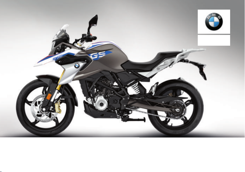
Rider's Manual (US Model)
G 310 GS
BMW Motorrad
Page 2
Motorcycle/Retailer Data
Motorcycle Data
Model
Vehicle identification number
Color number
Initial registration
License plate
Retailer Data
Contact in Service
Ms./Mr.
Phone number
Retailer's address/phone number (company stamp)
Page 3

Welcome to BMW
Congratulations on choosing a
motorcycle from BMW Motorrad
and welcome to the community
of BMW motorcycle owners and
riders. Familiarize yourself with
your new motorcycle so that you
can ride it safely and confidently
in all highway traffic situations.
About this Rider's Manual
Please read this Rider's Manual
carefully before starting to use
your new BMW. It contains important information on how to
operate the controls and how to
get the most benefit from your
BMW's advanced technical features.
In addition, it contains information
on maintenance and care to help
you maintain your motorcycle's
reliability and safety, as well as its
value.
Documentation confirming performance of scheduled maintenance is a precondition for generous handling of out-of-warranty
claims and goodwill warranty
treatment.
Should you want to sell your
BMW one day, please also remember to turn over the Ride's
Manual to the new owner. it is
an important part of your motorcycle.
Suggestions and complaints
If you have any questions concerning your motorcycle, your authorized BMW Motorrad retailer
is always happy to provide advice
and assistance.
We wish you many miles of safe
and enjoyable riding on your
BMW
BMW Motorrad.
01 40 9 480 087
*01409480087*
Page 4

Table of Contents
1 General instructions . ... 5
Quick & easy reference . . . . . . 6
Abbreviations and
symbols .. . . . . . . . . . . . . . . . . . . . . 6
Equipment . . . . . . . . . . . . . . . . . . . 6
Technical Data . . . . . . . . . . . . . . . 7
Notice concerning current sta-
tus . . . . . . . . . . . . . . . . . . . . . . . . . . . 7
2 Overviews . .. .. .. .. . ... .. . 9
General view, left side . . . . . . . 11
General view, right side . . . . . 13
Underneath seat . . . . . . . . . . . . 14
Multifunction switch, left . . . . 15
Multifunction switch,
right . . . . . . . . . . . . . . . . . . . . . . . . . 16
Instrument panel . . . . . . . . . . . . 17
3 Displays . . ... .. .. .. . ... .. 19
Warning and indicator
lights . . . . . . . . . . . . . . . . . . . . . . . . 20
Multifunction display . . . . . . . . 21
Warning lights . . . . . . . . . . . . . . . 22
Service display . . . . . . . . . . . . . . 28
Fuel reserve . . . . . . . . . . . . . . . . . 29
Tachometer . . . . . . . . . . . . . . . . . 29
4 Operation ... .. .. .. .. .. .. . 31
Ignition . . . . . . . . . . . . . . . . . . . . . . 32
Lights . . . . . . . . . . . . . . . . . . . . . . . 34
Turn indicators . . . . . . . . . . . . . . 34
Multifunction display . . . . . . . . 36
Time and date . . . . . . . . . . . . . . 37
Resetting the trip
distance . . . . . . . . . . . . . . . . . . . . . 37
Resetting average data . . . . . . 38
Antilock Brake System
(ABS). . . . . . . . . . . . . . . . . . . . . . . . 38
Seat . . . . . . . . . . . . . . . . . . . . . . . . . 39
5 Setting .. .. .. .. .. . ... .. .. . 41
Mirrors . . . . . . . . . . . . . . . . . . . . . . 42
Headlight . . . . . . . . . . . . . . . . . . . . 42
Spring preload . . . . . . . . . . . . . . 43
6 Riding .. .. .. .. .. . ... .. .. .. 45
Safety information . . . . . . . . . . . 46
Checklist . . . . . . . . . . . . . . . . . . . . 48
Starting. . . . . . . . . . . . . . . . . . . . . . 48
Running in . . . . . . . . . . . . . . . . . . 51
Engine speed warner. . . . . . . . 51
Brakes . . . . . . . . . . . . . . . . . . . . . . 52
Parking your motorcycle . . . . 53
Refueling . . . . . . . . . . . . . . . . . . . . 54
Securing motorcycle for
transport . . . . . . . . . . . . . . . . . . . . 56
7 Technology in
detail .. . ... .. .. .. .. . ... .. . 59
General instructions . . . . . . . . . 60
Anti-Lock Brake System . . . . 60
8 Maintenance . ... .. .. .. .. 63
General instructions . . . . . . . . . 64
Tool kit . . . . . . . . . . . . . . . . . . . . . . 64
Front wheel stand . . . . . . . . . . . 65
Rear-wheel stand . . . . . . . . . . . 66
Engine oil . . . . . . . . . . . . . . . . . . . 67
Brake system . . . . . . . . . . . . . . . 68
Clutch . . . . . . . . . . . . . . . . . . . . . . . 73
Coolant. . . . . . . . . . . . . . . . . . . . . . 74
Rims and tires. . . . . . . . . . . . . . . 76
Wheels . . . . . . . . . . . . . . . . . . . . . . 77
Chain . . . . . . . . . . . . . . . . . . . . . . . . 85
Light sources . . . . . . . . . . . . . . . 87
Page 5

Jump-starting . . . . . . . . . . . . . . . 91
Battery . . . . . . . . . . . . . . . . . . . . . . 92
Fuses . . . . . . . . . . . . . . . . . . . . . . . 95
Diagnostic connector. . . . . . . . 97
9 Accessories . .. .. .. . ... .. 99
General instructions . . . . . . . 100
Heated handlebar grips . . . 100
Power socket . . . . . . . . . . . . . 101
Topcase. . . . . . . . . . . . . . . . . . . 101
Topcase Light. . . . . . . . . . . . . 104
Maximum payload and
maximum speed . . . . . . . . . . 105
10 Care . . ... .. .. .. .. . ... . 107
Care products . . . . . . . . . . . . . 108
Washing your motorcy-
cle. . . . . . . . . . . . . . . . . . . . . . . . . 108
Cleaning sensitive motorcy-
cle parts. . . . . . . . . . . . . . . . . . . 109
Paint . . . . . . . . . . . . . . . . . . . . . . 110
Paint preservation . . . . . . . . . 110
Store motorcycle . . . . . . . . . . 110
Return motorcycle to
use . . . . . . . . . . . . . . . . . . . . . . . . 110
11 Technical data . .. .. . 113
Troubleshooting chart . . . . . 114
Screw connections . . . . . . . . 115
Fuel . . . . . . . . . . . . . . . . . . . . . . . 117
Engine oil . . . . . . . . . . . . . . . . . 117
Engine . . . . . . . . . . . . . . . . . . . . 118
Clutch . . . . . . . . . . . . . . . . . . . . . 119
Transmission . . . . . . . . . . . . . . 119
Rear-wheel drive . . . . . . . . . . 120
Frame . . . . . . . . . . . . . . . . . . . . . 120
Chassis and
suspension . . . . . . . . . . . . . . . . 121
Brakes . . . . . . . . . . . . . . . . . . . . 121
Wheels and tires . . . . . . . . . . 122
Electrical system . . . . . . . . . . 124
Dimensions . . . . . . . . . . . . . . . 125
Weights . . . . . . . . . . . . . . . . . . . 126
Performance data . . . . . . . . . 126
Accessories . . . . . . . . . . . . . . . 126
12 Service . ... .. .. .. .. .. . 127
Reporting safety
defects . . . . . . . . . . . . . . . . . . . . 128
BMW Motorrad Service .. . 129
BMW Motorrad Mobility
Services . . . . . . . . . . . . . . . . . . . 129
Maintenance proce-
dures . . . . . . . . . . . . . . . . . . . . . . 129
Maintenance schedule . . . . 133
Maintenance confirma-
tions. . . . . . . . . . . . . . . . . . . . . . . 134
Service confirmations . . . . . 148
13 Index . .. .. .. .. .. .. .. .. 150
Page 6

Page 7

General instructions
Quick & easy reference . . . . . . . . . . . . . . 6
Abbreviations and symbols . . . . . . . . . . 6
Equipment . . . . . . . . . . . . . . . . . . . . . . . . . . . 6
Technical Data . . . . . . . . . . . . . . . . . . . . . . . 7
Notice concerning current status . . . . 7
1
5
z
General instructions
Page 8
Quick & easy reference
1
This Rider's Manual has been
designed to provide quick and
6
efficient orientation. Go straight
to the "Overviews" chapter if you
would like an initial overview of
your motorcycle.
Abbreviations and symbols
CAUTION Hazard with
low risk. Failure to avoid
this hazard can result in minor or
moderate injury.
WARNING Hazard with
z
General instructions
moderate risk. Failure to
avoid this hazard can result in
death or serious injury.
DANGER Hazard with high
risk. Failure to avoid this
hazard results in death or serious
injury.
ATTENTION Special in-
structions and precautionary measures. Non-compliance
can cause damage to the vehicle or accessories and warranty
claims may be denied as a result.
NOTICE Special informa-
tion on operating and inspecting your motorcycle as well
as maintenance and adjustment
procedures.
Indicates the end of an
item of information.
Instruction.
Result of an activity.
Reference to a page with
more detailed information.
Indicates the end of accessory or equipmentdependent information.
Tightening torque.
Technical data.
ABS Anti-Lock Brake System.
NV National-market version.
OA Optional accessory.
BMW Motorrad optional accessories can
be purchased and installed at your authorized BMW Motorrad
retailer.
Equipment
When you ordered your BMW
motorcycle, you chose various
items of custom equipment. This
rider's manual describes selected
optional accessories (OA) from
BMW. This explains why the
manual may also contain descriptions of equipment which
Page 9

you have not ordered. Please
note, too, that your motorcycle
might not be exactly as illustrated in this manual on account
of country-specific differences.
If your motorcycle comes with
equipment not described here,
you can find the descriptions in a
separate manual.
Technical Data
All dimensions, weights and
power ratings stated in the
rider's manual are quoted to the
standards and comply with the
tolerance requirements of the
Deutsches Institut für Normung
e. V. (DIN). Versions for individual
countries may differ.
Notice concerning current status
The high safety and quality standards of BMW motorcycles are
maintained by constant development work on design, equipment
and accessories. For this reason,
some aspects of your motorcycle
may vary from the descriptions in
this Rider's Manual. In addition,
BMW Motorrad cannot guarantee
the total absence of errors. We
hope you will appreciate that no
claims can be recognized based
on the data, illustrations or descriptions in this manual.
1
7
z
General instructions
Page 10

1
8
z
General instructions
Page 11

Overviews
General view, left side. . . . . . . . . . . . . . . 11
General view, right side . . . . . . . . . . . . . 13
Underneath seat . . . . . . . . . . . . . . . . . . . . 14
Multifunction switch, left . . . . . . . . . . . . 15
Multifunction switch, right . . . . . . . . . . . 16
Instrument panel . . . . . . . . . . . . . . . . . . . . 17
2
9
z
Overviews
Page 12
2
10
z
Overviews
Page 13

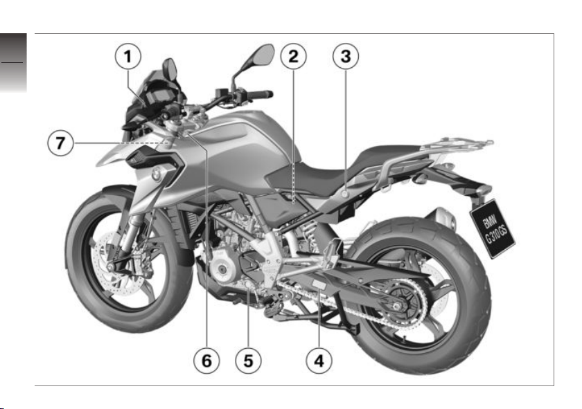
General view, left side
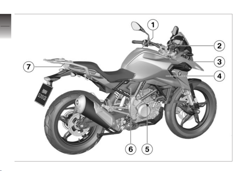
1 with additional onboard
Power socket ( 101)
2 Adjusting ring for spring
preload (behind the frame
cover) ( 43)
3 Seat lock ( 39)
4 Chain adjustment values
( 86)
5 Engine oil level indicator
( 67)
6 Type plate (on the left
steering head)
7 Tire pressure table (on the
left fork leg) ( 76)
socket
OA
2
11
z
Overviews
Page 14
2
12
z
Overviews
Page 15

General view, right side
1 Fuel filler opening ( 55)
2 Brake-fluid reservoir, front
( 71)
3 Vehicle identification num-
ber
4 Coolant expansion tank
( 74)
5 Oil fill location ( 68)
6 Brake fluid reservoir, rear
(behind the frame cover)
( 72)
7 Grab handle ( 46)
2
13
z
Overviews
Page 16
Underneath seat
2
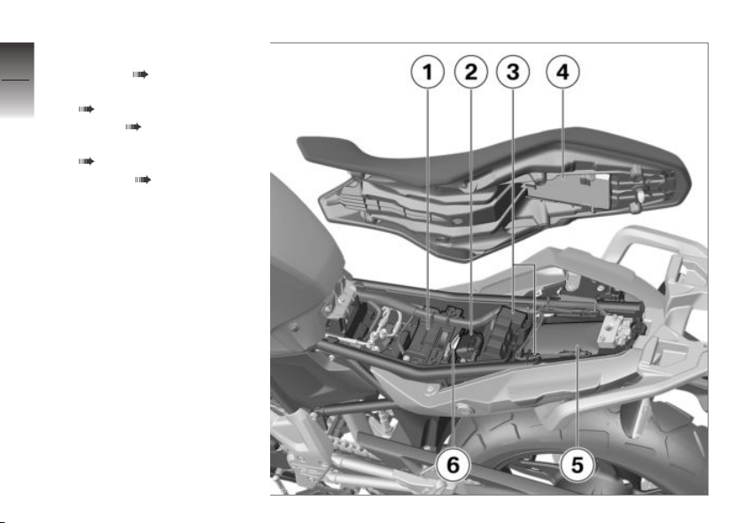
1 Battery ( 92)
2 Data link connector
14
z
Overviews
( 97)
3 Fuses ( 95)
4 Rider's Manual (US Model)
( 6)
5 Tool kit ( 64)
6 Spare fuses
Page 17
Multifunction switch, left
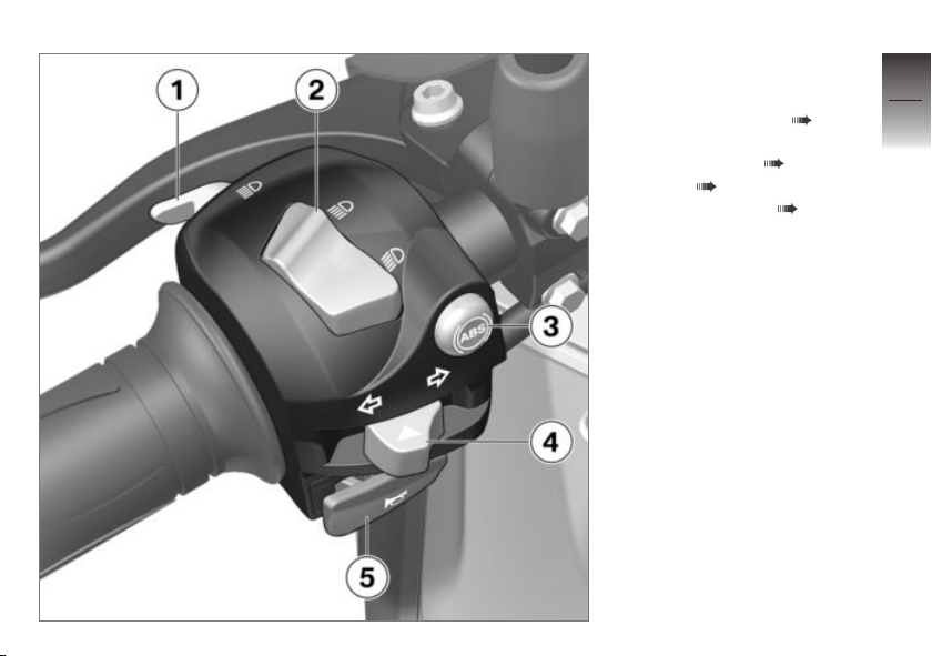
1 Headlight flasher ( 34)
2 High beams/low beams
rocker switch ( 34)
3 ABS ( 38).
4 Turn indicators ( 34)
5 Horn
2
15
z
Overviews
Page 18
Multifunction switch,
2
right
16
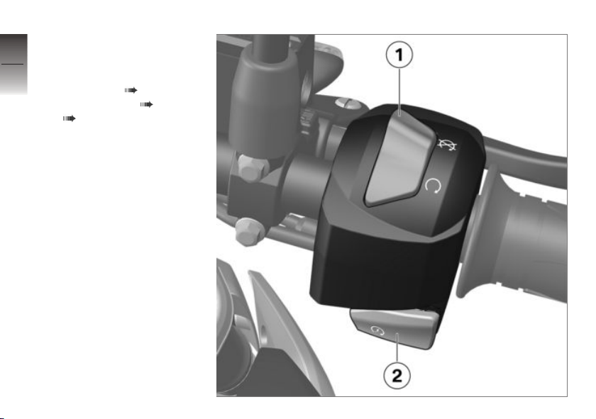
1 Emergency on/off switch
(kill switch) ( 33)
2 Starter button ( 33)
( 48)
z
Overviews
Page 19
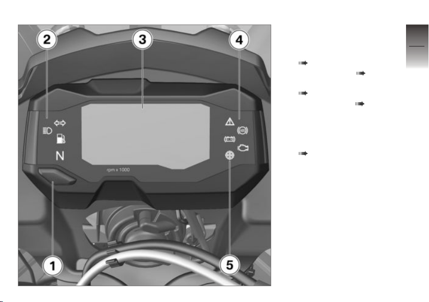
Instrument panel
1 Button
Selecting display readings
( 36).
2 Indicator lights ( 20)
3 Multifunction display
( 21)
4 Warning lights ( 20)
5 Photosensor for brightness
control in the multifunction
display
Engine speed warner
( 51).
2
17
z
Overviews
Page 20

2
18
z
Overviews
Page 21

Displays
Warning and indicator lights. . . . . . . . . 20
Multifunction display . . . . . . . . . . . . . . . . 21
Warning lights . . . . . . . . . . . . . . . . . . . . . . 22
Service display . . . . . . . . . . . . . . . . . . . . . . 28
Fuel reserve . . . . . . . . . . . . . . . . . . . . . . . . 29
Tachometer . . . . . . . . . . . . . . . . . . . . . . . . 29
3
19
z
Displays
Page 22
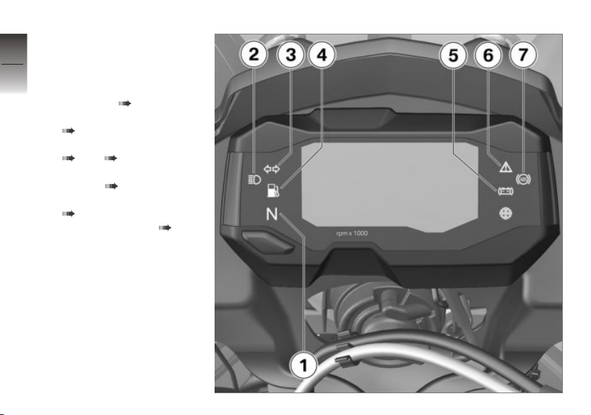
Warning and indicator
3
lights
20
1 Neutral indicator light
2 Headlight high beam indi-
cator light ( 34)
3 Turn signal indicator light
( 34)
4 Low-fuel warning light
( 27) ( 29)
5 Warning light for vehicle
z
Displays
voltage ( 25)
6 General warning light
( 22)
7 ABS warning light ( 26)
Page 23
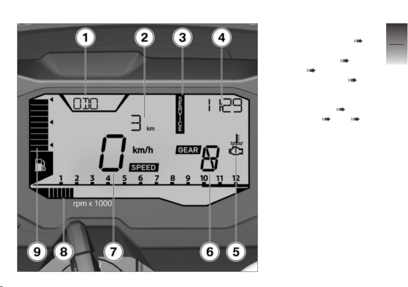
Multifunction display
1 Onboard computer ( 36)
2 Indication range for values
3 Service display ( 28)
4 Time ( 37)
5 Warning symbols ( 22)
6 Gear, "N" indicates neutral
7 Speed
8 Engine speed ( 29)
9 Fuel level ( 27) ( 29)
3
21
z
Displays
Page 24
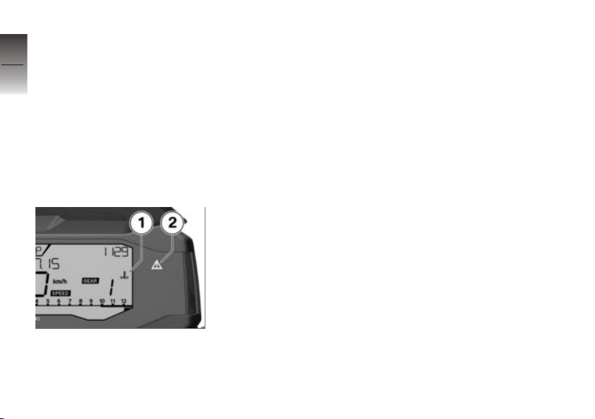
Warning lights
3
Displays
22
Warnings are displayed with appropriate warning lights.
If several warnings are active, all
of the corresponding warning
lamps and warning symbols will
appear in the display.
You will find an overview of the
potential warnings on the following pages.
z
Displays
Warnings for which there are
no separate warning lamps are
represented by a warning symbol 1 in the multifunction display
in connection with the general
warning lamp 2. Depending on
how urgent the warning is, the
general warning lamp will either
light up or flash red or yellow.
Page 25
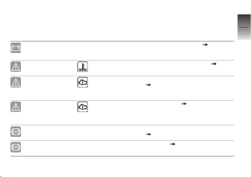
Overview of warning indicators
Indicator and warning
Display text Meaning
lights
Warning lamp for
vehicle voltage
lights up.
General warning
light flashes red.
General warning
light lights up yellow.
General warning
light flashes yellow.
ABS indicator light
flashes.
ABS indicator light
lights up.
Temperature symbol is displayed.
The engine electronics symbol
appears on the
display.
The engine electronics symbol
appears on the
display.
Vehicle voltage is too low ( 25)
Coolant temperature too high ( 25)
Engine in emergency-operation mode
( 25)
Engine warning ( 26)
ABS self-diagnosis not completed
( 26)
ABS error ( 27)
3
23
z
Displays
Page 26
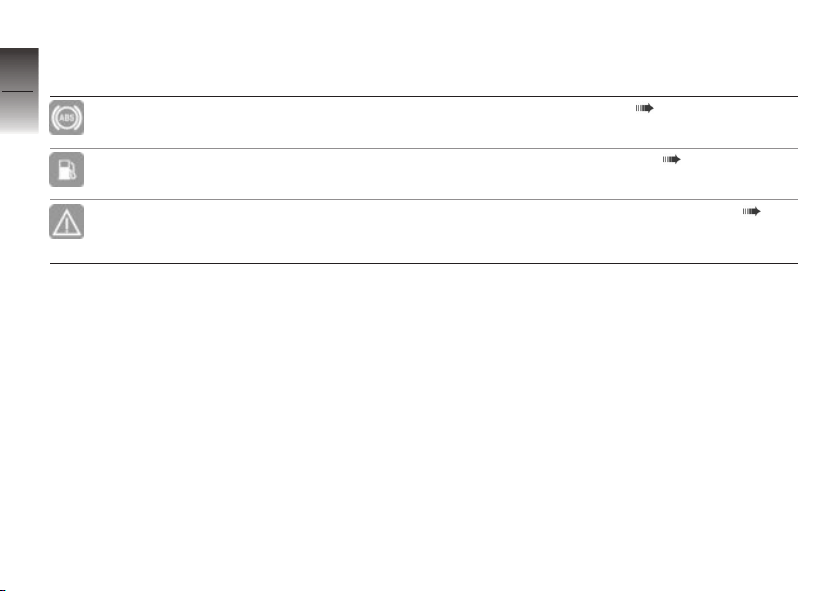
Indicator and warning
3
lights
24
z
Displays
ABS indicator light
lights up.
Low-fuel warning
light lights up.
General warning
light lights up yellow.
Display text Meaning
ABS switched off ( 27)
Fuel down to reserve ( 27)
SERVICE is displayed continuously.
Service appointment has passed ( 28)
Page 27
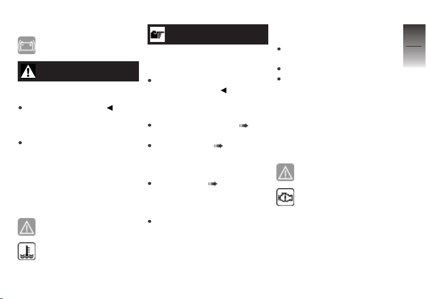
Vehicle voltage is too low
Warning lamp for vehicle
voltage lights up.
WARNING
Failure of vehicle systems
Accident hazard
Do not continue riding.
Possible cause:
Battery is faulty.
Have the malfunction corrected
as soon as possible at an
authorized service facility,
preferably an authorized
BMW Motorrad Retailer.
Coolant temperature too
high
General warning light
flashes red.
Temperature symbol is displayed.
ATTENTION
Riding with overheated engine
Engine damage
Be sure to observe the measures listed below.
Possible cause:
Coolant level is too low.
Checking coolant level ( 74).
If coolant level is too low:
Top up coolant ( 75).
Possible cause:
The radiator is dirty.
Clean radiator ( 109).
Possible cause:
The fan or fan control is faulty.
Have the malfunction corrected
as soon as possible at an
authorized service facility,
preferably an authorized
BMW Motorrad Retailer.
Possible cause:
The coolant circuit is faulty.
If possible, allow the engine to
cool down.
Only ride in partial load range.
If the coolant temperature is often too high, have the fault rectified as soon as possible by a
specialist workshop, preferably
an authorized BMW Motorrad
retailer.
Engine in emergencyoperation mode
General warning light lights
up yellow.
The engine electronics
symbol appears on the
display.
3
25
z
Displays
Page 28
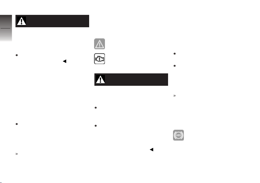
3
26
z
Displays
WARNING
Unusual handling when the
engine is in emergency operation
Accident hazard
Avoid rapid acceleration and
passing maneuvers.
Possible cause:
The engine control unit has diag-
nosed a fault which impairs the
engine performance or throttle
response. The engine is running in the emergency-operation
mode. In exceptional cases, the
engine stops and can no longer
be started.
Have the malfunction corrected
as soon as possible at an
authorized service facility,
preferably an authorized
BMW Motorrad Retailer.
It is possible to continue riding, however the engine performance and engine speed range
may be impaired and not function as normal.
Engine warning
General warning light
flashes yellow.
The engine electronics
symbol appears on the
display.
WARNING
Damage to engine during
emergency operation
Accident hazard
Drive slowly and avoid rapid
acceleration and passing maneuvers.
If possible, have the vehicle
picked up and the fault eliminated at a specialist workshop, preferably an authorized
BMW Motorrad retailer.
Possible cause:
The engine control unit has di-
agnosed a fault, which can lead
to a severe secondary fault. The
engine is in the emergency-operation mode.
Avoid high load and engine
speed ranges if possible.
Have the malfunction corrected
as soon as possible at an
authorized service facility,
preferably an authorized
BMW Motorrad Retailer.
Continued driving is possible, however it is not recommended.
ABS self-diagnosis not
completed
ABS indicator light flashes.
Page 29
Possible cause:
ABS self-diagnosis routine not completed
The ABS function is not
available, as the self-diagnosis
function has not been
completed. (The motorcycle
must reach a specified
minimum speed before the
system can check operation of
the wheel sensors: min 3 mph
(min 5 km/h))
Ride off slowly. It must be
noted that the ABS function
is not available until the selfdiagnosis has been completed.
ABS error
ABS indicator light lights
up.
Possible cause:
The ABS control unit has de-
tected an error. The ABS function is not available at all or is
restricted.
It is possible to continue riding the motorcycle if you make
allowance for the failed or limited ABS function. You should
also take account of the additional information on situations
that can lead to an ABS fault
( 61).
Have the malfunction corrected
as soon as possible at an
authorized service facility,
preferably an authorized
BMW Motorrad Retailer.
ABS switched off
ABS indicator light lights
up.
Possible cause:
The ABS system has been deac-
tivated by the rider.
Activating ABS ( 39).
Fuel down to reserve
Low-fuel warning light lights
up.
WARNING
Rough engine running or
switching off of the engine
due to a fuel shortage
Accident hazard, damage to catalytic converter
Do not drive to the extent that
the fuel tank is completely
empty.
Possible cause:
The fuel has all been used up;
only the fuel reserve remains.
3
27
z
Displays
Page 30
3
28
Fuel reserve
Approx. 1.1 quarts (Approx.
1 l)
Refueling ( 55).
Service appointment has
passed
General warning light lights
z
Displays
up yellow.
SERVICE is displayed continuously.
Possible cause:
The driving performance or the
date indicate that servicing is
due.
Have your motorcycle serviced
regularly by a specialist workshop, preferably an authorized
BMW Motorrad retailer.
The motorcycle remains operationally safe and is suitably
road-safe.
The value of the motorcycle
is preserved to the greatest
possible extent.
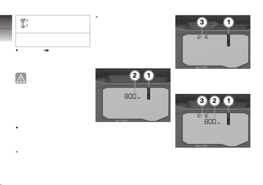
Service display
Remaining distance until
service is due and service
due date
If service is due within 700 miles,
the SERVICE inscription 1 and
the remaining distance covered 2
will be displayed and counted
down in steps of 100 miles. It
is briefly displayed following the
Pre-Ride-Check.
If service is due within a month,
the SERVICE inscription 1 and
the service date 3 are shown.
If service is due because of the
distance covered and the date,
the SERVICE inscription 1, the
remaining distance covered 2
Page 31
and the service date 3 will be
shown.
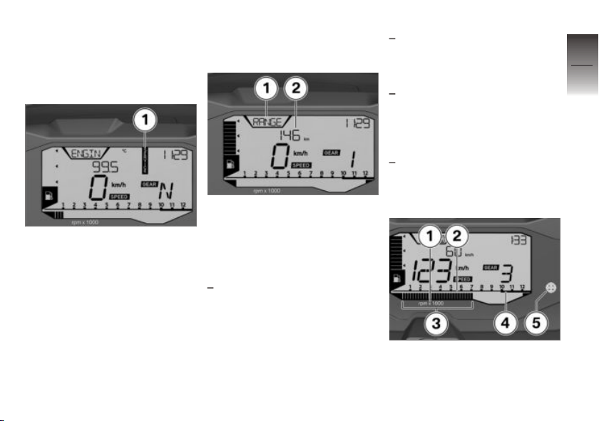
Permanent SERVICE
inscription
If the service appointment is
overdue or the service distance
covered is exceeded, SERVICE 1
will be permanently displayed
during operation.
Fuel reserve
Cruising range
The range RANGE 1 indicates
how far you can ride 2 with the
remaining fuel in the tank. This
distance is calculated based on
fuel quantity and average consumption.
If the motorcycle is standing on
its side stand, the motorcycle's
inclined position will prevent
the fuel level from being registered accurately. This is the
reason why the range is recalculated only when the side
stand is folded in.
The travel range automatically
appears in the multifunction
display after the fuel reserve
level is reached.
After a refueling stop, the
range is recalculated if the
quantity of fuel in the tank
is greater than the reserve
quantity.
The determined range is an
approximate reading.
Tachometer
1 Unit for tachometer:
1000 revolutions per
minute
3
29
z
Displays
Page 32

2 Low engine speed range
3 Segments for tachometer
3
4 High engine speed range
30
5 Engine speed warner
( 51).
z
Displays
Page 33

Operation
Ignition. . . . . . . . . . . . . . . . . . . . . . . . . . . . . . 32
Lights . . . . . . . . . . . . . . . . . . . . . . . . . . . . . . . 34
Turn indicators . . . . . . . . . . . . . . . . . . . . . . 34
Multifunction display . . . . . . . . . . . . . . . . 36
Time and date . . . . . . . . . . . . . . . . . . . . . . 37
Resetting the trip distance . . . . . . . . . . 37
Resetting average data . . . . . . . . . . . . . 38
Antilock Brake System (ABS) . . . . . . . 38
Seat . . . . . . . . . . . . . . . . . . . . . . . . . . . . . . . . 39
4
31
z
Operation
Page 34
Ignition
4
Vehicle keys
32
You are provided with 2 vehicle
keys.
A single key fits the steering and
ignition lock, the fuel filler cap
and the seat lock.
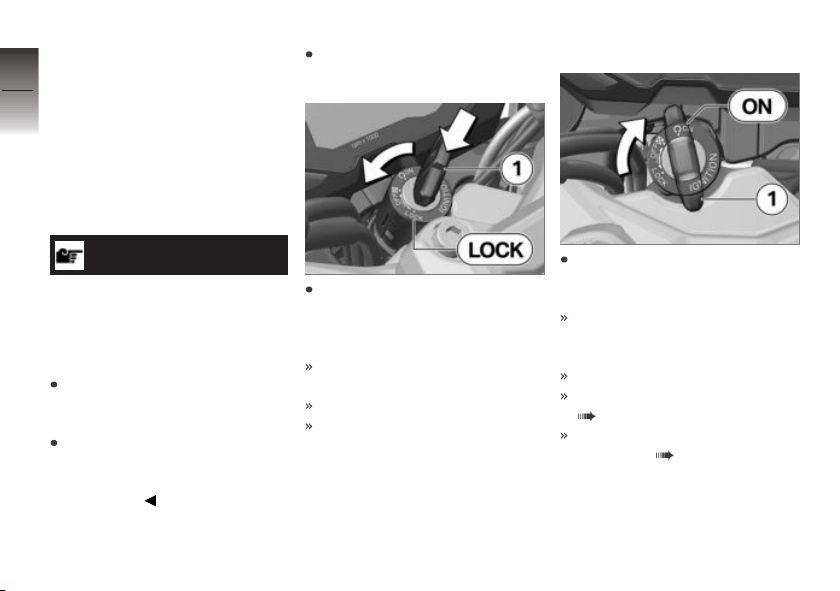
Locking handlebars
If the slope of the road permits,
turn the handlebars to the left.
Switching on ignition
ATTENTION
z
Operation
Handlebars turned in wrong
direction when motorcycle
propped on side stand.
Component damage cause by
tipping over
On level ground, always turn
the handlebars to the left to set
the steering lock.
Otherwise the angle of the
ground determines whether
the handlebars are set to the
left or right.
Push the ignition key 1 into
the steering lock and turn to
the LOCK position while moving the handlebars slightly.
Ignition, lights and all electrical
circuits are switched off.
Handlebars are locked.
The vehicle key can now be
removed.
Insert ignition key 1 into ignition switch/steering lock and
turn to the ON position.
Parking lights, lowbeam headlight, and all functional circuits
are switched on.
Engine can be started.
Pre-Ride-Check is carried out.
( 49)
ABS self-diagnosis is
performed ( 50)
Page 35
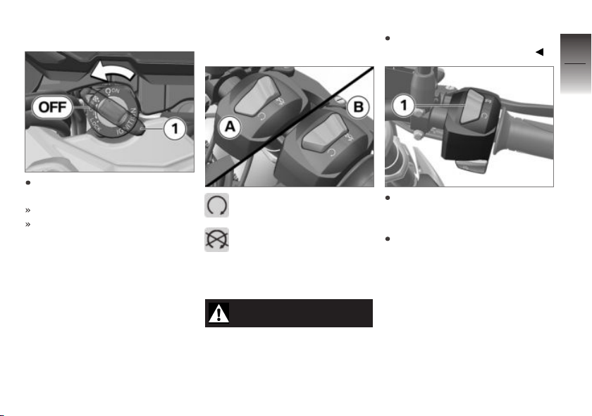
Switch off ignition
Turn the ignition key 1 to
the OFF position.
Handlebars are not locked.
The vehicle key can now be
removed.
Emergency on/off switch
(kill switch)
A = Operation mode
B = Emergency off (engine
is off)
Emergency off or
operation mode
WARNING
Operation of the emergency
ON/OFF switch when riding
Danger of falling due to blocking
of rear wheel
Do not operate the emergency
ON/OFF switch when riding.
Push the emergency off
switch 1 forwards to turn off
the engine quickly and easily.
Push the emergency off
switch 1 back to start the
engine.
4
33
z
Operation
Page 36
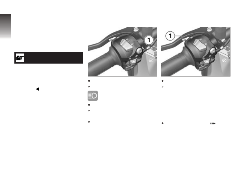
Lights
4
Low-beam headlight and
34
parking lights
The low beam and parking lamps
turn on automatically when the
ignition is switched on.
NOTICE
The low beam and the parking
lamps drain the battery. Do
not leave the ignition switched
z
Operation
on longer than absolutely
necessary.
Operating high-beam
headlight
Press switch 1 forwards.
High beams are switched on.
High beam indicator light
lights up.
Press switch 1 backwards.
The blue high beam indicator
light goes out.
Low beams are switched on.
Operating headlight
flasher
Press button 1.
The high beams are switched
on for the duration of the operation.
Turn indicators
Operating turn signals
Switching on ignition ( 32).
Page 37
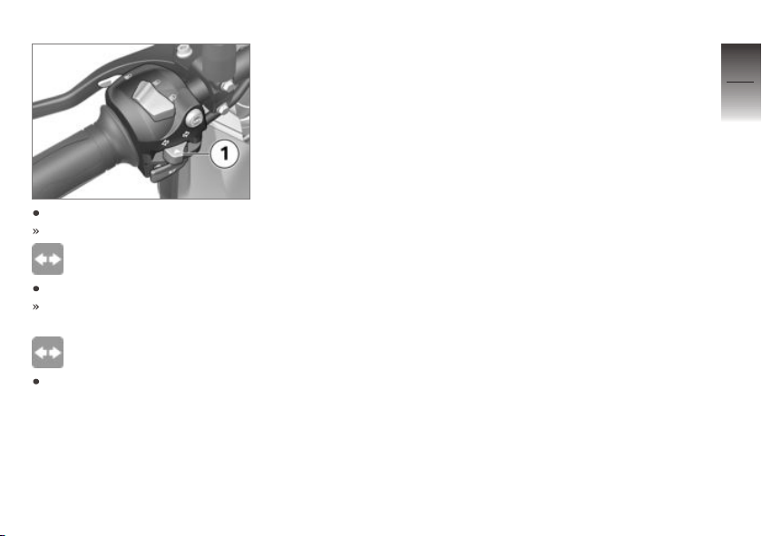
Press switch 1 to left.
Left turn signal is turned on.
Indicator light of turn indicator flashes.
Press switch 1 to right.
Right turn signal is switched
on.
Indicator light of turn indicator flashes.
Press switch 1 into center position to turn off turn signals.
4
35
z
Operation
Page 38
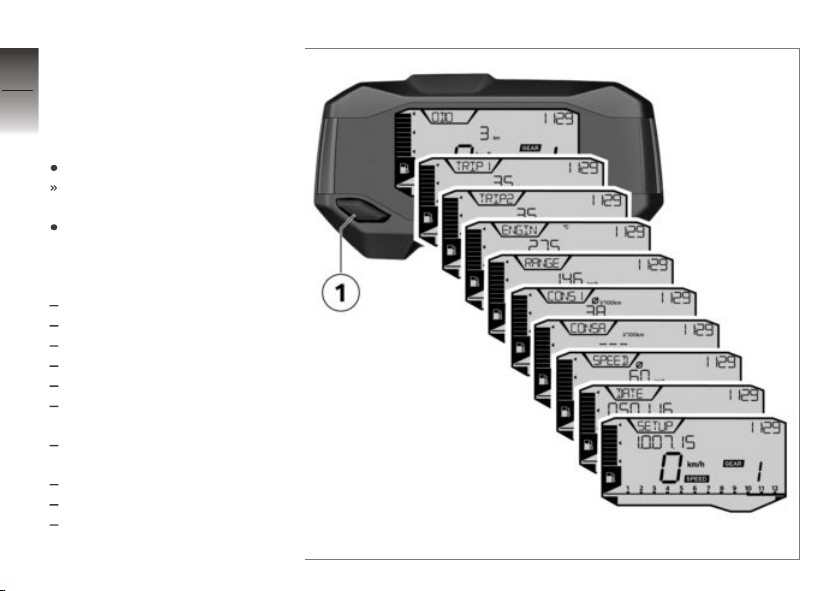
Multifunction display
4
Selecting display readings
36
Requirement
The motorcycle is stopped.
Switch on the ignition.
The onboard computer is displayed.
Press the button 1 briefly and
repeatedly until the desired
value is displayed.
z
Operation
Possible displays:
Total distance traveled: ODO
Trip distance 1: TRIP1
Trip distance 2: TRIP2
Coolant temperature: ENGIN
Range: RANGE
Average fuel consumption:
CONS1
Current fuel consumption:
CONSA
Average speed: SPEED
Date: DATE
Settings: SETUP
Page 39
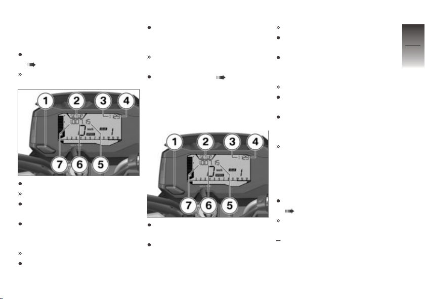
Time and date
Set clock
Selecting display readings
( 36).
SETUP 2 is displayed.
When the minutes have been
set as desired, press and hold
button 1.
The time has not yet been
saved!
Setting the date ( 37).
Setting the date
Requirement
Clock has been set.
Day 6 flashes.
Briefly press button 1 to increment the day.
When the day has been set as
desired, press and hold button 1.
Year 5 flashes.
Briefly press the button 1 to
increment the year.
When the year has been set
as desired, press and hold button 1.
The clock and date settings
have been saved.
4
37
z
Operation
Press and hold button 1.
The hours 3 flash.
Briefly press button 1 to increment the hours 3.
When the hours have been set
as desired, press and hold button 1.
The minutes 4 flash.
Briefly press button 1 to increment the minutes.
Briefly press button 1 to increment the month 7.
When the month has been set
as desired, press and hold button 1.
Resetting the trip distance
Selecting display readings
( 36).
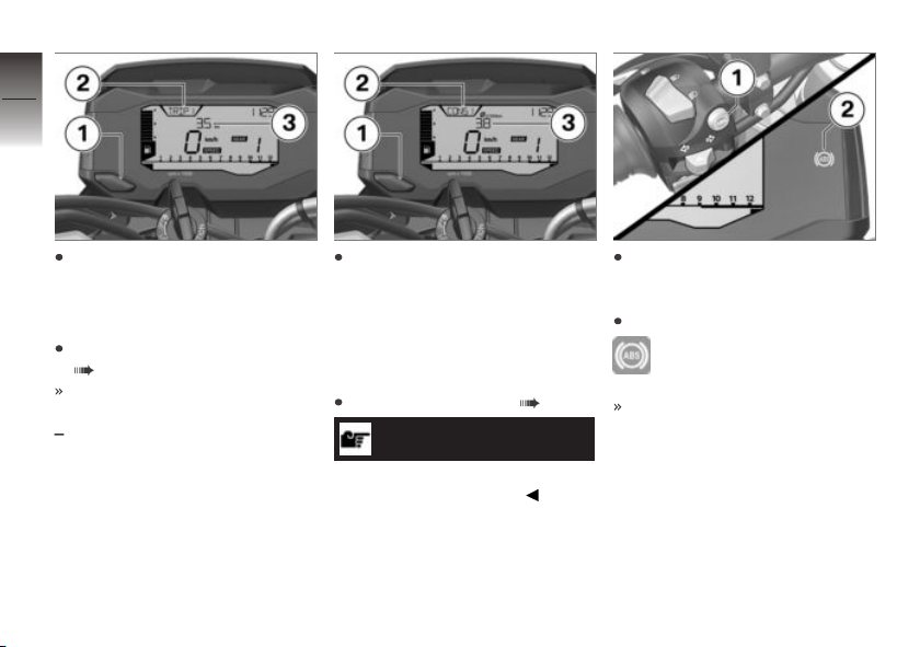
The trip distance to be reset 2
was selected.
"TRIP1" or "TRIP2" is indicated.
Page 40
4
38
Press and hold button 1 until
the value 3 has been reset.
z
Operation
Resetting average data
Selecting display readings
( 36).
The average value to be reset 2 was selected.
"CONSI" or "SPEED" is indicated.
Press and hold button 1 until
the value 3 has been reset.
Antilock Brake System (ABS)
Deactivate ABS
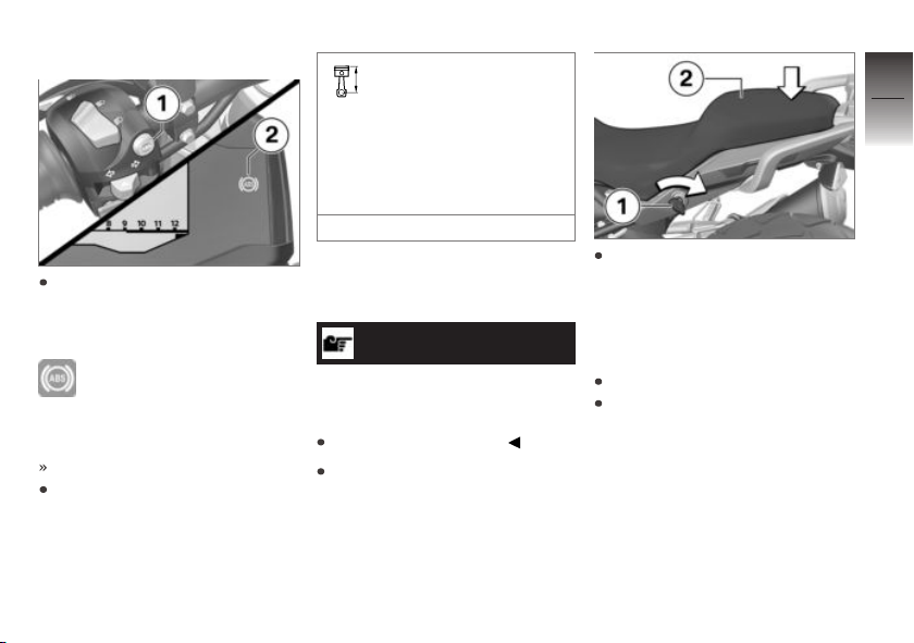
Switching on ignition ( 32).
NOTICE
The ABS function can also be
deactivated while driving.
Press and hold button 1 until
the ABS indicator and warning
light lights up.
Release button 1.
ABS indicator light lights
up.
ABS is deactivated.
Page 41
Activating ABS
Press and hold button 1 until
the ABS indicator and warning
light 2 changes its display behavior.
ABS indicator light goes
out, and starts to flash if
self-diagnosis has not been completed.
ABS is switched on.
As an alternative, the ignition
can also be turned off and then
on again.
If the ABS indicator and
warning light lights up
after switching the ignition off
and on and then continuing
driving above the minimum
speed, an ABS fault has occurred.
min 3 mph (min 5 km/h)
Seat
Removing seat
ATTENTION
Unstably parked motorcycle
Component damage cause by
tipping over
Park motorcycle safely.
Park motorcycle, ensuring that
support surface is firm and
level.
Push down on the rear part of
the seat 2 to relieve the strain
on the lock and at the same
time unlock the seat lock with
the vehicle key 1 by turning it
clockwise.
Lift seat at rear and remove.
Lay the seat on a clean surface.
4
39
z
Operation
Page 42
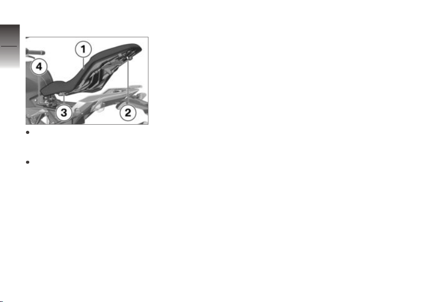
Install seat
4
40
Insert seat 1 with the mount 3
centered into the battery
z
Operation
tray 4.
Put on detent pin 2 and press
into the locking mechanism.
Page 43

Setting
Mirrors . . . . . . . . . . . . . . . . . . . . . . . . . . . . . . 42
Headlight . . . . . . . . . . . . . . . . . . . . . . . . . . . 42
Spring preload . . . . . . . . . . . . . . . . . . . . . . 43
5
41
z
Setting
Page 44
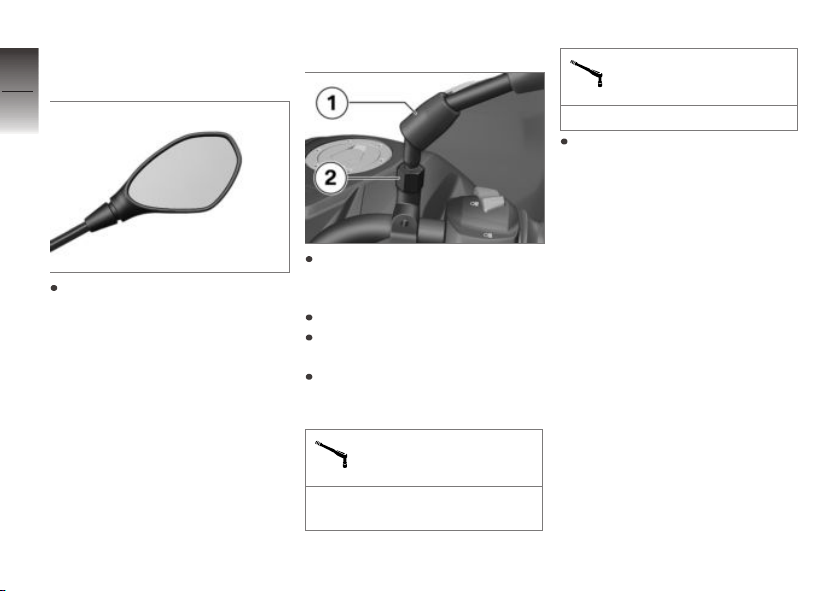
Mirrors
5
Adjusting mirrors
42
z
Setting
Move mirror to the desired position by turning it.
Adjust mirror arm
Slide up protective cap 1 for
threaded connection on mirror
arm.
Loosen lock nut 2.
Turn mirror arm into desired
position.
Tighten lock nut to specified
torque while holding mirror arm
in place.
Right mirror (lock nut) to
adapter
16 lb/ft (22 Nm) (Left-hand
thread)
Left mirror (lock nut) to
adapter
16 lb/ft (22 Nm)
Slide protective cap 1 over
screw fitting.
Headlight
Adjusting headlight for
RHD/LHD traffic
This motorcycle's headlight features a symmetrical low beam.
No special adjustments or procedures are required prior to operating the motorcycle in a country where traffic travels on the
side of the road opposite to that
of your home country (left-hand
drive to right-hand drive or vice
versa).
Page 45
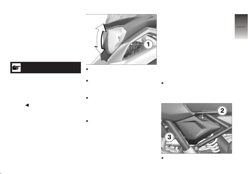
Headlamp range and
spring preload
The headlight range generally
remains constant due to the adjustment of the spring preload to
the loading state. The headlight
range is correctly adjusted at the
factory.
NOTICE
If there are doubts as to the correct headlight range, have the
adjustment checked by a specialized workshop, preferably by
an authorized BMW Motorrad
retailer.
Headlight range
adjustment
Requirement
Despite adjustment of the spring
preload, oncoming traffic is still
blinded when the vehicle is heavily loaded.
Loosen the screw 1 on both
sides.
Turn the headlamp around the
screw axis to set the headlamp
range.
Tighten the screw 1 on both
sides.
If the motorcycle is ridden again
with lower payload:
Readjust the headlamp range.
Spring preload
Setting
The spring preload must be
adjusted to the weight of the
rider, passenger and load. Higher
weight requires a higher spring
preload, lower weight requires a
lower spring preload.
Adjusting spring preload
at rear wheel
Park motorcycle, ensuring that
support surface is firm and
level.
Remove the screw 2.
5
43
z
Setting
Page 46
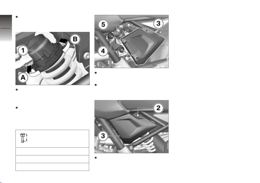
Pull frame cover 3 out of the
grommets and take off.
5
44
z
Setting
To increase the spring preload,
turn adjustment ring 1 in direction A using the vehicle tools.
To decrease the spring
preload, turn adjustment ring 1
in direction B using the vehicle
tools.
Basic setting of spring
preload, rear
Stage 1 (One-up without load)
Stage 5 (One-up with load)
Stage 10 (Two-up and load)
Insert frame cover 3 into grommets 4.
Align frame cover 3 with pushin nut 5.
Install screw 2.
Page 47

Riding
Safety information . . . . . . . . . . . . . . . . . . 46
Checklist . . . . . . . . . . . . . . . . . . . . . . . . . . . . 48
Starting . . . . . . . . . . . . . . . . . . . . . . . . . . . . . 48
Running in . . . . . . . . . . . . . . . . . . . . . . . . . . 51
Engine speed warner . . . . . . . . . . . . . . . 51
Brakes . . . . . . . . . . . . . . . . . . . . . . . . . . . . . . 52
Parking your motorcycle . . . . . . . . . . . . 53
Refueling . . . . . . . . . . . . . . . . . . . . . . . . . . . 54
Securing motorcycle for trans-
port . . . . . . . . . . . . . . . . . . . . . . . . . . . . . . . . . 56
6
45
z
Riding
Page 48
Safety information
6
Rider's Equipment
46
Do not drive without the correct
clothing:
Helmet
Rider's suit
Gloves
Boots
This applies even to short
z
Riding
journeys, and to every season
of the year. Your authorized
BMW Motorrad Retailer will be
happy to advise you and has
the correct clothing for every
purpose.
Load
WARNING
Reduced riding stability
caused by overloading and
uneven loading
Accident hazard
Do not exceed the gross
weight limit and observe the
loading information.
Adjust spring preload settings
to the gross vehicle weight.
with topcase
or
with topcase Light
Observe the maximum pay-
load and maximum speed as
indicated on the label in the
topcase (see also the chapter
"Accessories").
Make sure that weight is uniformly distributed between
right and left.
Store heavy pieces of luggage
below.
OA
OA
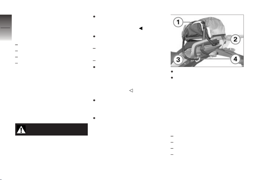
Securely lash down luggage 1.
Thread the straps 2 through
the eyes 4 of the luggage
rack 3 and tighten.
Speed
If you ride at high speed, always
bear in mind that various boundary conditions can adversely affect the handling of your motorcycle:
Wrong spring system setting
Unevenly distributed load
Loose clothing
Insufficient tire inflation pressure
Page 49
Tire tread in poor condition
Etc.
Maximum speed
DANGER
Maximum speed of the motorcycle is higher than the
permissible maximum rated
speed of the tires.
Risk of accident due to tire damage at high speed.
Observe the maximum permissible speed for the tyres.
Risk of poisoning
Exhaust fumes contain carbon
monoxide, which is colorless and
odorless but highly toxic.
WARNING
Harmful exhaust gas
Danger of suffocation
Do not inhale exhaust fumes.
Do not run the engine in
closed rooms.
Burn hazard
CAUTION
Intense heating up of engine
and exhaust system while
riding
Burn hazard
After parking the motorcycle,
make sure that no persons
or objects come into contact
with the engine and exhaust
system.
Catalytic converter
If misfiring causes unburned fuel
to enter the catalytic converter,
there is a danger of overheating
and damage.
For this reason, observe the following points:
Do not run the fuel tank dry.
Do not remove the spark plug
connector while the engine is
running.
Stop the engine immediately if
it misfires.
Use unleaded fuel only.
Comply with all specified maintenance intervals.
ATTENTION
Unburned fuel in the catalytic
converter
Damage to catalytic converter
Note the points listed for
protection of the catalytic
converter.
Danger of overheating
ATTENTION
Engine idling for a lengthy
period while at a standstill
6
47
z
Riding
Page 50
Overheating due to insufficient
cooling; in extreme cases vehicle
6
fire
48
Do not allow the engine to idle
unnecessarily.
After starting, ride off
immediately.
Modifications
z
Riding
ATTENTION
Modifications to the motorcycle (e.g. engine control
unit, throttle valves, clutch)
Damage to the affected parts,
failure of safety-relevant functions, expiration of warranty
Do not make any
modifications.
Checklist
Observe checklist
Use the following checklist to
check your motorcycle at regular intervals.
Always before riding off
Check brake operation ( 68).
Check that the lights and signaling equipment function.
Check clutch function ( 73).
Check tire tread depth ( 76).
Checking tyre pressure ( 76).
Check that the luggage is secure.
At every third refueling
stop
Checking the engine oil level
( 67).
Check front brake pad thickness ( 69).
Check rear brake pad thickness
( 70).
Checking front brake fluid level
( 71).
Checking rear brake fluid level
( 72).
Checking coolant level ( 74).
Lubricate chain ( 86).
Check chain tension ( 86).
Starting
Starting engine
Switch on the ignition.
Pre-Ride-Check is carried out.
( 49)
ABS self-diagnosis is
performed ( 50)
Shift to neutral.
Idle mode indicator
lamp lights up.
Idle mode appears on the
display.
Alternatively: when the gear is
engaged, pull the clutch.
NOTICE
You cannot start the motorcycle
with the side stand extended and
a gear engaged. The engine will
switch itself off if it is started with
the transmission in neutral and
then a gear is engaged before
retracting the side stand.
Page 51
NOTICE
If the throttle grip is actuated too
strongly, the engine will not start
or the current to the starter will
be interrupted. Keep the throttle grip closed or only actuate it
slightly.
For cold starts and at low ambient temperatures: pull lever
to disengage clutch and twist
throttle grip slightly.
Set the emergency-off
switch 1 to operation.
Switch is in operation
mode.
Press the starter button 2.
Engine starts.
Consult the troubleshooting
chart if the engine refuses to
start. ( 114)
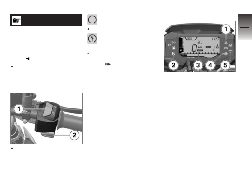
Pre-Ride-Check
After the ignition is switched on,
the instrument cluster runs a
test on the warning and indicator lights and the display, known
as the "Pre-Ride-Check". Starting the engine before the test
routine is completed will cancel
the remainder of the routine.
Phase 1
The general warning light 1 lights
up red.
The indicator lights 2 light up.
The display 3 shows the last active display.
The engine speed warner 4
lights up.
The warning lights 5 light up.
Phase 2
The general warning light 1
changes from red to yellow.
6
49
z
Riding
Page 52

Phase 3
6
The warning and indicator lights
and the engine speed warner go
50
out or adopt their functions for
the operation.
If the service is due, this is displayed for a short time.
If one of the warning and indicator lights is not displayed:
z
Riding
WARNING
Defective warning lights
Lack of display of malfunctions
Check the display of all indicator and warning lights.
Have the malfunction corrected
as soon as possible at an
authorized service facility,
preferably an authorized
BMW Motorrad Retailer.
ABS self-diagnosis
The self-diagnosis routine
is determining whether
BMW Motorrad ABS is ready for
operation. The self-diagnosis
routine launches automatically
when you switch on the ignition.
Phase 1
Check on system components
monitored by diagnostic system while motorcycle is parked.
ABS indicator light flashes.
Phase 2
Check wheel sensors while
starting off.
ABS indicator light flashes.
ABS self-diagnosis
completed
The ABS indicator and warning
light goes out.
ABS self-diagnosis routine not completed
The ABS function is not
available, as the self-diagnosis
function has not been
completed. (The motorcycle
must reach a specified
minimum speed before the
system can check operation of
the wheel sensors: min 3 mph
(min 5 km/h))
If an ABS error is displayed after
the ABS self-diagnosis is completed:
It remains possible to continue
riding. Bear in mind that neither the ABS function nor the
integral function is available.
Have the malfunction corrected
as soon as possible at an
authorized service facility,
preferably an authorized
BMW Motorrad Retailer.
Page 53
Running in
Engine
In the period preceding the
initial inspection attempt to
change rpm and engine load as
frequently as possible, avoiding
extended periods at constant
rpm.
Choose curvy, slightly hilly sections of road if possible.
Observe the engine run-in
speeds.
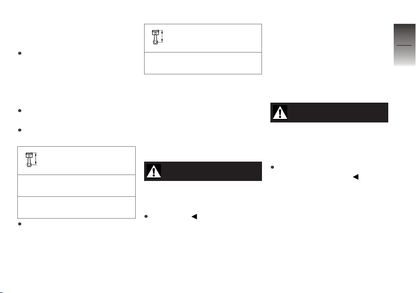
Engine run-in speed
<6000 min-1(Mileage
0...186 miles (0...300 km))
no full throttle (Mileage
0...621 miles (0...1000 km))
Observe mileage, after which
the running-in check should be
performed.
Mileage until running-in
check
311...746 miles
(500...1200 km)
Brake pads
New brake pads have to bedded
in before they can achieve their
optimum frictional force. This initial reduction in braking efficiency
can be compensated for by exerting greater pressure on the
brake levers.
WARNING
New brake pads
Extension of the braking distance,
accident hazard
Brake early.
Tyres
New tires have a smooth surface. This must be roughened
by riding in a restrained manner
at various lean angles until the
tires are run in. Only once the
surface has been roughened can
the tires achieve maximum grip.
WARNING
Loss of adhesion of new tires
on wet roads and at extreme
angles
Accident hazard
Always think well ahead and
avoid extreme angles.
Engine speed warner
Requirement
The vehicle is not yet in 6th gear
and the maximum acceleration is
to be reached.
6
51
z
Riding
Page 54
6
52
Accelerate.
z
Riding
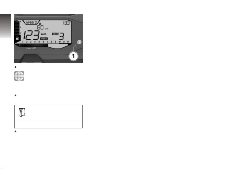
The engine speed warner 1
lights up when the following
engine speed is reached:
>10000 min
Ensure that the following
speed is not exceeded:
Maximum engine speed
max 10800 min
Shift up to the next gear.
Brakes
How do you achieve
the shortest stopping
distances?
The dynamic load distribution between the front and rear wheel
changes during braking. The
heavier you brake, the greater
the weight transfer to the front
wheel. Increases in the load on
an individual wheel are accompanied by a rise in the effective
-1
-1
braking force that the wheel can
provide.
To achieve the shortest braking
distance, the front wheel brake
must be rapidly pulled to the
point where ABS activates, the
pressure point must be held and
the rear wheel brake must be activated at the same time. This
procedure provides ideal exploitation of the extra weight transfer
to the front wheel. The clutch
should also be disengaged at the
same time.
Locking up of the front wheel
is prevented by BMW Motorrad
ABS.
With the frequently instructed
"forced braking," in which the
brake pressure is generated as
quickly as possible and with great
force, dynamic load distribution lags behind the progressive increases in deceleration
rate and the braking force cannot
be completely transferred to the
road surface. Due to the missing wheel load, the ABS must
prevent a tendency of the front
wheel to lock up even with minimal braking action. This results
in a reduced braking action.
Page 55
Descending mountain
passes
WARNING
Braking only with the rearwheel brake when descending mountain passes
Reduced of braking action, destruction of the brakes caused by
overheating
Use both front and rear brakes,
and make use of the engine's
braking effect as well.
Wet, soiled brakes
Moisture and dirt on the brake
rotors and the brake pads result
in a decrease in the braking action.
Delayed or poorer braking action
must be expected in the following situations:
When driving in the rain and
through puddles.
After washing the motorcycle
When driving on roads spread
with salt.
After working on the brakes
due to oil or grease residues.
When driving on soiled roads
or off-road
WARNING
Poorer braking action due to
moisture and dirt
Accident hazard
Brake until brakes are dry or
clean; clean if necessary.
Brake early until the full braking
action is available again.
Parking your motorcycle
Side stand
Switch off engine.
On slopes point the motorcycle
uphill and engage 1st gear.
ATTENTION
Poor ground conditions in
area of stand
Component damage cause by
tipping over
Always check that the ground
under the stand is level and
firm.
Fold out side stand and park
motorcycle.
ATTENTION
Loading of the side stand
with additional weight
Component damage cause by
tipping over
6
53
z
Riding
Page 56
Do not sit on the motorcycle
when it is parked on the side
6
stands.
54
If the slope of the road permits,
turn the handlebars to the left.
Center stand
with center stand
Switch off engine.
z
Riding
ATTENTION
Poor ground conditions in
area of stand
Component damage cause by
tipping over
Always check that the ground
under the stand is level and
firm.
ATTENTION
Center stand folds if subject
to sharp movements.
Component damage cause by
tipping over
OA
Do not sit on the motorcycle
while it is resting on the center
stand.
Fold out center stand and jack
up motorcycle.
On slopes point the motorcycle
uphill and engage 1st gear.
Refueling
Fuel specifications
Requirement
For optimum fuel consumption,
fuel should be sulfur-free or with
the lowest sulfur content possible.
ATTENTION
Refueling with leaded fuel
Damage to catalytic converter
Do not refuel with leaded gasoline or gasoline with metallic
additives, e.g. manganese or
iron.
ATTENTION
Use of Ethanol E85 as fuel
Damage to the engine and fuel
supply
Do not refuel with E85, i.e.
fuel with an ethanol content
of 85 %, or with Flex Fuel.
Check the fuel grade.
Recommended fuel quality
Normal unleaded (max. 10 %
ethanol, E10)
87 AKI (91 ROZ/RON)
87 AKI
Page 57
Refueling procedure
WARNING
Fuel is highly flammable
Fire and explosion hazard
Do not smoke. Never bring
a naked flame near the fuel
tank.
ATTENTION
Component damage
Component damage due to overfilled fuel tank
If the fuel tank is overfilled, the
excess fuel will flow into the
carbon canister and lead to
component damage there.
Only fill the fuel tank to the
lower edge of the fuel filler
neck.
ATTENTION
Contact of fuel and plastic
surfaces
Damage to surfaces (become
unattractive or cloudy)
Immediately clean plastic surfaces after contact with fuel.
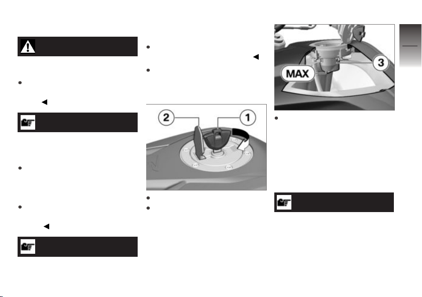
Make sure ground is level and
firm and place motorcycle on
side stand.
Open protective cap 2.
Unlock fuel-tank cap 1 with ignition key by turning clockwise,
then swivel it up.
Refuel with a fuel quality meeting the specifications listed
above, continuing until fuel is
no higher than lower edge of
filler neck 3. While doing so,
pay attention to the bridge in
the filler neck and use caution
so that file does not spray out.
NOTICE
When refueling after running on
fuel reserve, the resulting total
fuel quantity must be greater
than the fuel reserve, so that the
new filling level is detected and
6
55
z
Riding
Page 58
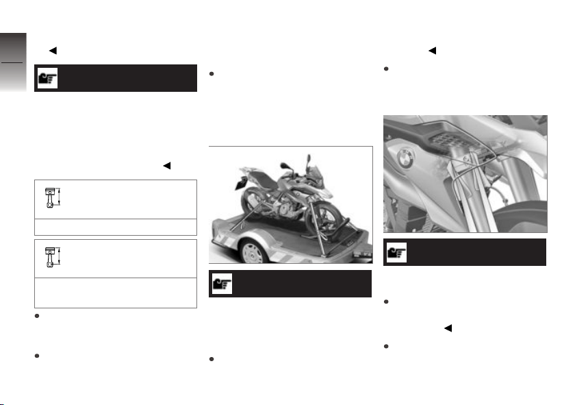
the fuel warning light is switched
off.
6
56
z
Riding
NOTICE
The "usable fuel quantity" specified in the technical data is the
fuel quantity, which can be refueled if the fuel tank was completely emptied, i.e., if the engine
dies off due to lack of fuel.
Usable fuel quantity
Approx. 2.9 gal (Approx. 11 l)
Fuel reserve
Approx. 1.1 quarts (Approx.
1 l)
Unlock fuel tank cap 1 with ignition key by turning clockwise
and close with firm pressure.
Remove vehicle key and close
protective cap.
Securing motorcycle for transport
Protect against scratching all
components where tensioning
straps are routed. For example, use adhesive tape or soft
cloths.
ATTENTION
Motorcycle tips to the side
when raising
Component damage cause by
tipping over
Secure the motorcycle against
tipping to the side, preferably
with the assistance of a second
person.
Push motorcycle onto transport
surface, and do not place on
side stand.
ATTENTION
Pinching of components
Component damage
Do not pinch components,
e.g. brake lines or wiring
harnesses.
Lay straps at front over lower
fork bridge on both sides.
Page 59
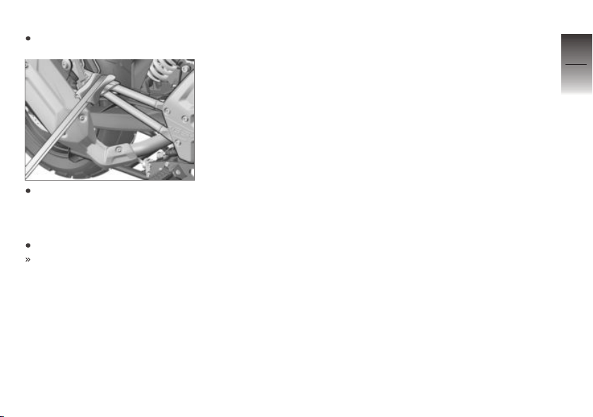
Tension straps downward.
Fasten rear straps on both
sides to the brackets for the
passenger footrests and then
tighten them.
Tighten all straps evenly.
The vehicle is pulled down
against its springs with the
suspension compressed
strongly.
6
57
z
Riding
Page 60

6
58
z
Riding
Page 61

Technology in detail
General instructions . . . . . . . . . . . . . . . . . 60
Anti-Lock Brake System . . . . . . . . . . . . 60
7
59
z
Technology in detail
Page 62

General instructions
7
You'll find more information on
the subject of technology at:
60
bmw-motorrad.com/technik
Anti-Lock Brake System
How does the ABS work?
The maximum braking force that
can be transferred to the road
surface is partially dependent on
the friction coefficient of the road
surface. Gravel, ice, snow and
wet roads offer a considerably
poorer friction coefficient than a
dry, clean asphalt surface. The
z
Technology in detail
poorer the friction coefficient of
the road surface is, the longer
the braking distance will be.
If the maximum transferable
brake force is exceeded when
the driver increases the brake
pressure, the wheels begin
to lock and driving stability is
lost. A fall can occur. Before
this situation can occur, ABS
intervenes and adapts brake
pressure to the maximum
transferable brake force, so the
wheels continue to turn and
driving stability is maintained
irrespective of the condition of
the road surface.
What happens when
rough roads are
encountered?
Bumpy or rough roads can briefly
lead to a loss of contact between
the tires and the road surface,
until the transferable braking
force is reduced to zero. If braking is carried out in this situation, ABS must reduce the brake
pressure to ensure driving stability when restoring contact to the
road. At this point in time, the
ABS must assume extremely low
friction coefficients (gravel, ice,
snow) so that the running wheels
turn in every imaginable case and
the driving stability is ensured.
After detecting the actual conditions, the system adjusts the
optimum brake pressure.
Lifting off rear wheel
Even during severe braking, a
high level of tire grip can mean
that the front wheel does not
lock up until very late, if at all.
Consequently, ABS does not intervene until very late, if at all.
Under these circumstances the
rear wheel can lift off the ground,
and the outcome can be a highsiding situation in which the motorcycle can flip over.
Page 63
WARNING
Lifting off of the rear wheel
due to heavy braking
Accident hazard
When braking heavily, bear in
mind that the ABS control cannot always be relied on to prevent the rear wheel from lifting
off the ground.
Special situations
To detect the tendency of the
wheels to lock up, the speeds
of the front and rear wheel are
compared. If the system registers implausible data for an extended period of time it will deactivate the ABS as safety precaution and a display will alert
you to an ABS error. A self-diagnosis routine must be completed
before the error will be displayed.
Apart from problems on the
BMW Motorrad ABS, unusual
riding conditions can also cause
a fault message to be generated.
Should a fault code occur due to
one of the driving conditions described above, the ABS function
can be reactivated by switching
the ignition off and then on again.
Unusual riding conditions:
Heating up on an auxiliary
stand at idle speed or with gear
engaged.
Rear wheel locked-up for a
longer period of time by engine
brake, e.g. when riding down
steep hills.
How important is regular
maintenance?
WARNING
Brake system not regularly
serviced
Accident hazard
To ensure that the
BMW Motorrad ABS is in a
properly maintained condition,
it is vital that the specified
service intervals are kept to.
Reserves for safety
The potentially shorter stopping
distances which BMW Motorrad
ABS permits must not be used
as an excuse for careless riding.
ABS is primarily a means of ensuring a safety margin in genuine
emergencies.
Be careful in curves! When you
apply the brakes on a corner,
the motorcycle's weight and
momentum take over and even
BMW Motorrad ABS is unable to
counteract their effects.
7
61
z
Technology in detail
Page 64

7
62
z
Technology in detail
Page 65

Maintenance
General instructions . . . . . . . . . . . . . . . . . 64
Tool kit . . . . . . . . . . . . . . . . . . . . . . . . . . . . . 64
Front wheel stand . . . . . . . . . . . . . . . . . . 65
Rear-wheel stand . . . . . . . . . . . . . . . . . . . 66
Engine oil . . . . . . . . . . . . . . . . . . . . . . . . . . . 67
Brake system . . . . . . . . . . . . . . . . . . . . . . . 68
Clutch . . . . . . . . . . . . . . . . . . . . . . . . . . . . . . 73
Coolant . . . . . . . . . . . . . . . . . . . . . . . . . . . . . 74
Rims and tires . . . . . . . . . . . . . . . . . . . . . . 76
Wheels . . . . . . . . . . . . . . . . . . . . . . . . . . . . . 77
Chain . . . . . . . . . . . . . . . . . . . . . . . . . . . . . . . 85
Light sources . . . . . . . . . . . . . . . . . . . . . . . 87
Jump-starting. . . . . . . . . . . . . . . . . . . . . . . 91
Battery . . . . . . . . . . . . . . . . . . . . . . . . . . . . . . 92
Fuses . . . . . . . . . . . . . . . . . . . . . . . . . . . . . . . 95
Diagnostic connector . . . . . . . . . . . . . . . 97
8
63
z
Maintenance
Page 66
General instructions
8
The 'Maintenance' chapter describes work involving the check-
64
ing and replacement of wear
parts that can be performed with
a minimum of effort.
If special tightening torques are
to be taken into account for
assembly, these are listed. An
overview of all required tightening
torques is contained in the
chapter "Technical Data".
Information on additional main-
z
Maintenance
tenance and repair work is provided in the Repair Manual for
your motorcycle on DVD, which
you can obtain from your authorized BMW Motorrad retailer.
Special tools and thorough specialized knowledge are required
to carry out some of the work
described here. If you are in
doubt, consult an authorized
workshop, preferably your authorized BMW Motorrad retailer.
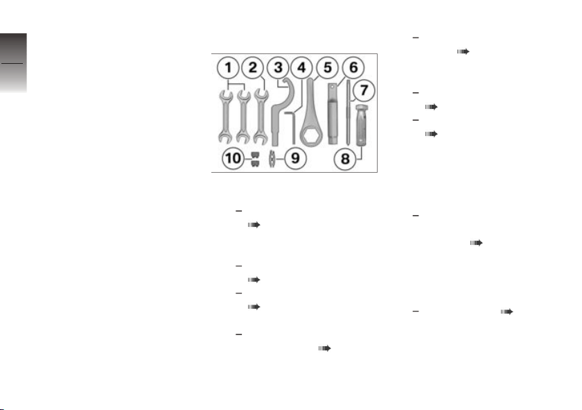
Tool kit
1 Open-ended wrench
Wrench size: 12/13 mm
Adjust chain tension
( 85).
2 Open-ended wrench
Wrench size: 10/16 mm
Adjust mirror arm
( 42).
Removing battery
( 93).
3 Hook wrench
Adjusting spring preload
at rear wheel ( 43).
4 Allen screw
5 mm
4 Headlight range adjust-
ment ( 43).
5 Box wrench
Wrench size: 27 mm
Removing rear wheel
( 81).
Adjust chain tension
( 85).
6 Extension for hook wrench
and ring wrench
7 Reversible screwdriver in-
sert
with cross heads
Replacing front and
rear turn indicator light
sources ( 89).
8 Screwdriver handle
9 Gripping clamp
Gripping clamp is affixed to
the battery carrier.
Replace fuses ( 95).
10 Fuses
10 A, 15 A and 30 A
Page 67
10 Reserve fuses are stuck
in the fuse box and hang
on the cable for the data
link connector.
Front wheel stand
Mount front wheel stand
ATTENTION
Use of the BMW Motorrad
front wheel stand without an
additional center or auxiliary
stand
Component damage cause by
tipping over
Place the motorcycle on the
center stand or an auxiliary
stand before lifting it with the
BMW Motorrad front wheel
stand.
with center stand
Place motorcycle on center
stand, ensuring that it is rest-
OA
ing on a firm and level support
surface.
without center stand
Place motorcycle on an auxil-
iary stand; BMW Motorrad recommends the BMW Motorrad
auxiliary stand.
Mounting rear-wheel stands
( 66).
Use basic stand with front
wheel mount.
The base stand and its accessories are available through
your authorized BMW Motorrad
retailer.
OA
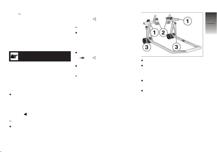
Loosen clamping screws 1.
Push two mounts 2 outward,
continuing until front
suspension fits between them.
Use locating pins 3 to set front
wheel stand to desired height.
Center front wheel stand relative to front wheel and push it
against front axle.
8
65
z
Maintenance
Page 68
8
66
Rear-wheel stand
Mounting rear-wheel
stands
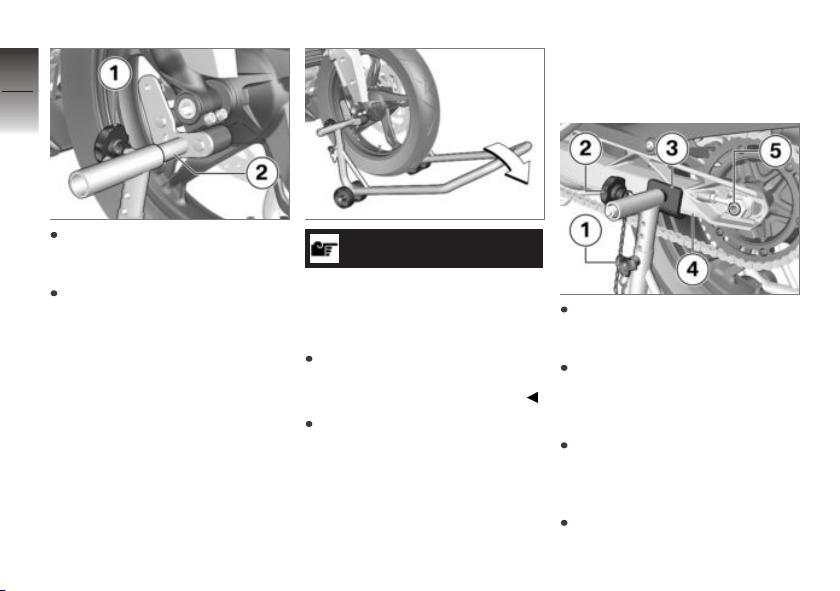
Align two mounts 2 so that
front suspension rests securely
on them.
Tighten the clamping bolts 1.
z
Maintenance
ATTENTION
Center stand retracts if motorcycle is lifted too high.
Component damage cause by
tipping over
When raising the motorcycle, make sure that the center
stand remains on the ground.
Apply uniform pressure to push
front wheel stand down and
raise motorcycle.
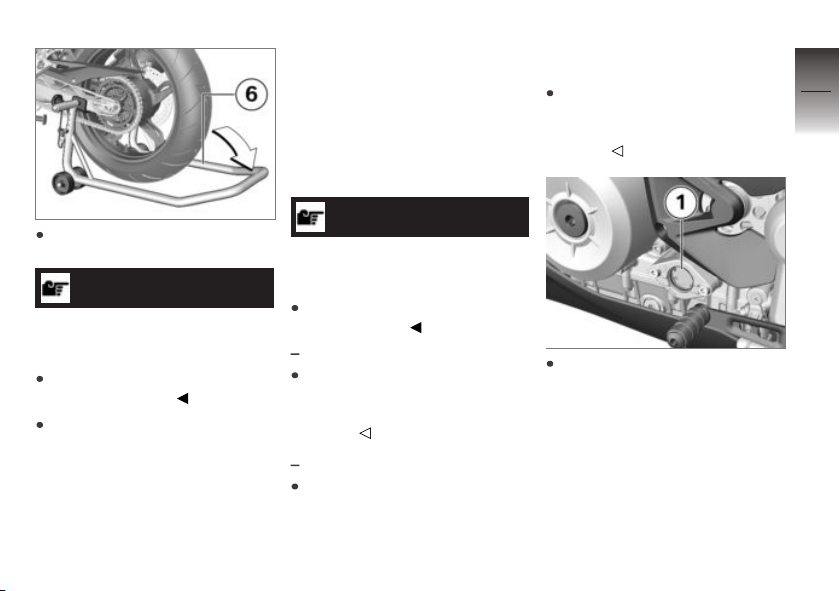
Set the height of the stand 3
so that it raises the rear wheel
slightly off the ground.
Ensure that the stand height is
the same on the left and right,
and secure the mount 3 on
either side with the bolts 1.
Set the mounts 3 to the width
of the rear wheel swinging
arm 4 and secure using clamping bolts 2.
Ensure you do not cover the
axle 5.
Page 69
Engine oil
Checking the engine oil
level
Requirement
The engine is at operating temperature.
ommends the BMW Motorrad
auxiliary stand.
Alternatively: hold the motorcycle upright, preferably with
the assistance of a second
person.
8
67
Position the rear-wheel
stand 6.
ATTENTION
Motorcycle tips to side
Component damage cause by
tipping over
Secure motorcycle against tipping away to side.
Push the rear-wheel stand
down until the motorcycle is
standing upright and the handle of the rear-wheel stand is
resting on the floor.
ATTENTION
Use of too little or too much
engine oil
Engine damage
Always make sure that the oil
level is correct.
with center stand
Place motorcycle on center
stand, ensuring that it is resting on a firm and level support
surface.
without center stand
Place motorcycle on an auxil-
iary stand; BMW Motorrad rec-
OA
OA
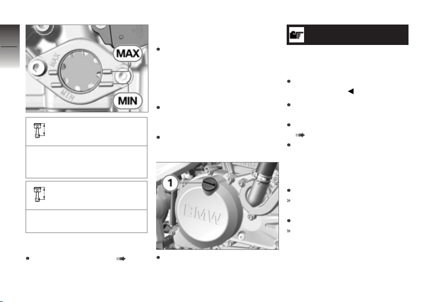
Read oil level on the display 1.
z
Maintenance
Page 70
8
68
Specified level of engine
oil
Between the MIN and MAX
z
Maintenance
marks (Engine at operating
temperature, vehicle is vertical)
Engine oil, quantity for
topping up
max 185 ml (Difference between MIN and MAX)
If oil level is below the minimum
mark MIN:
Topping up engine oil ( 68).
If oil level is above the maximum
mark MAX:
Have oil level corrected at
an authorized service facility,
preferably an authorized
BMW Motorrad retailer.
Topping up engine oil
Park motorcycle, ensuring that
support surface is firm and
level.
Wipe area around oil fill location to clean it.
Remove cap 1 of oil fill location.
ATTENTION
Use of too little or too much
engine oil
Engine damage
Always make sure that the oil
level is correct.
Add engine oil up to specified
level.
Checking the engine oil level
( 67).
Install cap of oil fill location 1.
Brake system
Check brake operation
Operate the brake lever.
There is a clearly perceptible
pressure point.
Actuate the footbrake lever.
There is a clearly perceptible
pressure point.
Page 71
If no clear pressure points are
perceptible:
ATTENTION
Improper working on the
brake system
Endangering of the operating
safety of the brake system
Have all work on the brake system carried out by experts.
Have the brakes checked at an
authorized workshop, preferably
an authorized BMW Motorrad
retailer.
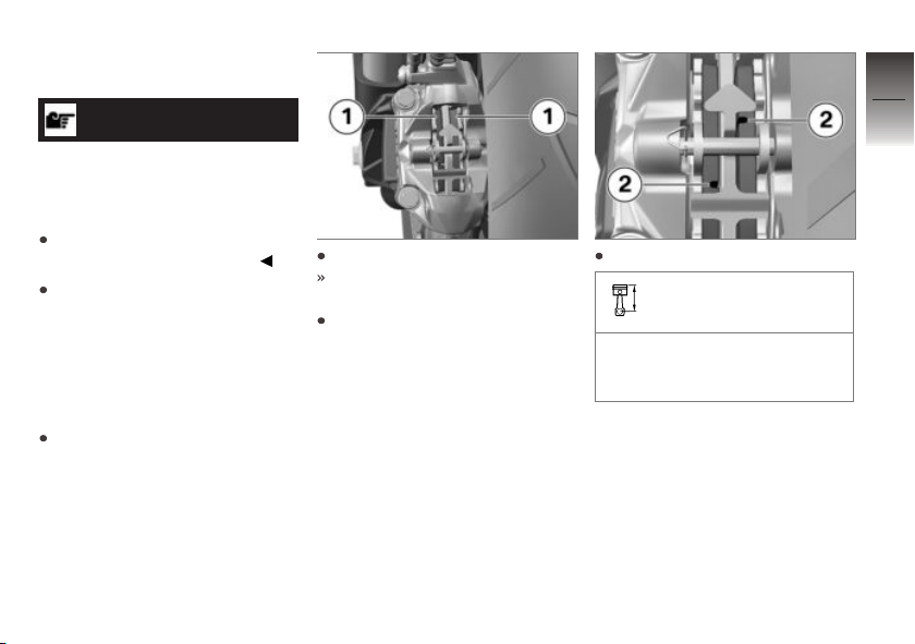
Check front brake pad
thickness
Park motorcycle, ensuring that
support surface is firm and
level.
Turn handlebars to the right.
The brake pads 1 can be seen
from the rear.
Conduct a visual inspection of
the brake pad thickness.
Check the wear indicators 2.
Front brake-pad wear
limit
min 0.04 in (min 1.0 mm)
(Friction lining without carrier
plate)
If the wear indicating marks are
no longer visible:
8
69
z
Maintenance
Page 72
8
70
z
Maintenance
WARNING
Dropping below the minimum
pad thickness
Reduced braking action, damage
to the brake
In order to ensure the operating reliability of the brake system, make sure that the brake
pads are not worn beyond their
minimum thickness.
Have brake pads replaced at
an authorized service facility, preferably an authorized
BMW Motorrad retailer.
BMW Motorrad recommends
you only install genuine brake
pads from BMW Motorrad.
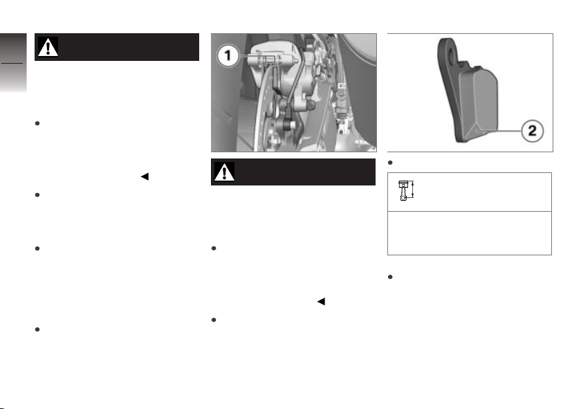
Check rear brake pad
thickness
Park motorcycle, ensuring that
support surface is firm and
level.
WARNING
Dropping below the minimum
pad thickness
Reduced braking action, damage
to the brake
In order to ensure the operating reliability of the brake system, make sure that the brake
pads are not worn beyond their
minimum thickness.
Conduct a visual inspection of
the brake pad thickness. Direction of view: From rear looking
at brake pads 1.
Inspect the chamfer 2.
Rear brake-pad wear
limit
min 0.04 in (min 1.0 mm)
(Friction material without carrier plate)
If the chamfer is no longer visible:
Have brake pads replaced at
an authorized service facility, preferably an authorized
BMW Motorrad retailer.
Page 73
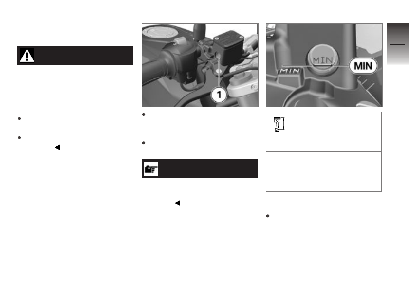
Checking front brake fluid
level
WARNING
Insufficient brake fluid in the
brake-fluid reservoir
Considerably reduced braking
performance caused by air in the
brake system
Adjust the riding mode immediately until the fault is rectified.
Check brake fluid level
regularly.
Set the handlebars so that the
brake fluid reservoir is horizontal.
Check the brake fluid level in
the sight glass 1.
NOTICE
The brake fluid level in the brakefluid reservoir drops due to brake
pad wear.
Front brake fluid level
Brake fluid, DOT4
You should never allow the
brake fluid level to drop below
the MIN mark. (Brake-fluid
reservoir horizontal)
If brake fluid level falls below the
approved level:
Have defect corrected as soon
as possible by an authorized
workshop, preferably an authorized BMW Motorrad retailer.
8
71
z
Maintenance
Page 74
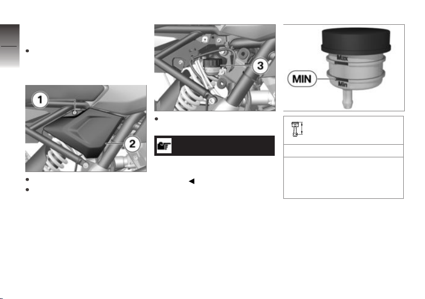
Checking rear brake fluid
8
level
Make sure ground is level and
72
firm and hold motorcycle vertically.
z
Maintenance
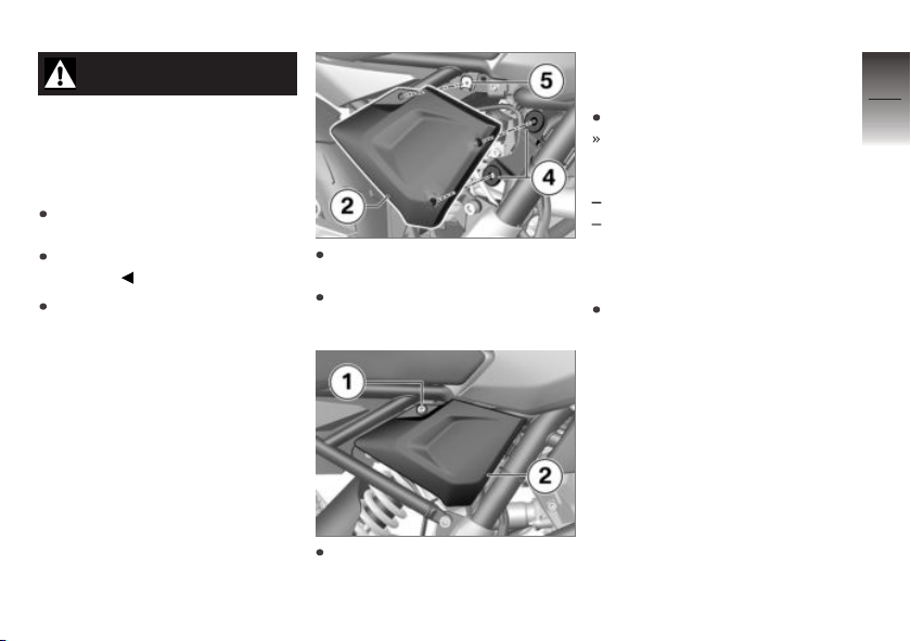
Remove the screw 1.
Pull frame cover 2 out of the
grommets and take off.
Check brake fluid level in brake
fluid reservoir 3.
NOTICE
The brake fluid level in the brakefluid reservoir drops due to brake
pad wear.
Rear brake fluid level
Brake fluid, DOT4
You should never allow the
brake fluid level to drop below
the MIN mark. (Brake-fluid
reservoir horizontal)
If brake fluid level falls below the
approved level:
Page 75
WARNING
Insufficient brake fluid in the
brake-fluid reservoir
Considerably reduced braking
performance caused by air in the
brake system
Adjust the riding mode immediately until the fault is rectified.
Check brake fluid level
regularly.
Have defect corrected as soon
as possible by an authorized
workshop, preferably an authorized BMW Motorrad retailer.
Insert frame cover 2 into grommets 4.
Align frame cover 2 with pushin nut 5.
Fit the screw 1.
Clutch
Check clutch function
Pull back the clutch lever.
The clutch must fully disengage. Signs that the clutch is
fully disengaged:
Easy to change gear
Easy to switch to idling
If this is not the case, or there is
a lack of power transmission after
the clutch has engaged:
Have the clutch checked by an
authorized workshop, preferably
an authorized BMW Motorrad
retailer.
8
73
z
Maintenance
Page 76
Checking clutch lever play
8
74
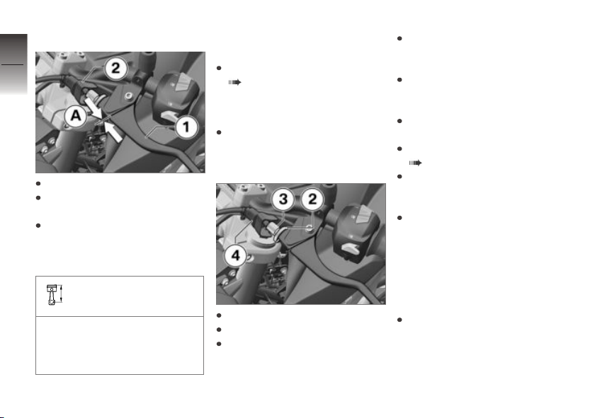
Loosen the cover 2.
Operate clutch lever 1 until
resistance is felt.
z
Maintenance
In this position, measure the
clutch lever play A between
the clutch lever fitting and the
clutch lever.
Clutch lever play
0.04...0.08 in (1...2 mm) (on
the handlebar fitting, handlebars in straight-ahead position,
with cold engine)
If clutch lever play is outside tolerance:
Adjusting clutch lever play
( 74).
If clutch lever play is within tolerance:
Install cover 2.
Adjusting clutch lever
play
Loosen the cover 4.
Loosen the knurled nut 2.
Lift the clutch cable to relieve
the adjusting sleeve 3.
To increase clutch lever play:
screw the adjusting sleeve 3
into the handlebar lever.
To reduce clutch lever play:
unscrew the adjusting sleeve 3
away from the handlebar lever.
Lock the adjusting sleeve 3
using the knurled nut 2.
Checking clutch lever play
( 74).
Repeat the steps until the
clutch lever play is set
correctly.
Install cover 4.
Coolant
Checking coolant level
Requirement
The engine is cold.
Hold the motorcycle upright,
preferably with the assistance
of a second person.
Page 77
Top up coolant
8
75
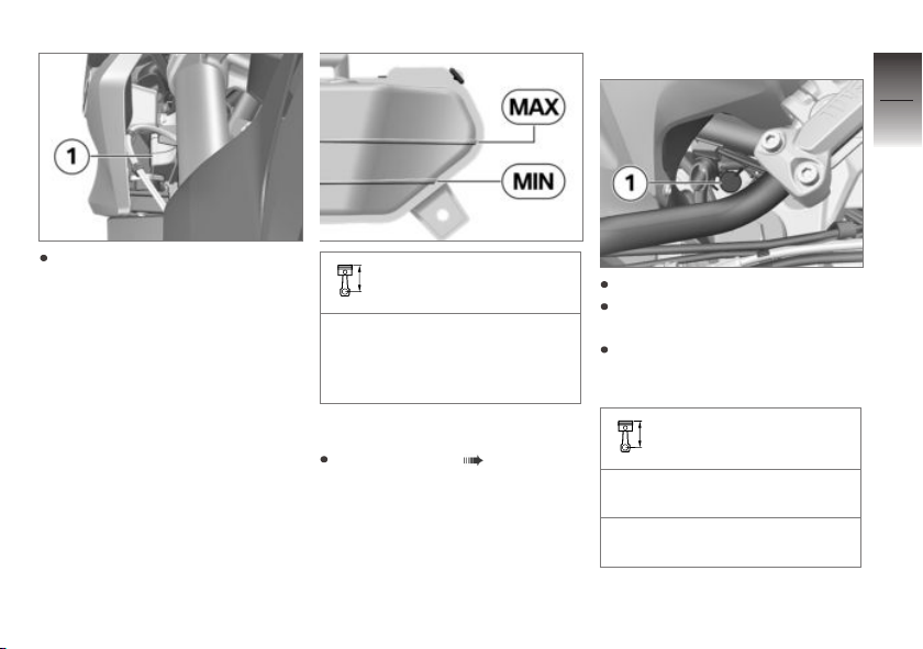
Read off coolant level on the
coolant expansion tank 1. Direction of view: from front
looking at inside of right-hand
side panel.
Coolant, specified level
between MIN and MAX
marks on the expansion tank
(Engine is cold, motorcycle is
upright.)
If coolant level drops below approved level:
Top up coolant ( 75).
Turn handlebars to left.
Open cap 1 of the coolant ex-
pansion tank.
Add coolant up to specified
level. To do this, use a funnel
with a filler neck or hose.
Coolant top-up quantity
Antifreeze and anti-corrosion
agents
150 ml (Difference between
the MIN and MAX markings)
z
Maintenance
Page 78
Checking coolant level ( 74).
When the set level for coolant is
8
reached:
76
Close the cap of the coolant
expansion tank.
Rims and tires
Checking wheel rims
Park motorcycle, ensuring that
support surface is firm and
level.
Subject wheel rims to visual
inspection for defects.
z
Maintenance
Have damaged rims checked
and, if necessary, replaced
by a specialist service facility, preferably an authorized
BMW Motorrad retailer.
Check tire tread depth
WARNING
Riding with heavily worn
tyres
Risk of accident due to poorer
rideability
If necessary, replace the tyres
before the legally specified
minimum tread depth is
reached.
Park motorcycle, ensuring that
support surface is firm and
level.
Measure tire tread depth in
main tread grooves with wear
indicators.
NOTICE
Tread wear marks are integrated
into the main grooves on every
tire. If the tire tread has worn
down to the level of the marks,
the tire is completely worn. The
locations of the marks are indicated on the edge of the tire, e.g.
by the letters TI, TWI or by an
arrow.
When the minimum tread depth
is reached:
Replace the worn tires.
Checking tyre pressure
WARNING
Incorrect tire inflation pres-
sure
Poorer handling characteristic
of motorcycle, reduction of tire
service life
Ensure proper tire inflation
pressure.
WARNING
Valve inserts open of their
own accord at high speeds
Sudden loss of tire inflation pres-
sure
Use valve caps with rubber
sealing ring and screw on
firmly.
Page 79
Park motorcycle, ensuring that
support surface is firm and
level.
Check tyre pressures against
data below.
Tire pressure, front
24.7 psi (1.7 bar) (with cold
tires, one-up and two-up riding)
Tire pressure, rear
27.6 psi (1.9 bar) (with cold
tires, one-up and two-up riding)
If tyre pressure is too low:
Correct tyre pressure.
Wheels
Affect of wheel sizes
on suspension control
systems
The wheel sizes are very important for the ABS. The diameter
and width of the wheels stored
in the control unit have particular significance as the basis for
all necessary calculations. Any
change to these sizes, caused for
example by a switch to wheels
other than the standard installed
ones, can seriously affect handling.
The sensor rings are essential
for correct wheel speed detection; they too must match the
motorcycle's control systems and
consequently cannot be replaced.
If you want to equip your
motorcycle with different wheels,
please contact a specialist
service facility, preferably a
BMW Motorrad retailer.
Removing front wheel
with center stand
Place motorcycle on center
stand, ensuring that it is rest-
ing on a firm and level support
surface.
without center stand
Place the motorcycle on an
auxiliary stand. BMW Motorrad
recommends you use the
BMW Motorrad rear-wheel
stand.
Mounting rear-wheel stands
( 66).
Raise front of motorcy-
cle, preferably using a
BMW Motorrad front wheel
stand, continuing until the
wheel rotates freely.
Mount front wheel stand
( 65).
Mask off the parts of the wheel
rim that could be scratched
OA
OA
8
77
z
Maintenance
Page 80
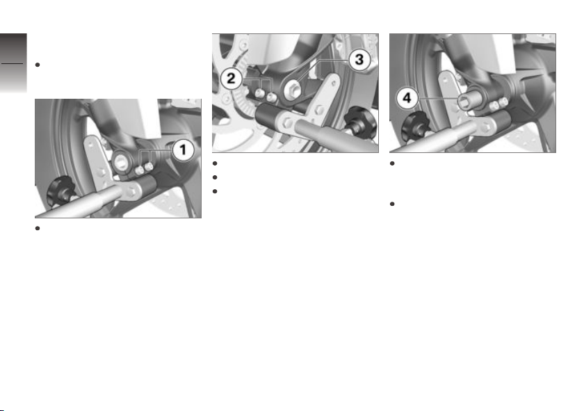
when removing the brake
caliper.
8
Push apart the brake pads a
78
little.
z
Maintenance
Loosen clamping screws 1.
Remove screw 3.
Loosen clamping screws 2.
Slightly press the quick-release
axle inward for a better grip on
the right side.
Pull quick-release axle 4 out
while supporting the front
wheel.
Place front wheel down and
roll it forward out of the front
suspension. Ensure you do
not damage the wheel speed
sensor in the process.
Page 81
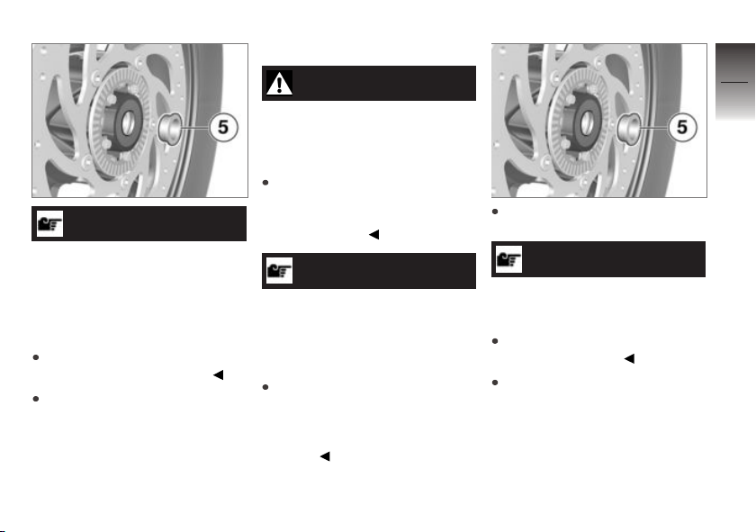
ATTENTION
Unintentional pressing together of brake pads
Component damage when
mounting the brake caliper or
when pressing the brake pads
apart
Do not actuate the brakes with
the brake caliper removed.
Remove spacer bushing 5 from
the wheel hub.
Install front wheel
WARNING
Use of a wheel which does
not comply with series specifications
Malfunctions in ABS operation
Please see the information on
the effect of wheel sizes on the
ABS system at the beginning
of this chapter.
ATTENTION
Tightening of screwed connections with incorrect tightening torque
Damage or loosening of screwed
connections
Always have the tightening
torques checked by a specialized workshop, preferably
an authorized BMW Motorrad
retailer.
Mount spacing bushing 5 on
left side in wheel hub.
ATTENTION
Front wheel installation opposite the running direction
Accident hazard
Observe running direction ar-
rows on tire or rim.
Roll front wheel into front
suspension. When doing so,
make sure that the wheel
speed sensor is not damaged.
8
79
z
Maintenance
Page 82
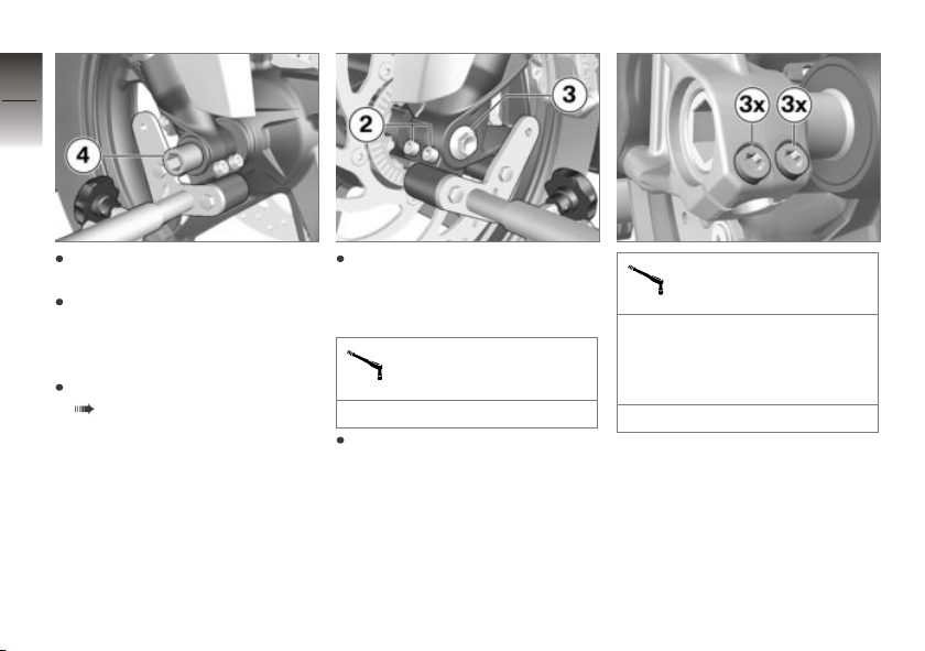
8
80
Lift front wheel and install
quick-release axle 4.
Remove front wheel stand and
firmly compress front forks. Do
z
Maintenance
not operate the brake lever at
the same time.
Mount front wheel stand
( 65).
Install screw 3 with specified
torque. Brace quick-release
axle on the right side at the
same time.
Screw in front wheel
quick-release axle
37 lb/ft (50 Nm)
Tighten clamping bolts 2 to
appropriate torque.
Clamping screw in axle
adapter
Tightening sequence: Tighten
the screws 6 times, alternating
between one and the other
each time
14 lb/ft (19 Nm)
Page 83
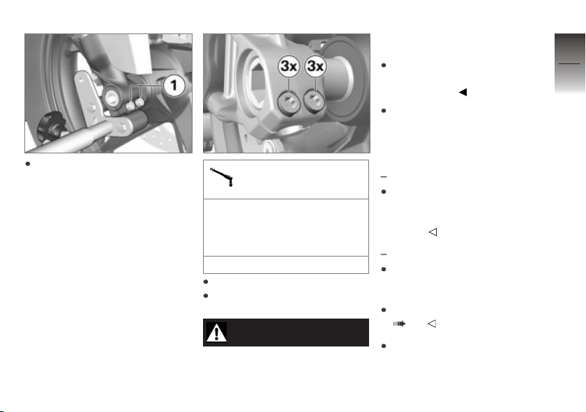
Tighten clamping bolts 1 to
appropriate torque.
Clamping screw in axle
adapter
Tightening sequence: Tighten
the screws 6 times, alternating
between one and the other
each time
14 lb/ft (19 Nm)
Remove front wheel stand.
Remove adhesive tape from
the wheel rim.
WARNING
Brake pads do not contact
the brake disc
Risk of accident due to delayed
braking effect.
Before driving off, check that
the braking effect kicks in with-
out any delay.
Engage the brakes repeatedly,
continuing until the brake pads
seat against the rotors.
Removing rear wheel
with center stand
Place motorcycle on center
stand, ensuring that it is rest-
ing on a firm and level support
surface.
without center stand
Raise motorcycle, preferably
with a BMW Motorrad rear-
wheel stand.
Mounting rear-wheel stands
( 66).
Support the rear wheel, e.g.,
with a wooden block, so that
OA
OA
8
81
z
Maintenance
Page 84
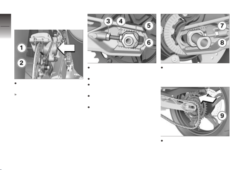
it cannot fall down after the
quick-release axle is removed.
8
82
Press brake caliper 1 against
brake disk 2.
z
Maintenance
Brake piston has been pushed
back.
Remove nut 6 using the right
tool from the toolkit.
Remove washer.
Loosen lock nuts 3 on left and
right.
Screw in the adjusting bolts 4
on the left and right.
Remove the chain tensioner 5
and push the quick-release axle
to the right as far as it will go.
Remove the quick-release
axle 8 and remove the chain
tensioner 7.
Roll rear wheel as far forward
as possible and remove
chain 9 from chain sprocket.
Page 85
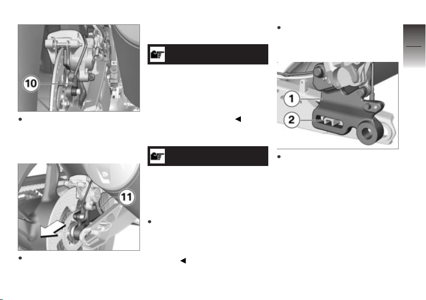
Make sure that the wheel
speed sensor 10 is not
damaged when rolling out the
rear wheel.
Roll rear wheel toward rear
out of swing arm while pulling
brake caliper carrier 11 toward
rear until rear-wheel rim can be
guided past it.
NOTICE
The chain sprocket and the
spacer sleeves on the left and
right are loosely inserted in the
wheel. Exercise care during the
removal, in order that the parts
are not damaged or lost.
Install rear wheel
ATTENTION
Tightening of screwed connections with incorrect tightening torque
Damage or loosening of screwed
connections
Always have the tightening
torques checked by a specialized workshop, preferably
an authorized BMW Motorrad
retailer.
Roll rear wheel on support into
swing arm until brake-caliper
support can be installed.
Place brake-caliper support 1
on the guide 2.
8
83
z
Maintenance
Page 86
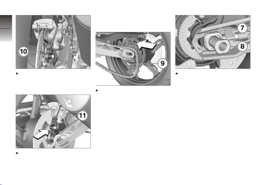
8
84
pushing brake caliper carrier 11
toward the front.
Make sure that wheel speed
sensor 10 is not damaged
when rolling in rear wheel.
z
Maintenance
Roll rear wheel further into
swing arm while simultaneously
Roll rear wheel as far forward
as possible and lay chain 9 on
sprocket.
Insert quick-release axle 8 and
chain tensioner 7 in the swinging arm; insert brake-caliper
support and rear wheel, making
sure that the quick-release axle
interlocks into chain tensioner.
Page 87
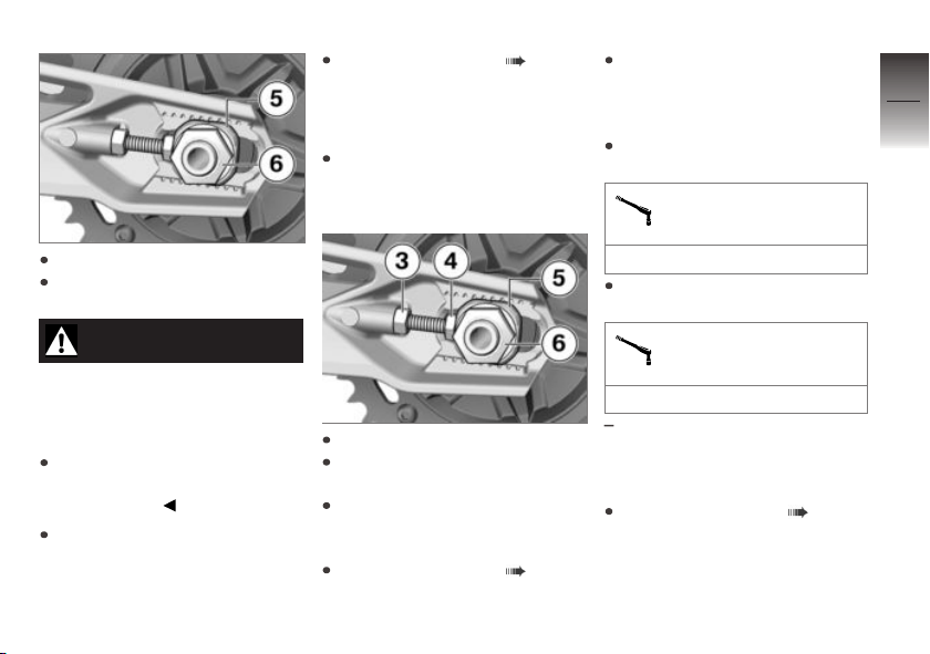
Adjust chain tension ( 85).
Chain
Adjust chain tension
Park motorcycle, ensuring that
support surface is firm and
level.
Ensure that the notch in the
chain tensioner 5 is adjusted
to the same scale value on the
right and left.
Tighten locknuts 3 on left and
right to the specified torque.
Locknut of drive-chain
tensioning screw
8
85
Insert chain tensioner, left 5.
Install nut 6 with washer, however do not tighten yet.
WARNING
Brake pads do not contact
the brake disc
Risk of accident due to delayed
braking effect.
Before driving off, check that
the braking effect kicks in without any delay.
Engage the brakes repeatedly,
continuing until the brake pads
seat against the rotors.
Loosen the nut 6.
Loosen lock nuts 3 on left and
right.
Adjust chain tension with adjusting screws 4 on left and
right.
Check chain tension ( 86).
14 lb/ft (19 Nm)
Tighten nut 6 to the specified
torque.
Rear-wheel quick-release
axle in swinging arm
74 lb/ft (100 Nm)
Once you have tightened the
rear wheel quick-release axle,
complete the following task
again:
Check chain tension ( 86).
z
Maintenance
Page 88
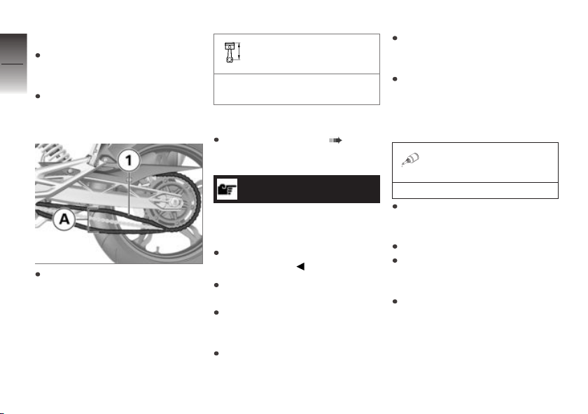
Check chain tension
8
Park motorcycle, ensuring that
support surface is firm and
86
level.
Turn the rear wheel until the
position with the lowest chain
sag is reached.
Chain sag
1.6...2 in (40...50 mm) (Motorcycle unloaded on side stand)
If the chain tension is outside the
approved tolerance:
Adjust chain tension ( 85).
Lubricate chain
Clean drive chain with suitable
cleaning agent, dry and apply
chain lubricant.
To extend and maximize
the chain's service life
BMW Motorrad recommends
using BMW Motorrad chain
lubricant or:
Lubricant
z
Maintenance
Using a screwdriver, push
chain 1 up and down in the
middle between the chain takeup roller and chain sprocket
and measure the chain
tension A.
ATTENTION
Insufficient cleaning and lubrication of the drive chain
Increased wear
Clean and lubricate the drive
chain regularly.
Lubricate the drive chain every
third fuel stop.
After driving though water or
dust and dirt perform the lubrication at shorter intervals.
Switch off ignition and engage
Neutral.
Chain spray
Wipe off excess lubricant.
Check chain wear
Engage 1st gear.
Rotate rear wheel toward front
of motorcycle until the chain is
tensioned.
Determine chain length below
rear wheel swinging arm.
Page 89
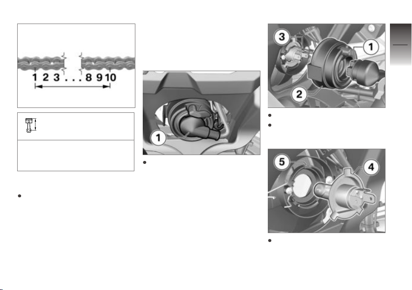
Light sources
Replacing light sources
for low-beam and highbeam headlight
8
87
Permissible chain length
max 5.7 in (max 144.30 mm)
(measured over the center of
10 rivets, chain under tension)
If the chain has reached the maximum approved length:
Contact an authorized service
facility, preferably an authorized
BMW Motorrad retailer.
Loosen connector 1.
Remove cover 2.
Loosen wire spring 3 from the
locking and open.
Pull light source 4 out of
socket 5.
z
Maintenance
Page 90
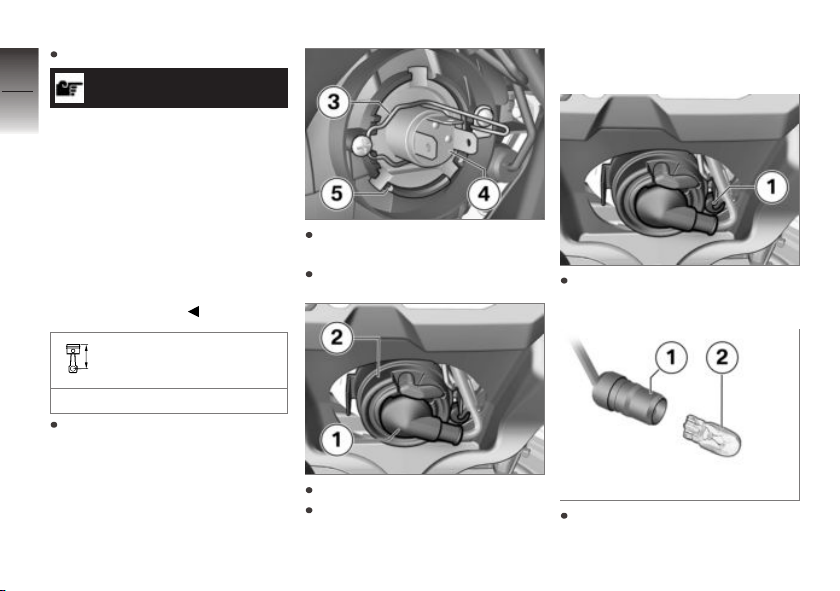
Replace defective light source.
8
88
z
Maintenance
NOTICE
Light sources featuring specification ratings for higher levels of illumination are commercially available as special accessories. These light sources have
a shorter service life than conventional light sources and also
generate more heat. Under some
circumstances the high levels of
heat radiation can damage the
headlight assembly.
Bulb for low-beam and
high-beam headlight
H4 / 12 V / 60 W / 55 W
To protect the glass against
soiling, grasp the light source 4
by the base only.
Align the light source 4 and
press into the socket 5.
Install wire spring 3.
Install cover 2.
Attach plug 1.
Replacing parking light
light source
Pull the socket 1 out of the
headlight housing.
Pull light source 2 out of
socket 1.
Page 91
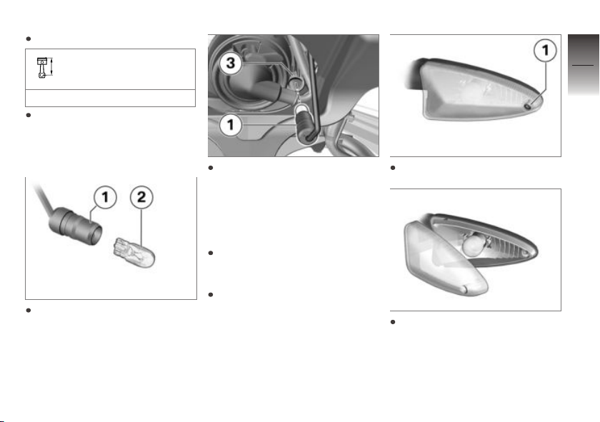
Replace defective light source.
Bulb for parking light
W5W / 12 V / 5 W
To prevent contaminants from
being deposited on the glass
surface, always use a clean, dry
cloth to hold the light source.
Insert light source 2 into
socket 1.
Insert socket 1 into the headlight housing 3.
Replacing front and
rear turn indicator light
sources
Park motorcycle, ensuring that
support surface is firm and
level.
Turn off ignition.
Remove the screw 1.
Remove the lens from the
housing by pulling it outward
on the side with the screw.
8
89
z
Maintenance
Page 92
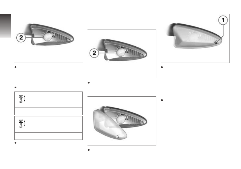
8
90
always use a clean, dry cloth to
hold the light source.
Remove bulb 2 from
light housing by turning it
counterclockwise.
Replace defective light source.
z
Maintenance
Bulbs for flashing turn
indicators, front
RY10W / 12 V / 10 W
Bulbs for flashing turn
indicators, rear
RY10W / 12 V / 10 W
To prevent dirt from being deposited on the glass surface,
Install light source 2 by turning
clockwise in light housing.
Insert inside end of lens into
light housing and close it.
Fit the screw 1.
Replacing LED tail light
If the LEDs in the tail lamp fail,
the tail lamp must be replaced.
In this case:
Contact an authorized service
facility, preferably an authorized
BMW Motorrad retailer.
Replace license plate light
If the LEDs for the license plate
lamp in the tail lamp fail, the tail
lamp must be replaced. In this
case:
Page 93

Contact an authorized service
facility, preferably an authorized
BMW Motorrad retailer.
Jump-starting
CAUTION
Touching live parts of the ignition system when the engine is running
Electrocution
Do not touch parts of the ignition system when the engine is
running.
ATTENTION
Current too high when jumpstarting the motorcycle
Cable fire or damage to the motorcycle electronics
Do not jump-start the motorcycle using the power socket,
only via the battery terminal.
ATTENTION
Contact between crocodile
clips of jump leads and motorcycle
Danger of short circuit
Use jump leads fitted with fully
insulated crocodile clips at both
ends.
ATTENTION
Jump-starting with a voltage
higher than 12 V
Damage to the motorcycle's
electronics
The battery of the donor vehicle must not exceed a voltage
of 12 V.
Do not disconnect battery from
onboard electrical system for
jump-starting procedure.
Removing seat ( 39).
Allow engine on support mo-
torcycle to run while jump-
starting.
Begin by clamping one end of
the red jumper cable to the
positive terminal of the dis-
charged battery and clamping
the other end to the positive
terminal of the donor battery.
Then connect one end of the
black jump cables to the nega-
tive terminal of the donor bat-
tery, and the other end to the
negative terminal of the dis-
charged battery.
Start engine of motorcycle with
discharged battery in usual
way; if engine does not start,
wait a few minutes before re-
peating attempt in order to pro-
tect starter motor and donor
battery.
Allow both engines to idle for a
few minutes before disconnect-
ing the jump cables.
8
91
z
Maintenance
Page 94

Disconnect the jump cable
from the negative terminal first,
8
then disconnect the second
92
cable from the positive terminal.
Install seat ( 40).
Battery
Maintenance instructions
Correct battery maintenance
combined with proper charging
and storage procedures extends
the battery's service life, and is
z
Maintenance
also required for warranty claims.
Compliance with the points below is important in order to maximize battery life:
Keep the surface of the battery
clean and dry.
Do not open the battery.
Do not top up with water.
Be sure to read and comply
with the instructions for charging the battery on the following
pages.
Do not turn the battery upside
down.
ATTENTION
Discharging of the connected
battery by the vehicle electronics (e.g. clock)
Total discharge of battery leading
to a rejection of warranty claims
During riding breaks of more
than 4 weeks, connect a
trickle-charger to the battery.
Charging a connected
battery
ATTENTION
Charging the battery connected to the vehicle using
the battery terminals
Damage to the motorcycle's
electronics
Disconnect the battery before charging on the battery
terminals.
Disconnect battery from motorcycle ( 93).
Charging a disconnected
battery
Disconnect battery from motorcycle ( 93).
Charge battery using a suitable
charger.
Comply with operating instructions of charger.
Once battery is fully charged,
disconnect charger's terminal
clips from battery terminals.
NOTICE
In the case of longer periods
when the motorcycle is not be-
ing used, the battery must be
recharged regularly. See the
instructions for caring for your
battery. Always fully recharge
Page 95

the battery before returning it to
use.
Connect battery to vehicle
( 93).
Disconnect battery from
motorcycle
Park motorcycle, ensuring that
support surface is firm and
level.
Removing seat ( 39).
ATTENTION
Incorrect battery disconnection
Danger of short circuit
Follow the disconnection
sequence.
Disconnect the battery earth
lead 1 first.
Then push the protective
cap 3 to the side and
disconnect the positive battery
cable 2.
Connect battery to vehicle
First install the positive battery
cable 2 and cover with the protective cap 3.
Then install negative battery
cable 1.
Install seat ( 40).
Removing battery
Removing seat ( 39).
Disconnect battery from motor-
cycle ( 93).
Remove the screw 1.
8
93
z
Maintenance
Page 96
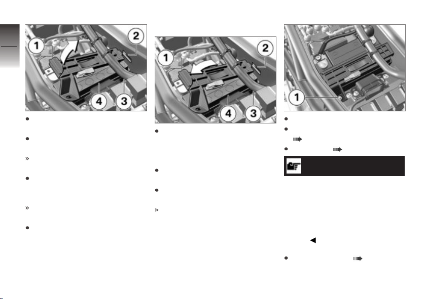
8
94
Install battery
Unhook and lift up the holder 1
on the left.
Unloosen the holder from the
battery tray 2 on the right.
z
Maintenance
The holder is now only attached to the wiring harness 3.
Push the holder and the wiring
harness to the right out of the
way.
You can now remove the battery.
Lift the battery 4 up and out.
Work it back and forth slightly if
it is difficult to remove.
Place the battery 4 in the battery compartment with the
positive terminal on the right
in the direction of travel.
Attach the right side of the
holder to the battery tray 2.
Fold the holder 1 down and
attach on the left.
The wiring harness 3 is now
back in its initial position.
Fit the screw 1.
Connect battery to vehicle
( 93).
Install seat ( 40).
NOTICE
If the motorcycle was
disconnected from the battery
for a longer time, the current
date must be entered in the
instrument cluster to ensure the
proper operation of the service
display.
Setting the date ( 37).
Page 97
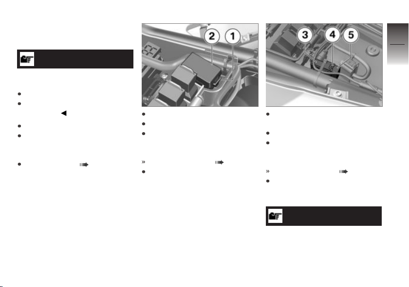
Fuses
Replace fuses
ATTENTION
Bypassing defective fuses
Risk of short circuit and fire
Do not bypass defective fuses.
Replace defective fuses with
new fuses.
Switch off ignition.
Park motorcycle, ensuring that
support surface is firm and
level.
Removing seat ( 39).
Press locking device 1.
Open the fuse box 2.
Replace defective fuse in accordance with following fuse
assignment diagram.
Fuse assignments ( 96)
Close the fuse box 2 again.
Make sure that the lock 1 has
engaged.
Press the lock 4 in on both
sides.
Remove the cap 5.
Replace defective fuse in ac-
cordance with following fuse
assignment diagram.
Fuse assignments ( 96)
Replace the cap 5. Make sure
that the lock 4 on the fuse
box 3 engages.
NOTICE
If the fuses blow frequently, have
the electrical system checked by
an authorized specialized work-
8
95
z
Maintenance
Page 98
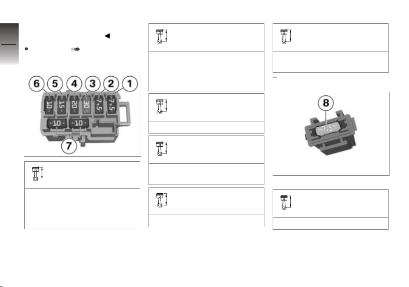
shop, preferably an authorized
BMW Motorrad retailer.
8
Install seat ( 40).
96
Fuse assignments
z
Maintenance
Fuse 2
7.5 A (Heated grips, data link
connector, engine control unit,
additional onboard socket,
ABS pressure modulator)
Fuse 3
30 A (Main fuse)
Fuse 4
Fuse 6
10 A (Instrument cluster, engine control unit)
Spare fuses 7
Fuse 1
7.5 A (Oxygen sensor, evaporative emission valve, secondary air system, injection
system, electric fuel pump)
20 A (ABS pressure modulator)
Fuse 5
15 A (Lighting, horn)
Fuse 8 for radiator fan
Fuse for radiator fan
7.5 A (Radiator fan)
Page 99
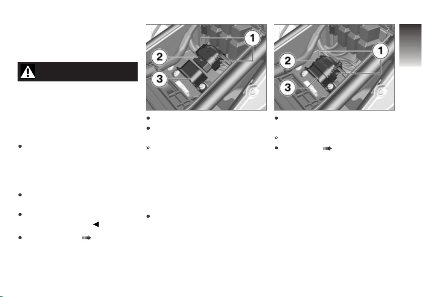
Diagnostic connector
Removing the diagnostic
connector
CAUTION
Incorrect procedure followed
when disconnecting the data
link connector for the OnBoard Diagnostics.
Motorcycle experiences malfunctions
Only have the data link connector disconnected by a specialist workshop or other authorized persons during your next
BMW Service appointment.
Have the work performed by
appropriately trained staff.
Refer to the vehicle manufacturer specifications.
Removing seat ( 39).
Press the locks 1 together.
Remove the diagnostic connector 2 from the bracket 3.
The diagnosis and information
system interface can be connected at the diagnostic connector 2.
Securing data link
connector
Disconnect the diagnosis and
information system interface.
Seat diagnostic connector 2
into the bracket 3.
The locks 1 engage.
Install seat ( 40).
8
97
z
Maintenance
Page 100

8
98
z
Maintenance
 Loading...