

Page 1

Repair manual
C1
C1 200
BMW Motorrad
After Sales
Page 2

Published by BMW Motorrad
After Sales
UX-VS-2
All rights reserved. Reprints, translation and duplication allowed exclusively with prior written permission
from the publisher.
Errors and omissions excepted. We reserve the right to introduce technical modifications at any time.
Printed in Germany 03/01
Page 3
Preface
This Repair Manual is intended to assist you in performing all essential maintenance and repair operations
to a professional standard. In its role as a reference source for service personnel, it supplements and expands upon the theoretical and hands-on instruction provided at our training centres to enhance the quality
of our service.
A new edition of this manual will be issued in response to required revisions or the need to incorporate additional information (supplements).
The illustrations and descriptions contained in this manual apply exclusively to standard, unmodified BMW
Motorcycles and/or BMW Motorcycles equipped with factory-approved BMW accessories and options.
The Repair Manual's structure reflects the logical sequence in which the operations it describes will be
•
performed: removal, dismantling, repairs, assembly and installation.
The individual chapters in this manual correspond to the motorcycle's individual assembly groups.
•
11 10.
Chap. chapter page continued
A reference arrow with chapter and page calls your attention to additional information contained in another
section of the manual.
e.g. a ................ Refer to Assembly Group 46
Group "00" describes the operations carried out in the course of each Inspection. The various inspec-
•
tion routines are numbered I, II, III and IV. To help in maintaining a continuous, logical work sequence,
these same numerical designations are employed to identify the subsequent sections describing the actual repair operations.
Use of the BMW special tools needed for certain operations is described in the work instructions.
•
When the need arises, repair instructions are also issued in the form of Service Information Bulletins. This
information is then incorporated into subsequent editions of the repair manual. We also recommend the
lavishly illustrated Electronic Parts Catalogue as a supplementary source of information.
When individual steps within an overall operation only apply to motorcycles with specific accessories or
optional equipment, the options to which the steps refer are identified by brackets at the start of the line,
such as
Please devote your careful attention to the following pages with their explanations describing the symbols
used in the manual and their significance.
BMW Motorrad
After Sales
[with heated grips]
.
Published by BMW Motorrad
After Sales
UX-VS-2
80788 München
All rights reserved. Reprints, duplication and translation, in whole or part, are allowed exclusively with prior
written permission.
We reserve the right to introduce technical modifications at any time. Errors and omissions excepted.
Printed in Germany
Page 4

How to use this manual
Each chapter starts with a table of contents.
Following the table of contents is a table containing the techical data and specifications for the chapter's
subject.
Chapter 00 describes maintenance procedures and provides general information as well as the pre-delivery
inspection; it furnishes all torque specifications along with listings of fluids and lubricants.
Explanation of symbols
This repair manual for the C1 employs the following symbols; please refer to the table for their meanings.
Special notices for more efficient procedures
L
Note:
These special notices help technicians work more efficiently when operating, inspecting, adjusting and
maintaining motorcycles.
e
Attention:
Special information and precautionary notices to prevent damage to the motorcycle. Failure to observe
these mandatory precautions may invalidate the warranty.
d
Warning:
Precautions intended to protect the rider and/or other individuals against injury as well as potentially fatal
hazards.
Contents
The titles of the operations described in this chapter ............. together with the page numbers
Operations
Operations
•
A dot or period identifies individual procedures described under a title
•
– Previous operations
– The hyphen identifies procedures described in more detail under a different title or in another chapter
Remove means:
to completely unscrew a retaining component (such as a bolt or screw)
or
to detach a component (such as an injection rail) and move it enough to gain access to assemblies installed
behind it (such as a throttle-valve).
Loosen means:
to unscrew an attachment (such as a bolt or screw) without removing it entirely from its threaded socket or
retainer
X
Torque specifications:
These data are indicated whenever torques deviate from the standards defined in DIN EN 24 014 and
DIN 912 ISO.
Page 5
Contents
<< Back
Group / Chapter
00 Tightening torques operating fluids
00 Pre-delivery check
00 Maintenance
11 Engine
12 Engine electrics
13 Fuel preparation and control
16 Fuel tank and lines
17 Radiator
18 Exhaust system
21 Clutch
24 Gearbox
31 Front forks
32 Steering
>> Continuation
Page 6
Group / Chapter
33 Rear wheel drive
34 Brakes
36 Wheels and tyres
46 Frame
51 Equipment
>> Continuation
52 Seat
61 General electrical equipment
62 Instruments
63 Lights
65 Optional extras
72 Seat belts
<< Back
Page 7
BMW Motorrad
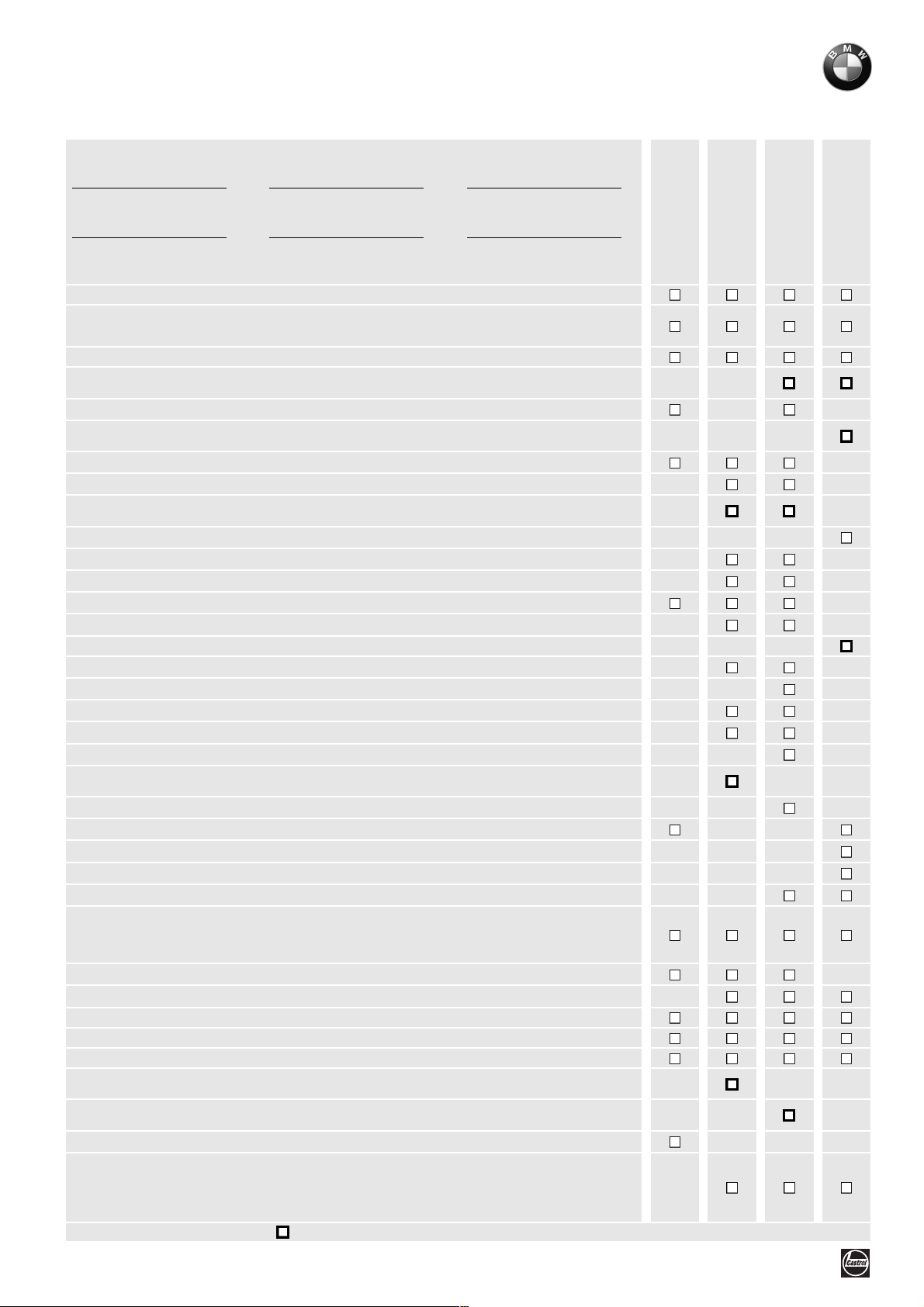
Maintenance schedule
C1, C1 200
Customer Licence No. Mileage
Job Order No. Date Mechanic's signature
MoDiTeC/DIS plus
Change the engine oil while at regular operating temperature and replace the oil filter element
If the vehicle is ridden for short distances only or at outside temperatures below 0° C (32° F): every 3 months or after
every 3,000 km (1,800 miles) at the latest
Clean oil strainer and magnetic plug
Change transmission fluid
every 30,000 km/18,000 miles or 3 years
Inspect coolant level, top up if necessary, inspect hoses for damage, chafing points
Change the coolant
every 2 years
Check valve clearances and adjust if necessary
Replacing spark plug
Replace air filter element
shorten change interval if severely dirty or dusty
Drain condensate drain hose from air manifold
Brake hoses and connections: check condition and routing
Check operation of brake system and check for leaks; repair/replace as necessary
Inspect brake fluid level at front/rear
Examine brake pads and discs for wear, renew if necessary
brake fluid
Renew
Replace variator belt
Check clutch liner, replace if necessary
Cleaning mesh filter of variator
Grease driving variator (greased version)
Check and clean driving variator (ungreased version, replace variator if necessary)
Replace complete driving variator
every 22,500 km/14,000 miles, greased version only
Check wheel bearings for play; replace if necessary
Checking that leading-link mounts are free of play
Battery: check battery acid level, if necessary add distilled water
Clean and grease the battery terminals, if necessary
Check freedom of movement of Bowden cables, check for abrasion and damage
Easy-lift mechanism:
– Check operation of mechanism and check freedom of movement
– Inspect Bowden cables for damage and signs of wear and chafing, ensuring that mechanism moves
freely without binding; check free travel and adjust as required
Check windscreen washer system; adjust nozzles if necessary and top up washer fluid in reservoir
Check windscreen wiper; replace wiper blade if necessary
Safety elements: check cable for release, belt buckles, belt strap, inertia reels, and belt locks
Check crash element for damage
Inspect shoulder bar for damage, replace deformation element if necessary
Replace fuel filter
every 37,50 0 km/22,500 miles
Only ABS: Replace seal in brake master cylinder
every 30,000 km/18,000 miles
Check tightness of bolts and nuts at engine mountings and quick-release axles
Final inspection with road safety and functional check:
– Clutch engagement, steering, front and rear brake
– Condition of tyres and wheels, tyre inflation pressure
– Lights and signalling equipment, telltale and warning lights, instruments
– If necessary, test ride
*) Write up on separate invoice; Not part of standard service procedure
, read fault code memory
*)
at least
*)
*)
once a year
*)
*)
*)
*)
*)
*)
*)
*)
BMW Inspection
at 10,00 km/600 miles
BMW Maintenance
Service every
7,500 km/4,500 miles
BMW Inspection
every 15,000 km/
9,000 miles
BMW
Annual Service
UX-VS-2, 10.2001
BMW recommends Castrol
Page 8
BMW Motorrad
Pre-delivery Check
C1, C1 200
Customer Registration number
Order no. Signature of mechanic
Inspect transportation packaging for damage
C1:
–Unpack
– Inspect for damage
–Attach parts
–Clean
Battery:
–Remove
– Pour in electrolyte
–Charge
–Grease terminals
– Install (mark date of installation)
BMW
Pre-delivery Check
Inspect complete scope of supply:
– Toolkit
– Documentation
–Keys
– Scope of optional equipment
Inspect tyre inflation pressure
Pour in fuel
Operational check as final inspection:
– Engine idling
– Clutch, clutch engagement
–Steering
–Seat belt
– Easy-lift mechanism
– Brakes, front and rear
– Lights and signalling equipment, telltale and warning lights, instruments
–Set headlight
– If necessary, test ride
UX-VS-2, 10.2001
BMW recommends Castrol
Page 9

BMW Motorrad
Service data
C1, C1 200
Item Specified
value
Oil capacities
Engine (with filter)
Gearbox
Coolant
Cooling system
Expansion tank
Windshield washer fluid
Brake fluid
Valve clearances
Measured cold, maximum 35 °C (95 °F)
Spark plugs
Electrode gap 0.8…0.9
Idle speed
Tyre pressures (tyres cold)
Solo
Full load
Tightening torques:
Engine oil drain plug
Oil strainer to engine
Engine water drain plug
Oil filter cover
Camshaft gears to camshaft
Guide rail to camshaft support
Chain tensioner plug
Camshaft bearing bridge
Valve cover
Machine bolt TDC setting
Spark plug
Driving variator
Driving variator cover
Driven variator
Locknut of clutch to driven variator
Variator cover to power train link
Ventilation cover for variator
Front stub axle
Clamping bolts for front stub axle
Brake calliper at fork slider tube
Bleed screw in brake calliper
Cover of handbrake control
Rear stub axle,
Exhaust to cylinder head
Auxiliary link to power train link M8
Auxiliary link to power train link M10
Silencer to auxiliary link
Suspension strut to power train link/brake calliper holder
Link mounting to power train link
Tubular link to frame
Stand to frame
Rubber element to tubular link
Cladding bolts
Order no. 01 71 0 136 450 UX-VS-2, 03.2001 Printed in Germany
use nut only once
1.0 (0.22)
0.090 (0.020)
1.25 (2.2)
0.2 (0.35)
1.0 (1.8) litres (Imp pints)
Inlet: 0.05…0.14
(0.002…0.006)
Exhaust: 0.20…0.29
(0.009…0.010)
(0.031…0.035)
1900 rpm
Front/rear
1.9/2.1 (27.6/30.5)
1.9/2.4 (27.6/34.8)
20
30
10
10
30
10
35
10
10
15
15
60
4
60
50
10
9
30
21
41
14
Hand-tight
130
15
21
60
21
21
73
73
41
42
2.8
Unit of measure or
specification
litres (Imp pints)
15W40
litres (Imp pints)
API GL 4
litres (Imp pints)
litres (Imp pints)
Mixing ratio:
Water: 50%
Antifreeze: 50%
Protection down to
–25 °C (-13 °F)
Water and cleaning prod-
uct, antifreeze as required
DOT 4
mm
(in)
mm
(in)
NGK CR8 EB
mm
(in)
bar (psi)
bar (psi)
Nm
Nm
Nm
Nm
Nm (Loctite 243)
Nm (Loctite 243)
Nm
Nm
Nm
Nm
Nm
Nm (Loctite 243)
Nm
Nm
Nm (Loctite 243)
Nm
Nm
Nm
Nm
Nm
Nm
Nm
Nm
Nm
Nm
Nm (Loctite 243)
Nm
Nm
Nm
Nm
Nm
Nm
Nm
Page 10

Page 11

00
00 Tightening torques
operating fluids
Contents
Torque specifications
11 Engine
...........................................................................................................................................3
12 Engine electrical system
13 Fuel injection system
16 Fuel tank
.......................................................................................................................................4
17 Cooling system
18 Silencer (muffler)
21 Clutch
24 Gearbox
31 Front forks
32 Steering
............................................................................................................................................5
........................................................................................................................................5
...................................................................................................................................6
........................................................................................................................................6
33 Final-drive unit
34 Brakes
36 Wheels
46 Frame
51 Equipment
52 Seats
...........................................................................................................................................7
..........................................................................................................................................8
............................................................................................................................................8
...................................................................................................................................9
............................................................................................................................................ 10
61 Electrical equipment
62 Instruments
63 Lights
........................................................................................................................................... 11
............................................................................................................................... 11
65 Optional extras
72 Seat belts
................................................................................................................................... 11
.................................................................................................................3
..............................................................................................................4
.........................................................................................................................4
.......................................................................................................................5
...........................................................................................................................7
............................................................................................................. 10
........................................................................................................................ 11
Page
.......................................................................................................4
Table of service products
....................................................................................................... 12
00.1
Page 12

00.2
Page 13

00
Torque specifications
Model C1
Connection
11 Engine
Oil drain plug, magnetic Nm 20
Threaded plug, oil strainer Nm 30
Oil filter cover Nm 10
Threaded TDC set plug Nm 15
Alternator
Alternator cover up to engine no.: 745 594 Nm 10
Alternator cover from engine no.: 745 595 Nm 12
Ignition trigger, Tapite screw Nm 6 LOCTITE 243
Holder for alternator cable, Tapite screw Nm 6 LOCTITE 243
Reluctor to crankshaft, locking fluid Nm 30 LOCTITE 243
One-way clutch, locking fluid Nm 30 LOCTITE 243
Alternator to cover Nm 10
Chain tensioning rail, locking fluid Nm 10 LOCTITE 243
Cylinder head
Cylinder head cover Nm 10
Collar nut Nm 30 ±1
Securing screw Nm 10
Spark plug Nm 15
Camshaft sprockets, locking fluid Nm 30 LOCTITE 243
Bearing cap Nm 10
Chain guide, locking fluid Nm 10 LOCTITE 243
Plug for chain tensioner Nm 35
Vent screw Nm 9
Dual temperature sensor, locking fluid Nm 15 LOCTITE 243
Housing
Starter motor Nm 10
Oil pressure switch, locking fluid Nm 12 LOCTITE 243
Oil pressure valve Nm 30
Stud (tie bolt) Nm 10
Housing screws Nm 10
Oil pump, Tapite screw Nm 6 LOCTITE 243
Water-pump housing, Tapite screw Nm 6 LOCTITE 243
Spring strut at bottom Nm 21
00.3
Page 14
Model C1
Connection
12 Engine electrical system
Spark plug Nm 15
Ignition coil to frame Nm 5
Ignition trigger, Tapite screw Nm 6 LOCTITE 243
Reluctor to crankshaft, locking fluid Nm 30 LOCTITE 243
One-way clutch, locking fluid Nm 30 LOCTITE 243
Alternator to cover Nm 10
Starter motor Nm 10
Model C1
Connection
13 Fuel injection system
Fuel filter clamp Nm 5
Holder for injection nozzle (self-tapping) Nm 4 LOCTITE 243
Pressure regulator clamp Nm 9
BMS control unit Nm 5
Intake manifold Nm 9
Air plenum clamp Nm Hand-tight
Air filter housing (inner/outer) Nm 9
Throttle cable Nm 8
Spring strut at bottom Nm 21
Model C1
Connection
16 Fuel tank
Fuel filter clamp Nm 5
Bracket, fuel tank to frame Nm 9
Union nut (fuel-pump unit) Nm 20
Baseplate to frame
Bracket for washer fluid reservoir on frame
Bracket for washer fluid reservoir/ABS control unit on frame
Model C1
Connection
Nm 9
Nm 9
17 Cooling system
Drain plug Nm 10
Vent screw Nm 9
Bracket for seat latch, right, to frame Nm 42
Bracket for seat latch, left, to frame Nm 5
00.4
Page 15
Model C1
Connection
17 Cooling system
Expansion tank to frame upright Nm 3
Front frame to cross brace Nm 14
Air duct to fan shroud Nm 9
Radiator to front frame Nm 9
Fan shroud to radiator Nm 9
Air duct to front frame Nm 9
Filler bowl to front frame Nm 9
Coolant pipe clamp to frame Nm 9
Screw clamp on engine Nm Hand-tight
Bleeder screw to engine Nm 9
Model C1
Connection
18 Silencer (muffler)
Shield to holder Nm 5
Exhaust pipe to cylinder head Nm 15
Silencer to auxiliary swing arm Nm 21
Oxygen sensor to silencer Nm 23
Model C1
Connection
21 Clutch
Vent cover for variator Nm 9
Variator cover Nm 10
Driven variator (clutch drum) Nm 60
Locknut on driven variator, locking fluid Nm 50 LOCTITE 243
Model C1
Connection
24 Gearbox
Variator
Vent cover for variator Nm 9
Variator cover Nm 10
Drive variator, locking fluid Nm 60 LOCTITE 243
Cover, drive variator Nm 4
Driven variator (clutch drum) Nm 60
Locknut of driven variator, locking fluid Nm 50 LOCTITE 243
00.5
Page 16
Model C1
Connection
24 Gearbox
Gearbox
Gearbox cover Nm 11
Gearbox drain plug Nm 20
Gearbox filler plug Nm 5
Model C1
Connection
31 Front forks
Fork cross brace to frame (screw stud) locking fluid
Leading link to telescopic tube cross brace
locking fluid
Brake line bracket on fork cross brace Nm 5
Fork stanchion to fork cross brace Nm 52
Handlebar to fork cross brace Nm 21
Leading-link joints Nm 41
Clamp screws for leading-link joints Nm 9
Spring strut to leading link Nm 41
Ball joint to telescopic fork cross brace Nm 230
Clamp of telescopic tube to telescopic tube
cross brace
Eyebolts Nm 8
Lock to easy-lift mechanism Nm 4
Model C1
Connection
32 Steering
Nm 83 LOCTITE 243
Nm 127 LOCTITE 2701
Nm 25
ABS sensor to telescopic tube Nm 9
Combination switch Nm 4
Brake light switch Nm Hand-tight
Throttle cable Nm 8
Clamp screw for brake lever fitting Nm 9
Brake line to brake lever fitting Nm 18
Handlebar to fork cross brace Nm 21
Locknut for handlebar lever pivot pin Nm 3
00.6
Page 17
Model C1
Connection
33 Final-drive unit
Top suspension strut Nm 41
Spring strut at bottom Nm 21
Auxiliary swing arm to brake caliper holder
M, screw locking fluid10
Auxiliary swing arm to brake caliper mount
M8
Model C1
Connection
34 Brakes
Brake caliper at telescopic tube Nm 41
Banjo bolt to brake caliper Nm 18
Bleed screw in brake caliper Nm 14
6-point nut to final-drive shaft
(rear wheel),
Auxiliary swing arm to brake caliper holder,
M10 bolt, with locking fluid
Auxiliary swing arm to brake caliper mount,
M8
Auxiliary swing arm to powertrain cradle Nm 21
Expansion tank cap Nm 1
use only once
Nm 60 LOCTITE 243
Nm 21
Nm 130
Nm 60 LOCTITE 243
Nm 21
Suspension strut to brake caliper carrier Nm 21
ABS sensor to brake caliper carrier Nm 9
ABS sensor to telescopic tube Nm 9
Brake disc Nm 21
ABS reluctor ring Nm 5
Baseplate to frame
Bracket for washer fluid reservoir on frame
Brake lines to ABS control unit, M12x1 Nm 18
Brake lines to ABS control unit, M10x1 Nm 18
Union, brake hose/brake line Nm 18
Bracket on frame joint Nm 5
Brake line to brake lever fitting Nm 18
All fasteners, brake line to frame Nm 5
Nm 9
00.7
Page 18
Model C1
Connection
36 Wheels
Stub axle, locking fluid Nm 30
Quick-release axle clamp screws Nm 21
Brake caliper at telescopic tube Nm 41
6-point nut to final-drive shaft (rear wheel),
use only once
Nm 130
Auxiliary swing arm to brake caliper holder,
locking fluid, M10
Auxiliary swing arm to powertrain cradle, M8 Nm 21
Spring strut at bottom Nm 21
Model C1
Connection
46 Frame
Body panels to body panels Nm 2,8
Body panels to frame Nm 2,8
Lightweight foam element to frame Nm 5
Foam part to cross member Nm 5
Air plenum to rear wheel mudguard Nm 12
Roof/windscreen to cross bar Nm 5
Windscreen to bracket Nm 5
Bracket, wiper motor to roof frame Nm 5
Rear mudguard to powertrain cradle Nm 12
Air filter housing to powertrain cradle Nm 12
Nm 60 LOCTITE 243
Crash element shoulder bar to frame Nm 9
Holder, crash element to frame Nm 9
Rear frame to frame Nm 21
Suspension strut to rear frame Nm 41
Joint
Nut to frame, front left, M28 Nm 105
Screw to frame, front left, M28 Stage 1 20
Screw to frame, front left, M28 Stage 2 Back off 1/2 turn
Screw to frame, front right Nm 73
Rubber bush to frame Nm 42
Rubber bush to joint Nm 42
Powertrain cradle to joint Nm 73
Joint swinging arms to each other Nm 73
Easy-lift mechanism
Spring strut to leading link Nm 41
Articulated-lever mechanism to frame Nm 21
00.8
Page 19
Model C1
Connection
46 Frame
Attachment of control cam of large hand lever, locking fluid
Stand to frame Nm 41
Switch (easy-lift mechanism) stand to frame Nm 8
Spring holder (easy-lift mechanism) to frame Nm 21
Bowden cable retaining bracket to frame Nm 21
Lock of Bowden cable Nm 8
Auxiliary swing arm to powertrain cradle Nm 21
Eyebolt to frame Nm 8
Shoulder bar
Seat to frame Nm 21
Head restraint to frame Nm 21
Shoulder bar, top, to frame M10 Nm 41
Shoulder bar, top, to frame M8 Nm 21
Shoulder bar, bottom, to frame M6 (clamping screw)
Roof frame
Front roof bar (clamp) Nm 21
Rear roof bar (clamp) Nm 21
Nm 2 LOCTITE 243
Nm 9
Roof frame cross brace Nm 21
Mirror brackets Nm 5
Luggage system
Top bracket to frame Nm 8
Bracket to rear frame Nm 21
Top bracket to bracket Nm 21
Lock carrier Nm 5
Head restraint to frame Nm 21
Model C1
Connection
51 Equipment
Ignition lock to frame Nm 9
Seat latch Nm 9
Seat bench lock to left rear side panel Nm 3
Striker on rear storage compartment Nm 3
Lock cylinder on rear storage compartment Nm 7
Striker of storage compartment Nm 3
Lock cylinder on storage compartment Nm 7
Lock bolt for luggage rail Nm 3
00.9
Page 20
Model C1
Connection
51 Equipment
Mirror bracket to frame Nm 5
Mirror to mirror bracket Nm 4
Cover on mirror arm Nm 3
Model C1
Connection
52 Seats
Seat to frame Nm 21
Seat lock Nm 9
Backrest Nm Hand-tight
Head restraint to frame Nm 21
Model C1
Connection
61 Electrical equipment
Combination switch Nm 4
Battery cable to battery Nm 3
Battery cable to starter relay Nm 3
Control current cables to starter relay Nm 0,4
Voltage regulator to frame Nm 12
BMS control unit to frame Nm 5
Wipe/wash sensor to frame Nm 3
Earth cable to frame Nm 5
Wiper arms Nm 9
Clamp, cable harness to frame Nm 5
Horn to frame Nm 8
Windscreen wiper motor to bracket Nm 5
Wiper motor bracket to roof frame Nm 5
Stationary shaft, wiper motor Nm 9
Cable to starter Nm 5
Bracket of starter relay to frame Nm 5
Bracket of wiring harness to frame Nm 5
00.10
Page 21
Model C1
Connection
62 Instruments
Instrument cluster to instrument panel Nm 3
Cable clamp to instrument cluster Nm 1
Cable terminal to instrument cluster Nm 0.5
Model C1
Connection
63 Lights
Front/rear turn signal lens Nm 2
Front turn signal to fairing Nm 2
Rear turn signal to license plate holder Nm 3
Headlight subframe Nm 9
Taillamp cluster Nm 5
Model C1
Connection
65 Optional extras
Alarm system
Control unit Nm Hand-tight
Motion sensor Nm Hand-tight
Bracket/ignition coil Nm 5
Fun audio system
Volume control Nm Hand-tight
Amplifier Nm 2
Speaker front trim panel Nm 2
Speaker bracket Nm 4
Model C1
Connection
72 Seat belts
Seat belt inertia reel to frame Nm 42
Belt buckle to belt-buckle mount Nm 42
Belt-buckle mount to frame Nm 42
Secondary mudguard Nm 5
00.11
Page 22
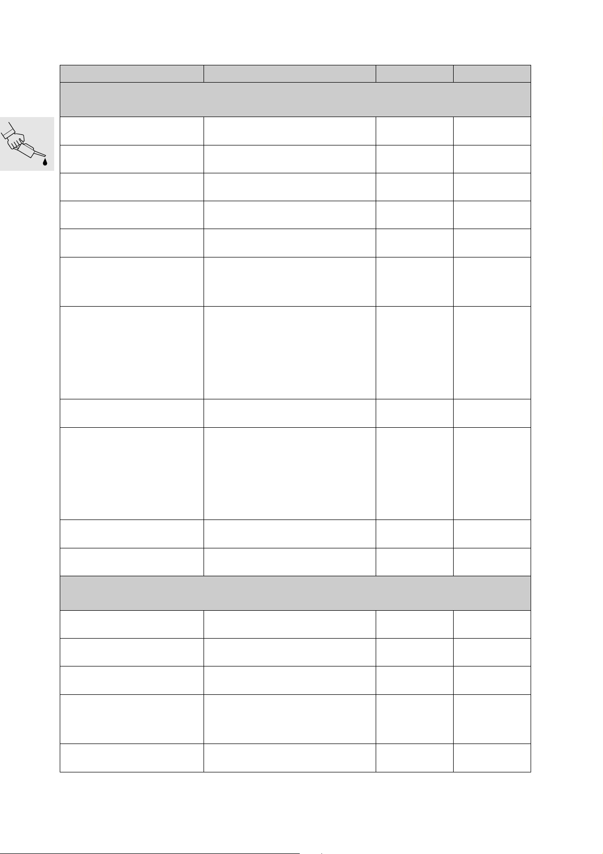
Table of service products
Item Use Order number Quantity
Lubricant
StaburagsNBU30PTM High-performance lubricating paste 07 55 9 056 992
Optimoly MP 3 High-performance lubricating paste 07 55 9 062 476
Optimoly TA High-temperature assembly paste 18 21 9 062 599
Silicone grease 300, heavy Insulation grease 07 58 9 058 193
Retinax EP2
Contact spray Contact spray 81 22 9 400 208
Chain spray Drive chain
Shell HDX2
Klüber paste 46 MR 401
Wheel, steering head and taper roller
bearing grease
Variator rollers
driven variator (pins and bearing)
against fretting corrosion
spacer, variator shaft spline, clutch
drum
crankshaft and outer disc
Shaft seal seats
Ball-bearing seats, shaft journals,
bearing shells, outer ø
Small-end bore, piston pin
83 22 9 407 845
72 60 2 316 676
72 60 2 316 667
11 00 7 660 830
11 00 7 660 831
75 g (2.65 oz)
tube
100 g (3.53 oz)
tube
100 g (3.53 oz)
tube
10 g (0.35 oz)
tube
100 g (3.53 oz)
tube
300 ml
(0.53 Imp pint/
0.32 US quart)
spray
50 ml
(0.088 Imp pint/
0.053 US quart)
spray
300 ml
(0.53 Imp pint/
0.32 US quart)
spray
400 g (14.12 oz)
tube
60 g (2.12 oz)
tube
MOLYKOTE 111
Never Seez Compound Oxygen sensor 83 23 9 407 830
Sealants
3-Bond 1110 B Surface sealant 07 58 9 056 998
3-Bond 1209 Surface sealant 07 58 9 062 376
omni VISC 1002 Surface sealant (max. 200 °C/392 °F) 07 58 1 465 170
Loctite 574 Surface sealant 81 22 9 407 301
Curil K 2 Heat-conductive sealant 81 22 9 400 243
00.12
Water pump, water pump chamber,
shaft seals
11 00 7 660 832
100 g (3.53 oz)
tube
100 g (3.53 oz)
tube
5 g (0.18 oz)
tube
30 g (1.06 oz)
tube
90 g (3.18 oz)
tube
50 ml
(0.088 Imp pint/
0.053 US quart)
tube
250 g (8.83 oz)
can
Page 23
Item Use Order number Quantity
Hylomar SQ 32 M Permanently elastic sealant 81 22 9 400 339
Adhesives and retainers
100 g (3.53 oz)
tube
Loctite 648 Joint adhesive (low clearance) 07 58 9 067 732
Loctite 638 Joint adhesive (greater clearance) 07 58 9 056 030
Loctite 243 Thread retainer, medium-strength 07 58 9 056 031
Loctite 270 Thread retainer, strong 81 22 9 400 086
Loctite 2701 Thread retainer, strong 33 17 2 331 095
Loctite 454 Cyanacrylate adhesive (gel) 07 58 9 062 157
Cleaners
Brake cleaner Brake cleaner 83 11 9 407 848
Metal Polish Polish for chrome-plated parts 82 14 9 400 890
5 g (0.18 oz)
bottle
10 ml
(0.018 Imp pint/
0.010 US quart)
bottle
10 ml
(0.018 Imp pint/
0.010 US quart)
bottle
10 ml
(0.018 Imp pint/
0.010 US quart)
bottle
10 ml
(0.018 Imp pint/
0.010 US quart)
bottle
20 g (0.71 oz)
tube
600 ml
(1.056 Imp pint/
0.634 US quart)
spray
100 g (3.53 oz)
tube
Testing agents
Penetrant MR 68
Developer MR 70
Installation aids
BMW cooling spray
Crack testing agent for aluminium
housings
Crack testing agent for aluminium
housings
Cooling components before assembly
83 19 9 407 855
81 22 9 407 495
83 19 9 407 762
500 ml
(0.880 Imp pint/
0.528 US quart)
spray
500 ml
(0.880 Imp pint/
0.528 US quart)
spray
300 ml
(0.53 Imp pint/
0.32 US quart)
spray
00.13
Page 24

00.14
Page 25

00
00 Pre-delivery check
Contents
Check transport container for damage
Damage in Germany
Damage in export markets
Unpack C1
Place C1 on stand ............................................................................................................................ 19
Take the C1 from the stand ..............................................................................................................21
...................................................................................................................................... 18
Check C1 for damage
.................................................................................................................... 17
....................................................................................................... 17
..............................................................................................................23
..........................................................................17
Page
Check package contents to determine whether consignment is complete
23
Fill and charge the battery
Use BMW MoDiTeC/DIS plus to access stored error codes
Check tyre inflation pressures
Add fuel
............................................................................................................................................ 25
....................................................................................................24
..............................25
............................................................................................25
.
Operation check as final inspection
Final cleaning
Vehicle delivery
............................................................................................................................... 26
............................................................................................................................ 26
................................................................................25
00.15
Page 26

00.16
Page 27

00
Check transport container for damage
Inspect the transport container immediately for
•
damage as soon as the C1 is delivered, remembering to check for collateral damage if indicated
Damage in Germany
Record the damage on the consignment waybill
•
Read transport damage information sheet
•
Inform supplier (freight expediter, rail, etc.) and
•
Bavaria Wirtschaftsagentur GmbH
Abteilung ZW - 12
80788 München
Tel. 089/143 276 32
Fax. 089/143 276 39
immediately
Damage in export markets
Record damage on the consignment waybill
•
National response arrangements apply
•
Submit questions to:
Bavaria Wirtschaftsagentur GmbH
Abteilung ZW - 12
80788 München
Tel. +49 89 143 276 32
Fax. +49 89 143 276 39
Inform supplier (freight expediter, etc.) immedi-
•
ately
00.17
Page 28
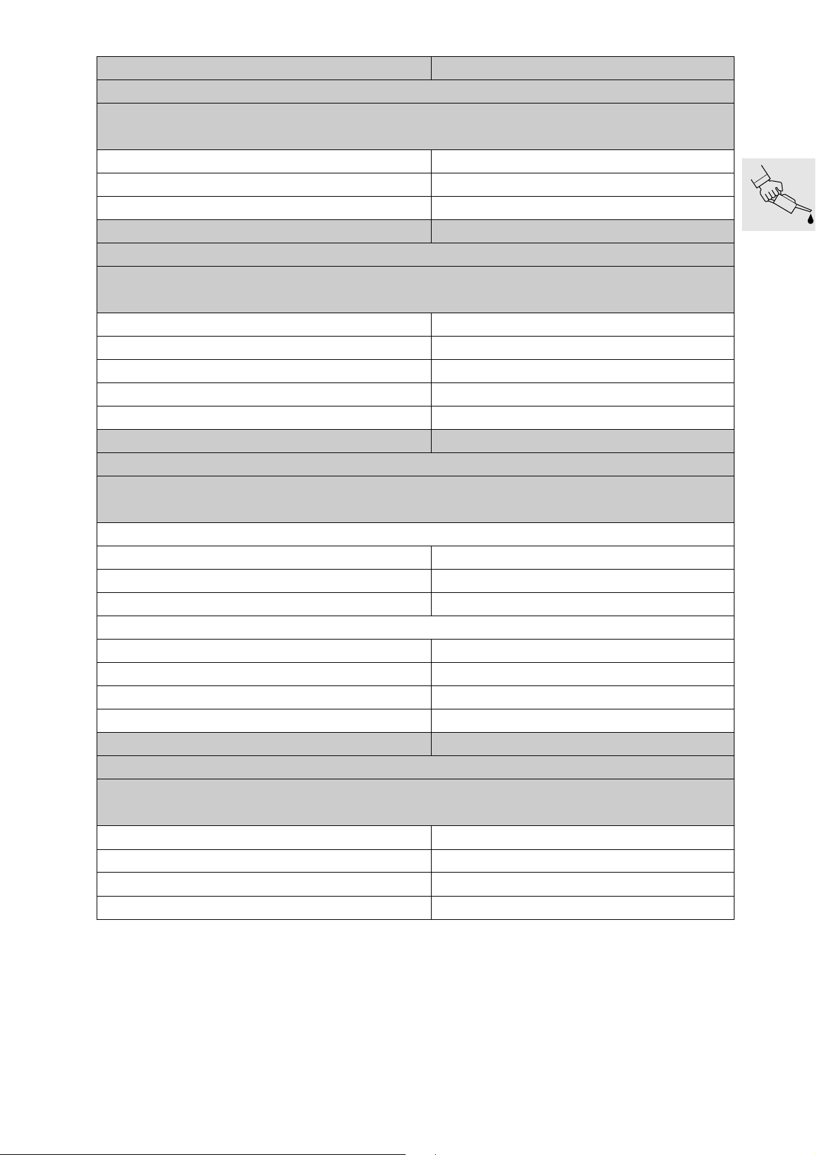
Unpack C1
Open shipping container at strap holes (enlarged
•
openings) on left and right sides
Remove any enclosed packages
•
–Luggage rack
Cut open along the line indicated (follows path of
•
strap)
Dismantle shipping container
•
e
Attention:
Loosen straps without yet removing!
Loosen straps
•
C1000340
C1000350
00.18
e
Attention:
Ensure that it will be possible to fold out the stand!
Page 29
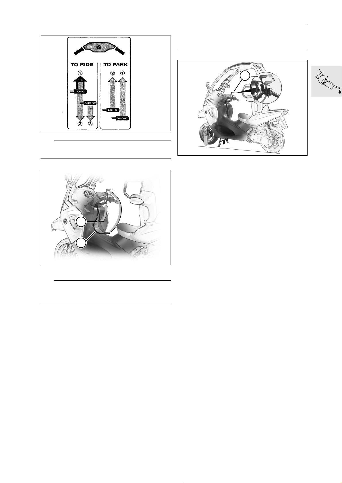
Place C1 on stand
L
Note:
Note instruction plate on instrument trim!
C1000360
L
Note:
The easy-lift mechanism has overload protection.
Fold out the stand with foot if necessary!
1
C1000370
Push up long lever (1) on easy-lift mechanism
•
until it reaches the end of its travel
– The front wheel lifts clear of the ground
– Keep a firm grip on the lever
Slowly move the long lever (1) back until the de-
•
tent engages
Check to verify that the C1 is standing securely
•
2
1
C100BA56
e
Attention:
Excessive strain can damage the easy-lift mechanism!
Hold C1 vertical
•
Centre the handlebar
•
Pull up short lever (2) on easy-lift mechanism
•
– The stand extends
00.19
Page 30
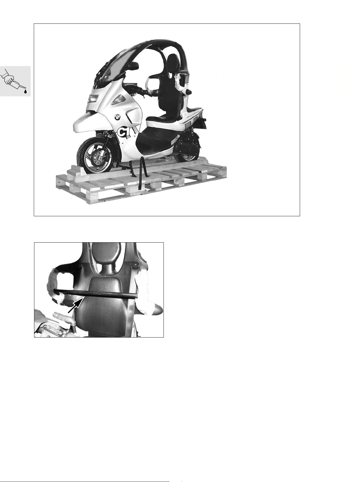
Release and remove straps
•
C1000390
Remove cross member (arrow, shipping brace)
•
C1000380
00.20
Page 31

e
Attention:
Use ramp to avoid damage.
Use ramp from motorcycle hoist, etc.
•
e
Attention:
Clear away any nails lying on the bottom of the shipping container or the shop floor.
C1000400
Take the C1 from the stand
e
Attention:
The stand must be folded all the way back before
the vehicle is rolled down!
Excessive strain can damage the easy-lift mechanism!
00.21
Page 32

Check that the stand is fully retracted
•
L
1
Note:
The easy-lift mechanism has overload protection. If
necessary, use your foot to retract the stand.
Push C1 off the pallet backwards
•
e
Attention:
Make sure the surface under the vehicle is level and
firm!
Do not park the C1 on slopes of more than 6°/12%,
as the stand may fail to provide secure support.
C1000370
Remove weight from vehicle
•
Release long lever (1) from the detent mecha-
•
nism by
– first moving the lever (1) on the easy-lift mecha-
nism all the way forward and up, and then slowly
pushing it downward
– Keep a firm grip on the lever
– The front wheel is lowered to the ground
2
1
C1000410
Hold C1 vertical
•
Push short lever (2) on easy-lift mechanism
•
downward
– The stand retracts
En sure t hat the lo ng lev er (1) is locked at the bot-
•
tom
Place C1 on stand (a 00.19)
•
e
Attention:
Do not cut adhesive tape - can damage shoulder
bar!
C1000420
Remove protective wrap from shoulder bar
•
Dispose of the shipping materials through eco-
•
logically sound channels, refer to bikebox
00.22
Page 33

Check C1 for damage
Record and problems
•
"Early warning card" to
•
BMW Motorrad, UX-VS-1
Fax number 089/382 332 20
+49 89 382 332 20
Rectify problems
•
Order any necessary parts via the electronic
•
parts catalogue
Submit expense claims through GW system
•
(Stage 4) Diagnosis codes:
– Missing parts 10 01 00 00 00
– Damaged parts 10 02 00 00 00
– Incorrect parts delivery 10 03 00 00 00
If required components are not available through the
electronic parts catalogue, please contact the
C1 support staff at UX-VS-2
Phone: 089/382 375 82
+49 89 382 375 82
Check package contents to determine whether consignment is complete
Optional equipment
•
Open rear storage compartment
•
Check contents of enclosed package:
•
On-board tool kit:
•
– Screwdriver with dual insert
– Pair of universal pliers
– Spark plug spanner
–1 angled Allen wrench
Torx T25
– Roadside assistance kit
Vehicle documentation
•
– Rider's Manual
– Service and technology manual
– Remove directory of European dealers from the
factory equipment package and enclose
– BMW roadside assistance service sticker (do-
mestic only)
Vehicle keys, 2
•
Please submit urgent queries and questions concerning technical issues to the C1 support staff at
UX-VS-2
Phone: 089/382 375 82
+49 89 382 375 82
00.23
Page 34

C1000430
Fill and charge the battery
Open cover of rear storage compartment
•
– Remove battery cover
– Remove the battery
a
....................................................See Group 61
d
Warning:
Battery acid is extremely caustic.
Protect your eyes, face, hands, clothing and the
paintwork!
Pull off battery vent hose
•
Remove battery
•
Fill battery with electrolyte, continuing until it
•
reaches upper graduation (arrow)
Allow the battery to stand for at least an hour
•
Shake the battery slightly to allow the remaining
•
air bubbles to escape
Refill to upper graduation as necessary
•
Recharge the battery or allow to stand for
•
24 hours
Charge current (amps)
.....................................10 % of rated capacity (Ah)
Use distilled water to top up the electrolyte, con-
•
tinuing until it reaches the upper graduation
Make a note of the charging date on the battery
•
e
Attention:
Start by tightening the battery' positive terminal,
then proceed to the negative side!
Apply acid-resistant grease to the bettary termi-
•
nals
Installing the battery
•
Install battery cover
•
Close rear storage compartment
•
Fluids and lubricants:
Acid-resistant grease ............................from Bosch
X
Torque specification:
Battery cable to battery terminals................... 3 Nm
00.24
Page 35

Use BMW MoDiTeC/DIS plus to access stored error codes
C1000010
Open seat by inserting ignition key in lock at the
•
left rear
Release backrest mount and remove backrest
•
Connect diagnosis unit to diagnosis plug
•
Access stored error codes
•
Carry out any repair operations indicated
•
Install backrest
•
Check tyre inflation pressures
Check/correct tyre inflation pressures
•
Tyre inflation pressures:
One-up.............................. Front 1.9 bar (27.56 psi)
.......................................... Rear 2.1 bar (30.46 psi)
Full load ............................ Front 2.1 bar (30.46 psi)
.......................................... Rear 2.4 bar (34.81 psi)
Add fuel
Open the seat
•
Pour in fuel
•
Operation check as final inspection
C1000040
Check engine oil
•
Safety belt release mechanism
•
Clutch engagement speed
•
Steering
•
Front and rear brakes
•
Check lights and signalling equipment:
•
– Front and rear parking lamps
– Instrument illumination
– Headlamp, high beam, headlamp flasher
– Brake lamp (actuation of front and rear brakes)
– Left/right turn signals
–Horn
– Indicator and warning lights
– Instruments
Check any optional equipment to confirm that it
•
is operational, check ABS, carry out driving test.
When vehicle is ridden for at least 10 seconds at
over 30 km/h (19 miles/h) the ABS warning lamp
will come on if there any problems in the ABS
Conduct road test as required
•
Confirm delivery in service and technology man-
•
ual
Respond to problems by refering to "Checking
•
C1 for defects"
00.25
Page 36

Final cleaning
Vehicle delivery
Cleaning the C1
•
L
Note:
Do not use steam cleaners or high-pressure spray
wands. High water pressure can lead to damage affecting seals as well as the hydraulic and electrical
systems.
L
Note:
To ensure optimal orientation of every licence plate,
the licence plate holder is not equipped with sockets!
To promote optimal levels of safety and foster satisfaction, the customer should be acquainted with the
C1 as part of the delivery process.
Show/explain the following to the customer:
•
– On-board literature and its storage location
– Owner's manual for description of functions
– Service and technology for service activities on
the C1
– On-board tools and their location
– Operation of the easy-lift mechanism
– Safety belt use - starting lockout
– Central belt release mechanism
– Starting with rear brake engaged - clutch en-
gagement speed
– Windscreen wiper and washer fluid refill cap lo-
cation
– Oil and brake fluid level checks
– Mirror adjustment
– Controls
– Instruments and warning lamps
– Any optional equipment
The customer must be informed of the following:
•
– Break-in information and service intervals
–Helmet laws
–Safety check
00.26
Page 37

00
00 Maintenance
Contents
Maintenance intervals
1,000 km/600 miles Inspection .........................................................................................................31
BMW Service ...................................................................................................................................31
BMW Inspection ...............................................................................................................................31
BMW Annual Service ........................................................................................................................31
Reading out BMW MoDiTeC/DIS and error codes stored in ECU
(Inspections I, II, III and IV) ................................................................................................................31
Engine oil change
(Inspections I, II, III and IV) ................................................................................................................32
Drain engine oil and clean magnetic plug .........................................................................................32
Clean oil filter screen ........................................................................................................................32
Replace oil filter element .................................................................................................................. 32
Refill engine with oil ..........................................................................................................................33
Gearbox oil change
(Inspection III, IV) every 30,000 km/18,000 miles or every 3 years .................................................... 33
Checking coolant
(Inspections I and III) ........................................................................................................................34
Adding coolant .................................................................................................................................34
.............................................................................................................31
...................31
....................................................................................................................... 32
...................................................................................................................33
....................................................................................................................... 34
Page
Change coolant
(Inspection IV, every 2 years) .............................................................................................................35
Drain coolant ....................................................................................................................................35
Draining expansion tank ...................................................................................................................35
Adding coolant .................................................................................................................................35
Checking valve clearances
(Inspections I, II and III) .....................................................................................................................36
Swivel out powertrain cradle
Checking valve clearances
Adjusting valve clearances
Replace spark plug
(Inspections II and III) ........................................................................................................................42
Replacing air cleaner element
(Inspections II and III) ........................................................................................................................43
Empty drain pipe from intake-air plenum chamber
(Inspection IV) ................................................................................................................................... 43
Checking brake lines
(Inspections II and III) ........................................................................................................................44
Checking brake lines ........................................................................................................................ 44
........................................................................................................................... 35
...................................................................................................36
....................................................................................................36
.......................................................................................................38
.......................................................................................................39
...................................................................................................................42
............................................................................................43
................................................. 43
................................................................................................................44
Checking brake system operation and inspect for leaks
(Inspections II and III) ........................................................................................................................ 44
.....................................44
00.27
Page 38

Contents
Page
Checking brake fluid level
(Inspections I, II and III) .....................................................................................................................44
Checking fluid level in the closed brake fluid reservoir
Checking fluid level in the open brake fluid reservoir
Checking brake pads and discs for wear/replacing
(Inspections II and III) ........................................................................................................................46
Checking brake pads for wear
Front brake pads .............................................................................................................................. 46
Rear brake pads ...............................................................................................................................46
Replacing brake pads
Front brake .......................................................................................................................................47
Rear brake ........................................................................................................................................48
.................................................................................................................47
Checking the brake discs
Replacing brake fluid
(Inspection IV) ................................................................................................................................... 50
Front brake
Drawing off brake fluid/forcing back brake pistons ...........................................................................50
Bleed the front brake circuit .............................................................................................................51
....................................................................................................................................... 50
.....................................................................................................44
................................................ 44
................................................... 45
............................................... 46
................................................................................................46
.........................................................................................................49
...............................................................................................................50
Rear brake
Drawing off brake fluid/forcing back brake pistons ...........................................................................51
Bleeding rear brake circuit ................................................................................................................ 52
Variator drive belt replacement
(Inspections II and III) ........................................................................................................................52
Check belt
Checking clutch lining
(Inspection III) ...................................................................................................................................54
Clean variator filter screen
(Inspections II and III) ........................................................................................................................54
Drive variator
Remove drive variator
Check, clean and grease drive variator (lubricated version)
(Inspection II, III) (lubricated version) .................................................................................................55
Check and clean drive variator (unlubricated version)
(Inspection II, III) (unlubricated version) ............................................................................................. 57
........................................................................................................................................ 51
..........................................................................................52
........................................................................................................................................ 53
.............................................................................................................54
....................................................................................................54
................................................................................................................................. 55
.................................................................................................................55
......................................55
................................................. 57
Replacing complete drive variator
(Inspection II) every 22,500 km (13,500 miles) – lubricated version only ...........................................58
Checking wheel bearing float
(Inspection III) ...................................................................................................................................59
00.28
....................................................................................58
..............................................................................................59
Page 39

Contents
Page
Check to ensure that leading link bearing has zero play
(Inspection I, IV) ................................................................................................................................60
Checking steering bearing play ........................................................................................................60
Check battery electrolyte level - add distilled water if necessary
(Inspection IV) ................................................................................................................................... 60
Checking battery electrolyte level
Adding distilled water .......................................................................................................................61
Clean/grease battery terminals if necessary
(Inspection IV) ................................................................................................................................... 61
Checking Bowden cables
(Inspections III and IV) ......................................................................................................................61
......................................................................................................61
Checking windscreen washer
(Inspections I, II and III) .....................................................................................................................62
Check windscreen wiper
(Inspections II, III and IV) ...................................................................................................................62
Checking safety elements
(Inspections I, II, III and IV) ................................................................................................................62
.......................................................................................................62
.....................................................................................................62
Check Bowden cable for central seat-belt release
..........................................................................................60
.............................................................. 61
.............................................................................................62
........................................................ 62
.....................................60
..................60
Check belt straps and belt buckles
Check inertia reels
....................................................................................................................... 62
......................................................................................62
Check inertia-reel's detent mechanism to ensure that it engages correctly
Examine crash elements
(Inspections I, II, III and IV) ................................................................................................................63
Check shoulder bar and deformation element
(Inspections I, II, III and IV) ................................................................................................................63
Measure shoulder bar
Replacing fuel filter
(Inspection II) every 37,500 km (22,500 miles) .................................................................................. 63
...................................................................................................................63
........................................................................................................63
.......................................................... 63
.................................................................................................................63
Replacing boot in brake-control assembly (master cylinder), only
with optional ABS
(Inspection III) every 30,000 km (18,000 miles ) ................................................................................. 64
Check mounts
(Inspection I) .....................................................................................................................................65
Final inspection with road safety and operation check
(Inspections II, III and IV) ................................................................................................................... 65
Tyre tread depth (recommended minimum) .......................................................................................65
Tyre pressures (tyres cold) ................................................................................................................65
Roadworthiness check .....................................................................................................................65
....................................................................................................................... 64
.............................................................................................................................. 65
........................................ 65
......62
00.29
Page 40

00.30
Page 41

00
Maintenance intervals
1,000 km/600 miles Inspection
BMW Break-in Inspection after the initial 1,000 km/
600 miles
BMW Service
At the end of the first 7,500 km/4,500 miles
and then at intervals of 15,000 km/9,000 miles,(at
22,500 km, 37,500 km…/13,500 miles,
22,500 miles… )
BMW Inspection
At the end of the first 15,000 km/9,000 miles
and then at intervals of additional 15,000 km/
9,000 miles,(at 30,000 km, 45,000 km…/18,000 miles,
27,000 miles…)
BMW Annual Service
Although many service operations are scheduled
according to milage, many procedures (such as
brake fluid changes) should be carried out at least
once a year, regardless of elapsed milage.
If these operations are not performed in the course
of a standard, milage-based Service or Inspection,
an extra visit for an Annual Service will be required.
The codes for service and maintenance intervals in
this repair manual are as follows:
Reading out BMW MoDiTeC/DIS and error codes stored in ECU
(Inspections I, II, III and IV)
Open the seat
•
Remove the backrest
•
C1000010
Connect
•
ble to diagnostic interface (arrow)
L
Note:
Follow the instructions in the diagnosis program.
MoDiTeC/DIS plus diagnosis ca-
BMW
– BMW Inspection at 1,000 km/600 miles ............
– BMW Maintenance Service every
7,500 km/4,500 miles .......................................
– BMW Inspection every 15,000 km/9,000 miles
– BMW Annual Service ......................................
Operations specified for extended-milage vehicles:
a
Replacement of complete drive variator (
a
............................. Refer to Assembly Group 24
.......................................... for more information
Vehicles with ABS: replace handbrake fittings (rubber diaphragm on brake master cylinder) (
a
............................. Refer to Assembly Group 32
.......................................... for more information
Replace fuel filter (a00.63)
a
............................. Refer to Assembly Group 16
.......................................... for more information
00.58)
a
00.64)
I
II
III
IV
00.31
Page 42

Engine oil change
(Inspections I, II, III and IV)
Drain engine oil and clean magnetic plug
Clean oil filter screen
L
Note:
Drain the engine oil only after the engine has
warmed to normal operating temperature!
e
Attention:
Observe all safety precautions when allowing an internal-combustion engine to run in an enclosed area!
1
Unscrew oil filter screen bolt (2)
•
Clean oil filter screen
•
Replace oil filter element
2
C1000022
11 7 661
Unscrew magentic oil drain plug (1)
•
Clean magnet
•
C1000022
Secure oil guard
•
haust
Unscrew oil filter cover bolts (arrows)
•
BMW No. 11 7 661
C1000330
to the ex-
00.32
BMW recommends Castrol
Page 43

Fluids and lubricants:
Engine oil ................................ 1.0 l/1.76 Imp pints
Brand- name HD oi l, AP I cl a ssi fica tion SF, S G or S H;
suffix letters CD or CE are approved; alternatively,
brand-name HD oil with CCMC classification G4 or
G5; suffix PD2 is permitted.
X
Tightening torque:
Oil filter cover ............................................... 10 Nm
Magnetic oil drain plug ................................. 20 Nm
Oil filter screen attachment bolt.................... 30 Nm
Replace oil filter element
•
Refill engine with oil
L
Note:
Replace drain plug seal rings!
C1000030
C1000040
Gearbox oil change
(Inspection III, IV) every 30,000 km/18,000 miles
or every 3 years
1
Unscrew oil drain plug (1)
•
Pour gearbox oil in filler opening (2)
•
Fluids and lubricants:
GL 4 gear lubricant ................ 0.09 l/0.16 Imp pints
2
C1000500
Add engine oil through oil filler neck
•
Add oil up to the MAX mark on the dipstick
•
Run the engine briefly, then switch it off and
•
check oil level again: add oil if necessary
Check coolant level and top up as required
•
00.33
Page 44

Checking coolant
Adding coolant
(Inspections I and III)
max
min
C1000050
L
Note:
Check coolant level only with the engine cold!
Open the seat and check the coolant level
•
Maximum level ............................................
Minimum level ..............................................
"max"
"min"
– Remove the backrest
1
2
C1000060
Remove cap (1) from expansion tank (2)
•
e
Attention:
Add or refill coolant only when engine is cold. Add
coolant to expansion tank only if a small quantity has
been lost. Otherwise refill with coolant (a17.15).
Reinstall cap (1)
•
00.34
Page 45

Change coolant
(Inspection IV, every 2 years)
Drain coolant
– Remove front fairing panel
– Loosen radiator cap
C1000071
Adding coolant
Pour coolant into filler neck
•
C1170290
Slip hose (arrow) over screw head
•
Remove drain plug
•
Drain coolant
•
L
Note:
Replace drain plug seal!
Tighten drain plug
•
X
Torque specification:
Drain plug..................................................... 10 Nm
Draining expansion tank
L
Note:
If powerplant cradle is pivoted expansion tank may
be accessed under lock fitting. Alternatively, draw
off coolant with a syringe or similar.
1
C1000080
Open vent screw (1) in cylinder head to bleed air
•
from system, reclosing only after coolant starts
to emerge
To top up coolant in expansion tank
•
Run the engine briefly, then stop it, recheck cool-
•
ant level and top up if necessary
Capacities:
Cooling system ...................... 1.25 l/2.20 Imp pints
Expansion tank ........................ 0.2 l/0.35 Imp pints
e
Attention:
Use only nitrite-free extended-duty antifreeze with
corrosion inhibitor!
Mixture ratio:
Water .............................................................. 50%
Antifreeze.........................................................50%
Protection down to .............................—25 °C/77 °F
00.35
Page 46

Checking valve clearances
(Inspections I, II and III)
Swivel out powertrain cradle
Secure front wheel
•
Remove wiring from clip (arrow):
•
- Alternator
- Ignition unit
C1000090
Remove wiring from clip:
•
- Injector
- Air temperature sensor
- Idle actuator
- Coolant temperature sensor in cylinder head
C1000110
Open the seat
•
C1000100
Release clip and disconnect plug from oxygen
•
sensor (arrow)
C1000120
Release coolant hose from clamp at injector and
•
on variator cover bracket (arrow)
00.36
Page 47

C1000130
e
Attention:
To avoid stretching hoses and lines, do not swivel
the powertrain cradle more than 20°!
Lift C1 no further than stop: powertrain cradle
•
swivels down
When installing:
Install the cylinder head cover before swiveling
•
the powertrain cradle back into place
e
Attention:
Ensure that gasket and cover are free of oil!
Remove hose from bracket on intake-air plenum
•
chamber (arrow)
33 1 531
00 1 580
00 1 570
C1000140
Position vehicle jack
•
tachment
Raise the vehicle slightly
•
Install fixture,
•
spring strut and powertrain cradle
Remove lower end of right spring strut from
•
brake caliper holder
BMW No. 00 1 580
BMW No. 33 1 531,
BMW No. 00 1 570
at separation point
between left
with at-
Installing cylinder head cover
•
e
Attention:
When lowering note positions of struts and intakeair plenum chamber!
L
Note:
Ensure that the detent engages to secure the long
lever on the easy-lift mechanism. If necessary, move
the lever to the drive position first, and then move it
to the park position.
X
Tightening torque:
Cylinder head cover ..................................... 10 Nm
Strut, lower .................................................. 21 Nm
00.37
Page 48

Checking valve clearances
– Remove left and right service covers
– Swivel out powerplant cradle
17 5 500
1
Open hose clamp (arrow) with pliers
•
BMW No. 17 5 500
Unscrew cylinder head cover bolts (1)
•
C1000150
C1111001C1000170
Measure valve clearance using single feeler
•
gauge blade
Record the valve clearances
•
and adjust valve clearance as indicated (replace
•
valve lifters)
Specified clearances:
C1000160
Watch throttle (arrow)
•
Remove spark plug
•
Use camshafts to rotate engine until the lobes
•
are pointing outward
IV left
mm (in)
0.05
Spec.
clearance
Clearance,
measured
(used)
Difference
Inlet valve clearance........................0.05…0.09 mm
............................................ (0.00197…0.00354 in)
Exhaust valve clearance..................0.20…0.29 mm
............................................ (0.00787…0.01147 in)
(0.00197)
0.09
(0.00354)
0.15
(0.00590)
0.01
(0.00039)
IV right
mm (in)
0.05
(0.00197)
0.09
(0.00354)
EV left
mm (in)
0.20
(0.00787)
0.29
(0.01147)
0.15
(0.00590)
-0.05
(-0.00197)
EV right
mm (in)
0.20
(0.00787)
0.29
(0.01147)
00.38
Page 49

Adjusting valve clearances
To foster enhanced clarity, some of the illustrations
show components with the powerplant cradle removed
– Swivel out powerplant cradle
– Checking valve clearances
C1130010
Loosen hose clamp (arrow) on intake-air plenum
•
chamber
11 7 651
C1000220
Remove Allen bolt adjacent to starter and use
•
special bolt,
L
Note:
Because the round cover plate can rotate against
the gear, the TDC mark should always be made on
the gear itself - not on the cover plate
BMW No. 11 7 651,
to lock at TDC
C1000200
L
Note:
Watch for dirt and contamination around the starter/
threaded plug (arrow) - no contamination in engine!
C1000180
Use a coloured marker to mark TDC (arrow) on
•
the inlet camshaft's sprocket
00.39
Page 50

Release chain tensioner bolt (arrow)
•
C1000231
L
Note:
Watch bolt length and take care to install in correct
positions,
lettering is to the outside, use coloured marker to
identify end as necessary!
C1000190
Detach mounts (arrows) from chain guide and re-
•
move
C1110910
Press chain tensioner to the outside using chain
•
tensioning rail
L
Note:
The bolts on the chain guide mechanism are secured with thread-locking compound!
L
Note:
The camshafts can also be removed and installed
with the sprockets in place!
L
Note:
The camshaft sprocket is secured with locking compound!
Undo bolts and remove camshaft sprokets
•
L
Note:
Make sure that the timing chain does not drop into
the housing. Use a retainer to keep timing chain tensioned at all times!
Secure the timing chain to prevent it from falling
•
00.40
Page 51

L
Note:
Note the length of the bolts used to attach the camshaft bearing cap!
C1000232
Subtract negative difference of bucket (old)
•
Add positive difference of bucket (old)
•
Note sizes of available bucket tappets
•
L
Note:
The bucket tappets are available in sizes ranging
from 2.50 mm (0.09842 in) to 3.20 mm (0.12598 in)
in 5/100ths graduations.
Should it prove impossible to adjust the valve clearance with the smallest bucket tappet (2.50 mm/
0.09842 in) the cylinder head will have to be re-
a
placed (
If it is not possible to adjust the valve clearance with
the largest bucket tappet (3.20 mm/0.12598 in) the
valve seat will have to be reground (a11.30).
When installing:
While installation is basically a reversal of the re-
•
moval process, careful attention should be directed toward the following operations:
11.40).
Remove 8 bolts
•
Remove camshaft bearing cap
•
Removing camshafts
•
Remove camshaft bearing seat
•
Remove the tappet
•
Record the figures on the bottoms of the tappets
•
Sample calculation:
Spec.
clearance
Clearance,
measured
(used)
Difference
Bucket,
measured
(used)
Bucket
specification (new)
Bucket,
measured
(new)
Clearance
specification (new)
IV left
mm (in)
0.05
(0.00197)
0.14
(0.00551)
0.15
(0.00590)
0.01
(0.00039)
2.80
(0.11023)
2.81
(0.11062)
2.85
(0.11220)
0.10
(0.00394)
IV right
mm (in)
0.05
(0.00197)
0.14
(0.00551)
EV left
mm (in)
0.20
(0.00787)
0.29
(0.01147)
0.15
(0.00590)
-0.05
(-0.00197)
2.80
(0.11023)
2.75
(0.10826)
2.75
(0.10826)
0.20
(0.00787)
EV right
mm (in)
0.20
(0.00787)
0.29
(0.01147)
e
Attention:
The grooves in the bearing caps are oil passages!
Note the lengths of the camshaft bearing cap bolts!
C1110111
e
Attention:
Align bearing caps, make sure that bearing caps
and bearing seats are correctly aligned. Run a finger
along the joint to check alignment!
Remove traces of Loctite from threads of cam-
•
shafts and chain guide
Coat threads of fasteners for chain guide and
•
camshaft gear with Loctite
The inlet camshaft bears a punch mark (arrow) as
•
identification
Make sure that the camshafts turn easily and
•
smoothly
Clearance,
measured
(new)
00.41
Page 52

L
Note:
Always renew the screw plug's sealing ring!
Install chain tensioner (a11.33)
•
e
Attention:
Remove TDC set bolt,
BMW No. 11 7 651.
Replace spark plug
(Inspections II and III)
– Remove left service cover
Turn the engine over several times by hand
•
Check valve clearance and adjust as necessary
•
L
Note:
Install cover seal, ensuring that it and groove in cylinder head cover are free of oil!
Install the cylinder head cover before installing
•
the powertrain cradle
e
Attention:
When lowering note the positions of the spring
struts!
L
Note:
Make sure the long lever of the easy-lift mechanism
engages. If necessary, move the lever to the drive
position first, and then move it to the park position!
Fluids and lubricants:
Guide rail............................................... Loctite 243
Camshaft sprocket ................................ Loctite 243
12 3 531
C1120030
Disconnect spark plug cap
•
Use spark-plug wrench,
•
remove spark plug
X
Torque specification:
Spark plugs.................................................. 15 Nm
Fluids and lubricants:
Spark plug .........................................NGK CR 8EB
BMW No. 12 3 531,
to
X
Torque specification:
Guide rail attachment ................................... 10 Nm
Camshaft sprockets .................................... 30 Nm
Camshaft bearing cap bolt ........................... 10 Nm
TDC bolt socket plug ................................... 15 Nm
Chain tensioner plug .................................... 35 Nm
Lower strut mount ........................................ 21 Nm
00.42
Page 53

Replacing air cleaner element
(Inspections II and III)
1
Empty drain pipe from intake-air plenum chamber
(Inspection IV)
Empty the drain pipe from the air cleaner housing
•
C1130010
Remove fasteners (1) securing cover to air filter
•
housing
Replace air filter element
•
C1000130
Remove plug (arrow) and allow oil which has
•
drained out to escape
Assembly is the reverse of the dismantling pro-
•
cedure
00.43
Page 54

Checking brake lines
Turn the handlebars at full left-hand lock
•
(Inspections II and III)
e
Attention:
Refer to and observe the precautions for handling
brake fluid!
Check brake calipers, unions and lines on brake
•
system for correct operation, leaks, damage and
incorrect positioning; repair or replace as necessary
Check the brake fluid level and top up if neces-
•
sary
Checking brake lines
Examine all brake lines for damage and correct
•
routing
Checking brake system operation and inspect for leaks
(Inspections II and III)
Check condition and routing of all lines and con-
•
nections
Checking brake fluid level
(Inspections I, II and III)
Checking fluid level in the closed brake fluid reservoir
The procedure for checking the level in the left brake
fluid reservoir is described below. The procedure for
checking the level in the right brake fluid reservoir is
basically the same.
L
Note:
The volume of the brake fluid (MIN/MAX) is sufficient
for lining thicknesses from new to the wear limit. It is
not normally necessary to top up the fluid to accommodate lining wear.
A level below MIN indicates the possibility of other
system defects!
C1340430
Check the level of brake fluid through the sight
•
glass
Minimum level (arrow)
............. slightly above the centre of the sight glass
wear limit with worn brake pads
d
Warning:
The brake fluid level must never be allowed to fall
below the MIN mark (arrow) used to identify the absolute minimum level. Otherwise, there is a danger
that air will be drawn into the brake system during
operation!
e
Attention:
The fluid level in the brake fluid reservoir must be at
the “MAX” mark with new brake pads. It is not possible to verify that the fluid is at maximum level
through the sight glass. For details on the correct
procedure see
brake fluid reservoir!
00.44
Checking fluid level in the open
Page 55

Checking fluid level in the open brake fluid reservoir
The procedure for checking the level in the left brake
fluid reservoir is described below. The procedure for
checking the level in the right brake fluid reservoir is
basically the same.
e
Attention:
Do not allow brake fluid to come into contact with
painted parts of the motorcycle - brake fluid attacks
paintwork!
L
Note:
Do not remove the reservoir cap unless the handlebar is turned all the way to the right!
Turn the handlebar all the way to the right
•
Secure the handlebar in the full lock position
•
1
MAX
C1340450
Specification:
Specified level with new pads
...................... Upper edge on inside of sight glass
e
Attention:
When adding brake fluid, do not allow it to enter the
holes for the reservoir cap screws!
If the brake fluid level does not come up to the
•
top of the sight glass with new brake pads installed top up the fluid level and, if necessary,
check the brake system for leaks
Remove reservoir cap (1) with diaphragm
•
C1340440
When installing:
While installation is basically a reversal of the re-
•
moval process, careful attention should be directed toward the following operations:
L
Note:
Wipe the rim of the reservoir, the rubber boot and
the cover to remove brake fluid, and carefully reassemble the components!
Hand-tighten cap on reservoir
•
Check operation of the brake system
•
Operating fluid:
Brake fluid.....................................................DOT 4
00.45
Page 56

Checking brake pads and discs for wear/replacing
(Inspections II and III)
Checking brake pads for wear
d
Warning:
Never allow brake pads to wear below the minimum
specified thickness!
Always replace pads as a complete set!
Front brake pads
Rear brake pads
C1340360
Visually inspect the brake pads from behind
•
– Replace the brake pads if a wear mark (arrows) is
no longer clearly visible
C1340340
Visually inspect the brake pads from behind and
•
below
– Replace the brake pads if a wear mark (arrows) is
no longer clearly visible
MIN
C1340350
Minimum pad thickness
The brake pads have a clearly visible chamfer (arrow) as a wear indicator
MIN
C1340370
Minimum pad thickness
The brake pads have a clearly visible chamfer (arrow) as wear indicator
00.46
Page 57

Replacing brake pads
Front brake
e
Attention:
Never separate the two sections of the brake caliper!
Firmly press the brake caliper against the brake
•
disc in order to force back the brake pads and
pistons
L
Note:
If the brake pads/pistons cannot be forced back in
this way, this can indicate a defect in the brake system!
21
C1340380
Remove the cotter pin (2) from the dowel pin (1)
•
1
34 1 541
C1340390
Remove dowel pin (1) with drift punch or pliers,
•
BMW No. 34 1 541
Remove the brake pads.
•
When installing:
While installation is basically a reversal of the re-
•
moval process, careful attention should be directed toward the following:
e
Attention:
Do not damage the brake pads when installing!
Checking operation of the brake system
•
e
Attention:
The fluid level in the brake fluid reservoir must be at
the “MAX” mark after the brake pads have been
changed. It is not possible to determine whether the
fluid is at the specified maximum level using the
sight glass. For details on the correct procedure see
Checking fluid level in the open brake fluid reservoir!
00.47
Page 58

Rear brake
e
Attention:
Never separate the brake caliper sections!
1
C1340400
Detach the lower end of the strut (1) and tie it up
•
out of the way
e
Attention:
Avoid scratching or otherwise damaging the wheel
rim, mask off brake caliper if necessary!
L
Note:
If the brake pads/pistons cannot be forced back in
this way, this may indicate a defect in the brake system!
34 1 570
1
2
C1340411
Remove the cotter pin (1) from dowel pin (2)
•
Remove dowel pin (2) with extractor,
•
BMW No. 34 1 570
Pull out the brake pads toward the rear
•
1
2
C1340020
Firmly press the brake caliper against the brake
•
disc in order to force back the brake pads and
pistons
1
Pull support plate (1) back and up
•
C1340470
00.48
Page 59

1
C1340480
Remove support plate (1) to the inside
•
When installing:
While installation is basically a reversal of the re-
•
moval process, careful attention should be directed toward the following operations:
e
Attention:
Always replace the backplate!
Ensure that the backplate seats correctly!
Take care to avoid damaging brake pads when installing!
Checking the brake discs
Carefully check the brake discs for cracking,
•
damage, deformation and scoring
C1340420
Measure the thickness of the brake discs at sev-
•
eral points with a caliper gauge
Wear data:
Front brake discs ..................... 4.0 mm/0.15748 in
Rear brake disc........................ 4.0 mm/0.15748 in
Install new backplate
•
Use a long-nosed punch to install the dowel pin
•
Check the operation of the brake system
•
e
Attention:
The fluid level in the brake fluid reservoir must be at
the “MAX” mark after the brake pads have been
changed. It is not possible to determine whether the
brake fluid is at the specified maximum level through
the sight glass. For details on the correct procedure
see
Checking fluid level in the open brake fluid
reservoir!
00.49
Page 60

Replacing brake fluid
(Inspection IV)
e
Attention:
Protect trim panels against contact with brake fluid!
e
Attention:
Observe all precautions for handling brake fluid!
e
Attention:
To ensure continued safety the brake fluid must be
changed annually!
The brakes must be bled and checked to ensure
that they are in full working order!
Vehicles with ABS
e
Attention:
On vehicles with
erations in the repair manual must be supplemented
by bleeding operations performed using the
MoDiTeC/DIS plus with the ABS control units
BMW
toolbox.
There is a danger that residual air will remain in the
ABS control circuits if
not used.
Connect a commercially-available suction device
•
to the brake fluid bleed screws on the caliper
Force the pistons all the way back into the brake
•
calipers
L
Note:
This description applies to the brake filling and
bleeding units that operate using suction at the
bleed fitting on the brake caliper.
If other devices are used, comply with their manufacturers' instructions!
the brake system service op-
ABS
MoDiTeC/DIS plus is
BMW
Front brake
e
Attention:
Do not allow brake fluid to come into contact with
painted parts of the motorcycle - brake fluid attacks
paint!
Drawing off brake fluid/forcing back brake pistons
Firmly press the brake caliper against the brake
•
disc in order to force back the brake pads and
pistons
L
Note:
If the brake pads/pistons cannot be forced back in
this way, there may be some defect in the brake system!
Connect the brake bleeding device to the bleed
•
screw on the brake caliper
Open the bleed screw by half a turn
•
Draw off brake fluid from the front brake circuit
•
When installing:
Installation is the reverse of the removal proce-
•
dure
e
Attention:
On vehicles with
described in the repair manual must be supplemented by bleeding operations using the
MoDiTeC/DIS plus with the ABS control unit
BMW
toolbox.
Failure to use the
a hazard of residual air remaining in the ABS control
circuits.
Add brake fluid until it reaches the top of the
•
sight glass
Bleed the front brake circuit
•
Check the operation of the brake system
•
the brake service operations
ABS
MoDiTeC/DIS plus results in
BMW
00.50
Page 61

Bleed the front brake circuit
e
Attention:
On vehicles with
described in the repair manual must be supplemented by bleeding operations using the
MoDiTeC/DIS plus with the ABS control unit
BMW
toolbox.
Failure to use the
a hazard of residual air remaining in the ABS control
circuits.
– Add brake fluid until it reaches the top of the
sight glass
Connect the brake bleeding device to the bleed
•
screw on the brake caliper
Bleed vehicle with
[ABS]
•
•
e
Brake fluid level must not drop below the MIN mark
during the bleeding process, otherwise air will be
drawn into the brake system. Bleed the system
again if this happens!
MoDiTeC/DIS plus
BMW
Open the bleed screw by half a turn
Attention:
the brake service operations
ABS
MoDiTeC/DIS plus results in
BMW
Rear brake
e
Attention:
Do not allow brake fluid to come into contact with
painted parts of the motorcycle - brake fluid attacks
paint!
Drawing off brake fluid/forcing back brake pistons
e
Attention:
Avoid damaging or scratching the brake caliper;
mask it off if necessary!
Continue to extract brake fluid until it emerges
•
clear and free of air bubbles
Tighten the bleed screw
•
Check the operation of the brake system
•
Operating fluid:
Brake fluid .....................................................DOT 4
X
Torque specification:
Bleed screw ................................................. 14 Nm
C1340020
Firmly press the brake caliper against the brake
•
disc in order to force back the brake pads and
pistons
L
Note:
If the brake pads/pistons cannot be forced back in
this way, there may be some defect in the brake system!
Connect the brake bleeding device to the bleed
•
screw on the brake caliper
Extract brake fluid from the rear brake circuit
•
00.51
Page 62

When installing:
Installation is the reverse of the removal proce-
•
dure
– Add brake fluid up to the top of the sight glass
– Bleed the rear brake circuit
Check the function of the brake system
•
Bleeding rear brake circuit
e
Attention:
On vehicles with
described in the repair manual must be supplemented by bleeding operations using the
MoDiTeC/DIS plus with the ABS control unit
BMW
toolbox.
Failure to use the
in a hazard of residual air remaining in the ABS control circuits.
– Add brake fluid until it reaches the top of the
sight glass
Connect the brake bleeding device to the bleed
•
screw on the brake caliper
Bleed vehicle with
[ABS]
•
•
MoDiTeC/DIS plus
BMW
Open the bleed screw by half a turn
the brake service operations
ABS
MoDiTeC/DIS plus results
BMW
Variator drive belt replacement
(Inspections II and III)
1
C1000240
Remove fasteners (1)
•
Remove vent cover
•
e
Attention:
Brake fluid level must not drop below the MIN mark
during the bleeding process, otherwise air will be
drawn into the brake system. Bleed the system
again if this happens!
Extract brake fluid until it emerges clear and free
•
of air bubbles
Tighten the bleed screw
•
Check the operation of the brake system
•
Operating fluid:
Brake fluid .....................................................DOT 4
X
Torque specification:
Bleed screw ................................................. 14 Nm
2
C1000250
Remove fasteners (2)
•
Remove variator cover
•
When installing:
Note positions of vent hose and bracket (arrow)
•
00.52
Page 63

Check belt
Check for cracks
•
Check width of belt
•
Wear data:
Belt width ....................................17.8 mm/0.701 in
When installing:
The legend on the belt must be visible from the outside
11 7 521
C1000261
Use retainer,
•
terpressure and remove the attachment from the
driven variator
Press variator plates together and turn them an-
•
ticlockwise
Remove belt together with driven variator
•
Clean housing and variator cover
•
BMW No. 11 7 521,
to apply coun-
C1000270
Make sure the belt is correctly seated
•
Install belt together with driven variator
•
Check by turning variator manually to ensure that
•
belt is not trapped
X
Torque specification:
Driven variator mount ................................... 60 Nm
00.53
Page 64

Checking clutch lining
Clean variator filter screen
(Inspection III)
H
h
C1110540
Remove bell housing; use puller if necessary
•
Check clutch plate lining replace if necessary
•
L
Note:
Replacing driven variator without clutch (a24.6).
a
................................................... See Group 21
(Inspections II and III)
Remove fasteners (1)
•
Remove vent cover
•
1
C1000240
Wear data:
Pad, wide H............................... 4.0 mm/0.15748 in
Pad, narrow h............................2.5 mm/0.09842 in
Remove filter screen from retaining lugs and
•
clean
Clean inside of vent cap
•
C1000280
00.54
Page 65

Drive variator
Remove drive variator
L
Note:
The following description of variator removal applies
to both the lubricated and the unlubricated versions!
Note differences during assembly!
11 7 521
Check, clean and grease drive variator (lubricated version)
(Inspection II, III) (lubricated version)
C1000440
C1000291
L
Note:
The nut is secured with thread-locking compound!
Undo nut (arrow) using retainer
•
BMW No. 11 7 521
Remove outer washer and drive variator with
•
spacer
Clean locking compound from threads on crank-
•
shaft
When installing:
While installation is basically a reversal of the re-
•
moval process, careful attention should be directed toward the following operations:
Observe assembly instructions for lubricated
•
(a00.56) and unlubricated variators (a00.58)
1
2
3
4
6
5
7
C1110491
Undo attachment bolts (5) and remove cover (4)
•
Remove driver (3) and sliders (2) with spring clips
•
Remove rollers (1)
•
Clean all parts with shop towels
•
Check shaft sealing rings for damage and cor-
•
rect seating
Check O-ring (7) for damage and flat spots
•
L
Note:
The bearing tube (7) (spacer) is equipped with a
continuous lubrication passage (arrow)! Install only
bearing tube with lubrication passage on lubricated
versions of the drive variator!
00.55
Page 66

C1000480
When installing:
While installation is basically a reversal of the re-
•
moval process, careful attention should be directed toward the following operations:
L
Note:
The rollers in the frame may display flat spots within
the wear limits!
Wear within the specified wear limits is acceptable!
Visible, palpable roller wear (arrows) on the drive
plate's tracking surfaces is acceptable!
Conduct visual inspection
•
Replace drive variator as required
•
C1111300
Evenly apply approximately 20 g (0.7 oz) of
•
grease to the contact path of the inner plate
Lightly grease O-ring and install
•
Place spring, sliders on transfer elementand
•
grease recesses in sliders
L
Note:
The bearing tube (spacer) is equipped with a continuous lubrication passage! Install only bearing tube
with lubrication passage on lubricated version of
drive variator!
Apply even coat of grease to inside of bearing
•
tube (spacer)
Spray ground faces of crankshaft stub
•
Place transfer element in position
•
Check action of transfer element
•
Secure variator cover
•
Fluids and lubricants:
Shell Retinax HDX2 .......approximately 20 g (0.7 oz)
Spacer and contact
surface ..............................Klüber paste 46 MR 401
Crankshaft stub.................Klüber paste 46 MR 401
00.56
X
Torque specification:
Variator cover attachment .............................. 4 Nm
Drive variator attachment
(+ LOCTITE 243) .......................................... 60 Nm
Variator cover............................................... 10 Nm
Vent cover...................................................... 9 Nm
Page 67

Check and clean drive variator (unlubricated version)
(Inspection II, III) (unlubricated version)
C1000450
1
2
C1000470
L
Note:
Flat spots on the rollers that do not not exceed the
wear limits are acceptable!
Wear within the specified limits is acceptable!
Visible and palpable contact tracks (arrows) caused
by motion of rollers through their travel paths are acceptable!
3
5
Remove transfer element (3), then extract
•
sliders (5) with spring (4)
Remove rollers (1)
•
Clean all parts with shop towels
•
L
Note:
The bearing tube (2) (spacer) does not have a lubrication passage!
4
C1000460
Conduct visual inspection
•
Replace drive variator as necessary
•
00.57
Page 68

When installing:
While installation is basically a reversal of the re-
•
moval process, careful attention should be di-
rected toward the following operations:
C1000490
Do not lubricate drive variator during assembly or
•
installation -
Check action of transfer element
•
do not
grease
Replacing complete drive variator
(Inspection II) every 22,500 km (13,500 miles) –
lubricated version only
11 7 521
C1000291
L
Note:
The nut is secured with thread-locking compound!
X
Torque specification:
Drive variator mount
(+ LOCTITE 243)........................................... 60 Nm
Variator cover............................................... 10 Nm
Vent cover...................................................... 9 Nm
Use retainer
•
plate, then remove drive variator with spacer
Clean locking compound from crankshaft
•
threads
Clean housing and variator cover
•
BMW No. 11 7 521
to undo outside
C1000300
00.58
Page 69

When installing:
Observe installation instructions for lubricated
•
(a00.56) and unlubricated variator (a00.58)
Spray shaft as necessary
•
Fluids and lubricants:
Shaft ................................ Klüber paste 46 MR 401
Mount for drive variator .................... LOCTITE 243
e
Attention:
Make sure that belt is not trapped between the belt
plates!
X
Torque specification:
Mount, drive variator
(+ LOCTITE 243)........................................... 60 Nm
Variator cover............................................... 10 Nm
Vent cover...................................................... 9 Nm
Checking wheel bearing float
(Inspection III)
L
Note:
Check bearing float with cold bearing only.
Take the weight off the front/rear wheel
•
Tilt the front/rear wheel back and forth on the
•
axle
It should not be possible to feel any lost motion
•
If play is detected in the wheel bearings, replace
•
them
a
................................................... See Group 36
00.59
Page 70

Check to ensure that leading link bearing has zero play
Check battery electrolyte level - add distilled water if necessary
(Inspection I, IV)
Checking steering bearing play
Relieve load on front wheel
•
C1000310
Move fixed fork tubes forward (arrows)
•
If play is detected, check fastener of leading-link
•
mount and adjust if necessary
a
................................................... See Group 31
(Inspection IV)
d
Warning:
Battery acid is extremely caustic.
Protect your eyes, face, hands, clothing and the
paintwork!
e
Attention:
Observe precautions for working with battery acid!
Checking battery electrolyte level
– Open cover of rear storage compartment
max
min
Remove cover from battery compartment
•
The electrolyte level must be between:
•
Maximum level
Minimum level
"UPPER LEVEL"
"LOWER LEVEL"
C1000320
and
00.60
Page 71

Adding distilled water
max
min
Checking Bowden cables
(Inspections III and IV)
Check Bowden cables for damage from rubbing
•
and abrasion
Check freedom of movement and adjust, if nec-
•
essary
a
................................................... See Group 32
Throttle cable:
Move the handlebars all the way from left to right
•
and ensure that throttle valve does not move
C1610030
Remove threaded plug
•
L
Note:
Never use anything other than distilled water to top
up the battery's electrolyte!
Add distilled water up to the maximum level
•
Installation is the reverse of the removal proce-
•
dure
Clean/grease battery terminals if necessary
(Inspection IV)
– Remove cover from battery compartment
Clean the battery terminals and grease them with
•
acid-proof battery grease
Fluids and lubricants:
Battery terminal ..........Acid-resistant battery grease
Checking easy-lift mechanism
(Inspections I, II, III and IV)
Check operation of mechanism and check free-
•
dom of movement
Check Bowden cables for damage from rubbing
•
and abrasion
Check free travel of Bowden cables and adjust
•
as required
Specification:
– The small lever must move up and down be-
tween the two limit stops
– Adjust Bowden cables without free travel, allow-
ing the stand springs to hold the stand in its end
a
position (
46.44)
00.61
Page 72

Checking windscreen washer
Checking safety elements
(Inspections I, II and III)
45°
15°
Check spray pattern of nozzles; adjust if neces-
•
sary
Use a screwdriver to adjust nozzles
•
Top up windscreen-washer fluid
•
45°
C1610250
Check windscreen wiper
(Inspections II, III and IV)
Check wiper blade for cracks
•
Check action of wiper arms
•
Check windscreen wipers and replace wiper
•
blade if necessary
a
................................................... See Group 61
(Inspections I, II, III and IV)
Check Bowden cable for central seatbelt release
72 5 501
C1720050
Use test gauge,
•
sion release lever
Engage seat belts in their buckles with an audi-
•
ble click
Move the handlebars all the way from left to right
•
and ensure that belt buckles do not disengage
If necessary, check Bowden cable for central
•
seat-belt release
BMW No. 72 5 501
, to preten-
Check belt straps and belt buckles
Fully unreel seat belts and check for damage
•
Check inertia reels
Once unreeled, belt must reel in automatically
•
when released
Check inertia-reel's detent mechanism to ensure that it engages correctly
Engage seat belts in their buckles with an audi-
•
ble click
Pull firmly on belt strap and make sure that inertia
•
reel locks
00.62
Page 73

Examine crash elements
Replacing fuel filter
(Inspections I, II, III and IV)
Examine foam-rubber element from below for
•
damage and cracks; replace if necessary
a
................................................... See Group 46
Check shoulder bar and deformation element
(Inspections I, II, III and IV)
Check deformation element for damage; replace
•
if necessary
Check shoulder bars for damage; replace if nec-
•
essary
a
................................................... See Group 46
Measure shoulder bar
(Inspection II) every 37,500 km (22,500 miles )
– Remove left service cover
17 5 500
13 3 010
Use clamp,
•
fuel lines
Open hose clamp with pliers,
•
Replace fuel filter
•
Installation is the reverse of the removal proce-
•
dure
Note specified flow direction when installing
•
BMW No. 13 3 010,
1
13 3 010
C1160090
to seal off the
BMW No. 17 5 500
x
C1460950
Measure gap (x) between shoulder bars
•
Record result
•
Measurement levels
1 Runout of lower radius (arrows)
Wear data:
Gap "x"..............................................612…616 mm
............................................ (24.0945…24.2520 in)
00.63
Page 74

Replacing boot in brake-control
assembly (master cylinder), only
with optional ABS
(Inspection III) every 30,000 km (18,000 miles )
For greater clarity the illustrations show the brakecontrol assembly removed
– Drain the brake system
a
...........................................Assembly Group 34
– Remove handlebar lever
a
...........................................Assembly Group 32
When installing:
While installation is basically a reversal of the re-
•
moval process, careful attention should be directed toward the following:
e
Attention:
Observe correct sequence for individual parts!
1
3 5
2
4 6
9
C1320160
e
Attention:
Do not allow brake fluid to come into contact with
painted parts of the motorcycle - brake fluid attacks
paint. Use a lint-free cloth to close off the open orifice and prevent any residual brake fluid from leaking
out!
L
Note:
If no circlip is present, the entire unit must be replaced.
Remove circlip (arrow)
•
Remove piston
•
Remove boot
•
10
1Stud
2 Rubber boot
3 Outer support ring
4Pistons
5Seal
6Spring
7Insert
8O-ring
9 Inner support ring
10 Lock ring
Install new repair kit
•
e
Attention:
When bleeding a brake system that was previously
drained, pull the hand brake lever repeatedly during
the bleeding operation to counter the - danger that
residual air will remain in the brake system!
– Fill/bleed brake system
Front brake (
Rear brake (a34.36)
8 7
a
34.35)
C1320170
00.64
Page 75

Check mounts
(Inspection I)
Final inspection with road safety and operation check
Check that bolts and nuts are securely tightened:
–Engine mounts
– Rear wheel
– Front wheel
e
Attention:
Never re-use the original nut on the rear wheel!
X
Torque specifications:
Floating axle, front........................................ 30 Nm
Floating axle joint ......................................... 21 Nm
Tube link support bearing............................. 73 Nm
Engine mounts ............................................. 73 Nm
Rear lug nut
(use one time only) ..................................... 130 Nm
(Inspections II, III and IV)
e
Attention:
Remove the vehicle stand,
Check wheels and tyres
•
Check tyre pressures and correct if necessary
•
Tyre tread depth (recommended minimum)
d
Warning:
Comply with legal requirements for minimum tread
depth!
Front wheel .................................... 2 mm/0.0787 in
Rear wheel ..................................... 3 mm/0.1181 in
Tyre pressures (tyres cold)
Solo
Front wheel ................................. 1.9 bar/27.58 psi
Rear wheel ................................. 2.1 bar/30.48 psi
With full load
Front wheel ................................. 1.9 bar/27.58 psi
Rear wheel ..................................2.4 bar/34.83 psi
BMW No. 00 1 570
.
Roadworthiness check
Clutch
•
Steering
•
Brakes, front and rear
•
Condition of tyres and rims, tyre pressures
•
Lights and signalling equipment, indicator and
•
warning lights, instruments
Trial run if necessary
•
00.65
Page 76

00.66
Page 77

11
11 Engine
Contents
Technical Data
C1 engine
C1 lubrication
C1 drivetrain
# Operations performed with powertrain cradle installed
Swivel out powertrain cradle
Lock engine at TDC
# Checking valve clearances
# Adjusting valve clearances
Removing and installing powertrain cradle
Replacing grooved ball bearing for engine mount
................................................................................................................................3
.......................................................................................................................................... 9
............................................................................................................................... 10
.................................................................................................................................. 11
............................................................................................... 12
................................................................................................................... 14
............................................................................................... 15
............................................................................................... 16
.................................................................17
......................................................... 19
Page
................................... 12
# Replacing ignition cover
Replacing oil pump
Removing and installing oil pump ...................................................................................................... 20
Measuring oil pump ...........................................................................................................................21
......................................................................................................................20
Water pump removal, installation, replacement
Removing water pump ....................................................................................................................... 21
Replacing shaft oil seals ....................................................................................................................22
Install water pump ............................................................................................................................. 23
# Replacing oil pressure switch
# Replacing oil filter
.....................................................................................................................24
# Replacing pressure-relief (bypass) valve
# Replacing filter screen
Replacing oil seal on crankshaft
Removing crankshaft oil seal .............................................................................................................25
Installing crankshaft oil seal ...............................................................................................................25
Cylinder head
................................................................................................................................26
........................................................................................................ 19
.............................................................. 21
.............................................................................................24
........................................................................24
............................................................................................................25
............................................................................................25
# Dual temperature sensor removal, installation, replacement
Bucket tappet removal, installation, replacement
.......................................................... 26
................................26
11.1
Page 78

Contents
Page
Inlet and exhaust valve
Removing valves ...............................................................................................................................27
Check valve guide for wear ............................................................................................................... 29
Check valve seat for wear .................................................................................................................. 30
Regrinding valve seats ......................................................................................................................30
Check valve for wear .........................................................................................................................31
Check valve springs for wear .............................................................................................................31
Install valves ...................................................................................................................................... 32
# Check timing chain
# Replacing chain tensioner
# Cylinder head cover removal and installation
Camshaft, camshaft sprocket, camshaft bearing cap
Removing and installing camshaft sprockets .....................................................................................35
Camshaft bearing cap/camshaft removal, installation, replacement ...................................................36
Checking camshafts ..........................................................................................................................38
Replacing chain rails
Chain rail replacement ....................................................................................................................... 38
Replacing guide rail ...........................................................................................................................39
Replacing chain tensioner rail ............................................................................................................39
Timing chain removal, installation, replacement ................................................................................. 40
...............................................................................................................27
................................................................................................................33
....................................................................................................33
............................................................... 34
................................................. 35
................................................................................................................38
Cylinder head removal and installation
Cylinder liner removal ........................................................................................................................41
Checking cylinder dimensions ...........................................................................................................41
Replacing stud bolts .........................................................................................................................42
Piston removal, installation, replacement
Replacing piston rings .......................................................................................................................43
Checking piston dimensions ............................................................................................................. 44
Measuring piston pin .........................................................................................................................44
Removing crankshaft
Measuring end float ...........................................................................................................................45
Measuring housing
Measuring main bearings
Replacing bearing shells
Removing bearing shells ................................................................................................................... 46
Installing bearing shells .....................................................................................................................47
Replacing cylindrical pin for starter double gear ................................................................................48
Installing crankshaft ........................................................................................................................... 48
Measuring end float in housing .......................................................................................................... 48
Joining halves of crankcase
...............................................................................................................45
....................................................................................................................46
..........................................................................................................46
...........................................................................................................46
.....................................................................................................49
................................................................................40
...........................................................................42
11.2
Page 79

11
Technical Data C1 C1 200
Engine, general
Single-cylinder four-stroke, double overhead
camshafts driven by roller chain, 4 valves operated by bucket tappets, liquid-cooled cylinder and
cylinder head, integral water pump, automatic
transmission.
Layout 1 cylinder, four-stroke
Engine number Variator housing output shaft
Number of cylinders 1
Stroke mm (in) 50 (1.96850) 58.4 (2.29921)
Cylinder bore mm (in) 56.4 (2.22047) 62.0 (2.44094)
3
Displacement cm
125 (10.125) 176 (14.256)
(cu. in.)
Compression ratio :1 13.0 ± 0.3 11.5 ± 0.3
Power rating kW (bhp) 11 (15)
at 9,250 rpm
Max. torque Nm 12
at 6,500 rpm
13 (18)
at 9,000 rpm
17
at 6,500 rpm
Idle speed rpm 1,900
Max. power at rpm 9,250 9,000
Max. engine speed rpm 10,400
Crankshaft (main) bearings Plain bearing
Direction of rotation Clockwise, looking at ignition system
Cylinders Light alloy, Nikasil liners
Pistons Smooth-skirt piston
Lubrication system
Engine lubrication Pressurised oil circuit
Oil filter Full-flow type
Oil pump Eaton pump
Oil capacity
Initial filling l (Imp pint/
1 (1.76/1.05)
US quart)
Oil change with filter l (Imp pint/
1 (1.76/1.05)
US quart)
Min. capacity l (Imp pint/
0.8 (1.41/0.85)
US quart)
Oil grades 15W-40
Winter operation 5W-40
Oil pressure:
(idle) bar (psi) ≥ 0.5 (7.11) (oil temperature 80 °C/176 °F)
7,500 rpm bar (psi) 3 (43.54)
Max. allowed oil consumption l/100 km
0.01 (1.76/1.05)
(miles per Imp
pint/miles per
US quart)
BMW recommends Castrol
11.3
Page 80

Technical Data C1 C1 200
Crank assembly with conrod
Main bearing bore diameter
Installed dimension mm (in)
Wear limit mm (in) 32.07 (1.2626)
Crankshaft - main bearing play
Installed dimension mm (in) 0.030…0.070 (0.001…0.002)
Wear limit mm (in) 0.10 (0.0039)
Main bearing diameter mm (in) 32.015…32.025 (1.2604…1.2608)
Wear limit mm (in) 32.01 (1.2602)
Runout mm (in) 0.07 (0.0028)
Runout at crankshaft journal
Clutch end mm (in) 0.05 (0.0020)
Reluctor end mm (in) 0.05 (0.0020)
Runout connecting rod
Big-end bore mm (in) 0.016…0.060 (0.0006…0.0024)
Wear limit mm (in) 0.07 (0.0028)
Small-end bore mm (in) 0.03 (0.0012)
Connecting rod axial float between
crank webs
Axial float at connecting rod bearing
Installed dimension mm (in) 0.25…0.33 (0.009…0.012)
Wear limit mm (in) 0.80 (0.0315)
Runout at connecting rod bearing
Installed dimension mm (in) 0.016…0.060 (0.0006…0.0024)
Wear limit mm (in) 0.07 (0.0028)
Inside Ø of wristpin end bush
Installed dimension mm (in) 15.003…15.008 (0.5907…0.5909)
Wear limit mm (in) 15.03 (0.5917)
Crankshaft axial float mm (in) 0.2…0.4 (0.007…0.015)
Cylinder head
Max. surface irregularity mm (in) 0.05 (0.0019)
Camshaft journals I/E mm (in) 17.969…17.980 (0.7079…0.7078)
Wear limit mm (in) 17.96 (0.707)
Camshaft
Camshaft bearing bridge I/E mm (in) 18.02…18.04 (0.709…0.710)
mm (in) 0.8 (0.0315)
Wear limit mm (in) 18.07 (0.711)
Bearing width mm (in) 23.8…23.9 (0.93…0.94)
Wear limit mm (in) 23.7 (0.93)
11.4
Page 81

Technical Data C1 C1 200
Camshaft
Inlet ° 276
Exhaust ° 264
Bearing cap
Bearing journal diameter mm (in) 18.01…18.03 (0.709…0.7099)
Wear limit mm (in) 18.05 (0.7106)
Inlet camshaft
Bearing journal diameter mm (in) 17.969…17.980 (0.7074…0.7078)
Wear limit mm (in) 17.96 (0.7070)
Exhaust camshaft mm (in) 17.969…17.980 (0.7074…0.7078)
Bearing journal diameter mm (in) 17.96 (0.7070)
Bucket-type tappet
Bore Ø in cylinder head mm (in) 26.007…26.008 (1.02389…1.02393)
Wear limit mm (in) 26.04 (1.0252)
Extl. dia. mm (in) 25.980…25.993 (1.0228…1.0239)
Wear limit mm (in) 25.97 (1.0224)
Radial play mm (in) 0.10 (0.0039)
Valves
Valve clearances with engine cold (max. 35 °C/95 °F)
Inlet valve mm (in) 0.05…0.14 (0.0019…0.0055)
Exhaust valve mm (in) 0.20…0.29 (0.0079…0.0114)
Valve timing (at 1 mm/0.04 in valve clearance)
Inlet opens 24° before TDC
Inlet closes 36° after BDC
Exhaust opens 34° before BDC
Exhaust closes 14° after TDC
Valve head dia.
Inlet mm (in) 21.2 (0.08346)
Exhaust mm (in) 19 (0.7480)
Stem dia.
Inlet mm (in) 3.957…3.981 (0.1558…0.1567)
Wear limit mm (in) 3.94 (0.1551)
Exhaust mm (in) 5.945…5.960 (0.2340…0.2346)
Wear limit mm (in) 5.935 (0.2336)
Runout mm (in) 0.06 (0.0023)
Valve stem rock - installed clearance
Inlet mm (in) 0.0160…0.058 (0.0006…0.0023)
Wear limit mm (in) 0.130 (0.0051)
Exhaust mm (in) 0.031…0.073 (0.0012…0.0029)
Wear limit mm (in) 0.145 (0.0057)
11.5
Page 82

Technical Data C1 C1 200
Valve guide
Inlet/exhaust inside diameter mm (in) 4.002…4.015 (0.1576…0.1581)
Wear limit mm (in) max. 0.5 (0.0197)
Projection mm (in) 9.8…10.2 (0.3858…0.4016)
Valve seat angle
Inlet ° 45
Exhaust ° 45
Included angle between valves
Inlet ° 16
Exhaust ° 18
Valve seat width
Inlet mm (in) 1.185…1.215 (0.0466…0.0478)
Wear limit mm (in) 2 (0.0787)
Inspection dimension mm (in) 1.0…1.4 (0.0394…0.0551)
Exhaust mm (in) 1.385…1.415 (0.0545…0.0557)
Wear limit mm (in) 2 (0.0787)
Inspection dimension mm (in) 1.2…1.6 (0.0472…0.0630)
2
Valve seat surface mm (in)
Wear limit mm (in)
0.8 (0.0315)
2
0.6 (0.0236)
Bucket tappets (wear limit)
Extl. dia. mm (in) 25.980…25.993 (1.0228…1.0239)
Radial play in cylinder head mm (in) 0.100 (0.0039)
Guide Ø in cylinder head mm (in) 26.007…26.008 (1.02389…1.02393)
Wear limit mm (in) 26.04 (1.0252)
Valve spring
When new (uncompressed) mm (in) 36.93 (1.4539) 41.0 (1.6142)
Wear limit mm (in) 36.7 (1.4449) 40.8 (1.6063)
Oil circuit bypass valve
Compression spring for pressure-re-
mm (in) 13.5 (0.5315)
lief valve, uncompressed
Wear limit mm (in) 13.4 (0.5276)
Pistons
Clearance, piston and cylinder new mm (in) 0.013…0.037 (0.0005…0.0015)
Wear limit mm (in) 0.060 (0.0024)
Piston diameter “A”
Installed dimension mm (in) 56.37 ± 0.005
(2.2193 ± 0.00002)
61.97 ± 0.005
(2.4398 ± 0.00002)
Piston diameter “B”
Installed dimension mm (in) 56.38 ± 0.005
(2.2197 ± 0.00002)
11.6
61.98 ± 0.005
(2.4402 ± 0.00002)
Page 83

Technical Data C1 C1 200
Piston pin
Extl. dia. mm (in) 14.997…15.000 (0.5904…0.5906)
Wear limit mm (in) 14.99 (0.5902)
Installed clearance
Wear limit mm (in) 0.04 (0.0016)
Radial play mm (in) 0.005…0.018 (0.0002…0.0007)
Wear limit mm (in) 0.03 (0.0012)
Piston wristpin bore diameter mm (in) 15.003…15.008 (0.5907…0.5909)
Wear limit mm (in) 15.03 (0.5917)
Piston rings
1st groove taper faced compression ring
End gap mm (in) 0.15…0.35
(0.0059…0.0138)
Wear limit mm (in) 0.8 (0.0315) 0.7 (0.0276)
Ring grooves/vertical gap mm (in) 1.02…1.04
(0.0402…0.0409)
Wear limit mm (in) 0.1 (0.0039) 0.1 (0.0039)
Ring height R thickness mm (in) 0.975…0.990
(0.0384…0.0390)
Wear limit mm (in) 0.97 (0.0382) 0.97 (0.0382)
Height of groove mm (in) 1.35 (0.0531) 1.02…1.04
2nd groove taper faced hook scraper ring
Gap clearance mm (in) 0.15…0.35
(0.0059…0.0138)
Wear limit mm (in) 0.8 (0.0315) 0.8 (0.0315)
Ring grooves/end clearance mm (in) 1.22…1.24
(0.0480…0.0488)
Wear limit mm (in) 0.1 (0.0039) 0.1 (0.0039)
Ring height R thickness mm (in) 1.175…1.190
(0.0463…0.0469)
Wear limit mm (in) 1.17 (0.0461) 1.17 (0.0461)
0.20…0.25
(0.0079…0.0098)
0.064…0.03
(0.0025…0.0012)
0.978…0.990
(0.0385…0.0390)
(0.0402…0.0409)
0.20…0.35
(0.0079…0.0138)
0.065…0.03
(0.0026…0.0012)
1.175…1.190
(0.0463…0.0469)
Height of groove mm (in) 1.22…1.24
(0.0480…0.0488)
3rd groove oil scraper ring
Gap clearance mm (in) 0.4…1.4
(0.015…0.055)
Wear limit mm (in) 1.5 (0.0591) 1.0 (0.0394)
Ring grooves/height mm (in) 2.01…2.03
(0.079…0.080)
Wear limit mm (in) 0.5 (0.0197) 0.2 (0.0079)
Ring height (thickness) mm (in) 2 (0.0787) 1.85…2.00
Height of groove mm (in) 2.60 (0.1024) 2.01…2.03
0.2…0.7
(0.0079…0.0276)
0.01…0.1
(0.0004…0.004)
(0.0728…0.078)
(0.0791…0.0799)
11.7
Page 84

Technical Data C1 C1 200
Direction of installation Arrow on piston crown points toward exhaust
Cylinders
Bore
Cylinder “A” mm (in) 56.388…56.398
(2.2200…2.22204)
Cylinder “B” mm (in) 56.402…56.412
(2.2206…2.2209)
Timing chain
Distance from sealing face to chain tensioner plunger
Wear limit mm (in) 6 (0.2362)
Water pump
Water-pump shaft bearing in housing mm (in) 10.05…10.07 (0.395…0.396)
Wear limit mm (in) 10.08 (0.3968)
Oil pump
Oil-pump gear
Axial run-out mm (in) 0.3 (0.0118)
Oil-pump shaft outside diameter mm (in) 7.972…7.987 (0.3139…0.3145)
Wear limit mm (in) 7.96 (0.3134)
61.988…61.997
(2.4404…2.4408)
62.003…62.012
(2.4411…2.4414)
Wear limit in housing mm (in) 8.03 (0.3161)
11.8
Page 85

C1 engine
R11C160 engine
11.9
Page 86

C1 lubrication
11.10
R11C161 lubrication
Page 87

C1 drivetrain
R24C161 TSS
11.11
Page 88

# Operations performed with powertrain cradle installed
L
Note:
Operations identified by # can also be carried out
with the powertrain cradle installed.
Left side
Spark plug
•
Oil pressure switch
•
–Drive variator, front
– Driven variator, rear
– Gearbox
a
....................................................See Group 24
– Centrifugal coupling
a
....................................................See Group 21
– Starter motor
a
....................................................See Group 12
Temperature sensor
•
Swivel out powertrain cradle
For enhanced clarity some of the illustrations show
the components with the powertrain cradle removed.
Secure front wheel
•
Right side
Timing-chain tensioner
•
Chain guide
•
Chain guide rail
•
Camshafts and camshaft bearings
•
Bucket-type tappet
•
– Magneto ignition
– One-way clutch
a
....................................................See Group 12
Oil pump assembly
•
Starter idler gear
•
Water pump drive gear
•
Water pump
•
C1000090
Remove lines from clip (arrow):
•
–Alternator
– Ignition signal sensor
Open the seat
•
C1000100
Open clip and disconnect plug from oxygen sen-
•
sor (arrow)
11.12
Page 89

C1000110
C1000130
Remove lines from clips:
•
–Injector
– Air temperature sensor
– Idle actuator
– Coolant temperature sensor to cylinder head
C1000120
Release coolant hose from clip at injector and
•
bracket (arrow) on variator cover
Remove hose from bracket at intake-air plenum
•
chamber (arrow)
33 1 531
00 1 580
00 1 570
C1000140
Position vehicle hoist,
•
attachment
point
Slightly raise vehicle with lifter
•
Install fitting,
•
spring strut and powertrain cradle
Remove lower end of spring strut at brake caliper
•
bracket
BMW No. 00 1 580,
BMW No. 33 1 531,
BMW No. 00 1 570,
at separation
between left
with
e
Attention:
To avoid overstretching hoses and wiring do not
swivel powertrain cradle more than max. 20°!
Lift C1 no further than travel stop: powertrain
•
cradle swivels down
11.13
Page 90

When installing:
Install the cylinder head cover before installing
•
the powertrain cradle
e
Attention:
Make sure that gasket and cover are free of oil!
Installing cylinder head cover
•
e
Attention:
When lowering watch the struts and the duct to the
air plenum chamber!
L
Note:
Make sure the detent for the long lever of the easylift mechanism engages! If necessary, move the lever to the drive position first, and then move it to the
park position!
X
Tightening torque:
Cylinder head cover ..................................... 10 Nm
Strut, bottom ................................................ 21 Nm
C1000200
L
Note:
Watch for dirt and contamination adjacent to the
starter/threaded plug (arrow) - do not allow contaminants to enter the engine!
Lock engine at TDC
C1130010
Loosen hose clamp (arrow) on intake-air plenum
•
chamber
11 7 651
C1000220
Undo the Allen bolt adjacent to the starter and
•
use set bolt,
gine at TDC
BMW No. 11 7 651,
to lock the en-
11.14
Page 91

11 34 004
– Remove left and right service covers
a
....................................................See Group 46
– Swivel out powertrain cradle (
– Remove cylinder head cover (a11.34)
– Remove spark plug (a12.5)
Turn over engine at camshafts, continuing until
•
the lobes are pointed outward
Measure valve clearance using single feeler
•
gauge blade
Record the valve clearances
•
and adjust valve clearance as necessary (replace
•
tappets) (a11.16)
# Checking valve clearances
a
11.12)
C1111001C1000170
When installing:
Install the cylinder head cover before installing
•
the powertrain cradle
e
Attention:
Make sure that gasket and cover are free of oil!
Installing cylinder head cover
•
e
Attention:
When lowering watch the struts and the duct to the
intake-air plenum chamber!
L
Note:
Make sure that detent for long lever of the easy-lift
mechanism engages! If necessary, move the lever to
the drive position first, and then move it to the park
position!
Swiveling powertrain cradle back
•
X
Tightening torque:
Cylinder head cover ..................................... 10 Nm
Strut, lower .................................................. 21 Nm
Adjustment data:
IV left
mm (in)
0.05
Spec.
clearance
Clearance,
measured
(used)
Difference
Inlet valve clearance........................0.05…0.14 mm
................................................ (0.0019…0.0055 in)
Exhaust valve clearance ..................0.20…0.29 mm
.................................................. (0.0079 0.0114 in)
0.14
(0.0019
0.0055)
0.15
(0.0059)
0.01
(0.00039)
IV right
mm (in)
0.05
0.14
(0.0019
0.0055)
EV left
mm (in)
0.20
0.29
(0.0079
0.0114)
0.15
(0.0059)
-0.05
(-0.00197)
EV right
mm (in)
0.20
0.29
(0.0079
0.0114)
11.15
Page 92

11 34 004
– Swivel out powertrain cradle (a11.12)
– Checking valve clearances (a11.15)
– Removing camshaft bearing caps/camshafts
a
(
Remove tappets
•
Record the figures on the bottoms of the tappets
•
Sample calculation:
# Adjusting valve clearances
11.36)
IV left
mm (in)
IV right
mm (in)
EV left
mm (in)
EV right
mm (in)
L
Note:
The bucket tappets are available in sizes ranging
from 2.50 mm (0.09842 in) to 3.20 mm (0.12598) in
in 5/100ths graduations.
Should it prove impossible to adjust the valve clearance with the smallest bucket tappet (2.50 mm/
0.09842 in) the cylinder head will have to be re-
a
placed (
Should it prove impossible to adjust the valve clearance with the largest bucket tappet (3.20 mm/
0.12598 in), it will be necessary to regrind the valve
seat (a11.30).
11.40).
Spec.
clearance
Clearance,
measured
(used)
Difference
Bucket,
measured
(used)
Bucket
specification (new)
Bucket,
measured
(new)
Specified
clearance
(new)
Clearance,
measured
(new)
0.05
0.14
(0.0019
0.0055)
0.15
(0.0059)
0.01
(0.00039)
2.80
(0.1102)
2.81
(0.1106)
2.85
(0.1122)
0.10
(0.0039)
0.05
0.14
(0.0019
0.0055)
0.20
0.29
(0.0079
0.0114)
0.15
(0.0059)
-0.05
(-0.0019)
2.80
(0.1102)
2.75
(0.1083)
2.75
(0.1083)
0.20
(0.0079)
0.20
0.29
(0.0079
0.0114)
When installing:
While installation is basically the reversal of the
•
removal procedure, special attention should be
devoted to the following points:
Observe installation instructions for camshaft
•
bearing caps/camshafts (a11.37)
e
Attention:
Remove TDC set bolt,
Turn the engine over several times by hand
•
Recheck valve clearances
•
BMW No. 11 7 651!
Subtract negative difference of bucket (old)
•
Add positive difference of bucket (old)
•
Note sizes of available bucket tappets
•
11.16
Page 93

11 00 060
Removing and installing
powertrain cradle
– Remove left service cover
– Remove the right rear side section
C1000080
Disconnect cables and lines:
•
– Air temperature to intake air silencer
–Oxygen sensor
– Ignition signal sensor
–Alternator
– Idle actuator
– Water temperature
– Starter - and + cables
– Oil pressure switch
L
Note:
Pull both cables through toward the right and disengage the clip on the water hose.
Disconnect spark plug cap
•
Remove screws securing injector valve
•
Disengage throttle cable from cam disc
•
17 5 500
C1110140
Open hose clamps at return hose and in front of
•
distributor
– Remove silencer (muffler)
a
.................................................... See Group 18
– Remove secondary swing arm
a
.................................................... See Group 33
Remove lug nut
•
Position floor jack on powertrain cradle beneath
•
gearbox and raise the jack until the rear wheel is
clear of the ground
Detach bottom of strut and tie it up out of the way
•
L
Note:
Swing the brake anchor forward and pull the bushing out of the wheel. Pull brake anchor with brake
caliper carefully away from the brake disc. Remove
brake anchor with brake caliper.
– Remove rear wheel
a
.................................................... See Group 36
Use hose to drain coolant from drain plug
•
C1110130
11.17
Page 94

11 0 651
C1110150
Support the weight of the vehicle on floor jack
•
positioned beneath frame
Secure assembly brace,
•
powertrain cradle
BMW No. 11 0 651,
00 1 490
11 0 652
C1110071
When installing:
While installation is the reversal of the removal
•
procedure, special attention should be devoted
to the following points:
1Adding coolant
2 Slacken vent plug in cylinder head until liquid
emerges, then retighten vent plug
3 Pour in remainder of coolant
4 Briefly let engine run, then correct coolant level in
expansion tank
d
Warning:
Never re-use the original 6-point lug nut on the rear
wheel
Fluids and lubricants:
to
Loctite 243
Shell Retinax EP2
X
Torque specification:
Powertrain cradle mount to separation
point............................................................. 73 Nm
Injector mount
(+Loctite 243) ................................................. 4 Nm
Drain plug .................................................... 10 Nm
Vent screw .................................................... 9 Nm
Throttle cable attachment .............................. 8 Nm
Auxiliary swing arm mount............................ 21 Nm
Auxiliary swing arm mount M10
(+ Loctite 243) .............................................. 60 Nm
6-point nut for input shaft........................... 130 Nm
Lower strut mount ........................................ 21 Nm
Silencer mount on auxiliary swing arm ......... 21 Nm
Attachment, exhaust pipe to cylinder head .. 21 Nm
Remove fastener securing suspension and re-
•
move axle
Detach the spring struts from the powertrain cra-
•
dle and tie up out of the way
Using extension,
•
BMW No. 00 1 490
rear to remove
BMW No. 11 0 652
, pull powertrain cradle to the
, and stand,
11.18
Page 95

Replacing grooved ball bearing for engine mount
– Housing halves separated
Using a pipe D=24.5 mm (0.9646 in) or a 19 mm
•
(0.7480 in) socket and working from the inside,
press out the bearing
C1110160
Using a mandrel D=34 mm (1.3386 in) or a
•
27 mm (1.0630 in) socket and working from the
outside, press in the bearing
11 11 015
– Remove the right rear side panel
Drain engine oil
•
Remove fastener securing silencer to auxiliary
•
swing arm
Slacken fasteners securing exhaust to cylinder
•
head
Swing silencer to the outside and secure in this
•
position
Disconnect cables under rear side section from
•
ignition sensor and generator
Remove 9 securing screws and lift off cover
•
Remove stator
•
When installing:
Always install a new seal
•
Use 3-Bond 1209 to seal the grommets in cable
•
passage
Fluids and lubricants:
Rubber grommet ............................... 3-Bond 1209
X
Cover to housing
to Engine No.: 745 594 (8.8) ........................ 10 Nm
starting with Engine No.: 745 595 (10.9) ...... 12 Nm
# Replacing ignition cover
Torque specification:
C1110170
11.19
Page 96

Replacing oil pump
When installing:
11 11 300 Removing and installing oil pump
a
– Remove reluctor (
Turn over the engine until the attachment bolts
•
(arrows) come into view
Release bolts and remove pump
•
12.8)
C1110280
The outer rotor bears a punch mark for identifica-
•
tion
C1110290
L
Note:
Make sure that punch mark is toward inside of pump
housing!
Liberally coat oil-pump channels and preassem-
•
bled pump with oil before installing
Note position of gearwheel (arrow)
•
Coat threads of self-tapping screws with Loctite
•
prior to installation (Tapite screws)
Turn pump so that tooth-edge gap can be
•
checked
Check axial float of pump
•
Fluids and lubricants:
Tapite bolts ........................................... Loctite 243
X
Torque specification:
Oil pump ........................................................ 6 Nm
11.20
Page 97

Measuring oil pump
C1110300
Check tooth edges of oil pump gear for deforma-
•
tion
Measure protrusions of needle roller
•
Check runout of oil pump gear relative to shaft
•
Check oil pump shaft for wear
•
Wear data:
Runout ..............................max. 0.3 mm (0.0118 in)
Oil pump shaft..................min. 7.96 mm (0.3133 in)
Housing diameter .................... 8.03 mm (0.3161 in)
Remove circlip and washer (arrow)
•
Press water pump gear out of fitting in needle
•
roller
C1110280
Water pump removal, installation, replacement
Removing water pump
–Drain coolant
Slip a length of hose (fuel line or similar) over
•
screw and tool and release the fastener
Undo radiator plug and remove attachment
•
– Remove reluctor
Remove needle roller and washer
•
Remove screw
•
C1110310
11.21
Page 98

L
Note:
Working from left side of engine, slide a plastic rod
into the water pipe and use it to remove the pump
shaft.
e
Attention:
Do not use a metal rod, as it would damage the water pump gear!
Remove pump housing
•
e
Attention:
A damaged water-pump shaft can lead to leakage if
installed again!
Remove O-rings
•
Check contact zones of the two sealing rings on
•
the water pump shaft for tracking, damage and
wear
Wear data:
Housing internal Ø ................ 10.08 mm (0.3969 in)
Check water pump impeller for damage and de-
•
formation
Replacing shaft oil seals
11 7 611
C1110321
Use a screwdriver to remove oil seals from hous-
•
ing
When installing:
L
Note:
Before installing, coat outside of shaft oil seals with
petroleum spirit; do not oil!
Coat shaft seal extruded edges with
•
MOLYKOTE 111
e
Attention:
Install shaft seals with flat surfaces facing each other!
Use drift punch,
•
install first shaft seal
Install shim (arrow)
•
Install second shaft seal without shim
•
L
Note:
Make sure that the water drain passage is not obstructed!
BMW No. 11 7 611,
and shim to
11.22
Page 99

Install water pump
Prior to installation coat the inner extruded edge
•
seals with MOLYKOTE 111
Fill cavity with MOLYKOTE 111
•
Install water pump with O-rings oiled
•
Liberally oil water pump shaft prior to installation
•
Coat threads of self-tapping screws with Loctite
•
prior to installation (Tapite screws)
Turn water pump shaft by hand and make sure it
•
rotates smoothly with no stiction or excess resistance
1
2
Press water pump gear onto needle roller
•
L
Note:
Water pump gear must engage with an audible click
and must mesh with teeth of oil pump gear!
Install thrust washer
•
e
Attention:
Install a new circlip!
Fluids and lubricants:
Tapite bolts ........................................... Loctite 243
Water pump .................................. MOLYKOTE 111
X
Torque specification:
Water pump housing ...................................... 6 Nm
C1110330
Install thrust washer (1)
•
Slide needle roller (2) into shaft, ensure that pro-
•
jection is even
11.23
Page 100

12 61 000
switch
# Replacing oil pressure
11 11 296
# Replacing pressure-relief
(bypass) valve
When installing:
Remove all traces of old thread-locking com-
•
pound from the threads
Always install a new seal
•
Fluids and lubricants:
Oil-pressure switch ............................... Loctite 243
X
Torque specification:
Oil pressure switch....................................... 12 Nm
11 41 220
# Replacing oil filter
– Drain the oil
1
2
3
C1110351
Unscrew drain plug
•
Remove valve housing (3), spring (2), ball (1)
•
Check joint surface (arrow) for signs of contami-
•
nation
Check ball for damage
•
Clean valve housing
•
Check extended length of spring
•
Wear data:
Spring length........................... 13.4 mm (0.5276 in)
C1000030
Place drain plate,
•
haust pipe
Remove securing screws
•
Remove oil filter cover with O-ring
•
Remove oil filter
•
When installing:
Installation is the reverse of the removal proce-
•
dure
Use new O-ring
•
X
Torque specification:
Threaded plug.............................................. 10 Nm
BMW No. 11 7 661,
on ex-
When installing:
Installation is the reverse of the removal proce-
•
dure
Install with new seal
•
X
Torque specification:
Threaded plug.............................................. 30 Nm
11.24
 Loading...