

Page 1
S1820G -Series Gas Ovens:English
Code# S1820G0DBUCO
www.blodgett.com
Parts Manual
for domestic and standard export ovens
Serial Number Code:
First Four Digits - Order Of Production
Fifth Digit - Model Specific
Sixth & Seventh Digit - Month of Production
Eight & Ninth Digit - Year of Production
Production Started May, 2007
Serial Tag
Location
SPL051907-PF-BD
May 19, 2007
©2006 Middleby Marshall Inc.
Table Of Contents: Page III
www.blodgett .com
email: techsupport@middleby.com
phone: 847-741-3300 • fax: 847-741-4406
1400 Toastmaster Drive • Elgin, IL 60120
Page 2

WARNING
FOR YOUR SAFETY, DO NOT STORE OR
USE GASOLINE OR OTHER FLAMMABLE
VAPORS AND LIQUIDS IN THE VICINITY OF
THIS OR ANY OTHER APPLIANCE.
WARNING
Improper installation, adjustment, alteration,
service, or maintenance can cause property
damage, injury, or death. Read the installa-
tion, operating, and maintenance instruc-
tions thoroughly before installing or servic-
ing this equipment.
NOTICE
The warranty is NOT VALID unless the oven is installed, started, and demon-
strated under the supervision of a factory-authorized installer
NOTICE
Contact your authorized Service Agency to perform maintenance and
repairs. A Service Agency Directory is supplied with your oven.
NOTICE
Using any parts other than genuine Blodgett factory-manufactured
parts relieves the manufacturer of all warranty and liability.
NOTICE
Blodgett (Manufacturer) reserves the right to change specifications
at any time.
KEEP THIS MANUAL IN A VISIBLE LOCATION NEAR THE
OVEN FOR FUTURE REFERENCE.
II
Page 3

TABLE OF CONTENTS
View of portable cart .........................................................................17
Parts for portable cart .......................................................................18
Oven Specifications ........................................................................... 1
Oven Dimensions............................................................................2-3
Installation Kit .................................................................................... 4
Key Parts List..................................................................................... 5
Finger placement and part number.................................................... 6
Front view of oven ............................................................................. 7
Parts for front view of oven ................................................................ 8
View of left hand of electrical compartment ..................................... 9
Parts for left hand electrical compartment ...................................... 10
Rear-view blower compartment ....................................................... 11
Parts for rear-view blower compartment.......................................... 12
View of right hand electrical compartment ....................................... 13
Parts for right hand electrical compartment ..................................... 14
View of conveyor parts .................................................................... 15
Parts for conveyor............................................................................ 16
WIRING DIAGRAMS
208/240V World Oven - 59113C......................................................19
III
Page 4

PS520G SERIES OVEN SPECIFICATIONS
Voltage
S1820G
Conveyor Belt Width 18.00” (457mm)
Heating Zone Length 20.00” (5098mm)
Baking Area Square Feet 2.5 sq ft (.023 sq. m.)
Overall Dimensions
Standard Single Oven w/Legs 42.00” (1067mm) L x
37.46” (894mm) W x
21.10” (536mm) H x
Overall Dimensions
Double Oven 42.00” (1067mm) L x
37.46” (894mm) W x
36.64” (931mm) H x
Overall dimensions
Triple Oven 42.00” (1067mm) L x
37.46” (894mm) W x
48.19” (1224mm) H x
Weight of Single Oven 250 lbs (93.3kg)
Shipping Weight 325 lbs (121.3kg)
Shipping Cube 22.1 ft
Operating Range 8.3 kW/hr
Maximum Operating temperature 5500F (2870C)
Warm-up Time 20 min.
Belt Speed Limits 1-10 minutes
3
(0.62 m3)
SERIES S1820G ELECTRICAL SPECIFICATIONS
Main Blower Control Circuit Phase Frequency Amperage Poles Wires
All Models 208-240V 208-240V 1 Ph 50/60 Hz 1.5 Amp 2 Pole 3 Wire
GAS ORIFICE AND PRESSURE SPECIFICATIONS (PER OVEN CAVITY) - DOMESTIC AND STANDARD EXPORT OVENS
Gas Type BTU Main Orifice I.D. Bypass Orifice I.D. Supply (Inlet) Pressure Orifice (Manifold) Pressure
Natural 40,000 0.082” (2.08mm, #45 drill) 0.073” (2.0574mm, #49 drill) 6-12” W.C. (14.9-29.9mbar)* 3.5” W.C. (8.72mbar)
Propane 40,000 0.057” (1.45mm, #46 drill) 0.052” (1.85mm, #55 drill) 11-14” W.C. (27.4-34.9mbar) 7” W.C. (17.44mbar)
* The gas supply pressures and orifices sizes shown are for ovens installed in North America. The required gas supply pressures and orifice
sizes of ovens installed in other locations are dependant on the local gas type and on all applicable codes.
GAS ORIFICE AND PRESSURE SPECIFICATIONS (PER OVEN CAVITY) - DOMESTIC AND STANDARD EXPORT OVENS
Gas Orifice DK, FI NL DE BE,FR FI, DE, NL ES, UK (Manifold) Heat
Type dia. I
G20 2.3749mm 20mbar -- 20mbar 20mbar -- -- 11.21mbar 22.36kW-hr
G25 2.3749mm -- 25mbar -- -- -- -- 16.19mbar 22.36kW-hr
G30 1.3970mm -- -- -- -- 29 or 50mbar 28-30, 37 26.2mbar 22.59kW-hr
Main UK, CH, IT, AT SE, CH, AT, DK BE, IE, IT, PT,
2H
I
2L
I
2E
I
2E+
Draw
(2 hot, 1 grd)
I
3B/P
I
3+
Pressure Input
or 50mbar
1 Blodgett
Page 5
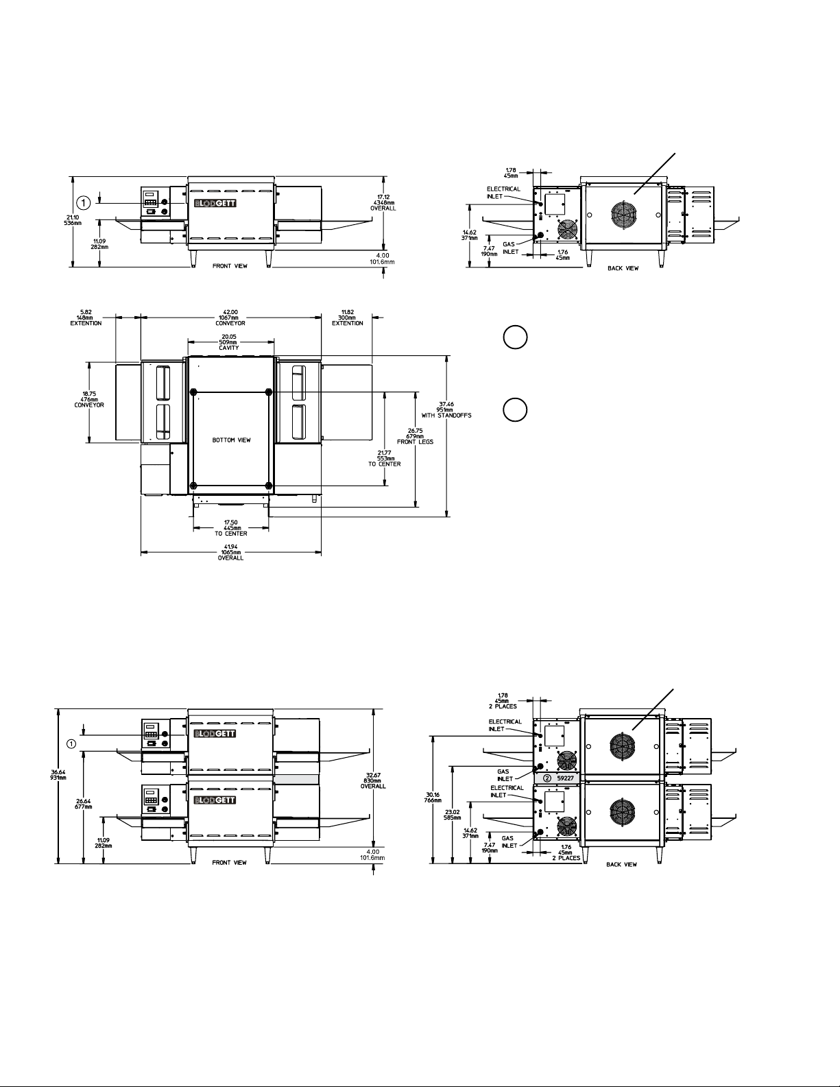
Figure 2-5.MODEL S1820G SINGLE OVEN DIMENSIONS
Blodgett
Front
Rear
1
The Opening Height is Adjustable
from 2-1/4 inch to 3-3/4 inch
maximum in 1/2 inch increments.
2
P/N 59227 is shown in its correct
installed position & must be
installed in the field on all double &
triple stack ovens.
Cooling Fan Blows In
Figure 2-6.MODEL S1820G DOUBLE OVEN DIMENSIONS
2
Cooling Fan Blows In
Page 6
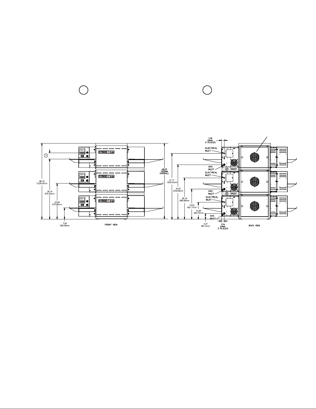
Figure 2.7. MODEL S1820G TRIPLE OVEN DIMENSIONS
1
The Opening Height is Adjustable
from 2-1/4 inch to 3-3/4 inch
maximum in 1/2 inch increments.
2
P/N 59227 is shown in its correct
installed position & must be
installed in the field on all double &
triple stack ovens.
Cooling Fan Blows In
3 Blodgett
Page 7
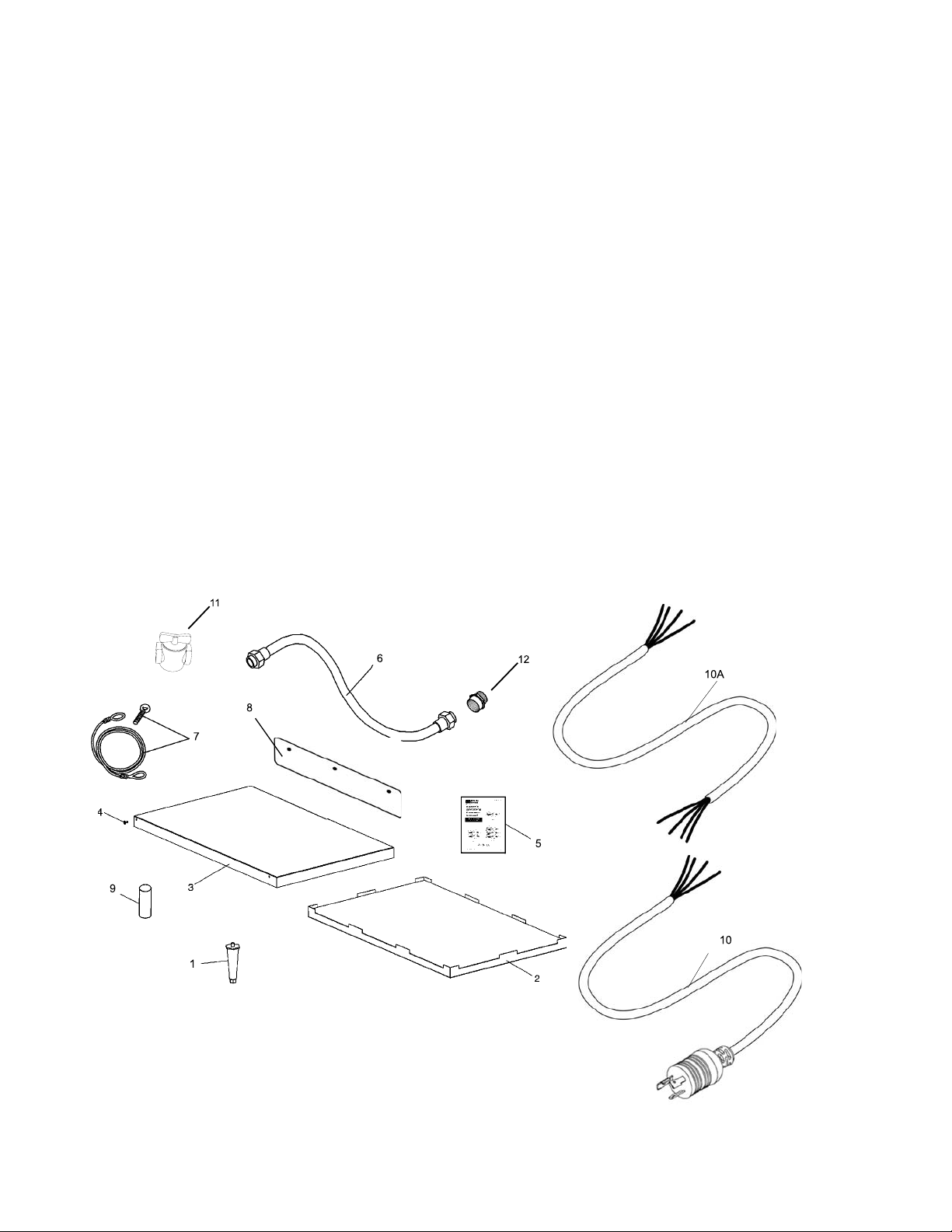
PARTS LIST FOR SERIES S1820G GAS OVEN
INSTALLATION KIT
Single, Double and Triple Stack Ovens
Single Double Triple
Kit #--> 59182 59183 59184
Item
NO. QTY QTY QTY PART NO. DESCRIPTION
1 .................... 4 ...................... 4 .................... - ....................... 3101908 Leg 4”
2.................... 1 ...................... 1 ................... 1.........................48395 Bottom Tray w/insulation
3.................... 1 ......................1 ................... 1.........................48396 Top cover
4.................... 4 ......................4 ................... 4.........................51387 Screw MSSLT Thread 8-32 x 1/2, 18-8
5.................... 1 ......................1 ................... 1.........................60213 Installation & Operation Manual - English
6 .................... 1 ...................... 2 ................... 3 .................... 22361-0001 Flexible gas hose 48”
7.................... 1 ......................1 ................... 1.................... 22450-0228 Restraint Cable
8.................... -....................... 1 ................... 2 .........................59227 Guard - Heat (must be installed in field)
9.................... -....................... -.................... 4........................ M3828 Pin - Alignment
10...................1 ......................2 ................... 3 .........................49975 Cord & plug (L6-20P)
10A.................. 1 ...................... 2 ................... 3 .........................49976 Cord only CE
11...................1 ......................2 ................... 3 .................... 23115-0009 Manual on/off gas valve
12 ...................1 ...................... 2 ................... 3 .........................31823 3/4” to 1/2” NPT reducer
4 Blodgett
Page 8

S1820G-SERIES GAS OVEN KEY PARTS
ITEM PART NO. DESCRIPTION QUANTITY
1 28041-0011 Contactor, DP 25A 208/240V 1
2 58390 Motor, Conveyor Drive 1
3 31651 Signal Amplifier Board 1
4 33812-5 Thermocouple, Type “J” Shielded 2.50” x 120” 3
5 59450 Valve, Module M420 (41647) 1
6 48455 Ignitor, Single Rod 1
7 50239 Ignition, Spark Module 24VAC 50/60Hz 1
8 50610 Switch, Air .13” W.C. 1
9 47321 Control, Combo 4-20MA (58504) 1
10 58323 Controller, Digital w/o Dip Switch 1
11 59142 Valve, Gas PS520 - Nat Gas 1
12 36451 Fan, Cooling 230VAC 295 CFM-Blows In 1
13 50240 Ignition Cable 25” 1
14 52244 Main Blower 2
15 33983 High Limit Module 1
2
5
13
1
8
3
9
15
6
10
7
11
12
4
14
5 Blodgett
Page 9

S1820 STD
6 Blodgett
Page 10

S1820G-SERIES PARTS MANUAL
Triple stack ovens.
field on Double and
Must be installed in the
Heat Guard
Front View Of Oven
Serial Tag Location
7 Blodgett
Page 11

S1820G-SERIES PARTS MANUAL
Parts For Front View Of Oven
includes item 5 eyebrow
pper LH End Plug Assembly,
includes item 6 eyebrow
nd Plug Mounting Bracket Assembly .875”
ut, Wing-Plastic 1/4-20
eg, 4” ADJ FT (NPS)
Triple stack ovens
1 1 48382 U
2 1 48387 Lower LH End Plug Assembly
3 1 48408 Lower RH End Plug Assembly
4 1 48412 Upper RH End Plug Assembly,
5 1 48378 Eyebrow, Upper LH End Plug Assembly
6 1 48410 Eyebrow, Upper RH End Plug Assembly
7 4 51398 E
8 8 21296-0005 Screw, Hex Head, WSHHD 12-14x3/4 SS BSD
9 6 36452 N
10 4 3101908 L
11 1 48395 Bottom Tray Assembly
12 1 48396 Cover, Top
13 4 51387 Scr, MS, SLT THRD 8-32x1/2” 18-8
ITEM QTY PART NO. DESCRIPTION
8 Blodgett
14 1 49975 Cordset, L6-20P
15 1 57399 Nameplate, Blodgett
16 1 52256 Cover, Motor
17 4 M3828 Alignment Pin (Triple Stack)
14A 1 49976 Cord only (CE Models)
18 1 or 2 59227 Guard, Heat (must be installed in the field on Double and
Page 12

S1820G-SERIES PARTS MANUAL
View of Left HandElectricalCompartment
1A
1
9 Blodgett
Page 13

Parts For Left Hand Electrical Compartment
10 Blodgett
1 1 46521 Kit Conveyor Switch (Contains (1) 44697, (1) 44696)
ITEM QTY PART NO. DESCRIPTION
4 1 58323 Conveyor Speed control w/Digital Speed Display
5 1 37503 Digital Speed Control (Display Only)
6 1 47321 Temperature Control (58504)
7 1 28041-0011 Contactor, 208/240V-25A
8 1 31504 Transformer, 230V(P)/120(S), 200VA
1A 1 46522 Kit Heat/Blower Switch (Contains 2-44697 & 1-44696)
9 1 28021-0047 Switch, Interlock, 10A, NO 2 Pole
10 1 33983 Control, Electric, Hi-Limit, 240V
11 1 58390 Motor, Conveyor Drive With 2-Pole Magnet
11a 1 39002 Magnet 2-Pole
11b 1 310-0017 Adhesive
12 1 38185 Sensor-Conveyor Pick-up
13 1 35145 Switch, Push-button, Molveno, 250V
14 2 45036 Breaker, Circuit 240V, 3A
11d 1 58484 Kit, 2 brushes & 2 caps
15 1 48635 Breaker, Circuit 240V, 0.3A
16 1 or 2 33812-5 Thermocouple, Type “J”, Shielded, 2.5”x 20”
Page 14

S1820G -SERIES PARTS MANUAL
Cooling Fan Blows In
Gas Input
As viewed from the rear
blower motor spins CCW
Must be Installed in the Field
Rear View Of BlowerCompartment
Must be Installed in the Field
11 Blodgett
Page 15

S1820G-SERIES PARTS MANUAL
Parts For Rear View Blower Compartment
1 1 28021-0061 Switch, Momentary-10A, NO 2 Pole
ITEM QTY PART NO. DESCRIPTION
2 2 30927 Bumper, Window
an, Cooling, 230V AC, 295 CFM -Blows In
3 1 36451 F
4 2 52244 Motor, Blower, CW, 208/230V 50/60 Hz With Blower Wheel
5 2 57258 Plate, Air Vent
6 4 7007413 SCR, Shoulder 10-32x3/4 18-8
7 1 31497 Guard-Cooling Fan
8 1 27470-0004 Guard - Right Hand Control Compartment
12 Blodgett
Page 16

Must Be Installed In the Field
Heat Guard
S1820G-SERIES PARTS MANUAL
View Of Right Hand Of Electrical Compartment
13 Blodgett
Page 17

16A 1 59416 Kit, Convert gas valve to NAT
16B 1 59415 Kit, Convert gas valve to LP
Parts For Right Hand Electrical Compartment
17 1 31651 Amplifier Board
18 1 50239 Ignition Module
19 1 50240 Ignition Cable 25" (635mm)
20 1 59450 Modulating Gas Valve (41647)
21 1 50794 Ignition Relay
22 2 44888 Fitting, Compression
23A 1 59145 Orifice Bypass, Natural #49 .073”
24 1 44390 Terminal Block
23B 1 49948 Orifice Bypass, Propane 0.0520" #55
25A 1 59146 LP to Nat Kit (includes 16A, 5A, 23A)
26 1 59018 Bypass Tube
27 1 59127 Pipe Assembly Clamp
28 1 59227 Heat Guard
25B 1 59147 Nat to LP Kit (includes 16B, 5B, 23B)
29 1 37000-0781 Pipe Clamp
1 1 or 2 33812-5 Thermocouple, Type “J” Shielded 2.5” x 120”
2 1 28021-0047 Switch, Interlock
3 2 30002 Tap, Plug
4 1 59023 Manifold
ITEM QTY PART NO. DESCRIPTION
5A 2 59144 Main Orifice Natural #45 .082”
6 1 59125 Cover Plate, Inshot Burner Housing
5B 2 59143 Main Orifice Propane 0.057” (1.45mm)
7 1 59006 Assembly, Burner Tubes
8 1 48455 Ignitor
9 2 59002 Burner, Inshot
10 1 50610 Air Switch
11 1 33813 RFI Filter
12 1 27470-0004 Fan Guard
13 1 41872 Transformer 240V Pri, 24V Sec 25VA
14 1 32108 Transformer 240V Pri, 24V Sec 65VA
15 1 45644 Circuit Breaker, 1 Amp
16 1 59142 Combo Gas Valve - Natural Gas
14 Blodgett
Page 18

S1820G-SERIES PARTS MANUAL
View of Conveyor Parts
15 Blodgett
Page 19

Rulon
eldment
haft, Drive
procket, Wire Belt
elt, Wire, Stainless Steel, 18”x87-1/2”
it, Master Link Front, Middle, Rear
Parts For Conveyor
1 1 59275 W
2 2 M4817 Bearing,
3 1 M4815 S
4 1 59271 Shaft, Idler
5 10 M4818 S
6 1 59307 B
ITEM QTY PART NO. DESCRIPTION
7 1 58391 K
10 1 55567 Assy, Chain High Speed w/Master Link
10a 1 310-1212 Master Link Only
11 1 55217 Sprocket, chain #25-20T-1/2” Conveyor Shaft
12 1 45349 Sprocket, 25B25 w/5/16” Bore - Drive Shaft (Motor)
13a 1 39002 Magnet 2-Pole
13 1 58390 Motor, Conveyor Drive w/2 Pole Magnet
13c 1 58484 Kit, 2 Brushes & 2 Caps
13b 1 310-0017 Adhesive
14 1 38185 Sensor-Conveyor Pick-up
15 1 59280 Extension, Conveyor - 6”
16 1 59272 Extension, Conveyor - 12”
17 2 51409 Pan, Crumb Vented - Shipped As Standard
18 2 59276 Screw Adjustment
19 2 59264 Bushing, Rulon - Idler
20 1 59267 Idler Guide - Back
21 1 59270 Idler Guide - Front
16 Blodgett
Page 20

S1820G-SERIES PARTS MANUAL
View of Cart Parts
17 Blodgett
Page 21

S1820G-SERIES PARTS MANUAL
Parts For Oven Cart
1 52237 Wldmt,Base Cart Panel
1 52238 Panel, Cover Cart
#52241 #54596
Single/Double Triple
1 1
ITEM QTY QTY PART NO. DESCRIPTION
2 1
0 52240 Wldmt, Lower Shelf Cart Panel
6 16 A3682 Washer, Lock 5/16”
3 2
4 1
0 F706A8805 Washer, FLat Rivet Burr 1/4” NP
6 16 B10012 Nut, Hex 5/16”-18 ZP
5 1
6 4
0 M10435 Scr, MS PH PANHD 1/4”-20 x 2-14”
6 16 M0226 Washer, Flat 5/16”
7 1
8 4
4 54657 Leg 5” - Triple Only
0 M2585 Leg 18” Single and Double
9a 4
9b 0
10a 2 2 15688 Caster w/o Brake
10b 2 2 15687 Caster w/Brake
11 4 4 M3828 Pin - Alignment
12 4 0 M7958 Nut, Nylon Insert 1/4-20
18 Blodgett
Page 22

S1820G
19
Blodgett
Page 23

20 Blodgett
Page 24

WARNING
Improper installation, adjustment, alteration, service or
maintenance can cause property damage, injury or death. Read
the installation, operating and maintenance instructions
thoroughly before installing or servicing this equipment.
NOTICE
During the warranty period. ALL parts replacement and servicing should be
performed by your Blodgett Authorized Service Agent. Service that is
performed by parties other than your Blodgett Authorized Service Agent
may void your warranty.
NOTICE
Using any parts other than genuine Blodgett factory manufactured parts
relieves the manufacturer of all warranty and liabilities.
NOTICE
Blodgett reserves the right to change specifications at any time.
Blodgett is proud to support the Commercial Food
Equipment Service Association (CFESA). We
recognize and applaud CFESA’s ongoing efforts to
improve the quality of technical service in the industry.
Blodgett Conveyor Oven • 1400 Toastmaster Drive • Elgin, IL 60120 • USA • (847) 741-3300 • FAX (847) 741-4406
www.blodgett.com
 Loading...