

Page 1
S1820
CONVEYOR OVEN
REPLACEMENT PARTS MANUAL
(with WIRING DIAGRAMS)
SPL081505-PF-BD
August 15, 2005
EFFECTIVE with SERIAL #351410405 and AFTER
Serial # Code
First 4 digits - order of production
Fifth digit - model specific
Sixth and Seventh digit - month of production
Eighth and Ninth digit - year of production
Table of Contents: Page 2
BLODGETT CONVEYOR OVEN, 1400 Toastmaster Drive, Elgin, IL 60120
Telephone: 847-741-3300 • Fax Number 847-741-4406
www.blodgett.com
email: techsupport@middleby.com
Page 2

Table of Contents
Spec Sheet ......................................................................................................................3
Oven and Electrical Specifications ................................................................................... 5
Installation Kit ..................................................................................................................6
Key Parts ......................................................................................................................... 7
Front View of Oven...........................................................................................................8
Parts for Front View of Oven ............................................................................................ 9
Right-hand View of Electrical Compartment ................................................................... 10
Parts for Right-hand View of Electrical Compartment..................................................... 11
Rear-view of Blower Compartment ................................................................................ 12
Parts for Rear-view of Blower Compartment .................................................................. 13
View of Left-hand Electrical Compartment ..................................................................... 14
Parts for Left-hand Electrical Compartment ................................................................... 15
View of Conveyor Parts ................................................................................................. 16
Parts for Conveyor ......................................................................................................... 17
NOTES...........................................................................................................................18
Wiring Diagrams (Electrical Schematics)
208/240 volt single phase domestic USA 3 thermocouples-48713 H .............................. 19
380/480 volt single phase domestic USA 3 thermocouples-52445 H .............................. 20
230/240 volt single phase CE 3 thermocouples-52446 H ................................................ 21
380/400 volt single phase CE 3 thermocouples-54661 H ................................................ 22
208/240 volt three phase domestic USA 3 thermocouples-55235 D................................ 23
380/480 volt three phase domestic USA 3 thermocouples-57229 D................................ 24
380/400 volt three phase CE 3 thermocouples-57230 D ................................................. 25
380/400 volt three phase CE HighLeg 3 thermocouples-58158 D ................................... 26
208/240 volt three phase domestic USA HighLeg 3 thermocouples-58227 C .................. 27
380/480 volt three phase domestic USA HighLeg 3 thermocouples-58228 C .................. 28
Standard Air Finger Configuration (Old style September 2005 and before) ..................... 29
Standard Air Finger Configuration (New style October 2005 and after)........................... 30
2
Page 3

BLODGETT CONVEYOR OVEN
www.blodgett.com
1400 Toastmaster Drive, Elgin, IL 60120 • Phone: 847-741-3300 • Fax Number 847-741-4406
3
Page 4
38.00
(965)
Printed in U.S.A.
BLODGETT CONVEYOR OVEN
www.blodgett.com
1400 Toastmaster Drive, Elgin, IL 60120 • Phone: 847-741-3300 • Fax Number 847-741-4406
NOTE: FOR COMMERCIAL USE ONLY
4
P/N M10989 Rev C (8/05)
Page 5

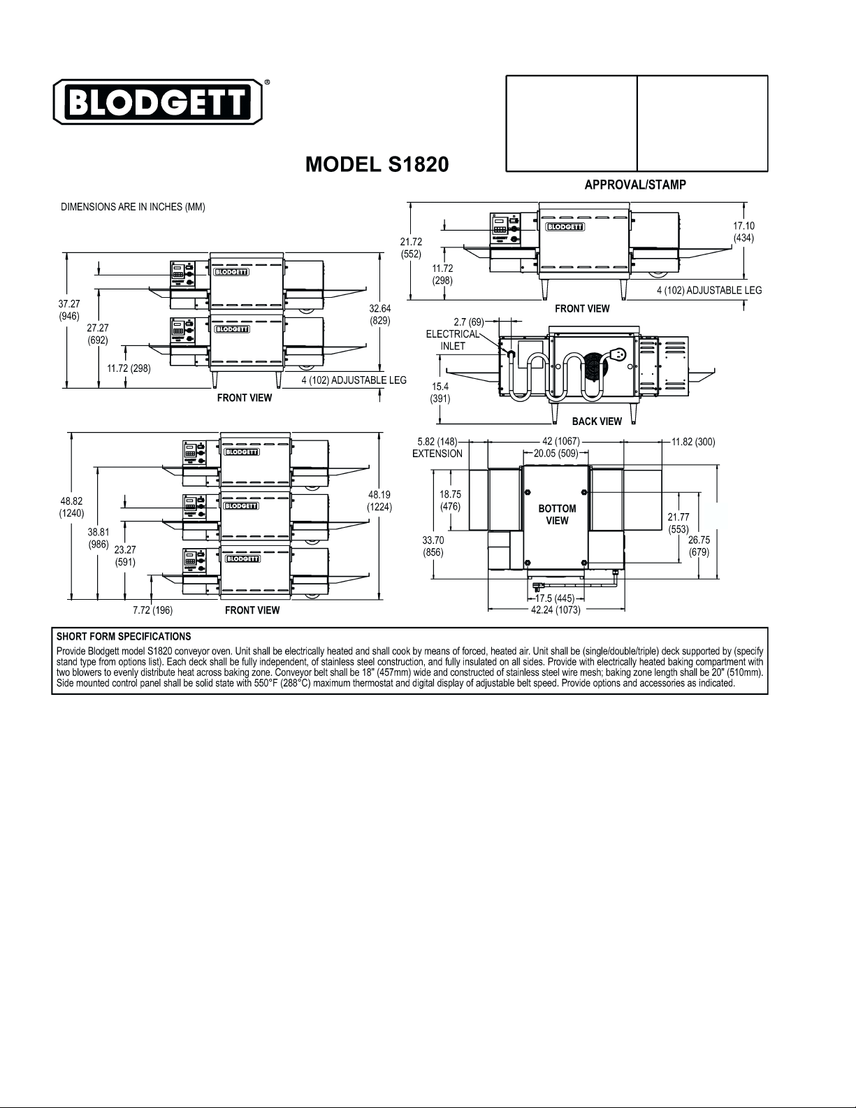
S1820 OVEN SPECIFICATIONS
Conveyor Belt Width 18.00″ (457mm)
Heating Zone Length 20.00″ (5098mm)
Baking Area Square Feet 2.5 sq. ft. (0.23 sq. m.)
Overall Dimension
Standard Single Oven w/Legs 42.00″ (1067mm) L ×
Overall Dimension
Double Oven 42.00″ (1067mm) L ×
Overall Dimension
Triple Oven 42.00″ (1067mm) L x
Weight of Single Oven 250 lb (93.3kg)
Shipping Weight 325 lb (121.3kg)
Shipping Cube 22.1 ft3 (0.62 m3)
Operating Range 8.3 kW/hr
Maximum Operating Temperature 550°F (287°C)
Warm-up Time 20 min.
Bake Time Range 1-10 minutes
38.00″ (965mm) W ×
21.72″ (786mm) H ×
38.00″ (965mm) W ×
37.27″ (947mm) H x
38.00″ (965mm) W ×
52.82″ (1342mm) H ×
S1820 ELECTRICAL SPECIFICATIONS
Main Blower & Control Circuit Phase Frequency Amperage Poles Wires
Elements Voltage Voltage Draw
208-240V 208-240V 1 Ph 50/60 Hz 39.9 Amp 2 Pole 3 Wire
HEATER AMPERAGE
Voltage kW Amp
208 8.3 39.9
230 7.6 33.0
240 8.3 34.6
380V Export 208-240V 1 Ph 50/60 Hz 21.8 Amp 3 Pole 4 Wire
HEATER AMPERAGE
Voltage kW Amp
380 8.3 21.8
400 9.2 23.0
480V 208-240V 1 Ph 50/60 Hz 17.3 Amp 3 Pole 4 Wire
HEATER AMPERAGE
Voltage kW Amp
480 8.3 17.3
(2 hot, 1 grd)
(2 hot, 1neut, 1 grd)
(2 hot, 1neut, 1 grd)
5
Page 6
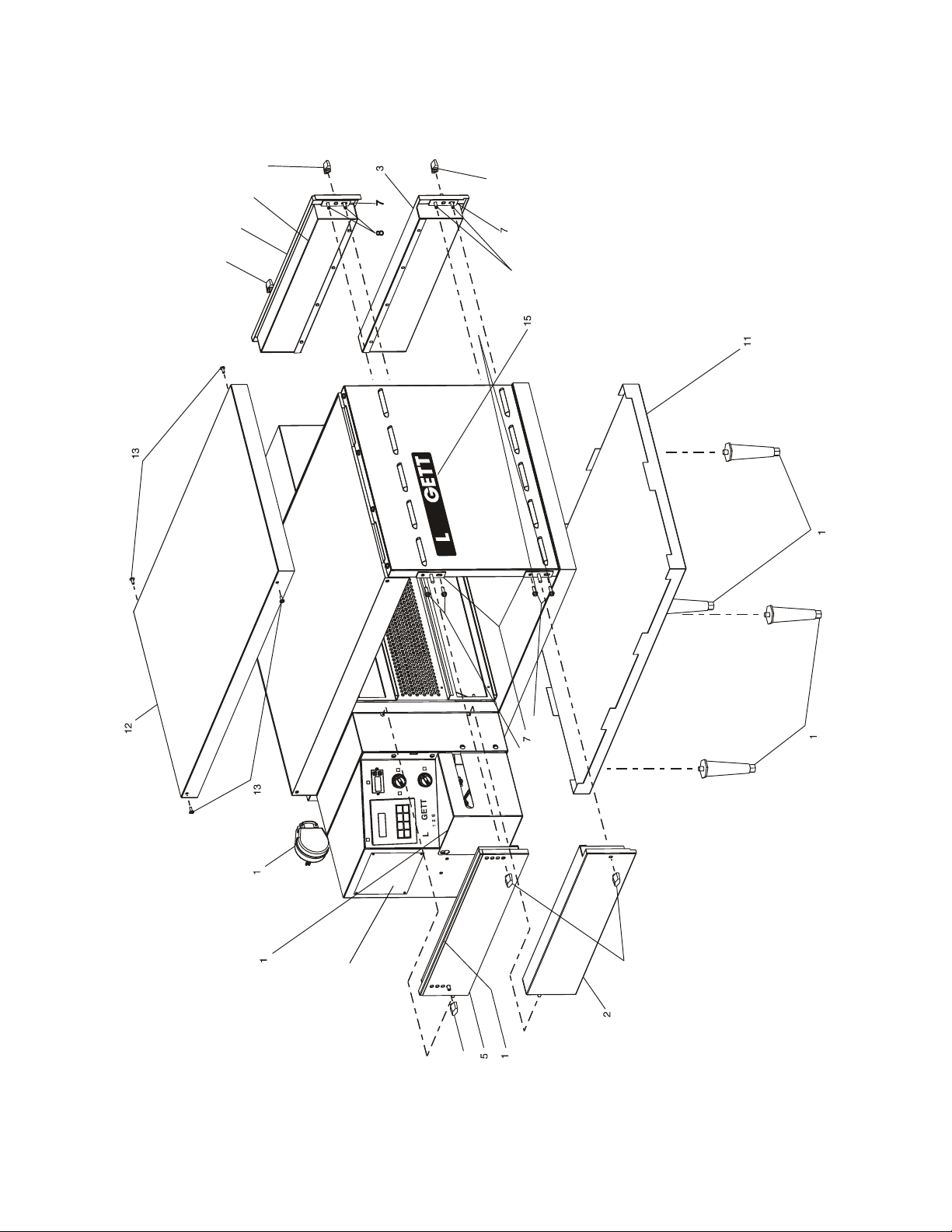
PARTS LIST FOR 1820S ELECTRIC OVEN
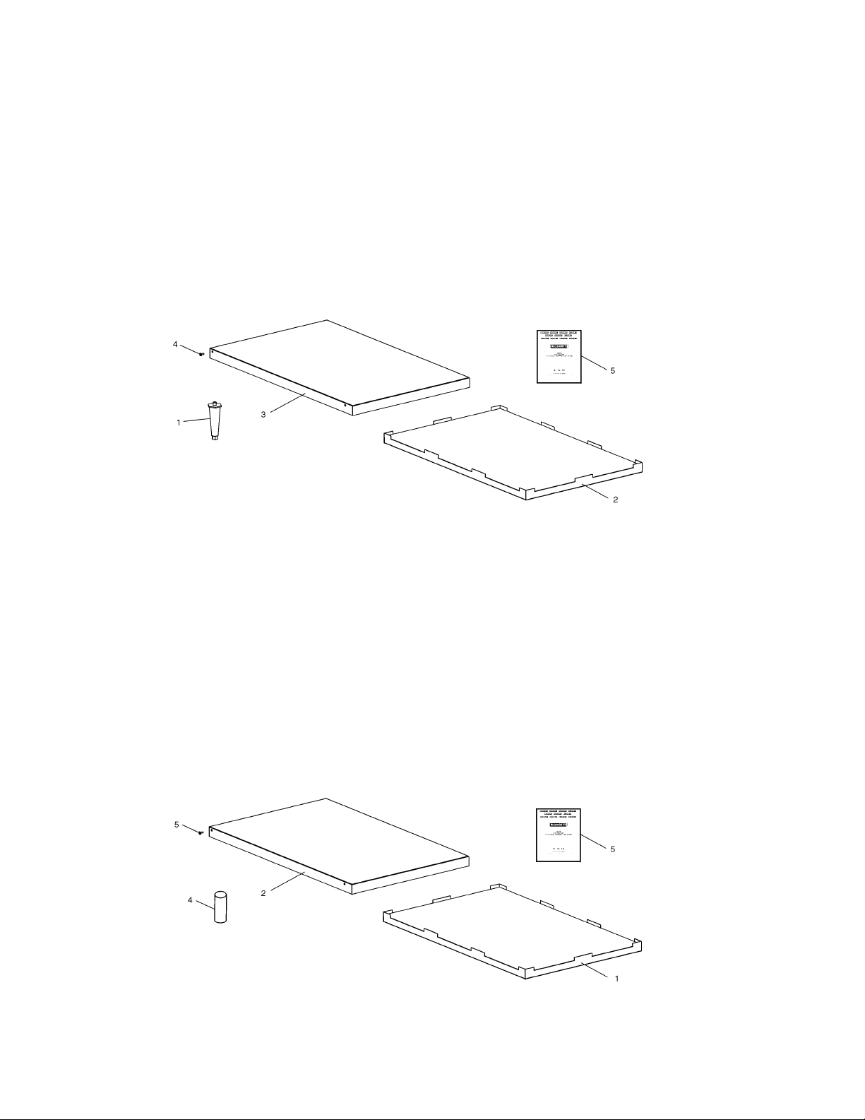
INSTALLATION KIT
Single and Double Stack Ovens
P/N 54659
ITEM
NO. QTY PART NO. DESCRIPTION
1 4 3101908 LEG 4″ AD FT
2 1 48395 BOTTOM TRAY w/INSULATION
3 1 48396 TOP COVER
4 4 51387 SCREW MSSLT THREAD 8-32 × 1/2, 18-8
5 1 55310 OWNER'S OPERATING & INSTALLATION MANUAL
PARTS LIST FOR S1820 ELECTRIC OVEN
INSTALLATION KIT
Triple Stack Oven
P/N 54660
ITEM
NO. QTY PART NO. DESCRIPTION
1 1 48395 BOTTOM TRAY w/INSULATION
2 1 48396 TOP COVER
3 4 51387 SCREW MSSLT THREAD 8-32 × 1/2, 18-8
4 4 M3828 PIN, ALIGNMENT
5 1 55310 OWNER'S OPERATING & INSTALLATION MANUAL
Figure 1. S1820 Electric Oven Installation Parts
6
Page 7
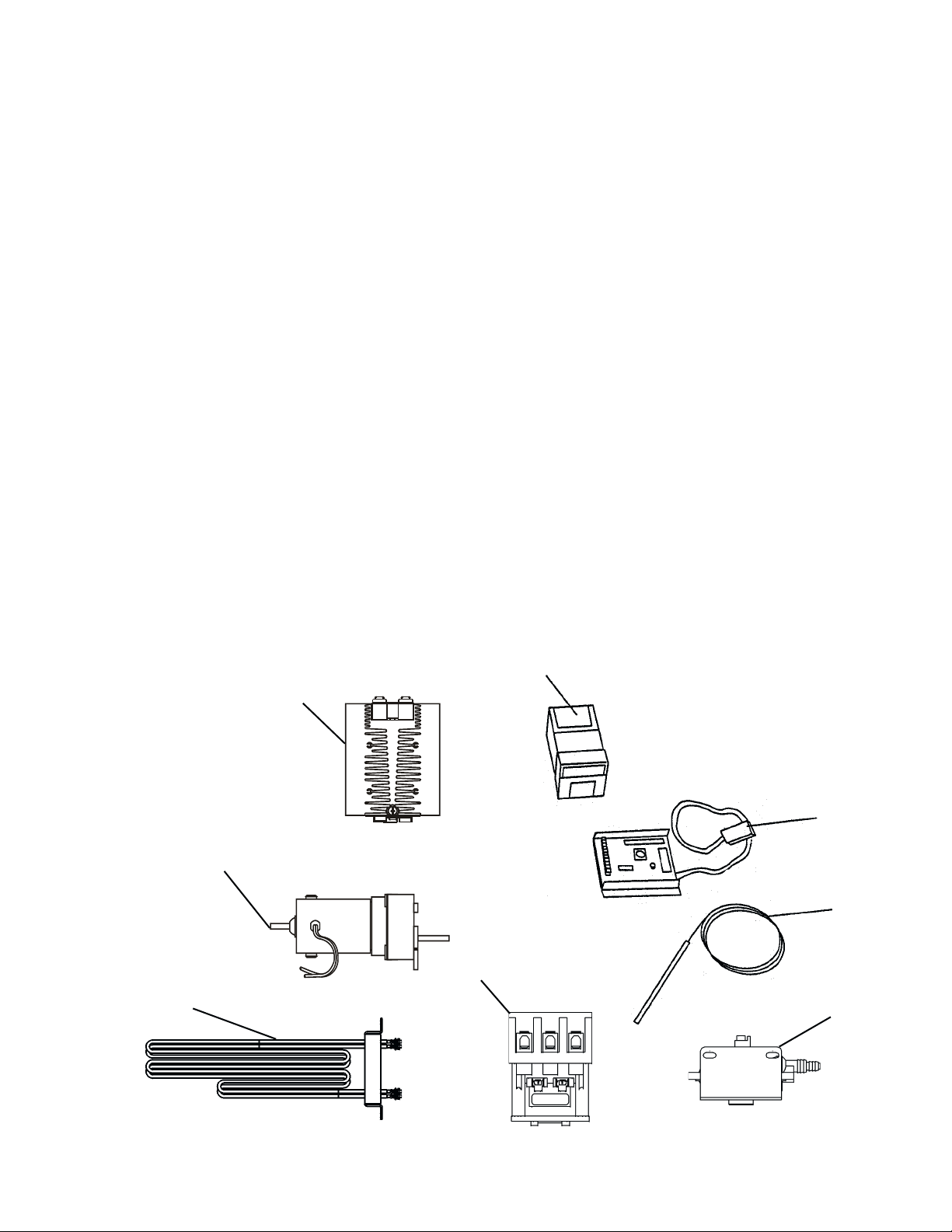
KEY SPARE PARTS KIT
An oven can be purchased with a Key Spare Parts Kit
(Figure 2). (The kit can be purchased when the oven is
ordered, or later, from a Blodgett Authorized Parts
Distributor). The kit contains many of the crucial parts that
S1820 ELECTRIC OVEN KEY SPARE PARTS KIT (Figure 2)
ITEM PART NO. ENGLISH DESCRIPTION QUANTITY
1 47321 Kit, Temperature Control On/Off Pid 1
2 48636 Relay, 100A 1
3 58390 Conveyor Drive Motor Kit 1
4 37337 Conveyor Speed Control 1
5 33812-5 Thermocouple(s)* (3 used) 1
6 50715 Heater Element, 208V 1
6 51017 Heater Element, 240V 1
6 51958 Heater Element, 380V 1
6 51961 Heater Element, 480V 1
7 57408 Contactor 1
8 50610 Air Switch 1
can reduce serious downtime and loss of production, if a
failure occurs.
Replacement parts for this kit can be purchased from your
Blodgett Authorized Parts Distributor.
* The proper location for the thermocouple is as follows: 1) A temperature sensing
thermocouple is located on the entrance end and exit end of the unit on the bottom,
2) High limit is located on the exit end of the unit on the top as standard (on a left to right
direction), 3) High limit on the S1820 is 550 degree's.
1
2
3
7
6
4
5
8
Figure 2.
7
Page 8
Front View of Oven
Serial Tag Location
8
Page 9

Parts for Front View of Oven
1 1 48382 UPPER LH END PLUG ASSEMBLY, INCLUDES PART # 48378, ITEM 5
2 1 48387 LOWER LH END PLUG ASSEMBLY
3 1 48408 LOWER RH END PLUG ASSEMBLY
4 1 48412 UPPER RH END PLUG ASSEMBLY, INCLUDES PART # 48410, ITEM 6
5 1 48378 EYEBROW, UPPER LH END PLUG ASSEMBLY
6 1 48410 EYEBROW, UPPER RH END PLUG ASSEMBLY
ITEM QTY PART NO. DESCRIPTION
7 4 51398 END PLUG MOUNTING BRACKET ASSEMBLY .875
8 8 21296-0005 SCREW, HEX HEAD, WSHHD 12-14X3/4 SS BSD
9 6 36452 NUT, WING-PLASTIC 1/4-20
10 4 3101908 LEG, 4” ADJ FT (NPS)
11 1 48395 BOTTOM TRAY ASSEMBLY
12 1 48396 COVER, TOP
13 4 51387 SCR, MS, SLT TRHD 8-32X1/2 18-8
14 1 M10434 CORDSET, 50 AMP 250V 2P 3W
15 1 57399 NAMEPLATE, BLODGETT SM
16 1 52256 COVER, CHAIN
9
Page 10

8, 9 NOT SHOWN – AIR TUBE
Right-hand View of Electrical Compartment
1
10
Page 11

Parts for Right-hand View of Electrical Compartment
1 1 or 2 33812-5 THERMOCOUPLE, TYPE “J”, SHIELDED 2.50X120”
2 1 28021-0047 SWITCH, INTERLOCK, 10A, NO2P
3 1 51402 RELAY, HEATSINK 480VAC 100A
4 1 51961 ELEMENT, HEATING, 480V
4 1 51958 ELEMENT, HEATING 380V
4 1 51017 ELEMENT, HEATING 240V
4 1 50715 ELEMENT, HEATING, 208V
5 1 57408 CONTACTOR, 208/240V, 65A, 50/60 Hz
6 1 300-3946 BLOCK, POWER DIST 3POLES
7 1 M10434 CORDSET, 50 AMP, 250V, 2P 3W
8 1 50610 SWITCH, AIR 0.16 IN. WC
ITEM QTY PART NO. DESCRIPTION
9 3 FT. 22450-0297 TUBING, SILICONE RUBBER, 27” SOLD BY THE FOOT
11
Page 12

10 NOT SHOWN – AIR TUBE
7 FAN GUARD – NOT SHOWN
8
9
Rear-view of Blower Compartment – As viewed from Rear – Blower Motor Spins CCW
12
Page 13

Parts for Rear-view of Blower Compartment
1 1 28021-0061 SWITCH, MOMENTARY-1OA, NO 2 POLE
2 2 30927 BUMPER, WINDOW
3 1 51399 FAN, COOLING, 230V AC, 295 CFM
4 2 52244 MOTOR, BLOWER, CW, 208/230 50/60HZ
5 2 57258 PLATE, AIR VENT
6 4 7007413 SCR, SHOULDER 10-32X, 34 18-8
7 1 31497 GUARD, COOLING FAN
8 1 57474 1/4” ALUMINUM TUBE, AIR SWITCH
9 3 57476 CLAMP, AIR TUBE
iTEM QTY PART NO. DESCRIPTION
10 3 FT. 22450-0297 TUBING, SILICONE RUBBER, 27” SOLD BY THE FOOT
13
Page 14

View of Left-hand Electrical Compartment
14
Page 15

Parts for Left-hand Electrical Compartment
1 1 46521 KIT-SWITCH (CONVEYOR) CONTAINS (1) 44697 & (1) 44696)
2 1 46522 KIT-SWITCH (BLOWER/HEAT) CONTAINS (2) 44697 & (1) 44696)
3 2 44696 SELECTOR SWITCH
4 1 37337 CONVEYOR SPEED CONTROL W/DIGITAL SPEED DISPLAY
5 1 37503 DIGITAL SPEED CONTROL (DISPLAY ONLY)
6 1 47321 CONTROL, COMBO 4-20MA BURST
7 1 28041-0011 CONTACTOR, 208/240V
8 1 31504 TRANSFORMER, 230V(P)/120V(S), 200VA
9 1 28021-0047 SWITCH, INTLCK, 1OA, NO2P
10 1 33983 CONTROL, ELECTRIC, HI-LIMIT, 24OV
ITEM QTY PART NO. DESCRIPTION
11 1 58390 MOTOR, CONVEYOR DRIVE
11a 1 39002 MAGNET 2-POLE
12 1 38185 KIT, CONVEYOR PICK-UP
13 1 35145 SWITCH, PUSHBUTTON, MOLVENO, 250V
11b 1 310-0017 ADHESIVE
11c 1 300-2757 CONVEYOR DRIVE MOTOR-ONLY
11d 1 58484 KIT, 2 BRUSHES & 2 CAPS
11e 2 30153 BRUSH, SOLD INDIVIDUALLY, QTY 2 REQUIRED
14 2 45036 BREAKER, CIRCUIT 240V, 3A
15
15 1 48635 BREAKER, CIRCUIT 240V, 0.3A
16 1 or 2 33812-5 THERMOCOUPLE, TYPE “J”, SHIELDED, 2.50X120”
Page 16

View of Conveyor Parts
16
Page 17

Parts for Conveyor
1 1 48471 WELDMENT
2 4 M4817 BEARING, RULON
3 1 M4815 SHAFT, DRIVE
ITEM OTY PART NO. DESCRIPTION
4 1 51408 SHAFT, IDLER
5 10 M4818 SPROCKET, WIRE BELT
6 1 M7471 BELT, WIRE, STN STL
7 1 58391 LINK, MASTER LEFT 1/2P-18”, KIT, MASTER LEFT, CENTER, RIGHT
10 1 55567 ASSY, CHAIN HIGH SPEED, w/ MASTER LINK
11 1 55217 SPROCKET, CHAIN #25-20T-1/2
10a 1 310-1212 MASTER LINK, CHAIN
12 1 45349 SPROCKET, 25B25 w/ 5 / 16 BORE
13 1 58390 MOTOR, CONVEYOR DRIVE KIT
13a 1 39002 MAGNET 2-POLE
13b 1 310-0017 ADHESIVE
13c 1 300-2757 CONVEYOR DRIVE MOTOR ONLY
13d 1 58484 KIT, 2 BRUSHES & 2 CAPS
14 1 38185 SENSOR, CONVEYOR PICK-UP
13e 2 30153 BRUSH, SOLD INDIVIDUALLY, QTY 2 REQUIRED
15 1 51297 EXTENSION, CONVEYOR, 6”
16 1 51296 EXTENSION, CONVEYOR, 12”
17 2 48469 PAN, CRUMB
18 2 51409 PAN, CRUMB VENTED, SUPPLIED AS STANDARD
17
Page 18

NOTES
18
Page 19

48713 Rev. H
19
Wiring Diagram, E208-240V 50/60/1, S1820
Page 20

52445 Rev. H
20
Wiring Diagram, E380-480V 50/60/1, S1820
Page 21

52446 Rev. H
21
Wiring Diagram, E230-240V CE S1820
Page 22

54661 Rev. H
22
Wiring Diagram, E380-400V CE S1820
Page 23

55235 Rev. D
23
Wiring Diagram, 208/240 volt three phase domestic USA 3 thermocouples
Page 24

57229 Rev. D
24
Wiring Diagram, 380/480 volt three phase domestic USA 3 thermocouples
Page 25

57230 Rev. D
25
Wiring Diagram, 380/400 volt three phase CE 3 thermocouples
Page 26

58158 Rev. D
26
Wiring Diagram, 380/400 volt three phase CE HighLeg 3 thermocouples
Page 27

58227 Rev. C
27
Wiring Diagram, 208/240 volt three phase domestic USA HighLeg 3 thermocouples
Page 28

58228 Rev. C
28
Wiring Diagram, 380/480 volt three phase domestic USA HighLeg 3 thermocouples
Page 29

A = 51989 PLATE, OTR L16GN W/2 (12) 2 ROWS
47758 PLATE, INNER
47765 WLDMT, MANIFOLD L16 GN
B = 51990 PLATE, OTR L16GN W/2 (3) 3 (5) 3 ROWS
47758 PLATE, INNER
47765 WLDMT, MANIFOLD L16 GN
Standard Air Finger Configuration (Old style September 2005 and before)
52249 Rev. F
29
Page 30

A = 51357 PLATE, OTR L5GN W/7 HOLES
51027 PLATE, INR L5 GN COL/ALUZ
51986 WLDMT, MANIFOLD L5GN PRTL BFL
B = 51356 PLATE, OTR L5GN W/2 ROWS
51027 PLATE, PLATE, INR L5 GN COL/ALUZ
51986 WLDMT, MANIFOLD L5GN PRTL BFL
C = 50682 PLATE, BLANK FULL
Standard Air Finger Configuration (New style October 2005 and after)
51988 Rev. D
30
Page 31

NOTES
31
Page 32

32
 Loading...