

Page 1

MT3255E
CONVEYOR OVENS
FOR GENERAL EXPORT
INSTALLATION -- OPERATION -- MAINTENANCE
BLODGETT OVEN COMPANY
www.blodgettcorp.com
50 Lakeside Avenue, Box 586, Burlington, Vermont 05402 USA Telephone (800) 331-5842, (802) 860-3700 Fax: (802)864-0183
PN M9126 Rev B (6/01)
E 2000 --- G.S. Blodgett Corporation
Page 2

IMPORTANT
WARNING: IMPROPER INSTALLATION, ADJUSTMENT,
ALTERATION, SERVICE OR MAINTENANCE CAN CAUSE
PROPERTY DAMAGE, INJURY OR DEATH. READ THE INSTALLATION, OPERATING AND MAINTENANCE INSTRUCTIONS THOROUGHLY BEFORE INSTALLING OR
SERVICING THIS EQUIPMENT
FORYOURSAFETY
Do not store or use gasoline or other flammable vapors or
liquids in the vicinity of this or any other appliance.
The information contained in this manual is important for the proper
installation, use, and maintenance of this oven. Adherence to these
procedures and instructions will result in satisfactory baking results
and long, trouble free service. Please read this manual carefully and
retain it for future reference.
Errors: Descriptive, typographic or pictorial errors are subject to correc-
tion. Specifications are subject to change without notice.
Page 3

BLODGETT - THE REPUTATION YOU CAN COUNT ON
For nearly a century and a half, The Blodgett Oven Company
has been building ovensand nothing but ovens. We’ve set the
industry’s quality standard for all kinds of ovens for every foodservice operation regardless of size, application or budget. In
fact, no one in the foodservice industry has more oven engineering experience than Blodgett, and no one offers more
models, sizes, and oven applications than Blodgett; gas and
electric, full-size, half-size, countertop and deck, convection,
Cook’n Hold, Combi-Ovens and the industry’s highest quality
Pizza Oven line. For more information on the full line of
Blodgett ovens contact your Blodgett representative.
Page 4

Your Service Agency’s Address:
Model:
Serial Number:
Your oven w a s installed by:
Your oven’s installation was checked by:
Page 5

Tab l e o f C o n t e n t s
Introduction
Oven Description and Specifications 2................................
Oven Components 3...............................................
Installation
Delivery and Inspection 4...........................................
Oven Location 5...................................................
Oven Assembly 6..................................................
Oven Supports and Casters 6....................................
Return Air Diverters 6............................................
Nozzles 7......................................................
Conveyor Belt Support 7.........................................
Conveyor Belt 8................................................
End Plugs 10....................................................
Crumb Pans 10..................................................
Electrical Connection 11.............................................
Operation
Safety Information 12................................................
Standard Controls 13................................................
Oven Adjustments for Cooking 14.....................................
Maintenance
Cleaning 16........................................................
Troubleshooting Guide 18............................................
Page 6
Introduction
Oven Description and Specifications
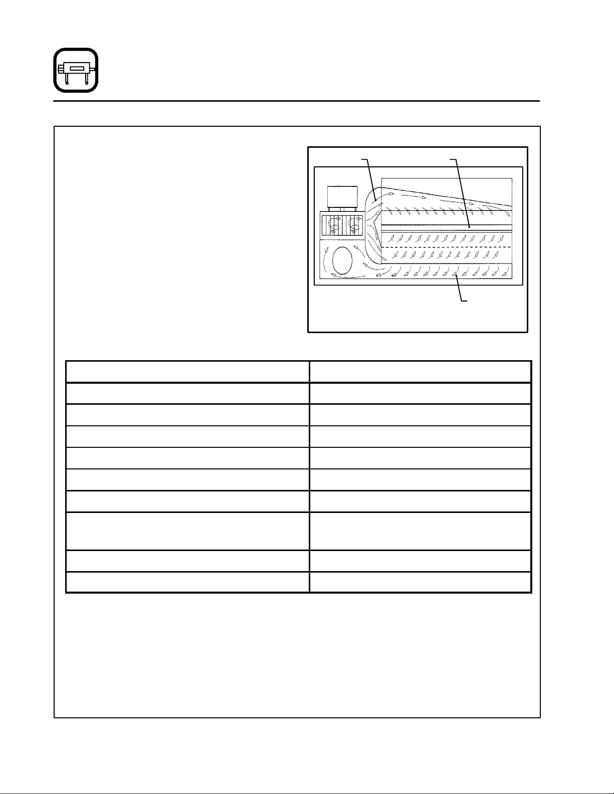
Cooking in a conveyor oven differs from cooking
in a conventional deck or range oven since heated
air is constantly recirculated over the product by
a fan in an enclosed chamber. The moving air continually strips away the layer of cool air surrounding the product, quickly allowing the heat to penetrate. The result is a high quality product, cooked
at a lower temperature in a shorter amount of time.
Blodgett conveyor ovens represent the latest advancement in energy efficiency, reliability, and
ease of operation. Heat normally lost, is recirculated within the cooking chamber before being
vented from the oven: resulting in substantial reductions in energy consumption, a cooler kitchen
environment and enhanced oven performance.
SPECIFICATIONS
Belt Width 32” (81 cm)
Cooking Zone Length 55” (140 cm)
Baking Area 12.2 Sq. Ft. (1.13 m2)
Heated Air Conveyor
AirFlowPatternforBlodgettConveyorOvens
Return Air
Figure 1
MT3255E
Dimensions (single unit) 85” x 62” x 44.5” (216 cm x 158 cm x 113 cm)
Maximum Input 34 kW/Hr.
Maximum Operating Temperature 600_F (315_C)
Power Supply 380/220VAC ,3Φ,50Hz.,4wirew/ground
415/240VAC ,3Φ,50Hz.,3wirew/ground
Product Clearance 3.5” (6.4 cm)
Gas Supply Connection None
2
Page 7
Introduction
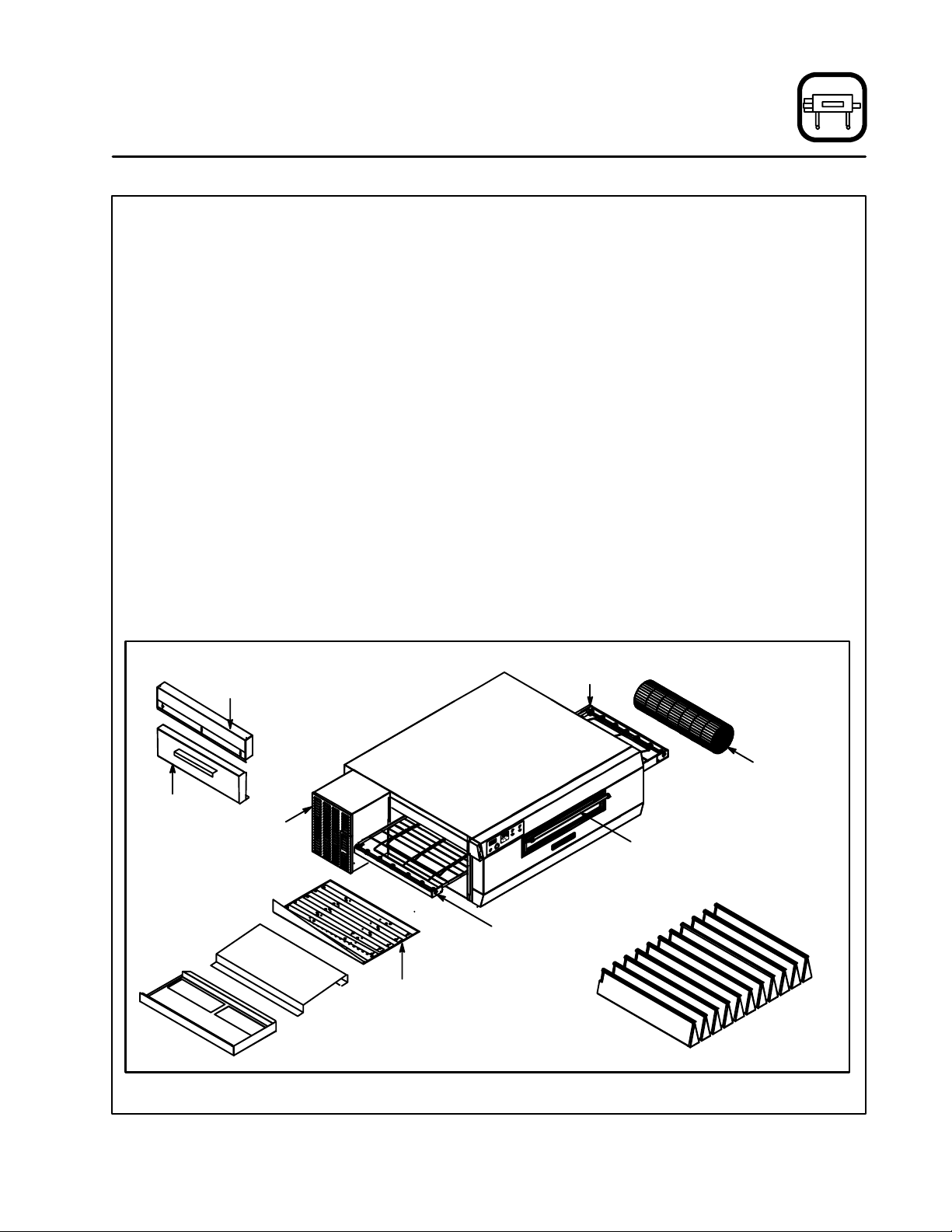
Oven Components
Conveyor Belt --- stainless steel chain link (con-
veyor) belt that carries product through the oven.
Conveyor Belt Master Links --- a l l o w e a s y r e m o v al of the conveyor belt for maintenance and cleaning. Identified by locating double spaces between
regular links on belt.
Conveyor Belt Support Assembly (drive & idle
sides) ---locatedonbothendsofovendeck.Drive
side support drives conveyor belt.
Control Box --- contains electrical wiring, cooling
fan, drive motor and drive chain.
Drive Motor --- provides power to move the conveyor belt.
Drive Chain --- connects the drive motor sprocket
to the drive side conveyor belt support sprocket.
Baking Chamber --- products pass through the
baking chamber on the conveyor belt for cooking.
Nozzles --- distribute heated air to the bottom of
the baking chamber. Located inside the oven, under the conveyor belt.
Upper
End Plug
Nozzle Hold-Down Bracket --- holds the front end
of the nozzles in position. Located inside the oven.
Return Air Diverters (2, drive and idle sides) --diverts return air from the baking chamber back to
the combustion chamber. Ensures even baking
throughout oven. Located inside the oven, beneath the nozzles.
Upper End Plug --- keeps heat in the baking
chamber. Located on each end above the conveyor belt.
Lower End Plug --- helps keep heat in the baking
chamber. Located at each end below t he conveyor belt.
Crumb Pan --- catches crumbs from products on
the conveyor. Located under conveyor belt at both
ends of the baking chamber.
Pull Down Door --- open for auxiliary product insertion.
Air Flow Plates (2, drive and idle sides) --- d i s tribute heated air to top of baking chamber. Located inside of oven at the top of baking chamber.
Conveyor Support
Assembly
Lower
End Plug
Crumb
Pan
Return Air
Diverter
Control
Box
Conveyor Belt
Handle for
Pull Down Door
Conveyor
Support
Assembly
Air Flow Plate
Nozzles
Figure 2
3
Page 8
Installation
Delivery and Inspection
All Blodgett ovens are shipped in containers to
prevent damage. Upon delivery of your new oven:
D
Inspect the shipping container for external damage. Any evidence of damage should be noted
on the delivery receipt which must be signed by
the driver.
D
Uncrate the oven and check for internal damage. Ca rriers will accept claims for concealed
damage if notified within fifteen days of delivery
and the shipping container is retained for inspection.
Part Description
Main oven body 1
Oven support/with caster
(2 locking, 2 non-locking)
Left conveyor belt support assembly 1
Rightconveyorbeltsupportassembly 1
Upper end plug assemblies 2
Lower end plug assemblies 2
Rolled wire belt** 1
Crumb pan 2
Nozzles 11
Window assembly 1
Air flow plate removal handle 1*
Qty.
4*
The Blodgett Oven Company cannot assume
responsibility for loss or damage suffered in
transit. The carrier assumed full responsibility
for delivery in good order when the shipment
was accepted. We are, however, prepared to
assist you if filing a cl aim is necessary.
The oven can now be moved to the installation
site. Check the following list with Figure 2 on page
3 to be sure all items were received.
Part Description Qty.
Packet containing:3/8”-16 bolts
(for oven supports)
Packet containing: flat & lock washers
(for oven supports)
Packet containing:
(2) 10 amp. motor circuit fuses,
(2) 2 amp. control circuit fuses
Packet containing: conveyor belt master
links**
Extra piece of wire conveyor belt** 1*
Owner’s manual 1*
Return air diverters 2
NOTE: * not shown on Figure 2
** Two of these items are included for
dual belt models
1*
1*
1*
1*
4
Page 9

Installation
Oven Location
LOCATION
The well planned and proper placement of your
oven will result in long term operator convenience
and satisfactory performance.
The following clearances must be maintained between the oven and any combustible or non-combustible construction.
D
Oven body sides --- 20” (51 cm)
D
Oven body back --- 2” (5 cm)
The following clearances must be available for servicing.
D
Oven body sides --- 38” (96.5 cm)
D
Oven body back --- 28” (71 cm)
It is essential that an adequate air supply to the
oven be maintained.
D
Place the oven in an area that is free of drafts.
D
Keep the oven area free and clear of all combustibles such as paper, cardboard, and flammable
liquids and solvents.
D
Do not place the oven on a curb base or seal to
a wall. This will restrict the flow of air and prevent
proper ventilation to the blower motors. This
condition must be corrected to prevent permanent damage to the oven.
General export installations
Installation must conform with Local and National
installation standards. Local installation codes
and/or requirements may vary. If you have any
questions regarding the proper installation and/or
operation of your Blodgett oven, please contact
your local distributor. If you do not have a local distributor, please call the Blodgett Oven Company at
0011-802-860-3700.
5
Page 10

Installation
Oven Assembly
OVEN SUPPORTS AND CASTERS
1. Bolt the supports to the oven with 3/8-16 hex
head bolts.
NOTE: Install the locking casters on the front
of the oven.
2. Carefully place the oven onto casters. Have
several persons lift the oven off the pallet and
set it onto the casters.
3. Engage the brakes on the front casters.
4. Remove the crating supports from the rear of
the oven.
RETURN AIR DIVERTERS
1. Slide the left and right air diverters into the bottom of the baking chamber. See Figure 4 for
proper orientation. The outside edges of the
diverters should be 3” (11.8 cm) from the edge
of the oven.
Front of
Oven
Figure 3
3” (11.8 cm)
Figure 4
Crating
Support
6
Page 11

Installation
Oven Assembly
NOZZLES
1. Install nozzles from center of oven working toward the ends. Make sure the bottom of
nozzle fits into the slot in the nozzle support toward the front of the oven.
2. Secure the nozzle hold-down strip across the
inside front of the oven using the existing
screws located on the oven wall.
Figure 5
CONVEYOR BELT SUPPORT
1. Slide the left conveyor support (with sprocket
on the end of the shaft) into the support tracks.
The sprocket must be inside the control box
after being pushed into the oven.
Figure 6
2. Install the drive chain around the drive motor
and the sprocket on the conveyor support.
Push the support back to tighten the chain.
Figure 7
3. Tighten the four bolts on the control box.
4. Slide the right conveyor support into the support tracks until it touches the left stop.
7
Page 12

Installation
Oven Assembly
CONVEYOR BELT
Be sure to install the belt from left to right. The conveyor belt has loops on both sides. The loops must
travel backwards on the conveyor support. See
Figure 8.
Belt Top
Direction of
Conveyor Travel
To thread the conveyor belt
1. Start from the right hand side of the oven, lowerlevelfirst.Unrollthebeltasshownin
Figure 9, otherwise the belt will be upside
down. Leave about one foot hanging out on
the left side
NOTE: If belt travel is from left to right, start
fromtheleftsideoftheoven.
2. Take the remainder of the belt, loop it around
the right shaft. Push through on the upper level.
3. The two ends of the belt should be approximately 6-9 inches past the left shaft on the upper level of the belt support. Right shaft if right
to left travel is required.
Figure 8
Unless specified otherwise, conveyor travel is factory set for left to right operation when facing the
front of the oven. To change direction:
D
Reverse the polarity of the drive motor. Interchange the black and white motor leads at the
D.C. controller located in the control panel.
D
Install the conveyor belt from the left side of the
oven.
Figure 9
Figure 10
8
Page 13
Installation
Oven Assembly
4. Install inner master links. See Figure 11 and
Figure 12.
Upside-down
Proper
Position
Figure 11
5. Install the outer master links. See Figure 13
and Figure 14
NOTE: The extra piece of wire belt can be used to
make additional master links if the original
links are lost or damaged.
Figure 13
Figure 12
Figure 14
9
Page 14

Installation
Oven Assembly
END PLUGS
1. Install the upper and lower end plugs at both
ends of the oven. Secure the upper end plugs
with two wing nuts on the bottom of each plug.
Upper End Plug
CRUMB PANS
1. Install crumb pans under each end of the conveyor. The oven is now ready to be rolled into
place and connected to gas/power supplies
for adjustment and start-up procedure.
Figure 16
Lower End Plug
Figure 15
10
Page 15

Before making any electrical connections to this
unit, check that the power supply is adequate for
the voltage, amperage, and phase requirements
stated on the rating plate.
NOTE: The rating plate is mounted on the control
box.
A wiring diagram accompanies this manual and is
also attached inside the control panel.
The MT3255E is available in two voltage options.
D
The 380/220 VAC oven requires a 60 Amp,
50Hz, 3Φ, 4 wire service consisting of L1, L2
neutral and ground.
D
The 415/240 oven requires a 60 Amp, 50Hz, 3Φ,
3 wire service consisting of L1, neutral an d
ground.
Use 90_C wire and size wire according to local
codes.
Installation
Electrical Connection
L1
415/380
L2
415/380
L3
N
Figure 17
THE BLODGETT OVEN COMPANY CANNOT ASSUME RESPONSIBILITY FOR LOSS OR DAMAGE
SUFFERED AS A RESULT OF IMPROPER INSTALLATION.
415/
380
240/
220
OvenSupply
11
Page 16

Operation
Safety Information
THE INFORMATION CONTAINED IN THIS SECTION IS PROVIDED FOR THE USE OF QUALIFIED
OPERATING PERSONNEL. QUALIFIED OPERATING PERSONNEL ARE THOSE WHO HAVE
CAREFULLY READ THE INFORMATION CONTAINED IN THIS MANUAL, ARE FAMILIAR WITH
THE FUNCTIONS OF THE OVEN AND/OR HAVE
HAD PREVIOUS EXPERIENCE WITH THE OPERATIONOF THE EQUIPMENT DESCRIBED. ADHERENCE TO THE PROCEDURES RECOMMENDED HEREIN WILL ASSURE THE
ACHIEVEMENT OF OPTIMUM PERFORMANCE
AND LONG, TROUBLE-FREE SERVICE.
Please take the time to read the following safety
and operating instructions. They are the key to the
successful operation of your Blodgett conveyor
oven.
SAFETY TIPS
For your safety read before operating
General safety tips:
D
DO NOT remove the control box cover unless
the oven is unplugged.
12
Page 17

Operation
Standard Controls
CONTROL DESCRIPTION
1. COOK TIME DISPLAY --- gives the belt speed.
2. UP and DOWN ARROW KEYS --- used to increase/decrease desired cook time
3. ACTUAL TEMPERATURE KEY --- press to display the actual oven temperature.
4. ACTUAL TEMPERATURE LIGHT --- when lit indicates the control is displaying the actual
oven temperature.
5. SETPOINT LIGHT --- when lit indicates control
is displaying desired cook temperature.
6. HEAT LIGHT --- when lit indicates that the control is calling for heat.
7. UP and DOWN ARROW KEYS --- used to increase/decrease desired cook temperature.
8. HEAT SWITCH --- used to ignite the burner.
9. BLOWER SWITCH --- controls power to the
blowers.
10. CONVEYOR SWITCH --- turn to ON to begin
conveyor travel.
OPERATION
1. TurnthemanualgasvalvetoOPEN.Thisis
only necessary on initial start-up.
2. Turn the BLOWER SWITCH (9) to ON.
3. Press the UP or DOWN ARROW keys (7) to
scroll to the desired cook temperature.
4. Turn the HEAT SWITCH (8) to ON.
NOTE: If the oven fails to ignite after the thirty
(30) second purge, turn the blower
switch to OFF. Wait five minutes before
turning the blower switch back to ON.
5. Press the ACTUAL TEMPERATURE KEY (3). If
the actual temperature matches the setpoint
the oven is ready to cook.
NOTE: The display flashes until the actual
temperature is within the preset deviation alarm band. The default setting is
¦ 20_F(12_C) of the setpoint.
6. Turn the CONVEYOR SWITCH (10) to ON.The
conveyor belt starts to move. Press the UP or
DOWN ARROW keys (2) to scroll to the desired cook time.
7. Turn the BLOWER (9), CONVEYOR (10) and
HEAT (8) SWITCHES to OFF. The Cool Down
circuit is energized. The blower motor(s) continue to run until the oven temperature is between 135-170_F (57-77_C). The blower motor(s) automatically shut off. For faster cool
down, open the window.
The oven holds these parameters daily and requires no further adjustments unless a new type
of product is placed in the oven.
NOTE: Each oven contains different components
and must be adjusted individually.
10
COOK TIME
ON OFF
CONVEYOR
1
ACTUAL SETPOINT HEAT
TEMPERATURE
6
83 4 5 72
ON OFF
HEAT
9
ON OFF
BLOWER
Figure 18
13
Page 18

Operation
Oven Adjustments for Cooking
The combination of belt time, oven temperature,
and air flow are important for achieving quality re sults from your Blodgett conveyor oven. Use the
following guidelines to adjust the belt time and
oven temperature of your unit. For questions regarding further oven adjustments, please contact
your local Blodgett Sales Representative for assistance.
CONVEYOR SPEED AND OVEN TEMPERATURE
Conveyor belt speed (cook time) and oven temperature are the two variables used w hen fine tuning your oven for a specific product. To determine
the optimum bake time and temperature, make
small changes for each trial and keep one variable
constant. For example, if the oven temperature is
460_F (238_C) and the belt speed is 7 minutes,
but the pizza is not browned enough, increase the
temperature to 475_F (246_C) and keep the belt
speed the same. However, if the center of the pizza
is not completely cooked, keep the oven temperature the same, and increase the bake time to 7
minutes and 30 seconds. In general, raise the
bake temperature to increase browning, and
lengthen the belt time to increase doneness.
FINISHED PRODUCT TEMPERATURES
Internal temperatures of the cooked products
should be measured immediately after the product exits the cooking chamber to ensure a safe
food temperature. Internal pizza temperatures
should be over 165_F(74_C). Minimum tempera-
ture guidelines vary depending on the food items.
Air flow adjustments may be necessary to fine
tune the oven for your particular product. The air
plate, located at the top of the baking chamber,
contains holes that can be covered using Block-off
Plates. The plates can easily be adjusted to regulate the air flow for your particular needs. Use the
following guidelines to adjust the Block-off Plates.
1. Ensure the oven is Off and completely cooled.
2. Remove both upper end plugs. Loosen the
wing nuts on the bottom of each end plug.
3. Loosen the wing screws holding the air plate
retainers in place. Remove the four wing
screws from the control box end of the oven.
Slide the air plates straight out from both ends
of the oven.
4. Remove the wing nuts, screws, and washers
holding the Block-off Plates.
5. Adjust the plates.
6. Replace the wing nuts, screws, and washers
to tightly secure the Block-off plates in their
new locations. Make a sketch of the final airplate setup for future reference.
NOTE: One or two block-off plates may be left
off entirely if appropriate to obtain the
desired results.
7. Replace the air plate and upper end plugs.
AIR FLOW AD JUSTMENTS
Slide the product clearance adjustment plates to
the lowest possible setting for your menu items.
Lowering the clearance plates will reduce the
amount of hot air escaping from the chamber
openings.
Most often, the ideal oven settings can be dialed
in without making any changes to the airplate. The
oven configuration should not be modified unless
the oven time and temperature adjustments have
proven unsuccessful.
Figure 19
14
Page 19

The following examples illustrate air flow regulation.
NOTE: The first half of the oven chamber greatly
affects the initial baking of the product,
while the last half largely affects the browning.
D
A good bake time and t emperature have been
established, but more top browning is desired.
Slide one of the Block-off Plates to uncover a
row of holes toward the exit end of the oven.
D
The bottom of the pizza is golden brown, but the
top is too dark. Close rows at the exit end of the
oven to reduce final browning.
D
The center of the pizza is still doughy and the
toppings are not fully cooked. Open up rows at
the chamber entrance and close rows at the
chamber exit.
Operation
Oven Adjustments for Cooking
Figure 20
15
Page 20

Maintenance
Cleaning
WARNING!!
Always disconnect the power supply before cleaning or servicing the oven.
Follow this recommended cleaning schedule for
proper oven performance.
Daily:
1. Clean the conveyor belt using a wire brush. Allow any foreign material to drop into the crumb
pans.
2. Empty and clean the crumb pans.
3. Make sure cooling fans are operating.
Every Three Months:
1. Brush and clean the guards of the cooling
fans.
Every Six Months:
1. Unplug the oven.
2. Remove both crumb pans from the ends of the
conveyor.
3. Remove both upper end plugs. Loosen the
wing nuts on the bottom of each end plug.
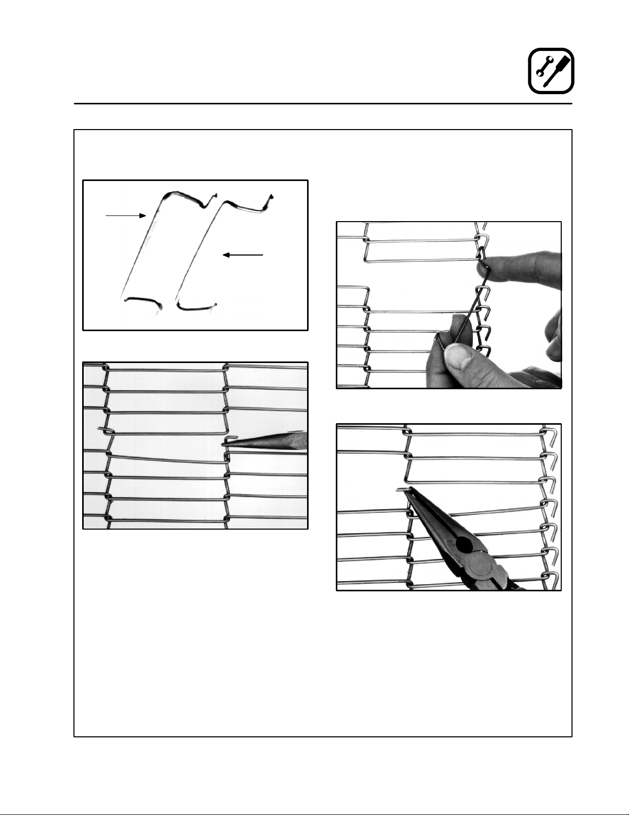
b.) Slide the belt out from one end. Be sure to
roll the belt as shown in Figure 22. Otherwisethebeltwillbeupsidedownwhenrethreading.
Figure 22
6. Remove the non-drive side conveyor support.
7. Remove the drive side conveyor support as
follows:
a.) Remove the 1/4” hex bolt and nut (inside
control box), that fastens the drive side
conveyor support to the control box. See
Figure 23.
b.) Remove the drive chain from the sprocket
by pushing the conveyor assembly in to
loosen the chain. If unable to push assembly, loosen motor mounts.
c.) Slide the conveyor support out of the
oven.
Figure 21
4. Remove both lower end plugs.
5. Remove the conveyor belt as follows:
a.) Use needle-nose pliers to remove the
conveyor belt master links.
Figure 23
16
Page 21

Maintenance
Cleaning
8. Using the handle supplied with the oven, pull
out the air plate.
Figure 24
9. Remove the nozzles as follows:
a.) Remove the bolt from the hold down
bracket. Lift the bracket straight up and
slide out either end of the oven.
11. Soak the conveyor in a hot water/detergent
mix.
12. Clean the crumb pans, return air diverters,
nozzles, air plates, and end plugs with a hot
water/detergent mix. Rinse with clean water.
For difficult cleaning use a heavy duty degreaserorovencleanerthatissafeforaluminum.
NOTE: DO NOT immerse the end plugs. They
contain insulation.
13. Clean the oven interior with an all purpose
cleaneroranovencleanerthatissafeforaluminum.
14. Move the oven to clean underneath. DO NOT
damage the gas hose or electrical cords when
moving.
Every 12 Months:
A factory authorized service person should:
1. Open and clean the inside of the control panel.
2. Check a nd tighten all electrical connections.
3. Check DC gear motor brushes for wear.
4. Check conveyor drive chain for cleanliness
and proper lubrication.
If maintenance is required contact your local service company, a factory representative or the
Blodgett Oven company.
Figure 25
b.) Push the nozzles toward the back w all of
the oven. Lift the front end and turn it toward you slipping the back end from the
duct.
10. Slide the return air diverters out of the oven.
WARNING!!
Always disconnect the power supply before cleaning or servicing the oven.
17
Page 22

Maintenance
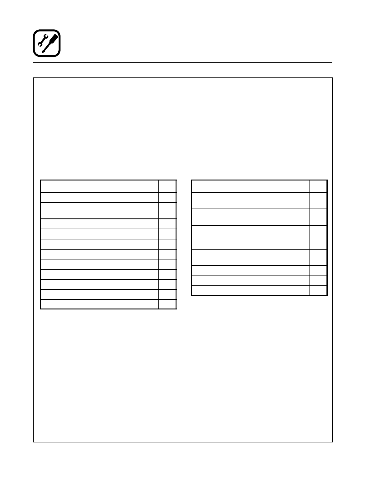
Troubleshooting Guide
POSSIBLE CAUSE(S) SUGGESTED REMEDY
SYMPTOM: Blower Motor(s) not running
S
BlowercontrolswitchinOFFposition
S
No power to oven
S
Motor fuses blown
S
Motor(s) burned out
S
Control circuit fuse blown (right fuse on control
panel door)
SYMPTOM: Main temperature control displays EEE
S
Temperature controller not properly installed
S
Internal problem with main temperature control
S
Loose thermocouple connections at main
temperature control
S
Short in thermocouple
S
Turn to ON position
S
Replace main fuses or reset breakers
S
Replace fuses
S
*
S
Replace fuses
S
Reinstall
S
*
S
*
S
*
SYMPTOM: Burner will not fire
S
BlowercontrolswitchinOFFposition
S
Blower motor(s) not running
S
Front cooling fan not working properly
S
Defective main temperature controller
S
Main temperature controller not set above
ambient t emperature
*Denotes remedy is a difficult operation and should be performed by qualified personnel only. It is recommended, however, that
All repairs and/or adjustments be done by your local Blodgett service agency and not by the owner/operator. Blodgett cannot assume responsibility for damage as a result of servicing done by unqualified personnel.
WARNING!!
Always disconnect the power supply before cleaning or servicing the oven.
S
Turn to ON position
S
Blower motor(s) must be running. Check control
switch and/or fuses.
S
*
S
*
S
Set to desired temperature
18
Page 23

POSSIBLE CAUSE(S) SUGGESTED REMEDY
SYMPTOM: Oven will not reach desired temperature
S
Heat control switch OFF
S
No power to oven
S
Blower motor(s) not running
S
Defective heating element relay
S
Shorted thermocouple
S
Heating element(s) burned out
S
Temperature hi-limit switch out of adjustment or
defective
S
Internal problem with main temperature control
S
Front cooling fans not working properly
SYMPTOM: Conveyor belt will not run
Maintenance
Troubleshooting Guide
S
Turn to ON position
S
Replace main fuses
S
Check control switch and/or fuses
S
*
S
*
S
*
S
*
S
*
S
*
S
Conveyor control switch in OFF position
S
Control circuit fuse blown (left fuse on back of
control box)
S
Belt hooked on something in oven
S
Defectiveconveyordrivemotor
S
Defectiveconveyordrivemotorcontroller
*Denotes remedy is a difficult operation and should be performed by qualified personnel only. It is recommended, however, that
All repairs and/or adjustments be done by your local Blodgett service agency and not by the owner/operator. Blodgett cannot assume responsibility for damage as a result of servicing done by unqualified personnel.
WARNING!!
Always disconnect the power supply before cleaning or servicing the oven.
S
Turn to ON position
S
Replace fuse
S
Turn conveyor to OFF, unhook and repair problem
S
*
S
*
19
Page 24

CUSTOMER
INSERT
WIRING DIAGRAM
HERE
 Loading...