

Page 1

MT3240 SERIES
CONVEYOR OVENS
SERVICE AND REPAIR MANUAL
BLODGETT OVEN COMPANY
www.blodgett.com
50 Lakeside Avenue, Box 586, Burlington, Vermont 05402 USA Telephone (802) 658Ć6600 Fax: (802)864Ć0183
PN M9911 Rev C (11/01)
2001 - G.S. Blodgett Corporation
Page 2

TABLE OF CONTENTS
This page intentionally left blank.
ii
Page 3

TABLE OF CONTENTS
1. INTRODUCTION
Oven Specifications 1-1. . . . . . . . . . . . . . . . . . . . . . . . . . . . . . . . . . . . . . . . . . . . . . . . . . . . . . . . . . . . . . .
Ventilation Requirements 1-1. . . . . . . . . . . . . . . . . . . . . . . . . . . . . . . . . . . . . . . . . . . . . . . . . . . . . . .
Electrical Specifications 1-3. . . . . . . . . . . . . . . . . . . . . . . . . . . . . . . . . . . . . . . . . . . . . . . . . . . . . . . .
Gas Specifications 1-5. . . . . . . . . . . . . . . . . . . . . . . . . . . . . . . . . . . . . . . . . . . . . . . . . . . . . . . . . . . .
2. OPERATION
Computer Controller 2-1. . . . . . . . . . . . . . . . . . . . . . . . . . . . . . . . . . . . . . . . . . . . . . . . . . . . . . . . . . . . . .
Sequence of Operation 2-3. . . . . . . . . . . . . . . . . . . . . . . . . . . . . . . . . . . . . . . . . . . . . . . . . . . . . . . . . . . .
MT3240G Domestic and General Export - M4193 Rev C 2-3. . . . . . . . . . . . . . . . . . . . . . . . . .
MT3240E domestic and General Export - M4196 Rev C 2-5. . . . . . . . . . . . . . . . . . . . . . . . . . .
MT3240G Australia - M4174 Rev A 2-6. . . . . . . . . . . . . . . . . . . . . . . . . . . . . . . . . . . . . . . . . . . . .
MT3240G CE - M4172 Rev C 2-8. . . . . . . . . . . . . . . . . . . . . . . . . . . . . . . . . . . . . . . . . . . . . . . . . .
MT3240e CE - M6509 Rev C 2-10. . . . . . . . . . . . . . . . . . . . . . . . . . . . . . . . . . . . . . . . . . . . . . . . . .
Oven Adjustments for Cooking 2-17. . . . . . . . . . . . . . . . . . . . . . . . . . . . . . . . . . . . . . . . . . . . . . . . . . . . .
3. CALIBRATION AND ADJUSTMENT
Convection Blower Motors 3-1. . . . . . . . . . . . . . . . . . . . . . . . . . . . . . . . . . . . . . . . . . . . . . . . . . . . . . . . .
Regulated Gas Pressure 3-2. . . . . . . . . . . . . . . . . . . . . . . . . . . . . . . . . . . . . . . . . . . . . . . . . . . . . . . . . . .
Computer Controller Configuration 3-3. . . . . . . . . . . . . . . . . . . . . . . . . . . . . . . . . . . . . . . . . . . . . . . . . .
Temperature Calibration 3-5. . . . . . . . . . . . . . . . . . . . . . . . . . . . . . . . . . . . . . . . . . . . . . . . . . . . . . . . . . .
Belt Speed Calibration 3-6. . . . . . . . . . . . . . . . . . . . . . . . . . . . . . . . . . . . . . . . . . . . . . . . . . . . . . . . . . . .
Closed Loop System 3-6. . . . . . . . . . . . . . . . . . . . . . . . . . . . . . . . . . . . . . . . . . . . . . . . . . . . . . . . . .
Open Loop System - Single belT 3-7. . . . . . . . . . . . . . . . . . . . . . . . . . . . . . . . . . . . . . . . . . . . . . .
Open Loop System - Twin Belt 3-8. . . . . . . . . . . . . . . . . . . . . . . . . . . . . . . . . . . . . . . . . . . . . . . . .
Rerating the Appliance 3-9. . . . . . . . . . . . . . . . . . . . . . . . . . . . . . . . . . . . . . . . . . . . . . . . . . . . . . . . . . . .
Checking the Firing Rate 3-10. . . . . . . . . . . . . . . . . . . . . . . . . . . . . . . . . . . . . . . . . . . . . . . . . . . . . . . . . .
4. TROUBLESHOOTING
DC Drive System 4-1. . . . . . . . . . . . . . . . . . . . . . . . . . . . . . . . . . . . . . . . . . . . . . . . . . . . . . . . . . . . . . . . .
Computer Control System 4-2. . . . . . . . . . . . . . . . . . . . . . . . . . . . . . . . . . . . . . . . . . . . . . . . . . . . . . . . .
Heating System 4-3. . . . . . . . . . . . . . . . . . . . . . . . . . . . . . . . . . . . . . . . . . . . . . . . . . . . . . . . . . . . . . . . . .
Convection System 4-5. . . . . . . . . . . . . . . . . . . . . . . . . . . . . . . . . . . . . . . . . . . . . . . . . . . . . . . . . . . . . . .
Reference Tables 4-7. . . . . . . . . . . . . . . . . . . . . . . . . . . . . . . . . . . . . . . . . . . . . . . . . . . . . . . . . . . . . . . . .
Heating Element Resistance 4-7. . . . . . . . . . . . . . . . . . . . . . . . . . . . . . . . . . . . . . . . . . . . . . . . . . . .
Probe Resistance vs Temperature 4-7. . . . . . . . . . . . . . . . . . . . . . . . . . . . . . . . . . . . . . . . . . . . . . .
i
Page 4

TABLE OF CONTENTS
This page intentionally left blank.
ii
Page 5

CHAPTER 1
INTRODUCTION
Page 6

MT3240 Series
OVEN SPECIFICATIONS
VENTILATION REQUIREMENTS
A mechanically driven ventilation system is reĆ
quired for the removal of excess heat and cooking
vapors. For gas models, a ventilation system is
also required for the removal of the products of gas
combustion. The necessity for a properly designed
and installed ventilation system cannot be over
emphasized.
The following are general recommendations and
guidelines for good ventilation. Your specific apĆ
plication may require the services of a ventilation
engineer or consultant
The ventilation hood must work well with the building
heating, ventilation and air conditioning (HVAC) sysĆ
tem. The hood exhaust and the supply air flows
should be sized appropriately. Supply air must be
provided by either the hood system or the building
HVAC system in order to prevent a negative presĆ
sure in the oven area. Supply air should replace
approximately 80% of the air flow exhausted by the
hood. The table below can be used as a guideline,
but the correct air flow values depend on the effiĆ
ciency of the hood design, the amount of air flow
around the oven, and the current air flow in and out
of the kitchen or oven area (for existing facilities).
SINGLE DOUBLE TRIPLE
Exhaust Volume - CFM (M3/min)
800Ć1000
(23Ć28)
Supply Requirements - CFM (M3/min)
640Ć800
(18Ć23)
Ideally, supply air is provided through the building
HVAC system or, secondly, through the hood with an
inĆline tempering unit. Air supplied directly from outĆ
side the building to the kitchen or oven area, nonĆ
1200Ć1600
(34Ć46)
960Ć1280
(27Ć36)
TABLE 1
2000Ć2400
(57Ć68)
1600Ć1920
(46Ć54)
tempered, can be used as supply air but the design
must accommodate potential operational and enviĆ
ronmental drawbacks.
NOTE: In NO case should supply air blow at or
near the cooking chamber openings as
that would adversely affect the cooking
consistency and the reliability of the oven.
The hood should be sized to completely cover the
equipment plus an overhang of at least 6" (15cm)
on all sides not adjacent to a wall. The distance
from the floor to the lower edge of the hood should
not exceed 7' (2.1m). See FIGURE 1.
U.S. and Canadian installations
Refer to your local ventilation codes. Requirements
may vary by city, county, province or state. In the
absence of local codes, refer to the National venĆ
tilation code titled, Standard for the Installation of
Equipment for the Removal of Smoke and Grease
Laden Vapors from Commercial Cooking EquipĆ
ment", NFPAĆ96ĆLatest Edition.
General export installations
Installation must conform with Local and National
installation standards. Local installation codes
and/or requirements may vary. If you have any
questions regarding the proper installation and/or
operation of your Blodgett oven, please contact
your local distributor. If you do not have a local disĆ
tributor, please call the Blodgett Oven Company at
0011Ć802Ć860Ć3700.
WARNING:
Failure to properly vent the oven can be hazardĆ
ous to the health of the operator and may result
in operational problems, unsatisfactory baking
and possible damage to the equipment.
Damage sustained as a direct result of improper
ventilation will not be covered by the ManufacturĆ
er's warranty.
1-1
Page 7
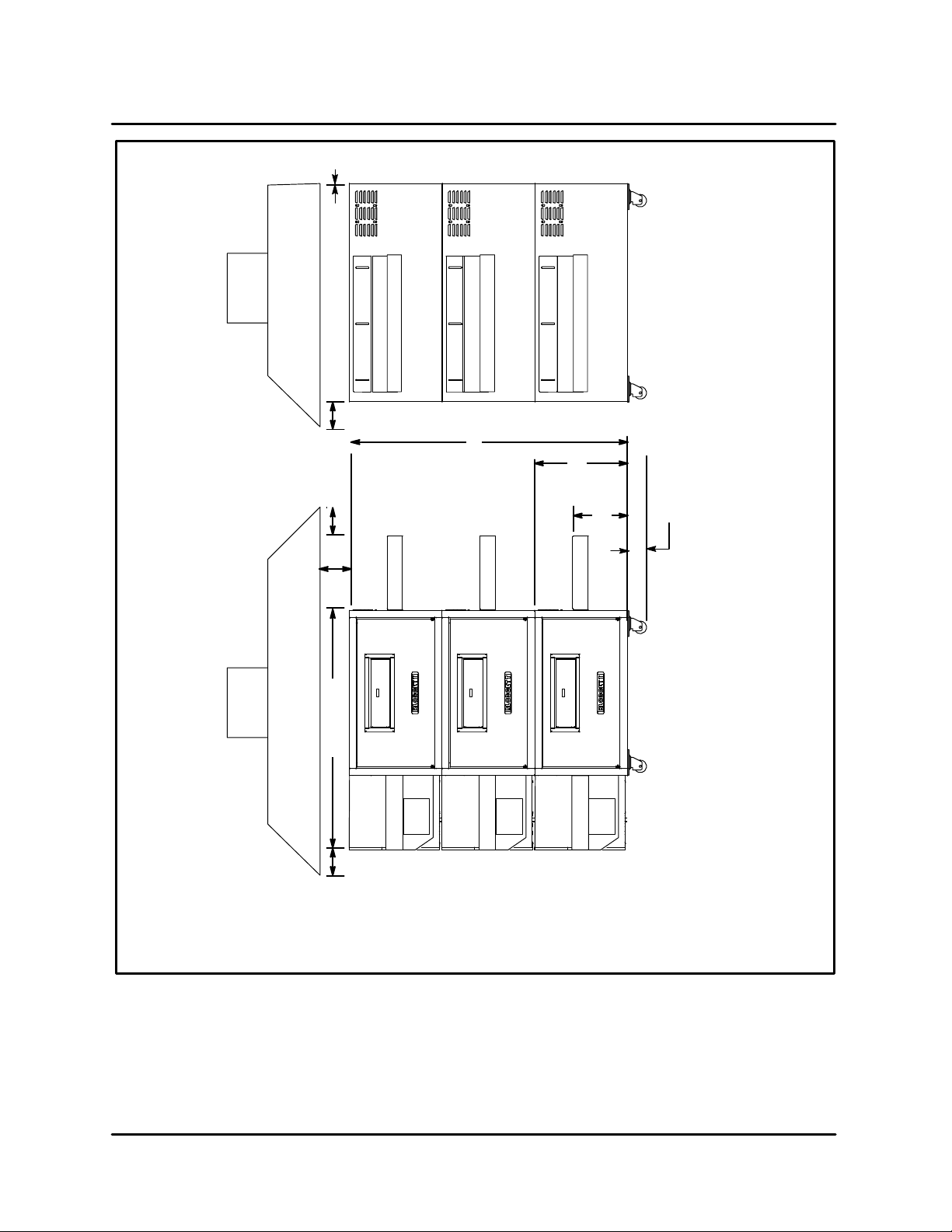
0" (0cm) if wall or
6" (15.2 cm)
INTRODUCTION
3" (7.6 cm)
Minimum
6" (15 .2cm)
Minimum
77" (196 cm)
72" (182 cm)
24"
(61 cm)
14"
(35.5 cm)
Triple Stack - 7" (17.8 cm)
Double Stack - 17.25" (43.8 cm)
Single Stack - 23.25" (59 cm)
SG3240 Series Shown
6" (15.2 cm)
Minimum
FIGURE 1
1-2
Page 8

MT3240 Series
ELECTRICAL SPECIFICATIONS
MT3240G
U.S. and Canadian installations
The MT3240G requires a 15 Amp, 60HZ, 1F,
208Ć240VAC, 4 wire service consisting of L1, L2,
neutral and ground. Wiring from the power source
to these units must be a minimum of #16 AWG CU.
stranded wire or larger.
Single phase units MUST NOT be connected to the
high leg of a three phase system. The high leg reĆ
fers to a potential of 240 volts between one phase
and neutral. The remaining two legs have a potenĆ
tial of 120 volts between each phase and neutral.
General export installations
The MT3240G requires a 15 Amp, 50Hz, 1F,
220Ć240 VAC, 3 wire service consisting of L1, neuĆ
tral and ground. Use 90C wire and size wire acĆ
cording to local codes.
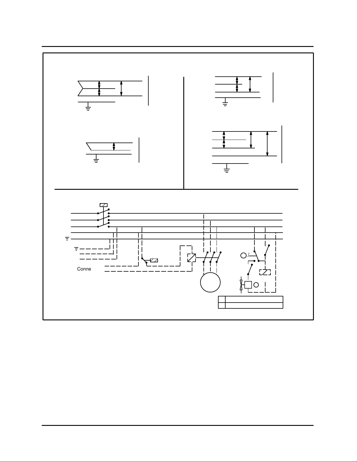
CE Approved installations
Connect exhaust fan connector 1 and 2. See
FIGURE 2.
Connect phase + neutral + ground .
MT3240E
U.S. and Canadian installations
The MT3240E requires a 80 amp, 60 HZ, 3F,
208Ć240 VAC 4 wire service consisting of L1, L2, L3,
and ground. Use 90C wire and size to National
Electric or local codes.
General export installations
The MT3240E requires a 56 amp, 50 HZ, 3F,
220Ć240 VAC, 4 wire service consisting of L1, L2, L3
and ground. Use 90C wire and size to National
Electric or local codes.
CE Approved installations
Connect the oven to a separate group 230V, 50 hz
with rigid connection and circuit breaker. The cirĆ
cuit breaker should disconnect all poles, including
neutral with a contact separation of at least 3 mm.
Connect L1 + L2 + L3 + neutral + ground.
THE BLODGETT OVEN COMPANY CANNOT ASĆ
SUME RESPONSIBILITY FOR LOSS OR DAMAGE
SUFFERED AS A RESULT OF IMPROPER INSTALĆ
LATION.
WARNING!!
Incorrect single phase wiring may result in exĆ
tensive damage to electrical components and
fire in the electrical box.
1-3
Page 9
INTRODUCTION
MT3240G
L1
120
N
120
L2
U.S. and Canadian Installations
L1
N
General Export Installations
L3
L2
L1
N
208Ć240
220Ć240
MT3240E
L1
L2
OvenSupply
OvenSupply
L3
U.S. and Canadian Installations
L1
415/380
L2
415/380
L3
N
General Export Installations
208Ć240
415/
380
240/
220
2Ć4Ć92
OvenSupply
OvenSupply
Blodgett
Connector
N
L
Connector
1
2
MT3240G CE Approved Installations
FIGURE 2
Fan
s
2
A2
21Air Pressure Regulator
Burner Control Solenoid
A1
Relay A
1
1-4
Page 10
MT3240 Series
GAS SPECIFICATIONS
GAS CONNECTIONS
Domestic and General Export installations
The gas line should be large enough to accommoĆ
date the peak demand of all the gas appliances.
TABLE 2 reflects a straight line, 50 foot run with no
coupling restrictions and no other appliances
drawing service. Gas line installations MUST conĆ
form to National Fuel Gas Code NFPA 54/ANSI
Z223.1 Sec. 1.4 (Latest Edition). TABLE 2 should
be used as a guideline only.
NOTE: For any pipe runs over 50 feet (15 m), conĆ
sult the factory.
CE approved installations
1. Connect the oven to the gas line with the propĆ
er type of gas according to Local and National
Installation Standards. See TABLE 2.
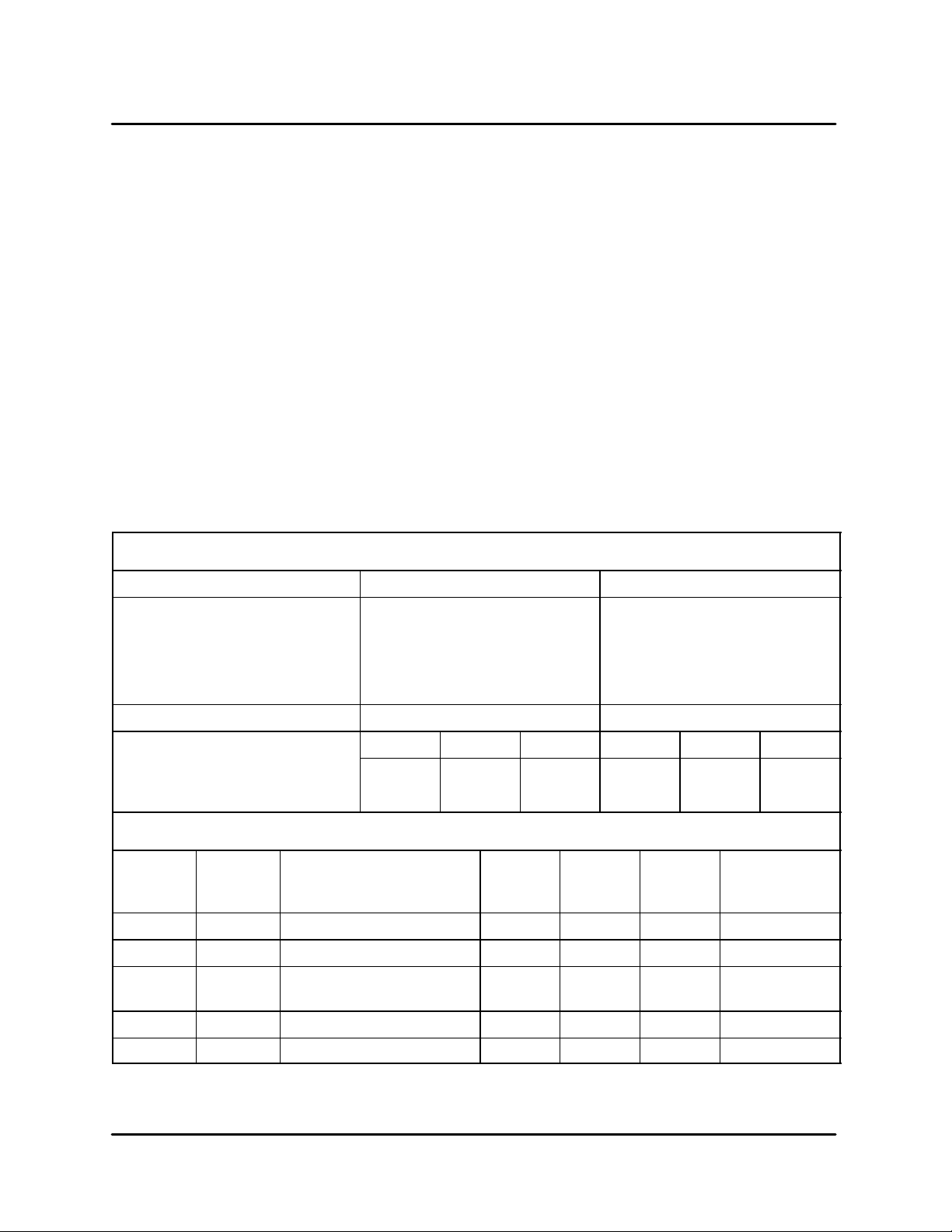
DOMESTIC AND GENERAL EXPORT
Natural Gas Propane Gas
Gas Line Sizing
GAS REQUIREMENTS
The firing rate for both the MT3240G is 100,000
BTU/Hr. (29.3 kW/Hr.) (105 MJ/hr)
NOTE: For natural gas meter sizing, consult your
local gas company to ensure that your meĆ
ter will provide the proper supply.
Installations within the U.S.
1. Add the total BTU's/hr of all the gas
appliances.
2. Convert BTU's to cubic ft/hr using the formula
Cu Ft/Hr = 1000 BTU/Hr for natural gas.
3. Size the meter accordingly.
Installations outside the U.S.
1. Add the total M3/min of all the appliances.
2. Size the meter accordingly.
Single
Double
Triple
Orifice Size #X #X
Incoming Gas Pressure W.C. kPa mbar W.C. kPa mbar
Static
Operational
CE APPROVED UNITS
Type of
Gas
G25 25 12 4,8 8 2 x 0,63 31,7 Nat. Gas
G20 20 8 4,8 8 2 x 0,63 31,7 Nat. Gas
G20/G25 20/25 Totally Inscrewed
G30 30/50 17 2,8 8 2 x 0,30 31,7 Butane
G31 30/37/50 24 2,8 8 2 x 0,30 31,7 Propane
Inlet
Pressure
mbars
Burner Pressure
Pressure Regulator
7"
5.5"
mbars
3/4" line
1Ć1/4" line
1Ć1/4" line
1.74
1.36
Injector
Diameter
TABLE 2
3/4" line
1" line
1Ć1/4" line
17.4
13.7
Opening
mm
4,8 8 2 x 0,63 31,7 Nat. Gas
Air
mm
12.5"
11"
Pilot
Injector
mm
3.11
2.73
Standard
Delivery
Value kW (HS)
31.1
27.4
1-5
Page 11

CHAPTER 2
OPERATION
Page 12
MT3240 Series
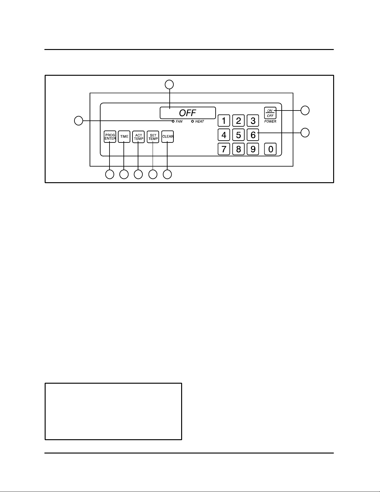
COMPUTER CONTROLLER
9
1
2
3
45678
FIGURE 3
CONTROL DESCRIPTION
1. DIGITAL DISPLAY - Displays the time, temĆ
perature and controller related information.
2. OVEN ON/OFF - Controls power to the oven.
3. NUMERIC KEYS - Used to enter numerical
data in the programming mode.
4. CLEAR KEY - Used to clear the display if an
error is made in the programming mode.
5. SET TEMP KEY - Used to view or program the
temperature setpoint.
6. ACT TEMP KEY - Used to view the current
oven temperature.
7. TIME KEY - Used to view or program the cook
time.
8. PROG/ENTER KEY - Used to enter and exit
the programming mode. Also used to lock in
programmed settings.
9. STATUS LAMPS - When lit indicate that the
fan or burners are operating.
This oven, supplied with remote control, is
equipped with an emergency shut down
switch. Should you need to stop the belt,
fans, or heat press the emergency switch.
CONTROL OPERATION
To turn the oven on:
1. Press and hold the ON/OFF key (2). The disĆ
play reads OFF when the oven is idle.
2. The display flashes WAIT LOW SET TIME.
3. The FAN and HEAT status lamps (9) light. The
fans begin to run. The heat rises to the proĆ
grammed temperature. The conveyor belt
travels at the programmed speed.
To view the cook time setting:
1. Press the TIME key (7). The LED on the key
lights and the display flashes SET TIME.
To display the actual oven temperature:
1. Press the ACT TEMP key (6). The LED on the
key lights and the display reads ACTUAL F.
To view the temperature set point:
1. Press the SET TEMP key (5). The LED on the
key lights and the display flashes SET TEMP
F.
To turn the oven off:
1. Press the ON/OFF key (2). The blower moĆ
tor(s) continue to run regardless of the controlĆ
ler status until the temperature drops below
180F (82C).
Do not use the emergency switch as a
GENERAL on/off switch!
2-1
Page 13

OPERATION
PROGRAMMING PROCEDURES
Programming the Cook Time:
1. Press the PROGRAM/ENTER key (8).
2. Press the TIME key (7). The display reads
PROGĆ?
SET TIMEĆ? _ _ _ _.
3. Use the NUMERIC keys (3) to enter the desired
cook time. The display will read the numbers
as they are entered. If an error is made, press
the CLEAR key (4) and reĆenter the number.
4. Press the PROGRAM/ENTER key (8) a second
time to lockĆin the new time. The new cook time
will be stored in the computer's memory.
Programming the Temperature:
1. Press the PROGRAM/ENTER key (8).
2. Press the SET TEMP key (5). The display reads
PROGĆ? SET TEMPĆ? _ _ _ _F.
3. Use the NUMERIC keys (3) to enter the desired
temperature set point. The control displays the
numbers as they are entered. If an error is
made, press the CLEAR key (4) and reĆenter
the number.
4. Press the PROGRAM/ENTER key (8) a second
time to lockĆin the new temperature. The new
temperature setpoint will be stored in the comĆ
puter's memory.
Operation at the Programmed Settings:
DISPLAY INFORMATION
WAIT LOW - indicates that the present oven
temperature is lower than the set point temperĆ
ature. When the oven reaches the set point
temperature the display changes to READY.
READY - indicates that the oven is ready to acĆ
cept product.
SET TEMP mmss - indicates the current
cook time setting.
HIGH TIME - indicates that the temperature
is well above the set point. This usually occurs
when moving from a higher āto a lower temperaĆ
ture. Wait until the display reads ready before
loading product.
HIGH TEMP LIMIT - indicates that the oven
temperature exceeds the high limit from the
2nd level program. The Over Temperature
Alarm buzzer will sound. Shut the oven off and
wait for the unit to cool down.
HIGH TEMP PANEL - indicates that the conĆ
trol area reaches an excessive temperature.
Shut the oven off and wait for the unit to cool
down. Error code generally means loose
ground wire.
PROBE OPEN PROBE SHORT - indicates
that the temperature sensor has failed. The
Alarm buzzer sounds. Shut the oven off and
contact a service representative.
1. Press and hold the ON/OFF key (2).
2. The FAN and HEAT status lamps (9) light. The
fans begin to run. The heat rises to the temperĆ
ature setting stored in the computer's memory.
The conveyor belt begins to travel at the timed
speed stored in memory.
3. The display will flash WAIT LOW SET TIME
until the programmed bake temperature is
reached. The HEAT lamp (9) will remain lit until
the oven reaches the temperature set point.
4. The display reads READY and the HEAT lamp
(9) goes out.
5. The oven is now ready to accept product.
6. Press and hold the ON/OFF key (2) to turn the
oven off. The fans continue to run while the
oven cools to a safe temperature.
2-2
Page 14

MT3240 Series
SEQUENCE OF OPERATION
NOTE: The following instructions represent the most common configurations. For questions regarding othĆ
er options call the Blodgett Service Department at (800)331Ć5842.
MT3240G DOMESTIC AND GENERAL EXPORT - M4193 REV C
COMPONENT REFERENCE
NOTE: Refer to FIGURE 4 page 2-12 for compoĆ
nent locations.
1. COOKING COMPUTER (FW525)
2. BELT STOP RELAY (22672)
3. BLOWER RELAY (22672)
4. HEAT RELAY (22672)
5. DC SPEED CONTROL BOARD (M2379)
6. SPST THERMAL SWITCH (M1362 L140Ć20F,
M2734 L163Ć30F)
7. HI LIMIT SWITCH (M3295)
8. 115/24 STEP DOWN TRANSFORMER (M2381)
9. COMBUSTION MOTOR (22132)
10. CENTRIFUGAL SWITCH
11. IGNITION MODULE (M1054)
12. PILOT VALVE (LP - 22190, Natural - M5495)
13. BURNER VALVE (LP - 22190, Natural - M5495)
14. MOTOR CONTACTOR (M0708)
15. CONVECTION FANS
16. SPDT THERMAL SWITCH (M3453 L140Ć20F)
17. COOLING FANS (M2469)
18. RTD PROBE (M7427)
19. 130 VDC MOTOR (M2378)
20. 240/120 STEP DOWN TRANSFORMER
(M2352)
OPERATION
1. Apply power to the oven. Program the time and
temperature into the computer (1). The belt
stop relay (2), blower relay (3) and the heat
relay (4) energize powering up the oven.
2. When the belt stop relay closes, 120 VAC goes
to the DC speed control board (5) and one terĆ
minal of a SPST thermal switch (6). If switch is
closed, power goes to the manual resetable hi
limit switch (7).
NOTE: The high limit switch is a bulb and capĆ
illary style switch. It reacts when the
oven cavity temperature exceeds the
high limit programmed into the cookĆ
ing computer.
NOTE: The thermal switch is located in the conĆ
trol compartment. This switch opens
when the face of the switch sees 1405F
and closes when there is a 10Ć205 drop
in temperature across the face of the
switch. The switch interrupts the heat
circuit.
If the high limit switch is closed power flows to
the primary side of a 115/24 volt step down
transformer (8) and the combustion motor (9)
of the flame blower. The combustion motor
powers up. When the combustion motor
reaches full speed, a centrifugal switch (10)
closes sending 24 VAC to the ignition module
(11). After the module's self diagnostics are
complete, the pilot valve (12) opens. A proof of
flame allows the burner valve (13) to cycle on
and off for every call for heat.
3. The blower relay sends 115 volts to the coil of
the motor contactor (14) starting the two conĆ
vection fans (15) in the rear of the oven. This
contactor also supplies power to the N.C. terĆ
minal of a SPDT thermal switch (16). The
switch toggles if the temperature passing its
face exceeds the rating on the back of the
switch and may start the fans even if the oven
is off. If this switch is cold, it should be made
between common and N.C. terminals sending
power to the cooling fans (17).
2-3
Page 15

NOTE: The SPDT thermal switch is located in
the junction box in the rear of the oven
in the blower compartment.
4. On a call for heat from the cooking computer
as sensed by an RTD probe (18), the heat relay
closes sending 24 VAC to the burner valve.
This valve opens sending gas to the flame
blower for ignition.
NOTE: The RTD probe is located in the back of
the oven in the convection fan compartĆ
ment. It should be checked with an ohm
meter.
5. The conveyor is driven by an open loop DC
control system consisting of a DC speed conĆ
trol board, a 130 VDC motor (19) and the DAC
located in the cooking computer. If a time is
programmed into the cooking computer, a
voltage ranging between .47 and 4.7 is applied
to the DC speed control board. The output voltĆ
age measured at A1 and A2 of the board to the
motor varies from 20 to130 VDC based on the
DAC voltage applied to the board or the time
programmed into the computer.
OPERATION
NOTE: The DAC receives 20 VDC from the
speed control boards. The DAC reĆ
turns a portion of the voltage (between
.47 and 4.7 VDC). The amount of voltĆ
age is dependent on the time proĆ
grammed into the computer.
NOTE: This type of system does not sense the
weight of the product and will slow
down slightly if the belt is fully loaded.
NOTE: The control voltage is supplied by a
240/120 step down transformer (20). The
transformer is located in the control
compartment.
2-4
Page 16

MT3240 Series
MT3240E DOMESTIC AND GENERAL EXPORT - M4196 REV C
COMPONENT REFERENCE
NOTE: Refer to FIGURE 5 page 2-13 for compoĆ
nent locations.
1. COOKING COMPUTER (FW525)
2. BELT STOP RELAY (22672)
3. BLOWER RELAY (22672)
4. MOTOR CONTACTOR (M0708)
5. CONVECTION FANS
6. SPDT THERMAL SWITCH (M2453 140Ć20F)
7. COOLING FANS (M2469)
8. RTD PROBE (M7427)
9. SPST THERMAL SWITCH (M1362 L140Ć20F)
10. HIGH LIMIT SWITCH (M3295)
11. HEAT RELAY (22672)
12. MERCURY CONTACTOR
13. DC SPEED CONTROL BOARD (M2379)
14. 130 VDC MOTOR (M2378)
OPERATION
1. Apply power to the oven. Program the time and
temperature into the computer (1). The belt
stop relay (2) and blower relay (3) energize
powering up the oven.
2. The blower relay sends 115 volts to the coil of the
motor contactor (4) starting the two convection
fans (5) in the rear of the oven. Power is also apĆ
plied to the N.C. terminal of a SPDT thermal
switch (6). The switch toggles if the temperature
passing its face exceeds the rating on the back
of the switch and may start the fans even if the
oven is off. If this switch is cold, it should be
made between common and N.C. terminals
sending power to the cooling fans (7).
NOTE: The SPDT thermal switch is located in
the cooking computer control compartĆ
ment. This switch toggles when the temĆ
perature passing its face exceeds the
rating on the back of the switch and
closes when there is a 10Ć205 drop in
temperature across the face of the
switch.
3. On a call for heat from the cooking computer, as
sensed by an RTD probe (8), the heat relay (11)
closes sending 115 VAC to one side of a SPST
thermal switch (9). If the switch is closed power
goes to one terminal of the manual resettable high
limit switch (10). If this switch is closed 115VAC
goes to the coil of a mercury contactor (12).
NOTE: The thermal switch is located in the conĆ
trol compartment. This switch opens
when the face of the switch sees 1405F
and closes when there is a 10Ć205 drop
in temperature across the face of the
switch. The switch interrupts the heat
circuit.
NOTE: The high limit switch is a bulb and capĆ
illary style switch. It reacts when the
oven cavity temperature exceeds the
high limit programmed into the cookĆ
ing computer.
NOTE: When the coil is energized on the conĆ
tactor, mercury is displaced completing
a circuit within the contactor, sending
power to the heating elements.
NOTE: The RTD probe is located in the rear of
the oven in the convection fan compartĆ
ment.
4. The conveyor is driven by an open loop DC
control system consisting of a DC speed conĆ
trol board (13), a 130 VDC motor (14) and the
DAC located in the cooking computer. If a time
is programmed into the cooking computer, a
voltage ranging between .47 and 4.7 is applied
to the DC speed control board. The output voltĆ
age measured at A1 and A2 of the board to the
motor varies from 20 to130 VDC based on the
DAC voltage applied to the board or the time
programmed into the computer.
NOTE: The DAC receives 20 VDC from the
speed control boards. The DAC reĆ
turns a portion of the voltage (between
.47 and 4.7 VDC). The amount of voltĆ
age is dependent on the time proĆ
grammed into the computer.
NOTE: This type of system does not sense the
weight of the product and will slow
down slightly if the belt is fully loaded.
NOTE: The control voltage is supplied by a
240/120 step down transformer. The transĆ
former is located in the control compartĆ
ment.
2-5
Page 17

MT3240G AUSTRALIA - M4174 REV A
OPERATION
COMPONENT REFERENCE
NOTE: Refer to FIGURE 6 page 2-14 for compoĆ
nent locations.
1. COOKING COMPUTER
2. BELT STOP RELAY
3. BLOWER RELAY
4. HEAT RELAY
5. DC SPEED CONTROL BOARD
6. SPST THERMAL SWITCH
7. HI LIMIT SWITCH
8. SPST PRESSURE SWITCH
9. COMBUSTION MOTOR
10. STEP DOWN TRANSFORMER
11. IGNITION CONTROL MODULE
12. PILOT VALVE
13. BURNER VALVE
14. RTD PROBE
15. SPDT PRESSURE SWITCH
16. MOTOR CONTACTOR
17. CONVECTION FANS
18. COOLING FANS
19. SPST THERMAL SWITCH
20. 180VDC MOTOR
OPERATION
1. Apply power to the oven. Program the time and
temperature into the computer (1). The belt
stop relay (2), blower relay (3) and the heat
relay (4) energize powering up the oven.
2. When the belt stop relay closes, 120 VAC goes
to the DC speed control board (5) and one terĆ
minal of a SPST thermal switch (6). If switch is
closed, power goes to the manual resetable hi
limit switch (7).
NOTE: The high limit switch is a bulb and capĆ
illary style switch. It reacts when the
oven cavity temperature exceeds the
high limit programmed into the cookĆ
ing computer.
NOTE: The thermal switch is located in the conĆ
trol compartment. This switch opens
when the face of the switch sees 1405F
and closes when there is a 10Ć205 drop
in temperature across the face of the
switch. The switch interrupts the heat
circuit.
If the high limit switch is closed power flows to
one terminal of a SPST pressure switch (8).
NOTE: This pressure switch senses pressure
from the convection fans. If any of the
convection fans fail this switch opens
cutting power to the combustion motor.
If the pressure switch is closed, 240 volts is apĆ
plied to the combustion motor (9) and a
240/24VAC step down transformer (10). When
the step down transformer is powered up, 24
volts to applied to terminal #2 of the ignition
control module (11). After the module's self
diagnostics are complete, the pilot valve (12)
opens. A proof of flame allows the burner valve
(13) to cycle on and off for every call for heat.
3. On a call for heat from the cooking computer
as sensed by an RTD probe (14), the heat relay
closes sending 24 VAC to a SPDT pressure
switch (15).
NOTE: This pressure switch senses a vacuum
created by the combustion blower. If
the blower fails, the switch toggles beĆ
tween deĆenergizing the main valve
and illuminating a red indicator light.
2-6
Page 18

MT3240 Series
If the switch is closed, 24 volts is applied to the
coil of the main burner valve.
4. The blower relay sends 240 volts to the coil of
the motor contactor (16) starting the two conĆ
vection fans (17) in the rear of the oven. This
contactor also supplies power to the N.C. terĆ
minal of a SPDT thermal switch (19). The
switch toggles if the temperature passing its
face exceeds the rating on the back of the
switch and may start the fans even if the oven
is off. If this switch is cold, it should be made
between common and N.C. terminals sending
power to the cooling fans (18).
NOTE: The SPDT thermal switch is located in
the junction box in the rear of the oven
in the blower compartment.
5. The conveyor is driven by an open loop DC
control system consisting of a DC speed conĆ
trol board, a 180 VDC motor (20) and the DAC
located in the cooking computer. If a time is
programmed into the cooking computer, a
voltage ranging between .47 and 4.7 is applied
to the DC speed control board. The output voltĆ
age measured at A1 and A2 of the board to the
motor varies from 20 to 180 VDC based on the
DAC voltage applied to the board or the time
programmed into the computer.
NOTE: The DAC receives 20 VDC from the
speed control boards. The DAC reĆ
turns a portion of the voltage (between
.47 and 4.7 VDC). The amount of voltĆ
age is dependent on the time proĆ
grammed into the computer.
NOTE: This type of system does not sense the
weight of the product and will slow
down slightly if the belt is fully loaded.
2-7
Page 19

MT3240G CE - M4172 REV C
OPERATION
COMPONENT REFERENCE
NOTE: Refer to FIGURE 7 page 2-15 for compoĆ
nent locations.
1. COOKING COMPUTER (FW525)
2. BLOWER RELAY (22672)
3. BELT STOP RELAY (22672)
4. HEAT RELAY (22672)
5. MOTOR CONTACTOR (M2247)
6. CONVECTION FANS (Clockwise - ,
CounterĆclockwise - )
7. CONVECTION FAN PRESSURE SWITCH
(M0595)
8. DC DRIVE BOARD (M3153)
9. HI LIMIT SWITCH (M3295)
10. DC MOTOR (M3128)
11. SPST THERMAL SWITCH (M1362)
12. SPST RELAY (16775)
13. TPDT RELAY (90250)
14. TEN SECOND TIMER (M3173)
15. DIFFERENTIAL PRESSURE SWITCH (M2819)
16. COMBUSTION BLOWER MOTOR (M2386)
17. LANDIS & GYR IGNITION CONTROL SYSTEM
(M3168)
18. 2 SECOND TIMER (M3172)
19. DUAL SOLENOID GAS VALVE
(Natural - M6000, LP - M6001)
20. RTD PROBE (M7427)
21. SPDT THERMAL SWITCH (M2453)
22. COOLING FANS (23034)
OPERATION
1. Apply power to the oven. Program the time and
temperature into the computer (1). The blower
relay (2), belt stop relay (3) and heat relay (4)
pull in and power up three separate circuits.
The voltage to the relay coils is 12 VDC.
2. The blower relay closes sending 230 volts to the
coil of the motor contactor (5). Points 1, 2, 5 and
6 close powering the convection fans (6 &
NO TAG).
3. The convection fan pressure switch (7) closes
due to the vacuum that is established in the
burner tube chamber by the operation of the
convection fans.
4. The belt stop relay sends 230 volts to the DC
drive board (8) and the manual reset hi limit
switch (9). The DC motor (10) starts provided
there is a time entered in the cooking computer.
NOTE: The motor used in this oven is 180 volts
DC at its highest speed.
NOTE: This relay will only be powered if there
is a time programmed into the computĆ
er. THE OVEN WILL NOT HEAT IF TIME
IS NOT PROGRAMMED INTO THE
COMPUTER.
NOTE: The high limit switch is a bulb and capĆ
illary style switch. It reacts when the
oven cavity temperature exceeds the
high limit programmed into the cookĆ
ing computer.
5. The heat relay sends 230 volts to a single pole
single throw thermal switch (11). If closed the
relay continues to send power to one side of a
single pole single throw relay (12). This relay
will not see power at it's coil until a triple pole
double throw relay (13) closes and the ten secĆ
ond timer (14) counts down.
6. Once the convection fan pressure switch
closes, 230 volts go to a differential pressure
switch (15), the combustion blower motor (16),
terminal #7 and the coil of the triple pole
double throw relay.
7. When a differential is sensed at the differential
pressure switch the switch changes position
allowing power to go to terminal #9 of the triple
pole double throw relay. This relay is a latching
2-8
Page 20

MT3240 Series
relay and is held closed by power that was apĆ
plied at terminal #7.
8. Power flows from terminal #8 of the triple pole
double throw relay to a ten second purge timer.
This timer allows the combustion blower to opĆ
erate for ten seconds allowing the combustion
chamber to clear of any combustible gasses.
9. After the timer times out the voltage is applied
to the other side of the coil of the single pole
single throw relay. When that set of contacts
closes, voltage goes to terminal #1 of the LanĆ
dis & Gyr ignition control system (17). Terminal
#8 will send power to one side of a two second
timer (18) and the pilot coil of the dual solenoid
gas valve (19). After two seconds elapse, the
voltage is applied to the main coil of the dual
solenoid gas valve. This voltage will remain
provided there is a call for heat from the comĆ
puter. If proof of flame is strong the ignition sysĆ
tem stays powered up. Should the flame signal
be lost, the ignition control system will lock out.
NOTE: Cooking computer receives informaĆ
tion from an RTD probe (20) located in
front of the combustion blower motor.
The information is in the form of resistĆ
ance. The resistance ascends as temĆ
perature increases.
10. When power is applied to the motor contactor
coil voltage is also applied to the NC terminal
of a single pole double throw thermal switch
(21). This switch in a cold state should be
made between NC and common powering up
the cooling fan (22) located in the cooking
computer compartment.
NOTE: The single pole double throw switch
powers up the cooling fan even if the
oven is turned off.
2-9
Page 21

MT3240E CE - M6509 REV C
OPERATION
COMPONENT REFERENCE
NOTE: Refer to FIGURE 8 page 2-16 for compoĆ
nent locations.
1. COMPUTER (FW525)
2. BELT STOP RELAY (22672)
3. BLOWER RELAY (22672)
4. HEAT RELAY (22672)
5. MOTOR CONTACTOR (M0708)
6. SPDT THERMAL SWITCH (M2453 L140-20F)
7. COOLING FANS (M2469)
8. CONVECTION FANS (Clockwise - ,
CounterĆclockwise - )
9. RTD PROBE (M7427)
10. SPST THERMAL SWITCH (M1362 L140-20F,
M2734 L165-30F)
11. MANUAL RESETABLE HIGH LIMIT SWITCH
(M3295)
12. HEATING ELEMENT CONTACTOR (R1530)
13. HEATING ELEMENTS (M2573)
14. 130 VDC MOTOR (M2378)
15. #2 HALL EFFECT PICKUP (M0984)
16. DC SPEED CONTROL BOARD (M2379)
17. STEP DOWN TRANSFORMER (M7170)
OPERATION
1. Apply power to the oven. Program the time and
temperature into the computer (1). The belt
stop relay (2), blower relay (3) and the heat
relay (4) energize powering up the oven.
2. The blower relay closes sending power to the
motor contactor (5) and the N.C. terminals a
SPDT thermal switch (6). The switch toggles if
the temperature passing its face exceeds the
rating on the back of the switch and may start
the fans even if the oven is off.
NOTE: The thermal switch is located in the
junction box in the convection fan
compartment.
Two cooling fans (7) are located in the rear of the
oven. These cooling fans protect the convection
fans from high ambient heat. Two additional
cooling fans (7) are located in the computer conĆ
trol compartment. These cooling fans protect the
controls from high ambient heat.
The motor contactor closes energizing three
convection fans (8) in the rear of the oven.
3. On a call for heat from the cooking computer,
as sensed by an RTD probe (9), the heat relay
closes sending 115 VAC to one terminal of a
N.C. SPST thermal switch (10). The switch
toggles if the temperature passing its face exĆ
ceeds the rating on the back of the switch.
NOTE: The RTD probe is located in the control
compartment. It should be checked
with an ohm meter. The SPST thermal
switch is located in the rear of the conĆ
vection fan compartment.
If the switch is closed, 115 VAC is delivered to
one terminal of the manual resetable high limit
switch (11). The high limit switch is a bulb and
capillary style switch. It reacts when the oven
cavity temperature exceeds the high limit proĆ
grammed into the cooking computer.
If the manual resetable high limit switch is
closed power is sent to the contact coil of the
heatIng element contactor (12) energizing the
heating elements (13).
4. The conveyor belt is driven by a closed loop
D.C. drive system consisting of a 130 VDC moĆ
tor (14), a #2 Hall effect pickup (15), a DC
speed control board (16) and the DAC located
2-10
Page 22

MT3240 Series
in the cooking computer. The motor speed varĆ
ies based on the time programmed into the
cooking computer. If time is programmed, a
voltage from .3 to 3.8 is applied to the DC
speed control board. The output voltage meaĆ
sured at terminals A1 and A2 varies from 20 to
130 VDC based on the DAC voltage applied to
the board or the time programmed into the
computer.
NOTE: The DAC receives 20 VDC from the
speed control board. The DAC returns
a portion of the voltage (between .3
and 3.8 VDC). The amount of voltage is
dependent on the time programmed
into the computer.
NOTE: This type of system does sense the
weight of the product and will not slow
down if the belt is fully loaded.
NOTE: The control voltage is supplied by a
240/120 step down transformer (17). The
transformer is located in the control
compartment.
2-11
Page 23

OPERATION
9
8
10
7
13
12
6
11
20
2 4
5
3
19
14
1617
1515
18
1
FIGURE 4
2-12
Page 24

MT3240 Series
11
2
10
12
9
13
14
5
4
3
6
8
7
1
FIGURE 5
2-13
Page 25

OPERATION
9
10
8
7
12
13
17
6
42
3
15
14
11
16
5
20
19
18
1
FIGURE 6
2-14
Page 26

MT3240 Series
14
1413
11
9
4
3
15
7
12
18
16
19
6
17
5
8
10
2
21
20
22
1
FIGURE 7
2-15
Page 27

13
OPERATION
8
11
10
4
2
17
12
16
5
14
15
3
9
1
6
7
FIGURE 8
2-16
Page 28

MT3240 Series
OVEN ADJUSTMENTS FOR COOKING
The combination of belt time, oven temperature,
and air flow are important for achieving quality reĆ
sults from your Blodgett conveyor oven. Use the
following guidelines to adjust the belt time and
oven temperature of your unit. For questions reĆ
garding further oven adjustments, please contact
your local Blodgett Sales Representative for assisĆ
tance.
CONVEYOR SPEED AND OVEN TEMPERATURE
Conveyor belt speed (cook time) and oven temperĆ
ature are the two variables used when fine tuning
your oven for a specific product. To determine the
optimum bake time and temperature, make small
changes for each trial and keep one variable
constant. For example, if the oven temperature is
460F (238C) and the belt speed is 7 minutes, but
the pizza is not browned enough, increase the temĆ
perature to 475F (246C) and keep the belt speed
the same. However, if the center of the pizza is not
completely cooked, keep the oven temperature
the same, and increase the bake time to 7 minutes
and 30 seconds. In general, raise the bake temperĆ
ature to increase browning, and lengthen the belt
time to increase doneness.
FINISHED PRODUCT TEMPERATURES
Internal temperatures of the cooked products
should be measured immediately after the product
exits the cooking chamber to ensure a safe food
temperature. Internal pizza temperatures should be
over 165F (74C). Minimum temperature guideĆ
lines vary depending on the food items.
Air flow adjustments may be necessary to fine tune
the oven for your particular product. The air plate,
located at the top of the baking chamber, contains
holes that can be covered using BlockĆoff Plates.
The plates can easily be adjusted to regulate the
air flow for your particular needs. Use the following
guidelines to adjust the BlockĆoff Plates. See
NO TAG.
1. Ensure the oven is Off and completely cooled.
2. Remove the upper end plug from the drive side
of the oven.
3. Using the supplied air plate hook, pull the air
plate out of the oven.
4. Remove the wing nuts, screws, and washers
holding the BlockĆoff Plates.
5. Adjust the plates.
6. Replace the wing nuts, screws, and washers
to tightly secure the BlockĆoff plates in their
new locations. Make a sketch of the final airĆ
plate setup for future reference.
NOTE: One or two blockĆoff plates may be left
off entirely if appropriate to obtain the
desired results.
7. Replace the air plate.
8. Replace the upper end plug.
The following examples illustrate air flow regulation.
NOTE: The first half of the oven chamber greatly afĆ
fects the initial baking of the product, while
the last half largely affects the browning.
AIR FLOW ADJUSTMENTS
Slide the product clearance adjustment plates to
the lowest possible setting for your menu items.
Lowering the clearance plates will reduce the
amount of hot air escaping from the chamber
openings.
NOTE: The product clearance adjustment plates
can be found on the SG3240 Series ovens
only.
A good bake time and temperature have been
established, but more top browning is desired.
Slide one of the BlockĆoff Plates to uncover a
row of holes toward the exit end of the oven.
The bottom of the pizza is golden brown, but
the top is too dark. Close rows at the exit end
of the oven to reduce final browning.
The center of the pizza is still doughy and the
toppings are not fully cooked. Open up rows at
the chamber entrance and close rows at the
chamber exit.
2-17
Page 29

CHAPTER 3
CALIBRATION AND
ADJUSTMENT
Page 30

MT3240 Series
CONVECTION BLOWER MOTORS
TO CHECK MOTOR ROTATION
1. Remove the back of the oven body and verify
proper motor rotation. (See FIGURE 1)
For motor placement, the direction of rotation is
viewed left to right from the oven's rear. Typically
the motor direction is referenced to the end of the
shaft (EOS). However due to the vertical positionĆ
ing of the motors in Blodgett Conveyor ovens, it is
more instructive to reference the end of the motor
(EOM) as looking from the rear of the oven. In
FIGURE 1 all directions are taken from EOM. The
correct rotation amperage draw is approximately 1
amp. If the measured amperage is less than .5,
check for proper motor rotation direction.
Slinger
Blower
Motor
Cooling Blade
TO CHECK LOWĆLIMIT
1. Turn the oven on and let it heat up to approxiĆ
mately 200F (93C).
2. Shut the oven off. The blowers should come
back on in several seconds.
3. When the blowers shut off, turn the oven on.
If computer controlled press the ACT TEMP"
key to verify that the blowers shut off between
135F (57C) and 170F (77C). If the blowers
do not shut off refer to the Troubleshooting
section.
For standard controls, turn the blower switch
to on to record the temperature. Adjust the hi/
lo board if necessary. See page 3-5 for temĆ
perature calibration procedure.
BLOWER WHEEL ROTATION
Control
Box
Motor
#1
(Side view)
Motor
#2
FIGURE 1
3-1
Motor #1
(CW)
(Top view)
Control
Box
Motor #2
(CCW)
Page 31

REGULATED GAS PRESSURE
CALIBRATION AND ADJUSTMENT
1. Let the oven run up to 510F (266C). You may
now verify the operational and regulated gas
pressures.
Incoming static gas pressure to the unit, with all the
gas appliances drawing from the supply, should be
a minimum of 5.5" W.C. (13.7 mbar) for natural gas
and 11" W.C. (28 mbar) for propane gas. The maxiĆ
mum pressure should not exceed 13" W.C. (32
mbar). The manifold pressure, if measured after
the regulator located inside the control box, must
be 3.5" W.C. (9 mbar) for natural gas and 10" W.C.
(25 mbar) for propane gas. For CE pressures referĆ
ence TABLE 2 on page 1-5 of the Introduction.
Both gas pressures should be measured at the same
time with two water manometers. This method will reĆ
veal any obstructions in the pipe line or inadequate
pipe size.
Water
Manometer
Pressure
Ta p
The pressure can be checked at the tap on the dual
regulated gas valve or at the tap on the tee valve.
If pressure adjustments are needed, turn the adĆ
justing screw located under a screw cap of the dual
regulated valve. Adjust the gas pressure by turning
the screw clockwise to raise the gas pressure and
counterĆclockwise to lower the gas pressure. Be
sure to reinstall the screw cap; should the diaĆ
phragm rupture this cap acts as a flow limiter.
The air shutter disc on the burner blower motor, loĆ
cated inside the control box at the top of the asĆ
sembly, is factory adjusted to provide the most effiĆ
cient blue flame possible at sea level. Visually
examine the flame to verify it's quality. Should it
need adjustment, increase or decrease the air mixĆ
ture to attain the best flame quality.
Water
Manometer
Outlet
Pressure
Ta p
Inlet Pressure
Ta p
Regulator Cap
Regulator Adjustment
Pressure Regulator (U.S. models)
FIGURE 2
Setting Equipment for Other Types of Gas CE Models
1. Shut off the gas valve and turn off the operating
switch.
2. Dismantle the gas block by means of couĆ
plings.
3. Dismantle the main burner and replace the piĆ
lot injector.
4. Install the burner and gas block.
5. Check for leakage and possible loose electriĆ
cal connections.
6. Adjust gas pressure if necessary. See FIGURE 3.
Regulator
Cap
Water
Manometer
Regulator
Adjustment
Pressure Regulator (Some export models)
Gas Pressure
Adjustment
Pressure Regulator (CE models)
FIGURE 3
Water
Manometer
Pressure
Ta p
Water
Manometer
3-2
Page 32

MT3240 Series
COMPUTER CONTROLLER CONFIGURATION
INITIATING ACCESS MODE
The Cooking Computer provides a special Access
Mode for setting and displaying certain computer
special functions. To initiate the Access Mode
place the control in the OFF state, (OFF is shown
in the display when power is first applied to the
control). Press the following sequence of keys to
set the control to Access Mode: CLEAR 1 2 3 4 5
6 ENTER. The display reads ACCESS.
DISPLAY ACTION
DISPLAY ACTION TAKEN
TAKEN
F/CMODE? Press
POS OFFSET? Press
NEG OFFSET? Press
MAXĆT ENTRY? Press
PROG
T F(C)
ENTER
PROG
0(0) Press
ENTER
PROG
0(0) Press
ENTER
PROG
600(315) Press or change then
ENTER
CONFIGURATION
When the controller is in the ACCESS" mode,
press the following buttons: CLEAR 1 1 1 ENTER.
With the exception of the positive and negative offĆ
sets, to be addressed later, all display data should
correspond to the entries in the chart below. If the
data does not match the chart, it should be
changed accordingly. When the correct data is disĆ
played press the PROG/ENTER key, the display
will cycle on to the next screen. If a step is missed,
press the CLEAR button to backup.
Press again or hit any number and
press again.
PROG
ENTER
PROG
ENTER
PROG
ENTER
PROG
ENTER
it will change.
MAXĆT LIMIT? Press
READY BAND? Press
MINĆHT ON? Press
DISPLAY INTEG? Press
TĆCTRL INTEG? Press
PROG
625(330) Press
ENTER
PROG
10 Press
ENTER
PROG
60 Press
ENTER
PROG
30 Press
ENTER
PROG
10 Press
ENTER
NOTE: Press the CLEAR key to back up one paĆ
rameter.
TABLE 3
PROG
ENTER
PROG
ENTER
PROG
ENTER
PROG
ENTER
PROG
ENTER
3-3
Page 33

Boost Option - (versions 2.00 or 3.00)
When the controller is in the ACCESS" mode,
press the following buttons: CLEAR 2 1 2 ENTER
to enter the boost option.
CALIBRATION AND ADJUSTMENT
DISPLAY
ACTION
DISPLAY ACTION TAKEN
TAKEN
BOOST / MODEĆ?
(Flash alternately)
Press
PROG
ENTER
OPTĆ1 or
OPTĆ2
Select OPTĆ1 to turn off boost mode.
OPTĆ1 Press
PROG
ENTER
DONE
SAVE
EXIT
EXITING THE ACCESS MODE
After pressing PROG/ENTER the last time, the disĆ
play will show EXIT" then beep and return to the
ACCESS" mode. Pressing and holding the ON/
OFF key will turn the oven on. A new time and temĆ
perature must be entered upon exiting the ACĆ
CESS" mode since the oven will automatically
default to 0. The oven will not fire until both time and
temperature are entered.
TABLE 4
Press any numeric key to toggle between
OPTĆ1 and OPTĆ2
Press
PROG
ENTER
Firmware Model Version Display
Password: CLEAR 1 2 3 ENTER
MODEL Ć Computer Model Number - 6028
(Blodgett Conveyor Oven With Speed Control)
SWĆVER Ć Firmware version number. VĆxxyy xx =
major version, yy = minor version
DATEĆ? ĆFirmware release date
CHKSUM Ć ROM checksum stored in PROM. xxxx
Ć Value is display in hexadecimal format.
3-4
Page 34

MT3240 Series
TEMPERATURE CALIBRATION
TO ENTER THE CALIBRATION MODE
1. Press the ON/OFF key until OFF is displayed.
2. Press CLEAR 1 2 3 4 5 6 ENTER to enter the
access mode. The display reads ACCESS.
3. Press CLEAR ACT_TEMP ACT_TEMP
ACT_TEMP ENTER to access the Temperature
Calibration mode.
4. Disconnect the white wire from the D.C. motor.
Secure so the wire will not ground against any
part of the oven. This will disable the conveyor.
NOTE: Disregard the controller display. The only
numbers of concern are the pyrometer
reading and the temperature set point.
TO CALIBRATE THE OVEN TEMPERATURE
During operation, the temperature control is based
on the measured temperature and the temperaĆ
ture offset which is programmed into the control. If
the temperature measured in the center of the
oven is below the oven setpoint a positive offset is
needed. If the temperature measured in the center
of the oven is above the oven setpoint a negative
offset is needed.
NOTE: In the calibration mode the display gives
the current measured temperature only.
To view the current temperature setpoint:
1. Press the SET_TEMP, key.
To change the temperature setpoint :
1. Press PROG/ENTER SET_TEMP.
2. Enter the desired setpoint.
3. Press the PROG/ENTER key.
To program the temperature offset:
To change the temperature calibration an offset,
positive or negative, must be programmed.
1. Press PROG/ENTER followed by ACT_TEMP.
The display flashes either POS * OFFSET or
NEG * OFFSET
NOTE: POS OFFSET is displayed if a value has
been programmed in for a positive offĆ
set. NEG OFFSET is displayed if a valĆ
ue has been programmed for a negaĆ
tive offset. The only time both will be
displayed is if a value of 0 has been enĆ
tered for both.
2. Enter a value for the desired offset. The display
flashes DISPLAY * INTEG?.
3. Press the PROG/ENTER key. The default value
of 30 will be displayed.
4. Press the PROG/ENTER key. The display will
flash TĆCTRL * INTEG?.
5. Press the PROG/ENTER key. The default value
of 10 will be displayed.
6. Press the PROG/ENTER key.
The control will now resume using the new paramĆ
eters.
Verify the temperature calibration once the unit has
cycled for 5 minutes with the new settings. Repeat
calibration using a new offset value if necessary.
TO EXIT THE CALIBRATION MODE
1. Press the CLEAR key twice.
2. The display flashes REBOOT then displays the
set time and temperature. You must reĆenter a
temperature for the oven to start heating again.
A.) Press PROG/ENTER SET_TEMP
B.) Enter the desired temperature.
C.) Press the PROG/ENTER key. The heat
light turns on and the burner begins to
cycle at set point.
3-5
Page 35

BELT SPEED CALIBRATION
CLOSED LOOP SYSTEM
CALIBRATION AND ADJUSTMENT
To enter the calibration mode:
1. Press the ON/OFF key until OFF is displayed.
2. Press CLEAR 1 2 3 4 5 6 ENTER to enter the
Access mode. The display reads ACCESS.
3. Press CLEAR TIME TIME TIME ENTER to acĆ
cess the Belt Speed Calibration mode. The disĆ
play flashes INIT.
Belt speed calibration:
1. OVEN LENGTH - Set the length of the conveyĆ
or belt to 40.
2. MOTOR RATIO - Set the motor gear ratio to
600.
3. SHAFT TEETH - Set the shaft teeth number
to15
4. MOTOR TEETH - Set the motor teeth number
to 12.
5. BELT RADIUS - Set the belt radius to 8,893.
NOTE: The values given are estimates. If you
reenter the calibration mode after setĆ
ting the belt speed, the belt radius may
differ from the table.
6. The display gives a four digit value followed by
the letter K. Press ENTER twice to verify the
belt time.
Belt speed verification:
1. ENTER TEST TIME - Enter a test time to verify
the belt speed. The default setting is 7 minutes.
2. WAIT - 1 second delay before the belt moves.
3. ENTER ACTUAL TIME - Place an object on
the belt. Note the time from entrance to exit.
Enter the actual measured time.
4. ENTER TEST TIME - If the actual measured
time is not within 5 seconds of the test time, reĆ
peat the belt verification test to obtain better
accuracy. If the actual measured time is acĆ
ceptable, press the CLEAR key to continue the
belt speed calibration.
5. MAX/MIN CALC TIME - The control sets the
fastest and slowest cook time the user can proĆ
gram. This requires a 1 minute delay in the calĆ
ibration process.
NOTE: If the control cannot read the shaft enĆ
coder the display reads ERROR then
ABORT before exiting belt calibration.
Verify the connection of the encoder
Restart the belt speed calibration.
6. The display flashes MIN SET TIME? Press the
PROG/ENTER key to display the calculated
minimum set time. Press the PROG/ENTER
key to accept this value or enter a new time
with a value higher than the default. Press
PROG/ENTER again to accept.
7. The display flashes MAX SET TIME? Press the
PROG/ENTER key to display the calculated
maximum set time. Press the PROG/ENTER
key to accept this value or enter a new time
with a value lower than the default. Press
PROG/ENTER again to accept.
8. The display reads DONE.
To save the new belt speed:
1. Press ENTER to save the belt speed calibraĆ
tion program in the control's memory.
NOTE: During these adjustments, pressing the
clear button will abort all entries and reĆ
quire reprogramming of belt time mode.
When exiting the Belt Speed Calibration
Mode, enter a time. Otherwise the time deĆ
faults to zero, the oven will not heat, and the
belt will not move.
3-6
Page 36

MT3240 Series
OPEN LOOP SYSTEM - SINGLE BELT
To enter the calibration mode:
1. Press the ON/OFF key until OFF is displayed.
2. Press CLEAR 1 2 3 4 5 6 ENTER to enter the
Access mode. The display reads ACCESS.
3. Press CLEAR TIME TIME TIME ENTER to acĆ
cess the Belt Speed Calibration mode. The disĆ
play flashes INIT.
Belt speed calibration:
1. The display reads BELT SIZE-?. Enter 40 for
the length of the conveyor belt. Press the
PROG/ENTER key.
2. The display reads STEP-1. The controller is in
Step 1 of the calibration procedure: maximum
belt speed. The motor control is automatically
set to its maximum output. Place an object on
the belt and note the time from entrance to exit.
NOTE: Be certain to measure either the leadĆ
ing edge in and out or the trailing edge
in and out. Do not use the leading edge
in and the trailing edge out.
A.) The display reads STEP-1TIME-?. Enter
the time measured in STEP-1. Min: 0
Max: 59:59 (min:sec). Press the PROG/
ENTER key.
B.) The display reads STEP-1DIST-?. Enter
36 for the belt length. Press the PROG/ENĆ
TER key.
3. The display reads STEP-2. The controller is in
Step 2 of the calibration procedure: minimum
belt speed. The motor control is automatically
set to its minimum output.
The belt will travel very slowly during this part
of the calibration procedure. To minimize the
time spent on STEP-2, measure off 10" on the
conveyor support. Place an object on the belt
and note the travel time for the 10" measured
distance.
A.) The display reads STEP-2 TIME-?. Enter
the measured travel time for STEP-2. Min:
0 Max: 59:59 (min:sec). Press the PROG/
ENTER key.
B.) The display reads STEP-2 DIST-?. Enter
10". Press the PROG/ENTER key.
4. The display reads MIN-TM ENTRY? (the fastĆ
est belt speed). Limits of this value are deterĆ
mined by the Step-1 and Step-2 calibration
values. Use 300 (3 min). Press the PROG/ENĆ
TER key.
5. The display reads MAX-TM ENTRY? (slowest
belt speed). Limits of this value are determined
by the Step 1 and Step 2 calibration values.
Use 1600 (16 min). Press the PROG/ENTER
key.
6. The display flashes DONE and SAVE. Press
the PROG/ENTER key to permanently store
the calibration values in nonĆvolatile memory
(NOVRAM).
NOTE: During these adjustments, pressing the
clear button will abort all entries and reĆ
quire reprogramming of belt time mode.
When exiting the Belt Speed Calibration
Mode, enter a time. Otherwise the time deĆ
faults to zero, the oven will not heat, and the
belt will not move.
3-7
Page 37

OPEN LOOP SYSTEM - TWIN BELT
CALIBRATION AND ADJUSTMENT
To enter the calibration mode:
1. Press the ON/OFF key until OFF is displayed.
2. Press CLEAR 1 2 3 4 5 6 PROG/ENTER. The
display flashes ACCES S.
3. Press CLEAR, FRONT BELT, FRONT BELT,
FRONT BELT, PROG/ENTER to enter the AcĆ
cess mode. The display reads FRONT.
4. Press FRONT BELT to toggle between front
and rear belt.
5. The display reads FRONT-INIT-F.
Belt speed calibration:
1. The display reads BELT SIZE-?. Enter 40 for
the length of the conveyor belt. Press the
PROG/ENTER key.
2. The display reads STEP-1. The controller is in
Step 1 of the calibration procedure: maximum
belt speed. The motor control is automatically
set to its maximum output. Place an object on
the belt and note the time from entrance to exit.
NOTE: Be certain to measure either the leadĆ
ing edge in and out or the trailing edge
in and out. Do not use the leading edge
in and the trailing edge out.
A.) The display reads STEP-1TIME-?. Enter
the time measured in STEP-1. Min: 0
Max: 59:59 (min:sec). Press the PROG/
ENTER key.
B.) The display reads STEP-1DIST-?. Enter
36 for the belt length. Press the PROG/ENĆ
TER key.
3. The display reads STEP-2. The controller is in
Step 2 of the calibration procedure: minimum
belt speed. The motor control is automatically
set to its minimum output.
The belt will travel very slowly during this part
of the calibration procedure. To minimize the
time spent on STEP-2, measure off 10" on the
conveyor support. Place an object on the belt
and note the travel time for the 10" measured
distance.
A.) The display reads STEP-2 TIME-?. Enter
the measured travel time for STEP-2. Min:
0 Max: 59:59 (min:sec). Press the PROG/
ENTER key.
B.) The display reads STEP-2 DIST-?. Enter
10". Press the PROG/ENTER key.
4. The display reads MIN-TM ENTRY? (the fastĆ
est belt speed). Limits of this value are deterĆ
mined by the Step-1 and Step-2 calibration
values. Use 300 (3 min). Press the PROG/ENĆ
TER key.
5. The display reads MAX-TM ENTRY? (slowest
belt speed). Limits of this value are determined
by the Step 1 and Step 2 calibration values.
Use 1600 (16 min). Press the PROG/ENTER
key.
6. The display flashes DONE and SAVE.
NOTE: During these adjustments, pressing the
clear button will abort all entries and reĆ
quire reprogramming of belt time mode.
When exiting the Belt Speed Calibration
Mode, enter a time. Otherwise the time deĆ
faults to zero and the oven will not heat, and
the belt will not move.
3-8
Page 38

MT3240 Series
r
RERATING THE APPLIANCE
Due to the lack of oxygen at higher elevations, the
unit may need to be rerated. (The orifice size may
need to be adjusted to accommodate different air
pressures at higher elevations.) If not rerated, inĆ
complete combustion may occur releasing AldeĆ
hydes and CO or Carbon Monoxide. Any of these
are unacceptable and may be hazardous to the
health of the operator.
To choose the correct orifice for different altitudes
several factors must be known:
1. Altitude
2. BTUs per burner
3. Manifold pressure
4. Correct orifice size at sea level
5. BTU value of the gas
The following are generally accepted heating
values:
A.) Natural Gas - 1000 BTU/Cu Ft
B.) Propane - 2550 BTU/Cu Ft
C.) Butane - 3000 BTU/Cu Ft
6. Specific gravity
The following are generally accepted values
(Air = 1.0):
A.) Natural Gas - 0.63
B.) Propane - 1.50
C.) Butane - 2.00
NOTE: For other gases contact your local gas supĆ
plier for values.
Use the following formulas to calculate the correct
orifice:
Firing rate
1.
# of burners
BTU per burner
2.
Heating value of Gas
CuFt/Hr
3.
Specific Gravity Multiplier
4. Use TABLE FĆ1 from the National Fuel Gas
Code Handbook to determine the proper oriĆ
fice size at sea level.
NOTE: The sea level orifice size is needed to
determine the proper orifice at any
elevation.
5. Use TABLE FĆ4 from the National Fuel Gas
Code Handbook to determine the correct oriĆ
fice for the applicable elevation.
6. Use TABLE FĆ3 from the National Fuel Gas
Code Handbook to determine the specific
gravity multiplier.
EXAMPLE
Known factors:
1. Altitude = 5000 ft.
2. BTUs per appliance = 55,000
3. Number of burners = 2
4. BTU value of the gas = 900
5. Specific gravity = .50
Calculations:
=ąBTU per burner
=ąCuFt/hr
=ąEquiv. CuFt/h
55,000
1.
2
27,500
2.
900
30.55
3.
1.10
Using the tables in the National Fuel Gas Code
Handbook we can determine that:
1. Correct orifice size at sea level = #40
2. Correct orifice size at 5000 ft = #42
3-9
=ą27,500 BTU per burner
=ą30.55 CuFt/hr
=ą27.77 Equiv. CuFt/hr
Page 39

CHECKING THE FIRING RATE
CALIBRATION AND ADJUSTMENT
Method #1
1. Turn off all other appliances on the line. Turn on
the appliance to be measured.
2. Using either the 1/2 cu. ft. or the 2 cu. ft. dials
located on the gas meter, note the time it takes
the indicator to complete one revolution. See
FIGURE 4.
3. Use the following formula to determine the firĆ
ing rate of the meter.
3600 x size of test dial x 1000
=ĂBTU/burner
# of seconds per revolution
Example:
A.) 3600 x 2 = 7200
7200
B.)
=Ă120 Cu. Ft./Hr
60
C.) To convert to BTU/Hr, multiply by one of the
following generally accepted heating valĆ
ues:
Natural Gas - 1000 x 120 = 120,000 BTU
Propane - 2550 x 120 = 306,000 BTU
Butane - 3000 x 120 = 360,000 BTU
NOTE: You may also use TABLE XII from the
National Fuel Gas Code Handbook to
aid in determining the firing rate of the
appliance. This table eliminates the
use of the formulas above. Refer to
NO TAG in the Technical Appendix of
this manual.
Locate the time observed in STEP 2. Move
across the table to either the 1/2 cu. ft. or the
2 cu. ft. column to find the gas input to the
burner.
0
1
9
2
8
3
6
4
5
FOOT
7
HALF
0
1
9
2
8
3
6
4
5
100 THOUSAND 10 THOUSAND 1 THOUSAND1 MILLION
7
TWO
FEET
0
1
9
2
8
3
6
4
5
0
1
9
2
8
3
7
7
6
4
5
CUBIC FEET
TYPICAL DOMESTIC GAS METER INDEX
FIGURE 4
Method #2
You may also determine the firing rate by sizing the
main burner orifice and measuring manifold gas
pressure. Either way is accurate, however method
#1 is faster.
3-10
Page 40

MT3240 Series
This page intentionally left blank.
3-11
Page 41

CHAPTER 4
TROUBLESHOOTING
Page 42

MT3240 Series
DC DRIVE SYSTEM
POSSIBLE CAUSE(S) SUGGESTED REMEDY
Symptom #1 - Conveyor Belt will not run
Oven in OFF mode.
Loose computer controller cord connection.
Time not programmed into computer.
Turn to ON position.
Adjust and retighten cables and set screws.
Program in a cook time. See Operation Section
(page 2-2).
Emergency stop switch on OFF.
Control circuit breaker tripped.
Belt hooked on something in oven.
5 amp line fuse blown.
200 milliamp armature fuse blown.
Hall Effect Pickup not connected. (Closed loop
systems only) Display reads MOTOR.
Pull switch out to ON.
Reset breaker.
Turn oven OFF, unhook and repair problem.
Replace fuse. Determine amp draw.
Replace fuse. Determine amp draw.
Verify the unit is set for a single pulse pickup. If
not, reset for a single pulse pickup. If yes reattach
the pickup. Note #2 on magnet = 1 pulse per rev.
#10 on magnet = 5 pulse per rev.
Motor brushes worn out.
Defective conveyor drive motor.
Defective conveyor drive motor controller.
Wire from pickup open or misplaced.
Replace brushes.
Replace conveyor drive motor.
Replace conveyor drive motor controller.
Repair or replace wire.
Symptom #2 - Computer error code MOTOR Ć SPEED Ć ERROR
Belt speed needs calibration. See Calibration and Adjustments (page 3-7).
Voltage from Bodine controller to DAC not presĆ
Replace the drive motor controller.
ent. The DAC (Digital Analog Control) is a nonĆreĆ
pairable component of the computer. There
should be approximately 20 VDC between the
red and green wires on the 3 pin connection of
the DC drive board.
DAC voltage is present but not regulated between
Replace the computer.
4.7 and .47 VDC (open loop) or 3.5 and .38 (closed
loop) when different times are programmed into
the cooking computer. Measure the voltage beĆ
tween the green and blue wires of the 3 pin conĆ
nection.
4-1
Page 43

TROUBLESHOOTING
COMPUTER CONTROL SYSTEM
POSSIBLE CAUSE(S) SUGGESTED REMEDY
Symptom #1 - Computer controller displays: PROBE Ć OPEN Ć PROBE Ć SHORT and
alarm buzzer sounds
Internal problem with computer controller.
Verify display integ. in the 2nd level programĆ
ming. If the controller has been programmed the
computer may need to be replaced.
Loose connections at computer controller.
Shorted or open RTD probe.
Tighten connections.
Use the chart in the Technical Appendix (page
NO TAG) to determine if probe is bad. Replace if
necessary.
Symptom #2 - Computer controller displays: ERROR Ć HIGH Ć TEMP Ć LIMIT
Actual temperature exceeds programmed limit
Faulty burner valve relay. Replace relay.
value. Default 605F (319C).
Internal problem with computer controller.
Verify display integ. in the 2nd level programĆ
ming. If the controller has been programmed the
computer may need to be replaced.
4-2
Page 44

MT3240 Series
HEATING SYSTEM
POSSIBLE CAUSE(S) SUGGESTED REMEDY
Symptom #1 - Burner will not fire
Oven in OFF mode.
Emergency stop switch on OFF.
Control circuit breaker tripped.
Combustion motor not running.
Main Temperature Controller not set above ambiĆ
ent temperature.
Manual gas valve closed.
Intermittent Ignition Device (IID) system locked
out.
Air pressure switch may be open.
Blower motor(s) not running.
High Limit control tripped.
Turn to ON position.
Pull switch out to ON.
Reset breaker.
Check transformer in combustion burner box for
primary and secondary voltage.
Check main control and burner valve relays to
see if closed.
Check relay in combustion burner box. If bad reĆ
place relay.
Set to desired temperature.
Open valve.
Reference Technical Appendix (page NO TAG
through NO TAG).
Check convection blower (or convection fans) for
proper operation. Verify that tube is clear.
Verify voltage to motor. If voltage is present, reĆ
place the motor or start capacitor.
Verify that 625F (330C) high limit is proĆ
grammed into the controller. If so reset the high
limit. Set the computer to 500F (260C). Use a
pyrometer to verify the oven temperature. If the
oven climbs significantly above the setpoint, use
the chart in the Technical Appendix (page
NO TAG) to check the probe. If the probe is alĆ
right the computer may need replacement.
Thermal switch in control compartment tripped.
Excessive intake air temperature.
If pilot fails to go out when the unit is shut down,
the solenoid valve is bad. Unit will not refire if pilot
fails to go out when unit is off.
Verify cooling fan operation and hood system.
Check hood system.
Replace valve.
4-3
Page 45

POSSIBLE CAUSE(S) SUGGESTED REMEDY
Symptom #2 - Oven will not reach desired temperature
TROUBLESHOOTING
Gas pressure to oven is too low.
Top air plates missing.
Faulty RTD probe.
Blower motor(s) running backward.
Controller out of calibration.
Excessive food/debris accumulation blocking the
airflow.
Symptom #3 - Burner operates sporadically
Air pressure switch may be open.
Verify pressure.
Install air plates.
Use the chart in the Technical Appendix (page
NO TAG) to determine if probe is bad. Replace if
necessary.
Verify voltage to motor. If voltage is present, reĆ
place the motor or start capacitor.
Recalibrate the controller. See Technical AppenĆ
dix (page 3-5).
The inside of the oven should be cleaned to reĆ
move any materials that could have dropped off
the conveyor belt and possibly blocked some of
the air flow holes. This would include the removal
of the conveyor belt, conveyor belt supports, and
the nozzles. The oven interior and all parts reĆ
moved should then be cleaned with an appropriĆ
ate oven cleaner safe for aluminum.
Check convection blower (or 4 convection fans)
for proper operation. Check pressure switch tube
for obstructions.
Thermal switch tripped.
Faulty RTD probe.
Excessive food/debris accumulation blocking
the airflow.
Determine the ambient temperature in the conĆ
trol compartment. If above 140F (60C) check
the cooling fan operation.
Use the chart in the Technical Appendix (page
NO TAG) to determine if probe is bad. Replace if
necessary.
The inside of the oven should be cleaned to reĆ
move any materials that could have dropped off
the conveyor belt and possibly blocked some of
the air flow holes. This would include the removal
of the conveyor belt, conveyor belt supports, and
the nozzles. The oven interior and all parts reĆ
moved should then be cleaned with an appropriĆ
ate oven cleaner safe for aluminum.
4-4
Page 46

MT3240 Series
CONVECTION SYSTEM
POSSIBLE CAUSE(S) SUGGESTED REMEDY
Symptom #1 - Blower motor(s) not running
Oven in OFF mode.
Emergency stop switch on OFF.
No power to oven.
Motor circuit breaker tripped.
Faulty start capacitor.
Motor(s) burnt out.
Motor contactor open.
Thermal overload tripped.
Press ON/OFF key.
Pull switch out to ON.
Verify power to motor(s). If there is voltage presĆ
ent, replace the motor. If voltage is not present,
check the motor contactor.
Reset circuit breaker. Determine amp draw.
Replace capacitor.
Check draw (3amps or greater).
Check that the computer is turned on and that a
cook time and temperature have been proĆ
grammed. Check for voltage to the coil of the moĆ
tor contactor. If voltage is present, replace the
contactor. If voltage is not present, check that the
blower relay is closed. If not, check for voltage at
the blower relay coil. If a 12 VDC voltage is presĆ
ent at the coil the blower relay is bad. If there is
no voltage present at the coil the computer may
need to be replaced.
Determine if the cooling blower (or fans) are operĆ
ating. If not, verify voltage to the cooling blower.
If voltage is present, replace the cooling blower
motor. If voltage is not present, verify voltage
through the thermal switch. If no voltage is presĆ
ent, replace the thermal switch.
Symptom #2 - Blower motor(s) do not shut off
Faulty motor contactor.
Faulty blower motor relay.
Faulty auxiliary contact (mounted to motor conĆ
tactor).
Faulty probe.
Faulty computer.
Replace contactor.
If the temperature probe is good check for voltĆ
age at the coil of the blower relay. If voltage is not
present the relay is bad. Replace the blower
relay.
Replace auxiliary contactor.
Check the resistance values of the temperature
probe for values from 135Ć170F (57Ć77C). RefĆ
erence NO TAG on page NO TAG of the TechniĆ
cal Appendix. If the values do not agree with the
chart change the probe.
If voltage is present at the blower relay, the comĆ
puter is bad. Replace the computer.
4-5
Page 47

TROUBLESHOOTING
POSSIBLE CAUSE(S) SUGGESTED REMEDY
Symptom #3 - Hood system does not operate when oven is on (if interlock is used)
Fan exhaust/supply problem.
Defective interlock circuit.
Symptom #4 - Blower motor running backward
Motor off by thermal overload (other fans forcing
blower to spin).
Faulty capacitor.
Contact HVAC service.
Replace auxiliary contactor.
Determine if the cooling blower (or fans) are operĆ
ating. If not, verify voltage to the cooling blower.
If voltage is present, replace the cooling blower
motor. If voltage is not present, verify voltage
through the thermal switch. If no voltage is presĆ
ent, replace the thermal switch.
Replace capacitor.
4-6
Page 48

MT3240 Series
REFERENCE TABLES
HEATING ELEMENT RESISTANCE
Element Resistance
208 volt 3F 2.95-3.27 W
240 volt 3F 3.94-4.35 W
220/380 volt 3F + N 4.96-5.48 W
230/400 volt 3F + N 5.42-5.99 W
PROBE RESISTANCE VS
TEMPERATURE
MT3240
200 93 679.2 400 204 886.55
250 121 732.2 450 232 937.70
300 149 784.7 500 260 988.45
350 177 836.75 550 288 1038.7
4-7
 Loading...