

Page 1

MT1828
BLODGETT OVEN COMPANY
www.blodgettcorp.com
50 Lakeside Avenue, Box 586, Burlington, Vermont 05402 USA Telephone (800) 331-5842, (802) 860-3700 Fax: (802)864-0183
PN M9446 Rev B (6/01)
E 2000 --- G.S. Blodgett Corporation
Page 2

MT1828 Series Conveyor Oven Owner -- Operator Manual
Installation 3..........................................................................
Operation 9...........................................................................
Maintenance 11........................................................................
MT1828 serie Transportørovn Ejer -- og brugermanual
Installation 16..........................................................................
Betjening 22...........................................................................
Vedligeholdelse 24......................................................................
MT1828 Serie Transportoven Gebruikershandleiding
Installatie 29...........................................................................
Bediening 35...........................................................................
Onderhoud 37..........................................................................
Four à convoyeur Série MT1828 Manuel de l’utilisateur
Installation 42..........................................................................
Fonctionnement 48.....................................................................
Maintenance 50........................................................................
MT1828--Serie Förderofen -- Bedienerhandbuch
Installation 55..........................................................................
Bedienung 61..........................................................................
Wartung 63............................................................................
Serie MT1828 Forno a convogliatore Manuale d’uso
Installazione 69.........................................................................
Funzionamento 75......................................................................
Manutenzione 77.......................................................................
Série MT1828 Forno de Correia Manual do Utilizador -- Proprietário
Instalação 82...........................................................................
Operação 88...........................................................................
Manutenção 90.........................................................................
Norno del transportador Serie MT1828 Manual del operario
Instalación 95..........................................................................
Funcionamiento 101......................................................................
Mantenimiento 103.......................................................................
MT1828 Serien Ugn med transportband Ägarens -- Användarmanual
Installation 108..........................................................................
Användning 114.........................................................................
Underhåll 116...........................................................................
Page 3

MT1828 Series
Conveyor Oven
Owner --- Operator Manual
2
Page 4

Installation
Oven Specifications
SPECIFICATIONS MT1828G/AB MT1828E/AA
Belt Width 46 cm (18”)
Cooking Zone Length 71 cm (28”)
Baking Area .34 m2(3.7 Sq. Ft.)
Dimensions (single unit) 104 cm x 89 cm x 46 cm (41” x 35” x 18”)
Maximum Operating
Tem per atur e
Product Clearance 9.5 cm (3.75”)
Maximum Input 11.7 kW/Hr. (40,000 BTU/HR ) 11.1 KW/hr.
Power Supply 230 VAC, 1Φ, 50Hz, 3 wire, 15 Amp 230/400 VAC, 3Φ, 50Hz, 5 wire, 17 amp
Gas Supply See chart on page 8 None
315_C (600_F)
3
Page 5

Installation
Delivery and Location
DELIVERY AND INSPECTION
All Blodgett ovens are shipped in containers to
prevent damage. Upon delivery of your new oven:
D
Inspect the shipping container for external damage. Any evidence of damage should be noted
on the delivery receipt which must be signed by
the driver.
D
Uncrate the oven and check for internal damage. Ca rriers will accept claims for concealed
damage if notified within fifteen days of delivery
and the shipping container is retained for inspection.
The Blodgett Oven Company cannot assume
responsibility for loss or damage suffered in
transit. The carrier assumed full responsibility
for delivery in good order when the shipment
was accepted. We are, however, prepared to
assist you if filing a cl aim is necessary.
OVEN LOCATION
The well planned and proper placement of your
oven will result in long term operator convenience
and satisfactory performance.
D
Place the oven at least 5 cm from the rear wall
and50cmfromthesidewall.
D
Place the oven in a properly ventilated area.
D
Place the oven under an exhaust hood, according to Localand National InstallationStandards.
D
Position the oven so the supply plug is accessible.
The oven can now be moved to the installation
site. Check the list below with Figure 1 to be sure
all items were received.
Part Description
Qty.
Main oven body 1
Conveyor belt assembly 1
Crumb pans 2
Hardware packets 2
Product Stop 1
Conveyor Assembly
(shown without belt)
Product
Stop
Crumb Pans
Figure 1
4
Page 6

NOTE: This appliance shall be installed in accor-
dance with current regulations and used
only in a well-ventilatedspace.Refertothe
instructions before installing and using
this appliance. Installation must be performed by a qualified installer only.
LEGS
1. Remove the oven from it’s packing crate.
2. Lay the oven on it’s back. Screw one leg into
each of the four holes located on the bottom
of the oven chamber.
3. Tighten the hex nut at the top of each leg.
4. Lift the oven upright onto the legs.
Installation
Oven Assembly
Leg
Stand
Frame
Figure 3
Top o f
Stand
Shelf
Bottom of
Oven
Figure 2
OVEN STAND WITH CASTERS
1. Attach each leg to the stand frame with a lock
washer and nut. DO NOT tighten completely.
2. Position the shelf between the legs with the
smooth surface facing the top of the stand.
Aligntheshelfwiththeholesineachleg.Attach the shelf to each leg with a nut and bolt.
3. Tighten the bolts installed in step 1.
4. Place the oven onto the stand. Bolt the oven
to the stand from underneath.
5. Attach a strain relief bracket on gas models.
STACKING THE OVENS
1. Rest the top oven on it’s back. Install an oven
alignment pin into each of the four holes in the
bottom of the oven.
2. Carefully lift the upper oven off the pallet and
placeitontheloweroven.Besurethealignment pins are inserted into the holes in the top
of the lower oven.
Alignment Pin
Bottom oven
Figure 4
5
Page 7

Installation
Oven Assembly
CONVEYOR
1. Slide the conveyor assembly through t he left
hand tunnel opening until the sprocket is insidethecontrolbox.SeeFigure5.
2. Install the drive belt on the motor and then
around the pulley on the conveyor assembly.
See Figure 6. Push the conveyor assembly
back to tighten the belt.
Figure 5
NOTE: To reverse the direction of the drive motor
(if necessary), exchange A1 and A2. See
Figure 7.
WARNING!!
Disconnect the power supply before re-
versing the drive motor.
W
AC
AC
L2 L1
A1 A2 A3
W
V
BK
GND
DC MOTOR
Y OR BL
S2
S3
SPEED
CONTROL
S1
Figure 7
CRUMB PANS
1. Install crumb pans under each end of the conveyor.
Figure 6
Figure 8
6
Page 8

Installation
Utility Connections
GAS CONNECTIONS (if applicable)
Connect the oven to the gas line with the proper
type of gas according to Local and National Installation Standards.
Setting Equipment for Other Types of Gas
1. Remove the control box door and belt guard.
2. Remove the entire gas piping and burner assembly from the oven.
3. Remove the four screws holding the blower
and belt guard to the burner mounting flange.
Remove the blower and belt guard from the
burner.
4. Unscrew the gas piping at the inlet of the gas
valve.
5. France and BelgiumOnly --- Thenippleatthe
inlet of the gas valve must be changed. On
natural gas ovens this nipple will have a
3.2mm restrictor inside.
To convert from natural gas to propane/bu-
tane the nipple with the restrictor must be removed and replaced with a nipple without a
restrictor.
To convert from propane/butane to natural
gas the nipple without a restrictor must be removed and replaced with a nipple with a restrictor. Orient the nipple so the restrictor is
close to the valve and the open end is close to
the piping elbow.
6. Unscrew the gas valve and remaining piping
up to and including the coupling where it enters the burner tube.
7. Remove the grommet that hold the spark and
flame sense wires.
8. Grasp the front of the oriface assembly while
pushing down on the fitting at the top of the
burner tube. Pull the oriface assembly out of
the front of the burner tube.
NOTE: Be careful not to lose the spacer ring
thatgoes around the nipple at the inlet
of the orifice assembly, it will be reused.
9. Remove the spark and flame sense electrodes
from the oriface assembly . Reinstall in the same
position on the new oriface assembly.
10. Reverse the procedure to reassemble the
burner.
NOTE: Be sure to reinstall the spacer ring and
use thread sealant when reconnecting
the piping fittings.
11. Reinstall the gas valve and burner assembly
into the oven.
Gas pressure
adjustment
Disconnect gas
piping here
Pressure Tap
Blower
mounting screws
Disconnect
gas piping
here
Grommet for
spark & flame
sense wires
Belt guard
mounting bracket
Figure 9
7
Page 9

Installation
/
A
G20/G2520/25TotallyInscrewe
d
1,40N/A11,7Na
t.Gas
Utility Connections
Type o f
Gas
Inlet
Pressure
mbars
Burner Pressure
mbars
Injector
Diameter
mm
Air
Opening
mm
Standard Delivery
Value kW (H
G25 25 12 1,40 N/A 11,7 Nat. Gas
G20 20 8,0 1,40 N/A 11,7 Nat. Gas
G20/G25 20/25 Tot allyInscrewed 1,40 N
11,7 Nat. Gas
Pressure Regulator
G30 30/50 6 1,1 N/A 11,7 Butane
G31 30/37/50 8 1,1 N/A 11,7 Propane
ELECTRICAL CONNECTIONS
NOTE: Electrical connection must be performed
by a qualified installer only.
NOTE: The electrical connection must comply
with National and Local codes.
For Gas Models:
NOTE: Gasmodels have a phase sensitiveburner
control unit. If the phase and neutral are
switched the control locks out.
Connect exhaust fan connector 1 and 2. See
Figure 10.
A strain relief for the supply cord is required. The
installer must provide a supply cord bushing that
meets all Local and National Installation Standards.
Connect phase + neutral + ground .
For Electric Models:
Connect t he oven to a separate group 230V, 50 hz
with rigid connection a nd circuit breaker. The circuit breaker should disconnect all poles, including
neutral with a contact separation of at least 3 mm.
ConnectL1+L2+L3+neutral+ground.
)
S
L3
L2
L1
N
Blodgett
Connector
1 --- Burner control solenoid
2 --- Air pressure regulator
N
L
Connector
1
2
Figure 10
8
Fan
A2
2-4-92
s
2
A1
Relay A
1
Page 10

OPERATION
NOTE: Operationis restricted to qualifiedperson-
nel.
To turn the oven on:
1. Turn the manual gas valve to ON. (Gas models
only.)
2. Press and hold the ON/OFF key (2).
3. The display will flash WAIT LOW SET TIME
mmss.
4. The HEAT LIGHT (4) illuminates as the oven
heats to temperature.
NOTE: If in starting, the burner does not ignite
directly, the alarm light will illuminate.
Press the RESET knob to restart the
burner. (Gas models only.)
NOTE: If the oven will not start after several at-
tempts contact a qualified installer.
Operation
Cooking Computer
To view the cook time setting:
1. Press the TIME key (8). The LED on the keywill
light and the display flashes SET TIME mmss.
To display the actual oven temperature:
1. Press the ACT TEMP key (6). The LED on the
key will light and the display reads ACTUAL
nnnn_C.
To view the temperature set point:
1. Press the SET TEMP key (6). The LED on the
key will light and the display flashes SET TEMP
nnnn_C.
To turn the oven off:
1. Press the ON/OFFkey (2). The fans willcontinue to run until the oven cools down.
2. TurnthemanualgasvalvetoOFF.(Gasmodels only.)
10
1
56789
4
Figure 11
2
3
9
Page 11

Operation
Cooking Computer
PROGRAMMING PROCEDURES
Programming the Cook Time:
1. Press the PROGRAM/ENTER key (9).
2. Press the TIME key (8). The display reads
PROG-?SETTIME-?____.
3. Use the NUMERIC keys (3) to enter the desired cook time. If an error is made, press the
CLEAR key (5) and re-enter the number.
4. Press the PROGRAM/ENTER key (9) twice to
store the new time.
Programming the Temperature:
1. Press the PROGRAM/ENTER key (9).
2. Press the SET TEMP key (6). The display
reads PROG-?SETTEMP-?____C.
3. Use the NUMERIC keys (3) to enter the desired temperature set point. If an error is
made, press the CLEAR key (5) and re-enter
the number.
4. Press the PROGRAM/ENTER key (9) twice to
store the new temperature.
10
Page 12

Maintenance
Cleaning and Parts Replacement
CLEANING
NOTE: DO NOT spray the oven with a water jet.
Daily
1. Remove and clean the crumb pans.
2. Clean the conveyor belt with a brush.
Every 3 months
1. Clean the axial fan guards.
Every 6 months
1. Remove the conveyor belt and guides.
2. Clean the inside of the oven.
Every 12 months
A factory authorized service person should:
1. Clean the control panel, oven cavity, burner
and fans.
2. Check the main electrical connections.
3. Check the drive motor. Replace the carbon
brushes.
4. Clean and lubricate the drive chain.
5. Check and adjust the gas setting. (Gas models only.)
PARTS REPLACEMENT
Electrical Components
1. Shut off the gas (if applicable). Turn off the
main electrical connection.
2. Remove the control box cover.
3. Replace the defective components.
4. Replace the control box cover.
5. Turn on the main electrical connection. Turn
on the gas (if applicable).
Gas Control Combination
NOTE: Gas models only.
1. Shut off the gas. Turn off the main electrical
connection.
2. Removethegasconnectiononbothsidesof
the control combination.
3. Replace and adjust the gas connection.
Check for gas leaks.
4. Turn on the main electrical connection. Turn
on the gas.
Removal of Burner
NOTE: Gas models only.
1. Shut off the gas. Turn off the main electrical
connection.
2. Remove the gas connection.
3. Remove the four screws from the burner
mounting plate. Remove the burner.
4. Replace pilot if necessary .
5. Reinstall the burner.
6. Turn on the main electrical connection. Turn
on the gas.
Cooling Fans
1. Shut off the gas (if applicable). Turn off the
main electrical connection.
2. Remove the oven back panel. Remove the insulation if necessary.
3. Disconnect and replace the defective fans.
4. Reinstall the insulation and oven back panel.
5. Turn on the main electrical connection. Turn
on the gas (if applicable).
Combustion Chamber
NOTE: Gas models only.
1. Shut off the gas.
2. Remove the combustion chamber cover plate
and insulation.
3. Clean the combustion chamber.
4. Reinstall the insulation and cover plate.
5. Turn on the gas.
Operating Panel Components
1. Shut off the gas (if applicable). Turn off the
main electrical connection.
2. Remove the screws located on the bottom of
the oven holding the control. Slide the operating panel out.
3. Replace the defective component.
4. Reinstall the operating panel.
5. Turn on the main electrical connection. Turn
on the gas (if applicable).
11
Page 13

Maintenance
Component Locations
High L imit
Reset Button
MT1828G
Motor Drive Board
Cooling Fans
Air Flow
Pressure Switch
Air Flow
Pressure
Switch
Burner
Ignition
Control
Power Supply
Connection
Burner Blower
Assembly
Drive Belt
Gas Regulator Valve
Conveyor Drive Motor
Figure 12
12
Page 14

High L imit
Reset Button
Control Power
Supply and
Relay Assembly
Maintenance
Component Locations
MT1828E
Motor Drive Board
Cooling Fans
Blower Motor
Contactor
Heating
Element
Contactor
Power Supply Connection
Step Down
Transformer
Drive Belt
Conveyor Drive Motor
Figure 13
13
Page 15

Maintenance
Troubleshooting
POSSIBLE CAUSE(S) SUGGESTED REMEDY
SYMPTOM: Blower motor(s) not running
S
Blower control turned off
S
No power to oven
S
Motor fuses blown
S
Control circuit fuse blown
SYMPTOM: Burner will not fire or elements do not heat
S
Control turned off
S
Blower motor(s) not running
S
Oven not set above ambient temperature
S
Manual gas valve closed (gas models only)
SYMPTOM: Oven will not reach desired temperature
S
Turn to blower on
S
Replace main fuses or reset breakers
S
Replace fuses
S
Replace fuses
S
Turn control on
S
Check control switch and/or fuses
S
Set to desired temperature
S
Open valve
S
Gas pressure to oven is too low (gas models
only)
S
Heat control turned off
S
No power to oven
S
Blower motor(s) not running
SYMPTOM: Conveyor belt will not run
S
Conveyor control turned off
S
Control circuit fuse blown
S
Belt hooked on something in oven
WARNING!!
Always disconnect the power supply before cleaning or servicing the oven.
S
Contact local gas representatives
S
Turn control on
S
Replace main fuses
S
Check control switch and/or fuses
S
Turn control on
S
Replace fuse
S
Turn oven off, unhook and resolve problem
14
Page 16

MT1828 serie
Transportørovn
Ejer --- og brugermanual
15
Page 17

Installation
Ovn specifikationer
SPECIFIKATIONER MT1828G/AB MT1828E/AA
Bæltevidde 46 cm (18”)
Længde på bagezone 71 cm (28”)
Bageområde 0,34 m2(3,7 Sq. Ft.)
Dimensioner
(enkelt enhed)
Maksimum
driftstemperatur
Min. afstand til væg 9,5 cm (3,75”)
Maksimum indgang 11,7 kW/time (40,000 BTU/TIME ) 11,1 kW/time
Strømtilførsel 230V, 1Φ, 50Hz,3wirer,15amp 230/400V, 3Φ, 50Hz,5wirer,17amp
Gastilførsel Se tabellen på side 21 Ingen
104 cm x 89 cm x 46 cm (41” x 35” x 18”)
315_C (600_F)
16
Page 18

Installation
Levering og placering
LEVERING OG INSPEKTION
Alle ovne fra Blodgett sendes i containere for at
forhindre beskadigelse. Når Deres nye ovn afleveres:
D
Inspicér forsendelsescontaineren for alle ydre
skader. Ethvert tegn på beskadigelse skal noteres på leveringskvitteringen, som chaufføren
skal underskrive.
D
Tag ovnen ud af kassen og kontrollér, om der er
skader indvendigt. Transportfirmaera ccepterer
krav for skjulte skader, hvis de får besked indenfor 15 dage efter leveringen og forsendelsescontaineren tilbageholdes for inspektion.
Blodgett Oven Company tager intet ansvar for
tab eller skader, der pådrages i transit. Transportfirmaet påtog sig fuldt ansvar for levering
i god stand, da forsendelsen bl ev accepteret.Vi
er dog klar til at være behjælpelige, hvis det er
nødvendigt at gøre krav på erstatning.
OVNENS PLACERING
Deres ovns gennemtænkte og k orrekte placering
vil på langt sigt forenkle operatørens opgaver og
sikre tilfredsstillende ydelse.
D
Placer ovnen mindst 5 cm fra den bageste væg
og 50 cm fra sidevæggen.
D
Placer ovenen i et område, som er tilstrækkeligt
ventileret.
D
Placer ovnen under en udsugningsemhætte, i
henhold til lokale og nationale installation standarder.
D
Placer ovnen, så elstikket er tilgængeligt.
Ovnenkan nu flyttes til installationsstedet.KontrollerlistenfornedenmedFigur1foratsikre,atalle
dele blev modtaget.
Delbeskrivelse
Kva
n.
Hovedovnens hus 1
Samling af transportbæltet 1
Krummepander 2
Beslag pakker 2
Produktstop 1
Samling af transportbæltet
(vist uden bælte)
Produktstop
Krummepander
Figur 1
17
Page 19

Installation
Samling af ovn
BEMÆRK: Dette apparat skal installeres i henhold
til gældende regulativer og kun bruges
i et godt -ventileret område. Se instruktionerne før installation og brug af dette
apparat. Installation må kun udføres af
en kvalificeret tekniker.
BEN
1. Fjern ovnen fra dens forsendelseskasse.
2. Læg ovnen på dens bagside. Skru et ben i
hver af de fire huller, som findes i bunden af
ovnhuset.
3. Stram møtrikken foroven på hvert ben.
4. Løft ovnen op på benene.
Ben
Stativ
ramme
Figur 3
Stativets
top
Hylde
Ovnens
bund
Figur 2
OVNSTATIV MED HJUL
1. Sæt hvert ben på stativrammen med en låseskive og møtrik. Stram IKKE helt.
2. Placer hylden mellem benene med den glatte
overflade vendende op mod stativets top. Ligestil hylden med hullerne i hvert ben. Fastgør
hylden til hvert ben med møtrik og bolt.
3. Stram boltene, som blev installeret i punkt 1.
4. Placerovnen på stativet. Bolt ovnen fast tilstativet fra undersiden.
5. Sæt et trækaflast n ingsbeslag på gasmodeller.
STAKNING AF OVNENE
1. Lægden øverste ovn på bagsiden. Installer en
ovnflugtningsstift i hvert af de fire huller i bunden af ovnen.
2. Løft forsigtigt den øverste ovn af pallen og placer den på den nederste ovn. Sørg for at flugtningsstifterne er s at i hullerne foroven på den
nederste ovn.
Flugtningsstift
Nederste ovn
Figur 4
18
Page 20

Installation
Samling af ovn
TRANSPORTØR
1. Glid transportsamlingen gennem åbningen til
venstre, til kædehjulet er inde i kontrolboksen.
Se Figur 5.
2. Installer drivremmen på motoren og derefter
rundt om remskiven på transportsamlingen.
Se Figur 6. Skub transportsamlingen tilbage
for at stramme remmen.
Figur 5
BEMÆRK: F or at ændre retningen på drivmotoren
(omnødvendigt)bytompåA1ogA2.
Se Figur 7.
ADVARSEL!!
Sluk for strømforsyningen, før retningen
på drivmotoren ændres.
W
AC
AC
L2 L1
A1 A2 A3
W
V
BK
GND
DC MOTOR
Y OR BL
S2
S3
HASTIGHEDS---
S1
KONTROL
Figur 7
KRUMMEPANDER
1. Installer krummepander under hver ende af
transportøren.
Figur 6
Figur 8
19
Page 21

Installation
Tilslutninger af forsyninger
GASTILSLUTNING (hvis anvendt)
Tilslut ovnen til gaslinien med den korrekte type
gas i henhold til lokale og nationale installationsstandarder.
Opstilling af udstyr til andre gastyper
1. Fjern kontrolboksdøren og afskærmningen.
2. Fjern gasrør og brændersamling fra ovnen.
3. Fjerndefireskruer,somholderblæserenog
afskærmningen til brænderens monteringskant. Fjern blæseren og a fskærmningen fra
brænderen.
4. Skru gasrøret af ved gasventilens indgang.
5. Kun Frankrig og Belgien --- S p i d s e n p å ga s ventilens indgang skal ændres. På naturgasovne vil denne spids have en indre begrænser på 3,2 mm.
For at konvertere fra naturgas til kosan/butangas skal spidsen med begrænseren fjernes
og udskiftes med en spids uden begrænser.
For at konvertere fra kosan/butangas til naturgas skal spidsen uden en begrænser fjernes
og udskiftes med en spids med en begrænser. Sæt spidsen, så begrænseren er tæt på
ventilen og den åbne ende er tæt på rørets al bue.
6. Skru gasventilen og det resterende rør til og
med samlingen, hvor det går ind i brænderrøret af.
7. Fjern kordelstroppen, som holder gnisten og
flamme sensorledninger.
8. Tag fat om det forreste af åbningssamlingen,
mens der skubbes ned på brænderrørets
øverste samling. Træk åbningen ud foran på
brænderrøret.
BEMÆRK: Vær forsigtig ikke at miste mellem-
lægsskiven, som er rundt om spidsen ved åbningssamlingens indgang, den vil blive brugt igen.
9. Fjern gnisten og flamme sensorelektroderne fra
åbningssamlingen. Installer igen i samme position på den nye åbningssamling.
10. Udfør proceduren omvendt for at samle brænderen igen.
BEMÆRK: Sørg for at installere mellemlægs-
skiven igen og brug gevindforsegling, når rørsamlingerne samles
igen.
11. Installer gasventilenog brændersamlingen inde i ovnen igen.
Justering af
gastryk
Afbryd gasrør her
Trykventil
Blæser
monteringsskruer
Afbryd gasrør her
Kordelstrop til
gnist og flamme
sensorledninger
Afskærmning
monteringsbeslag
Figur 9
20
Page 22

Installation
Anv
G20/G2520/25Heltskruetind
1,40Anvendesikke1
1,7na
t.gas
Tilslutninger af forsyninger
Gastype Indga ng-
stryk
mbar
Brændertryk
mbar
Injektordia-
meter
mm
Luftåbning
mm
Standard leverings-
værdi kW (H
G25 25 12 1,40 Anvendes ikke 11,7 nat. gas
G20 20 8,0 1,40 Anvendes ikke 11,7 nat. gas
G20/G25 20/25 Helt skruet ind 1,40
endes ikke 11,7 nat.gas
trykregulator
G30 30/50 6 1,1 Anvendes ikke 11,7 butan
G31 30/37/50 8 1,1 Anvendes ikke 11,7 kosan
ELEKTRISKE TILSLUTNINGER
BEMÆRK: Elektrisk tilslutning må kun udføres af
en autoriseret installatør.
BEMÆRK: Den elektriske installation skal være i
overensstemmelse med nationale og
lokale koder.
En strækholder til forsyningskablet er påkrævet.
Installatøren skal sørge for, at tilførselskablets bøsning imødekommer alle lokale og nationale installationsstandarder.
Til gasmodeller:
BEMÆRK: Gasmodeller har en fasefølsom bræn-
der kontrolenhed. Hvis fasen og neutral byttes om, låser kontrollen.
Forbind udsugninsemhætte forbinder 1 og 2. Se
Figur 10.
Tilslut fase + neutral + jord .
Til elektriske modeller:
Tilslut ovnen til separat 230 V, 50 Hz strømforsyning med stiv tilslutning og afbryder. Afbryderen
og stikproppen skal adskille alle poler, inklusive
neutral, med kontaktadskillelse på mindst 3 mm.
Tilslut L1 + L2 + L3 + neutral + jord.
)
S
L3
L2
L1
N
Blodgett
Forbinder
1 – Brænder kontrolsolenoide
2 --- Lufttrykregulator
N
L
Forbinder
2-4-92
s
2
1
2
Blæser
A2
A1
Relæ A
1
Figur 10
21
Page 23

Betjening
Bagecomputer
BETJENING
BEMÆRK: Betjening er begrænset til kvalificeret
personale.
Sådan tændes ovnen:
1. Drej den manuelle gasventil til ON (Kun gasmodeller.)
2. Tryk og hold på ON/OFF knappen (2).
3. Displayet vil blinke WAIT LOW SET TIME
mmss.
4. HEAT LYSET (4) lyser op, mens ovnen varmer
op til temperatur.
BEMÆRK: Hvis brænderen ikke antændes di-
rekte ved opstart, vil alarmlyset lyse op. Tryk på RESET knappen for
at genstartebrænderen. ( Kun gasmodeller.)
BEMÆRK: Hvis ovnen ikke vil starte efter adskilli-
ge forsøg, kontakt en kvalificeret tekniker.
Sådan ses bag etidens indstilling:
1. Tryk på TIME knappen (8). Lyset på knappen
vil lyse og displayet blinker SET TIME mmss.
Sådan ses den faktiske ovntemperatur:
1. Tryk på ACT TEMP knappen (6). Lyset på
knappen vil lyse og displayet viser ACTUAL
nnnn_C.
Sådan ses temperaturens indstillingspunkt:
1. Tryk på SET TEMP knappen (6). Lyset på
knappen vil lyse og displayet blinker SET
TEMP nnnn_C.
Sådan slukkes ovnen:
1. Tryk på ON/OFF knappen (2). Blæserne vil
fortsætte med at køre, til ovnen køler af.
2. Drej den manuelle gasventil til OFF. (Kun gasmodeller.)
10
1
56789
4
Figur 11
2
3
22
Page 24

PROGRAMMERINGSPROCEDURER
Programmering af bagetiden:
1. Tryk på PROGRAM/ENTER knappen (9).
2. Tryk på TIME knappen (8). Displayet viser
PROG-?SETTIME-?____.
3. Brug NUMERIC knapper (3) til indtastning af
den ønskede bagetid. Hvis der laves en fejl,
tryk på CLEAR knappen (5) og indtast -nummeret igen.
4. Tryk på PROGRAM/ENTER knappen (9) to
gange for at gemme den nye tid.
Betjening
Bagecomputer
Programmering af temperaturen:
1. Tryk på PROGRAM/ENTER knappen (9).
2. Tryk på SET TEMP knap (6). Displayet viser
PROG-?SETTEMP-?____C.
3. Brug NUM E R I C kn a pper (3) for at indtaste
den ønskede indstillingstemperatur. Hvis der
laves en fejl, tryk på CLEAR knappen (5) og
indtast - nummeret igen.
4. Tryk på PROGRAM/ENTER knappen (9) to
gange for at gemme den nye temperatur.
23
Page 25

Vedligeholdelse
Rengøring og udskiftning af dele
RENGØRING
BEMÆRK: Spray IKKE ovnen med en vandsprøjte.
Dagligt
1. Fjern og rengør krummepanderne.
2. Rengør transportbæltet med en børste.
Hver 3. måned
1. Rengør de aksiale blæserskærme.
Hver 6. måned
1. Fjern transportbæltet og guiderne.
2. Rengør ovnens inderside.
Hver 12. måned
En serviceperson, som fabrikkens har autoriseret,
bør:
1. Rengør kontrolpanelet, ovnudhulingen,
brænderen og blæserne.
2. Kontroller overordnede elektriske tilslutninger.
3. Kontroller drivmotoren. Udskift kulstofbørsterne.
4. Rengør og smør drivkæden.
5. Kontroller og juster gasindstillingen. (Kun gasmodeller.)
UDSKIFTNING AF DELE
Elektriske komponenter
1. Sluk for gassen (hvis anvendt) Afbryd den
overordnede elektriske tilslutning.
2. Fjern kontrolbokslåget.
3. Udskift de defekte komponenter.
4. Sæt kontrolbokslåget på igen.
5. Tænd for den overordnede elektriske tilslutning. Tænd for gassen (hvis anvendt).
Gaskontrol kombination
BEMÆRK: Kun gasmodeller.
1. Sluk for gassen. Afbryd den overordnede
elektriske tilslutning.
2. Fjern gastilslutningen på begge sider af kontrol kombinationen.
3. Udskift og juster gastilslutningen. Undersøg
for gasudslip.
4. Tænd for den overordnede elektriske tilslutning. Tænd for gassen.
Fjernelse af brænder
BEMÆRK: Kun gasmodeller.
1. Sluk for gassen. Afbryd den overordnede
elektriske tilslutning.
2. Fjern gastilslutningen.
3. Fjern de fire skruer fra brænderens monteringsplade. Fjern brænderen.
4. Udskift om nødvendigt tændblus.
5. Installer brænderen igen.
6. Tænd for den overordnede elektriske tilslutning. Tænd for gassen.
Afkølingsblæsere
1. Sluk for gassen (hvis anvendt). Afbryd den
overordnede elektriske tilslutning.
2. Fjern ovnens bagpanel. Fjern om nødvendigt
isoleringen.
3. Afbryd og udskift de defekte blæsere.
4. Installerisoleringen og ovnens bagpanel igen.
5. Tænd for den overordnede elektriske tilslutning. Tænd for gassen (hvis anvendt).
Forbrændingskammer
BEMÆRK: Kun gasmodeller.
1. Sluk for gassen.
2. Fjern forbrændingskammerpladen og isoleringen.
3. Rengør forbrændingskammeret.
4. Installer isoleringen og pladen igen.
5. Tænd for gassen.
Komponenter til betjeningspanel
1. Sluk for gassen (hvis anvendt). Afbryd den
overordnede elektriske tilslutning.
2. Fjern skruerne i bunden af ovnen, som holder
kontrollen. Før betjeningspanelet ud.
3. Udskift det defekte komponent.
4. Installer betjeningspanelet igen.
5. Tænd for den overordnede elektriske tilslutning. Tænd for gassen (hvis anvendt).
24
Page 26

Høj b egrænsning
nulstillingsknap
Vedligeholdelse
Komponent placeringer
MT1828G
Motordrevskort
Afkølingsblæsere
Luftstrøm
trykknap
Luftstrøm
trykknap
Brænder
tænding
kontrol
Strømforsyning
tilslutning
Brænderblæser
samling
Drivrem
Gasregulator ventil
Drivmotor til transportbælte
Figur 12
25
Page 27

Vedligeholdelse
Komponent placeringer
Høj b egrænsning
nulstillingsknap
Ko n t r o l s t r ø m --forsyning og
relæ samling
MT1828E
Motordrevskort
Afkølingsblæsere
Blæsermotor
kontakt
Va r me --element
kontakt
Strømforsyning tilslutning
Punkt ned
transformer
Drivrem
Drivmotor til transportbælte
Figur 13
26
Page 28

Vedligeholdelse
MULIG(E) ÅRSAG(ER) FORESLÅET LØSNING
SYMPTOM: Blæser motor(er) kører ikke
S
Blæserkontrol slukket
S
Ingen strømforsyning til ovn
S
Motorsikringer gået
S
Kontrolkredsløbssikring gået
SYMPTOM:Brændervilikkeantændeellerelementervarmerikke
S
Kontrol er slukket
S
Blæser motor(er) kører ikke
S
Ovn ikke indstillet over rumtemperatur
S
Manuel gasventil lukket (kun gasmodeller)
SYMPTOM: Ovnen når ikke op på den ønskede temperatur.
S
Tæn d for blæ se r
S
Udskift hovedsikringer eller nulstil afbrydere
S
Udskift sikringer
S
Udskift sikringer
S
Tænd for kontrol
S
Kontroller kontrolknap og/eller sikringer
S
Indstil til ønsket temperatur
S
Åbn ventil
Problemløsning
S
Gastryk til ovnen er for lavt (kun gasmodeller)
S
Varmekontrol slukket
S
Ingen strømforsyning til ovn
S
Blæser motor(er) kører ikke
SYMPTOM: Transportbælte vil ikke køre
S
Transportbælte slukket
S
Kontrolkredsløbssikring gået
S
Bæltesidderfastinogetiovn
ADVARSEL!!
Adskil altid strømtilførslen, før ovnen rengøres eller serviceres.
S
Kontakt lokale gasrepræsentanter
S
Tænd for kontrol
S
Udskift hovedsikringer
S
Kontroller kontrolknap og/eller sikringer
S
Tænd for kontrol
S
Udskift sikring
S
Sluk ovn, få det løst og løs problem
27
Page 29

MT1828 Serie
Transportoven
Gebruikershandleiding
28
Page 30

Installatie
Specificaties van de oven
SPECIFICATIES MT1828G/AB MT1828E/AA
Bandbreedte 46 cm (18)
Lengte van de oven-
ruimte
Bakruimte 0,34 m2(3,7 Sq. ft.)
Afmetingen
(één unit)
Hoogste
bedrijfstemperatuur
Vrije ruimte voor het
product
Maximale
warmtetoevoer
Stroomtoevoer--- 230 VAC, 1Φ, 50 Hz, 3-dradig, 15 A 230/400 VAC, 3Φ, 50 Hz, 5-dradig,
Gastoevoer Ziedetabelopblz.34 n.v.t.
71 cm (28)
104 cm x 89 cm x 46 cm (41 inch x 35 inch x 18 inch)
315_C (600_F)
9,5 cm (3,75 inch)
11,7 kW/Hr. (40,000 BTU/HR ) 11, 1 KW/u.
17 A
29
Page 31

Installatie
Levering en plaatsing
LEVERING EN INSPECTIE
Alle Blodgett---ovens worden verzonden in containers om beschadiging te voorkomen. Na aflevering van uw nieuwe oven moet u:
D
de verzendcontainer inspecteren op uiterlijke
schade. Alle bewijs van schade moet op het verzendontvangstbewijs worden genoteerd, dat
door de chauffeur moet worden ondertekend.
D
de oven uit de verpakking halen en hem op in wendige schade controleren. De expediteur accepteert claims voor verborgen beschadiging
indien op de hoogte gesteld binnen vijftien dagen na aflevering, en indien de verzendcontainer wordt bewaard voor inspectie.
De Blodgett Oven Company aanvaardt geen
aansprakelijkheid voor verlies of schade die
werd opgelopen tijdens vervoer. De expediteur
aanvaardde volledige verantwoordelijkheid
voor aflevering in go ede staat toen de verzending werd geaccepteerd. Wij zijn echter b ereid
u te helpen al s het no odzakelijk is een schadeclaim in te dienen.
PLAATS VAN DE OVEN
De goed geplande en juiste plaatsing van uw oven
heeft langdurig bedieningsgemak voor de gebruikerenbevredigendeprestatiestotgevolg.
D
Zet de oven op ten minste 5 cm afstand van de
achterwand en op 50 cm afstand van de zijmuur.
D
Zet de oven in een goed geventileerd gebied.
D
Zet de oven onder een ventilatiekap, volgens de
plaatselijke en nationale installatienormen.
D
Plaats de oven zodanig, zodat de stekker kan
worden bereikt.
De oven kan nu op de plaatsvan installatieworden
gezet. Vergelijk onderstaande lijst met afbeelding
1 Figuur 1 om te verzekeren dat alle items werden
ontvangen.
Beschrijving van onderdeel
Aan-
tal
Hoofdbehuizing oven 1
Transportbandmontage 1
Kruimelbakken 2
Hardwarepakketten 2
Productstop 1
Transportbandmontage
(afgebeeld zonder ban d)
Product---
stop
Kruimelbakken
Figuur 1
30
Page 32

Installatie
Ovenmontage
OPMERKING: Dit toestel moet volgens de gelden-
de voorschriften worden geïnstalleerd, en uitsluitend worden gebruikt in een goed-geventileerde
ruimte. Raadpleeg de instructies,
alvorens dit toestel wordt geïnstalleerd en gebruikt. De installatie
moet uitsluitend door een bevoegde installateur worden uitgevoerd.
POTEN
1. Haal de oven uit de verpakking.
2. Legdeovenopzijnachterkant.Schroef één
poot in elk van de vier gaten aan de onderkant
van de ovenruimte.
3. Draai de zeskantbout bovenaan elke poot
vast.
4. Zet de oven rechtop op zijn poten.
Onderkant
van de
oven
5. Bevestig een spanningsontlastingbeugel op
de gasmodellen.
Poot
Boven-
kant van
S t a n d e r ---
constructie
stander
Rek
Figuur 3
DEOVENSOPELKAARZETTEN
1. Legdebovensteovenopzijnachterkant.Installeer de vier afstelpennen voor de oven in
de vier gaten aan de onderkant van de oven.
2. Til de bovenste oven voorzichtig van de pallet
af, en zet hem op de onderste oven. Verzeker
dat de afstelpennen in de gaten in de boven kant van de onderste oven gestoken zijn.
Figuur 2
OVENSTANDER MET ZWENKWIELEN
1. Maak elke poot vast aan de standerconstructie met een sluitring en moer. NIET helemaal
vastdraaien.
2. Plaats het rek tussen de poten met het gladde
oppervlak naar de bovenkant van de stander
gekeerd. Zet het rek op één lijn met de gaten
in elke poot. Bevestig het rek aan elke poot
met een bout en moer.
3. Draai de in stap 1 geïnstalleerde bouten vast
1.
4. Zetdeovenopdestander.Maakdeovenvanaf de onderkant met bouten aan de stander
vast.
Afstelpen
Onderste oven
Figuur 4
31
Page 33

Installatie
Ovenmontage
TRANSPORTBAND
1. Schuif de transportbandmontage door de linker---tunnelopening, totdat het bandwiel binnen de control---box zit. Zie afbeelding 7
Figuur 5.
2. Installeer de aandrijfband op de motor en
daarna om de katrol op de transportbandmontage. Zie afbeelding 7 Figuur 6. Duw de
transportbandmontage naar achteren om de
band te spannen.
OPMERKING: Omde richting van de aandrijfmotor
(indiennoodzakelijk)om te schakelenmoetenA1enA2wordenverwisseld. Zie afbeelding 7 Figuur 7.
WAARSCHUWING!!
Sluit de elektriciteit af voordat de richting
van de aandrijfmotor wordt omgeschakeld.
W
AC
AC
L2 L1
A1 A2 A3
W
V
BK
GND
D C --- M O T O R
Y OR BL
S2
S3
S N E L H EI D S ---
CONTROLE
S1
Figuur 5
Figuur 6
Figuur 7
KRUIMELBAKKEN
1. Installeerde kruimelbakken onder elk uiteinde
van de transportband.
Figuur 8
32
Page 34

Installatie
Aansluitingen op openbare voorzieningen
GASAANSLUITINGEN (indien van toepassing)
Sluit de oven aan op een gasleiding met het juiste
soortgas, in overeenstemming met plaatselijke en
nationale normen.
De oven instellen voor andere soorten gas
1. Verwijder het deurtje van de control---box en
de bandbeschermer.
2. Verwijder alle gasleidingen en de brandermontage uit de oven.
3. Verwijder de vier schroeven die de aanjager
en bandbeschermer aan de brandermontageflens vastzetten. Haal de aanjager en bandbeschermer uit de brander.
4. Schroef de gasleiding bij de inlaat van de gasklep los.
5. Alleen voor Frankrijk en Bel gië --- D e n i p p e l
op de inlaat van de gasklep moet worden vervangen. Bij aardgasovens zit binnenin deze
nippel een 3,2 mm groot restrictie---apparaat.
Om over te schakelen van aardgas naar propaan/butaangas moet de nippel met het restrictie---apparaat worden verwijderd, en worden vervangen door een nippel zonder
restrictie---apparaat.
Om over te schakelen van propaan/butaangas naar aardgas moet de nippel zonder restrictie---apparaat worden verwijderd, en worden vervangen door een nippel met
restrictie ---apparaat. Plaats de nippel zodanig
zodat het restrictie---apparaat dichtbij de klep,
en het open uiteinde dichtbij de elleboog van
de leiding zit.
6. Schroef de gasklep en de rest van de leiding
los, tot en met de koppeling waar het de slang
van de brander binnengaat.
7. Verwijderdepakkingringdiedevonk---en
vlamvoeldraden vastzetten.
8. Pak de voorkant van de meetschijfmontage
beet, en duw de fitting bovenop de branderslang tegelijkertijd omlaag. Trek de meetschijfmontageuitde voorkant van de branderslang.
OPMERKING: Wees voorzichtig en verlies de
afstandsring niet die om de nippel bij de inlaat van de meetschijfmontage past; deze ring
moet opnieuw worden gebruikt.
9. Verwijder de vonk--- en vlam- --meetelektrodes
uit de meetschijfmontage. Installeer ze opnieuw
op dezelfde plaats op de nieuwe meetschijfmontage.
10. Voer de procedure in omgekeerde volgorde
uit om de brander opnieuw te monteren.
OPMERKING: Vergeet niet de afstandsring
weer te installeren en schroefdraad ---afdichtingsmiddel te
gebruiken als de fittingen van
de leidingen weer worden aangesloten.
11. Installeer de gasklep en brandermontage
weer in de oven.
G a s d r u k --bijstelling
Ontkoppel de
Ontkoppel de
gasleiding hier
Drukkraan
A a n j a g er --montageschroeven
gasleiding hier
Pakkingring voor
vonk- en vlamvoeldraden
Bandbeschermer--montagebeugel
Figuur 9
33
Page 35

Installatie
V
G20/G2520/25Volledigingeschroefde
1,40N.v.t.1
1,7Aardga
s
Aansluitingen op openbare voorzieningen
Soort
gas
Inlaat--
druk
mbar
Branderdruk
mbar
Injector--
diameter
mm
Lucht--
opening
mm
Standaard-- toeleve-
rings--
waarde kW (H
G25 25 12 1,40 N.v.t. 11,7 Aardgas
G20 20 8,0 1,40 N.v.t. 11,7 Aardgas
G20/G25 20/25
olledigingeschroefde 1,40 N.v.t. 11,7Aardgas
drukregulateur
G30 30/50 6 1,1 N.v .t. 11,7 Butaan
G31 30/37/50 8 1,1 N.v.t. 11,7 Propaan
ELEKTRISCHE AANSLUITINGEN
OPMERKING: Elektrische aansluitingen moeten
uitsluitend door een bevoegde installateur worden uitgevoerd
OPMERKING: De elektriciteitsaansluiting moet
voldoen aan nationale en plaatselijke normen.
Een spanningsontlasting voor het netsnoer is vereist. De installateur moet een netsnoerdraagbus
leverendieaan alleplaatselijkeen nationaleinstallatienormen voldoet.
Voor gasmodellen:
OPMERKING: Gasmodellen hebben een fase---
Sluit uitlaatventilator---aansluitingen 1 en 2 aan.
Zie afbeelding 10 Figuur 10.
Aansluitfase + neutraal + aarding.
Voor elektrische modellen:
Sluit de oven aan op een aparte 230 V, 50 Hz
stroomvoorziening met een starre aansluiting en
stroomverbreker. De stroomverbreker moet alle
polen inclusief neutraal uitschakelen, met een
contactafscheiding van minstens 3 mm.
Sluit L1 + L2 + L3 + neutraal + aarding aan.
brander. Als de draden voor fase en
neutraal worden verwisseld wordt
de regelaar afgesloten.
gevoelige regelinstallatie voor de
)
S
L3
L2
L1
N
B l o d g e t t ---
Aansluiting
1 – Branderregelaar---solenoïde
2 --- Luchtdrukregulateur
N
L
Aansluiting
1
2
Figuur 10
34
Ventilator
A2
2-4-92
s
2
A1
Relais A
1
Page 36

BEDIENING
N.B.: De bediening is beperkt tot bevoegd per-
soneel.
De oven aanzetten:
1. Zet de handbediende gask lep op AAN. (Al-
leen voor gasmodellen.)
2. Houd de AAN/UIT---knop (2) ingedrukt.
3. Het display geeft weer:WACHTEN – LAGE
INSTELTIJD min/s ec.
4. Het WARMTE---LICHTJE (4) gaat branden als
de oven op temperatuur is.
N.B.: Indienindestartmodusendebrander
komt niet dadelijk aan, gaat het alarmlichtje branden. Druk op de RESET--knop om de brander opnieuw aan te
steken. (Alleen voor gasmodellen.)
N.B.: Als de oven na verscheidene pogingen
nog niet aankomt, moet contact worden
opgenomen met een bevoegde installateur.
Bediening
Bakcomputer
De instellingen voor baktijden zien:
1. Druk op de TIJD---knop (8). De LED op de
knop gaat branden en het display knippert en
geeft weer:TIJD INSTELLEN min/sec.
De ware oventemperatuur weergeven:
1. Druk op de WARE TEMP---knop (6). De LED
op de knop gaat branden en het display geeft
weer: WARE TEMP nnnn C.
Het temperatuurinstelpunt zien:
1. Druk op de TEMP INST---knop (6). De LED op
de knop gaat branden en het display knippert
en geeft weer: INSTELTEMP nnnn C.
De oven afzetten:
1. Druk op de AAN/UIT---knop (2). De ventilatoren blijven draaien totdat de oven afgekoeld
is.
2. Zet de handbediende gasklep op UIT. (Alleen
voor gasmodellen.)
10
1
56789
Afbeelding11
4
2
3
35
Page 37

Bediening
Bakcomputer
PROGRAMMEERPROCEDURES
De baktijd programmeren:
1. Druk op de PROGRAMMEREN/INVOEREN --knop (9).
2. Druk op de TIJD ---knop (8). Het display geeft
weer: PROG-?TIJDINSTELLEN-?____.
3. Gebruik de CIJFER---knoppen (3) om de gewenste baktijd in te stellen. Druk op de WISSEN --- k n o p (5) a l s u e e n v e r g i s s i n g ma a k t e n voer het getal opnieuw in.
4. Druk tweemaal op de PROGRAMMEREN/INVOEREN ---knop (9) om de nieuwe tijd op te
slaan.
De temperatuur programmeren:
1. Druk op de PROGRAMMEREN/INVOEREN --knop (9).
2. Druk op de TEMP INST---knop (6). Het display
geeft weer: PROG-? TEMP INSTELLEN-? _ _ _ C.
3. Gebruik de CIJFER---knoppen (3) om het gewenste temperatuurinstelpunt in te voeren.
Druk op de WISSEN---knop (5) als u een vergissing maakt en-voer het getal opnieuw in.
4. Druk tweemaal op de PROGRAMMEREN/INVOEREN---knop (9) om de nieuwe temperatuur in te stellen.
36
Page 38

Onderhoud
Reinigen en onderdelen vervangen
REINIGEN
OPMERKING: Besproei de oven NIET met een wa-
terstraal.
Dagelijks
1. Haal de kruimelbakken eruit en reinig ze.
2. Reinig de transportband met een borstel.
Elke drie maanden
1. Reinig de axiale ventilatorbeschermers.
Één keer per half jaar
1. Verwijder de transportband en geleiders.
2. Maak de binnenkant van de oven schoon.
Jaarlijks
Een bevoegd onderhoudstechnicus van de fabriek moet:
1. Het bedieningspaneel, de ovenruimte, brander en ventilatoren reinigen.
2. De elektrische hoofdaansluitingen controleren.
3. De aandrijfmotor controleren. De koolborstels
vervangen.
4. De aandrijfketting reinigen en smeren.
5. De gasinstelling controleren en bijstellen. (Alleen voor gasmodellen.)
VERVANGING VAN ONDERDELEN
Elektrische onderdelen
1. Draai het gas af (indien van toepassing).
Schakel de elektrische hoofdaansluiting uit.
2. Haal de hoes van de control---box af.
3. Vervang de kapotte onderdelen.
4. Zet de hoes weer op de control---box.
5. Schakel de elektrische hoofdaansluiting in.
Draai het gas aan (indien van toepassing).
Gasregelcombinatie
OPMERKING: Alleen voor gasmodellen.
1. Draai het gas af. Schakel de elektrische
hoofdaansluiting uit.
2. Verwijder de gasaansluiting aan beide kanten
van de regelcombinatie.
3. Vervang de gasaansluiting en stel hem a f.
Controleer op gaslekken.
4. Schakel de elektrische hoofdaansluiting in.
Draai het gas aan.
De brander verwijderen
OPMERKING: Alleen voor gasmodellen.
1. Draai het gas af. Schakel de elektrische
hoofdaansluiting uit.
2. Verwijder de gasaansluiting.
3. Verwijderdevierschroevenuit demontageplaat van de brander. Verwijder de brander.
4. Vervang indien nodig de waakvlaminstallatie.
5. Installeer de brander weer.
6. Schakel de elektrische hoofdaansluiting in.
Draai het gas aan.
Koelventilatoren
1. Draai het gas af (indien van toepassing).
Schakel de elektrische hoofdaansluiting uit.
2. Haal het achterpaneel van de oven af. Verwijder indien nodig de isolatie.
3. Ontkoppel en vervang de defecte ventilatoren.
4. Zet de isolatie er weer in en het achterpaneel
vandeovererweerop.
5. Schakel de elektrische hoofdaansluiting in.
Draai het gas aan (indien van toepassing).
Verbrandingsruimte
OPMERKING: Alleen voor gasmodellen.
1. Draai het gas af.
2. Verwijder de afdekplaat van de verbrandingsruimte en de isolatie.
3. Maak de verbrandingsruimte schoon.
4. Zet de isolatie er weer in en de afdekplaat er
weer op.
5. Draai het gas aan.
Onderdelen van het bedieningspaneel
1. Draai het gas af (indien van toepassing).
Schakel de elektrische hoofdaansluiting uit.
2. Verwijder de schroeven uit de onderkant van
de oven, die de control---box vastzetten.
Schuif het bedieningspaneel eruit.
3. Vervang het defecte onderdeel.
4. Zet het bedieningspaneel er weer in.
5. Schakel de elektrische hoofdaansluiting in.
Draai het gas aan (indien van toepassing).
37
Page 39

Onderhoud
Plaatsen waar de onderdelen zich bevinden
MT1828G
Motoraandrijfkaart
H o g e l i m i e t --resetknop
Koelventilatoren
Luchtstroming --drukschakelaar
Luchtstroming --drukschakelaar
B r a n d e r --ontstekings--controle
Stroomtoevoer-- aansluiting
Branderaanjager--montage
Aandrijfband
Gasregulateurklep
Aandrijfmotor transportband
Figuur 12
38
Page 40

H o g e l i m i e t --resetknop
Onderhoud
Plaatsen waar de onderdelen zich bevinden
MT1828E
Motoraandrijfkaart
Koelventilatoren
Bedieningsstroom- -toevoer--- en
relaismontage
Ve r w a r m in g s --element--schakelaar
Stroomtoevoeraansluiting
A a n j a g er m o t o r --schakelaar
Neer--transformator
Aandrijfband
Aandrijfmotor
transportband
Figuur 13
39
Page 41

Onderhoud
Problemen oplossen
MOGELIJKE OORZA(A)K(EN) AANBEVOLEN OPLOSSING
SYMPTOOM: Aanjaagmotor(en) loopt (lopen) niet
S
Aanjaagregeling staat uit
S
Geen stroom naar de oven
S
Motorzekeringen doorgeslagen
S
Regelcircuitzekering doorgeslagen
SYMPTOOM: Brander komt niet aan of de elementen worden niet warm
S
Besturing is uitgeschakeld
S
Aanjaagmotor(en) loopt (lopen) niet
S
Oven niet ingesteld boven omgevingstemperatuur
S
Handbediende gasklep gesloten (alleen voor
gasmodellen)
S
Op Aanjager aan zetten
S
Vervanghoofdzekeringen of reset de stroomverbrekers
S
Vervang zekeringen
S
Vervang zekeringen
S
Zet de regelaar aan
S
Controleer regelschakelaar en/of zekeringen
S
Stel in op gewenste temperatuur
S
Open de gaskraan
SYMPTOOM: de oven bereikt niet de gewenste temperatuur
S
Gasdruk naar oven is te laag (alleen voor gasmodellen)
S
Warmteregelaar staat uit
S
Geen stroom naar de oven
S
Aanjaagmotor(en) loopt (lopen) niet
SYMPTOOM: Transportband loopt niet
S
Transportbandregeling staat uit
S
Regelcircuitzekering doorgeslagen
S
Band vastgeraakt aan iets in de oven
WAARSCHUWING!!
Trek altijd de stekker uit het stopcontact a lvorens de oven te reinigen of een onderhoudsbeurt
te geven.
S
Neem contact op met plaatselijke vertegenwoordigers gasbedrijf
S
Zet de regelaar aan
S
Vervang hoofdzekeringen
S
Controleer regelschakelaar en/of zekeringen
S
Zet de regelaar aan
S
Vervang de zekering
S
Draai de oven uit, maak band los en los het probleem op
40
Page 42

Four à convoyeur
Série MT1828
Manuel de l’utilisateur
41
Page 43

Installation
Caractéristiques techniques du four
Caractéristiques
techniques
Largeur du tapis 46 cm (18”)
Longueur zone de
cuisson
Surfacedecuisson .34 m2(3.7 Sq. Ft.)
Dimensions
(une seule unité)
Tem pér atu r e de
fonctionnement
maximum
Espace de dégagement 9,5 cm (3,75”)
Apport maximum 11.7 kW/h. (40,000 BTU/h.) 11.1 KW/h.
Alimentation 230 VCA, 1Φ, 50Hz, 3 fils, 15 Amp 230/400 VCA, 3Φ, 50Hz, 5 fils, 17 amp
Alimentation gaz Voir le schéma en page 47 Aucune
71 cm (28”)
104 cm x 89 cm x 46 cm (41” x 35” x 18”)
315_C (600_F)
MT1828G/AB MT1828E/AA
42
Page 44

Installation
Livraison et emplacement
LIVRAISON ET INSPECTION
Tous les fours Blodgett sont livrés dans des conteneurs afin de prévenir tout dommage. A lalivraison
de votre nouveau four:
D
Inspectez le conteneur de transport afin de vérifier qu’il ne présente aucun dommage extérieur.
Mentionneztoutetracededommagesurlerécépissé de livraison, lequel doit être signé par
le chauffeur.
D
Déballez le four et vérifiez qu’il ne présente aucun dommage. Les transporteurs n’acceptent
les réclamations pour dommages non apparentsques’ilssontnotifiésdanslesquinzejours
de la livraison et si le conteneur de transport est
conservé pour inspection.
La Bl odgett Oven Company ne peut être tenue
responsable d’aucune perte ou dommage survenu durant le transport. Après acceptation du
transport, le transporteur est tenu de livrer la
marchandise en bon état. Nous sommes toutefois disposés à vous aider à déposer une réclamation, si nécessaire.
EMPLACEMENT DU FOUR
Le choix d’ un emplacement bien étudié et approprié sera décisif pour garantir à l’utilisateur du four
une facilité d’emploi à long terme et des performances satisfaisantes.
D
Placez le four au moins à 5cm du mur arrière et
à 50 cm du mur latéral.
D
Placez le four dans un endroit suffisamment
ventilé.
D
Placez le four en dessous d’une hotte, conformément aux normes d’installation locales et nationales.
D
Installezlefourdetellesortequelaprised’alimentation soit accessible.
Le four peut maintenant être déplacé vers le lieu
d’installation. Vérifier la liste ci--- dessous à l’aide
de la Figure 1 pour s’assurer de la réception de
tous les composants.
Description de la pièce
Qté
Corps principal du four 1
Ensemble tapis du convoyeur 1
Collecteurs de déchets 2
Paquets 2
Barre de retenue du produit 1
Ensemble convoyeur
(illustré sans tapis)
Barre de retenue
du produit
Collecteurs de déchets
Figure 1
43
Page 45

Installation
Montage du four
NOTE: Cet appareil doit être installé conformé-
ment aux normes en vigueur et être utilisé
dans une pièce bien- ventilée. Consultez
les instructions avant l’installation et l’utilisation de cet appareil. L’installation doit
être effectuée par un installateur qualifié.
PIEDS
1. Enlevezlefourdesacaissed’emballage.
2. Couchez le four sur sa face arrière. Vissez un
pied dans chacun des quatre trous situés
dans le fond de la chambre de cuisson.
3. Fixez l’écrou hexagonal au ---dessus de chaque pied.
4. Soulevez le four et faites---le reposer sur ses
pieds.
Face inférieure du
four
Pied
Sommet
Cadre du
bâti
du bâti
Etagère
Figure 3
EMPILAGE DES FOURS
1. Couchez le four supérieur sur sa face arrière.
Placez une goupille d’alignement du four
dans chacun des quatre trous pratiqués dans
le fond du four.
2. Soulevez avec précaution le four de la palette
et placez---le sur le four inférieur. Veillez à ce
que les goupilles d’alignement soient insérées dans les trous au sommet du four inférieur.
Figure 2
BÂTI DU FOUR AVEC ROULETTES
1. Fixez chaque pied au cadre du bâti avec une
rondelleet un écrou. NEPA S visser complètement.
2. Placez l’étagère entre les pieds avec la surface lisse tournée vers le haut du bâti. Alignez
l’étagère avec les trous pratiqués dans chaque pied. Fixez l’étagère à chaque pied avec
unécrouetunboulon.
3. Serrez les écrous placés lors de l’étape n˚ 1.
4. Placez le four sur le bâti. Boulonnez le four au
bâti par le bas.
5. Fixez une patte de retenue sur les modèles au
gaz.
Goupille d’alignement
Four inférieur
Figure 4
44
Page 46

Installation
Montage du four
CONVOYEUR
1. Faites passer l’ensemble convoyeur à travers
le tunnel de gauche jusqu’à ce que le pignon
soit à l’intérieur du boîtier de commande. Voir
Figure 5.
2. Placez la courroie d’entraînement sur le mo-
teur, puis autour de la poulie sur l’ensemble
convoyeur. Voir Figure 6. Poussez l’ensemble
convoyeur vers l’arrière pour tendre la courroie.
NOTE: Pour inverser le sens du moteur d’entraî-
nement (si nécessaire), intervertir A1 et
A2. Voir Figure 7.
AVERTISSEMENT!!
Débranchez le cordon d’alimentation
avant d’inverser le moteur d’entraînement.
B
CA
CA
L2 L1
A1 A2 A3
B
V
N
TERRE
MOTEUR CC
J OU BL
S2
S3
COMMANDE
S1
VITESSE
Figure 5
Figure 6
Figure 7
COLLECTEURS DE DÉCHETS
1. Placez les collecteurs de déchets sous chaque extrémité du convoyeur.
Figure 8
45
Page 47

Installation
Raccordements
RACCORDEMENT AU GAZ (s’il y a lieu)
Branchez le four à l’amenée de gaz (type de gaz
approprié) conformément aux normes d’installation locales et nationales.
Préparation de l’équipement pour d’autres typesdegaz
1. Enlevezlaporteduboîtierdecommandeetle
pr otège --- c o u r r o i e .
2. Retirez du four toutes les conduites de gaz et
l’ensemble brûleur.
3. Enlevez les quatre vis qui maintiennent la
soufflerie et le protège---courroie à la bride de
fixation du brûleur. Enlevez la soufflerie et le
protège---courroie du brûleur.
4. Dévissezlaconduitedegazàl’entréedurobinet de gaz.
5. Franceet Belgique uniquement --- Lemamelon à l’entrée du robinet de gaz doit être remplacé. Sur les fours au gaz naturel, l’intérieur
du mamelon est muni d’un réducteur de 3.2
mm.
Pour passer du gaz naturel au propane/butane, le mamelon avec réducteur doit être enlevé et remplacé par un mamelon sans réducteur.
Pour passer du propane/butane au gaz naturel, le mamelon sans réducteur doit être enlevé et remplacé par un mamelon avec réducteur. Orientez le mamelon de sorte que le
réducteur soit contre le robinet et que l’extrémitélibresoitcontrelecoudedutuyau.
6. Dévissezlerobinetdegazetlerestedutuyau
jusqu’au raccord (celui---ci compris) via lequel
ilentredansletubedubrûleur.
7. Enlevez le passe- --fils qui retient les fils de lecture de flamme et d’étincelle.
8. Saisissez l’avant du nez de buse tout en poussant vers le bas sur la pièce de raccord au
sommet du tube du brûleur. Retirez le nez de
buse à l’avant du tube du brûleur.
NOTE: Veillez à ne pas perdre la rondelle
d’espacement qui entoure le mamelon à l’entrée du nez de buse; elle sera
réutilisée.
9. Enlevez les électrodes de lecture de flamme et
d’étincelle du nez de buse. Replacez---les dans
lamêmepositionsurlenouveaunezdebuse.
10. Inversez la procédure pour remonter le brûleur.
NOTE: Veillez à remettre la rondelle d’espa-
cementet utilisez une pâted’étanchéité pour joints filetés lors de la remise
en place des raccords de tuyauterie.
11. Replacez le robinet de gaz et l’ensemble brûleur dans le four.
Réglage
pression de gaz
Débrancher le
Débrancher le
tuyau de gaz ici
Robinet manométrique
Vis de montage
de la soufflerie
tuyau de gaz ici
Passe---fils
pour fils de
lecture
flamme &
étincelle
Support de montage
du protège--- courroie
Figure 9
46
Page 48

Installation
G20/G2520/25Régulateurdepressio
n
1,40s.o.1
1,7gaznat
Raccordements
Type d e
gaz
Pression
d’entrée
mbars
Pression bûleur
mbars
Diamètre
injecteur
mm
Ouverture
d’air
mm
Débit standard
en kW (H
G25 25 12 1,40 s.o. 11,7 gaz nat.
G20 20 8,0 1,40 s.o. 11,7 gaz nat.
G20/G25 20/25 Régulateur depression 1,40 s.o. 11,7gaz nat.
totalement dévissé
G30 30/50 6 1,1 s.o. 11,7 butane
G31 30/37/50 8 1,1 s.o. 11,7 propane
BRANCHEMENT ÉLECTRIQUE
NOTE: Le branchement électrique doit être effec-
tué par un installateur qualifié.
NOTE: Le branchement électrique doit être
conforme aux règlements nationaux et locaux.
Le cordon d’alimentation doit être muni d’un serre---câble. L’installateur doit fournir un manchon
pour le cordon d’alimentation répondant à toutes
les normes d’installation locales et nationales.
Pour les modèles au gaz:
NOTE: Sur les modèles au gaz, l’unité de com-
Raccordez les connecteurs 1 et 2 du ventilateur
d’extraction. Voir Figure 10.
Branchez phase + neutre + terre.
Pour les modèles électriques:
Connectez le four à un groupe 230V, 50 hz distinct
avec une connexion rigide et un disjoncteur. Le
disjoncteur doit débrancher tous les pôles, y compris le neutre, avec un écartement de contact d’au
moins 3 mm.
Branchez L1 + L2 + L3 + neutre + terre.
Silaphaseetleneutresontintervertis,la
commande est verrouillée.
mande du brûleur est asservie en phase.
)
S
.
L3
L2
L1
N
Connecteur
Blodgett
1--- Solénoïdedecommandedubrûleur
2 --- Régulateur de pression d’air
N
L
Connecteur
2-4-92
s
2
1
2
Ventilateur
A2
A1
Relais A
1
Figure 10
47
Page 49

Fonctionnement
Commande électronique
FONCTIONNEMENT
NOTE: L’utilisation de l’appareil est réservée au
personnel qualifié.
Pour allumer le four:
1. Tournez le robinet de gaz manuel sur ON. (Modèles au gaz uniquement.)
2. Appuyez s ur la touche ON/OFF et maintenez---la enfoncée (2).
3. Le message WAIT LOW SET TIME mmss. clignote sur l’écran.
4. Le voyant HEAT (4) s’allume pendant que le
four se met à température.
NOTE: En phase de démarrage, le brûleur ne
s’enflamme pas immédiatement et le
voyant d’alarme s’allume. Appuyez
sur le bouton RESET pour relancer le
brûleur. (Modèles au gaz uniquement.)
NOTE: Si le four ne démarre pas après plusieurs
tentatives, contactez un installateur qualifié.
Pour voir le réglage du temps de cuisson:
1. Appuyezsur la touche TIME (8). Le voyant placé sur la touche s’allume et le message SET
TIME mmss. s’affiche en clignotant.
Pour afficher la température réel le du four:
1. Appuyez sur la touche ACT TEMP (6). Le
voyant placé sur la touche s’allume et le message ACTUAL nnnn. s’affiche.
Pour voir le réglage de la température:
1. Appuyez sur la touche SET TEMP (6). Le
voyant placé sur la touche s’allume et le message SET TEMP nnnn. s’affiche en clignotant.
Pour éteindre le four:
1. Appuyez sur la touche ON/OFF (2). Les ventilateurs continueront à tourner jusqu’à ce que
le four soit refroidi.
2. Tournez le robinet de gaz manuel sur OFF.
(Modèles au gaz uniquement.)
10
1
56789
4
Figure 11
48
2
3
Page 50

PROCÉDURES DE PROGRAMMATION
Programmation du temps de cuisson:
1. Appuyezsur la touche PROGRAM/ENTER (9).
2. Appuyez sur la touche TIME (8). L’écran affiche: PROG-?SETTIME-?____.
3. Utilisez les touches NUMERIQUES (3) pour indiquer le temps de cuisson voulu. En cas d’erreur, appuyez sur la touche CLEAR (5) et réintroduisez le chiffre.
4. Appuyez deux fois sur la touche PROGRAM/
ENTER (9) pour mémoriser le nouveau temps
de cuisson.
Fonctionnement
Commande électronique
Programmation de la température:
1. Appuyezsur la touche PROGRAM/ENTER (9).
2. Appuyez sur la touche SET TEMP (6). L’écran
affiche: PROG-?SETTEMP-?____C.
3. Utilisez les touches NUMERIQUES (3) pour indiquer la température voulue. En cas d’erreur,
appuyez sur la touche CLEAR (5) et réintroduisez le chiffre.
4. Appuyez deux fois sur la touche PROGRAM/
ENTER (9) pour mémoriser la nouvelletempérature.
49
Page 51

Maintenance
Nettoyage et remplacement de pièces
NETTOYAGE
NOTE: NE PAS projeter d’eau sur le four.
Chaque jour
1. Enlevez et nettoyez les collecteurs de déchets.
2. Nettoyez le tapis du convoyeur à l’aide d’une
brosse.
Tou s l es 3 m o is
1. Nettoyez la grille de protection du ventilateur
axial.
Tou s l es 6 m o is
1. Enlevez le tapis du convoyeur et les guides.
2. Nettoyez l’intérieur du four.
Tou s l es 1 2 m ois
Un technicien de maintenance a gréé devrait:
1. Nettoyer le panneau de commande, l’orifice
du four, le brûleur et les ventilateurs.
2. Contrôler les principales connexions électriques.
3. Contrôler le moteur d’entraînement. Rempla cer les balais de carbone.
4. Nettoyer et lubrifier la chaîne d’entraînement.
5. Contrôler et ajuster le réglage de gaz. (Modèles au gaz uniquement.)
REMPLACEMENT DE PIÈCES
Composants électriques
1. Fermez l’arrivée de gaz (s’il y a lieu). Coupez
l’alimentation électrique principale.
2. Enlevez le couvercle du boîtier de commande.
3. Remplacez les composants défectueux.
4. Replacez le couvercle du boîtier de commande.
5. Rallumez l’alimentation électrique principale.
Ouvrez l’arrivée de gaz (s’il y a lieu).
Couplage de commande du gaz
NOTE: Modèles au gaz uniquement.
1. Coupez l’arrivée de gaz. Coupez l’alimentation électrique principale.
2. Enlevez le raccord de gaz des deux côtés du
couplage de commande.
3. Replacez et ajustez le raccord de gaz. Assurez---vous de l’absence de fuite.
4. Rallumez l’alimentation électrique principale.
Ouvrez l’arrivée de gaz.
Démontage du brûleur
NOTE: Modèles au gaz uniquement.
1. Coupez l’arrivée de gaz. Coupez l’alimentation électrique principale.
2. Déconnectez le tuyau de gaz.
3. Retirez les quatre vis de la plaque de fixation
du brûleur. Enlevez le brûleur.
4. Replacez le pilote si nécessaire.
5. Réinstallez le brûleur.
6. Rallumez l’alimentation électrique principale.
Ouvrez l’arrivée de gaz.
Ventilateurs de refroidissement
1. Fermez l’arrivée de gaz (s’il y a lieu). Coupez
l’alimentation électrique principale.
2. Enlevez le panneau arrière du four. Enlevez
l’isolation si nécessaire.
3. Déconnectez et remplacez les ventilateurs défectueux.
4. Réinstallez l’isolation et le panneau arrière du
four.
5. Rallumez l’alimentation électrique principale.
Ouvrez l’arrivée de gaz (s’il y a lieu).
Chambredecombustion
NOTE: Modèles au gaz uniquement.
1. Coupezl’arrivéedegaz.
2. Enlevez la plaque de fermeture de la chambre
de combustion et l’isolation.
3. Nettoyez la chambre de combustion.
4. Réinstallez l’isolation et la plaque de fermeture.
5. Ouvrez l’arrivée de gaz.
Composants du tableau de commande
1. Fermez l’arrivée de gaz (s’il y a lieu). Coupez
l’alimentation électrique principale.
2. Enlevez les vis situées dans le bas du four qui
maintiennent la commande. Enlevez le panneau de commande en le faisant glisser.
3. Remplacez les composants défectueux.
4. Réinstallez le panneau de commande.
5. Rallumez l’alimentation électrique principale.
Ouvrez l’arrivée de gaz (s’il y a lieu).
50
Page 52

MT1828G
Maintenance
Emplacements des composants
Bouton de redémarrage
Limite haute
Pressostat
débit d’air
Commande
d’allumage
du brûleur
Panneau moteur
Ventilateurs de
refroidissement
Pressostat
débit d’air
Ensemble soufflerie
du brûleur
Courroie d’entraînement
Raccordement
alimentation
électrique
Vanne régulateur de gaz
Moteur d’entraînement
du convoyeur
Figure 12
51
Page 53

Maintenance
Emplacements des composants
MT1828E
Ensemble relais
et alimentation
de commande
Contacteur
élément
chauffant
Bouton de redémarrage
Limite haute
Panneau moteur
Ventilateurs de refroidissement
Contacteur
moteur de soufflerie
Transformateur
réducteur
Courroie d’entraînement
Raccordement
alimentation électrique
Moteur d’entraînement
du convoyeur
Figure 13
52
Page 54

Maintenance
CAUSE(S) POSSIBLE(S) SOLUTION PROPOSEE
SYMPTOME: Le(s) moteur(s) de la soufflerie ne fonctionne(nt) pas.
S
La commande de la soufflerie est éteinte (off).
S
Le four n’est pas alimenté
S
Les fusibles du moteur ont sauté
S
Le fusible du circuit de commande a sauté
SYMPTOME: Le brûleur ne s’enflamme pas ou les éléments ne chauffent pas
S
La commande est éteinte (off)
S
Le(s) moteur(s) de la soufflerie ne fonctionne(nt)
pas.
S
Le réglage du four ne dépasse pas la température ambiante
S
Le robinet de gaz manuel est fermé (modèles au
gaz uniquement)
S
Mettrelasouffleriesur’on’
S
Remplacer les fusibles principaux ou réamorcer
les disjoncteurs
S
Remplacer les fusibles
S
Remplacer les fusibles
S
Mettre la commande sur ’on’
S
Vérifier l’interrupteur de commande et/ou les fusibles
S
Régleràlatempératurevoulue
S
Ouvrir le robinet
Dépannage
SYMPTOME: Le four n’atteint pas la température voulue
S
La pression de gaz vers le four est trop basse
(modèles au gaz uniquement)
S
La commande de chaleur est éteinte (off).
S
Le four n’est pas alimenté
S
Le(s) moteur(s) de la soufflerie ne fonctionne(nt)
pas.
SYMPTOME: Le tapis du convoyeur ne fonctionne pas
S
La commande du convoyeur est éteinte (off)
S
Le fusible du circuit de commande a sauté
S
Tapis accroché ou objet dans le four
AVERTISSEMENT!!
Toujours débrancher le câble d’alimentation avant de nettoyer ou d’entretenir le four.
S
Appelerleservicelocaldugaz
S
Mettre la commande sur ’on’
S
Remplacer les fusibles principaux
S
Vérifier l’interrupteur de commande et/ou les fusibles
S
Mettre la commande sur ’on’
S
Remplacerlefusible
S
Eteindre le four, décrocher et résoudre le problème
53
Page 55

MT1828---Serie
Förderofen --- Bedienerhandbuch
54
Page 56

Installation
Technische Daten des Ofens
Tec hn isc he D a te n MT1828G/AB MT1828E/AA
BandbreiteBandbreite 46 cm
Länge der Kochzone 71 cm
Backbereich .34 m
Maße (Einzelanlage) 104 cm x 89 cm x 46 cm
2
M a x imale B e t r i e b s --temperatur
Produktspiel 9,5 cm
Maximale
Leistungaufnahme
Netzanschluss 230V~ , 1Φ, 50 Hz, 3 Adern,
Gasversorgung Siehe Abbildung auf Seite 60 Keine
315_ C (600_F)
11,7 kW/h. 11,1 kW/h.
230/400 V~ , 3Φ, 50Hz, 5 Adern,
15 Amp
17 Amp
55
Page 57

Installation
Lieferung und Standort
LIEFERUNG UND ÜBERPRÜFUNG
Alle Blodgett --- Öfen werden in Containern geliefert, um Beschädigungen zu vermeiden. Lieferung
Ihres neuen Ofens:
D
Überprüfen Sie den Transportcontainer nach
äußeren Schäden. Jedes Anzeichen einer Beschädigung sollteauf dem Lieferschein, der von
dem Fahrer unterzeichnet werden muss, notiert
werden.
D
Packen Sie den Ofen aus und überprüfen Sie
ihn auf Beschädigungen. Spediteure a kzeptie ren Ersatzansprüche für versteckte Schäden,
wenn sie innerhalb von 15 Tagen nach Lieferung geltend gemacht werden und der Transportcontainer zum Überprüfen aufbewahrt
wird.
Die Blodgett Oven Company kann für den Verlust oder für Schäden während des Transports
keine Haftung übernehmen. Der Spediteur
trägt die volle Verantwortung für eine ordnungsgemäße Lieferung, sobald die Lieferung
akzeptiert wurde. Wir sind jedoch b ereit, Sie im
Falle der Erhebung von Ansprüchen zu unterstützen.
OFENSTANDORT
Der gut geplante und passende Aufstellplatz Ihres
Ofens gewährleistet langfristigen Bedienungskomfort und befriedigende Leistung.
D
Für die Ofenrückwand ist ein Mindestabstand
von 5 cm, für die Seitenwände ein Mindestabstand von 50 cm einzuhalten.
D
StellenSiedenOfenineinemgutbelüftetenBereich auf.
D
Stellen Sie den Ofen unter eine Abzughaube,
entsprechend den lokalen und nationalen Installationsstandards.
D
PositionierenSiedenOfenso,dassdieSteckdose zugänglich ist.
Der Ofen kann nun zu seinem Installationsstandort transportiert werden. Überprüfen Sie die folgende Liste mit Abbildung 1, um sicherzustellen,
dassSiealleTeileerhaltenhaben.
Teilebeschreibung
Anzahl
Hauptofengehäuse 1
Förderbandanlage 1
Krümelfänger 2
Schachteln mit Kleinteilen 2
Produktstopper 1
Förderbandanlage
(ohne Band)
Produkt-
stopper
Krümelfänger
Abbildung 1
56
Page 58

Installation
Ofenmontage
HINWEIS: Dieses Gerät ist in Übereinstimmung
mit den aktuellen Richtlinien zu installieren und darf nur in einem gut durchlüfteten Raum betrieben werden. Lesen Sie die Anweisungen, bevor Sie mit
der Installation und dem Betrieb dieses
Gerätes beginnen. Die Installation darf
nur von qualifiziertem Personal durchgeführt werden.
OFENBEINE
1. Nehmen Sie den Ofen aus dem Verpackungsgestell heraus.
2. LegenSiedenOfenaufdieRückseite.
Schrauben Sie ein Bein in jedes der vier Befestigungslöcher auf der Unterseite der Ofenkammer.
3. Ziehen Sie die Sechskantmutter am oberen
Ende jedes Beines an.
4. StellenSiedenOfenaufdieBeine.
Ofenunterseite
4. StellenSiedenOfenaufdenStänder.Schrauben Sie den Ofen von unten fest.
5. Befestigen Sie an Gasmodellen eine Zugentlastungshalterung.
Bein
Oberseite des
Ständer
Rahmen
Ständers
Ablageblech
Abbildung 3
DIE OFENKAMMERN STAPELN
1. LegenSiedenOfenaufdieRückseite.Installieren Sie in jedem Befestigungsloch der Ofenunterseite einen Ofenpassstift.
2. HebenSiedenoberenOfenvonderPalette
und stellen Sie ihn vorsichtig auf den unteren
Ofen. Vergewissern Sie sich, dass sich die
Passstifte in die Befestigungslöcher auf der
Oberseite des unteren Ofens eingefügt wurden.
Abbildung 2
OFENSTÄNDER MIT LAUFROLLEN
1. Befestigen Sie jedes Bein mit einer Unterlegscheibe und einer Mutter am Rahmen. NICHT
festziehen.
2. Positionieren Sie das Ablageblech zwischen
denBeinenmitderglattenOberflächeinRichtung zur Ständeroberseite. Richten Sie das
Ablageblech an den für die Beine vorgesehenen Öffnungen aus. Befestigen Sie das Ablageblech mit Schrauben und Muttern an den
vier Beinen.
3. Befestigen Sie die in Schritt 1 installierten
Schrauben.
Passstift
Unterer Ofen
Abbildung 4
57
Page 59

Installation
Ofenmontage
FÖRDERBAND
1. Schieben Sie die Förderbandvorrichtung
durch die linke Tunnelöffnung, bis der Zahnkranz ins Steuerungsgehäuse ragt. Siehe
Abbildung 5.
2. Ziehen Sie den Antriebsriemen auf den Riemenscheiben von Motor und Förderbandanlage auf. Siehe Abbildung 6. Drücken Sie die
Förderbandanlage zurück, um den Antriebsriemen zu straffen.
HINWEIS: Um die Drehrichtung des Antriebsmo-
tors umzukehren (falls erforderlich),
tauschen Sie A1 und A2. Siehe
Abbildung 7.
WARNUNG!
Ziehen Sie vorm Ändern der Drehrichtung
des Antriebsmotors den Netzstecker.
W
Wechselstrom
Wechselstrom
L2 L1
A1 A2 A3
W
V
ERDUNG
BK
GLEICHSTROMMOTOR
Y OR BL
S2
S3
GESCHWINDIG-
STEUERUNG
S1
KEITS---
Abbildung 5
Abbildung 6
Abbildung 7
KRÜMELFÄNGER
1. Installieren Sie unter jedem Förderbandende
einen K rümelfänger.
Abbildung 8
58
Page 60

Installation
Nutzverbindungen
GASVERBINDUNGEN (nur Gasöfen)
Schließen Sie den Ofen an die Gasleitung an und
verwenden Sie die richtige Gassorte, gemäß der
lokalen und staatlichen Installationsstandards.
Anlage auf andere Gassorten einstellen
1. Entfernen Sie die Tür des Steuerungsgehäu-
ses und den Riemenschutz.
2. Entfernen Sie die Gasleitung und die gesamte
Brennervorrichtung vom Ofen.
3. Entfernen Sie die vier Schrauben, mit denen
das Gebläse und der Riemenschutz am Befestigungsflansch des Brenners befestigt
sind. E ntfernen Sie das Gebläse und den Riemenschutz vom Brenner.
4. Schrauben Sie die Gasleitung am Gasventi-
leinlass ab.
5. Nur Frankreich und Belgien --- Der N i p p e l
am Gasventileinlass muss geändert werden.
BeiErdgasöfenbefindetsichimInnerendes
Nippels eine Drossel mit einem Durchmesser
von 3,2 mm.
Um von Erdgas auf Propan---/Butangas umzurüsten, muss der Nippel mit der Drosselentfernt und durch einen Nippel ohne Drossel ersetzt werden.
Um von Propan---/Butangas auf Erdgas umzurüsten, muss der Nippel ohne Drossel entfernt und durch einen Nippel mit Drossel ersetzt werden. Richten Sie den Nippel so aus,
dass sich die Drossel nahe am Ventil und das
offene Ende nahe am Leitungsbogen befindet.
6. Schrauben Sie das Gasventil und die restliche
Gasleitung ab und entfernen Sie auch das Anschlussstück am Brennerrohr.
7. Entfernen Sie die Öse, für die Zünd--- und
Sparflammendrähte
8. Halten Sie die vordere Öffnungsvorrichtung
fest, während Sie auf das Verbindungsstück
des Brennerrohrs drücken. Ziehen Sie die Öffnungsvorrichtung aus dem Brennerrohr heraus.
HINWEIS: Denken Sie daran, dass der Ab-
standsring, der den Nippel am Verbindungsstück der Öffnungsvorrichtung umgibt, wiederverwendet
wird.
9. Entfernen Sie die Elektroden der Zünd--- und
Sparflammendrähte von der Öffnungsvorrichtung. Reinstalli eren Sie die Elektroden auf der
neuen Ö ffnungsvo rri chtung an der gleichen
Stelle.
10. Bauen Sie den Brenner in umgekehrter Reihenfolge wieder zusammen.
HINWEIS: Denken Sie daran, auch den Ab-
standsring wieder zu installieren
und verwenden Sie bei der ReinstallationderRohranschlussstükke ein Faserdichtungsmittel.
11. Reinstallieren Sie das Gasventil und die Brennervorrichtung im Ofen.
Gasdruckregulierung
Hier Gasleitung
entfernen
Druckstutzen
Gebläse
Befestigungsschrauben
Hier
Gasleitung
entfernen
Öse für
Zünd--- und
Sparflammendrähte
Riemenschutz
Befestigungsbügel
Abbildung 9
59
Page 61

Installation
Nutzverbindungen
Gassorte Einlass-
druck
(mbar)
Brennerdruck
(mbar)
Düse
Durchmesser
mm
Luftöffnung
(mm)
Standardlieferungs--
wert kW (H
G25 25 12 1,40 N/A 11,7 Erdgas
G20 20 8,0 1,40 N/A 11,7 Erdgas
G20/G25 20/25 Vollständig einge-
1,40 N/A 11,7 Erdgas
schraubt
Druckregulierer
G30 30/50 6 1,1 N/A 11,7 Butan
G31 30/37/50 8 1,1 N/A 11,7 Propan
ELEKTRISCHE ANSCHLÜSSE
HINWEIS: Die elektrischen Anschlüsse dürfen
nur von qualifiziertem Personal installiert werden.
HINWEIS: Der elektrische Anschluss muss den
staatlichen und lokalen Vorschriften
entsprechen.
Für das Netzkabel ist eine Zugentlastungshalterung
erforderlich. Der Installierer muss für das Netzkabel
eine Buchse verwenden, die allen lokalen und staatlichen Installati onsstandards entspricht.
Für Gasmodelle:
HINWEIS: Gasmodelle verfügen über eine pha-
sensensitive Brennersteuerungsein-
Schließen Sie Kontakt 1 und 2 für das Abluftgebläse an. Siehe Abbildung 10.
Schließen Sie Phase + Neutral + Erde an.
Für elektrische Modelle:
SchließenSiedenOfenaneinegetrennteStromquelle von 230V und 50 Hz mit einer Festverbindung und einem Schutzschalter an. Der Schutzschalter muss alle Pole, einschließlich Neutral (N),
unterbrechen, w obei der Abstand zwischen den
Kontakten mindestens 3 mm beträgt.
SchließenSieL1+L2+L3+N+Erdungan.
heit. Wenn zwischen Phase und Neutral umgeschaltet wird, sperrt die
Steuerung die Zufuhr.
)
S
L3
L2
L1
N
Blodgett
Schalter
1 --- Brennersteuerungsmagnet
2 --- Luftdruckregulierung
N
L
Schalter
1
2
Abbildung 10
60
Ventilator
A2
2-4-92
s
2
A1
Relais A
1
Page 62

BEDIENUNG
HINWEIS: Die Bedienung des Ofens ist qualifi-
ziertem Personal vorbehalten.
So schalten Sie den Ofen an:
1. Schalten Sie das manuelle Gasventil auf ON.
(Nur Gasmodelle.)
2. Drücken Sie die ON/OFF---Taste (2) und hal-
ten Sie die Taste gedrückt.
3. Auf dem Display wird der Text WAIT LOW SET
TIME mmss. angezeigt.
4. Das HEAT---LÄMPCHEN (4) erleuchtet, wäh-
rend der Ofen auf Betriebstemperatur aufgeheizt wird.
HINWEIS: Wenn der Brenner beim Starten
nicht direkt zündet, leuchtet das
Alarmlämpchen auf. Drücken Sie
den RESET ---Knopf, um den Brenner neu zu starten. (Nur Gasmodelle.)
HINWEIS: Wenn der Ofen nach mehreren Versu-
chen nicht startet, wenden Sie sich an
einen Installationsfachmann.
Bedienung
Kochcomputer
So zeigen Sie die Kochzeiteinstellung an:
1. Drücken S i e di e T I M E --- Ta s t e ( 8 ) . D i e L E D --Leuchtdiode leuchtet und auf dem Display
wird der Text SET TIME mmss angezeigt.
So zeigen Sie die Ofentemperatur an:
1. DrückenSiedieACTTEMP---Taste(6).Die
LED---Leuchtdiode leuchtet und auf dem Display wird der Text ACTUAL nnnn_C angezeigt.
So zeigen Sie die Solltemperatur an:
1. Drücken Sie d i e T E M P --- Ta s t e ( 6 ) . D i e L E D --Leuchtdiode leuchtet und auf dem Display
wird der Text SET TEMP nnnn_C angezeigt.
So schalten Sie den Ofen aus:
1. DrückenSiedieON/OFF---Taste(2).DieVentilatoren laufen weiter, bis der Ofen abgekühlt
ist.
2. Schalten Sie das manuelle Gasventil auf OFF.
(Nur Gasmodelle.)
10
1
56789
Abbildung 11
4
61
2
3
Page 63

Bedienung
Kochcomputer
PROGRAMMIERVERFAHREN
Die Kochzeit programmieren:
1. Drücken S i e die P R O G R A M / E N T E R --- Ta s t e
(9).
2. Drücken Sie die TIME---Ta st e (8). Auf dem Display wird folgender Text angezeigt: PROG-?
SETTIME-?____.
3. Verwenden Sie die NUMERISCHEN Tasten
(3), um die gewünschte Kochzeit einzugeben.
Bei Eingabe eines Fehlers drücken Sie die
CLEAR---Taste (5) geben die Zahl erneut ein.
4. Drücken Sie zweimal auf die PROGRAM/ENTER---Taste (9), um die neue Kochzeit zu speichern.
Die Temperatur programmieren:
1. Drücken S i e die P R O G R A M / E N T E R --- Ta s t e
(9).
2. Drücken Sie die TEMP---Taste (6). Auf dem
Display w ird folgender Text angezeigt:
PROG-?SETTIME-?____C.
3. Verwenden Sie die NUMERISCHEN Tasten
(3), um die gewünschte Solltemperatur einzugeben. Bei Eingabe eines Fehlers drücken Sie
die CLEAR---Taste (5) und geben die Zahl erneut ein.
4. Drücken Sie zweimal auf die PROGRAM/ENTER---Taste (9), um die neue Temperatur zu
speichern.
62
Page 64

Wartung
Reinigung und Austausch von Teilen
REINIGUNG
HINWEIS: Den Ofen NICHT mit Wasser bespritzen.
Täg l ic h
1. Enfernen und reinigen Sie die Krümelfänger.
2. Reinigen Sie das Förderband mit einer Bürste.
Alle drei Monate
1. Reinigen Sie die Ventilatorenschutzgitter.
Alle sechs Monate
1. Entfernen Sie das Förderband und die
Schutzvorrichtungen.
2. Reinigen Sie den Innenraum des Ofens.
Alle zwölf Monate
Ein fabrikseits autorisierter Kundendiensttechniker sollte:
1. Die Bedienungstafel, den Ofeninnenraum,
den Brenner und die Ventilatoren reinigen.
2. Überprüfen Sie die elektrischen Hauptlei tungen.
3. Überprüfen Sie den Antriebsmotor. Ersetzen
Sie die Kohlebürsten.
4. Reinigen und schmieren Sie die Antriebskette.
5. Überprüfen Sie die Gaseinstellung und passen Sie sie gegebenenfalls an. (Nur Gasmodelle.)
63
Page 65

Wartung
Reinigung und Austausch von Teilen
AUSTAUSCH VON TEILEN
Elektrische Komponenten
1. Sperren Sie die Gaszufuhr (nur Gasöfen). Schalten Sie die Hauptstromzufuhr zum Ofen ab.
2. Entfernen Sie den Deck el des Steuerungsgehäuses.
3. Ersetzen Sie die defekten Komponenten.
4. Ersetzen Sie den Deck el des Steuerungsgehäuses.
5. Schalten Sie die Hauptstromzufuhr zum Ofen
an. Öffnen Sie die Gaszufuhr (nur Gasöfen)
Gassteuerungskombination
HINWEIS: Nur Gasmodelle.
1. Sperren Sie die Gaszufuhr. Schalten Sie die
Hauptstromzufuhr zum Ofen ab.
2. Entfernen Sie den Gasanschluss auf beiden
Seiten der Steuerungskombination.
3. Ersetzen Sie den Gasanschluss und passen
Sie ihn gegebenenfalls an. Überprüfen Sie
den Gasanschluss auf Leckagen.
4. Schalten Sie die Hauptstromzufuhr zum Ofen
an. Öffnen Sie die Gaszufuhr.
Entfernen des Brenners
HINWEIS: Nur Gasmodelle.
1. Sperren Sie die Gaszufuhr. Schalten Sie die
Hauptstromzufuhr zum Ofen ab.
2. Entfernen Sie den Gasanschluss.
3. Entfernen Sie die vier Schrauben von der
Brennerbefestigungsplatte. Entfernen Sie
den Brenner.
4. Ersetzen Sie die Zündflammendüse, falls erforderlich.
5. Reinstallieren Sie den Brenner.
6. Schalten Sie die Hauptstromzufuhr zum Ofen
an. Öffnen Sie die Gaszufuhr.
Lüfter
1. Sperren Sie die Gaszufuhr (nur Gasöfen)
Schalten Sie die Hauptstromzufuhr zum Ofen
ab.
2. Entfernen Sie Ofenrückwand. Entfernen Sie
die Isolierung, falls erforderlich.
3. Trennen Sie die Lüfter von der Stromzufuhr
und ersetzen Sie die defekten Lüfter.
4. Reinstallieren Sie die Isolierung und die Ofenrückwand.
5. Schalten Sie die Hauptstromzufuhr zum Ofen
an. Öffnen Sie die Gaszufuhr (nur Gasöfen)
Verbrennungskammer
HINWEIS: Nur Gasmodelle.
1. Sperren Sie die Gaszufuhr.
2. Entfernen Sie die Abdeckplatte und die Isolierung der Verbrennungskammer.
3. Reinigen Sie die Verbrennungskammer.
4. Reinstallieren Sie die Isolierung und die Abdeckplatte.
5. Öffnen Sie die Gaszufuhr.
Komponenten der Bedienungssteuerung
1. Sperren Sie die Gaszufuhr (nur Gasöfen) Schalten Sie die Hauptstromzufuhr zum Ofen ab.
2. Entfernen Sie die Schrauben auf der Unterseite des Ofens, an der die Steuerung befestigt
ist. Schieben Sie die Bedienungssteuerung
nach außen.
3. Ersetzen Sie die defekte Komponente.
4. Reinstallieren Sie Bedienungssteuerung.
5. Schalten Sie die Hauptstromzufuhr zum Ofen
an. Öffnen Sie die Gaszufuhr (nur Gasöfen)
64
Page 66

Obergrenze--Reset--- Taste
Wartung
Lage der Komponenten
MT1828G
Motorantriebsplatine
Lüfter
Luftregulierungs--Druckschalter
Luftregulierungs--Druckschalter
Brenner--Zündsteuerung
Netzanschluss--verbindung
Brennergebläse--gehäuse.
Antriebsriemen
Gasregulierungsventil
Förderbandmotor
Abbildung 12
65
Page 67
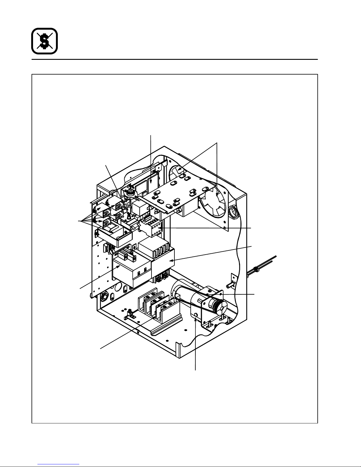
Wartung
Lage der Komponenten
Obergrenze--Reset--- Taste
Steuerungs--stromversorgung
und
Relaisvorrichtung
MT1828E
Motorantriebsplatine
Lüfter
Gebläsemotor--Kontaktgeber
Heiz--element--Kontaktgeber
Netzanschluß
Abwärtstransformator
Antriebsriemen
Förderbandmotor
Abbildung 13
66
Page 68

MÖGLICHE URSACHE(N) EMPFOHLENE MASSNAHMEN
SYMPTOM: Gebläsmotor(en) läuft bzw. laufen nicht
S
Gebläsesteuerung abgeschaltet
S
Ofen ohne Strom
S
Motorsicherungen durchgebrannt
S
Sicherung des Steuerungsschaltkreises
durchgebrannt
SYMPTOM: Brenner funktioniert nicht oder Elemente heizen nicht
S
Steuerung ausgeschaltet
S
Gebläsemotor(en) läuft bzw. laufen nicht
S
Ofen nicht über Umgebungstemperatur
eingestellt.
S
Manuelles Gasventil geschlossen
(nur Gasmodelle)
S
Gebläse einschalten
S
Hauptsicherungen oder Wiedereinschaltschutzschalter ersetzen
S
Sicherungen ersetzen
S
Sicherungen ersetzen
S
Steuerung einschalten
S
Steuerungsschalter und/oder Sicherungen
überprüfen
S
Auf gewünschte Temperatur eingestellt
S
Ventil öffnen
Wartung
Fehlerbehebung
SYMPTOM: Ofen erreicht nicht gewünschte Temperatur
S
Gasdruck ist zu niedrig (nur Gasmodelle)
S
Gebläsesteuerung abgeschaltet
S
Ofen ohne Strom
S
Gebläsemotor(en) läuft bzw. laufen nicht
SYMPTOM: Förderband läuft nicht
S
Gebläsesteuerung abgeschaltet
S
Sicherung des Steuerungsschaltkreises
durchgebrannt
S
Band ist an einem Gegenstand im Ofen
hängengeblieben
WARNUNG!!
Stecken Sie vor Reinigungs-- und Wartungsarbeiten stets den Stromstecker aus.
S
Wenden Sie sich an einen lokalen Gastechniker
S
Steuerung einschalten
S
Hauptsicherungen ersetzen
S
Steuerungsschalter und/oder Sicherungen
überprüfen
S
Steuerung einschalten
S
Sicherungen ersetzen
S
Ofen abschalten, Band lösen und Problem
beheben
67
Page 69

Serie MT1828
Forno a convogliatore
Manuale d’uso
68
Page 70

Installazione
Specifiche del forno
SPECIFICHE MT1828G/AB MT1828E/AA
Larghezza nastro 46 cm (18”)
Lunghezza zona cottura 71 cm (28”)
Area cottura 0,34 m2(3,7 piedi quadrati)
Dimensioni (unità singola) 104 cm x 89 cm x 46 cm (41” x 35” x 18”)
Tem per atu r a op era tiv a
max.
Gioco prodotto 9,5 cm (3,75”)
Calore immesso max. 11,7 kW/ora (40.000 BTU/ora ) 11,1 kW/ora
Alimentazione elettrica 230 VAC, 1Φ, 50Hz, 3 fili, 15 amp 230/400 VAC, 3Φ, 50Hz, 5 fili, 17 amp
Alimentazione gas Vedi tabella a pag. 74 Nessuno
315 _C (600_F)
69
Page 71

Installazione
Fornitura e collocazione
FORNITURA E CONTROLLO
Tutti i forni Blodgett vengono forniti all’interno di
contenitori in modo da evitare danni. Al momento
della consegna del forno eseguire i controlli di seguito descritti.
D
Controllare che il contenitore di spedizione non
presenti danni esterni. Qualunque danno evidente deve essere registrato sulla bolla di consegna che deve essere firmata dal conducente.
D
Disimballare il forno e controllare che non vi siano danni interni. Il trasportatore accetterà reclami per danni non evidenti se questi saranno notificati entro quindici giorni dalla consegna e se
il contenitore è stato conservato ai fini di un controllo.
La Blodgett Oven Company non si assume responsabilità per alcuna perdita o danno subiti
durante il trasporto. Il trasportatore si assume
la piena responsabilità di consegnare la merce
in buono stato al momento dell’accettazione
della spedizione. Tuttavia, siamo pronti ad assistervi qualora si renda necessario archiviare
un reclamo.
COLLOCAZIONE DEL FORNO
Per soddisfare l’utilità per l’operatore ed il rendimento del forno stesso, s i deve pianificare bene
quale sia la sede idonea per l’installazione del forno.
D
Posizionare il forno a una distanza di almeno 5
cm dalla parete posteriore e di 50 cm dalla parete laterale.
D
Installare il forno in una sede adeguatamente
ventilata.
D
Collocare il forno sotto una cappa d’aerazione,
conformemente agli standard di installazione
locali e nazionali.
D
Posizionare il forno in modo da garantire l’accessibilità della spina di alimentazione.
A questo punto s i può portare il forno nella sua sede di installazione. Confrontare l’elenco che segue con i dati riportati in Figura 1 per accertarsi
chesianostatiricevutituttiipezzi.
Descrizione pezzo
Q.tà
Corpo principale forno 1
Gruppo nastro trasportatore 1
Vaschette di raccolta 2
Pacchetti contenenti articoli metallici 2
Fermo prodotto 1
Gruppo convogliatore
(illustrato senza nastro)
Fermo
prodotto
Vaschette di raccolta
Figura 1
70
Page 72

Installazione
Gruppo forno
NOTA: questo dispositivo deve essere installato
in conformità con la normativa vigente e
usato solo in uno spazio ben-ventilato.
Leggere attentamente le istruzioni prima
di installare e utilizzare il dispositivo. L’installazione deve essere eseguita esclusivamente da un installatore qualificato.
GAMBE
1. Disimballare il forno.
2. Appoggiareilfornosulsuoretro.Avvitarele
quattro gambe negli appositi fori di montaggio
posti sul fondo della camera del forno.
3. Serrare il dado esagonale in cima ad ogni
gamba.
4. Sollevare il forno perpendicolarmente e appoggiarlo sulle gambe.
Fondo del
forno
Figura 2
5. Nei modelli a gas, collegare una staffa di contenimento.
Gamba
Limite sup.
Incastellatura
di sostegno
dell’incastellatura
Mensola
Figura 3
SOVRAPPOSIZIONE DEI FORNI
1. Appoggiare il forno superiore sul suo retro. Installare i quattro perni di allineamento nei fori
di montaggio appositamente previsti sul fondo del forno.
2. Sollevare con attenzione il forno superiore dal
pallet e posizionarlo su quello inferiore. Assicurarsi che i perni di allineamento vengano
correttamente inseriti nei fori di montaggio appositamente previsti in cima al forno inferiore.
INCASTELLATURA DEL FORNO CON ROTELLE
1. Fissare le gambe all’incastellatura di sostegno utilizzando, per ciascuna, una rondella
elastica e un dado. NON serrare completamente.
2. Posizionare la mensola tra le gambe del forno,
orientando la superficie liscia verso il limite superiore dell’incastellatura. Allineare la mensola con i fori di montaggio in ogni gamba. Fissare la mensola alle gambe con dadi e bulloni.
3. Serrare i bulloni posizionati al punto 1.
4. Collocare il forno sull’incastellatura di sostegno. Da sotto, bullonare il forno all’incastellatura.
Perno di allineamento
Forno inferiore
Figura 4
71
Page 73

Installazione
Gruppo forno
CONVOGLIATORE
1. Far scorrere il gruppo convogliatore nella scanalatura di sinistra finché il rocchetto non sarà
penetrato nella scatola di comando. Vedi
Figura 5.
2. Installarela catena di trasmissione sul motore,
quindi avvolgerla sulla puleggia del gruppo
convogliatore.VediFigura 6. Spingere il gruppo convogliatore per tendere la catena.
NOTA: Per invertire la direzione del motore di tra-
smissione (se necessario), scambiare i
poli A1 e A2. Vedi Figura 7.
AVVERTENZA!!
Scollegare il cavo di alimentazione del
forno prima di invertire la polarità del motore di trasmissione.
W
AC
AC
L2 L1
A1 A2 A3
W
V
INT
TERRA
MOTORE DC
Y OR BL
S2
S3
CONTROLLO
S1
VELOCITÀ
Figura 5
Figura 6
Figura 7
DI RACCOLTA
1. Installare le vaschette di raccolta sotto le due
estremità del convogliatore.
Figura 8
72
Page 74

Installazione
Collegamenti alle u tenze
COLLEGAMENTI AL GAS (se applicabili)
Collegare il forno alla linea del gas idoneo seguendo gli standard d’installazione locali e nazionali.
Preparazione dell’apparecchiatura per altri tipi
di ga s
1. Rimuovere il portello della scatola di comando
eilcopricatena.
2. Estrarre dal forno tutto il sistema di tubatura e
il gruppo bruciatore.
3. Rimuovere le quattro viti che fissano il ventilatore e il copricatena alla flangia di montaggio
del bruciatore. Smontare il ventilatore e il copricatena dal bruciatore.
4. Svitare il sistema di tubatura nella sezione
d’ingresso della valvola del gas.
5. Solo per la Francia e il Belgio --- È ne c e s s a rio sostituire il rubinetto di regolazione nella
sezione d’ingresso della valvola del gas. Nei
forni a metano, tale rubinetto di regolazione
sarà dotato di un limitatore di efflusso interno
di 3,2mm.
Per passare dal metano al propano/butano,
sarà necessario togliere il rubinetto di regolazioneconlimitatoredi efflusso e sostituirlo con
unochenesiaprivo.
Per passare dal propano/butano al metano,
sarà necessario togliere il rubinetto di regolazione privo di limitatore di efflusso e sostituirlo
con uno che ne sia dotato. Orientare il rubinetto di regolazionein modo che il limitatore di efflusso sia vicino alla valvola e l’estremità aperta si trovi accanto alla curva del tubo.
6. Svitare la valvola del gas e il resto del sistema
di tubatura fino al giunto d’ingresso nel tubo
del bruciatore, quindi svitare il giunto stesso.
7. Rimuovere la boccola isolante che contiene i
rilevatori di accensione e di fiamma.
8. Afferrare la parte frontale dell’orifizio e, contemporaneamente, fare pressione sul raccordo in cima al tubo del bruciatore. Estrarre l’orifizio dalla parte frontale del tubo del
bruciatore.
NOTA: assicurarsi di non perdere l’anello di-
stanziatore che avvolge il rubinetto di
regolazione nella sezione d’ingresso
dell’orifizio,in quantoverràriutilizzato.
9. Rimuovere gli elettrodi dei rilevatori di accensione e di fiamma dall’orifizio. Reinstallarli nella
stessa posizione nel nuovo orifizio .
10. Per rimontare il bruciatore, invertire la procedura appena descritta.
NOTA: nel ricollegare i raccordi del sistema
di tubatura, assicurarsi di reinstallare
l’anello distanziatore e di applicare
materiale di tenuta sulle filettature.
11. Reinstallare la valvola del gas e il gruppo bruciatore all’interno del forno.
Vite di regolazione
pressione gas
Scollegare qui la
tubatura del gas
Tappo pressione
Viti di montaggio
ventilatore
Scollegare qui la
tubatura del gas
Boccola isolante
per i rilevatori
di accensione
e di fiamma
Staffa di
montaggio
copricatena
Figura 9
73
Page 75

Installazione
/
A
G20/G2520/25Regolatoredipressione
1,40N/A11,7metano
Collegamenti alle u tenze
Tipo di
gas
Pressione
in entrata
mbars
Pressione bruciatore
mbars
Diametro
iniettore
mm
Apertura
aria
mm
Fornitura standard
Valore kW (H
G25 25 12 1,40 N/A 11,7 metano
G20 20 8,0 1,40 N/A 11,7 metano
G20/G25 20/25 Regolatore dipressione 1,40 N
11,7 metano
completamente avvitato
G30 30/50 6 1,1 N/A 11,7 butano
G31 30/37/50 8 1,1 N/A 11,7 propano
COLLEGAMENTI ELETTRICI
NOTA: i collegamentielettrici devono essereese-
guiti esclusivamente da un installatore
qualificato.
NOTA: i collegamenti elettricidevono esserecon-
formiaicodicilocalienazionali.
È richiesto un aggancio per il cavo di alimentazione. L’installatore deve fornire un rivestimento isolante per il cavo d’alimentazione che sia conforme
a tutti gli standard d’ installazione localie nazionali.
Per i modelli a gas
NOTA: I modelli a gas dispongono di un’unità di
Collegareiconnettoridegliaspiratori1e2.Vedi
Figura 10.
Collegare fase, neutro e terra.
Per i modelli elettrici
Collegare il forno a un alimentatore separato da
230V, 50 Hz con una connessione rigida e un interruttore. L’interruttore deve scollegare tutti i poli,
compreso quello neutro, con una separazione di
contatto pari almeno a 3 mm.
Collegare L1, L2, L3, neutro e terra.
la fase e il neutro dovessero commutarsi,
l’unità di controllo attiverà un blocco.
controllo bruciatoresensibile alla fase. Se
)
s
L3
L2
L1
N
Connettore
Blodgett
1 --- Solenoide di comando bruciatore
2 --- Regolatore pressione aria
N
L
Connettore
1
2
Figura 10
74
Ventola
A2
2-4-92
s
2
A1
Relè A
1
Page 76

FUNZIONAMENTO
NOTA: Le procedure inerenti al funzionamento
del fornodevono essere espletateesclusivamente da personale qualificato.
Per accendere il forno:
1. Aprire la valvola manuale del gas portandola
in posizione ON (solo per i modelli a gas).
2. Tenere premuto il tasto ON/OFF (2).
3. Sul display lampeggerà la scritta WAIT LOW
SET TIME mmss.
4. La spia HEAT (4) resta accesa mentre il forno
si scalda fino a raggiungere la temperatura impostata.
NOTA: Se, attivando il forno, il bruciatore non si
accende direttamente, lampeggerà la
spia di allarme. Premere il tasto RESET per
riavviare il bruciatore (solo modelli a gas).
NOTA: se il forno non dovesse accendersi dopo
vari tentativi, contattare un installatore qu alificato.
Funzionamento
Computer per la cottura
Per visualizzare il tempo di cottura:
1. Premere il tasto TIME (8). Il LED del tasto si accenderà e sul display lampeggerà la scritta
SET TIME mmss.
Per visualizzare la temperatura attuale del forno:
1. Premereil tasto ACT TEMP (6). Il LED del tasto
si accenderà e sul display si leggerà la scritta
ACTUAL nnnn_C.
Per visualizzare la temperatura impostata:
1. Premere il tasto SET TEMP (6). Il LED del tasto
si accenderà e sul display lampeggerà la scritta SET TEMP nnnn_ C.
Per spegnere il forno:
1. Premere il tasto ON/OFF (2). Le ventole di raffreddamento resteranno in funzione finché il
forno non si sarà raffreddato.
2. Chiudere la valvola manuale del gas portandola in posizione OFF (solo per i modelli a
gas).
10
1
56789
4
Figura 11
75
2
3
Page 77

Funzionamento
Computer per la cottura
PROCEDURE DI PROGRAMMAZIONE
Programmazione del tempo di cottura:
1. Premere il tasto PROGRAM/ENTER (9).
2. Premere il tasto TIME (8). Sul display si legge:
PROG-?SETTIME-?____.
3. Utilizzare il tastierino NUMERICO (3) per impostare il tempo di cottura desiderato. In caso
di errore, premere il tasto CLEAR (5) e re-inserire il numero.
4. Premere due volte il tasto PROGRAM/ENTER
(9) per salvare il nuovo tempo di cottura.
Programmazione della temperatura di cottura
1. Premere il tasto PROGRAM/ENTER (9).
2. Premere il tasto SET TEMP (6). Sul display si
legge: PROG-?SETTEMP-?____C.
3. Usare il tastierino NUMERICO (3) per impostare la temperatura desiderata. In caso di errore, premere il tasto CLEAR (5) e re-inserire
il numero.
4. Premere due volte il tasto PROGRAM/ENTER
(9) per salvare la nuova temperatura di cottu ra.
76
Page 78

Manutenzione
Pulizia e sostituzione componenti
PULIZIA
NOTA: NON spruzzare il forno con un getto d’ac-
qua.
Manutenzione giornaliera:
1. Estrarreepulirelevaschettediraccolta.
2. Pulire il nastro trasportatore con una spazzola.
Ogni tre mesi:
1. Pulire le calotte di protezione delle ventole assiali.
Ogni 6 mesi:
1. Estrarre il nastro trasportatore e le guide.
2. Pulire l’interno del forno.
Ogni 12 mesi:
Un addetto autorizzato dalla ditta deve:
1. Pulire il pannello di controllo, la cavità del forno,ilbruciatoreeleventole.
2. Controllare i collegamenti elettrici principali.
3. Controllare il motore di trasmissione. Sostituire le spazzole in carbonio.
4. Pulire e lubrificare la catena di trasmissione.
5. Controllare e regolare la taratura del gas (solo
per i modelli a gas).
SOSTITUZIONE COMPONENTI
Componenti elettrici
1. Chiudere il gas (se applicabile). Disattivare il
collegamento elettrico principale.
2. Rimuovere il coperchio della scatola di comando.
3. Sostituire i componenti difettosi.
4. Riposizionare il coperchio sulla scatola di comando.
5. Riattivare il collegamento elettrico principale.
Riaprire il gas (se applicabile).
Gruppo di controllo gas
NOTA: solo per i modelli a gas.
1. Chiudere il gas. Disattivare il collegamento
elettrico principale.
2. Disconnettere il collegamento al gas su entrambi i lati del gruppo di controllo gas.
3. Sostituireeregolareilcollegamentoalgas.
Controllare che non vi siano perdite.
4. Riattivare il collegamento elettrico principale.
Riaprire il gas.
Estrazione del bruciatore
NOTA: solo per i modelli a gas.
1. Chiudere il gas. Disattivare il collegamento
elettrico principale.
2. Disconnettere il collegamento al gas.
3. Rimuovere le quattro viti dalla piastra di supporto del bruciatore. Estrarre il bruciatore.
4. Sostituire l’iniettore pilota, se necessario.
5. Reinstallare il bruciatore.
6. Riattivare il collegamento elettrico principale.
Riaprire il gas.
Ventole di raffreddam ento
1. Chiudere il gas (se applicabile). Disattivare il
collegamento elettrico principale.
2. Rimuovere il pannello posteriore del forno. Rimuovere il rivestimento isolante, se necessario.
3. Smontare e sostituire le ventole difettose.
4. Reinstallare il rivestimento isolante e il pannello posteriore del forno.
5. Riattivare il collegamento elettrico principale.
Riaprire il gas (se applicabile).
Camera di combustione
NOTA: solo per i modelli a gas.
1. Chiudere il gas.
2. Smontare la piastra di rinforzo e il rivestimento
isolante della camera di combustione.
3. Pulire la camera di combustione.
4. Reinstallare il rivestimento isolante e la piastra
di rinforzo.
5. Riaprire il gas.
Componenti del pannel lo operativo
1. Chiudere il gas (se applicabile). Disattivare il
collegamento elettrico principale.
2. Rimuoverelevitidifermodelpannellosulfondo del forno. Estrarre il pannello operativo tramite scivolamento.
3. Sostituire il componente difettoso.
4. Reinstallare il pannello operativo.
5. Riattivare il collegamento elettrico principale.
Riaprire il gas (se applicabile).
77
Page 79

Manutenzione
Disposizione dei componenti
Piastra di
trasmissione a motore
Pulsante di ripristino
alta temperatura
MT1828G
Ventole di raffreddamento
Pressostato
flusso d’aria
Pressostato
flusso d’aria
Comando
accensione
bruciatore
Collegamento
all’alimentazione
Gruppo ventilatore
del bruciatore
Catena di trasmissione
Valvola di
regolazione gas
Motore nastro trasportatore
Figura 12
78
Page 80

Pulsante di ripristino
alta temperatura
Manutenzione
Disposizione dei componenti
MT1828E
Piastra di
trasmissione a motore
Ventole di raffreddamento
Gruppo di controllo
alimentazione
erelè
Contattore
elemento
riscaldante
Collegamento
all’alimentazione
Contattore motore
del ventilatore
Trasformatore
abbassatore
Catena di trasmissione
Motore nastro trasportatore
Figura 13
79
Page 81

Manutenzione
Ricerca ed eliminazione dei guasti
CAUSA(E) POSSIBILE(I) RIMEDIO CONSIGLIATO
SINTOMO: il(i) motore(i) del ventilatore non funziona(no).
S
Controllo del ventilatore spento.
S
Forno non alimentato.
S
Fusibili del motore bruciati.
S
Fusibile del circuito di controllo bruciato.
SINTOMO: il bruciatore non brucia o gli elementi non riscaldano.
S
Controllo spento.
S
Il(i) motore(i) del ventilatore non funziona(no).
S
La temperatura impostata per il forno non è su periore alla temperatura ambiente.
S
Valvola del gas manuale chiusa (solo per i modelli a gas).
S
S
S
S
S
S
S
S
Accendere il controllo del ventilatore.
Sostituire i fusibili principali o resettare gli inter-
ruttori.
Sostituire i fusibili.
Sostituire i fusibili.
Accendere il controllo.
Controllarel’interruttore di comando e/o i fusibili.
Impostare la temperatura desiderata.
Aprire la valvola.
SINTOMO: il forno non raggiunge la temperatura desiderata
S
La pressione del gas al forno è troppo bassa (solo per i modelli a gas).
S
Dispositivo di controllo calore disattivato.
S
Forno non alimentato.
S
Il(i) motore(i) del ventilatore non funziona(no).
SINTOMO: il nastro trasportatore non scorre.
S
Dispositivo di comando del nastro disattivato.
S
Fusibile del circuito di controllo bruciato.
S
Nastro agganciato a qualcosa all’interno del forno.
AVVERTENZA!!
Scollegare sempre l’alimentazione elettrica prima di eseguire le operazioni di pulizia e di ma-
nutenzione d el forno.
S
Contattare i rappresentanti dell’ente gas locale.
S
Attivare il dispositivo di controllo.
S
Sostituire i fusibili principali.
S
Controllarel’interruttore di comando e/o i fusibili.
S
Attivare il dispositivo di comando.
S
Sostituire il fusibile.
S
Spegnare il forno, sganciare e risolvere il problema.
80
Page 82

Série MT1828
Forno de Correia
Manual do Utilizador --- Proprietário
81
Page 83

Instalação
Especificações do forno
ESPECIFICAÇÕES MT1828G/AB MT1828E/AA
Largura da correia 46 cm (18”)
Comprimento da zona
de cozedura
Área de cozedura .34 m2(3.7 Pés Quadrados)
Dimensões
(unidade única)
Tem per atu r a de
operação máxima
Distância mínima do
produto
Entrada máxima 11.7 kW/Hora. (40,000 BTU/HORA ) 11.1 KW/hora.
Entrada de energia 230 VAC, 1Φ, 50Hz, 3 fios, 15 Amp 230/400 VAC, 3Φ, 50Hz, 5 fios, 17 amp
Entrada de gás Vertabelanapágina87 Nenhuma
71 cm (28”)
104 cm x 89 cm x 46 cm (41” x 35” x 18”)
315_C (600_F)
9.5 cm (3.75”)
82
Page 84

Instalação
Entrega e localização
ENTREGA E INSPECÇÃO
Todos os fornos Blodgett são enviados em contentores para evitar danos. Aquando da entrega
do seu novo forno:
D
Inspeccione o contentor de envio para ver se
existem danos externos. Qualquer evidência de
dano deve ser anotada no recibo de entrega
que tem de ser assinado pelo condutor.
D
Retire o forno e verifique se tem danos internos.
Os transportadores aceitam danos para danos
escondidos se forem notificados até 15 dias
apósaentregaeseocontentordeenviofor
guardado para inspecção.
A Blodgett Oven Company não pode assumir
responsabilidade por perdas ou danos sofridos no transporte. O transportador assumiu
responsabilidade total pel a entrega em bom
estado quando o envio foi aceite. Estamos, no
entanto, disponíveis para o ajudar caso tenha
de apresentar uma reclamação.
LOCALIZAÇÃO DO FORNO
A colocação bem planeada e apropriada do seu
forno resultará em conveniência a longo prazo para o operador e num desempenho satisfatório.
D
Coloque o forno a pelo menos 5 cm da parede
traseira e a 50 cm da parede lateral.
D
Coloque o forno numa área bem ventilada.
D
Coloque o forno sob um escape, de acordo
com os critérios de instalação nacionais e locais.
D
Posicioneofornodeformaaqueafichadeentrada esteja acessível.
Pode agora mover o forno para o local de instalação. Verifique a lista abaixoFigura 1 para se certificardequetodosositensforamrecebidos.
Descrição das peças
Quantidade
Corpo principal do forno 1
Montagem da correia 1
Tabuleiros de migalhas 2
Embalagens de hardware 2
Calçodoproduto 1
Montagem da correia
(mostrado sem cinto)
Calço
de produto
Tabuleiros de migalhas
Figura 1
83
Page 85

Instalação
Montagem do forno
NOTA: Este aparelho será instalado de acordo
com os regulamentos actuais e usado
apenas num espaço bem- ventilado. Consulte as instruções antes de instalar ou utilizar este aparelho. A instalação só pode
ser feita por um instalador qualificado.
PERNAS
1. Retire o forno da embalagem
2. Deite o forno. Prenda uma perna em cada um
dos quatro buracos na base da câmara do forno.
3. Aperteoparafusonotopodecadaperna.
4. Levanteofornoecoloque---osobreaspernas.
Base do
forno
Perna
Topo do
Encaixe do
suporte
suporte
Prateleira
Figura 3
EMPILHAR OS FORNOS
1. Deiteofornodotopo.Instaleumpinodealinhamento de forno em cada um dos quatro
buracos na base do forno.
2. Levante cuidadosamente o forno do t opo da
palete e coloque---o no forno da base. Certifique---se de que os pinos de alinhamentos estão inseridos nos buracos do topo do forno da
base.
Figura 2
SUPORTE DO FORNO COM RODAS
1. Prenda cada perna ao suporte com um parafuso e uma porca. NÃO aperte totalmente.
2. Coloque a prateleira entre as pernas com a
superfície lisa virada para o topo do suporte.
Alinhe a prateleira com os buracos em cada
perna. Prenda a prateleira a cada perna com
um parafuso com porca e cabeça.
3. Aperte as porcas instaladas no passo1
4. Coloqueo forno no suporte. Prenda o forno ao
suporte a partir da base.
5. Prenda um descanso nos modelos a gás.
Pino de alinhamento
Forno da base
Figura 4
84
Page 86

Instalação
Correia da montagem
DO FORNO
1. Insiraamontagemdacorreianotúnelàes-
querda até que a roda dentada esteja dentro
da caixa de controlo. V er Figura 5
2. Instale a correia de propulsão no motor e de-
pois na roldana da montagem da correia. Ver
Figura 6 Empurre a montagem da correia para trás de forma a apertar a correia.
Figura 5
NOTA: Parainverteradirecçãodomotordepro-
pulsão (se necessário), troque A1 e A2.
VerFigura 7
ADVERTÊNCIA!!
Desligue a energia antes de inverter o
motor de propulsão.
W
AC
AC
L2 L1
A1 A2 A3
W
V
BK
GND
MOTOR DC
Y OU BL
S2
S3
CONTROLO
VELOCIDADE
S1
DE
Figura 7
TABULEIROS DE MIGALHAS
1. Instale os tabuleiros de migalhas em ambas
as extremidades da correia.
Figura 6
Figura 8
85
Page 87

Instalação
Ligações de utilidades
LIGAÇÕES DE GÁS( caso se aplique)
Ligue o forno ao gás com o tipo de gás apropriado
de acordo com os critérios de instalação locais e
nacionais.
Configurar o equipamento para outros tipos de
gás
1. Remova a porta da caixa de controlo e a protecção da correia.
2. Remova toda a canalização de gás e queimador do forno.
3. Remova os quatro parafusos que prendem o
soprador e protecção de correia ao rebordo
de montagem do queimador. Remova o queimador e a protecção da correia do queimador.
4. Desaparafuse a canalização de gás na entrada da válvula de gás.
5. Apenas França e Bélgica --- Te m d e s e alt e rar o bico da entrada da válvula de gás. Em
fornos de gás natural, este bico tem um restri torde3,2mmnointerior.
Para se converter de gás natural para propano/butano, o bico com restritor tem de ser removido e substituído por um bico sem restritor.
Para se converter de propano/butano para
gás natural, o bico sem restritor tem de ser removido e substituído por um bico com restritor. Oriente o bico de forma a que o restritor
esteja perto da válvula e que a parte aberta esteja perto da dobra da canalização.
6. Desaperte a válvula de gás e canalizaçãorestante até (e incluindo) à união em que entra no
tubo do queimador.
7. Remova o ilhó que prende os fios de faísca e
chama.
8. Segure na parte frontal da montagem do orifício enquanto empurra o encaixe no topo do
tubo do queimador. Puxe a montagem de orifícioparaforadafrentedotubodoqueimador.
NOTA: Tenha cuidado para não perder o anel
separador que está à volta do bico na
entradadamontagemdoorifícioporque voltará a ser usado.
9. Remova os eléctrodos de faísca e chama da
montagem do orifício. Volte a instalar na mesma
posição na nova montagem do orifício.
10. Inverta o procedimento para voltar a montar o
queimador.
NOTA: Certifique---se de que instala o anel
espaçador e de que sela a rosca ao
voltar a ligar as canalizações.
11. Volte a instalar a válvula de gás e a montagem
do queimador no forno.
Ajuste
Desligue a
canalização de
gás aqui
Tamp a de
pressão
Parafusos de
montagem do
queimador
da pressão de gás
Suportedemontagem
da protecção de correia
Desligue a
canalização de
gás aqui
Ilhó para
fios de
faísca e chama
Figura 9
86
Page 88

Instalação
Ligações de utilidades
Tipo de
gás
Pressão
de
entrada
Pressãodoqueima-
dor
mbars
Injector
Diâmetro
mm
Abertura de
ar
mm
Distribuição standard
Valor kW (H
mbars
G25 25 12 1,40 N/A 11,7 Gás Nat.
G20 20 8,0 1,40 N/A 11,7 Gás Nat.
G20/G25 20/25 Reguladordepressão
1,40 N/A 11,7 Gás Nat.
totalmente aparafusa-
do
G30 30/50 6 1,1 N/A 11,7 Butano
G31 30/37/50 8 1,1 N/A 11,7 Propano
LIGAÇÕES ELÉCTRICAS
NOTA: A ligação eléctrica só pode ser feita por
um instalador qualificado.
NOTA: A ligação eléctrica tem de estar de acordo
com os códigos nacionais e locais.
É necessário um descanso para o cabo de entrada de energia. O instalador tem de fornecer um
casquilho para o cabo de acordo com todos os
critérios de instalação locais e nacionais.
Para modelos a gás:
NOTA: Os modelos a gás têm uma unidade de
controlo do queimador sensível a fases.
Ligue a ligação à ventoinha de escape 1 e 2. Ver
Figura 10.
Ligue fase + neutro + terra.
Para modelos eléctricos:
Ligue o forno a um grupo separado de 230 V, 50
Hz com ligação rígida e interruptor de circuito. O
interruptor de circuito deve desligar todos os pólos, incluindo o neutro, com uma separaçã o de
contacto de pelo menos 3 mm.
Ligue L1 + L2 + L3 + neutro + terra.
Se a fase e o neutro forem ligados, o controlo bloqueia.
)
S
L3
L2
L1
N
Blodgett
Ligação
1--- Solenóide de controlo do queimador
2–Reguladordapressãodoar
N
L
Ligação
1
2
Figura 10
87
Ventoinha
A2
2
s
2-4-92
A1
Auxiliar A
1
Page 89

Operação
Computador de Cozinha
OPERAÇÃO
NOTA: A operação é restrita a pessoal qualifica-
do.
Para ligar o forno:
1. Rode a válvula de gás manual para LIGADO
(ON). (Apenas em modelos de gás).
2. PrimaemantenhapremidaateclaLIGADO/
DESLIGADO (ON/OFF) (2).
3. O ecrã piscará mostrandoWAIT LOW SET TI-
ME mmss.
4. A luz deQUENTE (4) acender--- se---á enquanto o forno aquece até atingir a temperatura.
NOTA: Se ao iniciar, o queimador não acen-
der directamente, acender ---se---á a
luz de alarme. Prima a maçaneta RESET (RESTAURAR) para reiniciar o
queimador. (Apenas em modelos de
gás).
NOTA: Se o forno não funcionar após várias tenta-
tivas contacte um instalador qualificado.
Para ver a configuração de tempo de cozedura:
1. Prima a tecla TIME (TEMPO) (8). O LED da tecla acender --- s e --- á e o e c r ã m o s t r a r á SET TI-
ME mmss.
Para ver a temperatura real do forno:
1. Prima a tecla ACT TEMP (Temperatura real)
(6). O L E D d a t e c l a a c e n d e r --- se --- á e o e c r ã
mostrará ACTUAL nnnn_C.
Para ver o ponto de configuração da temperatura:
1. Prima a tecla SET TEMP (Configurar Temperat u r a ) ( 6 ) . O L E D d a t e c la a c e n d e r --- s e --- á e o
ecrã mostrará SET TEMP nnnn_C.
Para desligar o forno:
1. Prima a tecla ON/OFF (2). As ventoinhas continuarão em funcionamento até o forno arrefecer.
2. Rode a válvula de gás manual para DESLIGADO (OFF). (Apenas em modelos de gás).
10
1
56789
4
Figura 11
88
2
3
Page 90

PROCEDIMENTOS DE PROGRAMAÇÃO
Programar o tempo de cozedura:
1. Prima a tecla PROGRAM/ENTER (Programa/
Enter) (9).
2. Prima a tecla TIME (TEMPO) (8). O ecrã mostra PROG-?SETTIME-?____.
3. UseasteclasNUMÉRICAS(3)parainseriro
tempo de cozedura desejado. Se se enganar,
prima a tecla CLEAR (Apagar) (5) e volte-a inserir o número.
4. Prima tecla PROGRAM/ENTER (9) duas vezes
para guardar o novo tempo.
Operação
Computador de Cozinha
Programar a temperatura:
1. Prima a tecla PROGRAM/ENTER (9).
2. Primaa tecla SET TEMP (Configurar Temperatura) (6). O ecrã mostra PROG-? SET TEMP-?
____C.
3. UseasteclasNUMÉRICAS(3)parainseriro
ponto de configuração da temperatura desejado. Se se enganar, prima a tecla CLEAR
(Apagar) (5) e volte-a inserir o número.
4. Prima tecla PROGRAM/ENTER (9) duas vezes
para guardar a nova temperatura.
89
Page 91

Manutenção
Trocar e limpar peças
LIMPEZA
NOTA: NÃOusarjactodeáguanoforno.
Diariamente
1. Retire e limpe os tabuleiros de migalhas.
2. Limpe a correia com uma escova.
De 3 em 3 meses
1. Limpeasprotecçõesdasventoinhasaxiais
De 6 em 6 meses
1. Retire a correia e as protecções.
2. Limpe o interior do forno.
De 12 em 12 meses
Umapessoaautorizadapelafábricadeve:
1. Limpar o painel de controlo, cavidade do forno, queimador e ventoinhas.
2. Verificarasprincipaisligaçõeseléctricas.
3. Verificar o motor de propulsão. Trocar as escovas de carvão.
4. Limparelubrificaracorreiadepropulsão.
5. Verificareajustarogás.(Apenasemmodelos
de gás).
TROCA DE PEÇAS
Componentes eléctricos
1. Feche o gás (caso se aplique). Desligue a ligação eléctrica principal.
2. Retire a tampa da caixa de controlo.
3. Troque os componentes com defeito.
4. Volte a colocar a tampa da caixa de controlo.
5. Ligue a ligação eléctrica principal. Ligue o gás
(caso se aplique).
Combinação do controlo de gás
NOTA: Apenas em modelos de gás.
1. Feche o gás. Desligue a ligação eléctrica principal.
2. Retire a ligação de gás em ambos os lados da
combinação de controlo.
3. Verifiqueeajustealigaçãodegás.Verifique
se existem fugas de gás.
4. Ligue a ligação eléctrica principal. Ligue o
gás.
Retirar o queimador
NOTA: Apenas em modelos de gás.
1. Feche o gás. Desligue a ligação eléctrica principal.
2. Retire a ligação de gás.
3. Retire os quatro parafusos da place de montagem do queimador. Retire o queimador.
4. Troque o piloto se necessário.
5. Volte a instalar o queimador.
6. Ligue a ligação eléctrica principal. Ligue o
gás.
Ventoinhas de arrefecimento
1. Feche o gás (caso se aplique). Desligue a ligação eléctrica principal.
2. Retireopaineltraseirodoforno.Retireoisolamento se necessário.
3. Desligue e troque as ventoinhas com defeito.
4. Volte a instalar o isolamento e o paineltraseiro
do forno.
5. Ligue a ligação eléctrica principal. Ligue o gás
(caso se aplique).
Câmara de combustão
NOTA: Apenas em modelos de gás.
1. Feche o gás.
2. Remova a tampa e isolamento da câmara de
combustão.
3. Limpe a câmara de combustão.
4. Volte a instalar o isolamento e a tampa.
5. Ligue o gás.
Componentesdopaineldeoperação
1. Feche o gás (caso se aplique). Desligue a ligação eléctrica principal.
2. Retire os parafusos localizados na base do
forno que seguram o controlo. Retire o painel
de operação deslizando ---o.
3. Troque o componente com defeito.
4. Volte a instalar o painel de operação.
5. Ligue a ligação eléctrica principal. Ligue o gás
(caso se aplique).
90
Page 92
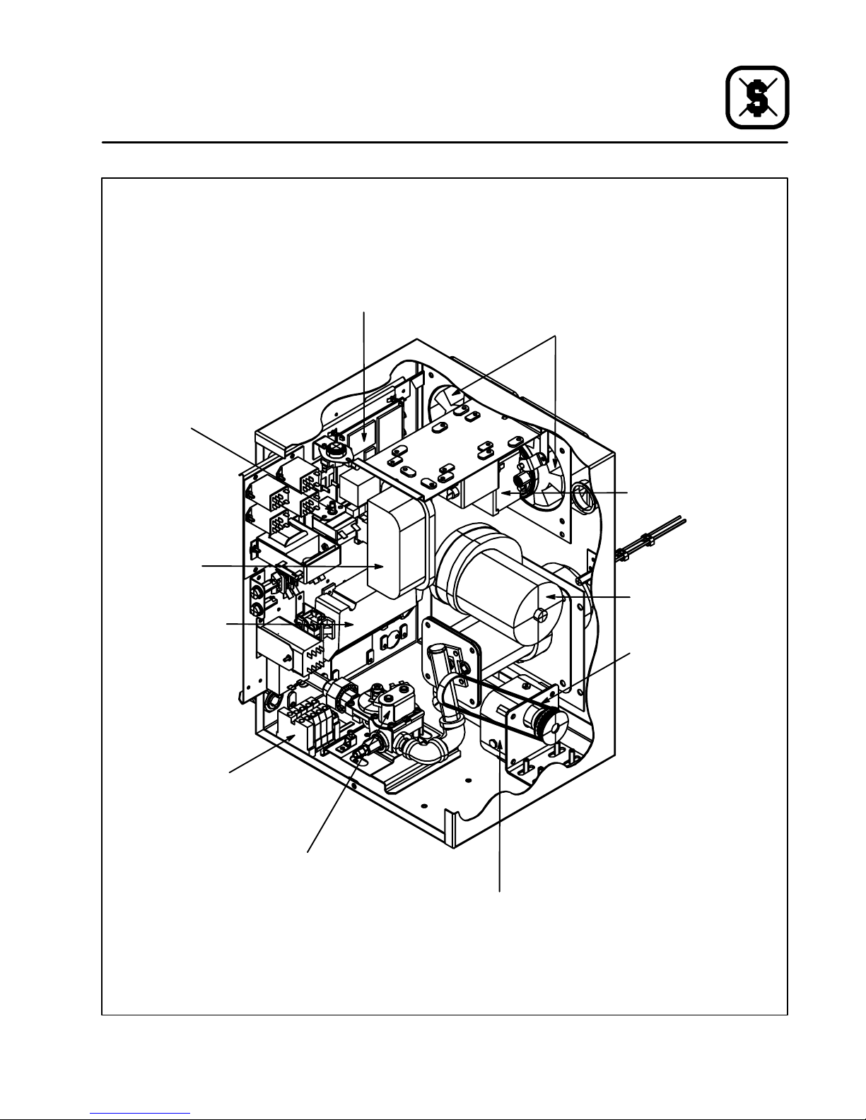
Botão para restaurar
limite máximo
Manutenção
Localização dos componentes
MT1828G
Quadro do motor
de propulsão
Ventoinhas de arrefecimento
Interruptorde pressão do
fluxo de ar
Interruptor de
pressão do
fluxo de ar
Controlo
de ignição d o
queimador
Ligação da
fontedeenergia
Montagem da saída
de gás do queimador
Correia de propulsão
Válvula reguladora de gás
Motor de propulsão da correia
Figura 12
91
Page 93

Manutenção
Localização dos componentes
Quadro do motor
de propulsão
Botão para restaurar
limite máximo
MT1828E
Ventoinhas de arrefecimento
Montagem da
entrada
de energia motor
auxiliar
do controlo
Contacto
do elemento de
aquecimento
Ligação da entrada de
energia
Contacto do
motor do soprador.
Transformador
para redução
Correia de propulsão
Motor de propulsão da correia
Figura 13
92
Page 94

CAUSA(S) POSSÍVEL(EIS) SOLUÇÃO SUGERIDA
SINTOMA: O(s) motor(es) do soprador não estão a funcionar.
S
Controlo do soprador desligado.
S
O forno não recebe energia.
S
Fusíveis do motor queimados.
S
Fusíveldocircuitodecontroloqueimado.
SINTOMA: O queimador não acende ou os elementos não aquecem
S
Controlo desligado
S
O(s) motor(es) do soprador não estão a funcionar.
S
Ofornonãoestáconfiguradoacimadatemperatura ambiente
S
Válvula manual de gás fechada (apenas em modelos a gás)
S
Ligue o soprador
S
Troqueos fusíveis principais ou restaure os interruptores
S
Troque os fusíveis
S
Troque os fusíveis
S
Ligue o controlo
S
Verifique o interruptor do controlo e/ou fusíveis
S
Ponha na temperatura desejada
S
Abraaválvula
Manutenção
Resolução de problemas
SINTOMA: O forno não atinge a temperatura desejada
S
A pressão de gás no forno é demasiado baixa
(apenas em modelos a gás)
S
Controlo de calor desligado.
S
O forno não recebe energia.
S
O(s) motor(es) do soprador não estão a funcionar.
SINTOMA: Correia não anda
S
Controlo da correia desligado.
S
Fusíveldocircuitodecontroloqueimado.
S
A correia está presa em algo no forno
ADVERTÊNCIA!!
Desligue sempre a energia antes de limpar ou fazer a manutenção do forno.
S
Contacte os representantes locais de gás
S
Ligue o controlo
S
Troque os fusíveis principais
S
Verifique o interruptor do controlo e/ou fusíveis
S
Ligue o controlo
S
Troque o fusível
S
Desligeoforno,solteeresolvaoproblema
93
Page 95

Norno del transportador
Serie MT1828
Manual del operario
94
Page 96

Instalación
Especificaciones del horno
ESPECIFICACIONES MT1828G/AB MT1828E/AA
Anchuradelabanda 46 cm (18”)
Longitud de zona de
cocción
Superficie de cocción 0,34 m2(3,7 pies cuadrados)
Dimensiones
(unidad individual )
Máxima temperatura
de funcionamiento
Holgura del producto 9,5 cm (3,75”)
Potencia máxima 11,7 kW/h (40.000 BTU/h) 11,1 KW/h
Ten s ió n de
alimentación
Suministro de gas Véase la tabla de la página 100 No procede
71 cm (28”)
104 cm x 89 cm x 46 cm (41” x 35” x 18”)
315_C (600_F)
230 VCA, 1Φ, 50 Hz, 3 hilos, 15 A 230/400 VCA, 3Φ, 50 Hz, 5 hilos, 17 A
95
Page 97

Instalación
Entrega y emplazamiento
ENTREGA E INSPECCIÓN
Todos los hornos Blodgett se envían en contenedores que evitan su deterioro. A la recepción de
un horno nuevo:
D
Compruebe si existen daños externos en el
contenedor del envío. Cualquier daño observado deberá anotarse en el albarán de entrega,
que deberá firmar el transportista.
D
Desembale el horno y compruebe si presenta
daños internos. Los transportistas aceptan reclamaciones por daños ocultos siempre que se
notifiquen en los quince días siguientes al envío
yseconserveelembalajeparasuinspección.
Blodgett Oven Company declina toda responsabilidad por daños o pérdidas sufridos durante el transporte. Al aceptar el envío, el transpor tista asume l a plena responsabilidad de
entregarlo en buen estado. No obstante, si resulta necesario le ayudaremosa presentar una
reclamación.
EMPLAZAMIENTO DEL HORNO
El emplazamiento del horno en un lugar adecuado y bien planificado redunda en un funcionamiento satisfactorio a largo plazo y una mayor comodidad del operario.
D
Coloque el horno a una distancia de al menos
5 cm respecto de la pared trasera, y de 50 cm
respecto de la pared lateral.
D
Coloque el horno en una zona bien ventilada.
D
Sitúe el hornobajo una campana de extracción,
de conformidad con las normas de instalación
locales y nacionales.
D
Sitúe el horno de manera que el cable de alimentación resulte accesible.
Coloque el horno en su lugar de instalación. Compruebe la lista siguiente, junto con la Figura 1 para
asegurarse de que ha recibido todos sus componentes.
Descripción de la pieza
Unid.
Cuerpo principal del horno 1
Bloque de la banda transportadora 1
Bandejas colectoras 2
Paquetes de componentes 2
Tope de productos 1
Bloque del transportador
(se muestra sin la banda)
Tope de
productos
Bandejas colectoras
Figura 1
96
Page 98

Instalación
Montaje del horno
AVISO: Este aparato debe instalarse de conformi-
dad con la normativa en vigor y utilizarse
exclusivamenteenun lugar bien ventilado.
Consulte las instrucciones antes de instalar y utilizar el aparato. La instalación sólo
puede ser realizada por un instalador cualificado.
PATAS
1. Extraiga el horno del cajón de embalaje.
2. Apoye el horno sobre su trasera. Atornille una
pata en cada uno de los cuatro orificios situados bajo la cámara del horno.
3. Apriete la tuerca hexagonal situada en el extremo de cada una de las patas.
4. Levante el horno y colóquelo de forma que
descanse sobre sus patas.
Cara inferior del
horno
Figura 2
5. En los modelos de gas, instale un enganche
para cable de seguridad.
Pata
Parte superior
Marco
del carro
del carro
Entrepaño
Figura 3
MONTAJE APILADO DE HORNOS
1. Apoye sobre su trasera el horno superior. Inserte una espiga de alineación en cada uno
de los cuatro orificios situados en la cara inferior del horno.
2. Con cuidado, levante de su palet el horno superior y colóquelo sobre el horno inferior. Asegúrese de que las espigas de alineación se introducen en los orificios de la cara superior del
horno inferior.
INSTALACIÓN DEL HORNO EN UN CARRO
CON RUEDAS GIRATORIAS
1. Sujete cada una de las patas al marco empleando una tuerca y una arandela. NO las
apriete por completo.
2. Inserte el entrepaño entre las patas, con la
parte lisa mirando al marco. Ponga el entrepa ño en línea con los orificios de las patas. Fije
el entrepaño a las patas insertando en cada
orificio una tuerca y un tornillo.
3. Apriete los tornillos instalados en el paso 1.
4. Coloque ahora el horno sobre el carro que ha
montado. Atorníll el o a las patas desde debajo.
Espiga de alineación
Horno inferior
Figura 4
97
Page 99

Instalación
Montaje del horno
TRANSPORTADOR
1. Inserte el bloque del transportador en el túnel
situado a mano izquierda, hasta que el piñón
se introduzca en el cajetín de control. Véase
la Figura 5.
2. Instale la correa de transmisión: primero en el
motory después alrededor de la polea del bloque del transportador. Véase la Figura 6. Empuje el bloque del transportador para tensar
la correa.
AVISO: Para invertir el sentido de giro del motor (si
resulta preciso), intercambie las conexiones A1 y A2. Véase la Figura 7.
¡ATENCIÓN!
Antes de invertir el sentido de giro del mo-
tor, desconecte el suministro eléctrico.
Blc.
CA
CA
L2 L1
A1 A2 A3
Blc.
Viol.
Negr.
TIERRA
MOTOR CC
Am.Nar. Azul
S2
S3
CONTROL DE
VELOCIDAD
S1
Figura 7
Figura 5
Figura 6
BANDEJAS COLECTORAS
1. Instale las bandejas colectoras debajo de cada uno de los extremos del transportador.
Figura 8
98
Page 100

Instalación
Conexiones con líneas de s ervicio
CONEXIONES DE GAS (si proceden)
Conecte el horno a una línea de gas del tipo adecuado, de acuerdo con las normas de instalación
locales y nacionales.
Conversión del aparato a otros tipos de gas
1. Desmonte la tapa del cajetín de control y el
protectordelacorrea.
2. Desmonte del horno la tubería de gas y el bloque del quemador.
3. Extraiga los cuatro tornillos que fijan el soplante y el protector de la correa a la brida de montaje del quemador. Desmonte del quemador
el soplante y el protector de la correa.
4. Desenrosque la tubería de gas situada en el
lado de entrada de la válvula de gas.
5. Sólo para Francia y Bélgica:Espreciso
cambiar el tubo roscado de unión situado a la
entradadelaválvuladegas.Parahornosde
gas natural, este tubo de unión deberá tener
en su interior un limitador de 3,2 mm.
Para convertir un horno de gas natural a propano o butano, es preciso desmontar el tubo
roscado de unión con limitador y reemplazarlo por un tubo roscado de unión sin limitador.
Para convertir un horno de propano o butano
a gas natural, es preciso desmontar el tubo
roscado de unión sin limitador y reemplazarlo
por un tubo roscado de unión con limitador.
Coloque el tubo de unión de manera que el
extremo estrecho del limitador quede del lado
de la válvula y el extremo ancho del lado del
codo de la tubería.
6. Desenrosque la válvula de gas y el tramo de
tubería restante, incluido el acoplamiento de
entrada al tubo del quemador.
7. Desmonteel manguitoque protege los cables
de detección de chispa y llama.
8. Sujete el bloque de inyección y, al mismo
tiempo, empuje hacia abajo el acoplamiento
situadosobre el tubo del quemador. Separe el
bloque de inyección del tubo del quemador.
AVISO: No pierda el aro espaciador situado
en el tubo roscado, a la entrada del
bloque inyector, porque se reutiliza.
9. Desmonte del bloque de inyección los electrodos de detección de chispa y llama. Vuelva a
instalarlos, en la misma posición, en el nuevo
bloque inyector .
10. Siga los pasos anteriores en orden inverso para volver a montar el quemador.
AVISO: No olvide volver a colocar el aro espa-
ciador. Cuando vuelva a conectar los
tramos de tubería, utilice un producto
sellante para roscas.
11. Vuelvaainstalarlaválvuladegasyelbloque
del quemador en el horno.
Ajuste de la presión de gas
Desconecte la tubería
de gas por aquí
Boquilla de
presión
Tornillos de
montaje del soplante
Desconecte la
tubería de gas por aquí
Manguito
protector de
los cables
detectores de
chispa y llama
Placa de montaje del
protector de la correa
Figura 9
99
 Loading...