

Page 1
BLAUPUNKT
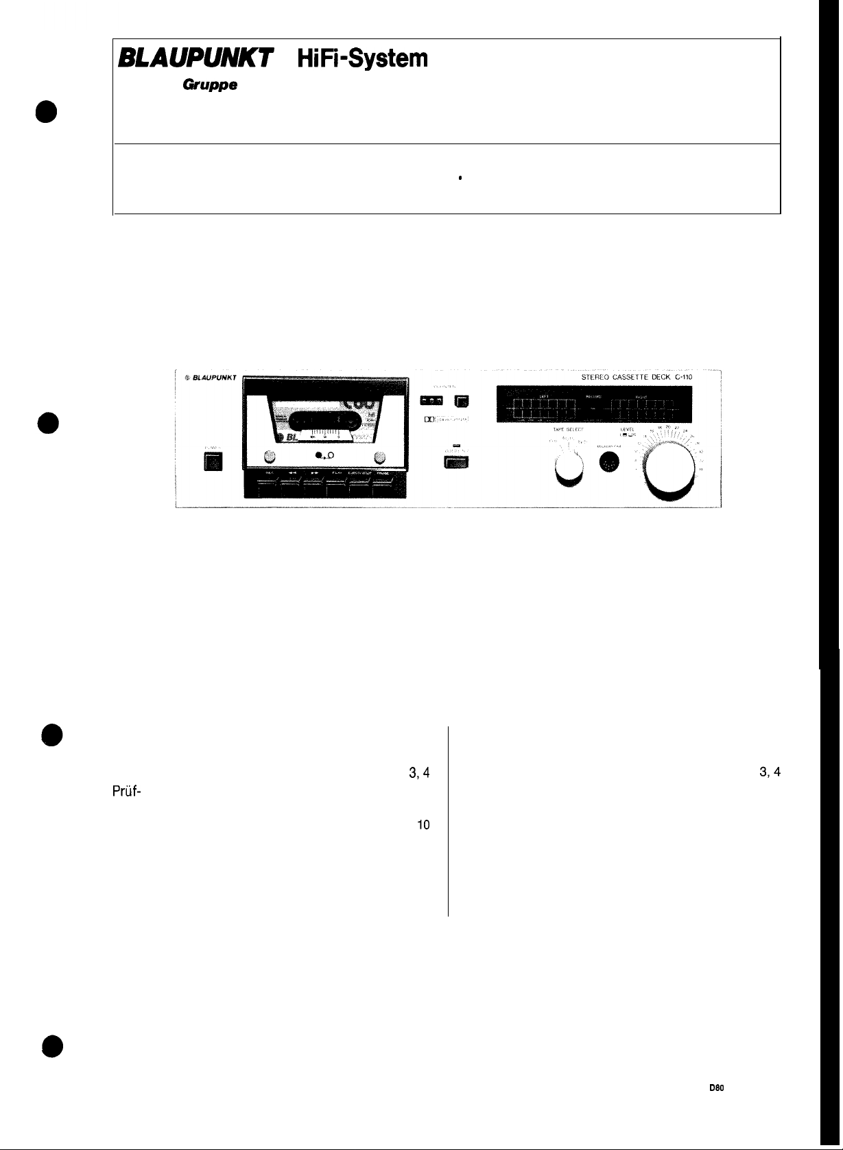
HiFi-System
STEREO CASSETTE
BOSCH @uppe
DECK C-110
7629130
Kundendienstschrift - Service Manual
lnhaltsverzeichnis
Technische Daten
Zerlegungs- und Reparaturhinweise
Pruf- und Abgleichhinweise
Bestiickungsplan
Schaltbild
Ersatzteilliste, elektr. Bauteile
Ersatzteilliste, Gerat
Explosionszeichnung, Gerat
Ersatzteilliste, Laufwerk
Explosionszeichnung, Laufwerk
Seite
2
3,4
5-7
8
9,
IO
11
12
13
14
15
Table of Contents
Technical Data
Disassembly and Repair Hints
Test and Alignment Hints
Component Plan
Circuit Diagram
Spare Parts List, El. Components
Spare Parts List, Cassette Deck
Exploded View, Cassette Deck
Spare Parts List, Drive Mechanism
Exploded View, Drive Mechanism
Page
374
5-7
9,
10
11
12
13
14
15
BP/KDB 2 D80 420 004 (042)
2
8
Page 2
Blaupunkt HiFi-Gerate tibertreffen die in der DIN 45500
geforderten Werte.
Die Gerate tragen das VDE-Zeichen und erftillen daher
die einschlagigen VDE-Bestimmungen, die
Reparatur zu
Alle Bauteile die mit einem solchen Symbol n gekenn-
zeichnet sind,
den.
beachten
mussen
sind.
durch Originalteile ersetzt wer-
bei
jeder
Blaupunkt
DIN 45500.
The sets are provided with the VDE sign, thus fulfilling
the common VDE stipulations to be observed for any
repair.
All components marked by A have to be replaced by
original parts.
HiFi
units exceed the values claimed for in
Technische Daten
Bezeichnung
Netzspannung
Laufwerk
Bandgeschwindigkeit
Drift
Tonhohenschwankung
Ubertragungsbereich
Fez03
CrOn / FeCr
Rauschminderungssystem
Ruhegerauschspannungsabstand:
Fe203
Fez03
CrO2 Dolby ein
CrO2
FeCr Dolby ein
FeCr
Ubersprechdampfung (f = 1 kHz)
Hohenaussteuerbarkeit:
Fe203
CrO2
FeCr
Eingangsempfindlichkeit:
Mikrophonbuchse
DIN-Buchse
Ausgangsspannung
Loschdampfung
Umspulzeit C 60
Abmessungen:
Breite
Hohe
Tiefe
Gewicht
Eingange
Dolby ein
Dolby
Dolby
Dolby
aus
aus
aus
nach
bei
DIN:
SRL
Wert
Value
220 V, 50 Hz
Belt Drive
4,75
cmlsec
+ 1%
f
0,2%
30Hz-15kHz
30Hz-16kHz
Dolby B
64dB
56dB
65dB
57dB
66dB
58dB
37dB
-15
dB
-13
dB
-15
dB
0,2 mV/2,2 kB
3 mVl33
> 66dB
< 115sec
MICROPHONE
kQ
775 mV
435 mm
117 mm
250 mm
7
kg
LINE IN
Technical Data
Designation
Supply voltage
Drive mechanism
Tape speed
Drift
Pitch variation
Transmission range act. to DIN:
Fe203
CrOz / FeCr
Noise Reduction System
Rest to-noise ratio:
Fe203
Fez03
CrO2
CrO2
FeCr
FeCr
Cross-talk attenuation (f = 1 kHz)
Pitch control range:
Fe203
CrO2
FeCr
Input sensitivity:
Microphone jack
DIN-socket
Output voltage at SRL
Erase attenuation
Rewinding time
Dimensions:
Width
Height
Depth
Weight
Inputs
Dolby on
Dolby off
Dolby on
Dolby off
Dolby on
Dolby off
Ausgang
Farbe:
Gehause
Frontplatte
LINE OUT
braun met.
hellbronze
-2-
output
Colour:
Chassis: brown metallic
Front panel: light bronze
Page 3
Zerlegungs- und Reparaturhinweise
Disassembly and Repair Hints
1. Abnehmen des Gehlusedeckels
a) Die zwei Schrauben an beiden
a
.
e
e
8. Ausbau der Andruckrolle
@
10. Ausbau der Wickelteller
entfernen.
b) Den Gehausedeckel
2. Abnehmen der Frontplatte
a) Die Drehknopfe des TAPE-SELECT-Schalters
und des LEVEL-Reglers abziehen.
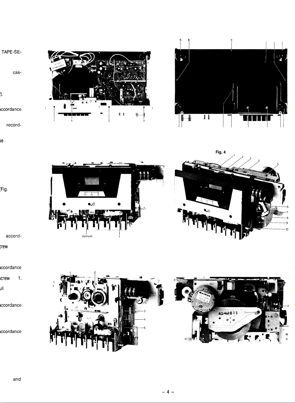
b) Die Schrauben 1-3 (Fig. 1) entfernen.
c) Die Schrauben l-5 (Fig. 2) entfernen.
d) Die beiden Randelschrauben mit der
tenblende entfernen.
e) Die Frontplatte herausziehen.
3. Abnehmen der Bodenplatte
a) Die Schrauben 1-6 sowie 9-14 (Fig. 2) ent-
fernen.
b) Die Bodenplatte abnehmen.
4. Ausbau des Laufwerks
a)
Gerat
gema8
Ziffer 2 und 3 zerlegen.
b) Die Schrauben 7 und 8 (Fig. 2) entfernen.
c)
AnschluOkabel
platine abloten, Stecker des Lbschkopfes
ziehen.
d) Zuleitungskabel am Laufwerk
e) Die Schraube 4 (Fig. 1) entfernen.
g) Die Schraube 3 (Fig. 6) entfernen.
h) Den Reedkontakt
nehmen.
i) Den Bowdenzug laufwerksseitig abnehmen.
k) Das Laufwerk
5. Ausbau von Cassettenfach und Blende
a) Sicherungsscheiben 6, 10 (Fig. 4) sowie die
Htilse
7 entfernen.
b) Die Schraube 9 (Fig. 4) entfernen und den
Hebel8 (Fig. 4)
c) Cassettenfach
d) Die Schrauben 1, 2 (Fig. 4) und 2 (Fig. 6) ent-
fernen.
e) Blende
6. Ausbau des Antriebsmotors
a) Laufwerk gema Ziffer 5 zerlegen.
b) Die Schrauben 3-5 (Fig. 4) sowie 3 (Fig. 5)
entfernen.
c) Antriebsriemen
nehmen.
7. Ausbau der Capstanwelle
a) Gerat
b) Die Schrauben 4, 5 (Fig. 5) sowie 1 (Fig. 6) ent-
fernen.
c) Lagerschild abnehmen und Capstanwelle
ausziehen.
a) Gerat
b) Sicherungsscheibe 1 (Fig. 3) entfernen und
Andruckrolle abziehen.
9. Ausbau des A/W-Kopfes
a) Gerat
b) Die zwei Halteschrauben entfernen.
c)
Nach
muthwinkel neu einzustellen (Ziffer 4, Seite 5).
a)
Gerat gem% Ziffer 4 und 5 zerlegen.
b) Halteklammern 1, 2 (Fig. 5) aufbiegen und Wik-
kelteller abziehen.
aushangen
gem%
Ziffer 5 zerlegen.
gemal3
Ziffer 2 zerlegen.
gemal3
Ziffer 2 zerlegen.
Austausch des A/W-Kopfes ist der Azi-
nach
hinten herausziehen.
des A/W-Kopfes an der
aus
der Gummihalterung
nach hinten
aushangen.
aushangen
aushangen
herausnehmen.
und entfernen.
und entfernen.
und Motor
Gerateseiten
Casset-
Haupt-
ab-
abloten.
heraus-
her-
1.
Removal of chassis cover
a) Remove the two screws on either side of the
cassette deck.
b) Remove chassis cover to the rear.
2.
Removal of front panel
a) With draw the rotary knobs of the TAPE-SE-
LECT switch and of the LEVEL control.
b) Remove screws 1-3 (Fig. 1).
c) Remove screws l-5 (Fig. 2).
d) Remove the two knurled screws with the cas-
sette mask.
e) Pull out front panel.
3.
Removal of bottom plate
a) Remove screws l-6 and 9-14 (Fig. 2).
b) Remove bottom plate.
4.
Removal of drive mechanism
a) Disassemble the cassette deck in accordance
with Items 2 and 3.
b) Remove screws 7 and 8 (Fig. 2).
c) Unsolder the connecting cable of the record-
ing/playback head at the main PC board and
pull off the erasure head connector.
d) Unsolder the feed-in cable at the drive motor.
e) Remove screw No. 4 (Fig. 1).
g) Remove screw No. 3 (Fig. 6).
h) Remove the Reed contact from the rubber
mounting.
i) Remove the
drive motor.
h) Remove the drive mechanism to the rear.
5.
Removal of the cassette bay and mask
a) Remove locking washers 6 and IO (Fig. 4) and
sleeve No. 7.
b) Remove screw No. 9 (Fig. 4) and unhinge lever
No. 8 (Fig. 4).
c)
Unhinge and remove cassette bay.
d) Remove screws 1 and 2 (Fig. 4) and No. 2
(Fig. 6).
e) Unhinge and remove mask.
6.
Removal of the drive motor
a) Disassemble the drive mechanism in accord-
ance with Item 5.
b) Remove screws 3-5 (Fig. 4) and screw No. 3,
(Fig. 5).
c)
Remove the drive belt and take the motor out.
7.
Removal of capstan shaft
a) Disassemble the cassette deck in accordance
with Item 5.
b)
Remove screws 4 and 5 (Fig.5)and screw No.
(Fig. 6).
c) Remove the bearing plate and pull out the
capstan shaft.
8.
Removal of rubber pinch roller
a) Disassemble the equipment in accordance
with Item 2.
b) Remove the locking washer No.1 (Fig. 3) and
pull off the rubber pinch roller.
9.
Removal of the recording/playback head
a) Disassemble the cassette deck in accordance
with Item 2.
b) Remove the two mounting screws.
c) Readjust the Azimuth angle (Item 4, Page 5)
after replacement of the recording/playback
head (Fig. 4, Page 5).
10.
Removal of the spindels
a) Disassemble the equipment in accordance with
Item 4 and 5.
b) Bend open holding clamps 1 and
pull off spindle.
Bowden
cable at the side of the
2(Fig.
1,
5)and
-3-
Page 4
side of the
TAPE-SE-
01.
th the
cas-
!).
accordance
the
record-
board and
/e motor.
Fig. 1
? 9
Fig. 2
,,
the rubber
side of the
rear.
:Fig. 4) and
hinge lever
and No. 2
in accord-
:rew
No. 3,
iotor out.
accordance
icrew
No.
1,
ull
out the
Fig. 3
Fig. 5 Fig. 6
accordance
Fig. 3) and
ad
accordance
4, Page 5)
g/playback
‘dance with
(Fig. 5)
an’d
-4-
Page 5
Priif-
fe
und Abgleichhinweise
Anmerkung:
Vor
allen
Messungen
Teile wie Magnetkopfe, Fiihrungen,
magnetisiert werden. Abgleichwerkzeuge
nichtmagnetisierbarem Material bestehen. Andruck-
rolle
und Kopfspiegel gegebenenfalls mit Spiritus
nigen.
Achtung! Die Filter L 201 und L 202 durfen nicht ver-
dreht werden!
Erforderliche
1.
Tongenerator 30 Hz - 20 kHz, 05 V Output
2. Voltmeter mit Effektivwertanzeige, f L 120 kHz,
RiIlMQ
3. Wow and Fluttermeter
4. Testcassetten
a) Drehmoment-Prufcassette
b) 3150 Hz- Aufzeichnung
c) 10000 Hz- Aufzeichnung
d) BASF-DIN-Bezugsband Fe,TPl8 Charge T 308s
e) BASF-DIN-Bezugsband Cr,TP18 Charge T401
f) AGFA-Referenzleerband
g) BASF-Dolby-Pegel400 Hz TM 60
5. Federwaage 600 g
(z. B. BP Best.-Nr. 8627000358)
1. Messung der
Die AnpreOkraft der Federwaage wird an der
lenachse mit einer Federwaage gemessen und
300-600 g betragen. Hierzu ist die Andruckrolle
Wiedergabe mit der Federwaage etwas abzuheben.
Bei
zu geringer AnpreOkraft die Andruckrollenein-
heit
2. Messung des Bandzuges
a)
DrehmomentmeOcassette
b)
Gerat
3. Einstellung der Bandgeschwindigkeit
a) Wow and Fluttermeter
b) Testcassette 3150 Hz abspielen.
c) Mit dem im Motor befindlichen Potentiometer
4. Einstellung des Azimuthwinkels
a) Testcassette 10000 Hz abspielen.
b) Mit der Justierschraube (Fig. 3) die
5. Einstellung des Wiedergabepegels
a) TAPE-SELECT-Schalter auf
b) DOLBY-Taste auf ,,AUS“.
c) Dolby 400 Hz-Cassette abspielen.
d) Mit den Potentiometern VR 101 (L) und VR 102
Achtung! Diese Einstellung wird fur den folgenden
Abgleich vorausgesetzt.
6. Einstellung der Aussteuerungsanzeige
a) TAPE-SELECT-Schalter auf
b) DOLBY-Taste auf ,,AUS“.
c) Dolby 400 Hz Cassette abspielen.
d) Mit den Potentiometern VR 107 (L) und VR 108
MeBmittel:
(z. B. BP Best.-Nr. 8627000356)
mit der darin enthaltenen Feder
auf Wiedergabe schalten.
Das Drehmoment
VRl (siehe Fig. 6) die Sollgeschwindigkeit von
4,75
cm/set einstellen. Die Drift darf hierbei
+ 1 %, die Tonhohenschwankung + 0,2%
tragen.
peqel
beider
(R) am NF-Ausgang des Gerates 700 mV +
0,5 dB
einstellen (siehe Fig. 9,10).
(R) die Anzeige so einstellen, da8 die 0-dB-LED
satt leuchtet, die 3-dB-LED jedoch
bleibt (siehe Fig. 9).
mussen
AnpreOkraft
sol1
Kanale
auf Maximum einstellen.
die bandberuhrenden
Capsten
4,75/3,81 FeCr
einlegen.
ca. 40-70
anschlie8en
Cr0.z
Cr02
usw. ent-
miissen aus
austauschen.
gem
betragen.
und
eichen.
Ausgangs-
stellen.
stellen.
noch
dunkel
rei-
Rol-
sol1
bei
be-
Test and Alignment Hints
Note:
Prior to any measurements all parts contacting the
tape, e.g. magnetic heads, guidings, capstan etc. have
tobe demagnetized. The alignment tools have to con-
sist of non-magnetizable material. Clean rubber pinch
roller and mirrors of head with alcohol, if necessary.
Attention! Filters L 201 and L 202 must not be tuned.
Measurement equipment required:
1. Audio-frequency oscillator 30 Hz - 20 kHz, 0.5 V
output
2. Voltmeter with r.m.s. value display, f 2 120 kHz,
RiLlMQ
3.
Wow and flutter meter
4. Test cassettes
a) Torque test cassette
(e.g. BP, Order No. 8627000356)
b) 3150 Hz- recording
c) 10000 Hz- recording
d) BASF DIN Ref. tape Fe, TP 18 Charge T 308 S
e) BASF DIN Ref. tape Cr, TP 18 Charge T 401
R
-5-
f) AGFA unrecorded referent tape
g) BASF Dolby-Level 400 Hz TM 60
5. Spring balance, 600 g
(e.g. BP, Order No. 8627000358)
1.
Measurement of contact pressure
The contact pressure of the rubber pinch roller is
measured at the roller axis by means of a string
balance. It should amount to 300-600 g. The rubber
pinch roller is to be slightly lifted by means of the
spring balance in playback for that purpose. If the
contact pressure is to low, replace rubber pinch
roller unit together with the spring contained in it.
2.
Measurement of tape tension
a) Load torque measurement cassette.
b) Set the unit to playback.
The torque should be 40-70
3.
Adjustment of tape speed
a) Connect the wow and flutter meter and cali-
brate.
b) Playback test cassette 3150 Hz.
c) Adjust the nominal speed of 4.75 cm/set by
means of the potentiometer VRl (see Fig. 6) in
the motor. In this connection a drift of + 1% and
a pitch variation of + 0,2 % is acceptable.
4. Azimuth angle adjustment
a) Play-back the 10000 Hz test cassette.
b) Adjust the output levels of both channels to
maximum by means of the adjustment screw
(see Fig. 3).
5. Adjustment of reproduction levels
a)
Set TAPE SELECT switch to CrOz.
b) Set DOLBY-key to “OFF“.
c)
Play-back the 400 Hz Dolby cassette.
d) Adjust 700 mV +- 0.5 dB at the AF unit output by
means of potentiometers VR 101 (L) and VR 102
(R) (see Fig. 9 and 10).
Attention: This adjustment is a requirement for the
following alignment.
6.
Adjustment of the recording level display
a) Set TAPE SELECT switch to
b) Set DOLBY-key to “OFF“.
c) Play-back 400 Hz Dolby cassette.
d) Adjust display by means of potentiometers
VR 107 (L) and VR 108 (R) such that the
LED is fully illuminated, and that the 3-dB-LED
is still dark (see Fig. 9).
gem,
CrOn.
R
4.7513.81 FeCr
approximate.
O-dB-
Priif- u’
7.
Einstc
a)
Prl
b)
D(
c)
DII
LE
d)
Gc
LE
m’
e)
NF
let
ne
ml
nE
bit
!ilE
8.
Einstc
a) Pr
b)
DI’
SE
c)
Gc
d) Mi
Mi
70
9.
Freqr
a) Pr
b) DI
SF
c)
D(
d)
Gc
Lf
3:
4
M
le
dc
f)
:;
Fc
g)
il
bc
10. DOL
4
b) N
cl D
d)
4
f) bJ
9) c
h) h
P
IE
S
G
D
(1
;
Page 6

Priif-
und Abgleichhinweise Test and Alignment Hints
7. Einstellung des Aufnahmepegels
a) Prufaufbau gema Fig. 10 erstellen.
b) DOLBY-Taste auf ,,AUS“.
c) DIN-Bezugsband Fe einlegen und TAPE-SE-
LECT-Schalter auf
d) Gerat auf Aufnahme schalten und mit dem
LEVEL-Regler an
mV einstellen (siehe Fig. 9).
e) NF-Generator auf 333 Hz
len und mit dieser Einstellung mehrmals auf-
nehmen und wieder abspielen. Die Potentiometer VR 105 (L) und VR 106 (R) vor jeder Auf-
nahme in
bis am
gabe 775 mV anliegen.
MPG(L)
Fez03
stellen.
MPO
(L) und
(0,5
V Output) einstel-
kleinen
Schritten soweit verstellen,
und
MPe(R) such bei
MPO
(R) 775
Wieder-
7.
Adjustment of the recording level
a)
Provide test setup in accordance with Fig. 10.
b) Set DOLBY-key to “OFF“.
c) Load DIN reference tape Fe, and set the TAPE-
SELECT switch to
d) Set unit to recording and adjust 775 mV by
means of the LEVEL control at MP 0 (L) and
MPe(R)
e) Set AF generator to 333 Hz (0.5 V output) and
record and play-back several times using this
adjustment. Change the setting of potentiometers VR 105 (L) and VR 106 (R) before each
recording in small increments such that 775
are present at
case of playback.
(see Fig. 9).
MPO(L)
FezO3.
mV
and MP@(R) also in the
8. Einstellung der HF-Vormagnetisierung
a) Prtifaufbau gema Fig. 8 erstellen.
b) DIN-Bezugsband Cr einlegen und TAPE-
SELECT-Schalter auf
c) Gerat auf Aufnahme schalten.
d) Mit VR 301 (L) bzw. VR 302 (R) an den in die
Masseleitungen geschalteten Widerstanden
70 mV einstellen.
9. Frequenzgangkontrolle
a) Prufaufbau
b) DIN-Bezugsband Fe einlegen und TAPE;
SELECT-Schalter auf
c) DOLBY-Taste auf ,,AUS”.
d) Gerat auf Aufnahme schalten und mit dem
LEVEL-Regler an MP 0 (L) und MP 0 (R)
39 mV (-26
e) Mit 1
len. Der NF-Ausgangspegel mu8
des in Fig. 7 dargestellten Toleranzfeldes
wegen.
f)
Entsprechend den Frequenzgang mit
FeCr
feld mu8
werden.
g) Der Frequenzgang kann mit VR
benenfalls korrigiert werden (siehe Ziffer 8).
gemal3
dB)
kHz
und 10
Bezugsband kontrollieren. Das Toleranz-
such bei
CrOn
stellen.
Fig. 10 erstellen.
Fe203
stellen.
einstellen.
kHz
aufnehmen und
sich
Dolby-Betrieb eingehalten
301/302 gege-
innerhalb
abspie-
CrO2
be-
und
8.
Adjustment of RF bias magnetization
a)
Provide test setup in accordance with Fig. 8.
b) Load DIN reference tape Cr and set TAPE
SELECT switch to
c) Set unit to recording.
d) Adjust 70 mV on the resistors inserted in the
ground lines by means of VR 301 (L) and VR 302
CrOn.
(W
9. Test frequency response
a) Provide test setup in accordance with
b) Local the DIN reference tape Fe and set the
TAPE-SELECT switch to
c) Set the DOLBY key to “OFF”.
d) Set unit to recording and set 39 mV (-26
by means of the level control and
MP O(R).
e) Record at 1
AF output level must be within the tolerance
limits shoun in Fig. 7.
f)
Check the frequency response by means of the
CrOn
and
limits also have to be observed in the case of
DOLBY operation.
g) The frequency response may be corrected, if
required, by means of VR
kHz
and 10
FeCr
reference tape. The tolerance
Fe203.
MPO(L)
kHz
and play-back.The
301/302
(see Item 8).
.
0
Fig.10.
dB)
and
Fig.7
c?:d
250Hz
30Hz
10. DOLBY-Abgleich
a) Prufaufbau gema Fig. 10 erstellen.
b) NF-Generator auf 5
len.
c) DIN-Bezugscassette
SELECT-Schalter auf Fen 03 stellen.
d) Gerat auf Aufnahme schalten.
e) DOLBY-Taste auf ,,AUS“.
f) Mit dem LEVEL-Regler an
(R)
23,5 mV
g) DOLBY-Taste auf
h) NF-Voltmeter an
schliel3en
54 mV einstellen (siehe Fig. 9).
(siehe Fig. 9).
und mit VR 201 (L) bzw. VR 202 (R)
kHz (0,5
,,EIN”.
MPO
Fe203
(L) bzw.
Fe203
IOkHz
V Output) einstel-
einlegen und TAPE-
MPO
(L) und
MPe(R) an-
12.5kHz
MPO
30Hz
10. DOLBY alignment
a) Provide test setup in accordance with
b)
Set AF-generator to 5
c) Load DIN reference cassette
TAPE SELECT switch to
d) Set the cassette deck to “recording“.
e) Set the DOLBY key to “OFF“.
f) Set 23.5 mV by means of the LEVEL Control
and MPO(L) and on
g) Set the DOLBY key to “ON“.
h) Connect AF-voltmeter to
(R) and set to 54 mV by means of VR 201 (L)
and VR 202 (R) (see Fig. 9).
-6-
250Hz
Cr02/FeCr
1OkHz 15kHz
kHz
(0.5 V output).
Fe203.
MPe(R)
MPG
Fig.10.
Fe203
and set
(see Fig. 9).
(L) and
0
MPO
Page 7

Fig.
Fig. 9
8
blau
blue
Fig. 10
L
G
22
/70k
Cassettendeck
i
I
1
-7-
1
Page 8

Bestiickungsplan
BB
VR103
VRlDC
MICROPHONE
(
Component Plan
RECORD/PLAYBACK
55
’
MUNG
SW,
Dolby
PLAY.FF AUIO-511
RWD
Loschkopf
Erasehead
-8-
Page 9

Schaltbild
‘32
.7k
I
I
Hauptplatte
Ma,” board
Page 10

Circuit Diagram
Anzeigeplatte
D~sploy
I
R
I
T
I I
board
0
t--
I
0505
s-4
RfC
d
IR
2 I*
I,
c
Lc5o3
T’Q’
R50
‘70
R5I
560
sa
R5Q
It
R5Q’
It
4
Block
Blockschaltblld
Clrcult Dugram
Page 11

Ersatzteilliste
Lfd.
Nr.
Item
No.
Bezeichnung
Designation
Pos. im
Schaltbild
Pos. in
schematic
Spare
Symbol Bestell-Nr.
Part. No.
Parts List
Preis-
wrw
Price
group
Ersatzt
201
202
210
211
212
213
214
215216
221
222
223
224
225
226
227
228
229
HA11226
TA 489 CP IC
2 SA 673 (C) TR 404
2SA999(E)
2 SC 2320 (E)
2 SC 2320 L(F)
2SC1162(C)
2 SD 476 (C)
2 SD 468 (C)
lN34A
1 S 2076
HZ 18 B2 D 408 8 905 405 241 OD
RV 06 D
W06A D401-405
LED EinzeUSingle (rot/red)
LED Einzel/Single
LED 2fach/2-fold (rot/red)
LED 4fach/4-fold
(grtin/green)
(grtin/green)
IC 201
501,502
TR 403,407
TR 105,106,107,
TR 108,201,202,
TR 406
TR 1, 2, 101, 8 905 705 510 OD
TR 102,103,104
TR 301 8 905 706 643 AC
TR 401,402 8905706637
TR 302,306
D
101,102,201,
D 202
D
103,104,105,
D
106,203,204
406,407,409,
D410
D 505 8 905 405 365 OH
D 506 8 905 405 363
D
502,504
D
501,503
a
9
4L
8 905 956 056 KN
8905901899 CB
8 905 706 653
8 905 705 514 OE
8 905 705 511 OC
8 905 706 647
8 905 406 012 OC
8 905 406 018
8 905 406 002 OB
8 905 406 101
8 905 405 369 AG
8 905 405 367
E
06
A0
DF
231
232
233
234
235
236
241
242
251
261
262
Handelsiibliche Kondesatoren und Widerstande sind in der
Ersatzteilliste aufgeftihrt. Wir bitten Sie, diese Teile im Fach- the spare parts list. Kindly buy these parts from the specialized
handel zu beziehen.
5 kOhm
10
kOhm
50
kOhm VR 103,104
100
kOhm
2,2
Ohm /
0,25
39Ohm/2W
F2 L201,202 8629137020
F 1
22nF/450V-
0,5A F2
1 A
W
VR 105,106
VR 101,102,201,
VR 202
VR 107,108,301,
VR 302
R 402
R 404
T301
Cl
Fl
4-
E
-ii-
Capacitors and resistors usual in trade are not mentioned in
trade.
8 901 499 022 OF
8 901 499 025 OF
8 901 499 034 FB
8 901 499 040 OF
8900669062
8900669069
8629137019
8 903 125 332 BD
8629187000
8629187001
-
11
-
Page 12

Ersatzteilliste
Lfd.
Nr.
Item
No.
16
17
18
20
21
22
26
28
30
34
37
35
38
39
40
42
43
44
45
46
47
49
50
51
z
54
55
56
57
58
59
61
E
66
67
68
72
73
74
75
Bezeichnung
1
Frontrahmen
2
Netzschalter
4
Anzeigehalter
6
Platine
Spreizstift
cl
Gummilager
Laufwerk
10
Schalter
11
12
Winkel
13
Halterung
Tragerblech
Blende
Farbfilter
Cassettenfach
Rahmen
Feder
Feder
Halterung
Dampfer
Taste
Winkel
RECORD-Taste
Winkel
Tragerblech
Netztransformator
Lotstutzpunkt
Gehauseseite
Diodenstecker
Zugentlastung
Netzkabel
Zugentlastung
Bowdenzug
Tastknopf
Tastknopf
Frontplatte
Drehknopf
Drehknopf
Schaltknopf
Blende
Schraube
Bodenblech
SchraubfuB
Gehausedeckel
Reedkontakt
Platine
Platine
Platine
Scheibe
Potentiometer
TAPE-SELECT-Schalter
DOLBY-Taste
Schiebeschalter
Designation
Frontframe
Power switch
Display
holder
PC
board
Spreading pin
Rubber support
Drive mechanism
Switch
Angle
Holder
Carrier
plate
Mask
Colour
Filter
Cassette
Frame
bay
Spring
Spring
Holder
Damper
Key
Angle key
RECORD
Angle
Carrier
plate
Mains
transformer
Soldering
Chassis
Diode
terminal
side part
connector
Traction relief
Power cable
Traction
relief
Bowden cable
Key button
Key button
Front panel
Rotary knob
Rotary knob
Switch knob
Mask
Screw
Botton plate
Screwed-on-foot
Chassis
cover
Reed contact
PC board
PC
board
PC board
Washer
Potentiometer
TAPE-SELECT switch
DOLBY key
Slide switch
Snnm Park
-r-.
-
. U. .Y
Preis-
Bestell-Nr.
Part No.
g;ipcpe”
group
8 629 107 010
8629127200 CK
8629107011
8 629 137 409
8 629 117 517
8629117105
8629127405 UY
8629127611
8629117111
8629117112
8629117113
8629117114
8629117120
8629107018 CH
8629107017
8629117601
8629117600
OG
OH
8629117115
8629117116
8629117016
8629117017
E
8629107025
8629107026
8629117121
8 629 137 202
LN
8629127615
8 629 107
029
8 629 197 701 FB
8629117900
8 629 197 703
8629117901
8 629 127 232
8629117000
8629117001
AB
OD
8629107006
8629117010
8629117011
DMAR
CE
8629117012 CB
8629107014
8629117500
i::
8629107030
8629107035
8629107031
8 629 127 222 AE
8629127900
8629127903
8629127902
8 629 127 901
8901499034
8 629 127 221
8629127209
8 629 127 220
FB
EG
&
I
id
II.“.
-
12
-
Page 13

Explosionszeichnung Exploded View
Hinweis: Die Zahlen in der Explosionszeichnung entsprechen
der Lfd. Nr. in der Ersatzteilliste.
Note: The numbers in the exploded view correspond with the
Item No. given in thespare parts list.
-
13
-
Page 14

Ersatzteilliste
Lfd.
Nr.
Item
No.
Bezeichnung
Designation
Spare Parts List
Bestell-Nr.
Part No.
Preis-
wrwe
Price-
group
101
104 Winkel
106 Hebel
110
111
116
117 Losch kopf
121
124 Wickelteller
125
128 Wickelteller
130
133 Schieber
135 Lagerblech
136 Lager
139 Schwungmasse
141
143 Hebel
144 Schieber
146 Winkel
148
149 Antriebsachse
150
151
155 Schieber
159
161
164 Hebel
167 Hebel
171
174 Zahlwerk
175
176 Riemen
178 Schalter
179 Winkel
180 Feder
185
186 Hebel
187 Schalter
Chassis
Kopftrager
Kopftrager
A/W-Kopf
Andruckrolle
Antriebsrolle
Antriebsrolle
Schieber
Antriebsmotor
Antriebsriemen
Motorhalterung
Tastenaggregat
Schieber
Bremse
Zahlwerkhalterung
Elektromagnet
Chassis
Angle
Lever
Head carrier
Head carrier
Recording/Playback
Erasure head
Rubber pinch roller
Spindle
Drive roller
Spindle
Drive roller
Slide
Support plate
Support
Gyrating mass
Slide
Lever
Slide
Angle
Drive motor
Drive axle
Drive belt
Motor mount
Slide
Key mechanism
Slide
Lever
Lever
Brake
Counter
Counter support
Belt
Switch
Angle
Spring
Electromagnet
Lever
Switch
8629107027
8629117125
8629117126
8629117127
8629117128
8629137600
8629137601
8629117212
8629117213
8629117214
8629117215
8629117216
8629117217
8629117129
8629117130
8629117218
8629117131
8629117132
8629117133
8 629 127 216
8629127402
8629117219
8629117905
8629117134
8 629 117 135
8 629 i 27 235
8629117136
8629117137
8629117138
8629117139
8629127410
8 629 117 140
8 629 117 906
8629117141
8629117142
8629117610
8629137024
8629117143
8629127226
KN
CE
a
Schrauben
Scheiben
Federn
Screws
Washers
Springs
8627000570
8627000571
8627000572
a
-
14
-
Page 15

Explosionszeichnung
I
Exploded View
116
178
,324
I
Hinweis: Die Zahlen in der Explosionszeichnung entsprechen
der Lfd. Nr. in der Ersatzteilliste.
Note: The numbers in the exploded view correspond with the
Item No. given in the spare parts list.
-
15
-
 Loading...