

BK Precision 9103, 9104 User Manual

Model 9103 and 9104
Multi-Range DC Power Supply
USER MANUAL
www. .com
information@itm.com1.800.561.8187

Safety Summary
The following safety precautions apply to both operating and maintenance personnel and must
be followed during all phases of operation, service, and repair of this instrument.
Before applying power to this instrument:
Read and understand the safety and operational information in this manual.
Apply all the listed safety precautions.
Verify that the voltage selector at the line power cord input is set to the correct line voltage.
Operating the instrument at an incorrect line voltage will void the warranty.
Make all connections to the instrument before applying power.
Do not operate the instrument in ways not specified by this manual or by B&K Precision.
Failure to comply with these precautions or with warnings elsewhere in this manual violates the
safety standards of design, manufacture, and intended use of the instrument. B&K Precision
assumes no liability for a customer’s failure to comply with these requirements.
Category rating
The IEC 61010 standard defines safety category ratings that specify the amount of electrical
energy available and the voltage impulses that may occur on electrical conductors associated
with these category ratings. The category rating is a Roman numeral of I, II, III, or IV. This rating
is also accompanied by a maximum voltage of the circuit to be tested, which defines the voltage
impulses expected and required insulation clearances. These categories are:
Category I (CAT I): Measurement instruments whose measurement inputs are not intended to
be connected to the mains supply. The voltages in the environment are typically derived from a
limited-energy transformer or a battery.
www. .com
information@itm.com1.800.561.8187

Category II (CAT II): Measurement instruments whose measurement inputs are meant to be
connected to the mains supply at a standard wall outlet or similar sources. Example
measurement environments are portable tools and household appliances.
Category III (CAT III): Measurement instruments whose measurement inputs are meant to be
connected to the mains installation of a building. Examples are measurements inside a
building's circuit breaker panel or the wiring of permanently-installed motors.
Category IV (CAT IV): Measurement instruments whose measurement inputs are meant to be
connected to the primary power entering a building or other outdoor wiring.
Do not use this instrument in an electrical environment with a higher category rating than what
is specified in this manual for this instrument.
You must ensure that each accessory you use with this instrument has a category rating equal
to or higher than the instrument's category rating to maintain the instrument's category rating.
Failure to do so will lower the category rating of the measuring system.
Electrical Power
This instrument is intended to be powered from a CATEGORY II mains power environment. The
mains power should be 120 V RMS or 240 V RMS. Use only the power cord supplied with the
instrument and ensure it is appropriate for your country of use.
Ground the Instrument
To minimize shock hazard, the instrument chassis and cabinet must be connected to an
electrical safety ground. This instrument is grounded through the ground conductor of the
supplied, three-conductor AC line power cable. The power cable must be plugged into an
approved three-conductor electrical outlet. The power jack and mating plug of the power cable
meet IEC safety standards.
www. .com
information@itm.com1.800.561.8187

Do not alter or defeat the ground connection. Without the safety ground connection, all
accessible conductive parts (including control knobs) may provide an electric shock. Failure to
use a properly-grounded approved outlet and the recommended three-conductor AC line
power cable may result in injury or death.
Unless otherwise stated, a ground connection on the instrument's front or rear panel is for a
reference of potential only and is not to be used as a safety ground.
Do not operate in an explosive or flammable atmosphere
Do not operate the instrument in the presence of flammable gases or vapors, fumes, or finelydivided particulates.
The instrument is designed to be used in office-type indoor environments. Do not operate the
instrument
In the presence of noxious, corrosive, or flammable fumes, gases, vapors, chemicals, or finelydivided particulates.
In relative humidity conditions outside the instrument's specifications.
In environments where there is a danger of any liquid being spilled on the instrument or where
any liquid can condense on the instrument.
In air temperatures exceeding the specified operating temperatures.
In atmospheric pressures outside the specified altitude limits or where the surrounding gas is
not air.
In environments with restricted cooling air flow, even if the air temperatures are within
specifications.
In direct sunlight.
This instrument is intended to be used in an indoor pollution degree 2 environment. The
operating temperature range is 0 °C to 40 °C and the operating humidity range is up to 80%
relative humidity with no condensation allowed.
www. .com
information@itm.com1.800.561.8187

Measurements made by this instrument may be outside specifications if the instrument is used
in non-office-type environments. Such environments may include rapid temperature or
humidity changes, sunlight, vibration and/or mechanical shocks, acoustic noise, electrical noise,
strong electric fields, or strong magnetic fields.
Do not operate instrument if damaged
If the instrument is damaged, appears to be damaged, or if any liquid, chemical, or other
material gets on or inside the instrument, remove the instrument's power cord, remove the
instrument from service, label it as not to be operated, and return the instrument to B&K
Precision for repair. Notify B&K Precision of the nature of any contamination of the instrument.
Clean the instrument only as instructed
Do not clean the instrument, its switches, or its terminals with contact cleaners, abrasives,
lubricants, solvents, acids/bases, or other such chemicals. Clean the instrument only with a
clean dry lint-free cloth or as instructed in this manual.
Not for critical applications
This instrument is not authorized for use in contact with the human body or for use as a
component in a life-support device or system.
Do not touch live circuits
Instrument covers must not be removed by operating personnel. Component replacement and
internal adjustments must be made by qualified service-trained maintenance personnel who
are aware of the hazards involved when the instrument's covers and shields are removed.
Under certain conditions, even with the power cord removed, dangerous voltages may exist
www. .com
information@itm.com1.800.561.8187
when the covers are removed. To avoid injuries, always disconnect the power cord from the
instrument, disconnect all other connections (for example, test leads, computer interface
cables, etc.), discharge all circuits, and verify there are no hazardous voltages present on any
conductors by measurements with a properly-operating voltage-sensing device before touching
any internal parts. Verify the voltage-sensing device is working properly before and after
making the measurements by testing with known-operating voltage sources and test for both
DC and AC voltages. Do not attempt any service or adjustment unless another person capable
of rendering first aid and resuscitation is present.
Do not insert any object into an instrument's ventilation openings or other openings.
Hazardous voltages may be present in unexpected locations in circuitry being tested when a
fault condition in the circuit exists.
Fuse replacement
Fuse replacement must be done by qualified service-trained maintenance personnel who are
aware of the instrument's fuse requirements and safe replacement procedures. Disconnect the
instrument from the power line before replacing fuses. Replace fuses only with new fuses of
the fuse types, voltage ratings, and current ratings specified in this manual or on the back of the
instrument. Failure to do so may damage the instrument, lead to a safety hazard, or cause a
fire. Failure to use the specified fuses will void the warranty.
Servicing
Do not substitute parts that are not approved by B&K Precision or modify this instrument.
Return the instrument to B&K Precision for service and repair to ensure that safety and
performance features are maintained.
www. .com
information@itm.com1.800.561.8187

Cooling fans
This instrument contains one or more cooling fans. For continued safe operation of the
instrument, the air inlet and exhaust openings for these fans must not be blocked nor must
accumulated dust or other debris be allowed to reduce air flow. Maintain at least 25 mm
clearance around the sides of the instrument that contain air inlet and exhaust ports. If
mounted in a rack, position power devices in the rack above the instrument to minimize
instrument heating while rack mounted. Do not continue to operate the instrument if you
cannot verify the fan is operating (note some fans may have intermittent duty cycles). Do not
insert any object into the fan's inlet or outlet.
Use correctly sized wires
To connect a load to the power supply, use a wire diameter large enough to handle the
maximum continuous output short-circuit current of the power supply without the wire
overheating.
For continued safe use of the instrument
Do not place heavy objects on the instrument.
Do not obstruct cooling air flow to the instrument.
Do not place a hot soldering iron on the instrument.
Do not pull the instrument with the power cord, connected probe, or connected test lead.
Do not move the instrument when a probe is connected to a circuit being tested.
Certification
We certify that this product met its published specifications at time of shipment from the
factory.
www. .com
information@itm.com1.800.561.8187

Compliance Statements
Disposal of Old Electrical & Electronic Equipment (Applicable in the European Union and other
European countries with separate collection systems).
This product is subject to Directive 2002/96/EC of the European
Parliament and the Council of the European Union on waste electrical and
electronic equipment (WEEE), and in jurisdictions adopting that Directive,
is marked as being put on the market after August 13, 2005, and should
not be disposed of as unsorted municipal waste. Please utilize your local
WEEE collection facilities in the disposition of this product and otherwise
observe all applicable requirements.
www. .com
information@itm.com1.800.561.8187

CE Declaration of Conformity
The power supply meets the requirements of 2006/95/EC Low Voltage Directive and
2004/108/EC Electromagnetic Compatibility Directive.
Low Voltage Directive
EN 60950-1
EN 61010-1
EMC Directive
EN 55011
EN 55022
EN 55024
EN61000-3-2
EN61000-3-3
EN61000-6-1
www. .com
information@itm.com1.800.561.8187
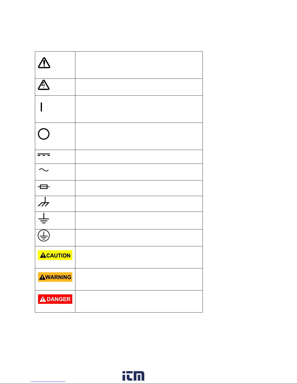
Safety Symbols
Refer to the user manual for warning information
to avoid hazard or personal injury and prevent
damage to instrument.
Electric Shock hazard
On (Supply). This is the AC mains
connect/disconnect switch on the front of the
instrument.
Off (Supply). This is the AC mains
connect/disconnect switch on the front of the
instrument.
Direct current
Alternating current
Fuse Symbol
Chassis (earth ground) symbol
Ground terminal
Protective earth ground
CAUTION indicates a hazardous situation which, if
not avoided, will result in minor or moderate injury
WARNING indicates a hazardous situation which, if
not avoided, could result in death or serious injury
DANGER indicates a hazardous situation which, if
not avoided, will result in death or serious injury.
www. .com
information@itm.com1.800.561.8187

Contents
Safety Summary .................................................................................................................... 2
Compliance Statements ......................................................................................................... 8
CE Declaration of Conformity ................................................................................................. 9
Safety Symbols .................................................................................................................... 10
1 General Information ........................................................................................................ 13
1.1 Product Overview ............................................................................................................... 13
1.2 Package Contents ............................................................................................................... 13
1.3 Input Power ........................................................................................................................ 14
1.4 Fuse Requirements ............................................................................................................. 14
1.5 Fuse Replacement .............................................................................................................. 14
2 Controls and Indicators ................................................................................................... 15
2.1 Front Panel ......................................................................................................................... 15
2.2 Rear Panel ........................................................................................................................... 16
3 Operating Instructions ..................................................................................................... 17
3.1 Safety Precautions .............................................................................................................. 17
3.2 Using Keypad and Control Knobs ....................................................................................... 18
Keypad ............................................................................................................................. 18
Control Knobs .................................................................................................................. 18
3.3 Menu/Shift button and Key Lock button functions ........................................................... 18
Upper Voltage Limit (UVL) ............................................................................................... 18
Upper Current Limit......................................................................................................... 18
To activate the Remote Control Mode............................................................................ 18
Deactivating Remote Control Mode ............................................................................... 19
Factory Reset ................................................................................................................... 19
Changing Ammeter to Wattmeter. ................................................................................. 20
The Key Lock button ........................................................................................................ 20
4 Operating Modes ............................................................................................................ 21
4.1 Normal Mode ..................................................................................................................... 21
Powering on the power supply ....................................................................................... 21
Connect the device under test to the power supply....................................................... 21
Turn on the Power Supply ............................................................................................... 22
www. .com
information@itm.com1.800.561.8187

Changing Ammeter to Wattmeter .................................................................................. 22
Key Lock Function ............................................................................................................ 22
Changing the values of UVL and UCL .............................................................................. 23
4.2 Preset Mode ....................................................................................................................... 23
4.3 Transient Mode .................................................................................................................. 24
Step Size (seconds) .......................................................................................................... 25
Transition time: ............................................................................................................... 25
Select First Step ............................................................................................................... 26
Number of Cycles ............................................................................................................ 26
Transient Mode: Examples .............................................................................................. 26
4.4 Analog Remote Control ...................................................................................................... 31
How to Enter Remote Control Mode .............................................................................. 31
To deactivate the Remote Control Mode ....................................................................... 31
Analog Remote Control Methods and Set Ups ............................................................... 32
Analog Remote Control: Voltage Control ........................................................................ 33
Remote Enable and Disable the Output .......................................................................... 36
4.5 PC Interface Control ........................................................................................................... 36
5 Remote Sensing .............................................................................................................. 37
6 Protection Faults ............................................................................................................. 38
6.1 OVP: Over Voltage Protection ............................................................................................ 38
6.2 OTP: Over Temperature Protection ................................................................................... 38
6.3 OCP: Over Current Protection ............................................................................................ 39
7 Specifications .................................................................................................................. 40
Service Information ............................................................................................................. 42
Limited Two-Year Warranty ................................................................................................. 43
www. .com
information@itm.com1.800.561.8187

1 General Information
1.1 Product Overview
B&K Precision models 9103 and 9104 are multi-range power supplies differing from
conventional power supplies because voltage and current limits are varied to allow maximum
rated power to be delivered at any operating point. Contrast this to a conventional power
supply which has a maximum voltage and maximum current rating -- all operating points must
fall inside these limits.
This family of switching mode power supplies comes with a small form factor, auto cross-over
for constant voltage (CV) and constant current (CC), 3 voltage/current presets for frequentlyused settings, and remote control offering versatility for various applications.
The dual action (coarse/fine) tuning makes setting the voltage and current levels smooth,
precise, and fast. Setting, changing, and checking the current limit level can be done without
shorting the output.
Operating software through the USB interface allows turning the output power on or off and
the voltage and current can be adjusted without using the front panel. Up to 20 timed steps of
voltage and current, each with its own time duration from 1 s to 600 s, can be programmed for
up to 999 cycles.
A DC ramp or pulsed waveforms can be generated by the front panel or by the supplied
software with a preview of the final waveform. The 3 user defined presets facilitate quick
access to frequently used VI settings.
1.2 Package Contents
Please inspect the instrument mechanically and electrically upon receiving it. Unpack all items
from the shipping carton, and check for any obvious signs of physical damage that may have
occurred during transportation. Report any damage to the shipping agent immediately. Save
the original packing carton for possible future reshipment. Every instrument is shipped with the
following contents:
• 1x 9103/9104 DC Power Supply
• 1x USB Cable
• 1x Analog Control Connector
• 1x AC Power Cord
www. .com
information@itm.com1.800.561.8187
 Loading...