

BK Precision 880 Instruction Manual

Model 880
Dual Display LCR METER
INSTRUCTION MANUAL


Safety Summary
Before applying power to this instrument:
Read and understand the safety and operational information in this manual.
Apply all the listed safety precautions.
Verify that the voltage selector at the line power cord input is set to the correct line
voltage. Operating the instrument at an incorrect line voltage will void the warranty.
Make all connections to the instrument before applying power.
Do not operate the instrument in ways not specified by this manual or by B&K Precision.
Failure to comply with these precautions or with warnings elsewhere in this manual violates the
safety standards of design, manufacture, and intended use of the instrument. B&K Precision
assumes no liability for a customer’s failure to comply with these requirements.
Category rating
The IEC 61010 standard defines safety category ratings that specify the amount of electrical
energy available and the voltage impulses that may occur on electrical conductors associated
with these category ratings. The category rating is a Roman numeral of I, II, III, or IV. This rating
is also accompanied by a maximum voltage of the circuit to be tested, which defines the voltage
impulses expected and required insulation clearances. These categories are:
Category I (CAT I): Measurement instruments whose measurement inputs are not intended to
be connected to the mains supply. The voltages in the environment are typically derived from a
limited-energy transformer or a battery.
Category II (CAT II): Measurement instruments whose measurement inputs are meant to be
connected to the mains supply at a standard wall outlet or similar sources. Example
measurement environments are portable tools and household appliances.
Category III (CAT III): Measurement instruments whose measurement inputs are meant to be
connected to the mains installation of a building. Examples are measurements inside a
building's circuit breaker panel or the wiring of permanently-installed motors.
Category IV (CAT IV): Measurement instruments whose measurement inputs are meant to be
connected to the primary power entering a building or other outdoor wiring.
Do not use this instrument in an electrical environment with a higher category rating than what
is specified in this manual for this instrument.
1

You must ensure that each accessory you use with this instrument has a category rating equal
to or higher than the instrument's category rating to maintain the instrument's category rating.
Failure to do so will lower the category rating of the measuring system.
Electrical Power
This instrument is intended to be powered from a CATEGORY II mains power environment. The
mains power should be 115 V RMS or 230 V RMS. Use only the power cord supplied with the
instrument and ensure it is appropriate for your country of use.
If the instrument will not be used for a long period of time, remove the batteries.
When changing the instrument's batteries, disconnect all leads and wires connected to the
instrument before replacing the batteries. Replace with the battery types specified in this
manual.
Battery replacement
Remove all test leads from the instrument before replacing the batteries.
Do not operate in an explosive or flammable atmosphere
Do not operate the instrument in the presence of flammable gases or fumes. Operation of any
electrical instrument in such an environment constitutes a definite safety hazard.
The instrument is designed to be used in office-type indoor environments. Do not operate the
instrument
2

In the presence of noxious, corrosive, or flammable fumes, gases, vapors, chemicals, or
finely-divided particulates.
In relative humidity conditions outside the instrument's specifications.
In environments where there is a danger of any liquid being spilled on the instrument or
where any liquid can condense on the instrument.
In air temperatures exceeding the specified operating temperatures.
In atmospheric pressures outside the specified altitude limits or where the surrounding
gas is not air.
In environments with restricted cooling air flow, even if the air temperatures are within
specifications.
In direct sunlight.
Do not operate the instrument in the presence of flammable gases or vapors, fumes, or finelydivided particulates.
This instrument is intended to be used in an indoor pollution degree 2 environment. The
operating temperature range is 0 °C to 40 °C and 20% to 80% relative humidity, with no
condensation allowed.
Measurements made by this instrument may be outside specifications if the instrument is
used in non-office-type environments. Such environments may include rapid temperature
or humidity changes, sunlight, vibration and/or mechanical shocks, acoustic noise, electrical
noise, strong electric fields, or strong magnetic fields.
Do not operate instrument if damaged
If the instrument is damaged, appears to be damaged, or if any liquid, chemical, or other
material gets on or inside the instrument, remove the instrument's power cord, remove the
instrument from service, label it as not to be operated, and return the instrument to B&K
Precision for repair. Notify B&K Precision of the nature of any contamination of the instrument.
Clean the instrument only as instructed
3

Do not clean the instrument, its switches, or its terminals with contact cleaners, abrasives,
lubricants, solvents, acids/bases, or other such chemicals. Clean the instrument only with a
clean dry lint-free cloth or as instructed in this manual.
Not for critical applications
This instrument is not authorized for use in contact with the human body or for use as a
component in a life-support device or system.
Do not touch live circuits
Instrument covers must not be removed by operating personnel. Component replacement and
internal adjustments must be made by qualified service-trained maintenance personnel who
are aware of the hazards involved when the instrument's covers and shields are removed.
Under certain conditions, even with the power cord removed, dangerous voltages may exist
when the covers are removed. To avoid injuries, always disconnect the power cord from the
instrument, disconnect all other connections (for example, test leads, computer interface
cables, etc.), discharge all circuits, and verify there are no hazardous voltages present on any
conductors by measurements with a properly-operating voltage-sensing device before touching
any internal parts. Verify the voltage-sensing device is working properly before and after
making the measurements by testing with known-operating voltage sources and test for both
DC and AC voltages. Do not attempt any service or adjustment unless another person capable
of rendering first aid and resuscitation is present.
Do not insert any object into an instrument's ventilation openings or other openings.
Hazardous voltages may be present in unexpected locations in circuitry being tested when a
fault condition in the circuit exists.
Fuse replacement
Fuse replacement must be done by qualified service-trained maintenance personnel who are
aware of the instrument's fuse requirements and safe replacement procedures. Disconnect the
instrument from the power line before replacing fuses. Replace fuses only with new fuses of
4

the fuse types, voltage ratings, and current ratings specified in this manual or on the back of the
instrument. Failure to do so may damage the instrument, lead to a safety hazard, or cause a
fire. Failure to use the specified fuses will void the warranty.
The replacement of current-measurement mode protection fuses in multimeters is especially
important. These fuses must be replaced with fuses that are of the proper type, manufacturer,
and rating as specified in this manual to maintain the safety category rating of the instrument.
Servicing
Do not substitute parts that are not approved by B&K Precision or modify this instrument.
Return the instrument to B&K Precision for service and repair to ensure that safety and
performance features are maintained.
It is recommended that the instrument be returned to B&K Precision for service and periodic
calibration to ensure the instrument is performing within its specifications
Do not substitute parts or modify the instrument
Do not install substitute parts or perform any unauthorized modifications to this instrument.
Return the instrument to B&K Precision for service and repair to ensure that safety features are
maintained.
ESD sensitivity
This product uses components which can be damaged by electrostatic discharge (ESD). To
avoid damage, follow proper procedures for handling, storing and transporting parts and
subassemblies which contain ESD-sensitive components.
Resistance measurements
5

Measurement of DC resistance in circuits that contain small DC biases (for example,
thermoelectric voltages) can produce incorrect results. To minimize the effect of such biases,
measure the DC resistance with normal and reversed test lead polarity and algebraically
average the results, even if one of the measurements results in a negative resistance.
Shipment
It is recommended that you retain the original packing that the instrument was shipped in. This
will allow you to return it to B&K Precision if needed. If the original packing is not available, use
substitute packaging with at least the same protection and cushioning of the original packaging.
Contact B&K Precision for shipping advice if you're unsure of how to ship the instrument.
6

Safety Guidelines
To ensure that you use this device safely, follow the safety guidelines listed
below:
This meter is for indoor use, altitude up to 2,000 m.
The warnings and precautions should be read and well understood before
the instrument is used.
When measuring in-circuit components, first de-energize the circuits before
connecting to the test leads.
Discharge capacitor before testing.
The meter is safety-certified in compliance with EN61010 (IEC 1010-1)
Installation Category II (CAT. II) 50 V, Pollution Degree 2 environment.
Use the meter only as specified in this manual. Otherwise, the protection
provided by the meter may be impaired.
The power for the meter is supplied with a single standard 9V battery. But
also a line operation is possible using a 12V AC to DC adapter. If a power
adapter is selected, please be sure it fulfills the safety requirements of a
relevant IEC standard.
Other safety considerations
For continued safe use of the instrument
Do not place heavy objects on the instrument.
Do not obstruct cooling air flow to the instrument.
Do not place a hot soldering iron on the instrument.
Do not pull the instrument with the power cord, connected probe, or
connected test lead.
Do not move the instrument when a probe is connected to a circuit being
tested.
7
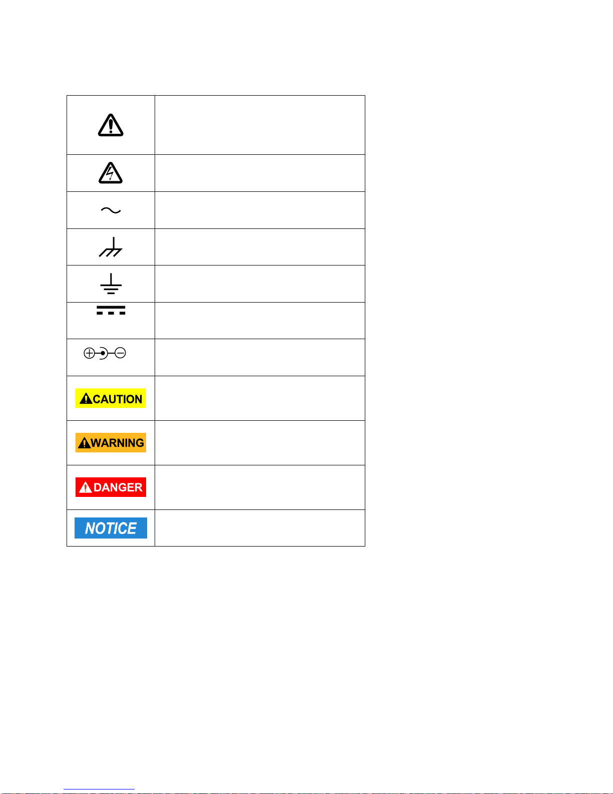
Refer to the user manual for warning
information to avoid hazard or personal
injury and prevent damage to
instrument.
Electric Shock hazard
Alternating current (AC)
Chassis (earth ground) symbol.
Ground terminal
DC Current
Indicates inside pin is positive (+),
outside is negative (-)
CAUTION indicates a hazardous
situation which, if not avoided, will
result in minor or moderate injury
WARNING indicates a hazardous
situation which, if not avoided, could
result in death or serious injury
DANGER indicates a hazardous situation
which, if not avoided, will result in death
or serious injury.
NOTICE is used to address practices not
related to physical injury.
Safety Symbols
8

This product is subject to Directive
2002/96/EC of the European Parliament
and the Council of the European Union
on waste electrical and electronic
equipment (WEEE), and in jurisdictions
adopting that Directive, is marked as
being put on the market after August
13, 2005, and should not be disposed of
as unsorted municipal waste. Please
utilize your local WEEE collection
facilities in the disposition of this
product and otherwise observe all
applicable requirements.
Operating Environment
0 °C to 40 °C
Storage Humidity
0 – 80% R.H.
Storage Environment
-20 °C to +50 °C
Pollution degree
Pollution degree 2
Compliance Statements
Disposal of Old Electrical & Electronic Equipment (Applicable in the European
Union and other European countries with separate collection systems)
Environmental Conditions
9

TABLE OF CONTENTS
Safety Summary ..................................................................................................................................... 1
Safety Guidelines ................................ ................................................................ ...................................................... 7
Safety Symbols ......................................................................................................................................................... 8
Compliance Statements ............................................................................................................................................ 9
TABLE OF CONTENTS ........................................................................................................................ 10
INTRODUCTION .................................................................................................................................... 13
PACKAGE CONTENTS .......................................................................................................................................... 13
FRONT PANEL OVERVIEW ................................................................................................................. 14
Front Panel Display Descriptions ............................................................................................................................ 14
Front Panel Buttons ................................................................................................................................................. 15
LCD DISPLAY OVERVIEW ..................................................................................................................................... 16
LCD Display Descriptions ................................................................ ........................................................................ 16
Special Display Indicators ....................................................................................................................................... 17
Test Port .................................................................................................................................................................. 18
POWERING INSTRUMENT ................................................................................................................... 19
Installing Battery ...................................................................................................................................................... 19
Connecting External Power Source ......................................................................................................................... 20
Low Battery Indication ............................................................................................................................................. 21
Backlit Display ......................................................................................................................................................... 21
When Using Battery Power ..................................................................................................................................................... 21
When Using External Power ................................................................................................................................................... 22
Charging Circuit ....................................................................................................................................................... 22
OPERATION INSTRUCTIONS .............................................................................................................. 23
Data Hold (HOLD) ................................................................................................................................................... 23
Turn On Data Hold .................................................................................................................................................................. 23
Turn Off Data Hold .................................................................................................................................................................. 23
Data Record Mode (REC) ....................................................................................................................................... 23
Enable Static Recording.......................................................................................................................................................... 23
Using Static Recording ........................................................................................................................................................... 23
Calibration (CAL) ..................................................................................................................................................... 24
Enter CAL Mode ..................................................................................................................................................................... 25
Open Cal ................................................................................................................................................................................ 25
Short Cal................................................................................................................................................................................. 25
Primary Parameter (PRI) ......................................................................................................................................... 26
Secondary Parameter (SEC) ................................................................................................................................... 27
Auto Detect Mode (AUTO) ...................................................................................................................................... 27
Enable Auto Detect Mode ....................................................................................................................................................... 27
Disable Auto LCR Mode.......................................................................................................................................................... 28
Test Frequency (FREQ) .......................................................................................................................................... 28
Selecting Frequency ............................................................................................................................................................... 28
Test Voltage Level (LEV) ........................................................................................................................................ 28
10

Measurement Rate (RATE) ..................................................................................................................................... 28
Parallel and Series Measurement Mode ................................................................................................................. 29
Default Settings ...................................................................................................................................................................... 29
Selecting Measurement Mode................................................................................................................................................. 29
Tolerance (TOL) ...................................................................................................................................................... 29
Tolerance Range .................................................................................................................................................................... 29
Setup Tolerance Mode ............................................................................................................................................................ 30
Disable Tolerance Mode ......................................................................................................................................................... 31
Utility Menu (UTIL) .................................................................................................................................................. 31
Entering Utility Menu ................................ ............................................................................................................................... 31
Configuration and Settings ................................................................................................................................ ...................... 31
Exit Utility Menu ...................................................................................................................................................................... 36
USB ......................................................................................................................................................................... 37
Automatic Fuse Detection ....................................................................................................................................... 37
QUICK START GUIDE .......................................................................................................................... 39
Inductance Measurement ........................................................................................................................................ 39
Capacitance Measurement...................................................................................................................................... 41
AC Resistance Measurement .................................................................................................................................. 42
Direct Current Resistance (DCR) Measurement ..................................................................................................... 43
Impedance Measurement ................................................................................................................................ ........ 44
REMOTE COMMUNICATION ............................................................................................................... 45
Connecting Instrument to PC .................................................................................................................................. 45
USB (Virtual COM) Configuration ............................................................................................................................ 46
USB Operation ........................................................................................................................................................ 46
Remote Mode ......................................................................................................................................................................... 46
Auto Fetching Mode ................................................................................................................................................................ 46
Command Protocols ................................................................................................................................................ 47
Overview of Command Type and Format ................................................................................................................................ 47
Common Command Format .................................................................................................................................................... 47
SCPI Command Format and Query Format ............................................................................................................................ 47
Termination Character ............................................................................................................................................................ 47
Responding Message ............................................................................................................................................................. 48
Data Types ............................................................................................................................................................................. 48
Command Reference .............................................................................................................................................................. 49
SCPI Commands .................................................................................................................................................................... 49
Error Codes ................................................................................................ ............................................................................ 54
SUPPLEMENTAL INFORMATION ....................................................................................................... 54
Selecting Test Frequency ................................................................................................................................ ........ 54
Capacitance ............................................................................................................................................................................ 54
Inductance .............................................................................................................................................................................. 54
Selecting Series or Parallel Mode ........................................................................................................................... 55
Capacitance ............................................................................................................................................................................ 55
Inductance .............................................................................................................................................................................. 55
Accuracy Discrepancies .......................................................................................................................................... 55
11

Capacitance ............................................................................................................................................................................ 56
Inductance .............................................................................................................................................................................. 56
Resistance .............................................................................................................................................................................. 56
Guard Terminal ....................................................................................................................................................... 56
SPECIFICATIONS ................................................................................................................................. 57
General Specifications ............................................................................................................................................ 57
Accuracy Specifications .......................................................................................................................................... 58
Testing Conditions: ................................................................................................................................................................. 58
Capacitance(C) and Dissipation (D) ........................................................................................................................................ 61
Impedance(Z)and Phase Angle
DCR ........................................................................................................................................................................................ 62
(θ)
................................................................................................................................. 62
MAINTENANCE ..................................................................................................................................... 64
Service .................................................................................................................................................................... 64
Cleaning .................................................................................................................................................................. 64
SERVICE INFORMATION ..................................................................................................................... 65
LIMITED WARRANTY ........................................................................................................................... 66
12

INTRODUCTION
B&K Precision’s 880 handheld LCR meter is designed for measuring the inductance, capacitance
and resistance of components. This LCR meter provides a 40,000-count primary parameter
reading and a secondary parameter reading with a resolution of 0.0001 with an accuracy of up
to 0.1%.
The meter provides direct and accurate measurements in series or parallel modes with
selectable testing frequencies, voltage levels and 4-wire measurements.
The auto range can rapidly display the measuring results and automatically choose the
desirable testing parameters in accordance with the components properties.
Front panel push buttons maximize the convenience of function and feature selection such as
data hold, maximum, minimum and average record mode, relative mode, tolerance sorting
mode, frequency and LCR selection.
The test data can be transferred to PC through a Mini USB connection, great for applications
that require data logging.
PACKAGE CONTENTS
The model was carefully inspected electrically and mechanically before shipment. After
unpacking all items from the shipping carton, check for any signs of physical damage that may
have occurred during transit. Report any damage to the shipping agent immediately. Save the
original packing carton for possible future shipment. The following items are included with
every model order:
880 handheld LCR meter
Quick start insert
Mini USB interface cable
Red & black banana to alligator test leads
TLBSB Shorting Plate
TL8KC1 Four terminal shielded Kelvin test lead
TL LCR SMD test lead
Battery charger
9V Ni-MH rechargeable battery (installed in meter)
Please locate the contents of the original packaging to ensure nothing is missing. If any of the
items are missing, please contact B&K Precision immediately.
13
1
2
3
4
5
6
7
8
9
11
12
13
14
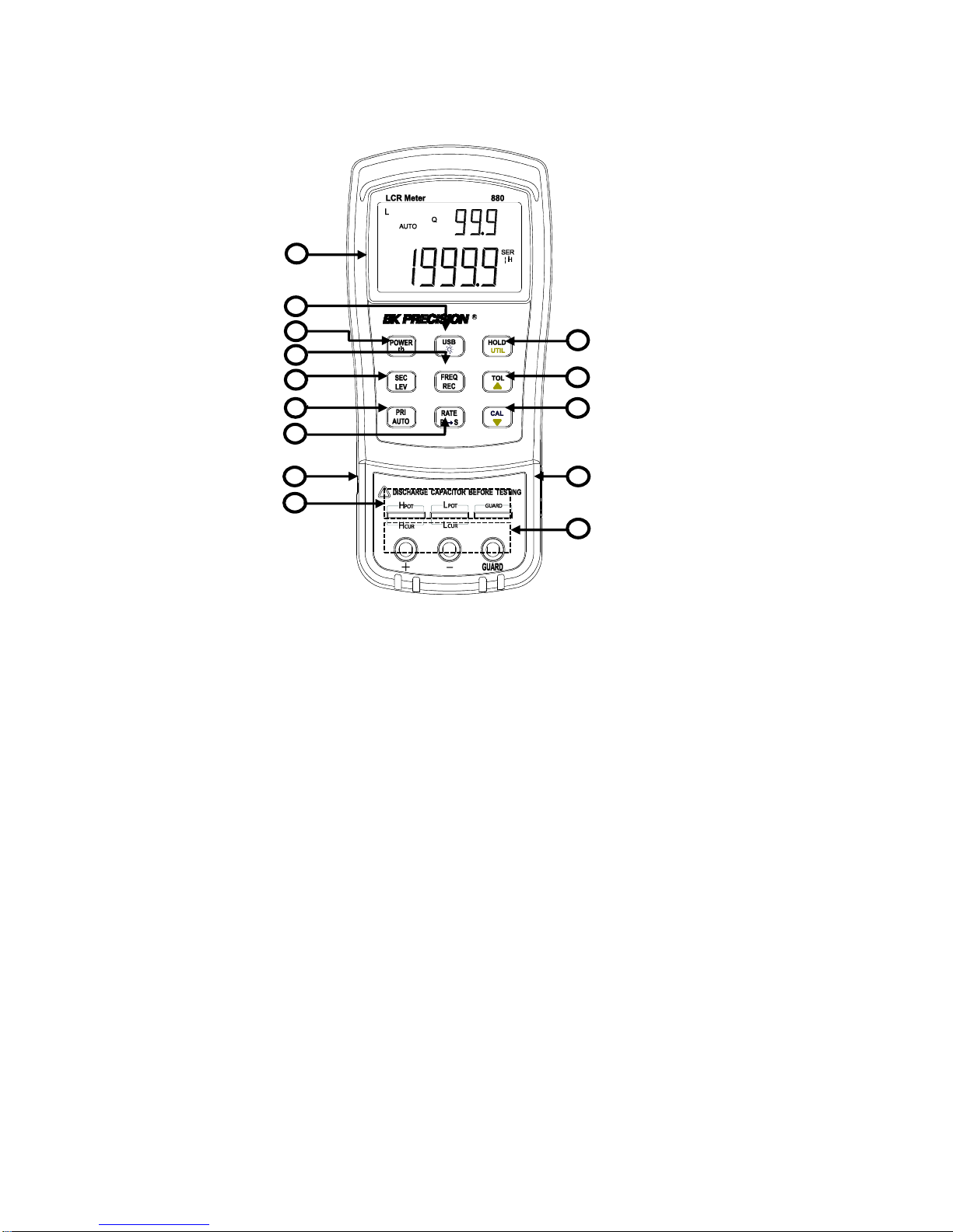
FRONT PANEL OVERVIEW
Figure 1 - Front Panel Display
Front Panel Display Descriptions
1. LCD display
2. USB communication / *Back light button
3. Power ON/OFF button
4. Frequency and record mode selection
5. Secondary display mode (D/Q//ESR, etc.)/ Test Level
6. Primary display mode (L/C/R/Z/DCR, etc.)/ auto LCR selection
7. Rate/equivalent mode selection
8. Standard mini USB port (for remote control)
9. 5-terminal test sockets (direct measurement on lead components or use of test fixture)
10. Hold mode/ utility menu
11. Tolerance mode/ utility arrow up key
12. Open/short calibration/ utility arrow down key
13. 12VDC external power input (use with an external power adapter)*
14. 3-terminal test jacks (for use of Banana plugs—Alligator clip Test Leads)
14

Note: Use with included power adapter only. Use with improper power adapters may
damage the instrument. Use power adapter only when there is a rechargeable battery
inserted or when there is no battery.
*WARNING: Before connecting an external power adapter, please check the battery
compartment in the rear side of the unit. If a battery is installed, be sure that the
polarity matches the (+) and (-) labels as indicated inside the battery compartment.
See “Installing Battery” section for details. DO NOT, at any time, connect an external
power adapter when a battery is installed incorrectly or is the wrong type. Doing so
will damage the instrument or the battery and void the instrument’s warranty.
Front Panel Buttons
With the exception of the power button, all front panel buttons have specific colored labels on
them. They are all marked in white, blue or yellow color. Each color has a specific
representation, as described below:
White—the primary function, these functions will be set or configured upon pressing the
button.
Blue—the secondary function, this function will be set or configured if that button is
pressed and held down for 2 seconds.
Yellow —the utility function, this function will be set or configured if the button is
pressed and held down for a couple of seconds. See “Utility Menu (UTIL)” section for details.
NOTE: In the button operational instructions, we will use the button name to express the
button operation without differentiating the type of button. The secondary function of each
button can be accessed by a long press of that button, indicated by a beep when the secondary
function has been accessed.
15
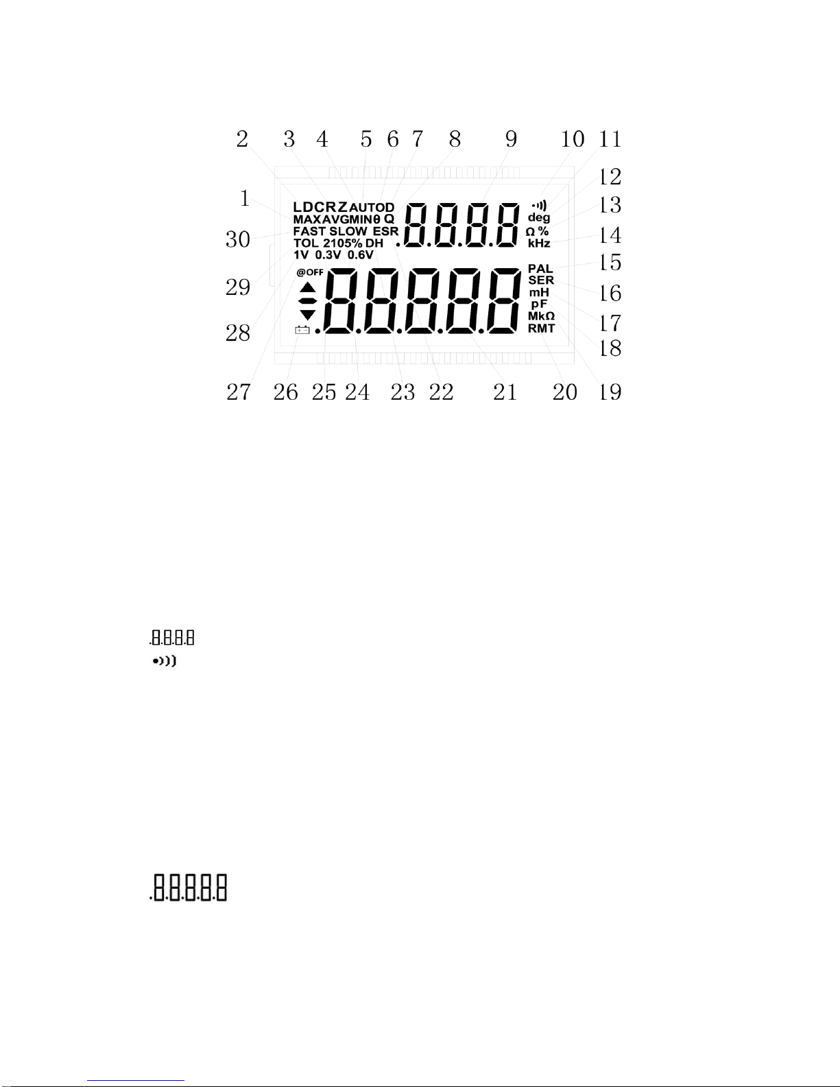
LCD DISPLAY OVERVIEW
Figure 2 - LCD Display
LCD Display Descriptions
1. MAX – Maximum reading indicator in the record mode
2. LDCRZ – Primary parameters display
3. AVG – Average reading indicator in the record mode
4. MIN – Minimum reading indicator in the record mode
5. AUTO – Automatic LCR indicator
6. – Phase angle indicator for secondary display
7. D – Dissipation indicator
8. Q – Quality factor indicator
9. – Secondary parameter display
10. – Beeper tone indicator for tolerance mode
11. deg – Phase angle (θ) units indicator
12. Ω – ESR(ohm) units indicator
13. % - Percentage indicator (in tolerance mode)
14. kHz – Frequency units indicator
15. PAL – Parallel mode indicator
16. SER – Series mode indicator
17. mH – Inductance units (L) indicator
18. pF –Capacitance units (C) indicator
19. MkΩ – Resistance(R) /impedance units indicator
20. RMT– Remote mode indicator
21. – Primary parameter display
22. ESR – Series mode indicator for secondary parameters
23. DH – Data hold indicator
24. SLOW – measuring rate indicator
25. 2105% - Limits indicator in tolerance mode
16

26. – Low battery/charging indicator
27. @OFF –Auto power-off indicator
28. 1V 0.6V 0.3V- Display test level
29. TOL –Tolerance mode indicator
30. FAST- Fast/Slow measuring rate indicator
Special Display Indicators
Indicates short connectors
Indicates open connectors
Error indication
Indicates calibration mode
Indicates damaged or open fuse
AD converter error
AD converter error
17
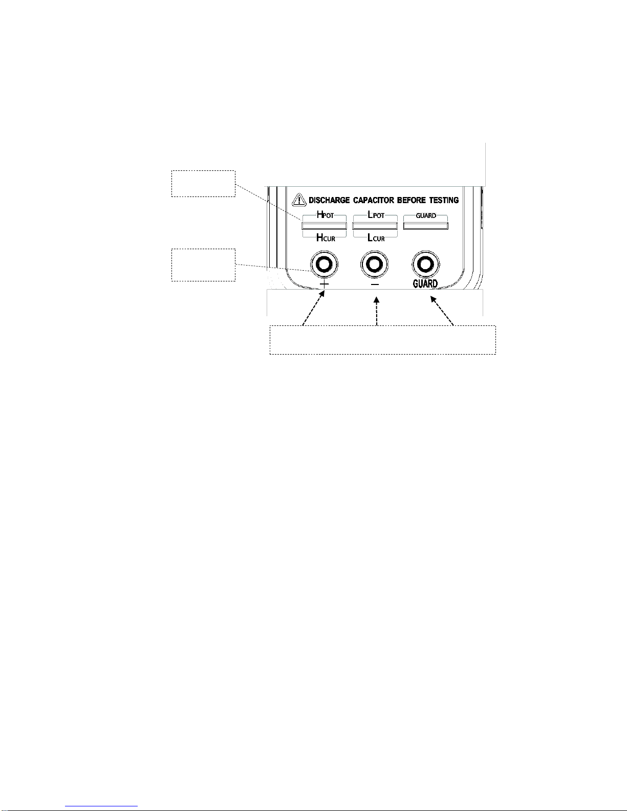
5-terminal
test slot
3-terminal
High Potential Low Potential Protect Potential
Test Port
The 880 is designed with two test ports: the 3-terminal port for convenience and a 5-terminal
port for higher accuracy.
test port
Figure 3 - Test Ports
The standard banana plugs allow the connection of banana to alligator test lead. This
configuration has lower testing accuracy when compared to the 5-terminal test port. The test
lead length should be kept as short as possible.
For a more accurate measurement when using external testing leads, the 880 LCR meter is
designed with a 5-terminal test port and exclusive test fixtures that provide a 4-wire connection
with a shield for increased measuring accuracy.
18

POWERING INSTRUMENT
Before beginning to operate the instrument, a power source is necessary for it to turn on.
There are two methods to power the instrument: Battery and external source.
Installing Battery
The 880 LCR meters can use a battery to provide power to the instrument so that it can be
portable.
The meters use a standard 9V size battery (or NEDA 1604, JIS006P, IEC6F22 carbon-zinc or
alkaline battery) or a rechargeable Ni-MH battery.
To install the battery:
1. Place the meter upside down. Open up the back-flip stand, and locate the screw that
tightens the battery compartment cover as indicated in Figure 4. Use a screwdriver to
unscrew and remove the cover.
2. Insert 9V battery into compartment. Note the positive (+) and negative (-) terminals as
indicated inside the battery compartment (See Figure 5). Be sure to insert the battery
with matching polarity.
Figure 4 - Back Cover
19

Figure 5 - Battery Compartment
3. Place the battery compartment cover piece by sliding it into the top slid first. Place
screw at the bottom of the cover piece and tighten down with a screwdriver.
4. Push and hold down the button for 2 seconds to turn on the instrument.
Connecting External Power Source
The 880 can also be powered using an external AC adapter. The model 880 comes with this
adapter included in the package.
Note: For external power, use AC adapter rated for output 12VDC, 150mA, center pin positive
4mm connector only.
WARNING: Use of the incorrect adapter may damage the instrument.
To connect the adapter, do the following:
1. If a battery is installed, please check the battery compartment again insuring the
polarity of the battery matches the polarity as indicated by the labels inside the
compartment. If it is not, please remove and insert the battery with matching polarity.
If a battery is not installed, continue to the next step.
WARNING: DO NOT, at any time, connect an external power adapter when:
The battery inside the unit is NOT rechargeable. Doing so will cause the battery to
burst, be damaged, or possibly catch fire.
A battery is installed incorrectly (reverse polarity or non-matching polarity to
indicator of battery compartment). Doing so will damage the instrument and void
its warranty.
2. Connect the AC adapter connector into the right side panel of the instrument. See
Figure 6 below.
3. Now, connect the AC Adapter socket into an electrical outlet.
4. Push and hold down the button for 2 seconds to turn on the instrument.
20
 Loading...