

Biostar TG31-A7 BIOS MANUAL

TG31 -A7 BIOS Manual
i
B IOS Setup.... ............ ............ ........................ ............ ............ .....................1
1 Main Menu...............................................................................................3
2 Adv anced Menu...... ............ ............ ............ ............ ............ ............ .........7
3 PCIPnP Menu........................................................................................18
4 Boot Men u..............................................................................................22
5 Chipset Menu.........................................................................................25
6 T-Series Menu........................................................................................29
7 Exit Menu...............................................................................................34

TG31 -A7 BIOS Manual
BIOS Setup
Introduction
The purpose of this manual is to describe the settings in the AMI BIOS Setup
program on this motherboard. The Setup program allows users to modify the basic
system configuration and save these settings to CMOS R AM. T he power of CMOS
RAM is supplied by a battery so that it retains the Setup information when the power
is turned off.
Basic Input-Output System (BIOS) determines what a computer can do without
acc essing programs from a disk. T his system controls most of the input and output
devices such as keyboard, mouse, serial ports and disk drives. BIOS activates at the
fi rst stag e o f the booting proc ess, loading and executing the operating system. S ome
additional features, such as virus and password protection or chipset fine-tuning
options are also included in BIOS .
T he rest of this manual will to guide you through the options and settings in B IOS
Setup.
Plug and Play Support
T his AMI BIOS supports the P lug and Play Version 1. 0A specific ation.
EPA Green PC Support
T his AMI BIOS supports Version 1.03 of the EPA Green PC specification.
APM Support
This AMI BIOS supports Version 1.1&1.2 of the Advanced Power Management
(AP M) speci fic ati on. Power m an agement fe atu res are i mplem ented vi a the Sy stem
Management Interrupt (SMI). Sleep and Suspend power management modes are
supported. Power to the hard disk dri ves and video monit ors can also be managed by
this AMI BIOS.
ACPI Supp ort
AMI ACPI BIOS support Version 1.0/2.0 of Advanced Configuration and Power
interface specifi cation (ACP I). It provides ASL code for pow er management and
device configuration capabilities as defined in the ACPI specification, developed by
Microso ft, Intel and T oshiba.
1
TG31 -A7 BIOS Manual
PCI Bus Support
T his AMI BIOS also supports Version 2.3 of the Intel PCI (Peripheral Component
Int erconn ect ) local b u s s p eci fic ati on .
DRA M Support
DDR2 S DRAM (Doubl e Data Rate II S ynchronous DRAM) is supported.
Su ppor t e d CP Us
T his AMI BIOS supports the Intel CPU.
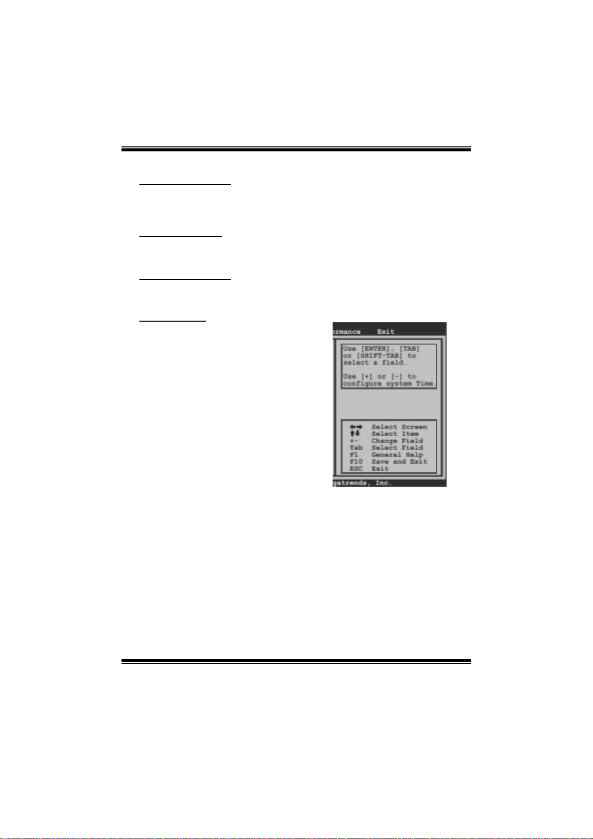
Using Setup
When starting up the computer, press
<Del> during the Power-On Self-Test
(POST) to enter the BIOS setup utility.
In the BIOS setup utility, you will see
General Help description at the top right
corner, and this is providing a brief
description of the selected item.
Navigation Keys for that particular menu
are at t he bottom right corner, and you can
us e these k eys to s ele ct item and change
the settings.
Notice
z T he default B IOS settings apply for most conditions to ensure optimum per formance
of the motherboard. If the system becomes unstable after changing any settings,
please load the default settings to ensure system’s compatibility and stability. Use
Load S etup Default under the Exit Menu.
z For better system perform ance, the BIOS firmware is being continuously updated.
T he BIOS information descri bed i n this manual is for your reference onl y. The actual
BIOS i nformati on and settings on board may be slightly different from this manual.
z T he content of this manual is subject to be changed without notice. W e will not be
responsible for any m istakes found in this user’s manual and any system damage that
may be caused by wrong-settings.
General Help
Navigati on Keys
2
TG31 -A7 BIOS Manual
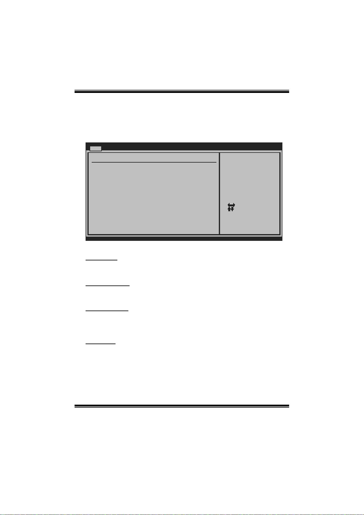
1 M ain Menu
Once you enter AMI BIOS Setup Utility, the Main Menu will appear on the screen
providing an overview of the basic system i nform ation.
Main Advan ced PCIPnP Boot Chipset T-Series
System Overvie w
AMI BIOS
Version :01. 01.01
Build Date:01/ 01/08
System Time 00
System Date [Tue 01/01/2008]
Floppy A
> IDE Configur ation
vxx .xx (C)Copyright 1985-200x, American Megatrends, Inc.
AM I BIOS
BIOS SETU P UTILITY
[ :0 0:00]
Exit
Use [ENTER], [TAB]
or [SHIFT-TAB] to
select a field.
Use [+] or [-] to
configure system Time.
Se lect Screen
Se lect Item
Ch ange Field
+-
Se lect Field
Tab
Ge neral Help
F1
Sa ve and Exit
F10
Exit
ESC
Shows s ystem information including B IOS version, built date, etc.
System Time
Set the system internal clock.
System Date
Set the system date. Note that the ‘Day’ automatically changes when you set the
date.
Floppy A
Select the type of fl oppy dis k drive installed in your syst em.
Options: 360K, 5. 25 in / 1. 2M, 5.25 in / 720K, 3. 5 in / 1.44M, 3.5 in /
2.88M, 3.5 in / None
3

TG31 -A7 BIOS Manual
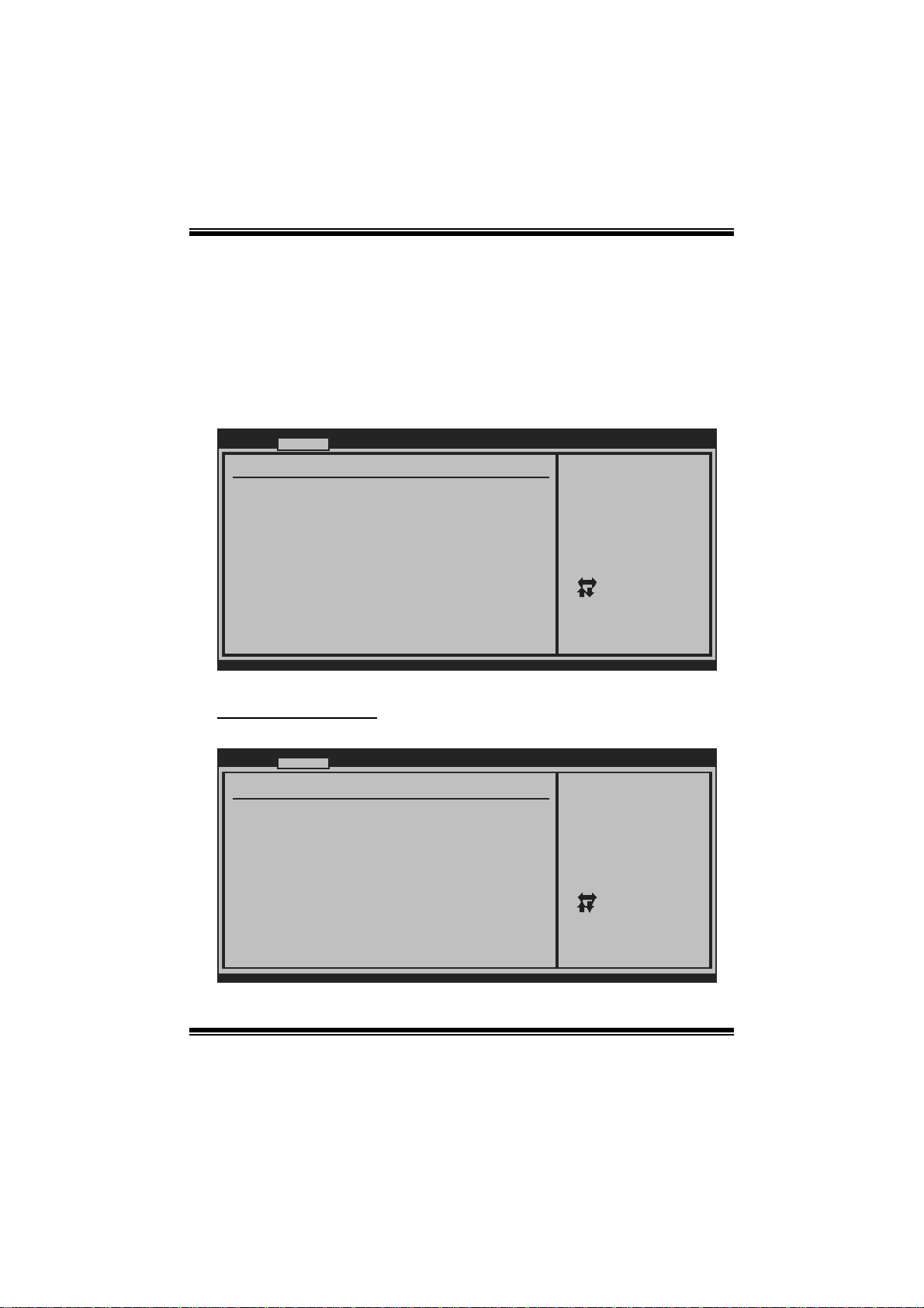
IDE Configuration
Th e BIOS wi ll au t o m ati cal l y detect t h e presen c e o f ID E / SAT A d evices . T her e i s a
su b-menu fo r each IDE/ SAT A devi ce. Select a devi ce and p ress <Ent er> t o enter
the sub-menu of detailed opti ons.
Main
IDE Confugurat ion
ATA/IDE Config uration [Enh anced]
Configure SA TA Channels [Bef ore PATA]
> Primary IDE Master
> Primary IDE Slave
> Secondary ID E Master
> Secondary ID E Slave
> Third IDE Ma ster
> Third IDE Sl ave
Hard Disk Writ e Protect [Dis abled]
IDE Detect Tim e Out (Sec) [35]
BIOS SETU P UTILITY
Options
Disabled
Compatible
Enhanced
Se lect Screen
Se lect Item
Go to Sub Screen
Enter
Ge neral Help
F1
Sa ve and Exit
F10
Exit
ESC
vxx .xx (C)Copyright 1985-200x, American Megatrends, Inc.
ATA/IDE Confi guration
T his i tem allows you to control the onboard IDE controller.
Options: Enhanced (Default) / Compatible / Disabled
Confi gure SATA Channels
T his i tem allows you to control the S AT A channel confi guration sequenc e..
Options: Befo re PATA (De fault)
4

TG31 -A7 BIOS Manual
Pri mary/Secondary/Third IDE Ma ster/ Slav e
Main
Primary IDE Master
Device :
Type [Auto]
LBA/Large Mode [Auto]
Block (Multi-Sector Transfer)[Auto]
PIO Mode [Auto]
DMA Mode [Auto]
S.M.A.R.T [Auto]
32Bit Data Transfer [Enabled]
vxx.xx (C)Copyright 1985-200x, American Megatrends, Inc.
BIOS SETUP UTILITY
Select the type
of device connected
to the system.
Select Screen
Select Item
Change Option
+-
General Help
F1
Save and Exit
F10
Exit
ESC
The BIOS detects the information and values of respective devices, and these
information and values are shown below t o the name of the sub-menu.
Type
Select the type of the IDE/SATA drive.
Options: Auto (Default) / CDROM / ARMD / Not Installed
LBA/Large Mode
Enable or disable the LBA mode.
Options: Auto (Default) / Disabled
Block (Multi-Sector Transfer)
En able o r d i s ab l e m u l ti -s ect o r t ran s fer.
Options: Auto (Default) / Disabled
PIO Mode
Select the P IO mode.
Options: Auto (Default) / 0 / 1 / 2 / 3 / 4
DMA Mode
Select the DMA mode.
Options: Auto (Default) / Disabled
5

TG31 -A7 BIOS Manual
S.M.A.R.T
Set the Smart Monitoring, Analysis, and Reporting Technology.
Options: Auto (Default) / Disabled / Enabled
32Bit Data Transfer
Enable or disable 32-bit data transfer.
Options: Enabled (Default) / Disabled
Har d Disk Wri te Protec t
Disable or enable device write protection. This will be effective only if the device
is accessed through B IOS .
Options: Disabled (De fault) / Enabled
IDE Detect Time Out (Sec)
Select the time out value for detecting IDE/SATA devices.
Options: 35 (De fault) / 30 / 25 / 20 / 15 / 10 / 5 / 0
6
TG31 -A7 BIOS Manual
2 Advanced Menu
T he Advanced Menu allows you to configure the sett ings of C PU, S uper I/ O, P ower
Management, and other system devices.
Notice
z Beware of that setting inappropriate values in items of this menu may cause
system to m alfunction.
Main Advan ced PCIPnP Boot Chipset T-Series
WARNING: Setti ng wrong values in below sections
may c ause system to malf unction.
> CPU Configur ation
> SuperIO Conf iguration
> Hardware Hea lth Configuration
> Smart Fan Co nfiguration
> Power Config uration
> USB Configur ation
BIOS SETU P UTILITY
Configure CPU.Advanced Setti ngs
Exit
Se lect Screen
Se lect Item
Go to Sub Screen
Enter
Ge neral Help
F1
Sa ve and Exit
F10
Exit
ESC
vxx .xx (C)Copyright 1985-200x, American Megatrends, Inc.
CPU Configurati on
T his item shows the C PU information that the BIOS automatically detects.
Advan ced
Configure adva nced CPU settings
Module Version :xx.xx
Manufacturer:I ntel
Frequency :
FSB Speed :
Cache L1 :
Cache L2 :
Ratio Actual V alue:
Hardware Prefe tcher [En abled]
C1E Support [Au to]
Adjacent Cache Line Prefetch [En abled]
Max CPUID Valu e Limit [Di sabled]
Intel(R) Virtu alization Tech [En abled]
Execute-Disabl e Bit Capability[En abled]
Single Logical Processor Mode [Di sabled]
Intel(R) Speed Step(tm) tech [En abled]
vxx .xx (C)Copyright 1985-200x, American Megatrends, Inc.
BIOS SETU P UTILITY
7
This should be enabled
in order to enable or
disable the Hardware
Prefetcher Disable
Feature.
Se lect Screen
Se lect Item
Ch ange Option
+-
Ge neral Help
F1
Sa ve and Exit
F10
Exit
ESC

TG31 -A7 BIOS Manual
Hardware Prefetcher
Th e proces s o r h as a h ardw are pref et cher t h at au t omat i cal ly anal y zes it s req u irem ents
and pre fet ch es dat a an d in s t ru ct ion s fro m th e m emo ry i n t o th e Lev el 2 cach e t h at are
likely to be required in the near future. This reduces the latency associated with
m emory read s.
Options: Enabled (Default) / Disabled
C1E Support
T his item allows you to configur e the Enhanced Halt State (C1E) fun ction, which
may reduce the power consumption of your system when the system is idle.
Options: Auto (Default) / Disabled
Adj acent Cache Line Prefetch
The processor has a hardware adjacent cache line prefet ch mechanism that
aut o mat i cal l y fet ch es an ext ra 6 4-by t e cach e l i n e whenev er the p ro cesso r req uest s for
a 64-byte cache line. This reduces cache latency by making the next cache line
immediately available if the processor requires it as well.
Options: Enabled (Default) / Disabled
M ax CPUI D Va l ue Li m i t
When the computer is booted up, the operating system executes the CPUID
instruction to identify the processor and its capabilities. Befo re it can do so, it must
first query the processor to find out the highest input value CPUID recognizes. T his
determines the kind of basic information CP UID can provide the operating system .
Options: Disabled (De fault) / Enabled
Inte l(R) Virtualiza tion Te c h
Virtualization Technology can virtually separate your system resource into several
parts, thus enhance the performance when running virtual machines or multi
interfa ce systems.
Options: Enabled (Default) / Disabled
Execute-Disable Bit Capability
T his i tem allows you to configure th e Execut e Disabled Bit function, which protects
your sys tem from buffer over flow attacks.
Options: Enabled (Default) / Disabled
8

TG31 -A7 BIOS Manual
Si ngle Logica l Process or Mode
T his item controls multi-processing fun ction for multi-core processors.
Options: Disabled (De fault) / Enabled
In tel(R) Speed Step (tm) Tech
This item allows you to enable SpeedStep technology for better power saving.
SpeedStep is a technology built into some Intel processors that allows the clock
sp eed of the proces s o r to b e d y nami cal l y chang ed b y s oftware.
Options: Enabled (Default) / Disabled
S uperI O Co nfig urati on
Advan ced
Configure ITE8 718 Super IO Chipse t
Onboard Floppy Controller [Ena bled]
Serial Port1 A ddress [3F8 /IRQ4]
Parallel Port Address [378 ]
Parallel Por t Mode [Nor mal]
Parallel Por t IRQ [IRQ 7]
Keyboard Power On [Dis abled]
Mouse PowerOn [Dis abled]
Restore on AC Power Loss [Pow er Off]
BIOS SETU P UTILITY
Allows BIOS to Enable
or Disable Floppy
Controller
Se lect Screen
Se lect Item
Ch ange Option
+-
Ge neral Help
F1
Sa ve and Exit
F10
Exit
ESC
vxx .xx (C)Copyright 1985-200x, American Megatrends, Inc.
Onboard Floppy Controller
Select enabled if your system has a floppy disk controller (FDC) installed on the
system board and you wish to use it. If you installed another F DC or the system uses
no fl oppy drive, select dis abled in this field.
Options: Enabled (Default) / Disabled
Serial Port1 Address
Select an address and corresponding i nterrupt fo r the first and s econd seri al ports.
Options: 3F8/IRQ4 (Default) / 2F8/IRQ3 / 3E8/IR Q4 / 2E8/IR Q3 / Auto / Di sabled
9

TG31 -A7 BIOS Manual
Parallel Port Address
Th i s i t em al l ows y o u to det erm ine acces s onboard parall el port controller with which
I/O Address.
Options: 378 (De fault) / 278 / 3BC / Disabled
Parallel Port M ode
T his i tem allows you to determine how the parallel port shoul d function.
Options: Normal (Default) Using Parallel port as Standard Printer Port.
EPP Using Parallel Port as Enhanced Parallel Port.
ECP Using Parallel port as Extended C apabilities Port.
ECP + EPP Using Parallel port as ECP & EPP mode.
Parallel P ort IRQ
T his i tem allows you to select the IR Q for t he onboard parallel port.
Options: IRQ7 (Default) / IR Q5 / Disabled
Keyboard PowerO n
T his i tem allows you to control the keyboard power on function.
Options: Disabled (De fault) / Enabled
Mouse PowerOn
T his i tem allows you to control the mouse power on function.
Options: Disabled (De fault) / Enabled
Restore on AC Power Loss
T his setting s pecifies how your system shoul d behave aft e r a power fail or interrupts
occurs. By choosing Disabled will leave the computer in the power off state.
Choosing Enabled will restore the system to the status before power failure or
interrupt occurs.
Options: Power O ff (Default) / P ower ON / Last S tate
10

TG31 -A7 BIOS Manual
Hardware Health C onfiguration
T his i tem shows t he system temperature, fan speed, and voltage information.
Advan ced
Hardware Healt h Configuration
H/W Health Fun ction [Ena bled]
Shutdown Tempe rature Function[Dis abled]
CPU Temperatur e
CPU FAN Speed
SYS FAN Speed
NB FAN Speed
CPU Vcore
Chipset Voltag e
+3.30V
+5.00V
+12.0V
FSB Voltage
Memory Voltage
5V(SB)
Voltage Batter y
vxx .xx (C)Copyright 1985-200x, American Megatrends, Inc.
H/W Health Function
If you computer contains a monitoring system, it will show PC health status during
P OST s t ag e.
Options: Enabled (Default) / Disabled
Shutdown Te m pe r ature Func tion
BIOS SETU P UTILITY
Enables Hardware
Health Monitoring
Device.
Se lect Screen
Se lect Item
Ch ange Option
+-
Ge neral Help
F1
Sa ve and Exit
F10
Exit
ESC
T his item allows you to set up the CPU shutdown Temperature. This item is only
effecti ve under Wi ndows 98 ACPI m ode.
Options: Disabled (De fault) / 60℃/ 140℉ / 65℃/149℉ / 7 0 ℃/158℉ / 75℃/167℉
/ 80℃/176℉ / 85℃/185℉ / 90℃/194℉
11
 Loading...