

Page 1

TForce 945P SE Setup Manual
FCC Information and Copyright
This equipment has been tested and found to comply with the limits of a Class
B digital device, purs uant to Part 15 of the FCC Rules. These limits are designed
to provide reasonable protec tion against harm ful interference in a residential
installation. T his equipment generates, uses and can radiate radio frequency
energy and, if not installed and used in accordance with the instructions, may
cause harmful interference to radio communications. There is no guarantee
that i nterfe rence wil l not occ u r in a particula r ins talla tio n .
The ve n dor ma kes no rep res e n ta tio ns or warran ties with r espec t to t he
contents here and specially disclaims any implied warranties of merchantability
o r fi tn ess fo r any p u rp os e . F u rt he r t he ve nd o r res e rves the ri g ht to r ev is e t h is
publication and to make c hanges to the contents here without obligation to
notify any party beforehand.
D uplicati on of this publicat ion, i n part o r in wh ole , is not allo wed wi t hout fi rst
obtaining the vendor’s approval in writing.
The content of this user’s manual is subject to be changed without notice and
we will not be responsible fo r a ny mis takes fo und in this user’s manual. All the
brand and produc t names are trademarks of their respective companies .
Page 2

Table of Contents
Chapter 1: Intro duction ............................................. 1
1.1 Be fo re Yo u Start................................................................... 1
1.2 Package Checklist................................................................ 1
1.3 Motherboard Features.......................................................... 2
1.4 Rear Panel Connectors (Ver 6.x)............................................ 4
1.5 Rear Panel Connectors (Ver 5.x)............................................ 4
1.6 Mothe rboard Layout (for Ver 6.x ).......................................... 5
1.7 Motherboard Layout (for Ver 5.x ).......................................... 6
Chapter 2: Hardware Installation.............................. 7
2.1 Installing Central Processing Unit (CPU)................................ 7
2.2 FAN Headers........................................................................ 9
2.3 Installing System Memory.....................................................10
2.4 Connectors and Slots ............................................................12
Chapter 3: Headers & Jumpers Setup .....................14
3.1 How to Set up J umpers..........................................................14
3.2 Detail Se ttings.....................................................................14
Chapter 4: O verClock Quick Guide ..........................19
4.1 T-Power Introduction...........................................................19
4.2 T-Power BIOS Feature .........................................................20
4.3 T-Powe r Windows Fe ature...................................................28
Chapter 5: Useful Hel p .............................................37
5.1 Driver Installation Note .......................................................37
5.2 Award BIOS Bee p Code........................................................38
5.3 Extra Information................................................................38
5.4 Troubleshooting...................................................................40
Appende ncies: SPEC In Other La nguage ................42
German................................................................................................42
France..................................................................................................44
Italian..................................................................................................46
Spanish ................................................................................................48
Portuguese...........................................................................................50
Polish...................................................................................................52
RUSSIAN...............................................................................................54
ARABIC................................................................................................56
JAPANESE............................................................................................58
Page 3

T Force 94 5P SE
CHAPTER 1: INTRODUCTION
1.1 BEFORE YOU START
Tha nk you fo r choo sing our p roduct. Be fo re you s tart installing the
mo the rboa rd, plea se make su re you follo w the ins tructio ns belo w:
Prepare a dry and stable working environment with
s uf fi cie nt ligh ting .
Always disconnect the computer from power outlet
be fo re ope ra tion .
Befo re you take the mo the rbo a rd o u t f rom a n ti -s ta ti c
bag, ground yourself properly by touching any safely
grounde d ap pliance, or use grounded wris t s trap to
remove the static charge.
Avo id tou ch ing the com pone nts on mo the rbo a rd o r the
rea r side of the boa rd unless ne cessary. Hold the boa rd
on the edge , do no t try to be nd or flex the boa rd.
Do no t leave an y unfas tened sma ll pa rts inside the
case after installation. Loose parts will cause short
circuits which ma y damage the equ ipment.
Keep the computer from dangerous area, such as heat
sou rce, humid a ir and wa ter.
1.2 PACKAGE CHECKLIST
z FDD Cable X 1
z HDD Cable X 1
z Use r’s Ma nua l X 1
z Se ria l ATA Cab le X 1
z Se ria l ATA Po we r Switch Cab le X 1
z Fully Setup Driver CD X 1
z Rear I/O Panel for ATX Case X 1
z USB 2.0 Cable X1 (optional)
z S/PDIF Cable X 1 (optional)
1
Page 4

Motherboard Manual
1.3 MOTHERBOARD FEAT URES
Ve r 6. x Ve r 5. x
LGA 77 5
Intel Core2Duo / Pentium 4 / Pentium D /
Celeron D pr ocessor up to 3.8 GHz
CPU
FS B 533 / 800 / 106 6 MHz 533 / 800 / 106 6 MHz
Chipset
Super I/O
Main
Memory
IDE
SATA
10/ 100
LAN
Sound
Codec
Suppor ts Hy per -Thre adin g
Execute Dis able Bit
Enha nced Intel Sp eedStep
Extende d Memor y 64 Tech nolog y
Int el 9 45P
Intel ICH7
ITE I T 8718F
H/W Monitor
Fan S pee d Co nt roller
ITE' s "Smart G uardia n" fu nct ion
DIMM Slots x 4
Eac h DIM M sup port s 256/ 512M B & 1GB
DDR2
Max Memory C apicity 4GB
Dual Channel Mode DDR2 memory module
Supports D DR 2 533 / 667
Integrated IDE Controller
Ultra DMA 33~100 Bus Master Mode
support s PIO Mo de 0~4,
Integrated Seri al ATA Controller
Data transfer rates up to 3.0 Gb/s.
SATA Version 2.0 specification compliant.
Realtek RTL 8110SC
10 / 100 Mb/s and 1Gb/s auto negotiation
Half / Full duplex capability
AL C 861V D
5.1 cha nnels a udio out
Intel Hig h-De finition Audi o support
LGA 77 5
Intel Core2Duo / Pentium 4 / Pentium D /
Celeron D pr ocessor up to 3.8 GHz
Suppor ts Hy per -Thre adin g
Execute Dis able Bit
Enha nced Intel Sp eedStep
Extende d Memor y 64 Tech nolog y
Int el 9 45P
Intel ICH7
ITE I T 8718F
H/W Monitor
Fan S pee d Co nt roller
ITE' s "Smart G uardia n" fu nct ion
DIMM Slots x 4
Eac h DIM M sup port s 256/ 512M B & 1GB
DDR2
Max Memory C apicity 4GB
Dual Channel Mode DDR2 memory module
Supports D DR 2 533 / 667
Integrated IDE Controller
Ultra DMA 33~100 Bus Master Mode
support s PIO Mo de 0~4,
Integrated Seri al ATA Controller
Data transfer rates up to 3.0 Gb/s.
SATA Version 2.0 specification compliant.
Realtek RTL 8110SC
10 / 100 Mb/s and 1Gb/s auto negotiation
Half / Full duplex capability
AL C 888
7.1 cha nnels a udio out
Intel Hig h-De finition Audi o support
2
Page 5

T Force 94 5P SE
g
g
Ve r 6. x Ve r 5. x
PCI Express x 16 slot x1 PCI Express x 16 slot x1
Slots
On Board
Connector
Back Panel
I/O
Board Size 205 (W) x 30 5 (L) mm 205 (W) x 30 5 (L) mm
OS
Suppor t
PCI Express x 1 slot x2 PCI Express x 1 slot x2
PCI s lot x3 PCI s lot x3
Floppy connector x1 Floppy connector x1
IDE C o nnect or x1 IDE C o nnector x1
SATA Connector x4 SATA Connector x4
Front Pa nel C o nnect or x1 Fr ont Pa nel C o nnect or x1
Front Audi o Connect or x1 Front A udi o Connector x1
CD-in C o nnect or x1 CD-in Co nnector x1
S/PDIF o ut connector x1 S/PDIF o ut connector x1
CPU Fan hea der x1 CPU Fan header x1
Sys tem Fan hea der x1 Sys t em F an hea der x1
Chassis open header (optional) x1 Chassis open header (optional) x1
Clear CMOS header x1 Clear CMOS head er x1
USB connector x2 USB connector x2
Power Connector (24pi n) x1 Power Connector (24pi n) x1
Power Connector (4pin) x1 Power Connector (4pin) x1
PS/2 Keyb oard x1
PS/2 Mo use x1
Serial Port x1
Printer Port x1
LAN port x1
USB Port x4
Audio Jack x3
Windows 2000 / XP / VISTA
Biostar Reserves the ri
support for any OS with or without notice.
ht t o add or remo ve
PS/2 Keyb oard x1
PS/2 Mo use x1
Serial Port x1
Printer Port x1
LAN port x1
USB Port x4
Audio Jack x6
Windows 2000 / XP / VISTA
Biostar Reserves t he ri
support for any OS with or without notice.
ht to add or remove
3
Page 6
Motherboard Manual
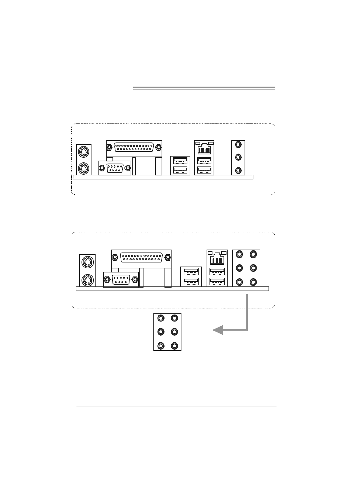
1.4 REAR PANEL CONNECT ORS (V ER 6.X)
PS/2
Mouse
PS/ 2
Keyboard
Printer Port
COM1
1.5 REAR PANEL CONNECT ORS (V ER 5.X)
PS/2
Mouse
PS/ 2
Keyboard
Pr i nt e r P o r t
COM1
LAN
Lin e In /
Surround
Line Out
Mic In 1/
Bass/ Center
USBX2USBX2
LA N
USB X2USBX2
Center
Re ar
Side
Since t he au di o c hip s upports I ntel Hig h D e fini ti on Audi o Sp ecificatio n, the fu nctio n o f e ach
audi o jac k c an be defi ne d by soft war e. T h e i n put / out put fu nctio n of eac h audi o j ac k l i s t ed
abo ve re pr ese nts t he def ault setti ng . Ho we ver, wh en c onnecti ng e xter nal micr op hone t o the
audi o port, pl eas e us e t he Li ne In (blue) an d Mic In (Pi nk) au dio jac k.
4
Line In
Line Out
Mic I n
Page 7
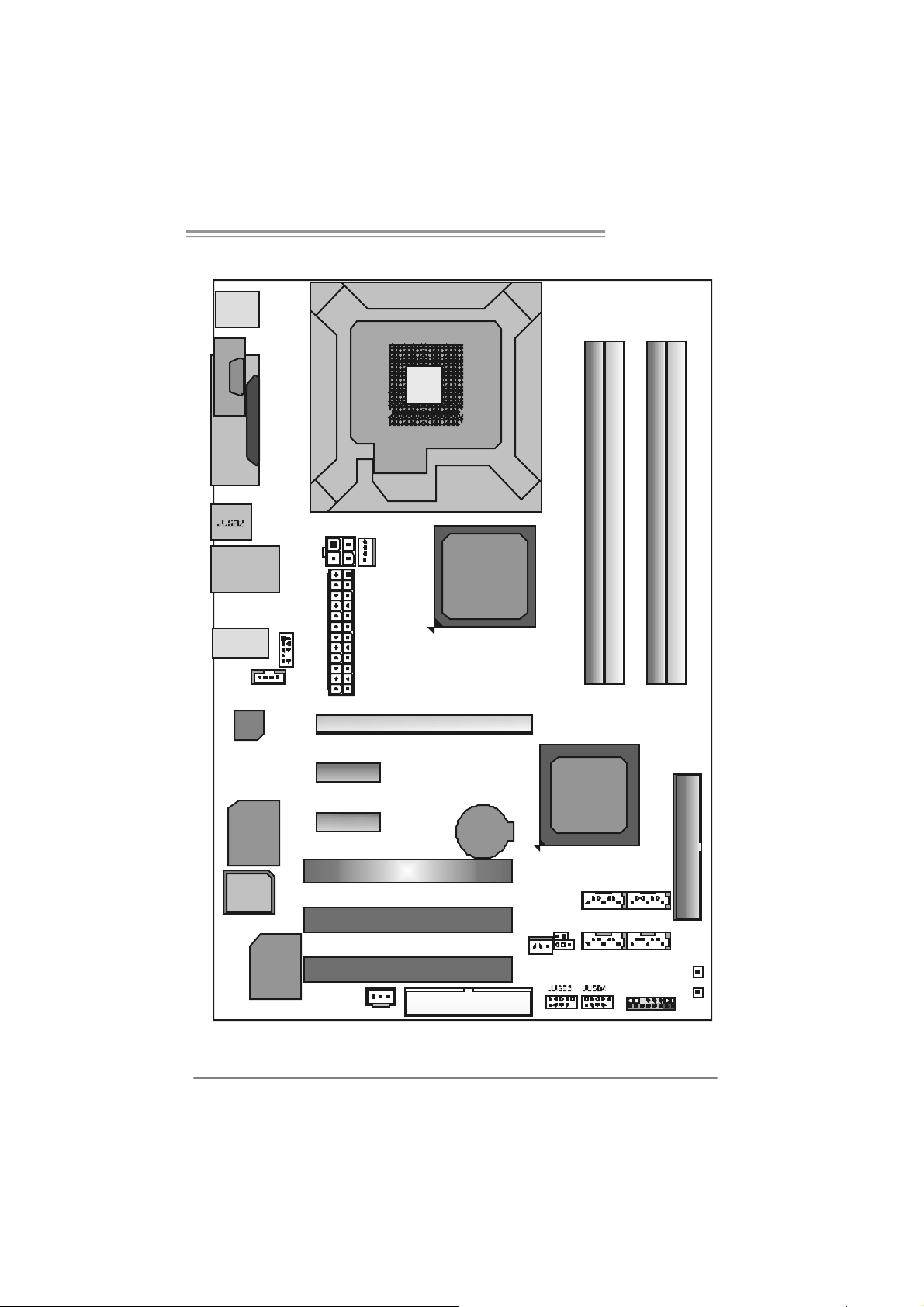
1.6 MOTHERBOARD LAYOUT (FOR VER 6.X)
)
_
JKBMS1
T Force 94 5P SE
C
O
J
M
C
1
O
M
1
JPRNT1
JRJ45USB1
JA UDIO1
JCDIN1
Codec
Super
I/O
BIO S
JAUDIOF1
JATX PWR 2
PEX1_1
PEX1_2
JC FAN1
JATX PW R1
LGA7 75
CPU1
PE X16_1
PCI1
PCI 2
Intel
945P
BAT1
Intel
ICH7
JC I1(Optional
DDR2_A1
SATA1
DDR2_B1
DDR2_ A2
DDR2_ B2
IDE1
SATA3
JCMOS1
SATA2
10 /100 LA N
JSP DI F
OU T
PCI 3
JSFAN1
FDD1
SATA4
JPA NEL 1
PW RSW1
RST SW1
Not e: ■ repre sents the 1st pin.
5
Page 8
Motherboard Manual
)
_
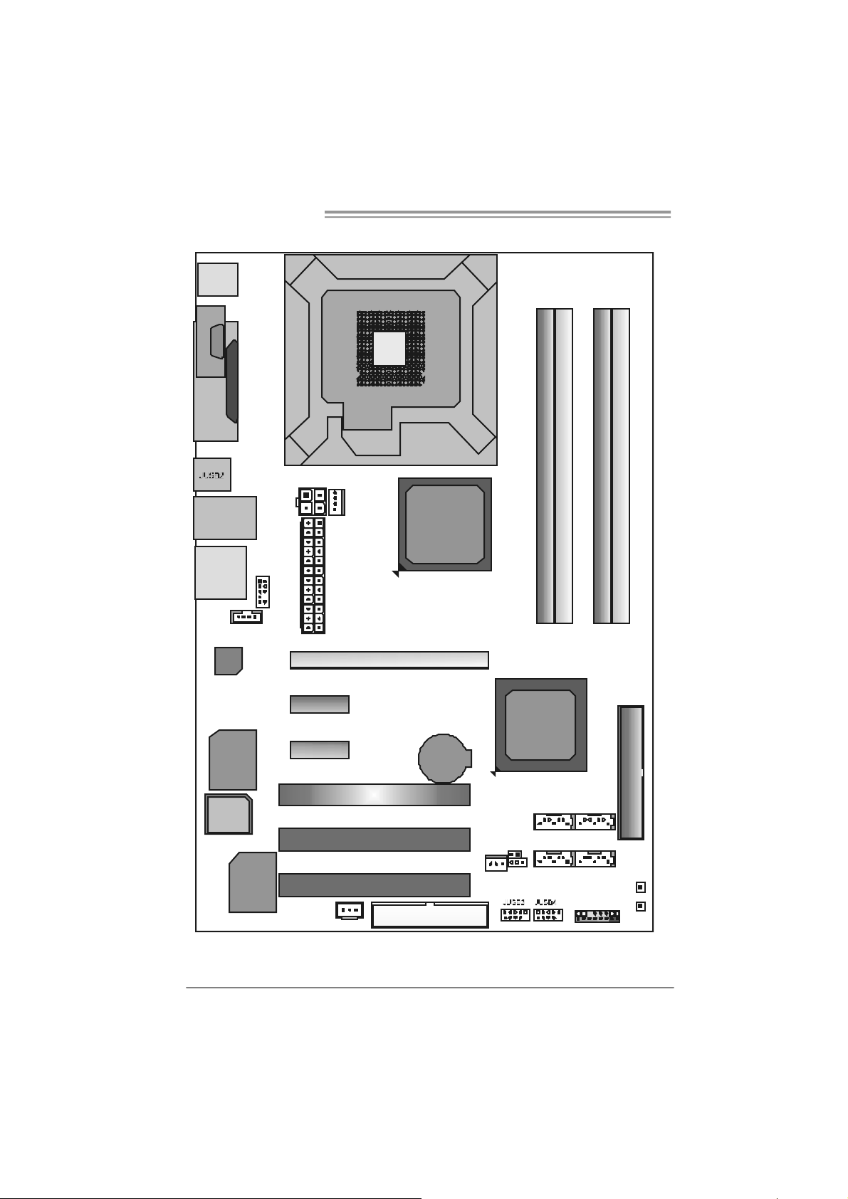
1.7 MOTHERBOARD LAYOUT (FOR VER 5.X)
JKBMS1
CO M1JC OM 1
JPRNT1
JRJ45USB1
JAUDIO 2
JCDIN1
Codec
Super
I/O
BIO S
JAUDIOF1
JATX PWR2
PEX1_1
PEX1_2
JCFAN1
JATX PW R1
LGA7 75
CPU1
PE X16_1
PCI1
PCI 2
Intel
945P
BAT1
Intel
ICH7
JCI 1(Optional
DDR2_A1
SATA1
DDR2_B1
DDR2_ A2
DDR2_ B2
IDE1
SATA3
JCMOS1
SATA2
10 /100 LA N
JSP DI F
OUT
PCI 3
JSFAN1
FDD1
SATA4
JPA NEL1
PW RSW1
RST SW1
Not e: ■ repre sents the 1st pin.
6
Page 9
T Force 94 5P SE
CHAPTER 2: HARDWARE INSTALLATION
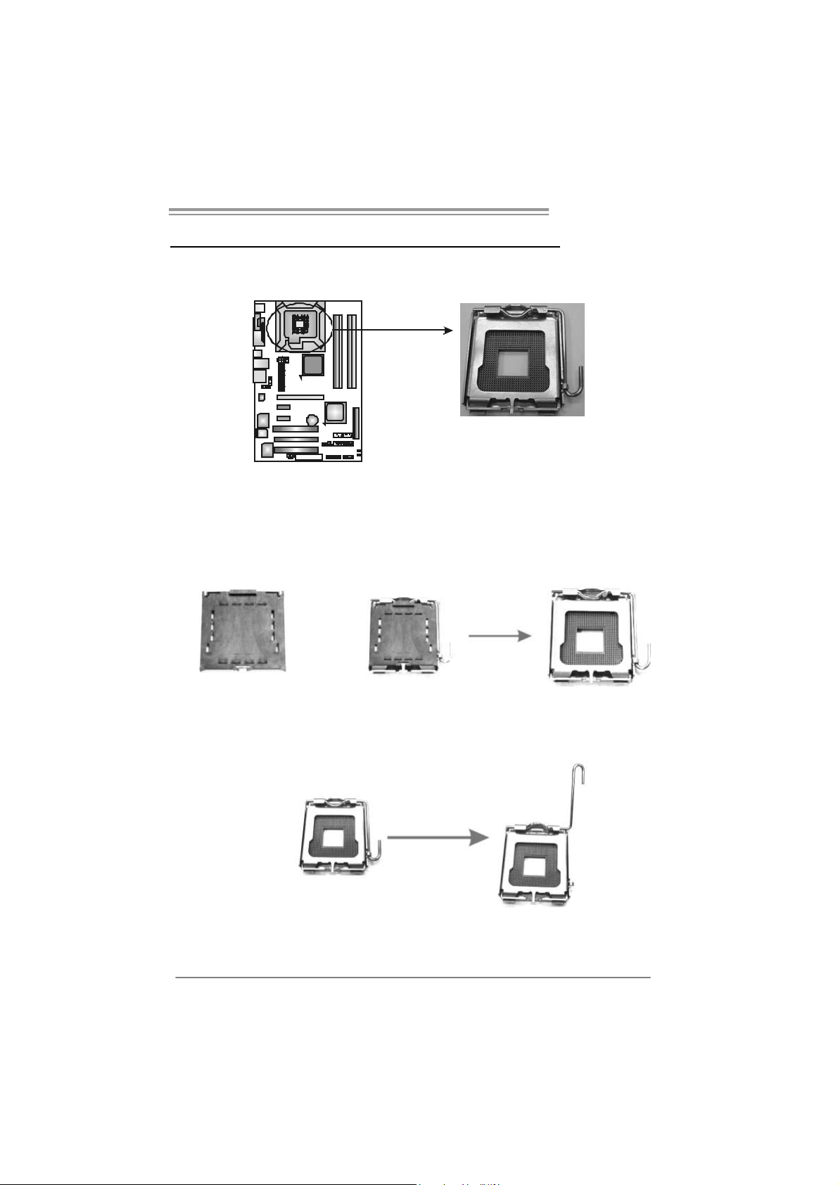
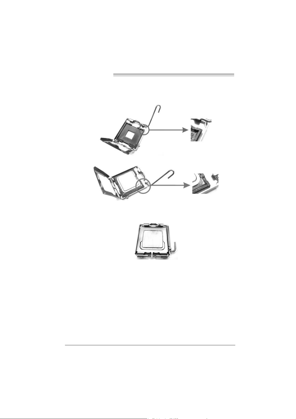
2.1 INST ALLING CENTRAL PROCESSING UNIT (CPU)
Special Notice:
Remove Pin Cap before installation, and make good preservation
for future use. When the CPU is removed, cover the Pin Cap on the
empty socket to ensure pin legs won’t be damaged.
Pin-Cap
Step 1: Pull the socket locking lever out from the socket and then raise the
lever up to a 90-degree angle.
7
Page 10
Motherboard Manual
Step 2: Look for the triangular cut edge on socket, and the golden dot on
CPU should point forwards this triangular cut edge. The CPU will
fit only in the correct orientation.
Step 2-1:
Step 2-2:
Step 3: Hold the CPU down firmly, and then lower the lever to locked
posi tion to complete the installation.
Step 4: Put the CPU Fan and heatsink assembly on the CPU and buckle it
on the retention frame. Connect the CPU FAN power cable into
the JCFAN1. T his completes the installation.
8
Page 11
T Force 94 5P SE
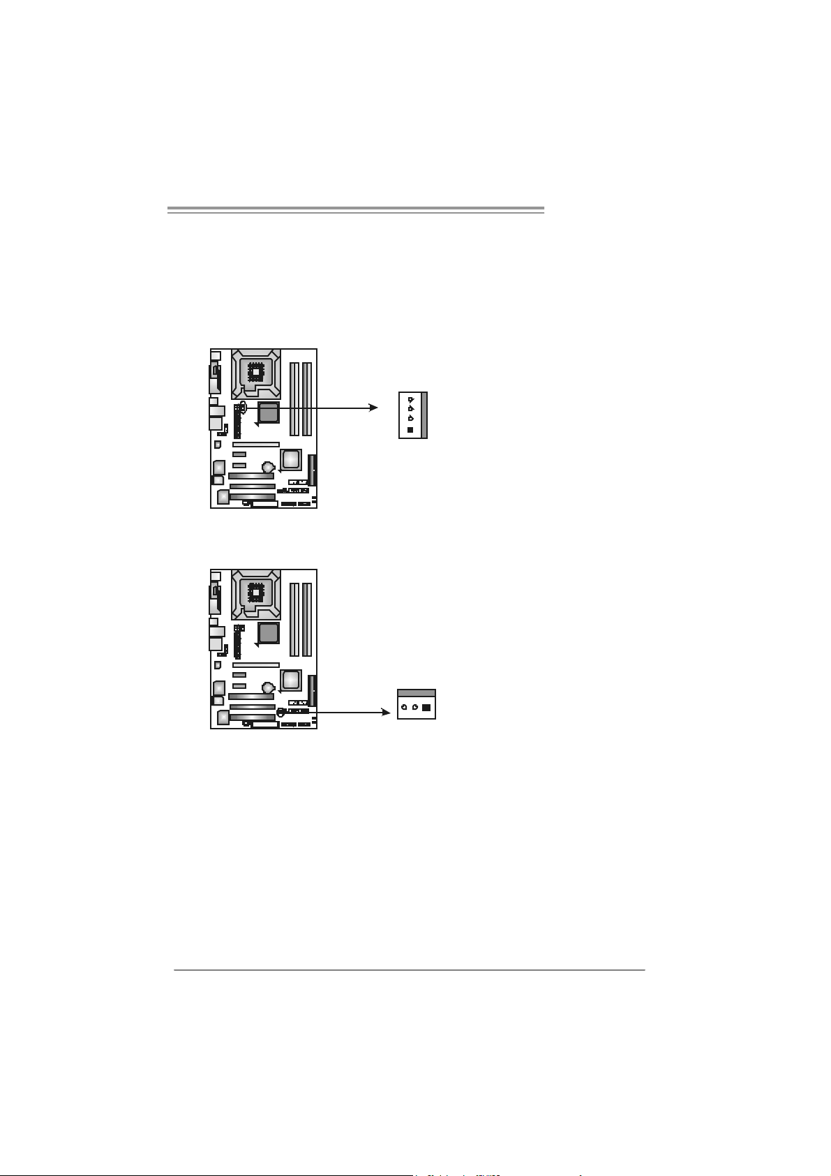
2.2 FAN HEADERS
These fan headers support cooling-fans built in the computer. The fan
cable and connector may be different according to the fan manufacturer.
Connect the fan cable to the connector while matching the black wire to
pin#1.
JCFAN1: CPU Fan Heade r
JCFAN1
4
1
JSFAN1: S ystem Fan Header
JSFAN1
31
Assignment
Pin
1 Ground
2 +12V
3 FAN RPM rate
sense
4 Smart Fan
Control
Pin
Assignment
1 Ground
2 +12V
3 FAN RPM rate
sense
Note:
The J C FAN1 a nd JSFAN1 s up por t 4-pi n and 3- pi n head connec tor. W he n c o nn ecti ng
with wi r es ont o conn ect or s, ple ase no te tha t t he r e d wire is t he posi ti ve an d s houl d be
conn ecte d t o pi n# 2, and th e bl ac k wire is Gro und and s hould b e c onnect ed to GN D .
9
Page 12
Motherboard Manual
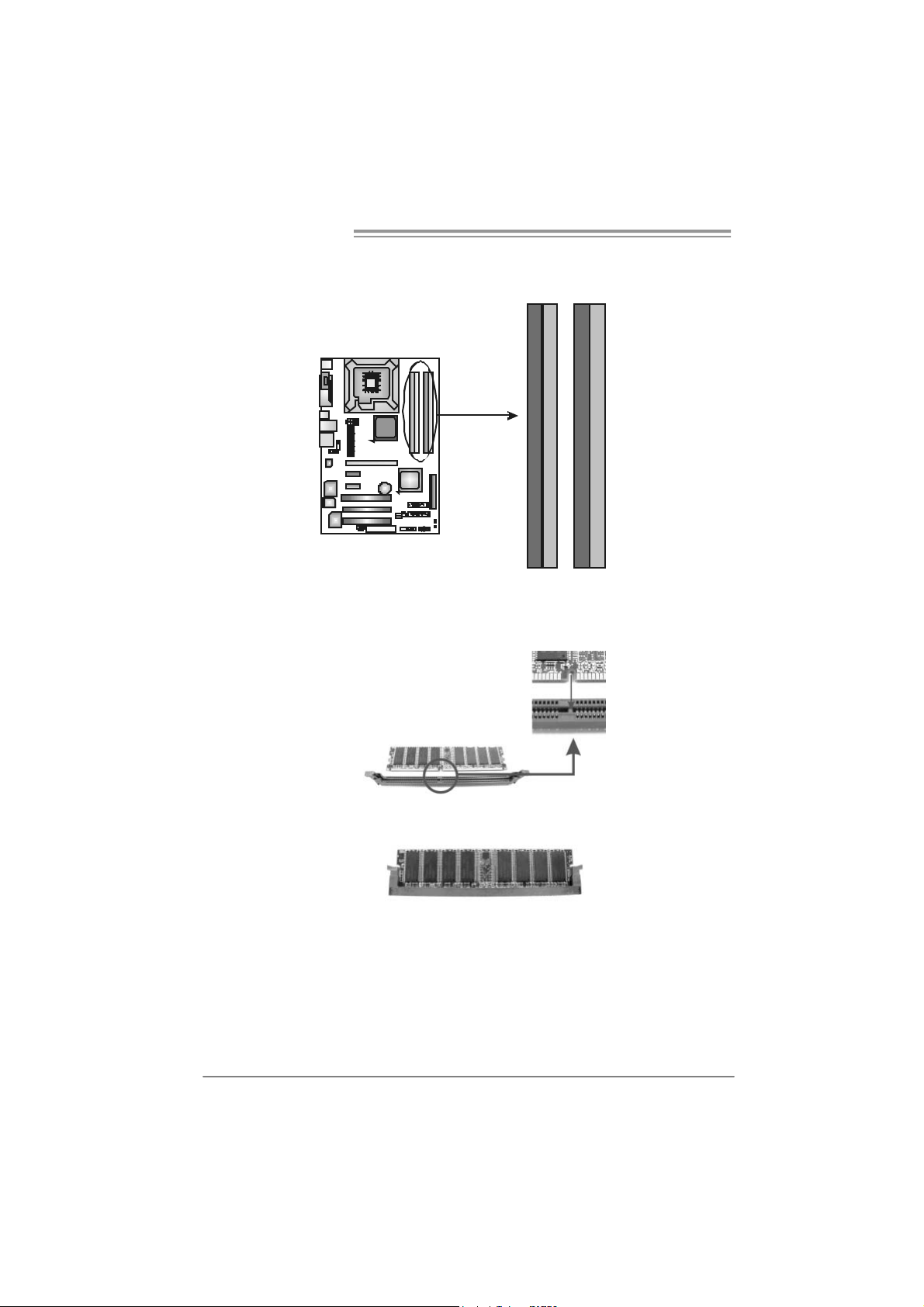
2.3 INST ALLING SYST EM MEMORY
A. Memory Modules
DDR2_A1
DDR2_A2
DDR2_B1
DDR2_A1
DDR2_A2
1. Unlock a DIMM slot by pressing the retaining clips outward. Align a
DIMM on the slot such that the notch on the DIMM matches the
break on the Slot.
DDR2_B2
DDR2_B1
DDR2_B2
2. Insert the DIMM vertically and firmly into the slot until the retaining
chip snap back in place and the DIMM is properly seated.
10
Page 13

T Force 94 5P SE
B. Mem ory Capa city
DIMM Socket
Location
DDR2_A1 256MB/512MB/1GB *1
DDR2_A2 256MB/512MB/1GB *1
DDR2_B1 256MB/512MB/1GB *1
DDR2_B2 256MB/512MB/1GB *1
DDR Module Total Memory Size
Max memory 4GB.
C. Dual Ch ann el Mem ory in stalla t i on
To t rigger the D ual Channel f unc tion of the motherboard, the memory module
must meet the f ollowing requirements:
Install memory module of the same density in pairs, shown in the f ollowing table.
Dual Channel Status
Enabled O X O X
Enabled X O X O
Enabled O O O O
(O means memory installed, X means memory not installed.)
The DRAM bus width of the memory module must be the same (x8 or
x16)
DDR2_A1
DDR2_A2 DDR2_B1 DDR2_B2
11
Page 14
Motherboard Manual
2.4 CONNECT ORS AND SLOTS
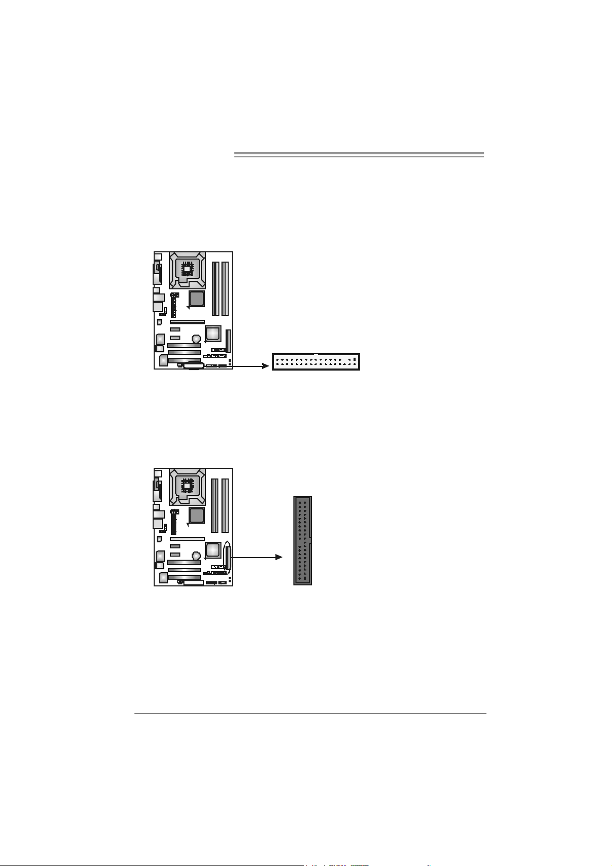
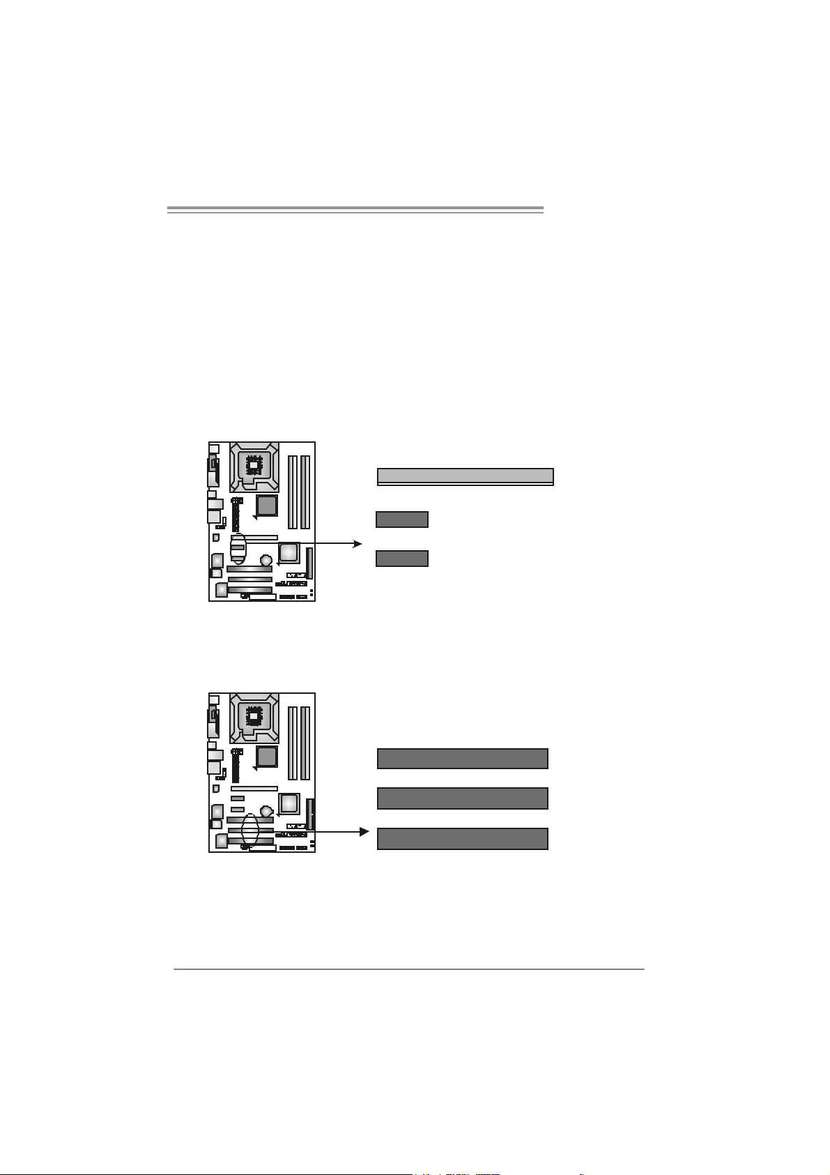
FDD1: Floppy Disk C onnector
The motherboard prov ides a standard floppy disk connector that supports 360K,
720K, 1.2M, 1.44M and 2.88M floppy disk ty pes . This connec tor s upports the
prov ided floppy drive ribbon cables.
33
1
234
ID E1: Hard Disk Conne ctors
The motherboard has a 32-bit Enhanced PCI I DE Controller that prov ides PI O
Mode 0~4, Bus Master, and Ultra DMA 33/ 66/100 functionality.
The IDE connectors can connect a master and a slav e drive, so you can connect
up to two hard dis k driv es. The first hard driv e s hould alway s be connected to
IDE1.
IDE1
40
39
21
12
Page 15
T Force 94 5P SE
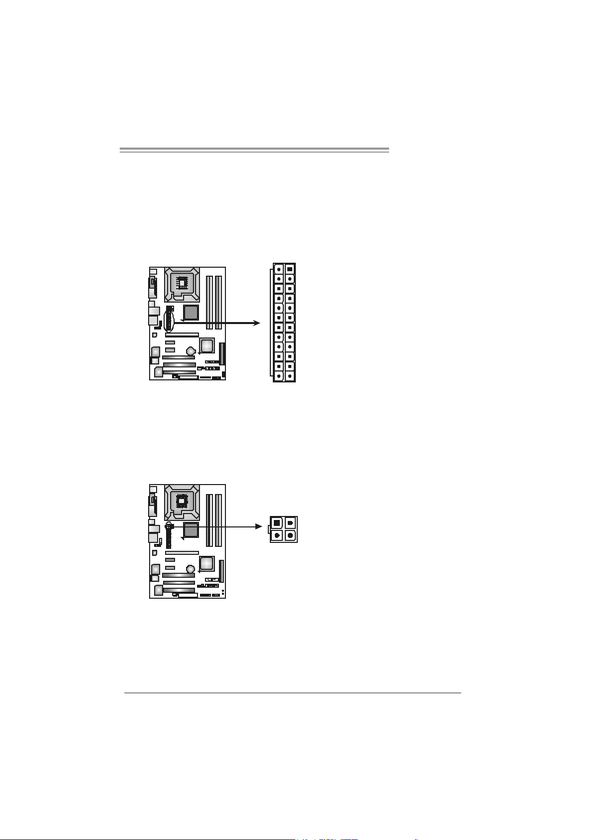
PEX16_1: PCI-Express x16 Slot
- PCI-Express 1.0a compliant.
- Maximum theoretical realized bandwidth of 4GB/s sim ultaneous ly per
direction, f or an aggregate of 8GB/s totally.
PEX1_1/PEX1_2: PCI-Express x1 Slots
- PCI-Express 1.0a compliant.
- Data transf er bandwidth up to 250MB/s per direct ion; 500MB/s in total.
- PCI-Express supports a raw bit-rate of 2. 5Gb/s on the data pins.
- 2X bandwidth over t he traditional PCI arc hitecture.
PEX16_1
PEX1_1
PEX1_2
PCI1~PCI3: Peripheral Component Interconnect Slots
This motherboard is equipped with 3 st andard PCI slots. PCI stands f or
Peripheral Component Interconnect, and it is a bus standard for expansion
cards. This PCI s lot is designated as 32 bits.
PCI1
PCI2
PC I3
13
Page 16

Motherboard Manual
_
CHAPTER 3: HEADERS & JUM PERS SETUP
3.1 H
OW T O SET U P JUMPERS
The illustration shows how to set up jumpers. When the jumper cap is
placed on pins, the jumper is “close”, if not, that means the jumper is
“open”.
Pin opened Pin closed Pin1-2 closed
3.2 DET AIL SET T I N GS
JPANEL1: Front Panel Header
This 16-pin connector includes Power-on, R eset, HDD LED , Power LED, Sleep
button, and speak er connec tion. It allows user t o connect the PC c ase’s front
panel switch functions.
LED
PW R
SLP
916
1
SP K
++
HLED
+
On/Off
-
-
RST
8
14
Pi n As signment Functio n Pin Assignment Functio n
1 +5V 9 Sl eep control
2 N/A 10 Ground
3 N/A 11 N/A N/A
4 Speaker
5 HDD LED (+) 13 Power LED (+)
6 HDD LED (-)
7 Ground 15 Power button
8 Reset control
Speaker
connector
Hard drive LED
Reset button
12 Po we r LE D (+)
14 Po we r LE D (-)
16 Ground
Sleep button
Power LED
Power-on button
Page 17
T Force 94 5P SE
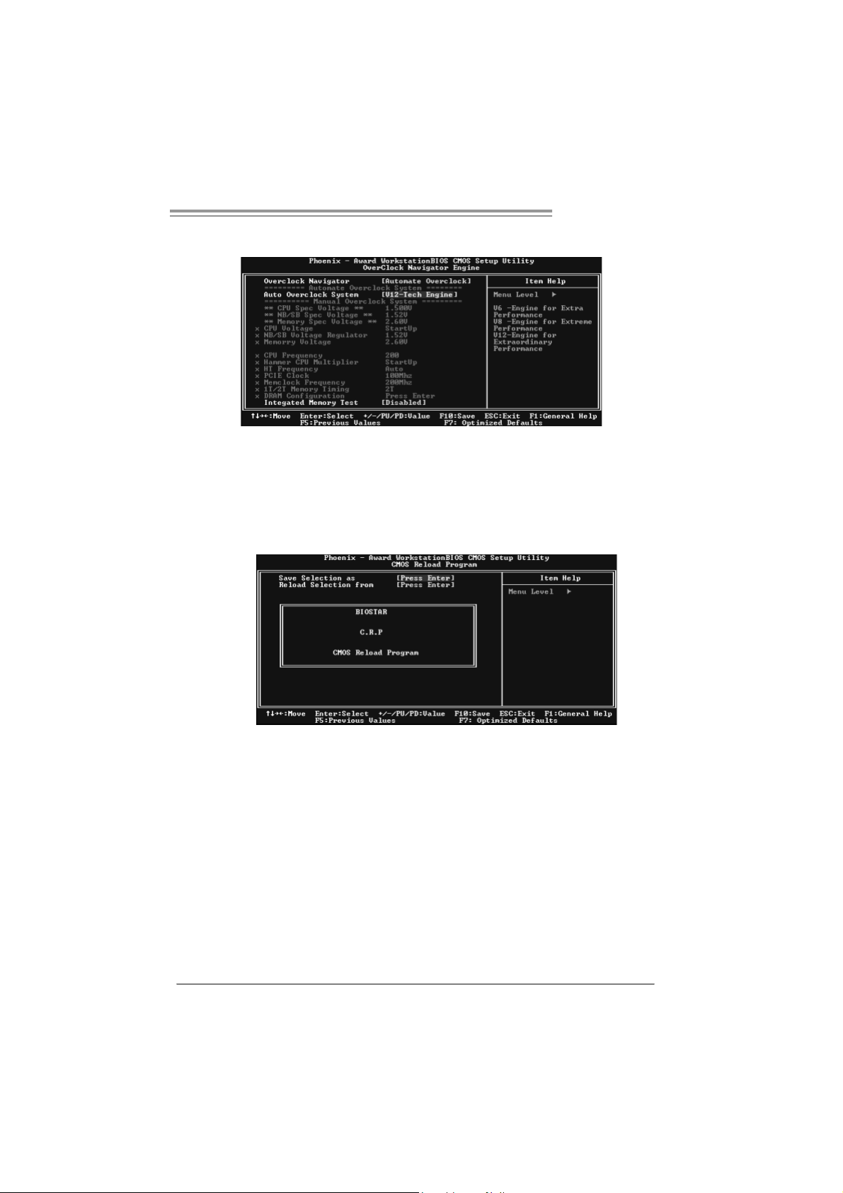
J A TXPW R1 : A TX Po we r S ou rce C onne ct o r
This connector allows user to c onnect 24-pin power connector on the ATX
power supply.
Pi n As signment
1 +3.3V
2 +3.3V
3 Ground
4 +5V
13
24 12
1
5 Ground
6 +5V
7 Ground
8 PW_OK
9 Standby Voltage
+5V
10 +12V
11 +12V
12 2 x 12 Detect
13 +3.3V
14 -12V
15 Ground
16 PS_ON
17 Ground
18 Ground
19 Ground
20 -5V
21 +5V
22 +5V
23 +5V
24 Ground
J A TXPW R2 : A TX Po we r S ou rce C onne ct o r
By connecting this connector, it will prov ide +12V t o CPU power c ircuit .
Pin
Assignment
1 +12V
3412
2 +12V
3 Ground
4 Ground
15
Page 18

Motherboard Manual
JUSB3/JUSB4: Heade rs for USB 2.0 Ports at Front Panel
This motherboard prov ides 2 USB 2.0 headers, which allows user to connect
additional USB cable on t he PC front panel, and also can be connected with
internal USB dev ices, like U SB card reader.
JUSB3 JUSB4
210
1
9
JAUDIO F1: Fron t Panel Audio Heade r
This header allows user t o connect the front audio output cable with t he PC front
panel. It will disable t he output on back panel audio c onnectors.
1
9210
Assignment
Pin
1 +5V (fused)
2 +5V (fused)
3 USB4 USB5 USB+
6 USB+
7 Ground
8 Ground
9 Key
10 NC
Pi n As signment
1 Mic Left in
2 Ground
3 Mic Right in
4 GPIO
5 Right line in
6 Jack Sense
7 Front Sense
8 Key
9 Left line in
10 Jack Sens e
JCDIN1: CD-ROM Audio-in Connector
This connector allows us er to connect t he audio source from the v ariaty dev ices,
like CD-ROM, DVD-ROM, PC I sound card, PCI TV turner card etc..
16
Assignment
Pin
14
1 Left Channel
Input
2 Ground
3 Ground
4 Right Channel
Input
Page 19

T Force 94 5P SE
JCMOS1: Clear CMOS Header
By placing the jumper on pin2-3, it allows us er to restore the BIOS saf e set ting
and the CMOS dat a, please carefully f ollow the procedures to avoid damaging
the motherboard.
13
Pin 1-2 Close:
Normal Operation (Default).
13
Pin 2-3 Close:
Clear CMOS data.
13
※ Clear CMOS Proce dures:
1. Remov e AC power line.
2. Set the jumper to “Pin 2-3 close”.
3. Wait f or f ive seconds.
4. Set the jumper to “Pin 1-2 close”.
5. Power on the AC.
6. Reset your desired password or clear the CMOS data.
JC I1: Chas sis O pen Heade r (Optio nal )
This connector allows system to m onitor PC c ase open status. If the signal has
been triggered, it will record t o the CMOS and show the message on next
boot-up.
Pin
Assignment
1 Case open signal
2 Ground
12
17
Page 20

Motherboard Manual
SATA1~SATA4: Se rial ATA Connectors
The motherboard has a PCI t o SATA Controller wit h 4channels SATA interf ace, it
satisfies the SATA 2.0 spec and with transfer rate of 3Gb/s.
SATA1 SATA 3
SATA2
JSP DIF_O UT: Di git al Audio out C onne ctors
This connector allows user to connect the PCI bracket SPDIF output
header.
174
SATA4
Pin
Assignment
1 Ground
2 TX +
3 TX 4 Ground
5 RX6 RX+
7 Ground
Pin
Assignment
1 +5V
2 SPDIF_OUT
3 Ground
On-Board Buttons
There are 2 on-board buttons.
PWRSW1:
This is an on-board Power Switch button.
RSTSW1:
This is an on-board Reset button.
18
31
PW RS W1
RSTSW1
Page 21

CHAPTER 4: OVERCLOCK QUICK GUIDE
4.1 T-POW ER INT RODUCT ION
Biostar T-Power is a whole new utility that is designed for overclock users.
Based on many precise tests, Biostar Engineering Team (BET ) h a s
developed this ultimate overclock engine to raise system performance.
No matter whether under BIOS or Windows interface, T-Power is able to
present the best system state according to users’ overclock setting.
T- P o w e r B IO S Fe at ure s :
Ov erc locking Nav igator Engine (O.N.E.)
CMOS Reloading Program (C.R.P.)
Memory Integration Test (M.I.T., under Ov erclock Nav igator Engine)
Integrated Flash Program (I.F.P. )
Smart Fan Function (under PC Health Stat us)
Self Recov ery System (S.R.S)
T-Power Windows Feature:
Hardware Monitor
Ov erclock Engine
Smart Fan Function
Lif e Update
T Force 94 5P SE
19
Page 22

Motherboard Manual
4.2 T-POWER BIOS FEAT URE
A. Overclocking Navigator Engine (O.N.E.):
ONE provides two powerful overclocking engines: MOS and AOS for both
Elite and Casual overclockers.
Ma nu al O ve rcl ock Sys tem (M.O .S .)
MOS is designed f or experienc ed overclock users.
It allows users to c ustomize personal overclock set tings .
20
Page 23

T Force 94 5P SE
CPU Ov erclock Setting:
CPU Voltage:
This f unction will increase CPU stability when overc locking. Howev er, the
CPU temperature will increase when CPU volt age is increased.
Choices: The range is from 1.2V t o 1.725V, with an int erval of 0.0.25V.
CPU Frequency:
CPU Frequency is directly in proport ion to system perf ormance. To
maintain the system st ability, CPU v olt age needs to be increased also
when raising CPU frequency.
Choices: This range is f rom 200 to 450, with an interval of 1MHz.
Memory Overclock Setting:
Memo ry Voltage:
This f unction will increase memory stability when ov erclocking.
Choices: The range is from 1.85V t o 2.0V, with an int erval of 0.05V.
Memclock Fr eq uency:
To get better syst em performance, sometimes downgrading the memory
frequency is necessary when C PU f requency is adjust ed over the upper
limit.
Choices: D DR2 400, DDR2 533, DDR2 667, DDR2 800 (MHz).
PCI-Express Overclock Setting:
PCI-E Clock:
It helps to increase VGA card performance.
Choices: The range is from 100 to 145, with an interv al of 1MHz.
Chipset Overclock Setting:
NB/SB Voltage Regulator:
This f unction will increase chipset stability when ov erclocking.
Choices: 1.52V, 1. 60V, 1.68V, 1.76V.
HT Frequency:
We recommend users to s et this item at “x4” when overclocking.
Choices: x1, x2, x3, x4, x5, Auto.
21
Page 24

Motherboard Manual
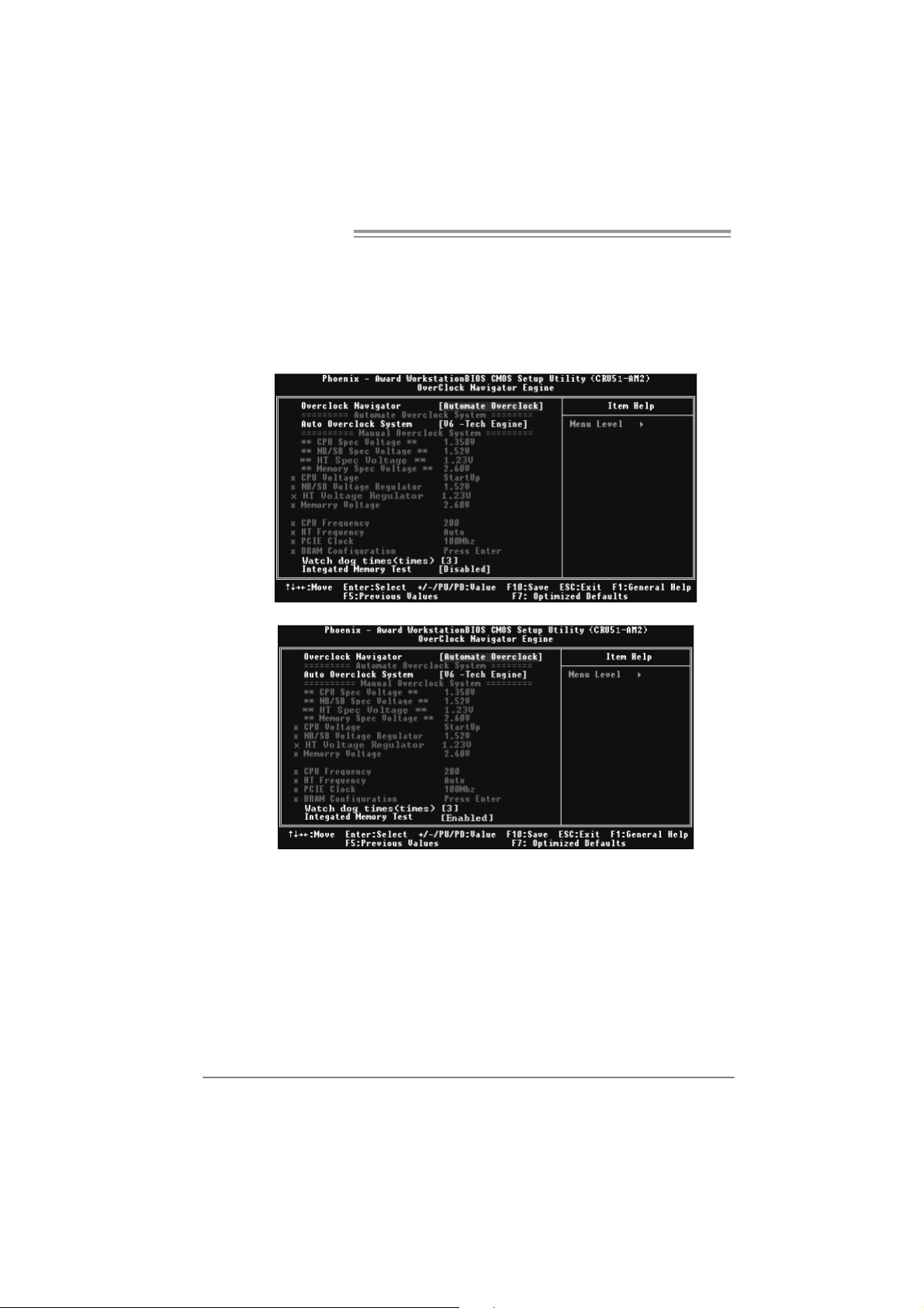
Au tom atic O ve rclo ck S ys tem (A.O .S .)
For beginners in overclock f ield, BET had developed an easy, fast, and
powerful feature to increase t he syst em performance, named A.O.S.
Based on many tests and experiments, A. O.S. prov ides 3 ideal overclock
configurations that are able to rais e the system perf ormance in a single
step.
V6 Tech En gine:
This setting will raise about 10%~15% of whole system perf ormance.
22
V8 Tech En gine:
This setting will raise about 15%~25% of whole system perf ormance.
Page 25
T Force 94 5P SE
V12 Tech Engine:
This setting will raise about 25%~30% of whole system perf ormance.
B. CMOS Reloading Program (C.R.P.):
It allows users to save different CMOS settings into BIOS-ROM.
Users are able to reload any sav ed CMOS setting for customizing system
configurations.
Moreover, users are able t o save an ideal overclock setting during overclock
operation.
There are 50 sets of record addresses in total, and us ers are able to name the
CMOS data according t o personal preference.
23
Page 26
Motherboard Manual
C. Memory Integration Test (M.I.T.):
This f unction is under “Overclocking Nav igator Engine” item .
MIT allows users t o test memory c ompatibilities, and no extra devices or
software are needed.
Step 1:
The def ault setting under this it em is “Disabled”; the condition param eter should
be changed to “Enable” to proc eed this test.
↓
24
Step 2:
Sav e and Exit f rom C MOS setup and reboot the system to activate this test.
Run this test for 5 minutes (minimum) to ensure the memory stability.
Step 3:
When the process is done, change the set ting back from “Enable” to “Disable”
to complete the test.
Page 27
T Force 94 5P SE
D. Self Recovery System (S.R.S.):
This f unction can’t be s een under T-Power BIOS setup; and is always on
whenever the syst em starts up.
Howev er, it can prevent syst em hang-up due to inappropriate overclock
actions.
When the system hangs up, S.R.S. will aut omat ically log in the def ault BIOS
setting, and all overclock set tings will be re-configured.
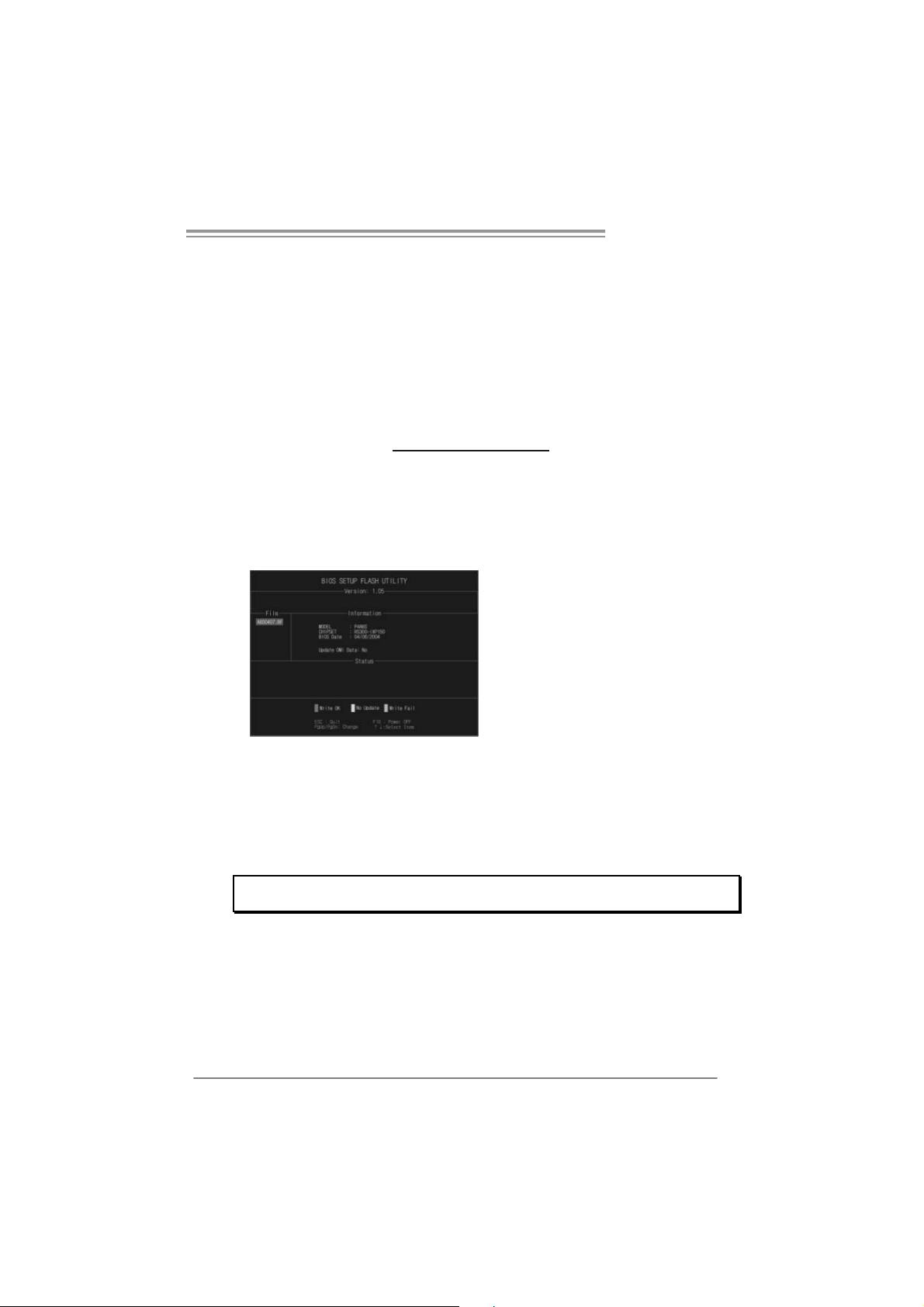
E. Integr ated Flash Progr am (I.F.P.):
IFP is a s afe and quick way to upgrade BIOS.
Step 1:
Go to Biostar website (ht t p: //www. bios t ar.c om. t w) t o download the latest BIOS
f ile. Then, sav e the f ile into a floppy disk.
Step 2:
Insert the f loppy disk and reboot the sys tem to get into CMOS screen.
Step 3:
Select the item “Integrated Flas h Program” to get the following f rame and
choose the BIOS file downloaded in step 1.
Step 4:
Press “Enter” key to start BIOS file loading, and BIOS updating will process
automatically.
Step 5:
When the BIOS update is completed, press Y ES to the mes sage “F lash done,
Reset system”, and the system will reboot autom atic ally to f inish t he process.
Advis e:
You can update the system BIOS by simply pr essing “Enter ” key for three times.
25
Page 28

Motherboard Manual
F. Smar t Fan Function:
Smart Fan Function is under “PC Health St atus”.
This is a brilliant feat ure to control CPU Tem perature vs. Fan speed.
When enabling Smart Fan func tion, Fan speed is controlled automatically by
CPU temperature.
This f unction will protect CPU f rom overheat problem and maint ain the system
temperature at a saf e level.
↓
26
CPU Fa n Off <℃>:
If the CPU temperature is lower than the set value, the CPU fan will t urn
off. The range is f rom 0℃ ~127℃, with an interval of 1℃.
CPU Fa n Start <℃>
The CPU fan starts to work when CPU temperature arrives to this set
v alue. The range is from 0℃ ~127℃, with an interv al of 1℃ .
CPU Fan Full speed <℃>
When CPU temperature arrives to t he set value, the CPU fan will work
under Full Speed. The range is f rom 0℃ ~127℃ , with an interval of 1℃.
Page 29
T Force 94 5P SE
Start PWM Value
When CPU temperature arrives to t he set value, the CPU fan will work
under Smart Fan Function mode. The range is from 0~127, with an
interv al of 1.
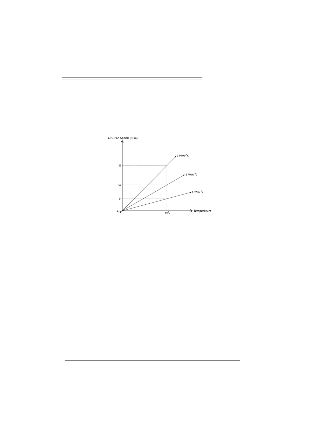
Slope PWM
Choices: 1 PWM Value/℃ ( d ef a u l t ), 2 P W M Va l ue/℃ , 4 PWM Value/℃, 8
PWM Value/℃, 16 PWM Value/℃ , 32 PWM Value/℃, 64PWM Value/℃ .
S1: CPU temperature is 60℃, and PWM v alue is 1 PWM/℃.
S2: CPU temperature is 60℃, and PWM v alue is 2 PWM/℃.
S3: CPU temperature is 60℃, and PWM v alue is 3 PWM/℃.
Increasing the v alue of slope PW M will raise the speed of CPU f an.
As in above diagram, when t he CPU temperature reaches 60℃, the CPU
f an speed f or 3 PWM/℃ is higher than 1 PWM/℃ (S1<S2<S3).
27
Page 30

Motherboard Manual
4.3 T-POWER WINDOWS FEATURE
A.Hardware Monitor:
T-Power Ha rd ware mo ni tor all o ws users to m o ni tor system vo ltage ,
temperature and fan speed accordingly.
Additionally, a rescue action will be taken by the program automatically
while the system faces an abnormal condition. The program will trigger an
alarm or shut down the system when unpredictable errors occur.
All the monitoring items are illustrated by a waveform diagram.
Hardware Moni tor Toolbar
28
i. Start-up Setting
Click on this item t o run Hardware Monitor Program when the Windows
starts-up.
ii. Dialogue-Box Setting
Click on this item t o pop-up warning dialogue-box when PC system is
abnormal.
iii. Exit
Click on this item to exit Hardware Monitor Program.
iv. Hide
Click on this item t o hide this program in system tray. When hiding the
program, there will be a check icon in t he system tray.
Page 31

T Force 94 5P SE
CPU Temperature
This column configures the CPU temperature. There is a wav ef orm to
represent the status of CPU temperature.
By adjusting , users can easily configure the upper limit of CPU
temperature for system operating.
In this diagram, t he white line represents the upper lim it which user-s et f or CPU
temperature and the green line shows present CPU temperature.
If the CPU temperature is higher than t he upper limit, the status line color will
change from green to red, and a warning sound will alert y ou. Also, the system
tray icon
would change to .
FAN S pee d
By adjusting , users can easily configure the lower limit of t he f an speed.
In this diagram, the green line shows present CPU Fan speed, and the y ellow
line shows System Fan speed (if any ).
If any one of the f ans speeds is lower than the set value, the status line will
change into a red warning line, and the program will trigger an alarm system
automatically. Also, the sys tem tray icon
would change to .
29
Page 32

Motherboard Manual
C PU/Batte ry Voltage
i. VCore
This item displays the CPU voltage, represented by a light blue line.
Users can set the upper and lower lim it by adjusting
CPU operating voltage.
If CPU v oltage is higher or lower than the set value, the status line will
change into a red warning line, and a warning sound will alert y ou. Also,
the system tray icon
ii. VBAT
This item display s t he CMOS battery voltage, represented by a light green
line.
Users can set the upper and lower lim it by adjusting
status of battery voltage.
If battery voltage is higher or lower than the set v alue, the status line will
change to a red warning line, and a warning sound will alert y ou. Also, the
system tray icon
will change to .
will change to .
to monitor the
to monitor the
Reference data
This column represents t he status of power supply voltage and cannot be
adjusted, it is only for pres ent status referenc e.
30
Page 33

B. Over clocking Co nfigur ati ons
This diagram is designed f or T-series
Ov erclock ing utility. F riendly interface and solid
ov erclock features are the major concept of this
utility.
Graphic 1 will appear when activ ating this utility.
A. Clicking on “Biostar” will lead y ou to the
Biostar Homepage.
B. This column shows the CPU speed
inf ormation.
C. Click on this button and t he utility will
pop-up 4 sub-screens (Please ref ers to
Graphic 3).
D. Click on this button to minimize this
program to taskbar.
E. This column shows present CPU speed
and ov erclock ing percentage.
F. Clicking on this button will mak e the
Graphic 2
program start up as soon as the
Windows starts up.
G. Click on this button to exit this overclock
utility.
H. Click on this button to reset all t he
ov erc lock features to default setting.
T Force 94 5P SE
Graphic 1
By adjusting the overclocking
f eatures in 4 s ub-screens, users can
tune the system perf ormance to an
optimal level.
Graphic 3
31
Page 34

Motherboard Manual
CPU Overclocking Settings:
Memory Overclocking Settings:
By adjusting can configure three items
for CPU overclocking.
A. CPU Frequency
Rang e: 2 00MHz~ 450M H z.
Inter val: 1MHz.
B. CPU Ratio
Rang e: 4~ 25.
Inter val: 1.
C. CPU Voltage
Rang e: 0 .8V~ 2.0V.
Inter val: 0.01 25 V.
By adjusting can configure two items for
Memory overclocking.
A. Memory Clock Frequency
Choic es: 10 0, 1 33, 20 0, 266 , 3 33, 40 0, 5 33 ,
667 , 8 00.
B. Memory Voltage
Rang e: 1 .8V~ 2.8V.
Inter val: 0.1V.
32
AGP/PCI-Express Overclocking Setting: (Optional)
By adjusting can configure VGA card
overclocking. And this function helps to
increase VG A card perfo rmance.
Rang e: 1 00MHz~ 150M H z.
Inter val: 1MHz.
Page 35

T Force 94 5P SE
PCI Overclocking Setting:
This diagram shows present PCI working
status and helps to monitor PCI peripherals
working status.
This item cannot be adjusted.
33
Page 36

Motherboard Manual
C. S mar t Fan Functio n
When Smart Fan Function is activated, screens will pop-up to illustrate
the fan speed information.
i. CPU Temperature:
Show current CPU temperature.
ii. CPU Fan speed:
Show current CPU Fan speed.
iii. System Fan speed:
Show current system Fan speed.
iv. Calibrate:
When changing CPU Fan or System Fan, click on this button to
re-calibrate the Fan speed.
34
Note:
1. Whe n S mar t F an Func tion ac ti vates for t he fi r st ti m e, t hi s cali br ate f uncti on w oul d
aut o- r un to g et up per a nd l o wer l i mita tion of C PU F an and S ys te m Fa n.
2. When c alibrating proc ess is done, the calibrating window will auto-close, and the
main screen will show new f an s peed dat a.
Page 37

T Force 94 5P SE
v. Auto:
If the green indicator is lit up, the Smar t Fan Function is “On”
(Default Setting).
Click on this button again to c lose Smart Fan Function, and a
scr een as below would pop-up.
There will be pulling-meter besides the CPU Fan and System Fan,
the CPU Fa n a nd the System Fa n speed can b e ad justed b y
adjusting the Cur sor Up or Down.
vi. Program Tool Bar:
z About:
Click on this button to g et progr am-r elated information.
z Minimize:
Click on this button to mi nimize the pr ogram to system tray
z Exit:
Click on this button to exit this progr am.
35
Page 38

Motherboard Manual
D. Live Update
When Live Update program is activated, a screen will pop up to illustrate
BIOS related i nformation.
i. Link to Internet:
Click on this button wi ll link to Biostar website and BIOS file will
be downloaded.
ii. Update BIOS:
Click o n this b utto n to r un BIOS flashi ng pr ocess, and it’s easy
and safe.
iii. Backup BIOS:
Click on this button, and BIOS file wi ll be saved into the
user - select ed f older.
iv. Clear CMOS:
Click on this item will clear the CM OS Data. When car rying this
job, the previous CMOS data would be cleared and r eturned to
default s etting.
36
Page 39

CHAPTER 5: USEFUL HELP
5.1 DRIVER INST ALLATION NOT E
After you installed your operating system, please insert the Fully Setup
Driver CD into your optical drive and install the driver for better system
performance.
You will see the following window after you insert the CD
T Force 94 5P SE
The se tup guide will auto dete ct your m otherboard and operating system .
Note:
If this wi n dow di dn’ t sho w up aft er yo u ins ert th e D r i ver CD, ple as e us e file br ows er to
locate an d e xecu te th e file SETU P.E XE un der your optical dr i ve .
A. Driver Installation
To install the driver, please click on the Driver icon. The setup guide will
list the compatible driver for your motherboard and operating system.
Click on each device driver to launch the installation program.
B. Softwar e Installation
To install the software, please click on the Software icon. The setup guide
will list the software available for your system, click on each software title
to launch the installation program.
C. M anual
Aside from the paperback manual, we also provide manual in the Driver
CD. Click on the Manual icon to browse for available manual.
Note:
You will need Acrobat Reader to open the manual file. Please download the latest version
of Acrob at Re ad er soft ware fro m
http://www.adobe.com/products/acrobat/readstep2.html
37
Page 40

Motherboard Manual
5.2 AWARD BIOS BEEP CODE
Beep Sound Meaning
One long beep followed by t wo short
beeps
High-low siren sound CPU overheated
One Short beep when system boot-up No error found during POST
Long beeps every other sec ond No DRAM detec ted or install
Video card not found or v ideo card
memory bad
System will shut down autom atic ally
5.3 EXT R A INFORMAT ION
A. BIOS Update
After you fail to update BIOS or BIOS is invaded by virus, the
Boot-Block function will help to restore BIOS. If the following message
is shown after boot-up the system, it means the BIOS contents are
corrupted.
In this Case, please follow the procedure below to restore the BIOS:
1. Make a bootable floppy disk.
2. Download the Flash Utility “AWDFLASH.exe” from the Biostar
website: www.biostar.com.tw
3. Confirm motherboard model and download the respectively BIOS
from Biostar website.
4. Copy “AWDFLASH.exe” and respectively BIOS into floppy disk.
5. Insert the bootable disk into floppy drive and press Enter.
6. System will boot-up to DOS p rompt.
7. Type “Aw dflash xxxx.bf/sn/py/r” in DOS prompt.
(xxxx means BIOS name.)
8. System will update BIOS automatically and restart.
9. T he BIOS has b een recovered a n d will work properl y.
38
Page 41

T Force 94 5P SE
B. CPU Overheated
If the system shutdown automatically after power on system for
seconds, that means the CPU protection function has been activated.
When the CPU is over heated, the motherboard will shutdown
automatically to avoid a damage of the CPU, and the system may not
power on again.
In this case, please double check:
1. The CPU cooler surface is placed evenly with the CPU surface.
2. CPU fan is rotated normally.
3. CPU fan speed is fulfilling with the CPU speed.
After confirmed, please follow steps below to relief the CPU protection
function.
1. Remove the power cord from power supply for seconds.
2 . Wa i t f o r se c o nd s.
3. Plug in the power cord and boot up the system.
Or you can:
1. Clear the CMOS data.
(See “Close CMOS Header: JCMOS1” section)
2 . Wa i t f o r se c o nd s.
3. Po wer on the syste m ag ai n.
39
Page 42

Motherboard Manual
e
5.4 TROUBLESHOOTING
Probable Solution
1. No power to the system at all
Power light don’t illuminate, f an
inside power supply does not turn
on.
2. Indicat or light on keyboard does
not turn on.
System inoperative. Keyboard lights
are on, power indicator lights are lit,
and hard driv e is spinning.
System does not boot f rom hard disk
driv e, can be booted from optical driv e.
System only boots f rom opt ical driv e.
Hard disk can be read and applications
can be used but boot ing from hard dis k
is impossible.
Screen message says “Invalid
Configuration” or “CMOS Failure.”
Cannot boot system after installing
second hard driv e.
1. Make sure power cable is
securely plugged in.
2. Replace cable.
3. Cont act technical support.
Using even pressure on bot h ends of
the DIMM, press down f irmly until the
module snaps into place.
1. Check cable running from disk to
disk controller board. Make s ure
both ends are securely plugged
in ; c h ec k t h e d r iv e ty pe i n t h e
standard CMOS s etup.
2. Backing up the hard drive is
extremely important. All hard
disks are capable of break ing
down at any time.
1. Back up data and applications
files.
2. Ref orm at the hard drive.
Re-install applications and data
using backup disks.
Review system’s equipment. Mak e sur
correct inf ormation is in s etup.
1. Set master/slave jumpers
correctly.
2. Run SETUP program and select
correct driv e types. Call the drive
manufacturers f or c ompatibility
with other drives.
40
Page 43

T Force 94 5P SE
This page is intentionally left blank.
41
Page 44

Motherboard Manual
AP PEND ENCIES: SPEC IN OTHER LANGUAGE
GERMAN
Ve r 6. x Ve r 5. x
LGA 77 5
Intel Core2Duo / Pentium 4 / Pentium D /
Celeron D Prozessoren mit bis zu 3,8 GHz
CPU
FS B 533 / 800 / 106 6 MHz 533 / 800 / 106 6 MHz
Chipsatz
Super E/A
Arbeitsspeic
her
IDE
SATA
LAN
Audio-Code
c
Unterstützt Hyper-Threading
Execute Dis able Bit
Enha nced Intel Sp eedStep®
Extende d Memor y 64 Tech nolog y
Int el 9 45P
Intel ICH7
ITE 871 8F
Hardware-Überwachung
Lüfterdrehzahl-Controller
"Smart Guardian" -Fun ktion v on ITE
DDR2 DIMM-S tec kplätz e x 4
Jeder DIMM u nterstützt 128/256/51 2MB &
1GB DDR2
Max. 4GB Arbeitsspeicher
Dual-Kanal D DR Speic h ermodul
Unterstützt DDR2 533 / 667
Integrierter IDE-Controller
Ultra DMA 33 / 66 / 100 B us M as ter-Modus
Unterstützt PIO-Modus 0~4
Integrierter Serial ATA-Controller
Datent rans ferr ate bi s z u 3.0 Gb/s
Konform mit der SATA-Spezifikation
Version 2.0
Realtek 81 10S C
10 / 1 00 Mb /s un d 1 Gb/s A ut o-Ne goti at i on
Halb-/ Vollduplex-Funktion
AL C 861V D
5.1-K anal-Au dioausg abe
Unterstützt Intel High-Definition Audi o
42
LGA 77 5
Intel Core2Duo / Pentium 4 / Pentium D /
Celeron D Prozessoren mit bis zu 3,8 GHz
Unterstützt Hyper-Threading
Execute Dis able Bit
Enha nced Intel Sp eedStep®
Extende d Memor y 64 Tech nolog y
Int el 9 45P
Intel ICH7
ITE 871 8F
Hardware-Überwachung
Lüfterdrehzahl-Controller
"Smart Guardian" -Fun ktion v on ITE
DDR2 DIMM-S tec kplätz e x 4
Jeder DIMM u nterstützt 128/256/51 2MB &
1GB DDR2
Max. 4GB Arbeitsspeicher
Dual-Kanal D DR Speic h ermodul
Unterstützt DDR2 533 / 667
Integrierter IDE-Controller
Ultra DMA 33 / 66 / 100 B us M as ter-Modus
Unterstützt PIO-Modus 0~4
Integrierter Serial ATA-Controller
Datent rans ferr ate bi s z u 3.0 Gb/s
Konform mit der SATA-Spezifikation
Version 2.0
Realtek 81 10S C
10 / 1 00 M b/s un d 1Gb/s Auto-Ne gotiation
Halb-/ Vollduplex-Funktion
AL C 888
7.1-K anal-Au dioausg abe
Unterstützt Intel High-Definition Audi o
Page 45

Ve r 6. x Ve r 5. x
PCI Expr ess x16 Steckplatz x1 PCI Express x16 S teckplatz x1
Steckplätze
Onboard-An
schluss
Rückseiten-
E/A
Platinengr ö
ße.
OS-Unterst
ützung
PCI Expr ess x1 Steckplatz x2 PCI Express x1 Steckplatz x2
PCI-Steckplatz x3 PCI-Steckplatz x3
Diskettenlaufwerkanschluss x1 Diskettenlaufwerk anschluss x1
IDE-Anschluss x1 IDE-Anschluss x1
SATA-Anschluss x4 SATA-Anschluss x4
Fronttafelanschluss x1 Fronttafelanschluss x1
Front-Audioanschluss x1 Front-Audioanschluss x1
CD-IN-Anschluss x1 CD-IN-Anschluss x1
S/PDIF Eingangsanschluss x1 S/PDIF Ei ngangsanschluss x1
CPU-Lüfter-Sockel x1 CPU-Lüfter-Sockel x1
System-Lüfter-Sockel x1 System-Lüfter-Sockel x1
"Gehä use o ffen"-S oc kel (opt i o nal) x1 "Gehä use o ffe n"-Soc kel (opt io nal) x1
"CMOS löschen"-Sockel x1 "CMOS löschen"-Sockel x1
USB-Anschluss x2 USB-Anschluss x2
Stromanschluss (24-polig) x1 Stromanschluss (24-polig) x1
Stromanschluss (4-poli g) x1 Stromanschluss (4-polig) x1
PS/2-Tastat ur x1
PS/2-Maus x1
Serieller Anschluss x1
Druckeranschluss x1
LAN-Anschluss x1
USB-Anschluss x4
Audioanschluss x3
205 mm (B) X 305 mm (L) 205 mm (B) X 305 mm (L)
Windows 2000 / XP / VISTA
Biostar behält sich das Recht vor, ohne
Ankündigung die Unterstützung für ei n
Betri ebssys t em hinz uz ufügen od er z u
entfernen.
PS/2-Tastat ur x1
PS/2-Maus x1
Serieller Anschluss x1
Druckeranschluss x1
LAN-Anschluss x1
USB-Anschluss x4
Audioanschluss x6
Windows 2000 / XP / VISTA
Biostar behält sich das Recht vor, ohne
Ankündigung die Unterstützung für ei n
Betri ebssys t em hinz uz ufügen od er z u
entfernen.
T Force 94 5P SE
43
Page 46

Motherboard Manual
q
q
p
/
/
/
FRANCE
Ve r 6 . x Ve r 5. x
LGA 77 5
Proces s eurs Int el C ore 2Duo / Pentium 4 /
Pentium D / Celeron D jusqu'à 3,8 GHz
UC
Bus frontal 533 / 800 / 106 6 MHz 533 / 800 / 106 6 MHz
Chipset
Super E/S
Mémoire
principal e
IDE
SATA
LAN
Codec
audio
Prend en charge les technologies
Hyper -Thre adi n g
d'exéc ution de bit d e désac tivation
Intel Spee dStep® o ptimisée
de mémoire étendue 64
Int el 9 45P
Intel ICH7
ITE 871 8F
Monit eur de m at éri el
Contrôl eur de vites s e de venti lat eur
Fonction "Gardien intelligent" de l'ITE
Fent es DDR2 DI MM x 4
Cha
ue DIMM prend en charge d es DDR de
256 /51 2 Mo et 1Go
Capacité mémoire maximale de 4 Go
Module de mém oire D DR à mode à double
voie
Prend en charge la DDR 2 533 / 66 7
Contrôl eur IDE intégr é
Mode
ri ncipale de Bus Ultra DMA 33 / 66
100
Prend en charge le m ode PIO 0~4,
Contrôl eur Seri al ATA intégré :
Taux de transfert jusqu'à 3.0 Go/s.
Conforme à la spécification SATA Version
2.0
Realtek 81 10S C
10 / 100 Mb/s et 1 Gb/s négociation
automatique
Half / Full duplex capability
AL C 861V D
Sortie audio à 5.1 voies
Prise en c harge de l'audio haute défi nit ion
Intel
44
LGA 77 5
Proces s eurs Int el C ore 2Duo / Pentium 4 /
Pentium D / Celeron D jusqu'à 3,8 GHz
Prend en charge les technologies
Hyper -Thre adi n g
d'exéc ution de bit d e désac tivation
Intel Spee dStep® o ptimisée
de mémoire étendue 64
Int el 9 45P
Intel ICH7
ITE 871 8F
Monit eur de m at éri el
Contrôl eur de vites s e de venti lat eur
Fonction "Gardien intelligent" de l'ITE
Fent es DDR2 DI MM x 4
Cha
ue DIMM prend en charge d es DDR de
256 /51 2 Mo et 1Go
Capacité mémoire maximale de 4 Go
Module de mém oire D DR à mode à double
voie
Prend en charge la DDR 2 533 / 66 7
Contrôl eur IDE intégr é
Mode pri nci pale de Bus Ultr a DMA 3 3
100
Prend en charge le m ode PIO 0~4,
Contrôl eur Seri al ATA intégré :
Taux de transfert jusqu'à 3.0 Go/s.
Conforme à la spécification SATA Version
2.0
Realtek 81 10S C
10 / 100 Mb/s et 1 Gb/s négociation
automatique
Half / Full duplex capability
AL C 888
Sortie audio à 7.1 voies
Prise en c harge de l'audio haute défi nit ion
Intel
66
Page 47

Ve r 6 . x Ve r 5. x
Fente PCI Express x 16 x1 Fente PCI Express x 16 x1
Fentes
Connec t eu
r
embarqué
E/S d u
pann eau
arrière
Dim ens i on
s de la
carte
Suppor t
SE
Fente PCI Express x 1 x2 Fente PCI Express x 1 x2
Fente PCI x3 Fente PCI x3
Connec t eur de di s quette x1 Connec teur de di s quette x1
Connec t eur IDE x1 Connec t eur IDE x1
Connec t eur SA TA x4 Connec t eur SATA x4
Connec t eur du pa nne au avant x1 Connec t eur du pa nne au avant x1
Connec t eur Audio du p anneau ava nt x1 Connec t eur Audio d u pann eau ava nt x1
Connecteur d'entré e CD x1 Connecteur d'entré e CD x1
Connecteur de sortie S/PDIF x1 Connecteur de sortie S/PDIF x1
Embas e d e ve ntilateur UC x1 Embase d e ve ntil at eur UC x1
Embase de ventilateur système x1 Embase de ventilateur système x1
Embase d'ouverture de châssis x1
(optional)
Embas e d'e ff acement CM O S x1 Embas e d'e ff acement CM O S x1
Connec t eur USB x2 Connecteur USB x2
Connecteur d'alimentat io n
(24 broches) x1
Connecteur d'alimentat io n
(4 broches) x1
Clavier PS/2 x1
Souris PS/2 x1
Port série x1
Port d' imprim ant e x1
Port LAN x1
Port USB x4
Fiche audio x3
205mm (l) X 305 m m ( H) 205mm (l ) X 305 m m ( H)
Windows 2000 / XP / VISTA
Biostar se réserve le droit d'ajouter ou de
supprimer le support de SE avec o u sa ns
préavis .
Embase d'ouverture de châssis x1
(optional)
Connecteur d'alimentat io n
(24 broches) x1
Connecteur d'alimentat io n
(4 broches) x1
Clavier PS/2 x1
Souris PS/2 x1
Port série x1
Port d' imprim ant e x1
Port LAN x1
Port USB x4
Fiche audio x6
Windows 2000 / XP / VISTA
Biostar se réserve le droit d'ajouter ou de
supprimer le support de SE avec o u sa ns
préavis .
T Force 94 5P SE
45
Page 48

Motherboard Manual
ITALIAN
Ve r 6 . x Ve r 5. x
LGA 77 5
Processore Intel Core2Duo / Pentium 4 /
Pentium D / Celeron D fino a 3.8 GHz
CPU
FS B 533 / 800 / 106 6 MHz 533 / 800 / 106 6 MHz
Chipset
Super I/O
Memoria
principal e
IDE
SATA
LAN
Codec
audio
Suppor to di Hyper -T hreadi ng
Execute Dis able Bit
Enha nced Intel Sp eedStep®
Tecnolo gia Ext end ed M emory 64
Int el 9 45P
Intel ICH7
ITE 871 8F
Monitoraggio hardware
Controller velocità ventolina
Funz ione "Sm art G uardi an" di I TE
Al loggi DIMM DDR 2 x 4
Ciascun DIMM supporta DDR2 256/51 2MB e
1GB
Capacità massima della memoria 4GB
Modulo di mem oria DDR a canal e doppi o
Supporto di DDR2 533 / 667
Controller IDE integrato
Modalità Bus Master Ultra DMA 33 / 66 /
100
Suppor to m odal ità PI O Mode 0-4
Controller Serial ATA integrato
Veloc ità di tras fer iment o dei dati fi no a 3.0
Gb/s .
Compatibile specifiche SATA Versione 2.0.
Realtek 81 10S C
Negoziazione automatic a 10 / 10 0 M b /s e
1Gb/s
Capacità Half / Full Duplex
AL C 861V D
Uscita audio 5.1 canali
Suppor to audio High- Defi ni tion (HD ) Intel
46
LGA 77 5
Processore Intel Core2Duo / Pentium 4 /
Pentium D / Celeron D fino a 3.8 GHz
Suppor to di Hyper -T hreadi ng
Execute Dis able Bit
Enha nced Intel Sp eedStep®
Tecnolo gia Ext end ed M emory 64
Int el 9 45P
Intel ICH7
ITE 871 8F
Monitoraggio hardware
Controller velocità ventolina
Funz ione "Sm art G uardi an" di I TE
Al loggi DIMM DDR 2 x 4
Ciascun DIMM supporta DDR2 256/51 2MB e
1GB
Capacità massima della memoria 4GB
Modulo di mem oria DDR a canal e doppi o
Supporto di DDR2 533 / 667
Controller IDE integrato
Modalità Bus Master Ultra DMA 33 / 66 /
100
Suppor to m odal ità PI O Mode 0-4
Controller Serial ATA integrato
Veloc ità di tras fer iment o dei dati fi no a 3.0
Gb/s .
Compatibile specifiche SATA Versione 2.0.
Realtek 81 10S C
Negoziazione automatic a 10 / 10 0 M b /s e
1Gb/s
Capacità Half / Full Duplex
AL C 888
Uscita audio 7.1 canali
Suppor to audio High- Defi ni tion (HD ) Intel
Page 49

Ve r 6 . x Ve r 5. x
Al loggio PCI Ex pres s x1 6 x1 Al loggio PCI Ex pres s x1 6 x1
Alloggi
Connettori
su scheda
I/O
pannello
posteri ore
Dim ens i on
i scheda
Sistemi
operativi
support at i
Al loggio PCI Ex pres s x1 x2 Alloggi o PC I Express x1 x2
Alloggio PCI x3 Alloggio PCI x3
Connet tore flo ppy x1 Connettore flo ppy x1
Connettore IDE x1 Connet t or e IDE x1
Connettore SATA x4 C onnettore SA TA x4
Connet tore pannello fro ntale x1 Connet t ore pa nnel lo fro nt al e x1
Connettore audio frontale x1 Connettore audio frontale x1
Connettore CD-in x1 Connettore CD-in x1
Connettore outp ut SPDIF x1 Connettore output SPDIF x1
Collettore ventolina CPU x1 Collettore ventolina CPU x1
Collettore ventolina sistema x1 Collettore ventolina sistema x1
Collettore apertura telaio (optio nal) x1 Collettore apertura telaio (optional) x1
Collettore cancellazione CMOS x1 Collettore cancellazione CMOS x1
Connettore USB x2 Connettore USB x2
Connettore alimentazione (24 pin) x1 Connettore alimentazione ( 24 pin) x1
Connettore alimentazione (4 pi n) x1 Connettore alimentazione (4 pin) x1
Ta s t i e ra P S / 2 x 1
Mouse PS/2 x1
Porta seriale x1
Porta s tampante x1
Porta LAN x1
Porta USB x4
Connettore audio x3
20 5 mm (largh ez z a) x 305 m m (altez z a) 20 5 m m (l argh ez z a) x 30 5 mm (alt ezza)
Windows 2000 / XP / VISTA
Biostar si riserva il diritto di aggiungere o
rimuovere il supporto di qualsiasi sistema
operativo s e nza pre avviso.
Ta s t i e ra P S / 2 x 1
Mouse PS/2 x1
Porta seriale x1
Porta s tampante x1
Porta LAN x1
Porta USB x4
Connettore audio x6
Windows 2000 / XP / VISTA
Biostar si riserva il diritto di aggiungere o
rimuovere il supporto di qualsiasi sistema
operativo s e nza pre avviso.
T Force 94 5P SE
47
Page 50

Motherboard Manual
/
/
y
g
y
SPANISH
Ve r 6 . x Ve r 5. x
LGA 77 5
Procesador I ntel Core 2Duo / Penti um 4 /
Pentium D / Celeron D hasta 3,8 GHz
CPU
FS B 533 / 800 / 106 6 MHz 533 / 800 / 106 6 MHz
Conjunto
de chips
Súper E/S
Memoria
principal
IDE
SATA
Red Local
Códecs de
sonido
Adm ite Hyper -T hreadi ng
Bit de des habilitación de ejecución
Intel Spee dStep® Me jorado
Tecnolo gía Ext end ed M emory 64
Int el 9 45P
Intel ICH7
ITE 871 8F
Monitor hardware
Cont rolador de velocida d d e ve ntil ador
Función "Guardia inteligente" de I TE
Ranuras DI MM DDR 2 x 4
Cada DIMM admi t e DDR 2 de 256/ 512M B y
1GB
Capacidad máxima de memoria de 4GB
Módul o de m em or ia DDR de ca nal Doble
Admite DDR2 533 / 667
Controlador IDE inte grado
Modo bus maes t ro Ultra DMA 3 3
Soport e los Mo dos PIO 0~4.
Controlador ATA Serie Integrado
Tasas de transfere ncia de hasta 3.0 Gb/s.
Compatible con la versión SATA 2.0.
Realtek 81 10S C
Negociación a utomática de 10 / 100 Mb/s
1Gb/s
Funciones Half / Full dúplex
AL C 861V D
Salida de sonido de 5.1 canales
Soporte d e soni do I ntel d e Alt a Defi nición
66 / 100
LGA 77 5
Procesador I ntel Core 2Duo / Penti um 4 /
Pentium D / Celeron D hasta 3,8 GHz
Adm ite Hyper -T hreadi ng
Bit de des habilitación de ejecución
Intel Spee dStep® Me jorado
Tecnolo gía Ext end ed M emory 64
Int el 9 45P
Intel ICH7
ITE 871 8F
Monitor hardware
Cont rolador de velocida d d e ve ntil ador
Función "Guardia inteligente" de I TE
Ranuras DI MM DDR 2 x 4
Cada DIMM admi t e DDR 2 de 256/ 512M B y
1GB
Capacidad máxima de memoria de 4GB
Módul o de m em or ia DDR de ca nal Doble
Admite DDR2 533 / 667
Controlador IDE inte grado
Modo bus maes t ro Ultra DMA 3 3
Soport e los Mo dos PIO 0~4.
Controlador ATA Serie Integrado
Tasas de transfere ncia de hasta 3.0 Gb/s.
Compatible con la versión SATA 2.0.
Realtek 81 10S C
ociación a utomática de 10 / 100 Mb/s
Ne
1Gb/s
Funciones Half / Full dúplex
AL C 888
Salida de sonido de 7.1 canales
Soporte d e soni do I ntel d e Alt a Defi nición
66 / 100
48
Page 51

Ve r 6 . x Ve r 5. x
p
p
Ranura PC I Ex press x1 6 x1 Ranura PCI Ex pres s x1 6 x1
Ranura PCI Ex press x1 x2 Ranura PCI Express x1 x2 Ranuras
Ranura PCI X 3 Ranura PCI X 3
Conector disco flexible X1 Conector disco flexible X1
Conector IDE X1 Conector IDE X1
Conector SATA X4 Conector SATA X4
Conector de panel frontal X1 Conec tor de pa nel fro ntal X1
Conector de sonido frontal X1 Conector de sonido frontal X1
Conector de entra da de C D X1 Conector de entra da de C D X1
Conector de salida S/PDIF X1 Conector de salida S/PDIF X1
Conectore
s en placa
Panel
trasero de
E/S
Ta m a ñ o d e
la placa
Soporte de
sistema
operativo
Cabecera d e ve nt ilador de C PU X1 C abecera de ve ntilador de C PU X1
Cabecera d e ve nt ilador de sistema X1 Cabecera d e ve nt ilador de sistema X 1
Cabecera de chasis abi erto(opcional) X1 Cabecera de chasis abierto(opcional) X1
Cabecera d e b orrado de CM O S X1 Cabec er a d e borrado de C MOS X1
Conector USB X2 Conector USB X2
Conector de alimentación X1
(24 patillas)
Conector de alimentación X1
(4 p atillas)
Te c l ad o PS /2 X 1
Ratón PS/2 X1
Puerto s erie X1
Puert o de impr esora X1
Puert o de re d local X1
Puerto US B X4
Conector de sonido X3
205 mm. (A) X 305 mm. (H) 205 mm. (A) X 30 5 mm. (H)
Windows 2000 / XP / VISTA
Biostar se reserva el derecho de a ñadir o
retirar el so
aviso previo.
orte de cualquier SO con o sin
Conector de alimentación X1
(24 patillas)
Conector de alimentación X1
(4 p atillas)
Te c l ad o PS /2 X 1
Ratón PS/2 X1
Puerto s erie X1
Puert o de impr esora X1
Puert o de re d local X1
Puerto US B X4
Conector de sonido X6
Windows 2000 / XP / VISTA
Biostar se reserva el derecho de a ñadir o
retirar el so
aviso previo.
orte de cualquier SO con o sin
T Force 94 5P SE
49
Page 52

Motherboard Manual
PORT UGUESE
Ve r 6 . x Ve r 5. x
LGA 77 5
Processador Intel Core2Duo / Pentium 4 /
Pentium D / Celeron D até 3,8 GHz
CPU
FS B 533 / 800 / 106 6 MHz 533 / 800 / 106 6 MHz
Chipset
Especificaç
ão Sup er
I/O
Memória
principal
IDE
SATA
LAN
Codec de
som
Suporta as tecnologias Hyper -Threa ding
Execute Dis able Bit
Enha nced Intel Sp eedStep®
Extende d Memor y 64
Int el 9 45P
Intel ICH7
ITE 871 8F
Monitorização do h ardware
Cont rolador da velocida de da v entoin ha
Função "Smart Guardia n" da I TE
Ranhuras DIMM D DR2 x4
Cada mó dulo DI MM s u porta uma memóri a
DDR2 de 256/ 512 MB & 1 GB
Capacidade máxim a de memória : 4 GB
Módulo de m em ória DDR de ca nal duplo
Suporta módulos DDR2 533 /667
Controlador IDE inte grado
Modo B us mas t er Ult ra DM A 33 / 66 / 10 0
Suporta o mod o PIO 0~4.
Controlador Serial ATA integra do
Velocidades de transmissão de dados até
3.0 G b/s.
Compatibilidade com a especificação SATA
ver s ão 2. 0.
Realtek 81 10S C
Auto neg ociação de 1 0 / 100 Mb/s e 1 Gb/s
Capacidade semi /full- dupl ex
AL C 861V D
Saída de áudio de 5.1 ca nai s
Suporta a especificação Intel
High-Defi nition Audio
50
LGA 77 5
Processador Intel Core2Duo / Pentium 4 /
Pentium D / Celeron D até 3,8 GHz
Suporta as tecnologias Hyper -Threa ding
Execute Dis able Bit
Enha nced Intel Sp eedStep®
Extende d Memor y 64
Int el 9 45P
Intel ICH7
ITE 871 8F
Monitorização do h ardware
Cont rolador da velocida de da v entoin ha
Função "Smart Guardia n" da I TE
Ranhuras DIMM D DR2 x4
Cada mó dulo DI MM s u porta uma memóri a
DDR2 de 256/ 512 MB & 1 GB
Capacidade máxim a de memória : 4 GB
Módulo de m em ória DDR de ca nal duplo
Suporta módulos DDR2 533 /667
Controlador IDE inte grado
Modo B us mas t er Ult ra DM A 33 / 66 / 10 0
Suporta o mod o PIO 0~4.
Controlador Serial ATA integra do
Velocidades de transmissão de dados até
3.0 G b/s.
Compatibilidade com a especificação SATA
ver s ão 2. 0.
Realtek 81 10S C
Auto neg ociação de 1 0 / 100 Mb/s e 1 Gb/s
Capacidade semi /full- dupl ex
AL C 888
Saída de áudio de 7.1 ca nai s
Suporta a especificação Intel
High-Defi nition Audio
Page 53

Ve r 6 . x Ve r 5. x
Ranhura PCI Express x 16 x1 Ranhura PCI Express x 16 x1
Ranhuras
Conectore
s na placa
Entradas/
Saídas no
painel
traseiro
Ta m a n h o
da pl aca
Sistemas
operativos
suportado
s
Ranhura PCI Express x 1 x2 Ranhura PCI Expres s x 1 x2
Ranhura PCI x3 Ranhura PCI x3
Conector da unida de de disquetes x1 Conector da unida de de disquetes x1
Conector IDE x1 Conector IDE x1
Conector SATA x4 Conector SATA x4
Conector do pai nel fro ntal x1 Conec t or do pai nel fro ntal x1
Conector de áudi o frontal x1 Conec tor de áudio frontal x1
Conect or para entrada de C Ds x1 Conector para e ntrada de C Ds x1
Conector de saída S/PDIF x1 Conector de saída S/PDIF x1
Conec t or da ve nt oi nh a da CPU x1 Conector da ve ntoinh a d a CPU x1
Conec t or da ve nt oi nh a do sistem a x1 Conec t or da ve nt oinh a do s is t em a x1
Conector para detecção da
abertura do chassis (opcional) x1
Conector para l impeza do CMO S x1 Conector para l impeza do CMO S x1
Conector USB x2 Conector USB x2
Conector de alimentação (24 pinos) x1 Conector de alimentação (24 pinos) x1
Conector de alimentação (4 pinos) x1 Conector de alimentação (4 pinos) x1
Te c l ad o PS /2 x 1
Rato PS/2 x1
Porta série x1
Porta para impressora x1
Porta LAN x1
Porta USB x4
Tom ada de au di o x3
20 5 m m (L) X 305 m m (A ) 20 5 m m (L) X 305 m m (A )
Windows 2000 / XP / VISTA
A Biostar reserva-s e o direito de adicionar
ou remover suporte para qualquer sistema
operativo c om ou s em avis o prévio.
Conector para detecção da
abertura do chassis (opcional) x1
Te c l ad o PS /2 x 1
Rato PS/2 x1
Porta série x1
Porta para impressora x1
Porta LAN x1
Porta USB x4
Tom ada de au di o x6
Windows 2000 / XP / VISTA
A Biostar reserva-s e o direito de adicionar
ou remover suporte para qualquer sistema
operativo c om ou s em avis o prévio.
T Force 94 5P SE
51
Page 54

Motherboard Manual
POLISH
Ve r 6 . x Ve r 5. x
LGA 77 5
Procesor Intel Cor e2D uo / Pe nt ium 4 /
Pentium D / Celeron D do 3,8 GHz
Procesor
FS B 533 / 800 / 106 6 MHz 533 / 800 / 106 6 MHz
Chipset
Pamięć
główna
Super I/O
IDE
SATA
LAN
Kodek
dźwiękowy
Obsługa Hy per-Threading
Execute Dis able Bit
En hance d Intel Spee dS t ep®
Extende d Memor y 64 Tech nolog y
Int el 9 45P
Intel ICH7
Gniaz da DDR 2 DIMM x 4
Każde gniazd o DIMM obsługuje moduły
256 /51 2MB oraz 1GB DDR 2
Maks. w ielkość pami ęci 4GB
Moduł pamięc i D DR z tr yb em po dwój nego
kanału
Obsługa D DR 2 53 3 / 6 67
ITE 871 8F
Monitor H/W
Kontroler prędkośc i w entylatora
Funkcja ITE "Smart Guar dian"
Zi nt egrow any kont r ol er ID E
Ultra DMA 33 / 66 / 100 Tryb Bus Master
obsługa PIO tryb 0~ 4
Zi nt egrowany kontr ol er Serial A TA
Transfer danych do 3.0 Gb/s.
Zgodność ze specyfikacją SATA w wersji
2.0.
Realtek 81 10S C
10 / 100 Mb/s oraz 1Gb/s z automatyczną
negoc jac ją szybkości
Działanie w trybie połowic znego / pełnego
dupleksu
AL C 861V D
5.1 ka nałowe w y jście audio
Obsługa Intel High-Definition Audio
LGA 77 5
Procesor Intel Cor e2D uo / Pe nt ium 4 /
Pentium D / Celeron D do 3,8 GHz
Obsługa Hy per-Threading
Execute Dis able Bit
En hance d Intel Spee dS t ep®
Extende d Memor y 64 Tech nolog y
Int el 9 45P
Intel ICH7
Gniaz da DDR 2 DIMM x 4
Każde gniazd o DIMM obsługuje moduły
256 /51 2MB oraz 1GB DDR 2
Maks. w ielkość pami ęci 4GB
Moduł pamięc i D DR z tr yb em po dwój nego
kanału
Obsługa D DR 2 53 3 / 6 67
ITE 871 8F
Monitor H/W
Kontroler prędkośc i w entylatora
Funkcja ITE "Smart Guar dian"
Zi nt egrow any kont r ol er ID E
Ultra DMA 33 / 66 / 100 Tryb Bus Master
obsługa PIO tryb 0~ 4
Zi nt egrowany kontr ol er Serial A TA
Transfer danych do 3.0 Gb/s.
Zgodność ze specyfikacją SATA w wersji
2.0.
Realtek 81 10S C
10 / 100 Mb/s oraz 1Gb/s z automatyczną
negoc jac ją szybkości
Działanie w trybie połowic znego / pełnego
dupleksu
AL C 888
7.1 ka nałowe w y jście audio
Obsługa Intel High-Definition Audio
52
Page 55

Ve r 6 . x Ve r 5. x
Gniazdo PCI Express x16 x1 Gniazdo PCI Express x16 x1
Gniazdo PCI Express x1 x2 Gniazdo PCI Express x1 x2 Gniazda
Gniazdo PCI x3 Gniaz do PCI x3
Złącze napędu dyskietek x1 Złącze napędu dyskietek x1
Złącze IDE x1 Złącze IDE x1
Złącze SATA x4 Złącze SATA x4
Złącze panela przed niego x1 Złącze panela przed niego x1
Przednie złąc z e a udio x1 Przednie złącze audio x1
Złącze wejścia CD x1 Złącze wejścia CD x1
Złącze wyjścia S/PDIF x1 Złącze wyjś cia S/PDIF x1
Złącza
wbudowan
e
Back Panel
I/O
Wymiary
płyty
Obsluga
systemu
operacyjn
ego
Złącze główkowe wentylatora
procesora x1
Złącze główkowe wentylatora
systemowego x1
Złącze główkowe otw arc ia
obudow y (o pcja) x1
Złącze główkowe kasowani a CMOS x1 Złącze główkowe kasowania CMO S x1
Złącze USB x2 Złącze USB x2
Złącze z as ilania (2 4 pi now e) x1 Złącze z as ilani a (2 4 pi nowe) x1
Złącz e zasilania (4 pin owe) x1 Z łącz e zasilania (4 pin owe) x1
Klawiatura PS/2 x1
Mysz PS/2 x1
Port szeregowy x1
Port druk arki x1
Port LAN x1
Port USB x4
Gniazdo audio x3
205 mm (S) X 305 mm (W) 205 mm (S) X 305 mm (W)
Windows 2000 / XP / VISTA
Bi os t ar zastrz ega sobie praw o dodawania
lub o dwoływania obsłu gi dowolne go
systemu operacyj nego bez powiad om ienia.
Złącze główkowe wentylatora
procesora x1
Złącze główkowe wentylatora
systemowego x1
Złącze główkowe otw arc ia
obudow y (o pcja) x1
Klawiatura PS/2 x1
Mysz PS/2 x1
Port szeregowy x1
Port druk arki x1
Port LAN x1
Port USB x4
Gniazdo audio x6
Windows 2000 / XP / VISTA
Bi os t ar zastrz ega sobie praw o dodawania
lub o dwoływania obsłu gi dowolne go
systemu operacyj nego bez powiad om ienia.
T Force 94 5P SE
53
Page 56

Motherboard Manual
/
/
/
ф
ф
RUSSIAN
Ve r 6 . x Ve r 5. x
LGA 77 5
CPU
(центра ль
ны й
проц ессор
)
FS B 533 / 800 / 106 6 МГц 533 / 800 / 106 6 МГц
Набор
микросхе
м
Основная
память
Super I/O
IDE
SATA
Локальна
я сеть
Звуковой
кодек
Процессор Intel Core2Du o / Pentium 4 /
Pentium D / Celeron D до 3. 8 ГГц
Подде ржка тех н оло гий Hy per-Thre ading
Execute Dis able Bit
Enha nced Intel Sp eedStep®
Extende d Memor y 64 Tech nolog y
Int el 9 45P
Intel ICH7
Слоты DDR2 DIMM x 4
Каждый модуль DIM M поддерж ивае т
128 /25 6/512МБ & 1ГБ DDR2
Максимальн ая ёмк ость памя ти 4 ГБ
Модуль пам я ти с дву хканальным
реж имом DDR
Подде ржка DDR2 533 / 667
ITE 871 8F
Аппара тны й монитор
Регуля тор скор ос ти
Функция IT E "Smart Guardian "
(Интелле ктуа ль на я защита)
Вс троенное устройств о управления
вс трое нны ми ин терф е йс ам и устройст в
Режим " хозяи на" шины Ultra DMA 33 / 66
100
Подде ржка режима PIO 0~ 4,
Вс троенное посл едов ате льное
устройство управления ATA
скорос ть пер едач и дан ных до 3.0
гига би т/с.
Соотве тс тв ие специ
2.0.
Realtek 81 10S C
автома тич еское согласова ние 10 / 100
Мб/с и 1Гб/с
Частич ная / пол ная дуп лекс на я
способнос ть
AL C 861V D
5.1кана льны й звуков ой вы ход
Звуковая поддержка I ntel High- Definition
икац и и SATA версия
54
LGA 77 5
Процессор Intel Core2Du o / Pentium 4 /
Pentium D / Celeron D до 3. 8 ГГц
Подде ржка тех н оло гий Hy per-Thre ading
Execute Dis able Bit
Enha nced Intel Sp eedStep®
Extende d Memor y 64 Tech nolog y
Int el 9 45P
Intel ICH7
Слоты DDR2 DIMM x 4
Каждый модуль DIM M поддерж ивае т
128 /25 6/512МБ & 1ГБ DDR2
Максимальн ая ёмк ость памя ти 4 ГБ
Модуль пам я ти с дву хканальным
реж имом DDR
Подде ржка DDR2 533 / 667
ITE 871 8F
Аппара тны й монитор
Регуля тор скор ос ти
Функция IT E "Smart Guardian "
(Интелле ктуа ль на я защита)
Вс троенное устройств о управления
вс трое нны ми ин терф е йс ам и устройст в
Режим " хозяи на" шины Ultra DMA 33
100
Подде ржка режима PIO 0~ 4,
Вс троенное посл едов ате льное
устройство управления ATA
скорос ть пер едач и дан ных до 3.0
гига би т/с.
Соотве тс тв ие специ
2.0.
Realtek 81 10S C
автома тич еское согласова ние 10 / 100
Мб/с и 1Гб/с
Частич ная / пол ная дуп лекс на я
способнос ть
AL C 888
7.1кана льны й звуков ой вы ход
Звуковая поддержка I ntel High- Definition
66
икац и и SATA версия
Page 57

Ve r 6 . x Ve r 5. x
Слот PCI Express x16 x1 Слот PCI Express x16 x1
Слот PCI Express x1 x2 Слот PCI Expres s x1 x2 Слоты
Слот PCI x3 Слот PCI x3
Разъём НГМД x1 Разъём НГМД x1
Разъём IDE x1 Разъём ID E x1
Разъём SATA x4 Разъём SATA x4
Разъём на лиц ево й пане ли x1 Разъём на лиц ево й пане ли x1
Входной звук овой раз ъём x1 Входной звук овой раз ъём x1
Разъём ввода дл я CD x1 Разъём ввода для CD x1
Разъём выво да для S/PDIF x1 Раз ъём выво да для S/PDIF x1
Встроенн
ый разъём
Задн яя
пане ль
средств
ввода-вы
вода
Размер
пане ли
Подде ржк
а OS
Контактирующее прис посо бле ние
вентилятора центрального
процессора x1
Контактирующее прис посо бле ние
вентилятора системы x1
Шасси открытого контактирующего
прис пособл ени я ( дополн ительно) x1
Открытое контак тирую щее
прис пособл ени е CMOS x1
USB-разъём x2 USB-разъём x2
Разъем пит ан ия (24 вывод) x1 Разъем пит ан ия (24 вывод) x1
Разъем пит ан ия (4 вывод) x1 Разъем пит ан ия (4 вы вод) x1
Клавиатура PS/ 2 x1
Мышь PS/2 x1
Последо вате льны й по рт x1
Порт подключения пр инт ера x1
Порт LAN x1
USB-порт x4
Гнездо для по дклю ч ени я
наушников x3
205 мм (Ш ) X 30 5 мм (В) 205 мм (Ш) X 30 5 мм (В)
Windows 2000 / XP / VISTA
Biostar сохраня ет за собой прав о
добав лять или удалять средс тва
обес пече ни я для OS с ил и без
пред вар ите льно го уведомления.
Контактирующее прис посо бле ние
вентилятора центрального
проц ессора x1
Контактирующее прис посо бле ние
вентилятора системы x1
Шасс и открытого контактирующего
прис пособл ени я ( дополн ительно) x1
Открытое контак тирую щее
прис пособл ени е CMOS x1
Клавиатура PS/ 2 x1
Мышь PS/2 x1
Последо вате льны й по рт x1
Порт подключения пр инт ера x1
Порт LAN x1
USB-порт x4
Гнездо для по дклю ч ени я
наушников x6
Windows 2000 / XP / VISTA
Biostar сохраня ет за собой прав о
добав лять или удалять средс тва
обес пече ни я для OS с ил и без
пред вар ите льно го уведомления.
T Force 94 5P SE
55
Page 58

Motherboard Manual
/
g
/
g
p
/
ARABIC
تﺎﺠﻟﺎﻌﻡIntel Core2D uo / Pe ntium 4
Pentium D / Celeron D ﺑ ددﺮﺘ ﻳ ﻰﻟإ ﻞﺼ3. 8 ﺎﺠﻴﺝ
تﺎﻴﻨﻘﺕ ﻢﻋ ﺪﺕ Hyper-Threadin
Execute Dis able Bit
Enha nc ed Intel S
Extende d Memor y 64 Tech nolog y
ددﺮﺕ 533 / 800 / 1066 ﺰﺕﺮه ﺎﺠﻴﻡ
ﺔﺤﺘﻓ ﻞآ ﻢﻋ ﺪﺕDIM M عﻮﻥ ﻦﻡ ةﺮآاذ ﻢﻋﺪﺕ DDR ﺔﻌﺱ 2
256 /51 2 و ﺖﻳﺎﺑ ﺎﺠﻴﻡ 1 ﺎﺠﻴﺝﺖﻳ ﺎﺑ
ةﺮآاذ ةﺪﺣوDDR ﺔﻳدﺎﺣأ/ةﺎﻨﻘﻟا ﺔﺝودﺰﻡ
عﻮﻥ ﻦﻡ ةﺮآاﺬﻟا ﻢﻋﺪﺕDDR تﺎ ﻌﺱ 533 / 667ﺖﻳﺎ ﺑ ﺎﺠﻴﻡ
ﺔﻔﻴﻇو"Smart Guar dian" ﻦﻡ ITE
ﺔﻴﻨﻘﺘﺑ ﻞﻗ ﺎ ﻥ Ultra DMA 33
ﻊﺿو ﻢﻋدPIO Mode 0~ 4
ﻢﻜﺤﺘﻡSerial ATAﻞﻡﺎﻜﺘﻡ
ﻰﻟإ ﻞﺼﺕ تﺎﻋﺮﺴﺑ تﺎﻥﺎﻴﺒﻟا ﻞﻘﻥ3.0 ﺖﺑﺎﺠﻴﺝ/ﺔﻴﻥﺎﺛ.
تﺎﻔﺹاﻮﻤﻟ ﺔﻘﺑ ﺎ ﻄﻡ SATA راﺪﺹﻹا 2. 0 .
eedStep®
Int el 9 45P
Intel ICH7
ىﻮﺼﻗ ةﺮآاذ ﺔﻌﺱ4 ﺖﻳ ﺎ ﺑ ﺎﺠﻴﺝ
ةﺰﻬ ﺝ ﻷ ا ﺔﻟﺎﺣ ﺔﻓﺮﻌﻤﻟ ﺐﻗاﺮﻡ
ﺔﺣوﺮﻤﻟا ﺔﻋﺮﺱ ﻲﻓ ﺐﻗاﺮﻡ
ﻢﻜﺤﺘﻡIDEﻞﻡﺎ ﻜﺘﻡ
Realtek 81 10S C
ﻞﻡﺎﻜﻟا جودﺰﻤﻟا ﻞﻘﻨﻟا ﺔﻴﻥﺎﻜﻡإ/ﻲﻔﺼﻨﻟا
LGA 77 5
ﺰﺕﺮه
ﺔﺤ ﺘ ﻓDDR2 DIMMدﺪﻋ4
ITE 871 8F
66 / 10 0
ﻲﺴﻴﺋر ﻊﺿو
ﻲﺋﺎ ﻘﻠﺕ ضوﺎﻔﺕ10/100 ﻡ ﺖﻳﺎﺑ ﺎﺠﻴ /و ﺔﻴﻥﺎﺛ1ﺖﺑ ﺎﺠﻴﺝ/ﺔﻴ ﻥﺎ ﺛ
تﺎﺠﻟﺎﻌﻡIntel Core2D uo / Pe ntium 4
Pentium D / Celeron D ﺑ ددﺮﺘ ﻳ ﻰﻟإ ﻞﺼ3. 8 ﺎﺠﻴﺝ
Extende d Memor y 64 Tech nolog y
ﺔﺤﺘﻓ ﻞآ ﻢﻋ ﺪﺕDIM M عﻮﻥ ﻦﻡ ةﺮآاذ ﻢﻋﺪﺕ DDR ﺔﻌﺱ 2
تﺎﻴﻨﻘﺕ ﻢﻋ ﺪﺕ Hyper-Threadin
Execute Dis able Bit
Enha nc ed Intel SpeedStep®
ددﺮﺕ 533 / 800 / 1066 ه ﺎﺠﻴﻡ ﺰﺕﺮ
Int el 9 45P
Intel ICH7
256 /51 2 و ﺖﻳﺎﺑ ﺎﺠﻴﻡ 1 ﺎﺠﻴﺝﺖﻳ ﺎﺑ
ىﻮﺼﻗ ةﺮآاذ ﺔﻌﺱ4 ﺖﻳ ﺎ ﺑ ﺎﺠﻴﺝ
ةﺮآاذ ةﺪﺣوDDR أﺔﻳدﺎﺣ/ةﺎﻨﻘﻟا ﺔﺝودﺰﻡ
عﻮﻥ ﻦﻡ ةﺮآاﺬﻟا ﻢﻋﺪﺕDDR تﺎﻌﺱ 533 / 667ﺖﻳ ﺎ ﺑ ﺎﺠﻴﻡ
ITE 871 8F
ةﺰﻬ ﺝ ﻷ ا ﺔﻟﺎﺣ ﺔﻓﺮﻌﻤﻟ ﺐﻗاﺮﻡ
ﺔﺣوﺮﻤﻟا ﺔﻋﺮﺱ ﻲﻓ ﺐﻗاﺮﻡ
ﺔﻔﻴﻇو"Smart Guar dian" ﻦﻡ ITE
ﻢﻜﺤﺘﻡIDEﻞﻡﺎ ﻜﺘﻡ
ﺔﻴﻨﻘﺘﺑ ﻞﻗ ﺎ ﻥ Ultra DMA 33 / 66 / 10 0
ﻊﺿو ﻢﻋدPIO Mode 0~4
ﻢﻜﺤﺘﻡSerial ATAﻞﻡﺎﻜﺘﻡ
ﻰﻟإ ﻞﺼﺕ تﺎﻋﺮﺴﺑ تﺎﻥﺎﻴﺒﻟا ﻞﻘﻥ3.0 ﺖﺑﺎﺠﻴﺝ/ﺔﻴﻥﺎﺛ.
تﺎﻔﺹاﻮﻤﻟ ﺔﻘﺑ ﺎ ﻄﻡ SATA راﺪﺹﻹا 2. 0 .
Realtek 81 10S C
ﻲﺋﺎ ﻘﻠﺕ ضوﺎﻔﺕ10/100 ﺖﻳﺎﺑ ﺎﺠﻴﻡ /و ﺔﻴﻥﺎﺛ1ﺖﺑ ﺎﺠﻴﺝ/ﺔﻴ ﻥﺎ ﺛ
ﻞﻡﺎﻜﻟا جودﺰﻤﻟا ﻞﻘﻨﻟا ﺔﻴﻥﺎﻜﻡإ/ﻲﻔﺼﻨﻟا
LGA 775
ﺰﺕﺮه
ﺔﺤ ﺘ ﻓDDR2 DIMMدﺪﻋ4
ﻲﺴﻴﺋر ﻊﺿو
Ve r 6. x Ve r 5. x
ﺔﺠﻟﺎﻌﻤﻟا ةﺪﺣو
ﺔ ﻳ ﺰآ ﺮﻤ ﻟا
ﻞﻗﺎﻨﻟا ﻲﻡﺎﻡﻷا
ﻲﺒﻥﺎﺠﻟا
ﺢﺋاﺮﺸﻟا ﺔﻋ ﻮ ﻤ ﺠ ﻡ
ﺔﻴﺴﻴﺋﺮﻟا ةﺮآاﺬﻟا
Super I/O
ﺬﻔﻨﻡIDE
SATA
ﺔ ﻴ ﻠﺧ اد ﺔﻜﺒﺵ
10/100
56
Page 59

7.1تﻮﺼﻟا جﺮﺨﻟ تاﻮﻨﻗ
ﻦﻡ ﻒﻳﺮﻌﺘﻟا ﻲﻟﺎﻋ تﻮﺼﻟا ﺔﻴﻨﻘﺕ ﻢﻋﺪﺕ Intel
ﺔﻴﻠ ﺤﻡ لﺎ ﺼ ﺕا ﺔﻜﺒ ﺵ ﺬﻔﻨﻡ دﺪﻋ1
تﻮﺹ ﺲﺒﻘﻡ دﺪﻋ6
Windows 2000 / XP / VISTA
ﻆﻔﺘﺤﺕBiostar ﻞﻴﻐﺸﺕ مﺎ ﻈﻥ يﻷ ﻢﻋ ﺪﻟا ﺔ ﻟازإ وأ ﺔﻓ ﺎ ﺿإ ﻲﻓ ﺎﻬ ﻘ ﺤ ﺑ
رﺎﻄﺧإ نوﺪﺑ وأ رﺎﻄﺧ ﺈ ﺑ.
ALC888
سوﺎﻡ PS/2 دﺪﻋ1
ﻲﻠﺴﻠﺴﺕ ﺬﻔﻨﻡ دﺪﻋ1
ﺔﻌﺑ ﺎﻃ ﺬﻔﻨﻡ دﺪﻋ1
ﺬﻓﺎﻨ ﻡUSB دﺪﻋ4
5.1تﻮﺼﻟا جﺮﺨﻟ تاﻮﻨﻗ
ﻦﻡ ﻒﻳﺮﻌﺘﻟا ﻲﻟﺎﻋ تﻮﺼﻟا ﺔﻴﻨﻘﺕ ﻢﻋﺪﺕ Intel
ﺔﻥﺮ ﻡ صاﺮﻗأ كﺮﺤﻡ ﺬﻔﻨﻡ دﺪﻋ1 ﺔﻥﺮ ﻡ صاﺮﻗأ كﺮﺤﻡ ﺬﻔﻨﻡ دﺪﻋ1
ﻲﻡﺎﻡﻷا تﻮﺼﻟا ﺬﻔﻨﻡ دﺪﻋ1 ﻲﻡﺎ ﻡﻷا تﻮﺼﻟا ﺬﻔﻨﻡ دﺪﻋ1
ﺔﻳﺰآ ﺮ ﻤﻟ ا ﺔﺠﻟﺎﻌﻤﻟا ةﺪﺣو ﺔﺣ وﺮ ﻡ ﺔﻠﺹو دﺪﻋ1 ﺠﻟﺎﻌﻤﻟ ا ةﺪﺣو ﺔﺣو ﺮ ﻡ ﺔﻠﺹوﺔﻳﺰآ ﺮ ﻤﻟ ا ﺔ دﺪﻋ1
مﺎﻈﻨﻟا ﺔﺣوﺮ ﻡ ﺔﻠﺹو دﺪﻋ1 مﺎﻈﻨ ﻟا ﺔﺣ وﺮ ﻡ ﺔﻠﺹو دﺪﻋ1
ﻟ ﺢﻴﺕﺎﻔﻡ ﺔﺣﻮPS/2 دﺪﻋ1
ﺔﻴﻠ ﺤﻡ لﺎ ﺼ ﺕا ﺔﻜﺒ ﺵ ﺬﻔﻨﻡ دﺪﻋ1
Windows 2000 / XP / VISTA
ﺘﺤﺕ ﻆﻔ Biostar ﻞﻴﻐﺸﺕ مﺎﻈﻥ يﻷ ﻢﻋﺪﻟا ﺔ ﻟازإ وأ ﺔﻓﺎ ﺿإ ﻲﻓ ﺎﻬ ﻘ ﺤ ﺑ
رﺎﻄﺧإ نوﺪﺑ وأ رﺎﻄﺧ ﺈ ﺑ.
T Force 94 5P SE
Ve r 6. x Ve r 5. x
ALC861VD
تﻮﺼﻟا ﻚﻳدﻮآ
ﺔﺤ ﺘ ﻓx16 PCI Express دﺪﻋ1 ﺔﺤﺘ ﻓx16 PCI Express دﺪﻋ1
ﺔﺤ ﺘ ﻓx1 PCI Express دﺪﻋ2 ﺔﺤ ﺘ ﻓx1 P CI Express دﺪﻋ2 تﺎﺤﺘﻔﻟا
ﺔﺤ ﺘ ﻓPCI دﺪﻋ3 ﺔﺤﺘ ﻓPCI دﺪﻋ3
ﺬﻔﻨﻡIDE دﺪﻋ1 ﺬﻔﻨﻡIDE دﺪﻋ1
ﺬﻔﻨﻡSATA دﺪﻋ4 ﺬﻔﻨﻡSATA دﺪﻋ4
ﺔﻴ ﻡﺎ ﻡﻷ ا ﺔﺣﻮﻠﻟا ﺬﻔﻨﻡ دﺪﻋ1 ﺔﻴ ﻡﺎ ﻡﻷ ا ﺔﺣﻮﻠﻟا ﺬﻔﻨﻡ دﺪﻋ1
ﺬﻔﻨﻡCD-IN دﺪﻋ1 ﺬﻔﻨﻡCD-IN دﺪﻋ1
جﺮﺧ ﺬﻔﻨﻡS/PD IF دﺪﻋ1 جﺮﺧ ﺬﻔﻨﻡS/PD IF دﺪﻋ1
ﻞﻜﻴ ﻬﻟ ا ﺢﺘﻓ ﺔﻠﺹو)ير ﺎﻴ ﺘﺧ ا( دﺪﻋ1 ﻞﻜﻴ ﻬﻟ ا ﺢﺘﻓ ﺔﻠﺹو)ير ﺎﻴ ﺘﺧ ا( دﺪﻋ1
ﺢﺴﻡ ﺔﻠﺹوCMOS دﺪﻋ1 ﺢﺴﻡ ﺔﻠﺹوCMOS دﺪﻋ1
ﺔﻗﺎﻄﻟا ﻞﻴﺹﻮﺕ ﺬﻔﻨﻡ)24سﻮﺑد( دﺪﻋ1 ﺎﻄﻟا ﻞﻴﺹﻮﺕ ﺬﻔﻨﻡ ﺔﻗ)24سﻮﺑد( دﺪﻋ1
ﺔﻗﺎﻄﻟا ﻞﻴﺹﻮﺕ ﺬﻔﻨﻡ)4ﺲ ﻴﺑﺎ ﺑد( دﺪﻋ1 ﺔﻗﺎﻄﻟا ﻞﻴﺹﻮﺕ ﺬﻔﻨﻡ)4ﺲ ﻴﺑﺎ ﺑد( دﺪﻋ1
ﺢﻴﺕﺎﻔﻡ ﺔﺣﻮﻟPS/2 دﺪﻋ1
ﻲﻠﺴﻠﺴﺕ ﺬﻔﻨﻡ دﺪﻋ1
ﺔﻌﺑ ﺎﻃ ﺬﻔﻨﻡ دﺪﻋ1
تﻮﺹ ﺲﺒﻘﻡ دﺪﻋ3
ﺢﻄﺱ ﻰﻠﻋ ﺬﻓ ﺎ ﻨ ﻤﻟا
ﺬﻔﻨﻡUSB دﺪﻋ2 ﺬﻔﻨﻡUSB دﺪﻋ2
سوﺎﻡ PS/2 دﺪﻋ1
ﻞﺧد ﺬﻓﺎ ﻨ ﻡ/ جﺮﺧ
ﺔﻴﻔﻠﺨ ﻟا ﺔ ﺣ ﻮ ﻠﻟا
ﺬﻓﺎﻨ ﻡUSB دﺪﻋ4
ﺔﺣﻮﻠﻟا ﻢﺠﺣ 205 ﻢﻡ)ضﺮﻋ (X 305 ﻢﻡ)عﺎﻔ ﺕر ا( 205 ﻢﻡ)ضﺮﻋ (X 305 ﻢﻡ)عﺎﻔ ﺕر ا(
ﻞﻴﻐﺸ ﺘ ﻟا ﺔﻤﻈﻥأ ﻢﻋ د
ﺔ ﺣ ﻮﻠﻟا
57
Page 60

Motherboard Manual
JAPANESE
Ve r 6 . x Ve r 5. x
LGA 77 5
Intel Core2Duo / Pentium 4 / Pentium D /
Celeron D pr ocessor up to 3.8 GHz
CPU
FS B 533 / 800 / 106 6 MHz 533 / 800 / 106 6 MHz
チップセット Int el 9 45P
メインメモ
リ
Super I/O
IDE
SATA
10/ 100
LAN
サウンド
Codec
Hyper -Thre adi n g
Execute Dis able Bit
Enha nced Intel Sp eedStep®
Extende d Memor y 64 Tech nolog y
Intel ICH7
DDR2 DIMMスロット x 4
各DIMMは 2 56/ 51 2M B & 1GB DDRをサポー
ト
最大メモリ容量4GB
デュアル チャンネルモードDDR メモリモジュ
ール
DDR2 533 / 667 をサポート
ITE 871 8F
H/Wモニター
ファン速度コントローラ/ モニター
ITEの「スマートガーディアン」機能
統合IDEコントローラ
Ultra DMA 33 / 66 / 100バスマスタモード
PIO Mode 0~ 4のサポート
統合シリアルATAコントローラ
最高3.0 G b/秒のデータ転送速度
SATAバージョン2.0仕様に準拠。
Realtek 81 10S C
10 / 100 Mb/秒および1Gb /秒のオートネゴシ
エーション
半/全二重機能
AL C 861V D
5.1チャンネルオーディオアウト
Intelハイデフィニションオーディオのサポート
58
LGA 77 5
Intel Core2Duo / Pentium 4 / Pentium D /
Celeron D pr ocessor up to 3.8 GHz
Hyper -Thre adi n g
Execute Dis able Bit
Enha nced Intel Sp eedStep®
Extende d Memor y 64 Tech nolog y
Int el 9 45P
Intel ICH7
DDR2 DIMMスロット x 4
各DIMMは 2 56/ 51 2M B & 1GB DDRをサポー
ト
最大メモリ容量4GB
デュアル チャンネルモードDDR メモリモジュ
ール
DDR2 533 / 667 をサポート
ITE 871 8F
H/Wモニター
ファン速度コントローラ/ モニター
ITEの「スマートガーディアン」機能
統合IDEコントローラ
Ultra DMA 33 / 66 / 100バスマスタモード
PIO Mode 0~ 4のサポート
統合シリアルATAコントローラ
最高3.0 G b/秒のデータ転送速度
SATAバージョン2.0仕様に準拠。
Realtek 81 10S C
10 / 100 Mb/秒および1Gb /秒のオートネゴシ
エーション
半/全二重機能
AL C 888
7.1チャンネルオーディオアウト
Intelハイデフィニションオーディオのサポート
Page 61

Ve r 6 . x Ve r 5. x
PCI Express x16スロット x1 PCI Expr ess x16スロット x1
スロット
オンボード
コネクタ
背面パネル
I/O
ボードサイ
ズ
OSサポー
ト
PCI Express x16スロット x2 PCI Expr ess x16スロット x2
PCIスロット x3 PCIスロット x3
フロッピーコネクタ x1 フロッピーコネクタ x1
IDEコネクタ x1 IDEコネクタ x1
SATAコネクタ x4 SATAコネクタ x4
フロントパネルコネクタ x1 フロントパネルコネクタ x1
フロントオーディオコネクタ x1 フロントオーディオコネクタ x1
CDインコネクタ x1 CDインコネクタ x1
S/PDIFアウトコネクタ x1 S/PDIFアウトコネクタ x1
CPUファンヘッダ x1 CPUファンヘッダ x1
システムファンヘッダ x1 システムファンヘッダ x1
シャーシオープンヘッダ(オプション) x1 シャーシオープンヘッダ(オプション) x1
CMOSクリアヘッダ x1 CMO Sクリアヘッダ x1
USBコネクタ x2 USBコネクタ x2
電源コネクタ(24ピン) x1 電源コネクタ(24ピン) x1
電源コネクタ(4ピン) x1 電源コネクタ(4ピン) x1
PS/2キーボード x1
PS/2マウス x1
シリアルポート x1
プリンタポート x1
LANポート x1
USBポート x4
オーディオジャック x3
20 5 mm (幅) X 30 5 mm (高さ) 205 m m (幅) X 30 5 mm (高さ)
Windows 2000 / XP / VISTA
Biostarは事前のサポートなしにOSサポートを
追加または削除する権利を留保します。
PS/2キーボード x1
PS/2マウス x1
シリアルポート x1
プリンタポート x1
LANポート x1
USBポート x4
オーディオジャック x6
Windows 2000 / XP / VISTA
Biostarは事前のサポートなしにOSサポートを
追加または削除する権利を留保します。
T Force 94 5P SE
2006/11/16
59
Page 62

TForce 945P SE
BIOS Setup .................................................................................................1
1 Main Menu...............................................................................................3
2 Standard CMOS Features......................................................................6
3 Advanced BIOS Features.......................................................................9
4 Advanced Chipset Features..................................................................16
5 Integrated Peripherals..........................................................................18
6 Power Management Setup....................................................................25
7 PnP/PCI Configurations.......................................................................31
8 PC Health Status...................................................................................33
9 Over Clock Navigator Engine..............................................................35
10 CMOS Reload Program(C.R.P.) ........................................................43
i
Page 63

TForce 945P SE BIOS Manual
BIOS Setup
In troduction
This manual discussed Award™ Setup program built into the ROM BIOS. The Setup
program allows users to modify the basic system configuration. This special information is
then stored in battery-backed RAM so that it retains the Setup information when the power
i s tu rn ed o ff.
The Award BIOS™ installed in your computer system’s ROM (Read Only Memory) is a
custom version of an industry standard BIOS. This means that it supports Intel Pentium
processor input/output system. The BIOS provides critical low-level support for standard
devices such as disk drives and serial and parallel ports.
Adding important has customized the Award BIOS™ , but nonstandard, features such as
virus and password protection as well as special support for detailed fine-tuning of the
chipset controlling the entire system.
The rest of this manual is intended to guide you through the process of configuring your
system using Setup.
Plug and Play Support
These AWARD BIOS supports the Plug and Play Version 1.0A specification. ESCD
(Extended System Configuration Data) write is supported.
EPA G reen PC S upport
This AWARD BIOS supports Version 1.03 of the EPA Green PC specification.
APM Support
These AWARD BIOS supports Version 1.1&1.2 of the Advanced Power Management
(APM) specification. Power management features are implemented via the System
Management Interrupt (SMI). Sleep and Suspend power management modes are supported.
Power to the hard disk drives and video monitors can be managed by this AWARD BIOS.
ACPI Support
Award ACPI BIOS support Version 1.0 of Advanced Configuration and Power interface
specification (ACPI). It provides ASL code for power management and device
configuration capabilities as defined in the ACPI specification, developed by Microsoft,
Intel and Toshiba.
®
4
1
Page 64

TForce 945P SE BIOS Manual
PCI Bus Support
This AWARD BIOS also supports Version 2.1 of the Intel P CI (Peripheral Component
Interconnect) local bus specification.
DRAM Support
DDR SDRAM (Double Data Rate Synchronous DRAM) are supported.
Supported CPUs
This AWARD BIOS supports the Intel CPU.
Using Setup
In general, you use the arrow keys to highlight items, press <Enter> to select, use the
<PgUp> and <PgDn> keys to change entries, press <F1> for help and press <Esc> to quit.
The following table provides more detail about how to navigate in the Setup program by
using the keyboard.
Keystroke Function
Up arrow M ove to pre vio us it em
Down arro w M ove to ne xt item
Left arr o w M ove to th e i te m on th e l eft (me nu b ar)
Rig ht arr ow M ove to th e i te m on th e r i g ht (me nu bar)
Move E nter M ove to th e ite m you desir e d
Pg U p ke y Increas e the nu mer ic val ue or m a ke c hang es
Pg D n ke y Decr ease th e n umer i c val u e or ma ke ch ang es
+ Ke y Inc r eas e t he numer ic val ue or m a ke c hang es
- Ke y D ecrease the n um er i c valu e or ma ke ch ang es
Esc key M ain Menu – Quit and not s a ve cha ng es into CMOS
F1 key General help on Setup navigation keys
F5 ke y Load pr evious valu es fr o m C M OS
F7 ke y Loa d t he opti mize d d efa ul ts
F10 ke y Save al l th e CM OS c hang es and e xi t
Stat us P ag e Setu p M en u an d Option Pag e Set up Men u – Exit
Current page and r etur n to M ain Me nu
2
Page 65

TForce 945P SE BIOS Manual
1 Main Menu
Once you enter Award BIOS™ CMOS Setup Utility, the Main Menu will appear on the screen.
The Main Menu allows you to select from several setup functions. Use the arrow keys to select
among the items and press <Enter> to accept and enter t he sub-menu.
!! WARN ING !!
The information about BIOS defaults on manual (Figure 1,2,3,4,5,6,7,8,9) is
just for reference, please refer to the BIOS installed on board, for update
information.
Figu re 1. Mai n Men u
Standard CMOS Features
This submenu contains industry standard configurable options.
Advan ced BIOS Features
This submenu allows you to configure enhanced features of the BIOS.
Advan ced Ch ipset Featu res
This submenu allows you to configure special chipset features.
3
Page 66

TForce 945P SE BIOS Manual
In tegrated Periph erals
This submenu allows you to configure certain IDE hard drive options and
Programmed Input/ Output features.
Power Managem ent Setup
This submenu allows you to configure the power management features.
PnP/PCI Configurations
This submenu allows you to configure certain “Plug and Play” and PCI options.
PC Health Status
This submenu allows you to monitor the hardware of your system.
OverClock Navigator Engine (O.N.E.)
ONE provides two powerful overclock engines, MOS & AOS for both
overclock expertises and beginners.
CMOS Reload Program
The CMOS Reload P rogram (CRP ) allows you to save different CMOS settings into
BIOS-ROM.
Load Optimized Def aults
This selection allows you to reload the BIOS when the system is having problems
particularly with the boot sequence. These configurations are factory settings
optimized for this system. A confirmation message will be displayed before defaults
are set.
Set Supervisor Password
Setting the supervisor password will prohibit everyone except the supervisor from
making changes using the CMOS Setup Utility. You will be prompted with to enter
a password.
4
Page 67

TForce 945P SE BIOS Manual
Set User Password
If the Supervisor Password is not set, then the User Password will function in the
same way as the Supervisor Password. If the Supervisor P assword is set and the
User Password is set, the “User” will only be able to view configurations but will not
be able to change them.
Save & Ex it Setup
Save all configuration changes to CMOS(memory) and exit setup. Confirmation
message will be displayed before proceeding.
Exit Without Saving
Abandon all changes made during the current session and exit setup. confirmation
message will be displayed before proceeding.
Integrate Flashing Program
This is a very safe way to upgrade BIOS.
By pressing “Enter” key for three times, and the upgrading process will be completed
easily.
5
Page 68

TForce 945P SE BIOS Manual
2 Standard CMOS Features
The items in Standard CMOS Setup Menu are divided into 10 categories. Each category
includes no, one or more than one setup items. Use the arrow keys to highlight the item and
then use the<P gUp> or <PgDn> keys to select the value you want in each item.
Figure 2. Standard CMOS Setup
6
Page 69

TForce 945P SE BIOS Manual
Main Men u S election s
This table shows the selections that you can make on the Main Menu.
Item Options Description
Date mm : dd : yy Set the system date. Note
Time hh : mm : ss Set the system internal
IDE Channel 0 Master Options are in its sub
menu.
IDE Channel 0 Slav e Options are in its s ub
menu.
IDE Channel 1 Master Options are in its sub
IDE Channel 1 Slav e Options are in its s ub
Driv e A
Driv e B
menu.
menu.
360K, 5.25 in
1.2M, 5.25 in
720K, 3.5 in
1.44M, 3.5 in
2.88M, 3.5 in
None
that the ‘D ay’ aut omatically
changes when you s et the
date.
clock.
Press <Enter> to ent er the
sub menu of detailed
options
Press <Enter> to ent er the
sub menu of detailed
options.
Press <Enter> to ent er the
sub menu of detailed
options.
Press <Enter> to ent er the
sub menu of detailed
options.
Select the ty pe of floppy
disk drive installed in your
sy stem.
7
Page 70

TForce 945P SE BIOS Manual
Item Options Description
Halt On All Errors
No Errors
All, but Key board
All, but Diskette
All, but Disk/ Key
Base Memory N/A Display s t he amount of
Extended Memory N/ A Displays the amount of
Total Memory N/A Displays the total memory
Select the sit uation in which
y ou want the BIOS to stop
the POST process and
notify y ou.
conventional memory
detected during boot up.
extended memory detected
during boot up.
av ailable in the syst em.
8
Page 71

TForce 945P SE BIOS Manual
3 Advanced BIOS Features
Figure 3. Advanced BIOS Setup
9
Page 72

TForce 945P SE BIOS Manual
CPU Feature
Delay Prior to Thermal
Set this item to enable the CPU Thermal function to engage after the specified time.
The Choices: 4Min , 8 Min, 16Min (default ), 32Min.
Thermal Management
Allow you to choose the thermal management method of your monitor.
The Choices: Thermal Monitor 1 (default), Thermal Monitor2.
Notes: The choices will be different a ccording to your C PU f eatures .
TM2 B us Ratio
Represents the frequency. Bus ratio of the throttled performance state
that will be initiated when the on-die sensor goes from not hot to hot.
Min= 0, Max= 255, Key in a DEC number.
The Choices: 0X (default ).
TM2 Bus VID
Represents the voltage of the throttled performance state that will be
initiated when the on-die sensor goes from not hot to hot.
Min= 0.8375V, Max= 1.6000
The Choices: 0.8375V (default).
Li mit CPU ID Max Val
Set limit CPU ID maxi mum vale to 3, it should be disabled for Win XP.
The Choices: Disabled (default), Enabled.
10
Page 73

TForce 945P SE BIOS Manual
C1E Function
CPU C1E Function select.
The Choices: Auto (d efault),Disabled
Ex ecute Di sable B i t
When disabled, forces the XD feature flag to alway s ret urn 0.
The Choices: Enabled (default), Dis abl ed .
Virtualization Technology
When enabled, a VMM can utilize the additional hardware
Capabilities provided by vanderpool Technology.
The Choices: Enabled (default), Disabled
Cach e Setu p
CPU L3 Cache
Depending on the CP U/chipset in use, you may be able to increase memory access
time with this option.
Enabl ed (default) Enable cach e.
Disabled Disabl e cache.
11
Page 74

TForce 945P SE BIOS Manual
Boot Seq & Floppy Setup
Hard Disk Boot Priority
These BIOS attemp t to load the o perat ing system fro m the devi ce in the sequence
selected in these items.
The Choices: P ri. Master, Pri.Slave, Sec.Master, Sec. Slave, USBHDD0, USBHDD1,
USBHDD2 and Bootable Add-in Carde.
12
Page 75

TForce 945P SE BIOS Manual
First/Second/Th i rd Boot Devi ce
These BIOS attemp t to load the o perat ing system fro m the devi ce in the sequence
selected in these items.
The Choices: Floppy, LS120, Hard Disk, CDROM, ZIP100, USB-FDD, USB-ZIP,
USB-CDROM, LAN, Disabled.
Boot Oth er Devi ce
When enabled, BIOS will try to load the operating system from other device when it
failed to load from the three devices above.
The Choices: Enabled (defaul t), Disabled.
Swap Floppy Drive
For systems with two floppy drives, this option allows you to swap logical
drive assignmen ts.
The Choices: Disabled (default), Enabled.
Boot Up Floppy Seek
Enabling this option will test the floppy drives to determine if they have 40 or 80
trac ks . Dis abl in g th is op tio n reduces th e t i me i t t ak es t o bo ot- up .
The Choices: Dis abl ed , Enabl ed (default).
Report NO FDD for Win95
This item allows you to select YES/NO to Report NO FDD for Win95.
The Choices: NO (default), YES.
Virus Warning
This option allows you to choose the Vi rus Warning feat ure th at is u sed to protect
the IDE Hard Disk boot sector. If this function is enabled and an attempt is made to
write to the boot sector, BIOS will display a warning message on the screen and sound an
alarm beep.
Dis ab l ed (default) Virus protection is disabled.
Enabled Virus protection is activated.
Hyp er-T hread ing T echnology
This option allows you to enable or disabled CPU Hyper-Threading.
Enabled for Windows XP and Linux 2.4.x (OS optimized for Hyper
Threading Technology. Disabled for other OS (OS not optimized for
Hyper Threading Technology.
The Choices: Enabled (default), Disabled.
Quick Power On Self Test
En ab li ng t his opti on wi ll cau se an ab ridg e d v ersio n of t h e Po wer On
Self-Test (POST) to execute after you power up the computer.
Disabled Normal POST.
Enabl ed (default) Enable quick P OST.
13
Page 76

TForce 945P SE BIOS Manual
Boot Up NumLock Status
Selects the NumLock. State aft er power on.
On (default) Numpad is number keys.
Off Numpad is arrow keys.
Gate A20 Option
Select if chipset or keyboard controller should control Gate A20.
Normal A pin in the keyboard controller controls GateA20.
Fas t (default) Lets chipset control Gate A20.
Typematic Rate Settin g
When a key is held down, the keystroke will repeat at a rate determined by
the keyboard controller. When enabled, the typematic rate and typematic
delay can be configured.
The Choices: Disabled (default), Enabled.
Typematic Rate (Chars/S ec )
Sets the rate at which a keystroke is repeated when you hold the keydown.
The Choices: 6 (default), 8,10,12,15,20,24,30
Typematic Delay (Mse c)
Sets the delay time after the key is held down before it begins to repeat
the keystroke.
The Choices: 250 (default), 500, 750, and 1000.
Security Option
This option will enable only individuals with passwords to bring the system
on li ne an d/o r t o us e the CM O S Setu p Util ity .
System A password is required for the system to boot and
i s also required to access t he Setup U tility.
Setup (default) A password is required to access the Setup Utility only.
This will only apply if passwords are set from the Setup main menu.
APIC Mode
Selecting Enabled enables APIC device mode reporting from the BIOS to
the operating system.
The Choices: Enabled (d efault), Disabled.
MPS Versi on Con trol For OS
The BIOS supports version 1.1 and 1.4 of the Intel multiprocessor specification.
Select version supported by the operation system running on this computer.
The Choices: 1.4 (default ), 1.1.
14
Page 77

TForce 945P SE BIOS Manual
OS Select For DRAM > 64MB
A choice other than Non-OS2 is only used for OS2 systems with memory
exceeding 64MB.
The Choices: Non-OS2 (default), OS2.
Fu l l S creen L ogo Show
This item al lows you to sel ect w het her the “ Full Logo” shows.
Enabl ed (default) “ Small Logo” shows when system boot up.
Disabled No “ Small Logo” shows when system boots up.
Small Logo (EPA) Show
This item allows you to select whether the “Small Logo” shows.
Enabl ed (default) “ Small Logo” shows when system boot up.
Disabled No “ Small Logo” shows when system boots up.
Summary Screen S h ow
This item allows you to enable/disable the summary screen. Summary screen means
system configuration and PCI device listing.
The choices: Enabled, Di sab l ed (default).
15
Page 78

TForce 945P SE BIOS Manual
4 Advanced Chipset Features
This submenu allows you to configure the specific features of the chipset installed on your
system. Th is chipset manage bus speeds and access to system me mory resources, such as
DRAM. It also coordinates communications with the PCI bus. The default settings that came
with your system have been optimized and therefore should not be changed unless you are
su sp ici ou s th at t he sett in gs h av e bee n ch anged inc o rrectly.
Figure 4. Advanced Chipset Setup
SLP_S4# Assertion Width
This item sets the minimum assertion width of the SLP-S4# signal to
guarantee the DRAM has been safely power-cycled.
The Choices: 4 to 5 Sec (default), 3 to 4 Sec, 2 to 3 Sec ,1 to 2Sec.
Sys tem B IO S Cach eable
Selecting Enabled allows you caching of the system BIOS ROM at
F0000h~FFFFFh, resulting a b etter system performan ce. However, if any
program writes to this memory area, a sy stem error may resul t.
The Choices: Enabled (default), Disabled.
Video BIOS Cacheab le
Select Enabled allows caching of the video BIOS, resu lting a better
system performance. However, if any program writes to this memory area,
a system error may result.
The Choices: Disabled (default), Enabled.
16
Page 79

TForce 945P SE BIOS Manual
Memo ry Hole At 15M-16M
You can reserve this area of system me mory for ISA adap ter ROM. When
this area is reserved it cannot be cached. The user information of
peripherals that need to use this area of system memory usually2
discussed their memory requirements.
The Choices: Disabled (default), Enabled.
PCI Express Root Port Func
This item allows you to select the PCI Express Port.
The Choices: Auto (defau lt), Enabled, Disabl ed.
PCI Express Port 1/ 2
PCI-E Compliancy Mode
Th is ite m al lo ws yo u to selec t the P CI -E Co mp li a n cy M od e.
The Choices: v1.0a (d efaul t ), v1.0 .
17
Page 80

TForce 945P SE BIOS Manual
5 Integrated Peripherals
Figu re 5. Integrated Peri p heral s
18
Page 81

TForce 945P SE BIOS Manual
Onchip IDE Device
IDE HDD B lock Mode
Block mode is also called block transfer, multiple commands, or multiple sector
read / write. If your IDE hard drive supports block mode (most new drives do),
select Enabled for automatic detection of the optimal number of block mode
(most new drives do), select Enabled for automatic detection of the optimal
number of block read / write per sector where the drive can support.
The Choices: Enabled (default), Di s ab led.
IDE DMA Transfer Access
This item allows you to enable or disable the IDE transfer acces s.
The Choices: Enabled (default ), Disabled.
On-chip Primary PCI IDE
This item allows you to enable or disable the primary/ secondary IDE Channel.
The Choices: Enabled (defau lt), Di sab led .
IDE Pri mary/Secon dary Master/Slave PIO
The IDE PIO (Programmed Input / Output) fields let you set a PIO
mode (0 -4) fo r each of the ID E devices that the onboard IDE interface
supports. Modes 0 to 4 will increase performance progressively. In
Auto mode, the system automatically determines the best mode for
each d evice.
19
Page 82

TForce 945P SE BIOS Manual
The Choices: Auto (default), Mode0, Mode1, Mode2, Mode3, and
Mode4.
On-chip Secondary PCI IDE
This item al lows you to enab le o r disable the pri mary/ secondary IDE Ch annel.
The Choices: Enabled (default), Disabled.
IDE Pri mary/Secon dary Master/Slave UDMA
Ultra DMA/100 functionality can be implemented if it is supported by
the IDE hard drives in your system. As well, your operating
environment requires a DMA driver (Windows 95 OSR2 or a third
party IDE bus master driver). If your hard drive and your system
software both support Ultra DMA/100, select Auto to enable BIOS
su ppor t .
The Choices: Auto (d efault), Disabled.
SATA Mode
This item allows you to choose SATA Mode.
The Choices: IDE (defau lt),RAID,AHCI.
On-Chip Serial ATA
This item allows you to set the onboard SATA controller.
The Choices: Enhanced Mode (default), Auto, Combined Mode, Disabled,
SATA only .
SATA PORT Speed Settings
This item allows you to set SATA P ORT Speed.
The Choices: Disabled (default),Force GEN I, Force GEN II.
PATA I DE Mode
Thi s it em allows you to cho ose PA TA IDE Mode.
The Choices: Primary (default), Secondary .
20
Page 83

TForce 945P SE BIOS Manual
Onboard Device
USB Controller
Select Enabled if your system contains a Universal Serial Bus (USB) controller
and you have USB peripherals.
The Choices: Enabled (default), Disabled
USB 2.0 Controller
This entry is to enabled/ disabled EHCI controller only. This BIOS itself may/ may
not have high speed USB support. If the BIOS has high speed USB support built in,
the support will automatically turn on, when high speed device were attached.
The Choices: Enabled (defaul t), Disabled.
USB Keyboard Support
This item allows you to enable or disable the USB Keyboard Legacy Support.
Enabled Enable USB Keyboard Support.
Dis ab l ed (default) Disable USB Keyboard Support.
USB Mous e Support
This item allows you to enable or disable the USB Mouse Legacy Support.
Enabled Enable USB Mouse Support.
Dis ab l ed (default) Disable USB Mo use Support.
Onboa rd AC97 Audio
This item allows you to enable or disable to support
The Choices: Auto (d efault),Disabled.
Onboard AC97 Audio.
21
Page 84

TForce 945P SE BIOS Manual
Onboard RAID <ITE8211>
This item allows you to enable or disable to support Onboard RAID (ITE8211).
The Choices: Enabled (defaul t), Disabled.
Onboa rd RAID BIOS
This item allows you to enable or disable to Onboard RAID BIOS.
The Choices: Enabled (defaul t), Disabled.
Onboa rd 1394
This item allows you to enable or disable to support Onboard 1394 contrller.
The Choices: Enabled (defaul t), Disabled.
Onboard LAN
This item allows you to enable or disable the Onboard LAN.
The Choices: Enabled (default), Disabled.
Onboard LAN Boot ROM
Decide whether to invoke the boot ROM of the onboard LAN chip.
The Choices: Disabled (default), Enabled.
22
Page 85

TForce 945P SE BIOS Manual
Sup er I0 Device
If you highlight the literal “Press Enter” next to the “Super IO Device” label and then press
the enter key, it will take you a submenu with the following options:
Onboard FDC Controller
Select Enabled if your system has a floppy disk controller (FDC) installed on the system
board and you wish to use it. If install and FDC or the system has no floppy drive, select
Di sa bl ed in th is fi eld.
The Choices: Enabled (defaul t), Disabled.
Onboard Serial Port 1
Select an address and corresponding interrupt for the first and second serial ports.
The Choices: Dis abl ed , 3F8/IRQ4 (default), 2F8/IRQ3, 3E8/IRQ4, 2E8/IRQ3, Auto.
Onboard Parallel Port
This item al lows you to det ermine access onboard parallel po rt controller with w hich
I/O Address.
The Choices: 378/IRQ7 (default), 278/IRQ5, 3BC/IRQ7, Disabled.
Paral lel Port Mode
The default value is SPP.
The Choices:
SPP (de fault) U sing Parallel port as Standard Printer Port.
EPP Using P arallel P ort as Enhanced P arallel Port.
ECP+EPP Using Parallel port as ECP & EPP mode.
ECP Using P arallel port as Extended Capabilities Port.
23
Page 86

TForce 945P SE BIOS Manual
ECP Mode Use DMA
Select a DMA Channel for the port.
The Choices: 3 (default), 1.
POWER Af ter PWR-Fail
This setting specifies whether your system will reboot after a power
fail or interrupts occurs.
Off Leaves the co mputer in the power o ff state.
On Reboots the computer.
Former-Sts Restores the system to the status before power failure or
The Choices: Off (defau lt), On, Former-Sts.
interrupt occurs.
24
Page 87

TForce 945P SE BIOS Manual
6 Power Management Setup
The Power Management Setup Menu allows you to configure your system to utilize energy
conservation and power up/power down features .
Figure 6. Power Managemen t Setu p
25
Page 88

TForce 945P SE BIOS Manual
ACPI & Wake Up Events
ACPI Function
This item displays the status of the Advanced Configuration and Power Management
(ACPI).
The Choices: Enabled (default), Disabled.
AC PI Suspend Type
The item allows you to select the suspend type under the ACPI operating system.
The Choices: S1 (POS) (default) Power on Suspend
S3 (STR) Suspend to RAM
S1 & S3 P OS+STR
Run VG ABIOS if S3 R esume
Choosing Enabled will make BIOS run VGA BIOS to initialize the VGA
card when system w akes up from S3 stat e. The sy stem time is
shortened if you disable the function, but system will need AGP driver
to initialize the card. So, if the AGP driver of the VGA card does not
support the initialization feature, the display may work abnormally or
not function after S3.
The Choices: Auto (default), Yes, No.
26
Page 89

TForce 945P SE BIOS Manual
Wake- Up by PCI card
When you select “ Enable”, a PME signal from PCI card retu rns the system to
Ful l O n stat e.
The Choices: Enabl ed , Di sa bl ed (default).
Power On by Ring
An input signal on the serial Ring Indicator (RI) line (in other words, an
incoming call on the modem) awakens the system from a soft off state.
The Choices: Enabl ed , Di sa bl ed (default).
USB KB/MS Wake-Up From S3
This item allows you to enable or disabled USB keyboard wake up from S3.
The Choices: Disabled (default), Enabled.
Resume by Alarm
This function is for setting date and time for your computer to boot up.
During Disabled, you cannot use this function. During Enabled,
Choose the Date and Time.
The Choices: Enabl ed , Di sa bl ed (default).
Date (of Month) Alarm
You can choose which month the system will boot up.
Time (hh:mm:ss) Alarm
You can choose shat hour, minute and second the system will boot up.
Note: If you have change the setting, you must let the system boot up
until it goes to the operating system, bef ore this f unction will work.
POWER ON Function
This item allows you to choose the power on function.
The Choices: Button Only (default), P assword, Hot Key, Mouse Move/Click,
Mouse Double Click, Any Key, Keyboard 98.
KB POWER ON Password
Input password and press Enter to set the Keyboard power on password.
Hot Key Power ON
Input password and press Enter to set the Keyboard power on password.
The Choices: Ctrl-F1 (d efaul t), Ctrl-F2, Ctrl-F3, Ctrl -F4, Ctrl-F5,
Ctrl-F6, Ctrl-F7 , Ctrl-F8, Ctrl -F9, Ctrl-F10, Ctrl-F11, and Ctrl -F12.
27
Page 90

TForce 945P SE BIOS Manual
Reload T i mer E ven ts
Primary/Secondary IDE 0/1
You can select to enable or disable Primary or Secondary RAID 0 or
RAID 1 function under this item.
The Choices: Disabled (default), Enabled.
FDD, COM, LPT Port
You can select to enable or disable FDD, COM, and LPT port under
th is ite m.
The Choices: Disabled (default), Enabled.
PCI PIRQ [A-D]#
You can select to enable or disable PCI PIRQ [A-D]# under this item.
The Choices: Disabled (default), Enabled.
28
Page 91

TForce 945P SE BIOS Manual
Power Managem ent
This category allows you to select the type (or degree) of power saving and is directly
related to the following modes:
1.HDD Power Down.
2.Suspend Mode.
There are four options of Power Management, three of which have fixed mode settings
Min Saving (default)
Minimum power management.
Suspend Mode = 1 hr.
HDD Power Down = 15 min
Max Saving
Maximu m power management only available for sl CPU’ s.
Suspend Mode = 1 min.
HDD Power Down = 1 min.
User Defin e
Allow you to set each mode individually.
When not disabled, each of the ranges is from 1 min. to 1 hr. except for HDD
Power Down which ranges from 1 min. to 15 min. and disable.
Video Off Method
Thi s opti on d eter min es th e mann e r i n w hic h th e mon ito r is go es bl ank .
VIDEO OFF IN S US PE ND
This determines the manner in which the monitor is blanked.
The Choices: Yes (defau lt), No.
V/H SYNC+Blank
This selection will cause the system to turn off the vertical and
horizontal synchronization ports and write blanks to the video buffer.
Blank Screen
Thi s opti on o nly writ es bl anks to the vi d eo buffer .
DPMS(default)
Initial display power management signaling.
Video Off In Suspend
29
Page 92

TForce 945P SE BIOS Manual
Suspend Type
Select the Suspend Type.
The Choices: Stop Grant (default), P wrOn Suspend.
Mod em Use IRQ
This determines the IRQ, which can be applied in MODEM use.
Suspend Mode
The Choices: 3 (default), 4 / 5 / 7 / 9 / 10 / 11 / NA.
The item allows you to select the suspend type under ACPI operating system.
The Choices: Disabled, 1 Min, 2 Min, 4 Min, 6 Min, 8 Min, 10 Min, 20 Min, 30 Min, 40
Min, 1 Hour (defau lt).
HDD Power Down
When enabled, the hard disk drive will power down and after a set time of system
inactivity. All other devices remain active.
The Choices: Disabled, 1 Min, 2 Min, 3 Min, 4 Min, 5 Min, 6 Min, 7 Min, 8 Min, 9 Min,
10 Min, 11 Min, 12 Min, 13 Min, 14 Min, 15Min (default).
Sof t-O ff b y PWR-BTN
Pressing the power button for more th an 4 seconds fo rces th e system to enter the
Soft-Off state when the system has “ hung.”
The Choices: Delay 4 Sec, Ins tant-Off (default).
In trud er # Detecti on
This item allows you to enable or disable intruder# detection.
The Choices: Disabled (default), Enabled.
30
Page 93

TForce 945P SE BIOS Manual
7 PnP/PCI Configurations
This section describes configuring the PCI bus system. PCI, or Personal Computer
Interconnect, is a system which allows I/O devices to operate at speeds nearing the speed of
the CPU itself uses when communicating with its own special components. This section
covers some very technical it ems an d it is strongly recommended th at only experien ced
users should make any changes to the default settings.
Figure 7. PnP/PCI Configurations
Init Display First
This item allows you to decide to active whether PCI Slot or on-chip VGA first.
The Choices: PCI Slot (default), PCIEx.
Resou rces Con trolled B y
By Choosing “ Auto (ESCD)” (default), the system BIOS will detect the
system resources and automatically assign the relative IRQ and DMA
channel for each peripheral. By Choosing “ Manual”, the user will need to
assign IRQ & DMA for add-on cards. Be sure that there are no IRQ/DMA
and I/O port conflicts.
The Choices: Auto (d efault), Manual.
31
Page 94

TForce 945P SE BIOS Manual
IRQ Resou rces
This submenu will allow you to assign each system int errupt a type,
depending on the type of device using the interrupt. When you press the
“Press Enter” tag, you will be directed to a submenu that will allow you to
configure the system interrupts. This is only configurable when
“Resources Controlled By” is set to “Manual”.
IRQ-3 assigned to PCI Device
IRQ-4 assigned to PCI Device
IRQ-5 assigned to PCI Device
IRQ-7 assigned to PCI Device
IRQ-9 assigned to PCI Device
IRQ - 10 a s s i gn ed to P CI D ev i ce
IRQ - 11 a s s i gn ed to P CI D ev i ce
IRQ - 12 a s s i gn ed to P CI D ev i ce
IRQ - 14 a s s i gn ed to P CI D ev i ce
IRQ - 15 a s s i gn ed to P CI D ev i c
PCI / VGA Palette Snoop
Choose Disabled or Enabled. Some graphic controllers that are not VGA
compatible take the output from a VGA controller and map it to their
display as a way to provide boot information and VGA compatibility.
However, the color information coming from the VGA controller is drawn
from the palette table inside the VGA controller to generate the proper
colors, and the graphic controller needs to know w hat is in the p alette of
the VGA controller. To do this, the non-VGA graphic controller watch for
the Write access to the VGA pal ette and registers th e snoop data. In PCI
based systems, where the VGA controller is on the PCI bus and a
non-VGA graphic controller is on an ISA bus, the W rite Access to th e
palette will not show up on the ISA bus if the PCI VGA controller responds
to the Write.
In thi s case, t h e P CI VG A cont roll e r sh ou ld n ot respon d to th e W rit e, i t
should only snoop the data and permit the access to be forwarded to the
ISA bus. The non-VGA ISA graphic controller can then snoop the data on
the ISA bus. Unless you have the above situation, you should disable
th is opti on.
Dis ab l ed (default) disable the function.
Enabled en able the function.
Maximum Payload Size
Set the maximu m TLP payload size for the PCI Express device.The unit is byte.
The Choice: 4096 (default),128,256,512,1024,2048.
e
32
Page 95

TForce 945P SE BIOS Manual
8 PC Health Status
Figure 8. PC Health Status
CPU FAN Control
The Choice “smart” can make your CPU FAN to reduce noise.
The Choices: Smart (default), Always On.
CPU Fan Off<℃>
If the CP U Temperature is lower than the set value, FAN will turn off.
The Choices: Min=0,.Max=127, Key in a DEC number.
CPU Fan Start<℃>
CPU fan starts to work under smart fan function when arrive this set value.
The Choices: Min=0,.Max=127, Key in a DEC number.
CPU Fan Fu ll speed <℃ >
When CPU temperature is reach the set value, the CPU fan will work under Full Speed.
The Choices: Min=0,.Max=127, Key in a DEC number.
Start PWM Value
When CPU temperature arrives to the set value, the CP U fan will work under Smart Fan
Function mode. The range is from 0~127, with an interval of 1.
The Choices: Min=0,.Max=127, Key in a DEC number.
33
Page 96

TForce 945P SE BIOS Manual
Slope PWM
Increasing the value of slope PWM will raise the speed of CP U fan.
The Choices: 1 PWM Value/℃(d efault), 2 P WM Value/ ℃, 4 P WM Value/℃, 8 P WM
Val ue/ ℃,16 P W M Val u e/ ℃.
SHUTDOWN TEMPERATURE
This item allows you to set up the CPU shutdown Temperature. This item only effective
under Windows 98 ACPI mode
The Choices: 65
SHOW H/W MONITOR IN POST
If you computer contain a monitoring system, it will show PC health status during POST
stage. The item offers several delay time to select you want.
The Choices: Enabled (default), Disabled.
CPU Vcore,NB/SB Voltage, +3.3V, +5.0V, DDR Voltage,5V(SB ),Voltage Battery
Detect the system’s voltage status automatically.
Curren t CPU Temp
This field displays the current temperature of CPU.
Curren t CPU FAN Speed
This field displays the current speed of CPU fan.
Curren t SYS FAN Sp eed
This field displays the current speed SYSTEM fan.
O
C/140OF, 70OC/ 1 4 9OF, 75OC/ 1 5 8OF, Disa bl ed (default).
34
Page 97

TForce 945P SE BIOS Manual
9 Over Clock Navigator Engine
Automate Overclock System
A.O.S. is designed for beginners in overclock field.
Based on many test and experiments from BET, A.O.S. provide 3 default overclock
configurations that are able to raise t he system p erformance.
35
Page 98

TForce 945P SE BIOS Manual
z V6 T ech Engin e:
z
V8 T ech En gin e
This setting will raise about 15%~25% of whole system performance.
36
Page 99

TForce 945P SE BIOS Manual
z V12 Tech Engine
This setting will raise about 25%~30% of whole system performance.
37
Page 100

TForce 945P SE BIOS Manual
Manual Overclock System (M.O.S.)
MOS is designed for experienced overclock users.
It allows users to customize personal o vercl ock setting.
CPU Voltage
This item allows you to select CP U Voltage Control.
TheChoices: StartUp (default)
(Min=1.1000V, Max=2.0000V, with an interval of 0.0250V).
FSB Termination Voltage
The Choices:1.2V (defaul t),1 .3 V,1.4V,1.5V.
NB/SB Voltage
The Choices: 1.5V (default), 1.6V, 1.7V, 1.8V.
Memo ry Voltage
The Choices: 1.8V (default),2.0V,2.1V,2.2V.
CPU Clock Ratio
This item allows you to select the CPU Ratio.
Min= 8 Max= 50 Key in a DEC number.
The Choices: 8X (default ).
38
 Loading...