

Page 1

Biostar T-Series TForce4 SLI
FCC Information and Copyright
This eq uipment has been tested and fo und to comply with t he limits of a Class B digital device, pursuant to Part 15 of the FCC Rules. T hes e limits are designed to provide
reasonable protection agai nst harmful inter ferenc e in a residential i nstallation. This e quipment generates, uses and can radiate radio frequency energy and, if not installed
and used in accordance with the instructions, may cause harmful interference to r adio communications. There is no guarantee that interference will not occur in a particular
installation.
The vendor makes no representations or warranties with respect to the contents here and specially disclaims any implied warr anties o f merchan tability or fitness for any
purpose. F urther t he v endor reserves t he right to revise this pu blication and to make changes to the co ntents here witho ut o bligation to notify any party before hand.
Duplication of this p ublication, in part or in whole, is not allowed without firs t obtai ning the vendor’s a pprov al in writing.
The content o f t his user’s manual is s ubject to be changed witho ut notice a nd we will not be responsible for any mistakes foun d i n t his user ’s m anual . A ll t he bran d and pr oduct
names are trademarks of t heir res pective companies .
PACKAG E CHECKL IST
FDD Cable x 1
HDD Cable x 2
SPDIF Cable x 1
User’s Manual x 1
Overcloc k Guide x 1
Serial ATA Cable x 4
BRI-2 SLI Bridge x 1
Retention Bracket x 1
Fully Setup Driver CD x 1
SATA RAID Driver Disk x 1
Rear I/O Panel for ATX Case x 1
SLI-NF4 Selector Card x 1 (pre-installed)
USB 2.0 Cable x 1 (optional)
IEEE 1394A Cable x 1 (optional)
Serial ATA Power Switch Cable x 4 (optional)
Free gift
i
Us e r’s M anual
Page 2

Biostar T-Series TForce4 SLI
PACKAGE CHECK LIS T ...................................................................................................................................................................................................................................................................I
CHAPTER 1: INTRODUCTION......................................................................................................................................................... 1
1.1 MOTHERBOARD FEATURES...................................................................................................................................................................................................................................... 1
1.2 LAYOUT AND COMPONENTS......................................................................................................................................................................................................................................2
CHAPTER 2: HARDWARE INSTALLATIONS .................................................................................................................................... 3
2.1 CPU ASSEMBLY.........................................................................................................................................................................................................................................................3
A. Centr al Pr ocessi ng U nit (CPU) ..........................................................................................................................................................................................................................................3
B. About FAN Headers .............................................................................................................................................................................................................................................................3
2.2 SYSTE M MEMORY...................................................................................................................................................................................................................................................... 4
A. DDR Module s........................................................................................................................................................................................................................................................................4
B. Memory Space......................................................................................................................................................................................................................................................................4
C. DDR Installation Notice.....................................................................................................................................................................................................................................................4
D. Know your CP U Vers ion ......................................................................................................................................................................................................................................................4
2.3 PERIPHERALS...............................................................................................................................................................................................................................................................5
A. Card and I/O Slots: .............................................................................................................................................................................................................................................................5
B. Connecto rs and Hea ders: ..................................................................................................................................................................................................................................................6
CHAPTER 3: NVIDIA S LI FUNCTION..............................................................................................................................................12
3.1 RE QUIREMENTS.........................................................................................................................................................................................................................................................12
3.2 PLACING THE SLI-N F4 SELECTOR CARD.............................................................................................................................................................................................................12
3.3 THINGS TO NOTIC E...................................................................................................................................................................................................................................................13
3.4 INSTA LLING SLI-READY GRAPHICS CARDS..........................................................................................................................................................................................................13
3.5 ENA BLING MULTI-GPU FEATURE IN WINDOWS..................................................................................................................................................................................................14
CHAPTER 4: NVIDIA RAID FUNCTIONS.........................................................................................................................................15
4.1 OPERATION SYSTE M..................................................................................................................................................................................................................................................15
4.2 RAID ARRAYS...............................................................................................................................................................................................................................................................15
4.3 HOW RAID WORK S...................................................................................................................................................................................................................................................1 5
ii
Us e r’s M anual
Page 3

Biostar T-Series TForce4 SLI
CHAPTER 5: USEFUL HELP............................................................................................................................................................18
5.1 AWARD BIOS BEEP CODE........................................................................................................................................................................................................................................18
5.2 EXTRA INFORMATION...............................................................................................................................................................................................................................................18
A. BIOS Update.......................................................................................................................................................................................................................................................................18
B. CPU Overheated.................................................................................................................................................................................................................................................................18
5.3 TROUBLESHOOTING..................................................................................................................................................................................................................................................19
GERMAN ........................................................................................................................................................................................20
FRENCH .........................................................................................................................................................................................21
ITALIAN .........................................................................................................................................................................................22
SPANISH.........................................................................................................................................................................................23
PORTUGUESE................................................................................................................................................................................24
POLAND .........................................................................................................................................................................................25
RUSSIAN.........................................................................................................................................................................................26
ARABIC ..........................................................................................................................................................................................27
JAPANESE ......................................................................................................................................................................................28
iii
Us e r’s M anual
Page 4

Biostar T-Series TForce4 SLI
Chapter 1: Introduction
1.1 MO THERBOARD FEATU RES
CPU
Supports Socket 939.
Supports AMD Athlon 64 FX / Athlon 64 /Athlon 64 X2 processors.
AMD 64 architecture enables simultaneous 32 and 64 bit computing.
Supports HyperT ransport and AMD Cool’n’Qui et Technology.
Chipset
NVIDIA nForce4 SLI, s upports:
Supports NVIDIA Firewall.
Supports Gigabit Ethernet.
Supports NVIDIA nTune Utility.
Supports NVIDIA Secure Networking Processor.
Operating S ystem s
Supports Windows 2000 and Windows XP.
Note: Does not support Windows 98SE and Wi ndows ME.
Dimensions
ATX Form Factor: 29.4cm (L) x 24.35cm (W)
S yst em Memo r y
Supports Dual Channel DDR.
Supports DDR333 and DDR400.
Maximum memory space is 4GB, s upporting 4 DIMM sockets.
Seri al ATA
nForc e4 SLI supports SATA 2.0 specifi cation, with data transfer rates up to
3Gb/s.
Super I/ O
Chip: ITE IT 8712F.
Environment Control initiatives,
H/W Monitor
Fan Speed Controller
ITE's "Smart Guardian" function
IDE
2 on-board connectors support 4 IDE disk drives .
Supports PIO mode 0-4, Block Mode and Ultra DMA 33/66/100/133 bus master
mode.
AC’97 Audio Sound Codec
Chip: ALC850, supports 8 channels audio output.
IEEE 1394A C hip
Chip: VIA VT6307, supports 2 ports with transfer up to 400Mb/s.
Gigabit Ethern et LAN
NVIDIA Gigabit MAC + VIT ESSE Gigabit PHY VSC8201.
Supports ACPI power management.
Supports NVIDIA StreamT hru technology
Isochronous controller paired with Hyper T ransport results in fastest
networking performance.
Securit y
NVIDIA Fi rewall technology
Native firewal l s olution protects the PC from intruders by filteri ng
unauthorized traffic.
NVIDIA R AID Technology
RAID 0 dis k striping for highest system and application performance.
RAID 1 dis k mirroring support for fault tolerance
Support for both SATA and ATA-133 disk controller standards.
RAID 0+1 disk striping and mirroring for highest performance with fault
tolerance.
Internal On-board Slots and Connectors
Normal Mode PCI-Express slots:
- One PCI-Express x16 slot: PEX16-1.
- Three PCI-Express x1 slots: PEX16-2, PEX1-1 and PEX1-2.
SLI Mode PCI-Express slots:
- Two PCI-Express x8 slots: PEX16-1 and PEX16-2.
- Two PCI-Express x1 slots: PEX1-1 and PEX1-2.
No tice: Normal Mo de and SLI M ode are sw itched by SLI-NF4 s e lector card.
(Please re ad Ch apter 3 for detai l informati on. )
One SPDIF-Out connector.
One CD-ROM audio-in connector.
Two Ultra DMA 133/100/66/33 IDE connectors.
Three PCI slots.
Four SATA II ports.
Back Pan e l I/ O Connectors and Ports
1 Printer Port.
1 RJ-45 LAN jack.
1 PS/2 Mouse Port.
1 PS/2 Keyboard Port.
1 1394A Firewire Port.
1 Serial Port. (COM2 is optional.)
4 USB 2.0 Ports.
6 audio ports support 8 channels audio-out facilities.
1
Us e r’s M anual
Page 5

Biostar T-Series TForce4 SLI
1.2 LAYOUT AND COMPONENTS
JCI1
JATXPW R1
JD DR_ 0V> 3V
JSFAN2
JC FAN1
CP U1
Socket 9 39
DIMM3
DIMM1
DIMM4
DIMM2
IDE1
IDE2
JSATA2
JSATA1
nFo rce4 SLI
JSATA4
JSATA 3
JS FAN1
J NBFAN 1
JC MO S1
JU SB3 JU SB2
JU SB1 J1 39 4 A1
IEEE 1394
Chip
BAT1
PWRSW
RST SW
FDD1
LED_DIMM LED_
JUSBV1
BIOS
JPANEL1
5SB
LED_ D1
LED_ D2
JATXP WR2
JKBMSV1
JKB MS 1
JP RNT 1
JC OM 1
Note: ■ represents the 1st pin.
JCOM2
( Opti ona l)
J1394_USB1
J1394 _USBV1
JUSBLAN1
JPEXPWR1
JAUDI O2
E ARP HO N EJ AC K1
2
SLI1
PEX16-1
PEX1-1
PE X1 6- 2
PEX1-2
JSP DIF _O UT
J1394P WR1
PCI1 PCI3PCI2
Giga LAN
JC DIN1
Codec
Super I/ O
Us e r’s M anual
Page 6
Biostar T-Series TForce4 SLI
Chapter 2: Hardw are Installations
2.1 CPU ASSEMBL Y
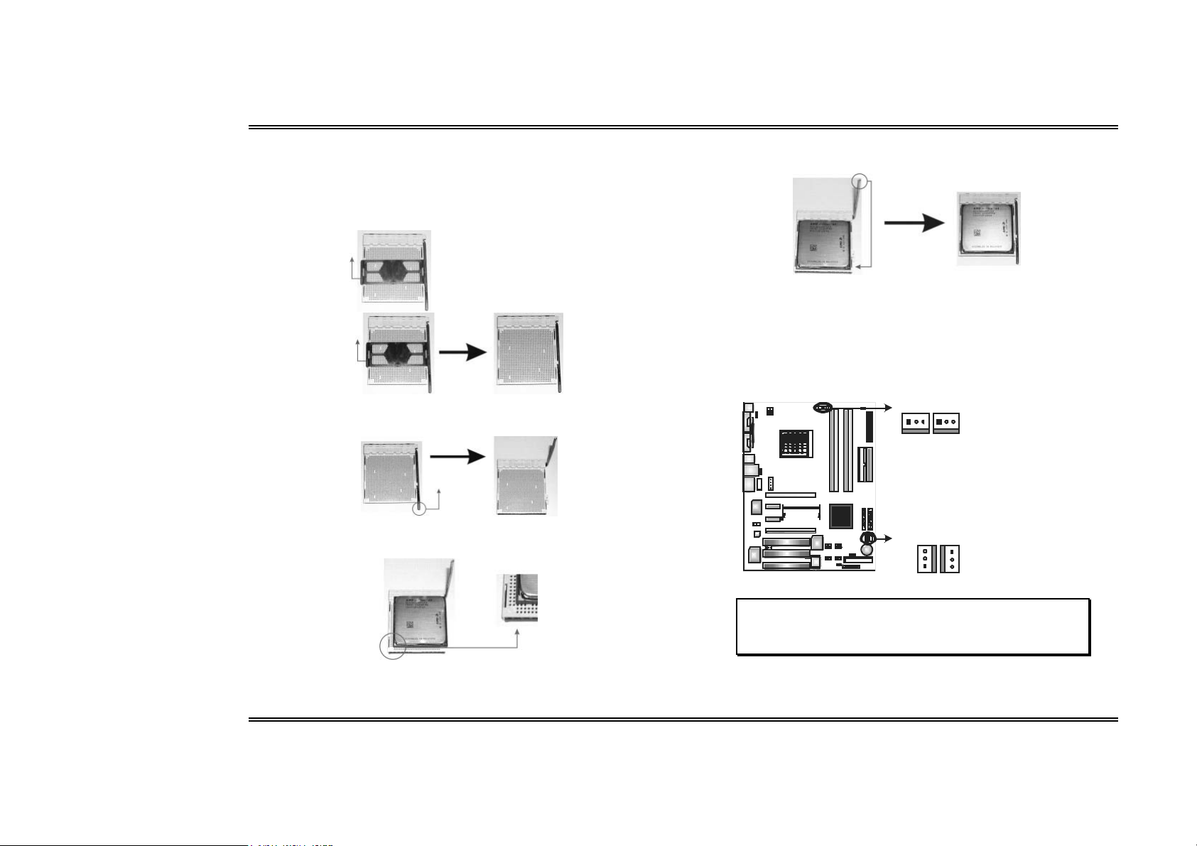
A. Centra l Pro c essing Unit (C PU)
Step 1:
Remove the socket protection cap.
Step 2:
Pull the socket locking lever out from the socket and then raise the lever up to a
90-degree angle.
Step 3:
Look for the triangular cut edge on socket, and the golden dot on CPU should point
towards this triangular cut edge. The CPU will fit only in the correct orientation.
Step 4:
Hold the CPU down firmly, and then lower the lever to locked position to complete the
installation.
Step 5: Put the CPU Fan and heatsink assembly on the CPU and buckle it on the
retention frame. Connect the CPU FAN power cable into the JCFAN1. This compl etes
the installation.
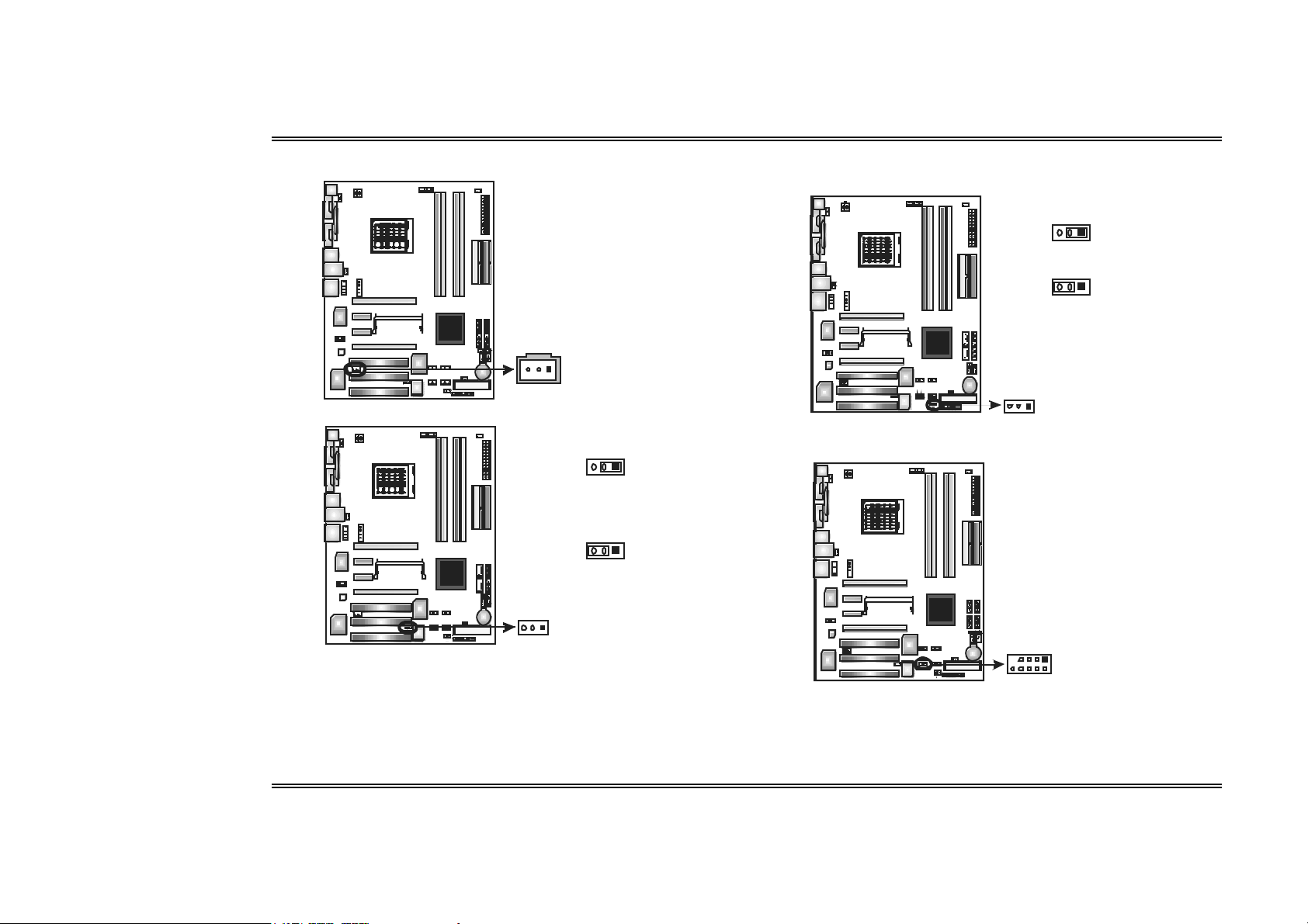
B. About FAN Headers
CPU FAN Power Head er: JCFAN1
S yst em Fan Po wer H eader s: J SFAN1/ JSFAN 2
3
North Bridge Fan Powe r Header: JNBFAN1
JCFAN1JSFAN2
1313
JNBFAN1 JSFAN1
3
1
Note:
JCFAN1 reserves s ystem cooling fan with Smart Fan Control utilities. It supports 3 pin head
connector. When connecting with wires onto connectors, please note that the red wire is the
posi tive and should be c onnected to pin#2, and the bl ack wire is G round and should be
connected to GND.
JCFAN1:
Pin Assignment
1 Ground
2 Smart Fan Cont rol
3 F AN RPM rate
JSF AN2:
Pin Assignment
1 Ground
2 + 12V
3 Ground
JNBF AN1/JSF AN 1:
Pin Assignment
1 Ground
1
2 + 12V
3 F an RPM r ate
3
sens e
Sens e
Us e r’s M anual
Page 7

Biostar T-Series TForce4 SLI
2.2 SYSTEM MEMORY
DIMM1
DIMM2
DIM M4
DIM M3
A. DDR Modules
1. Unlock a DIMM slot by pressing the retaini ng clips outward. Align a DIMM on the
slot such that the notch on the DIMM matches the break on the slot.
2. Insert the DIMM vertically and firmly into the slot until the retaining chip snaps
back in place and the DIMM is properly s eated.
Notes:
To re move the DDR modules , push the ejector tabs at both sides of the slot outw ard at
the same time, and pull the modules out vertic ally.
B. Mem o ry Space
DIMM So cket L ocat io n DDR Module Total Memory Size
DIMM1 128MB /25 6MB /512M B/1GB *1
DIMM2 128MB /25 6MB /512M B/1GB *1
DIMM3 128MB /25 6MB /512M B/1GB *1
DIMM4 128MB /25 6MB /512M B/1GB *1
Max is 4 GB.
C . D D R In sta l lation No ti c e
For AMD K8 939 CPU launched before Rev. E, (see the table below to know
your CPU version) please follow the tabl e below to install your DDR memory
module, or the system may not boot up or may not function properly.
“SS” represents Single Side DDR memory module.
“DS” represents Double Side DDR memory module.
Star sign “*” represents l eave the DIMM socket empty.
DIMM1 SS/DS * SS/DS * SS/DS
DIMM2 * * S S/DS * SS/DS
DIMM3 * SS/DS * SS/DS SS/DS
DIMM4 * * * SS/ DS SS/ DS
D. Know you r CPU Version
AMD Athlon 64 Proces sor Ordering Part Number Example
ADA 3200 A E P 5 AP
AMD Athlon
64 Pro cessor P art Def inition
Part Definition Revision Part Definition Revision
AP Rev C0 BN Rev E4
AR Rev CG BP Rev E3
AS Rev CG BO Rev E3
AW Rev CG BY Rev E6
AX Rev CG BW Rev E6
AZ Rev CG
BI Rev D0
Part Defini ti on: A P = Re v C 0 (see Tabl e 1)
4
Us e r’s M anual
Page 8
Biostar T-Series TForce4 SLI
2.3 PERIPHERAL S
A. Card and I/O Slots:
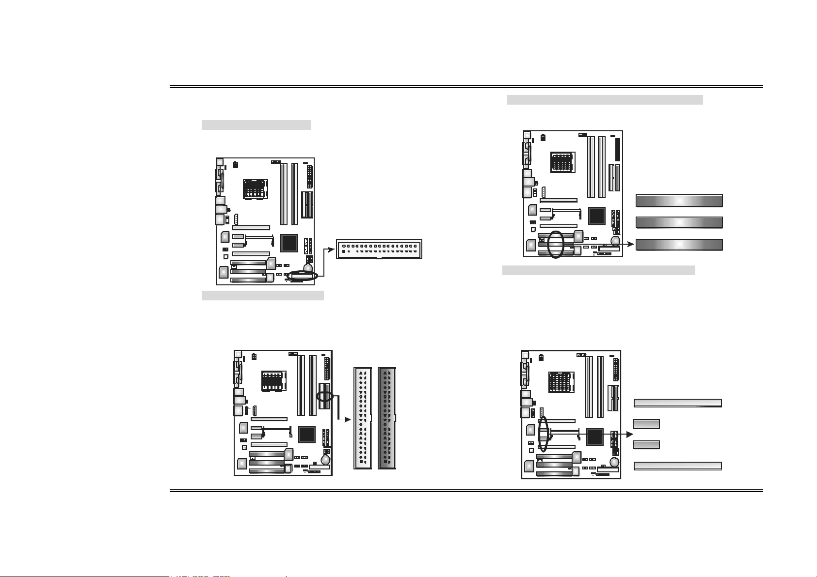
Floppy Di sk Connector: FDD1
The motherboard provides a s tandard floppy disk connector that supports
360K, 720K, 1.2M, 1.44M and 2.88M floppy disk types. This connector
supports the provided floppy drive ri bbon cables.
Hard D isk C onnectors: IDE 1/IDE 2
The motherboard has two 32-bit Enhanced PCI IDE Controllers that provide
PIO Mode 0~4, Bus Master, and Ultra DMA 33/66/100/133 functionality. It
has two HDD connectors IDE1 (primary) and IDE2 (secondary). The IDE
connectors can connect a master and a slave drive, so you can connect up
to four hard disk drives. The first hard drive should always be connected to
IDE1.
2
1
IDE2
IDE1
39 40
Peripheral Component Inter connect Slots: PCI1~PCI3
This motherboard is equipped with 3 standard PCI slots. PCI stands for
Peripheral Component Interconnec t, and it is a bus standard for expansion
cards. T his PCI s lot is desi gnated as 32 bits .
PCI1
PCI2
34
33
PCI3
PCI-Expre ss Slot s: PEX16-1/PEX16-2/ PEX1-1/PEX1-2
PEX16 -1 (Normal Mo de):
- PCI Express 1.0a compliant.
- Maximum bandwidth is up to 4GB/s per direction.
PEX16-1/PEX1-1/PEX1-2 (Normal Mode):
- PCI Express 1.0a compliant.
- Maximum bandwidth is up to 250MB/s per direction.
PEX1 6-1 /PEX16 -2 (SLI Mode):
- PCI Express 1.0a compliant.
- Maximum bandwidth is up to 2GB/s per direction.
12
PEX16- 1
PEX 1-1
PEX1-2
PEX16-2
5
Us e r’s M anual
Page 9
Biostar T-Series TForce4 SLI
B. Conn ectors and Headers:
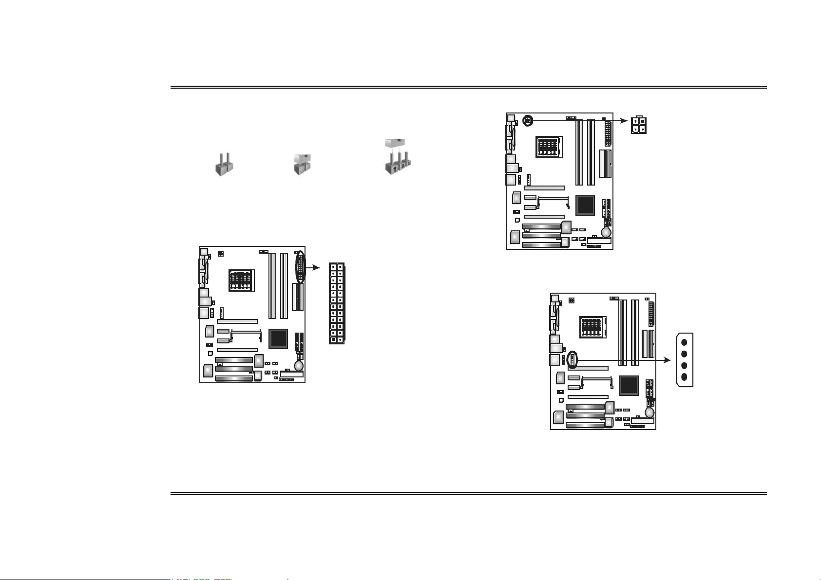
How to se tup J umpers
The illustration shows how to set up jumpers. When the jumper cap is placed on pins,
the jumper is “closed”, if not, that means the jumper is “open”.
Pin ope ned Pin close d Pin1-2 cl osed
ATX P ower Sourc e Connec tor: JATXPWR1
JATXPWR1 allows user to connect 24-pin power connector on the ATX power
supply.
12
12413
Pin Assignment
1 + 3.3V
2 + 3.3V
3 Ground
4 + 5V
5 Ground
6 + 5V
7 Ground
8 PW _OK
9 St andby
Volt age+5V
10 + 12V
11 + 12V
12 Detect
13 + 3.3V
14 -12V
15 Ground
16 PS_ON
17 Ground
18 Ground
19 Ground
20 -5V
21 + 5V
22 + 5V
23 + 5V
24 Gr ound
ATX P ower Sourc e Connec tor: JATXPWR2
By connecting JATXPWR2, it will provide +12V to CPU power circuit.
21
43
Assi gn ment
Pin
1 +12V
2 +12V
3 Gr ound
4 Gr ound
PCI-Express x16 Slot Power Source Conne ctor: JPEXPWR1
When SLI mode is enabled, please plug in this PEX power source connector to
make sure the s ystem is working under a stable environment. Please read Chapter
5 for detail information.
+12V
Ground
Ground
VCC
6
Us e r’s M anual
Page 10
Biostar T-Series TForce4 SLI
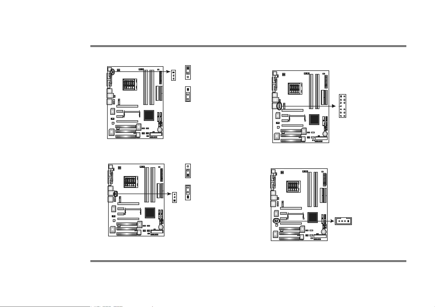
Power Sourc e Heade r for PS/2 Ke yboard/Mouse: JKBMSV1
Pin 1-2 Close: +5V for PS/2 keyboard and mouse.
Pin 2-3 Close: PS/2 keyboard and mouse are powered with +5V standby voltage.
1
1
3
3
Pin 1-2 Close (def ault)
1
3
Pin 2-3 Close
Note: In order to support this f unct io n
“Power-o n system via keyboard an d
mouse” , “JKBMSV1” jump er cap
shoul d be placed o n Pin 2- 3.
Power Sourc e Heade rs for USB Ports at Bac k Panel: J1394_USBV1
Pin 1-2 Close: +5V for USB ports at J1394_USB1 and JUSBLAN1.
Pin 2-3 Close: USB ports at J1394_USB1 and JUSBLAN1 are powered with +5V
standby voltage.
3
1
Pin 1-2 Close (def ault)
3
3
1
1
Pin 2-3 Close
Note:
In order to support this f unct io n
“Power-o n system via USB device,”
J1394 _USBV1 jumper cap should be
place d on Pin 2- 3 individ ually.
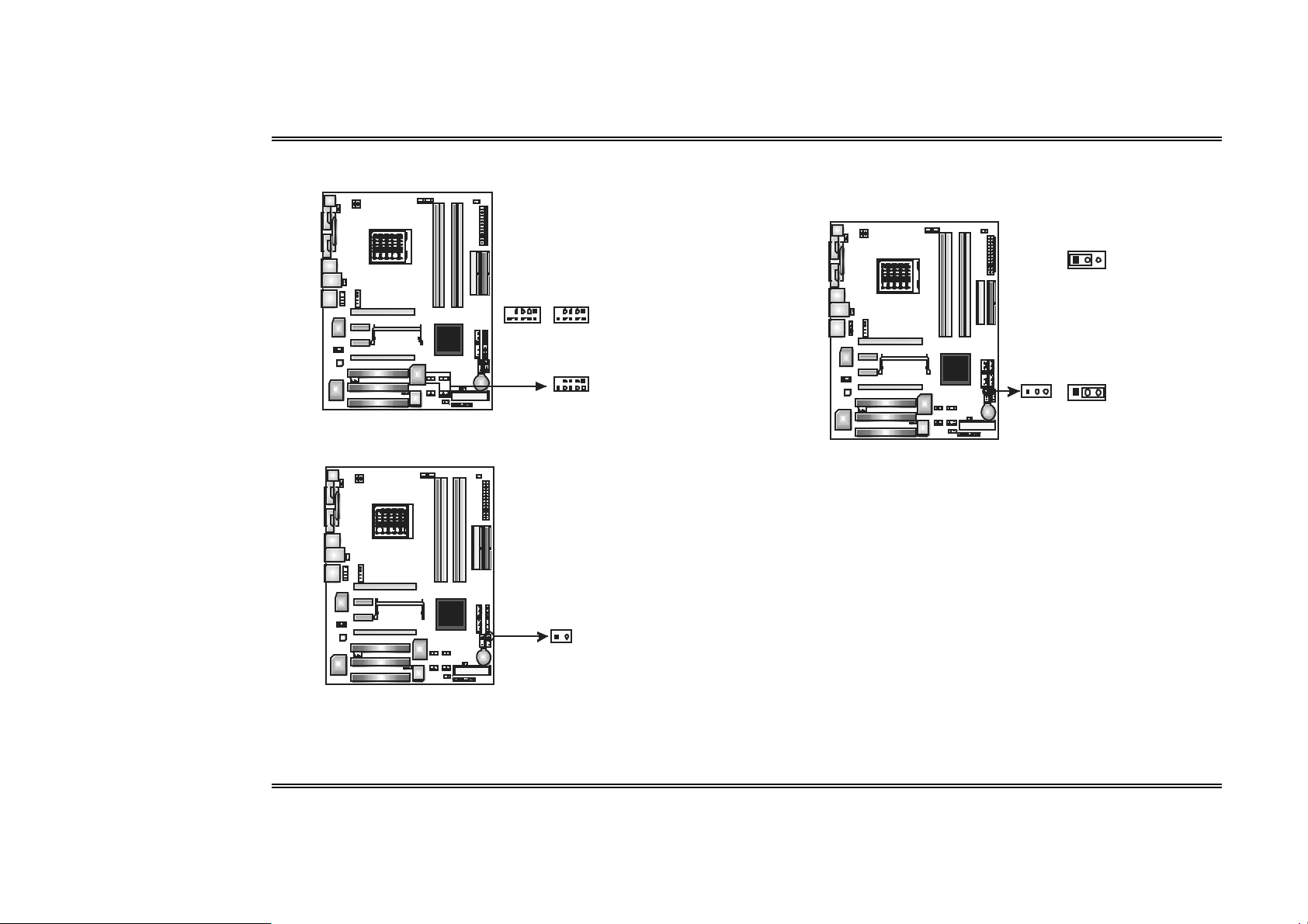
Front Panel Audio-out Heade r: JAUDIO2
This connector will allow user to c onnect with the front audio output headers on the
PC case. It will dis able the output on back panel audio connectors.
1
13
Pin Assignment
1 MI C-in/
2 Gr ound
3 St ereo MI C-in L
4 Audio p ower
5 Right line-o ut /
2
6 Right line-o ut /
7 Reserve d
8 Key
9 Left line- o ut/
14
10 Left line-out/
11 Right li ne- i n
12 Right li ne- i n
13 Lef t line-i n (opt io nal)
14 Lef t line-i n (opt io nal)
St ereo MI C-in R
Speaker -o ut Right .
Speaker -o ut Right
Speaker -o ut Lef t
Speaker -o ut Lef t
(option al)
(option al)
CD-ROM Audio-in Con nector: JCDIN1
This connector allows us er to connect the audio source from a variety of devices,
like CD-ROM, DVD-R OM, PCI sound card, PCI T V tuner card etc.
41
Assi gn ment
Pin
1 Left c hannel inp ut
2 Gr ound
3 Gr ound
4 Right cha nne l inp ut
7
Us e r’s M anual
Page 11
Biostar T-Series TForce4 SLI
Digital Audio-out Co nnector: JSPDIF_OUT
This connector allows us ers to connect the PCI bracket SPDIF output header.
31
Pin
1 +5V
2 SPDIF OUT
3 Gr ound
Assi gn ment
Power Sourc e Heade r for 1394 Chip: J1394PWR1
3
1
Pi n 1- 2 Clo se:
+3.3V for 1394 chipset
(def ault ) .
3
1
Pi n 2- 3 Clo se:
+3.3V SB f or 1394
chipset.
1
3
Power Sourc e Heade r for USB Ports at Front Panel: JUSBV1
Pin 1-2 Close: +5V for USB ports at front panel.
Pin 2-3 Close: USB ports at front panel are powered with +5V standby voltage.
3
1
Pin 1- 2 Cl ose (defa ult)
3
1
Pin 2- 3 Cl ose
Note:
In order to support this f unct io n
“Power-o n system via USB device,”
JUSBV1 jumper cap should be
place d on Pin 2- 3 individ ually.
31
Header for 1394A Firewire Port at Front Panel: J1394A1
This header allows us er to c onnect the front 1394 port for digital image devices.
91
210
Pin
Assi gn ment
1 A+
2 A3 Gr ound
4 Gr ound
5 B+
6 B7 +12v
8 +12V
9 Key
10 Gr ound
8
Us e r’s M anual
Page 12
Biostar T-Series TForce4 SLI
Headers for USB Ports at Front Panel: JUSB1~JU SB3
This connector allows us er to connect additional USB c ables at PC front panel,
and also can be connected with internal USB devices , like USB card reader.
91
JUSB1
JUSB3
Assi gn ment
Pin
1 +5V (f used)
2 +5V (f used)
3 USB4 USB5 USB+
6 USB+
7 Gr ound
8 Gr ound
9 Key
10 NC
JUSB2
210
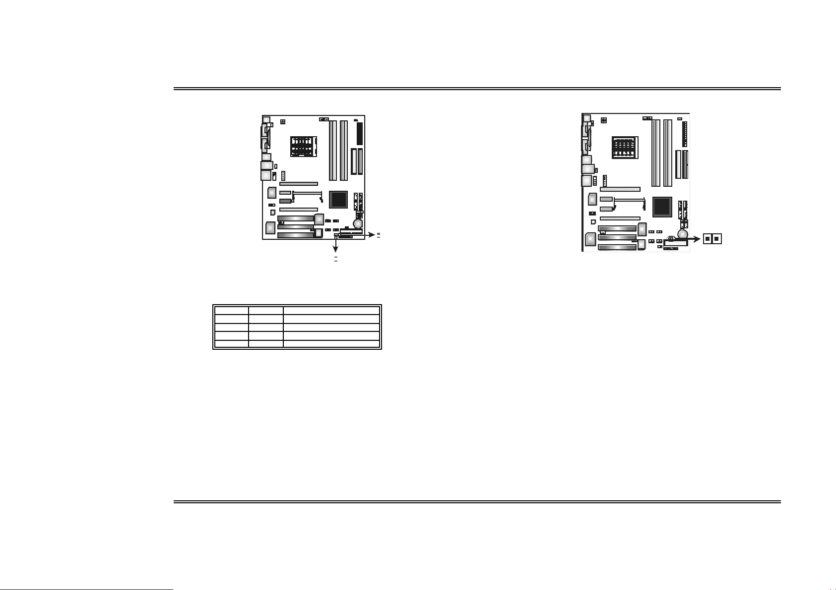
Case Open Header: JCI1
This connector allows s ystem to monitor PC case open status. If the signal has
been triggered, i t will record to the CMOS and show the message on next boot-up.
Assi gn ment
Pin
1 Case op en signal
2 Gr ound
Clear CMOS Header: JCMOS1
By placing the jumper on pin 2-3, it allows user to restore the BIOS safe setting
and the CMOS data, pleas e carefully follow the procedures to avoid damaging the
motherboard.
13
Pin 1- 2 Cl ose:
Normal Oper ation (d efault).
3
1
13
Pin 2- 3 Cl ose:
Clear CMO S dat a.
Clea r CMOS Procedures:※
1. Remove AC power line.
2. Set the jumper to “Pin 2-3 Close”.
3. Wait for five seconds .
4. Set the jumper to “Pin 1-2 Close”.
5. Power on the AC.
6. Reset your desired password or clear the CMOS data.
12
9
Us e r’s M anual
Page 13
Biostar T-Series TForce4 SLI
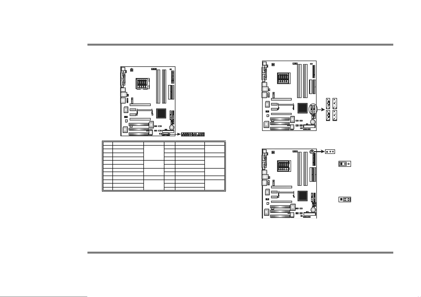
JPANEL1: Header f or Front Panel Facilities
This 24-pin connector includes Power-on, Reset, HDD LED, Power LED, Sleep
button, speaker and IrDA Connection. It allows user to connect the PC case’s front
panel switch functions.
2
1
Pin Assignment Function Pin Assignment Function
1 +5V 2 Sleep contr ol
3 N/A 4 Ground
5 N/ A 6 N/ A N/ A
7 Speaker
9 HDD LED ( + ) 10 Power LED (+ )
11 HDD LED (-)
13 Gr ound 14 Power button
15 Reset cont rol
17 N/A 18 Key
19 N/A 20 Key
21 +5V 22 Gr ound
23 IRTX
Speaker
Conn ect or
Hard driv e
LED
Reset button
IrDA
Conn ect or
8 Power LED (+)
12 Power LED (-)
16 Gr ound
24 IRRX
24
23
Sleep b utt on
Power LED
Power-on
but ton
IrDA
Conn ect or
Serial ATA Co nnec tors: JSAT A1~J SATA4
The motherboard has an SATA Controller in nForce4 SLI with 4 channels SATA
interface; it satisfies the SATA 2.0 spec with transfer rate of 3.0 Gb/s.
JS AT A11J SAT A2
7
4
7
4
1
J SA TA 3 J SAT A4
Pin
Assi gn ment
1 Gr ound
2 TX+
3 TX4 Gr ound
5 RX6 RX+
7 Gr ound
Header for Memory Voltage Overc locking: JDDR_OV>3V
When processing Memory Voltage Overclocking, please place the jumper to
pin1-2 Closed. The Default setting is Pin 2-3 Clos ed.
13
13
Pin 1- 2 Cl ose:
Memory volt age O verclock i ng.
3
1
Pin 2- 3 Cl ose:
Normal status (def a ult ).
Note:
1. When “JDDR_OV> 3V” jumper c ap is plac ed on Pi n 2-3, memory volt ag e can b e
manua lly adjust ed u nder CMOS set up.
2. When “JDDR_OV> 3V” jumper c ap is plac ed on Pi n 1-2, memory volt ag e wil l be fixe d
at 3.3V automatical ly, and can’t be adjust e d under COMS set up.
3. Bef ore sett ing memory volt a ge overcl ockin g, pleas e ensure that your DD R supp ort s up
to 3V. (Consult i ng your DDR suppli er)
10
Us e r’s M anual
Page 14
Biostar T-Series TForce4 SLI
_
_
On-Board LED Indicators
There are 4 LED indicators on the motherboard to show system status .
DIMM
LED
LED_5SB
LED_D1
D2
LED
LED_D1 and LED_D2:
These 2 LED indicate system power on diagnostics.
Please refer to the table below for different messages:
LED_D1 LE D_D2 Messag e
ON ON Normal
ON OFF Memory Error
OFF ON VGA Error
OF F OFF Abnormal: CPU / Chips et error .
LED_DIMM:
This LED indicates the voltage of memory is activated normally.
On-Board Buttons
There are 2 on-board buttons.
RS T SW 2
PSRSW 1
PWRSW:
This is an on-board Power Switch button.
RSTS W:
This is an on-board Reset button.
LED_5SB:
This LED indicates the system is ready for Power-on.
11
Us e r’s M anual
Page 15
Biostar T-Series TForce4 SLI
O
Chapte r 3: NVIDIA SLI Function
3.1 REQUIREMENTS
Only W indows X P supports SLI (Dual Vi deo) functi on.
T wo identical SLI-ready graphics cards that are NVIDIA certified.
T he graphics card driver should support NVIDIA SLI technology.
T he power supply unit must provide at least the minimum power required by the
system, or the system will be uns table.
3.2 PLACIN G T HE SLI-NF4 SEL ECTOR CARD
T here is a pre-installed SLI-NF4 selec tor card on the motherboard. The default
setting is Normal Mode, only supports single graphics card.
To use two graphics cards , firstly, you have to set the selector card to SLI Mode,
to support dual video cards.
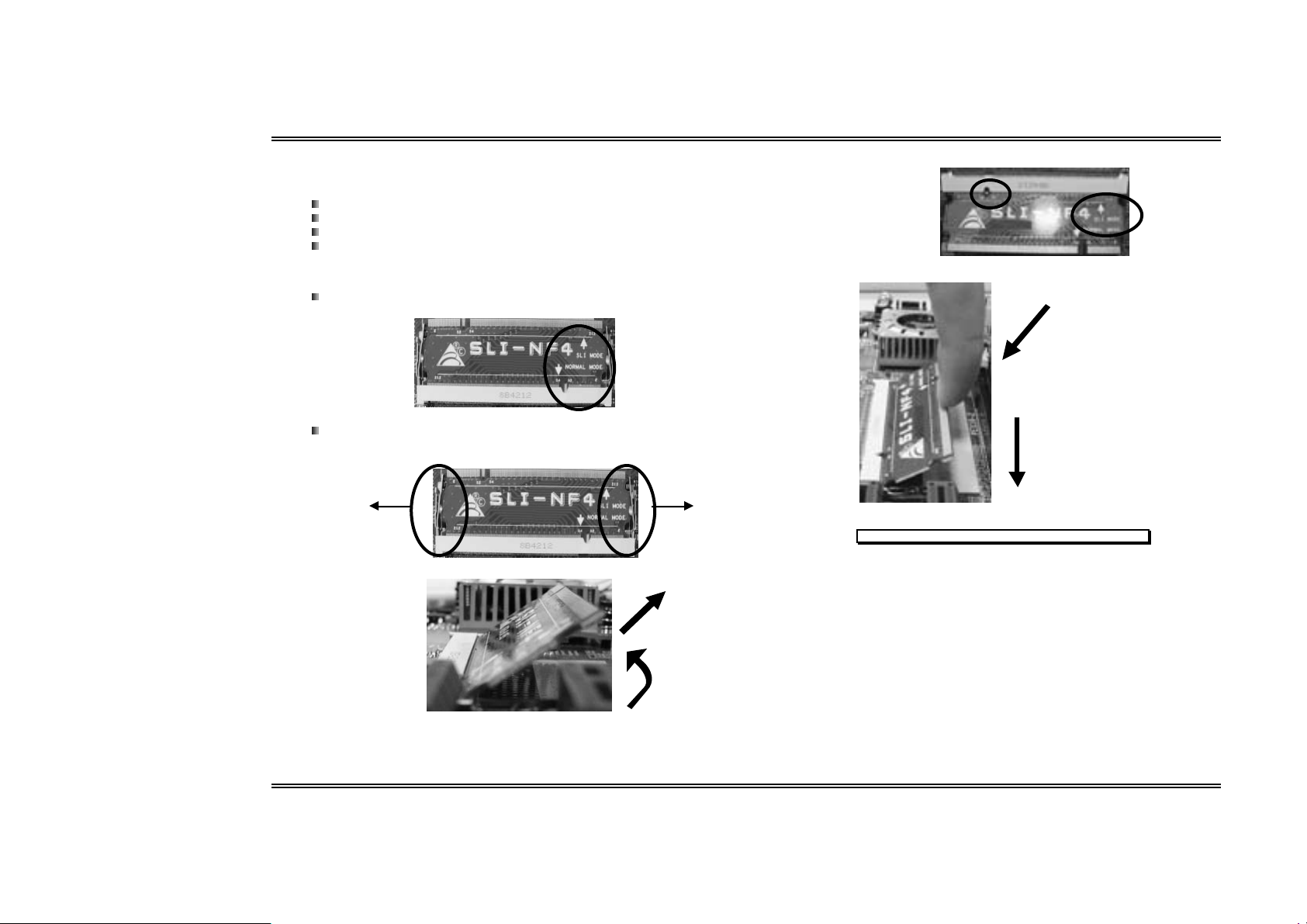
Step 1: Push the retention clips outward to release SLI-NF4 selector card.
Step 2: Pull the selector card out of the slot.
Step 3: Invert the selector card and insert the edge labeled “SLI MODE”.
Step 4: Push down the selector card until the retention clips snap into place.
○1 Insert the card with a
degree about 45
0
.
○2 Push the selector card
downward.
Notice: Make sure to ins ert the card into the slot completely.
○2 pull out the
selector card
1
○
about 45
lift.
degree
12
Us e r’s M anual
Page 16
Biostar T-Series TForce4 SLI
3.3 THINGS TO NOTICE
Normal Mode:
Only PEX16-1 slot supports PCI-Express x16 interface graphics card
function.
PEX16-2, PEX1-1 and PEX1-2 slots provide PCI-Express x1 interface
expansion card function.
SLI M ode :
Use BRI-2 connec tor to l ink two SLI-ready PCI-E x16 interface graphics
cards.
PEX16-1 and PEX16-2 slots provide PCI-E x8 data transfer rate.
PEX1-1 and PEX1-2 slots provide PCI-Express x1 interface expansion
card function.
Coordinate with graphics card driver to set Dual Video function.
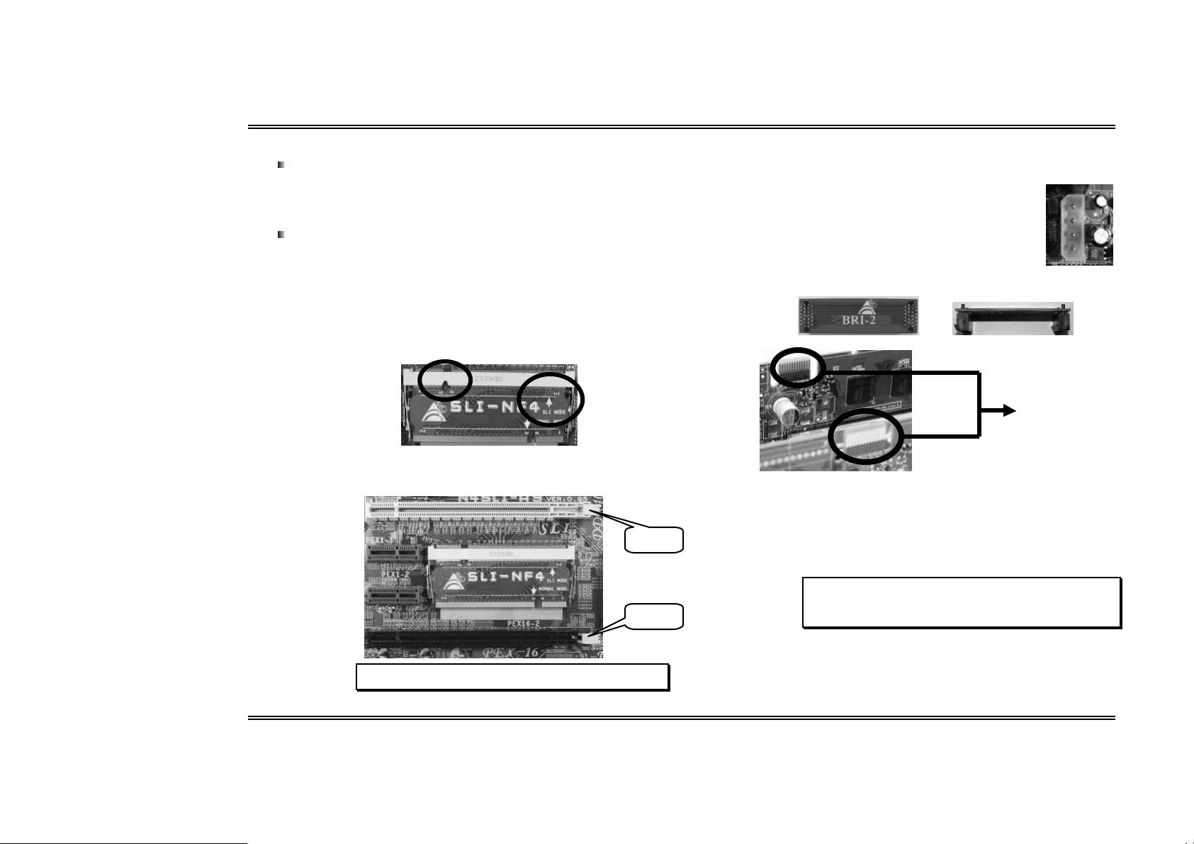
3.4 INSTALLING SLI-READY GRAPHICS CARDS
Step 1 : Make sure th e SLI- NF4 selector card is pla ced at SLI Mode.
Step 2: Prepare two g raphics cards with PCI-E x16 interface.
Step 3: Insert the first one graphics card into the yellow slot (PEX16-1).
Step 4: Insert the second graphics card into the white slot (PEX16-2).
Step 5: Connect a 4- pin ATX power cable to PEX power connector (JPEXPWR1),
this will ensure the stabilization of yo ur system.
No tice:
When und er SLI mode, ple ase make sur e the pow er
supply is at leas t 500W (and a bove).
Step 6: Insert the SLI Bridge (BRI-2) connector on the gold-fingers on each
g ra phi cs ca r d.
Front view Side view
Gold-fing ers on
two graph ics
Step 7: To securely fix the connector between two graphics cards, a retention
bracket must be installed.
PEX 16-1
PEX 16-2
Step 7-1: Remove any of the bracket cover between the two graphics
card s.
Step 7-2: Align and insert the retention bracket into the slot and then
fix it with a screw.
Notice:
1. Make sure the retention bracket supports the SLI Bridge
(BRI-2) f irmly.
2. Retention bracket i s opti onal
Notice: Make sure both the graphics cards are seated into slots
completely.
13
Us e r’s M anual
Page 17
Biostar T-Series TForce4 SLI
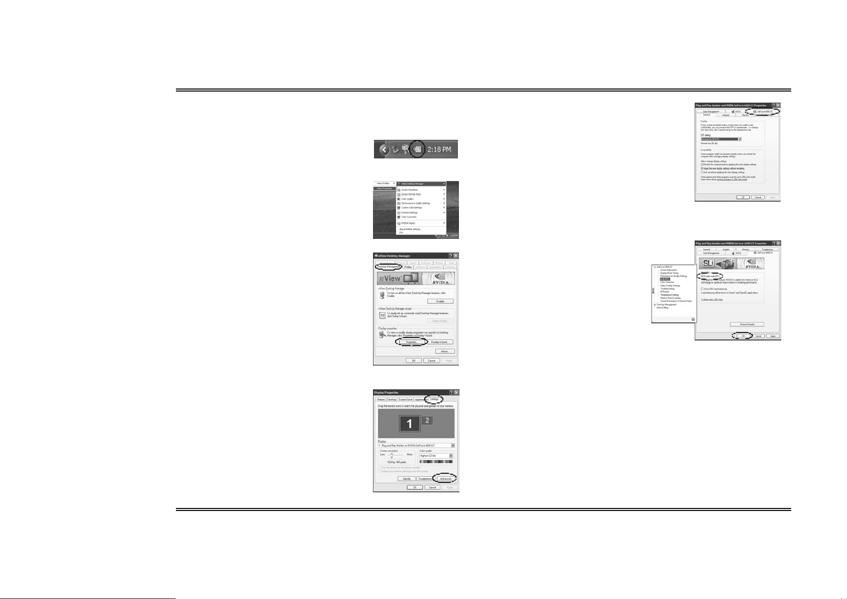
3.5 ENABLING MULTI-GPU FEATURE IN WINDOWS
After the graphics cards are installed, enable the Multi-GPU feature in NVIDIA nView
properties.
Ste p 1 :
Click NVIDIA Settings icon on the Windows
taskbar.
Ste p 2 :
Select nView Proper ties in nView Desktop
Manager pop-up menu.
Ste p 3 :
Click Properties icon in Desktop Management
tab to display Display Properties dialog box.
Ste p 4 :
Click Advanced icon in Settings tab.
Step 5:
Select NVIDIA GeForce tab, and then click on
Multi-GPU item on the left dialog box.
Ste p 6 :
Check b efore Enable SLI
multi- GPU item, and click on OK
to complete the setting.
14
Us e r’s M anual
Page 18
Biostar T-Series TForce4 SLI
Chapte r 4: NVIDIA RAID Functions
4.1 OPERATION SYSTEM
Supports Windows XP Home/Professional Edition, and Windows 2000
Professional.
4.2 RAID ARRAYS
NVRAID supports the following types of RAID arrays:
RAID 0 : RAID 0 defines a disk striping scheme that improves disk read and write times for
many applications.
RAID 1 : RAID 1 defi nes techniques for mirrorin g dat a.
RAID 0 +1: R AID 0+1 combines the techniques used in RAID 0 and R AID 1.
Spanning (JBOD): JBOD provides a method for combining drives of different sizes in to one
large disk.
4.3 HOW RAID WO RKS
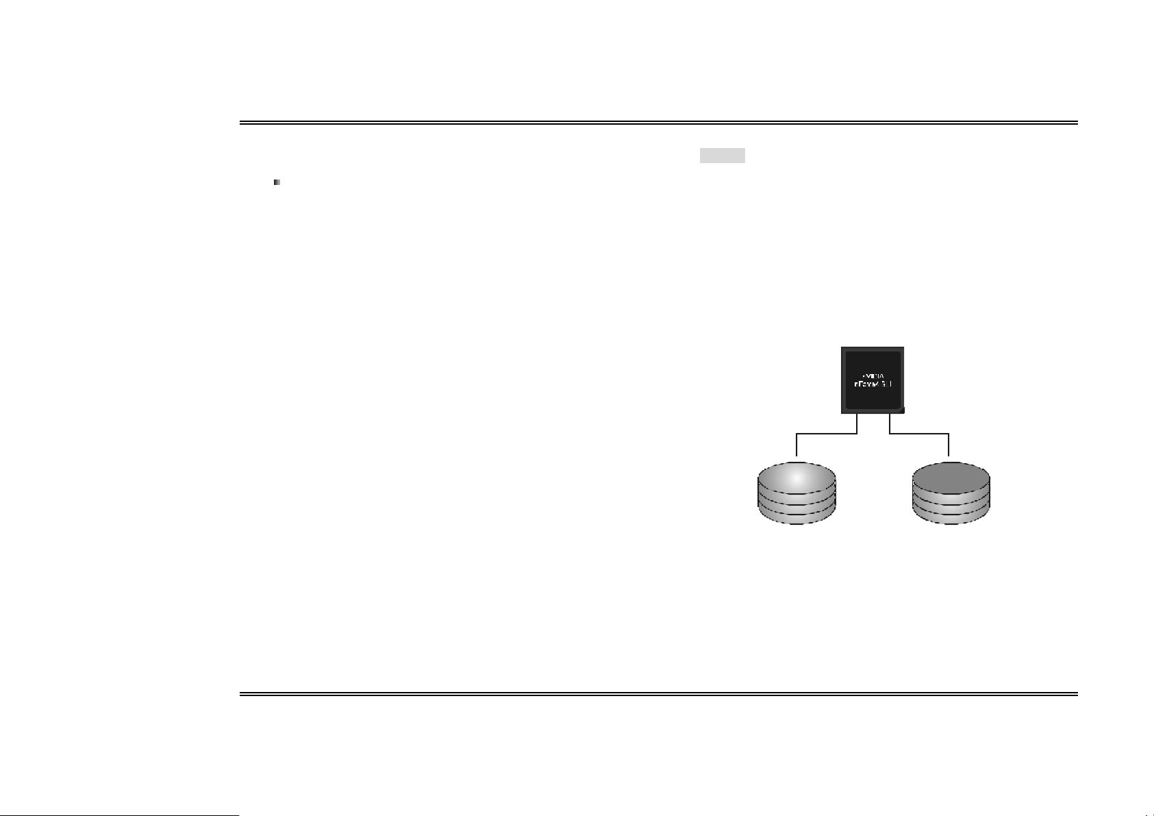
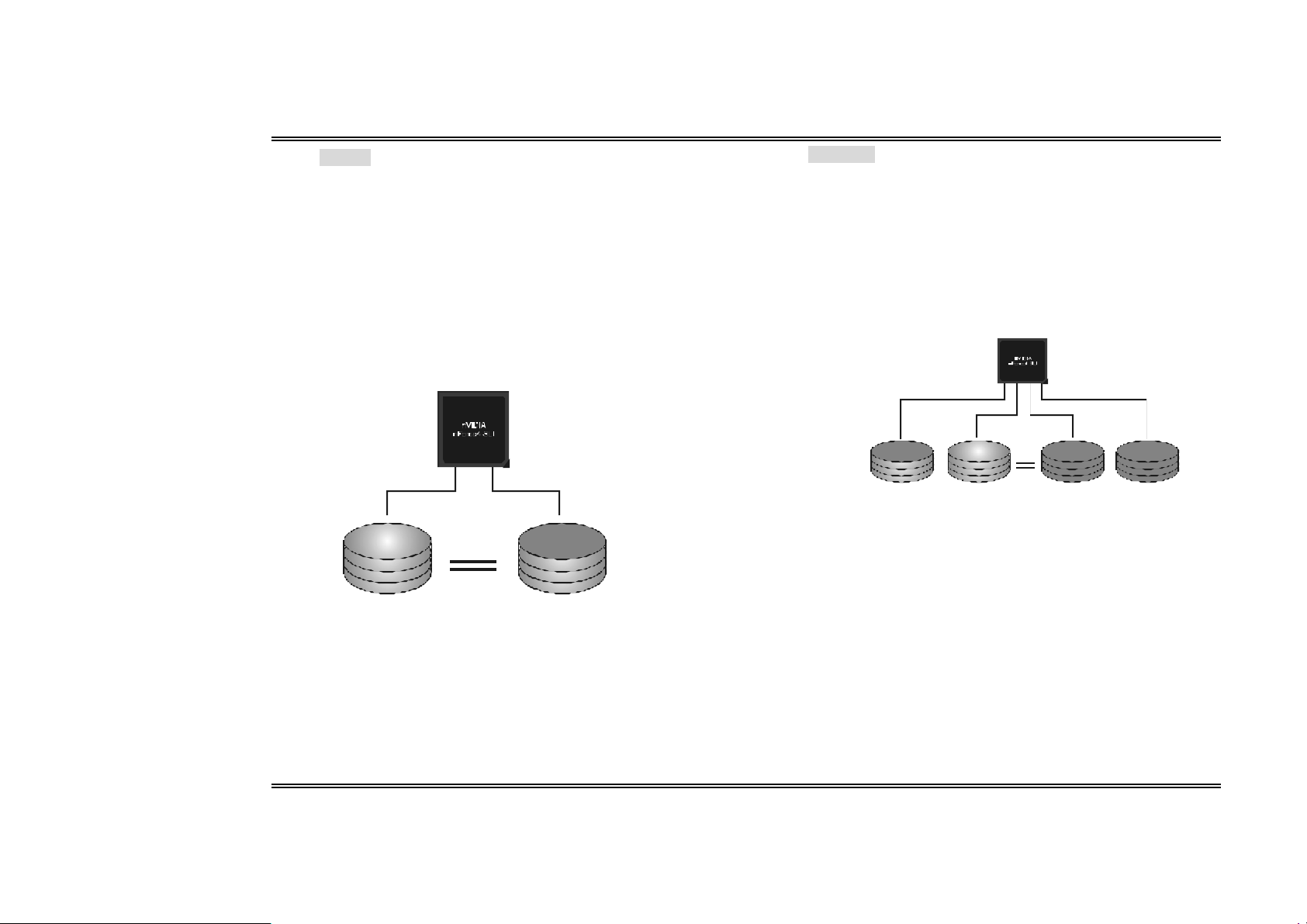
RAID 0:
The contro ller “stripes” data across mu ltiple drives in a RAID 0 array system. It breaks up a
large file in to smaller blocks and performs disk reads an d writes across multiple driv es in
parallel. The s ize o f each b lo ck is determined by the strip e size parameter, which you set
during the creation of the RAID set based on the system environment. This technique reduces
ov erall disk access time and offers high bandwid th.
Features and Benefits
Drives: Mi nimum 1, and maximum is up to 6 or 8. Depending on the platform.
Uses: Intended for non-criti cal data requiring high data throughput, or any
environment that does not require fault tolerance.
B enefits: provides increased data throughput, especial ly for large files. No
capacity loss penalty for parity.
Drawbacks: Does not deliver any fault tolerance. If any drive in the array fails,
all data is lost.
Fa ult Tole ranc e: No.
Blo ck 1
Block 3
Block 5
Block 2
Bl ock 4
Bl ock 6
15
Us e r’s M anual
Page 19
Biostar T-Series TForce4 SLI
RAID 1:
Every read an d write is actu ally carri ed out in parallel across 2 d is k drives in a R AID 1
array system. The mirrored (backup) copy of the data can reside on the same disk or on a
second redundant drive in the array. RAID 1 provides a hot-standby copy of data if the
activ e volume or drive is co rrupt ed or beco mes u navailab le becau se of a hardware failu re.
RAID techniques can be app lied for high -availability so lutions, o r as a fo rm o f auto matic
back up that elimin ates tedious manu al backup s to more expen sive an d less reliable media.
Features and Benefits
Drives: Minimum 2, and maximum is 2.
Uses: RAID 1 is ideal for s mall databases or any other application that
requires fault tolerance and minimal capacity.
Benefits : Provides 100% data redundancy. Should one drive fail, the
controller s witches to the other drive.
Drawbacks: Requires 2 drives for the storage space of one drive.
Performance is impaired during drive rebuilds.
Fault Tolerance: Yes .
Blo ck 1
Block 2
Block 3
Block 1
Block 2
Block 3
RAID 0+1:
RAID 0 driv es can b e mirro red using RAID 1 techniques. Resulting in a RAID 0 +1
solu tio n for improved performan ce plus resilien cy.
Features and Benefits
- Drives: Minimum 4, and maximum is 6 or 8, depending on the platform.
- Benefits : Optimizes for both fault tolerance and performance, allowing for
automatic redundancy. May be simultaneously used with other RAID levels
in an array, and allows for spare disks.
- Drawbacks: Requires twice the available disk space for data redundancy,
the same as RAID level 1.
- Fault Tolerance: Yes .
Block 1
Block 3
Block 5
Block 2
Block 4
Block 6
Block 1
Block 3
Block 5
Block 2
Block 4
Block 6
16
Us e r’s M anual
Page 20
Biostar T-Series TForce4 SLI
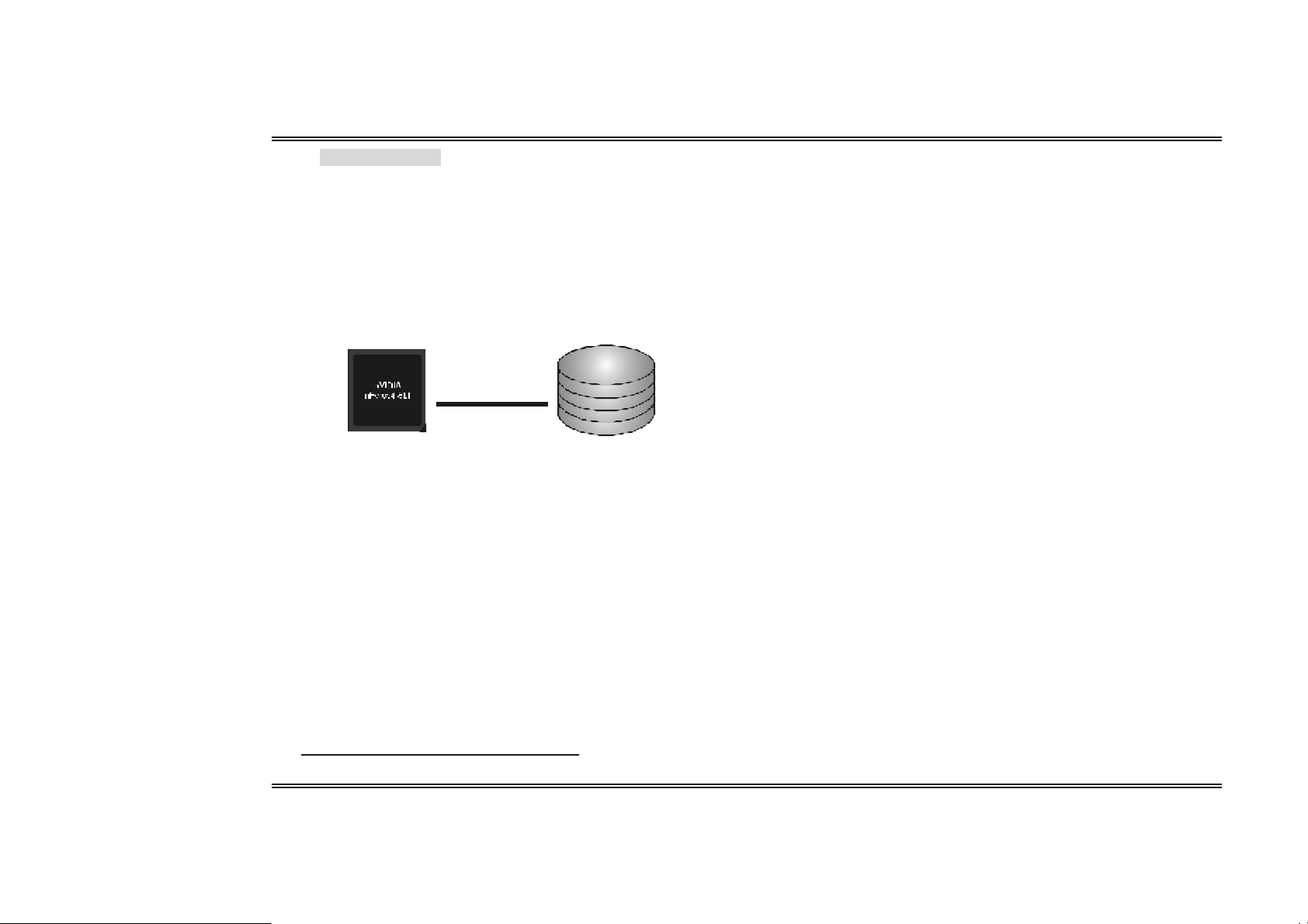
Spanning (JB OD):
JB OD stands for “Ju st a Bun ch of Dis ks”. Each driv e is acces sed as if it were on a
standard SCSI host bus adapter. This is useful when a single drive configuration is needed,
bu t it offers no sp eed improvement or fault tolerance.
Features and Benefits
- Uses: JBOD works best if you have odd sized drives and you want to
combine them to make one big drive.
- Be nefits: JBOD provides the abili ty to combine odd size drives using all of
the capacity of the drives.
- Drawbacks: Decreas es performance because of the difficulty in using
drives concurrently.
- Fault Toler anc e: Ye s .
Single Logical
Drive
Disk 1: 40GB
Disk 2: 80GB
Disk 3: 40GB
Disk 4: 120GB
※ For more detailed setup information, please refer to the Driver CD, or go to
http://www.nvidia.com/page /pg_20011106217193.html to download NVIDIA nForce
Tutorial Flash.
17
Us e r’s M anual
Page 21

Biostar T-Series TForce4 SLI
CHAPT ER 5 : USEFUL HELP
5.1 AWARD BIOS BEEP CODE
Bee p Sound Meaning
One long beep followed by two s hort
beeps
High-low siren sound CPU overheated
One Short beep when system boots-up No error found during POST
Long beeps every other second No DRAM detected or installed
5.2 EXTRA INFORMATION
A. BIOS Update
After you fail to update BIOS or BIOS is invaded by a virus, the Boot-Block function
will help to restore BIOS. If the following message is shown after boot-up of the
system, it means the BIOS contents are corrupted.
In this case, please follow the procedure below to restore the BIOS:
1. Make a bootable floppy disk.
2. Download the Flash Utility “AWDFLASH.exe” from the Biostar website:
www.biostar.com.tw
3. Confirm motherboard model and download the respective BIOS from Biostar
website.
4. Copy “AWDFLASH.exe” and respective BIOS onto floppy disk.
5. Insert the bootable disk i nto floppy drive and press Enter.
6. System will boot-up to DOS prompt.
7. Type “Aw dflash xxxx.bf/sn/py/r” in DOS prompt.
8. System will update BIOS automatically and restart.
9. The BIOS has been recovered and will work properly.
Video card not found or video c ard
memory bad
System wil l s hut down automatically
B. CPU Overheated
If the system shuts down automatically after power on of system for a few
seconds that means the CPU protection function has been activated.
When the CPU is over heated, the motherboard wil l s hutdown automatically to
avoid damaging the CPU, and the system will not power on again.
In this case, please double check:
1. The CPU cooler surface is placed evenly with the CPU surface.
2. CPU fan is rotating normally.
3. CPU fan speed is fulfilling the CPU speed.
After confirmation, pl ease follow the steps below to relieve the CPU protection
function.
1. Remove the power cord from power supply for a few seconds.
2. Wait for a few seconds.
3. Plug in the power cord and boot up the system.
Or you can:
1. Clear the CMOS data.
(See “JCMOS1: Clear CMOS Header” section)
2. Wait for a few seconds.
3. Power on the system again.
18
Us e r’s M anual
Page 22

Biostar T-Series TForce4 SLI
yp
pp
p
5.3 TROUBLESHOOTING
Pr oblem Soluti on
1. No power to the sys tem at all
Power l ight don’t i ll uminate, fan
inside power suppl y does not turn
on.
2. Indi cator light on keyboard does
not turn on.
System inoperative. Keyboard lights are
on, power indicator lights are lit, and hard
drive is spinning.
System does not boot from hard disk
drive, can be booted from optical drive.
System only boots from optical drive.
Hard disk can be read and applications
can be used but booting from hard disk is
impossible.
Screen message says “Invalid
Configuration” or “CMOS Failure.”
Cannot boot system after ins talling
sec ond hard drive.
1. Make sure power cable is securely
plugged i n.
2. Replace cable.
3. Contact technical support.
Using even pressure on both ends of the
DIMM, press down firmly until the module
snaps into pl ace.
1. Check c able running from disk to
disk controller board. Make sure
both ends are securely plugged in;
check the drive t
CMOS setup.
2. Backing up the hard drive is
extremely important. All hard disks
are capable of breaking down at
any time.
1. Back up data and a
2. Reformat the hard drive. Re-install
applications and data us ing bac kup
disks.
Review system’s equipment. Make sure
correct information is in setup.
1. Set master/slave jumpers correctly.
2. Run SETUP program and select
correct drive types. Call the drive
manufacturers for c om
other drives.
e in the standard
lication files.
atibility with
19
Us e r’s M anual
Page 23

Biostar T-Series TForce4 SLI
Ge rm an
CPU
Unterstützt Sockel 939.
Unterstützt AMD Athlon 64 FX- / Athlon 64- / Athlon 64 X2-Prozessoren.
AMD 64-Architektur ermöglicht 32- und 64-Bit-Verarbeitung.
Unterstützt HyperTrans port™- ud AMD Cool’n’Quiet™-Technologie.
Chipsatz
NVIDIA nForce4 SLI:
Unterstützt NVIDIA Firewall.
Unterstützt Gigabit Ethernet.
Unterstützt NVIDIA nTune Utility.
Unterstützt NVIDIA Sec ure Networking Processor.
Betriebssyste munterstützung
Unterstützt Windows 2000 und Windows XP.
Hinweis: Windows 98SE und W indows ME werden nic ht unterstützt.
Abmessungen
ATX-Formfaktor: 29.4cm (L) x 24.35cm (B)
S yst em spei cher
Unterstützt Dual-Kanal DDR.
Unterstützt DDR333 / DDR400.
Unterstützt die Speichergröße von maximal 4GB mit 4 DIMM-Steckplätze.
Serial ATA II
nForce4 SLI unterstützt die Serial ATA 2.0-Spezifikation, datentransferrate von
bis zu 3GB/s.
Super E/A
Chip: ITE IT 8712F.
Systemumgebungskontrolle:
Hardwareüberwachung
Lüfterdrehzahl-Controller
"Smart Guardian"-Funktion von ITE
IDE
Zwei integrierte Anschl üsse für 4 Geräte.
Unterstützt PIO-Modus 0-4, Blockmodus und Ultra DMA 33/66/100/133
Bus-Mastermodus.
AC’97 Audio Sound Codec
Chip: ALC850, unterstützt 8 Kanäle.
IEEE 1394A C hip
Chip: VIA VT6307, unterstützt zwei 1394A Firewire-Ans chlüsse jeweils mit einer
Geschwindigkeit von bis zu 400Mb/s.
Gigabit Ethern et-LAN
NVIDIA Gigabit MAC + VITESSE Gigabit PHY VSC8201.
Unterstützt die ACPI-Energieverwaltung.
Unterstützt NVIDIA StreamThru-Technologie
Isochroner Controller gekoppelt mit Hyper Transport garanti ert höchste
Netzwerkleistung.
Sicherh eit
NVIDIA Firewall-Technologie
Native Firewall-Lösung, schützt den PC durch Filtern unautorisierten
Datenverkehrs vor Eindringlingen.
NVIDIA R AID Technologie
RAID 0 Disk-Striping für die höchste System- und Applikationsleistung.
RAID 1 Disk-Mirroring zur Erhöhung der Fehlertoleranz,
unterstützt die SATA und ATA-133 Disk-Controller-Standards.
RAID 0+1 Disk-Striping und -Mirroring für di e höchste Leistung mit
Fehlertoleranz.
Interne in tegri erte St eckp lät ze und Anschlüsse
No rmal-Mo dus PCI-Ex press -Steckplätze:
- Ein PCI-Express x16-Steckplatz: PEX16-1.
- Drei PCI-Expres s x1-Steckplätze: PEX16-2, PCI-EX1-1 und PCI-EX1-2.
SLI-Modus PCI-Express-Steckplätze:
- Zwei PCI-Express x8-Steckplätze: PEX16-1 und PEX16-2.
- Zwei PCI-Express x1-Steckplätze: PEX1-1 und PEX1-2.
Hi nw eis:
Der Normalmod us und SLI -Mo dus wir d durch die SLI-NF4 Auswa hlkart e um gesch altet.
(Einzel heite n hierz u finden Sie im Kapitel 3.)
1 CD-ROM-Audioeingang
1 S/PDIF-Ausgangsanschluss
2 Ultra DMA 133/100/66/33 IDE-Anschlüsse
3 PCI-Steckplätze
4 Serial ATA II-Anschlüsse
Rücktafel-E/ A-An schlüs se
1 drucker Anschluss
1 RJ-45 LAN-Anschluss
1 PS/2-Mausanschluss
1 PS/2-Tastaturansc hluss
1 1394A Firewire-Anschluss
1 serieller Anschluss (COM2 optional)
4 USB 2.0-Anschlüsse
6 Audioansc hlüsse für 8-Kanal-Audioausgabefunktionen.
20
Us e r’s M anual
Page 24

Biostar T-Series TForce4 SLI
Fr e nch
Processeur
Supporte le socket 939.
Supporte les processeurs AMD Athlon 64 FX / Athlon 64 /Athlon 64 X2.
Architecture AMD 64 activant des operations 32 et 64 bits.
Supporte les technologies HyperTransport™ et AMD Cool’n’Quiet™
Chipset
NVIDIA nForce4 SLI:
Supporte le firewall NVIDIA.
Supporte l’éthernet Gigabit.
Supporte l’utilitaire NVIDIA “nTune Utility”.
Supporte le processeur NVIDIA de réseau sécuritaire (Secure
Networking).
S yst èm es d 'exp loitat io n p ri s en ch arge
Prise en charge de Windows 2000 et Windows XP.
Note: Windows 98SE et Windows ME ne sont pas pris en charge.
Dimensions
Facteur de forme AT X: 29.4c m (Long) x 24.35cm (Larg)
Mémoire s yst ème
Prise en charge des DDR double canal
Prise en charge de DDR333 / DDR400.
Espace mémoire maximum de 4GB, prenant en charge 4 barrettes DIMM.
AT A I I S é r i e
nForce4 SLI prise en charge des spéci fic ations ATA 2.0 Série, débit de
transfert des données jusqu'à 3 Go/s.
E/S disque
Chip: ITE IT 8712F.
Initiatives Contrôle d'environnement,
Moniteur matériel
Contrôleur de vitesse de ventilateur
Fonction "Smart Guardian" d'ITE
IDE
Deux connecteurs sur carte permettant la prise en charge de 4 périphériques .
Prise en charge PIO mode 0-4, Block Mode et mode bus maître Ultra DMA
33/66/100/133.
Ch ip IEEE 1394 A
Chip: VIA VT 6307, prise en charge de deux ports 1394A Firewire jusqu'à 400Mo/s
par port.
Codec audio AC’97
Chip: ALC850, prise en c harge 8 canaux.
LAN Ethernet Gigabit
NVIDIA Gigabit MAC + VITESSE Gigabit PHY VSC8201.
Prise en charge Gestion de l'alimentation ACPI.
Prise en charge de la technologie NVIDIA StreamT hru
Contrôleur isochrone couple l'Hyper Transport donnant des
performanc es réseau plus rapides.
Sécurit é
Technologie de Firewall NVIDIA
Solution de firewall natif, protégeant le PC des intrusions extérieures en
filtrant le trafic non autorisé.NVIDIA Fi rewall technology.
Technologie d e NVIDIA RAID
Stripping de disque RAID 0 pour des performances système et applications
optimales.
Prise en charge mirroring RAID 1 pour tolérance d'erreurs,
prise en charge pour le4s normes contrôleurs de disque SATA et ATA-133.
Disques RAID 0+1 en miroir ou en striping pour des performances plus élevées
et une plus grande résis tance aux pannes.
Emplac ements et connecteurs sur carte internes
Empla cement PCI-Expres s mode norma l :
- Un emplacement PCI-Express x16: PEX16-1.
- Trois emplacements PCI-Express x1: PEX16-2, PEX1-1 et PEX1-2.
Empla cements PCI-Ex press mo de SL I :
- Deux emplacements PCI-Express x8: PEX16-1 et PEX16-2.
- Deux emplacements PCI-Express x1: PEX1-1 et PEX1-2.
Rema rqu e: Le Mode N ormal et le Mo de SLI s ont bascu lés par la c art e sélecteur SLI -NF 4.
(Veuill ez lire le Chapitr e 3 po ur de pl us ampl es infor mat i ons. )
1 connecteur S/PDIF-out
1 connecteur d'entrée CD-ROM audio-i n
2 connecteurs IDE Ultra DMA 133/100/66/33
3 emplacements PCI
4 ports série ATA II
Connecteurs E/S pan n eau arrièr e
1 port imprimeur
1 prise LAN RJ -45
1 port souris PS/2
1 port clavier PS/2
1 port 1394A Firewire
1 port série (COM2 en option)
4 ports USB 2.0
6 ports audio prenant en charge les équipements de sortie audio 8 voies.
21
Us e r’s M anual
Page 25

Biostar T-Series TForce4 SLI
Italian
CPU
Supporto di Socket 939.
Supporto di processori AMD Athlon 64 FX / Athlon 64 / Athlon 64 X2.
L’architettura AMD 64 abili ta la c omputazione simultanea 32 e 64 bit.
Supporto delle tecnologie HyperT ransport™ e AMD Cool’n’ Quiet™.
Chipset
NVIDIA nForce4 CK8-04 SLI:
Supporto di NVIDIA Firewal l.
Supporto di Gigabit Ethernet.
Supporto di NVIDIA nTune Utility.
Supporto del processore NVIDIA Secure Networking.
Sistemi operativi supportati
Supporto di Windows 2000 e Windows XP.
Nota: Non supporta Windows 98SE e Windows ME.
Dimensioni
Fattore di forma AT X: 29.4 cm (L) x 24.35 cm (P)
Memoria di si stema
Supporto di moduli DDR a doppio canale.
Supporto di DDR333 / DDR400.
Lo spazio massimo di memoria è 4GB e supporta 4 prese DIMM.
Serial ATA II
nForc e4 SLI supporto specifiche Serial ATA 2.0, velocità di trasferimento dei dati
fino 3GB/s.
Super I/ O
Chip: ITE IT 8712F.
Funzioni di controllo dell ’ambiente:
Monitoraggio hardware
Controller velocità ventolina
Funzione "Smart Guardian" di ITE
IDE
Due connettori integrati supportano 4 dispositivi.
Modalità: PIO 0-4, bus master Block e Ultra DMA 33/66/100/133.
Audio Codec AC’97
Chip: ALC850, supporto di 8 canali.
Ch ip IEEE 1394 A
Chip: VIA VT 6307, supporto di due porte Firewire 1394A con capacità massima
individuale di 400Mb/s.
Gigabit Ethern et LAN
NVIDIA Gigabit MAC + VITESSE Gigabit PHY VSC8201.
Supporto gestione energetica ACPI.
Supporto della tecnologia NVIDIA StreamT hru
Il controller isocrono accoppiato con Hyper Transport produce le più
veloci prestazioni di rete.
Protezione
Tecnologia Firewall NVIDIA
Soluzione Firewall Native protegge il PC da intrusi oni filtrando il traffic o
non autorizzato.
Tecnologia NVIDIA RAID
Striping del disco RAID 0 per prestazioni s uperiori del sistema e delle
applicazioni.
Supporto mirroring del disco RAID 1 per la tolleranza errori, supporto di entrambi
gli standard controller disco SATA e ATA-133.
Stripinig e mirroring disco RAID 0+1 per le massime prestazi oni c on tolleranza
agli erro ri.
Connettori e alloggi amenti interni integrato
Alloggia menti PCI-Ex press mo dalità normale:
- Un alloggiamento PCI-Express x16: PEX16-1.
- Tre alloggiamenti PCI-Express x1: PEX16-2, PEX1-1 e PEX1-2.
Alloggia menti PCI-Ex press mo dalità SLI:
- Due alloggiamenti PCI-Express x8: PEX16-1 e PEX16-2.
- Due alloggiamenti PCI-Express x1: PEX1-1 e PEX1-2.
Avvi so: La modalit à norm ale e l a moda lit à SLI sono cam biat e d all a sched a di selezio ne
SLI -NF 4. (Fare rifer iment o al C apit o lo 3 per infor mazi oni d ettagliate. )
1 connettore S/PDIF-out
1 connettore ingresso audio CD-ROM
2 connettori Ultra DMA 133/100/66/33 IDE
3 alloggiamenti PCI
4 porte Serial ATA II
Connettori I/O del pann ello po st eriore
1 porta stampatore
1 connettore LAN RJ-45
1 porta mouse PS/2
1 porta tastiera PS/2
1 porta Firewire 1394A (optional )
1 porta seriale (COM2 optional)
4 porte USB 2.0
6 porte audio supportano 8 canali di servizio rendi mento audio.
22
Us e r’s M anual
Page 26

Biostar T-Series TForce4 SLI
Spanis h
Procesador
Soporta el Socket 939.
Supporta los procesadores AMD Athlon 64 FX / Athlon 64 /Athlon 64 X2.
La arquitectura AMD 64 permite computación de 32 bits y 64 bits de manera
simultánea.
Suporta las tecnologías HyperTrans port™ y AMD Cool’n’Qui et™.
Conjunto de chips
NVIDIA nForce4 SLI:
Soporta el Firewall NVIDIA.
Soporta Gi gabit Ethernet.
Suporta la Utilidad NVIDIA nTune.
Suporta el Proc esador para Seguridad en Redes NVIDIA.
Sist em as op erativos comp atib les
Compatible con Windows 2000 y Windows XP.
Nota: no compatible con Windows 98SE ni Wi ndow s ME.
Dimensiones
Formato ATX: 29.4cm (LA) x 24.35cm (AN)
Memoria de l sistema
Compatible con admite DDR de canal dual.
Compatible con Admite DDR333 / DDR400.
Espacio máximo de memoria de 4 GB, que admite 4 zócalos DIMM.
Serial ATA II
nForc e4 SLI compatible con la especificación Serial ATA 2.0, tasa de
transferencia de datos de hasta 3 GB/s.
Súper E/ S
Procesador:IT E IT 8712F.
Iniciativas de control medioambiental:
Supervisor H/W
Controlador de la velocidad del ventilador
Función "Guardián inteligente" de ITE
IDE
Dos conectores integrados que admiten 4 dispositivos.
Admite el modo PIO 0-4, el modo de bloque y el modo de bus maestro Ultra DMA
33/66/100/133.
Códec de audio AC’97
Chip: ALC850, admite 8 c anales.
Procesador I EEE 1394A
Procesador:VIA VT6307, admite dos puertos 1394A Firewire de hasta
400 Mb/s individualmente.
23
LAN Ethernet Gigabit
NVIDIA Gigabit MAC + VITESSE Gigabit PHY VSC8201.
Admite administraci ón de energía ACPI.
Admite la tecnología NVIDIA StreamT hru
Controlador isócrono asociado c on Hyper Transport proporciona el
mayor rendimiento para interconexión en red.
Seguridad
Tecnología de Firewall NVIDIA
- Solución de firewall nativa, protege el computador personal de intrusos
al filtrar el tráfico no autorizado.
Tecnología NVIDI A R AID
Intercalac ión de disco RAID 0 dis k para conseguir el mejor rendimiento del
sistema y de las aplicaciones.
Admite simetría de disco RAID 1 para tolerancia de errores,
compatible con las normas de controlador de discos SATA y ATA-133.
Doble escritura y grabación en disco RAID 0+1 para obtener un mayor
rendimiento con tolerancia a fallos .
Conectores y ranur as integrados e internos
Ranuras PCI-Express para modo norma l:
- Una ranura 16X PCI-Express: PEX16-1.
- Tres ranuras PCI-Express 1X: PEX16-2, PEX1-1 y PEX1-2.
Ranuras PCI-Express para modo SLI:
- Dos ranuras PCI-Express 8X: PEX16-1 y PEX16-2.
- Dos ranuras PCI-Express 1X: PEX1-1 y PEX1-2.
Avi so:
La tarjet a del s elect or SLI -NF4 co nmut a entre el mo do norm al y el modo SLI.
(Consulte el Capí tulo 3 par a obt ener inf ormac ión d et all ada. )
1 conector de salida S/PDIF
1 conector de entrada de audio en CD-ROM
2 conectores Ultra DMA 133/100/66/33 IDE
3 ranuras PCI
4 puertos Serial ATA II
Conectores d e E/S del panel posterior
1 puerto impresora
1 conector de red LAN RJ-45
1 puerto para ratón PS/2
1 puerto para teclado PS/2
1 puerto 1394A Firewire
1 puerto serie (COM2 opcional)
4 puertos USB 2.0
6 puertos de audio que admiten 8 conexiones de salida de audio de 8 canales.
Us e r’s M anual
Page 27

Biostar T-Series TForce4 SLI
Po r tug ues e
CPU
Suporta o socket 939.
Suporta processadores AMD Athlon 64 FX / Athlon 64 / Athlon 64 X2.
A arquitectura AMD 64 permite uma computação de 32 e 64 bits em
simultâneo.
Suporta a tecnologia HyperTransport™ e AMD Cool’n’ Quiet™
Chipset
NVIDIA nForce4 SLI:
Suporta a firewall NVIDIA.
Suporta a Ethernet Gigabit.
Suporta o utilitário NVIDIA nTune.
Suporta o processador NVIDIA Secure Networking.
Sistemas operativos suportados:
Suporta o Windows 2000 e o Windows XP.
Nota: Não suporta o Windows 98SE e o Windows ME.
Dimensões
Factor de forma AT X: 29.4c m (C) x 24.35cm (L)
Memória do sistem a
Suporta DDR de duplo canal.
Suporta módulos DDR333 / DDR400.
Capacidade máxima da memória: 4GB, suportando 4 sockets DIMM.
Serial ATA II
nForc e4 SLI suporta a especificaç ão Serial ATA 2.0, velocidade de transferência
de dados até3 GB/s.
Especific ação Super I/O
Chip: ITE IT 8712F.
Iniciativas para controlo do ambiente,
Monitorização do hardware
Controlador da velocidade da ventoinha
Função "Smart Guardian" da ITE
IDE
Dois conectores na placa para 4 dispositivos.
Suporta o modo PIO 0-4, o modo Block e o modo bus master Ultra DMA
33/66/100/133.
Codec de som AC' 97
Chip: ALC850, suporta 8 canais.
Ch ip IEEE 1394 A
Chip: VIA VT 6307, suporta duas portas Firewire 1394A até 400 Mb/s para cada uma.
LAN Ethernet Gigabit
NVIDIA Gigabit MAC + VITESSE Gigabit PHY VSC8201.
Suporta a gestão de energia ACPI.
Suporta a tecnologia NVIDIA StreamThru
Controlador isócrono combinado com a arquitectura Hyper T ransport
para um desempenho mais rápido ao nível da rede.
Segurança
Tecnologia de firewall NVIDIA
Firewall nativa, para protecção do PC contra intrusos através da
filtragem de tráfego não autorizado.
Tecnologia NVIDIA RAID
RAID 0 função "disk striping" para um melhor desempenho por parte do sistema
e das aplicações .
RAID 1 suporta a função "disk mirroring" para tolerância de falhas,
suporta as normas SATA e ATA-133 ao nível do controlador do disco.
Suporta as funções RAID 0+1 “disk striping” e “mirroring” para um desempenho
superior com tolerância de falhas.
Ranhuras de expansão
Ranhuras PCI-Express de modo normal:
- Uma ranhura PCI Express x16:PEX16-1.
- Três ranhuras PCI Express x1: PEX16-2, PEX1-1 e PEX1-2.
Ranhuras PCI-Express de modo SLI:
- Duas ranhuras PCI Express x8: PEX16-1 e PEX16-2.
- Duas ranhuras PCI Express x1. PEX1-1 e PEX1-2.
Advertência:
É poss ível alt ernar ent re os modos Norma l e SLI através da pl aca sel ect ora
SLI -NF 4. (Leia o Ca pí tulo 3 par a mais inf orm ações. )
1 conector S/PDIF-Out
1 conector CD-ROM para entrada de áudio
2 conectores Ultra DMA 133/100/66/33 IDE
3 ranhuras PCI
4 portas Serial ATA II
Conectores I/O do pain el traseiro
1 porta impressora
1 tomada LAN RJ -45
1 porta para rato PS/2
1 porta para teclado PS/2
1 porta Firewire 1394A
1 porta série. (COM2 opcional)
4 portas USB 2.0
6 portas de áudio para saída de 8 c anais de áudio.
24
Us e r’s M anual
Page 28

Biostar T-Series TForce4 SLI
Poland
Procesor
Obs ługa gniazd Socket 939.
Obs ługa procesorów AMD Athlon 64 FX / Athlon 64 / Athlon 64 X2.
Architektura AMD 64 umożli wi ająca jednoczesne przetwarzanie 32 i 64
bitowe.
Obs ługa technologii HyperTransport™ oraz AMD Cool’n’Quiet™
Chipset
NVIDIA nForce4 SLI:
Obs ługa firewalla NVIDIA.
Obs ługa Gigabit Ethernet.
Obs ługa programu narzędziowego NVIDIA nT une.
Obs ługa procesora NVIDIA Secure Networking.
Obsługiwan e system y operacyjne
Obs ługa Windows 2000 oraz Windows XP.
Uwaga: Brak obsługi Window s 98S E oraz Window s ME.
Wymiary
Obudowa ATX: 29.4cm (D) x 24.35cm (S)
Pami ęć syst emo wa
Obs ługa DDR dual channel.
Obs ługa DDR333 / DDR400.
Maksymalna wielkość pamięci wynos i 4GB z obsługą 4 gni azd DI MM.
Serial ATA II
nForc e4 SLI obsługa specyfikacji Serial ATA 2.0, transfer danych do 3GB/s.
Super I/ O
Chip: ITE IT 8712F.
Inicjatywy kontroli środowiska,
Monitor H/W
Kontroler prędkoś ci wentylatora
Funkcja ITE "Smart Guardian"
IDE
Dwa wbudowane złącza z możliwością obsługi 4 urządzeń.
Obs ługa trybu PIO 0-4, Block Mode (tryb Blok) oraz tryb magistrali gł ównej Ultra
DMA 33/66/100/133.
Kodek dź wi ęku AC’ 97
Chip: ALC850, obsługa 8 kanałów.
Ch ip IEEE 1394 A
Chip: VIA VT 6307, obsługa dwóch portów 1394A Firewire o indywidualnej
s zybkości do 400Mb/s.
Sieć LAN Gigabit Ethe rnet
NVIDIA Gigabit MAC + VITESSE Gigabit PHY VSC8201.
Obs ługa zarządzania zasilaniem ACPI.
Obs ługa technologii NVIDIA StreamT hru
Izochroniczny kontroler sparowany z Hyper Transport, zapewnia
najszybsze działanie si eci.
Bezpiecz eńst wo
Technologia NVIDIA Firewall
Własny firewall, zabezpieczający komputer przed intruzami poprzez
filtrowanie nieautoryzowanego ruc hu.
Technologii NVIDIA RAID
RAID 0 striping dysku (paskowanie danych) w celu uzyskania najwyższej
wydajności systemu i aplikacji.
Obs ługa RAID 1 mirroring dysku (lustrzane odbicie) dla zapewnienia tolerancji
błędów, obsługa standardów kontrolera dysków SATA oraz ATA-133.
RAID 0+1 z paskowaniem danych i mirroringiem celu zapewnienia najwyższej
wydajności z t ol erancj ą błędu.
Wewnętrzne, wbudo wane gniazd a oraz złącza
Tryb Normal (Normalna) gniazd PCI-Express:
- Jedno gniazdo PCI-Express x16: PEX16-1.
- Trzy gniazda PCI-Express x1: PEX16-2, PEX1-1 oraz PEX1-2.
Tryb SLI gniazd PCI-Express:
- Dwa gniazda PCI-Express x8: PEX16-1 oraz PEX16-2.
- Dwa gniazda PCI-Express x1: PEX1-1 oraz PEX1-2.
Uw aga:
Tr yb Normal (Normalna) or az SLI przełącz a się selektorem karty SLI-NF4.
(Szczegółowe i nformacje zawi era Rozdzia ł 3.)
1 złącze wyjścia S/PDIF
1 złącze wejścia audi o CD-ROM
2 złącza Ultra DMA 133/100/66/33 IDE
3 gniazda PCI
4 porty Serial ATA II
Złącza I/O na pan elu t yln ym
1 port drukarki
1 gniazdo LAN RJ-45
1 port myszy PS/2
1 port klawiatury PS/2
1 port Firewire 1394A
1 port szeregowy (CO M2 opcjonalny)
4 porty USB 2.0
6 portów audio obsługujące 8 kanałów wyjścia audio.
25
Us e r’s M anual
Page 29

Biostar T-Series TForce4 SLI
Russian
Процессор
Поддерживает гнездо 939.
Поддерживает процессоры AMD Athlon 64 FX, Athlon 64, Athlon 64 X2.
А рхи те ктур а AMD 64 допускает одновременную работу в 32-разрядном и
64-разрядном режимах.
Поддерживает технолог ии HyperTransport™ и AMD Cool’ n’Quiet™.
Набор микросхем
NVIDIA nForce4 SLI:
Поддерживает брандмауэр NVIDIA.
Поддерживает сетевой интерфейс Gi gabit Ethernet.
Поддерживает программу NVIDIA nTune.
Поддерживает процессор NVIDIA Secure Networking Processor.
Поддерживаемые операционные си стемы
Поддерживает Windows 2000 и Windows XP.
Примечание: не поддерживает W i ndow s 98SE и Windows ME.
Размеры
Форм-фактор AT X: 29.4cm x 24.35cm (Д x Ш)
Системн ая память
Поддержка двухканальной памяти DDR.
Поддерживает DDR333 / DDR400.
Ма кс имал ь н ый объем памяти 4 Гб в 4 гнездах DI MM.
Serial ATA II
nForc e4 SLI п о д держ ивает спецификацию Serial ATA 2.0, скорость передачи
данных до или 3 Гб/с.
Суп ер ввод-вывод
Контроллер: ITE IT8712F.
Функции управления режимом эксплуатации,
Монит о р состояния оборудования
Контроллер скорости вентиляторов
Функция «Smart Guardian» компании IT E
IDE
Два встроенных разъема поддерживают подключение четырех жестких
дисков IDE.
Поддержка режимов PIO 0-4, Block Mode и Ultra DMA 33/66/100/133.
Звуковой кодек AC’9 7
Контроллер::ALC850, поддерживает 8-канальный зв у к .
Контроллер IE EE 13 94A
Контроллер: VIA VT6307, поддерживает два порта 1394A Firewire со скростью
каждого порта до 400 Мб ит/с.
26
Гигабитный интерф ейс Ethern et
NVIDIA Gigabit MAC + VITESSE Gigabit PHY VSC8201.
Поддерживает управление питанием ACPI.
Поддержка технологии NVIDIA StreamThru
Изохронный контроллер, объединенный с шиной HyperTransport для
обеспечения повы ш е нной производительности в сети.
Безоп аснос ть
Технология брандмауэра NVIDIA
Встроены брандмауэр защищает ПК от взломщиков,
отфильтровывая неразрешенный трафик.
Технологии NVIDIA R AID
Чередование дисков RAID 0 обеспечивает самую высокую
производительность системы и приложений.
Зеркалирование дисков RAID 1 обеспечивает
отказоустойчивость для дисков с интерфейсом SATA и ATA-133.
Чередующиеся и зеркальные дис ковые масс ивы RAID 0+1 обеспечивают
максимальную производительность и отказоустойчивать.
Встроенные разъемы ввода-вывода
Гнезд а PCI-Express нормального режима:
- Один слот PCI Express x16: PEX16-1.
- Три слота PCI Express x1: PEX16-2 и PEX1-1 и PEX1-2.
Гнезд а PCI-Express режима SL I :
- Два слота PCI Express x8: PEX16-1 и PEX16-2.
- Два слота PCI Express x1: PEX1-1 и PEX1-2.
Примечание:
Обычный режим и режим SLI перекл ючаю тся селект орной картой SLI-NF4.
(Дополнительные свед ения см. в Главе 3. )
1 разъем S/PDIF-выхода
1 Один входной разъем звукового сигнала с привода для компакт-дисков
2 разъем Ultra DMA 133/100/66/33 IDE
3 слота PCI
4 порта Serial ATA II
Разъемы ввода-вывода на задней панели
1 порт принтер
1 гнездо RJ-45 ЛВС
1 порт мыши PS/2
1 порт клавиатуры PS/2
1 порт 1394A Firewire
1 последовательный порт (COM2 дополнительный)
4 порта USB 2.0
6 звуков ых портов поддерживают подключение 8 каналов аудиовыхода.
Us e r’s M anual
Page 30

Biostar T-Series TForce4 SLI
Arabic
ﺔﻴﻠﺤﻤﻟا ﺔﻜﺒﺸ ﻟا
MAC Gigabit NVIDIA +8201VSC PHY Gigabit EESSVIT.
ﺔﻳﺰآﺮﻤﻟا ﺔﺠﻟﺎﻌﻤﻟا ةﺪﺣو)CPU(
ﻞﻴﺻﻮﺗ ةﺪﻋ ﺎﻗ ﻢﻋﺪﺗ.939
تﺎﺠﻟﺎﻌ ﻡ ﻢﻋﺪﺗ AMD Athlon 64 FX /Athlon 64 / Athlon 64 X2.
ﺔﻴﻨﺑ ﺢﻴﺘﺗAMD 64 ﻦﻡاﺰﺘﻤﻟا بﺎﺴﺤﻟا 32 و 64ﺖﺑ .
ﺔﻴﻨﻘﺗ ﻢﻋﺪﺗHyperTransport™ و .AMD Cool’n’Quiet™
تﺎﻜﺒﺸﻟا.
ﺢﺋاﺮﺸﻟا ﺔﻋﻮﻤﺠﻡ
NVIDIA nForce4 SLI:
- ﺖﻥﺮﺘﻥﻹا ﺮﺒﻋ ﺔﻳﺎﻤﺤﻟا ﻂﺋﺎﺣ ﻢﻋﺪﺗ"NVIDIA".
- ﻢﻋﺪﺗ.Gigabit Ethernet
- ةﺪﻋ ﺎﺴﻤﻟ ا ةادأ ﻢﻋﺪﺗ.”NVIDIA nTune”
- ﺔﻨﻡﺆﻤﻟا تﺎﻜﺒﺸﻟا ﺞﻟﺎﻌﻡ ﻢﻋﺪﺗ .”NVIDIA”
ﺔﻤﻋﺪﻤﻟا ﻞﻴﻐﺸﺘﻟا ﻢﻈﻥ
ﻢﻋ ﺪﻳWindows 2000و Windows XP.
Windows 98SE وWindows ME.
ﺔﻈﺣﻼﻡ: ﻞﻴﻐﺸﺗ ﻲﻣﺎﻈﻨﻟ ﻢﻋد ﺪﺟ ﻮﻳ ﻻ
حﺮﺼﻤﻟا ﺮﻴﻏ روﺮﻤﻟا.
صاﺮﻗﻷا ﻲﻓ ﻢﻜﺤﺘﻟا زﺎﻬﺟSATAو ATA-133.
ﺔﻴﻠﺧاﺪﻟا ﺔﺣﻮﻠﻟا تﺎﺤﺘﻓو ﻞﻴﺻﻮ ﺗ ﺬﻓﺎﻨﻡ
دﺎﻌﺑ ﻷا
جذﻮﻤﻥ ﻞﻣﺎﻋAT X :29.4 ﻢﺳ )لﻮﻄﻟا ( ×24.35 ﻢﺳ )ضﺮﻌﻟا(
مﺎﻈﻨﻟا ةﺮآاذ
ةﺮآاﺬﻟا ﻢﻋدDDRﻨﺛ ةﺎﻨﻘﻟا ﺔﻴﺋﺎ.
ﻢﻋ ﺪﺗDDR 400/333.
ةﺮآ اﺬﻠﻟ ﺔﺣﺎﺴﻡ ﻰﺼﻗأ4 ﻢﻋد ﻊﻡ ،ﺖﻳﺎﺑﺎﺠﻴﺝ 4 ﺬﻓﺎﻨﻡ DIMM.
ﻊﺿوو يدﺎﻌﻟا ﻊﺿﻮﻟا ﻦﻴﺑ ﻞﻳﺪ ﺒﺘﻟ ا ﻢﺘﻳSLI رﺎﻴﺘﺥا ﺔﻗﺎﻄﺑ ﺔﻄﺳاﻮﺑ SLI -NF4 .
ﺔﻠﺴﻠﺱATA II
ﻖﻓاﻮﺘﻳnForce4 SLI تﺎﻔﺻاﻮﻣ ﻊﻣSATA 2.0 ﻞﺼﻳ يﺬﻟا تﺎ ﻥﺎ ﻴﺑ ﻞﻘﻥ لﺪﻌﻣ صﻮﺼﺨﺑ ﻚﻟذو
ﻰﻟإ3ﺔﻴﻥﺎﺜﻟا ﻲﻓ ﺎﺠﻴﺟ .
ﻞﺧد/ﻖﺋﺎﻓ جﺮﺧ
ﺔﺤﻳﺮﺸﻟا :ITE IT8712F.
،ﺔﺌﻴﺒﻟا ﻲﻓ ﻢﻜﺤﺘﻟا تاردﺎﺒﻣ
- ﺔﺒﻗاﺮﻣH/W
- ﺔﺡوﺮﻤ ﻟا ﺔﻋﺮﺳ ﻲﻓ ﻢﻜﺤﺗ ةﺪﺡو
- ITE ﺔﻔﻴﻇو"ﻲآﺬﻟا ﻲﻗاﻮﻟا "ﻦﻣ
IDE
ةﺰﻬﺟأ ﺔﻌﺑرأ نﺎﻤﻋﺪﻳ ﺔﺡﻮﻠﻟا ﻰﻠﻋ نﻼﺻﻮﻣ.
ةﺮﺵﺎﺒﻣ ةﺮآاﺬﻠﻟ ﻖﺋﺎﻔﻟا لﻮﺻﻮﻟا)Ultra DMA 33/66/100/133(.
ﻢﻋد ﻞﺥﺪﻟا ﻊﺿو/ ﺞﻣﺮﺒﻤﻟا جﺮﺨﻟا)PIO( 0-4 لﻼﺥ ﻦﻣ ﻞﻘﻨﻠﻟ ﺔﻴﺴﻴﺋﺮﻟا عﺎﺿوﻷاو ﻞﻔﻘﻟا ﻊﺿوو ،
تﻮﺻ ةﺮﻔﺵAC ’9 7
ﺔﺤﻳﺮﺸﻟا :850ALC ,تاﻮﻨﻗ ﻲﻥ ﺎﻤﺛ ﻢﻋﺪﻳ.
لﻼﺥ ﻦﻣ ﺔﻗﺎﻄﻟا ةرادإ ﻢﻋدوACPI .
ﺔﻴﻨﻘﺗ ﻢﻋ دNVIDIA StreamThru
- ﺔﻴﻨﻘﺘﺑ ﺔﻥﺮﺘﻘﻣ ﺔﻴﻨﻣاﺰﺗ ﻢﻜﺤﺗ ةﺪﺡوHyper Transport ءادﻷ لﺪﻌﻣ عﺮﺳأ ﺮﻓﻮﻳ ﺎﻤﻣ
ﻦﻴﻣﺄﺘﻟا
ﺖﻥﺮﺘﻥﻹا ﺮﺒﻋ ﺔﻳﺎﻤﺣ ﻂﺋﺎﺣ ﺔﻴﻨﻘﺗ"NVIDIA"
- ﺔﻴﻔﺼﺗ لﻼﺧ ﻦﻡ ءﻼﺧﺪﻟا ﻦﻡ ﻲﺼﺨﺸﻟا ﺐﺱﺎﺤﻟا ﻲﻤﺤ ﺗ ﻲﺘﻟاو ﻲﻠﺻﻷا ﺔﻳﺎﻤﺤﻟا ﻂﺋﺎﺣ ﻞﺣ
ﻘﺗ ﻢﻋدﺔﻴﻨNVIDIA R AID
- صﺮﻗ ﻢﻴﺴﻘﺗ 0 ـﻟ RAIDﻖﻴﺒﻄﺘﻟاو مﺎﻈﻨﻠﻟ ءادأ ﻞﻀﻓأ ﻖﻴﻘﺤﺘﻟ ﻂﺋاﺮﺵ ﻰﻟإ .
- صﺮﻘﻟا ﻦﻣ ﺔﻘﺑﺎﻄﻣ ﺔﺨﺴﻥ ﻞﻤﻋ ﻢﻋ د1 ـﻟ RAID ﺮﻴﻳﺎﻌﻣ ﻦﻣ ﻞﻜﻟ ﺔﺒﺴﻨﻟﺎﺑ ﺄﻄﺨﻟا ﻊﻣ ﺢﻣﺎﺴﺘﻟا ﻢﻋ ﺪﻟ
- RAID 0+1ﻄﺧ أ دﻮﺝو ﻲﻓ ﺢﻡﺎﺴﺗ ﺔﺒﺴﻥ ﻊﻡ صا ﺮﻗﻷا ﺲﻜﻋو ﻂﻴﻄﺨﺗ ءﺎ.
تﺎﺤﺘﻓPCI-Expressيدﺎﻌﻟا ﻊﺿﻮﻟا ﻲﻓ :
- 1 PCI-Express ×16ﺔﺤﺘﻓ :PEX16-1.
- 3 PCI-Express ×1تﺎﺤﺘﻓ :PEX16-2 وPEX1-1 و.PEX1-2
تﺎﺤﺘﻓPCI-Express ﻊﺿو ﻲﻓ SLI:
- 2 PCI-Express ×8تﺎﺤﺘﻓ :PEX16-1و .PEX16-2
- 2 PCI-Express ×1تﺎﺤﺘﻓ :PEX1-2و .PEX1-1
ﺔﻈﺡﻼﻣ:
)ﺔﻴﻠ ﻴﺼﻔﺗ تﺎ ﻣﻮﻠﻌﻣ ﻰﻠﻋ لﻮﺼﺤﻠﻟ ﺲﻣﺎﺨﻟا ﻞﺼﻔﻟا ةءاﺮﻗ ءﺎﺟﺮﺑ(.
1 جﺮﺥ ﻞﻴﺻﻮﺗ ﺬﻔﻨ ﻣSPDIF-Outﺪﺡاو
1 تﻮﺻ ﻞﺥد ﻞﻴﺻﻮﺗ ﺬﻔﻨﻣCD-ROMﺪﺡاو
2 ﻞﻴﺻﻮﺗ اﺬﻔﻨ ﻣUltra DMA 133/100/66/33 IDE
3 نﺎﺘﺤﺘﻓPCI
4 ناﺬﻔﻨﻣ SATA II
تﻼﺧﺪﻤﻟا تﻼﺻﻮﻡ/ﺔﻴﻔﻠﺨﻟا ﺔﺣﻮﻠﻟﺎﺑ تﺎﺝﺮﺨﻤﻟا
1ﺔﻌﺑ ﺎ ﻃ ﺬﻔ ﻨﻣ
1 ﺲﺑﺎﻗ RJ-45 LAN
1 سوﺎﻣ ﺬﻔ ﻨﻣ PS/2
1 ﺢﻴﺗﺎﻔﻣ ﺔﺡﻮﻟ ﺬﻔﻨﻣ PS/2
1 ﺬﻔﻨﻣ 1394A Firewire
1ﻲﺴﻠﺴﺗ ﺬﻔﻨ ﻣ COM2 )يرﺎﻴﺘﺥا(
4 ﺬﻓ ﺎﻨﻣ USB 2.0
6 تﻮﺻ جﺮﺥ تﻼﻴﻬﺴﺗ ﻢﻋﺪﺗ ﺔﻴﺗﻮﺻ ﺬﻓﺎ ﻨﻣ 8تاﻮﻨﻗ .
ﺔﺤﻳﺮﺵIEEE 1394) يرﺎﻴﺘﺧا(
VIﺔﺤﻳﺮﺸﻟا :, VIA VT6307 يﺬﻔﻨﻣ ﻢﻋﺪﺗ1394A Firewire ﻰﻟإ ﺎﻤﻬﻨﻣ ﻞآ ةرﺪﻗ ﻞﺼﺗ 400
ﺖﻳﺎﺑ ﺎﺠﻴﻣ/ﺔﻴﻥﺎﺜﻟا.
27
Us e r’s M anual
Page 31

Biostar T-Series TForce4 SLI
Japanese
CPU
Socket 939 をサポート。
AMD Athlon 64 FX / Athlon 64 / Athlon 64 X2 プロセッサをサポート。
AMD 64 アーキテクチャにより、32 ビットと 64 ビットの同時コンピューティ
ングが可能。
HyperTransport および A MD Cool’n’Qu ie t テクノロジをサポート。
チップセット
NVIDIA nForce4 SLI:
NVIDIA ファイアウォールをサポート。
Gigabit イーサネットをサポート。
NVIDIA nTune ユーティリティをサポート。
NVIDIA セキュアネットワーキングプロセッサをサポート。
サポートするオペレーティングシステム
Windows 2000、Windows XP をサポート。
注
: Window s 98SEとWindows MEでは対応
サイズ
AT X フォームファクタ: 29.4cm (長さ) x 24.35cm (幅)
システムメモリ
デュアルチャンネル DDR をサポート。
DDR333 / DDR400 をサポート。
最大メモリ容量 4GB、4 つの DIMM ソケットをサポート。
シリアル AT A I I
nForc e4 SLI シリアル ATA 2.0 仕様をサポート, 最大3GB/秒のデータ転送速度。
スーパー I/O
チップ:ITE IT8712F。
環境コントロールイニシアチブ、
H/W モニタ
ファン速度コントローラ
ITE「スマート・ガーディアン」機能
IDE
2つのオンボードコネクタが 4 つのデバイスをサポート。
PIO モード 0-4、ブロックモード、ウルトラ DMA 33/66/100/133 バス・マス
ターモードに対応。
AC ’97 オーディオ サウンド・コデック
チップ: ALC850, 8 チャンネルをサポート。
IEEE 1394A チップ
チップ: VIA VT6307, 最大 400Mb/秒の 2つの1394A Firewire ポートを個別にサポー
ト。
していません
。
Gigabit イーサネット LAN
NVIDIA Gigabit MAC + VITESSE Gigabit PHY VSC8201。
ACPI 電源管理をサポート。
NVIDIA StreamThru テクノロジに対応
アイソクロナスコントローラとハイパートランスポートの組み合わせに
よる、最速のネットワーキング性能。
セキュリティ
NVIDIA ファイアウォールテクノロジ
ネーティブなファイアウォールソリューションが、不正トラヒックのフ
ィルタリングによる侵入から PC を保護します。
NVIDIA R AID テクノロジ
RAID 0 ディスクストライピングで最高のシステムおよびアプリケーションパフ
ォーマンスを実現。
RAID 1 ディスクミラーリングがフォールトトレランスをサポート,
SATA と ATA-133 ディスクコントローラ標準を共にサポート。
フォールト トレランスのある最高性能を実現するための RAID 0+1 ディスク
ストライピングおよびミラーリング機能。
内部オンボードスロットとコネクタ
標準モード PCI-Expressスロット:
PCI-Express x16 スロット(x1): PEX16-1。
PCI-Express x1 スロット(x3): PEX16-2 と PEX1-1と PEX1-2.
SLI モード PCI-Express スロット :
PCI-Express x8 スロット(x2): PEX16-1 と PEX16-2。
PCI-Express x1 スロット(x2): PEX1-1 と PEX1-2。
通知
: 通常モードと SLI モードは SLI -NF4 セレクタカードにより切り換えられます。
(詳細については、第 3 章をお読みください。)
S/PDIF アウコネクタ(x1)
CD-ROM オーディオインコネクタ(x1 )
Ultra DMA 133/100/66/33 IDE コネクタ(x2)
PCI スロット(x3)
シリアル ATA II ポート(x4)
背面パネル I/O コネクタ
プリンター ポート (x1)
RJ-45 LAN ジャック(x1)
PS/2 マウスポート(x1)
PS/2 キーボードポート(x1)
1394A Firewire ポート(x1)
シリアルポート(x1) (C OM2 オプション)
USB 2.0 ポート(x4)
6つのオーディオポートが8 つのチャンネルオーディオアウト機能をサポート。
10/06, 2005
28
Us e r’s M anual
Page 32

TForce4 SLI BIOS Setup
BIOS Setup.................. .............................. .............................. .........1
1 Main Menu ........... .... .. .. .. .... ... .. .. .... .. .. .. .... .. .. .. ... .... .. .. .. .... .. .. ... .... .. .. .. .... .. .. .. .... ... .. .. .... .. .. ..3
2 Standard CMOS Features...................................... ................................................ ..........6
3 Advanced BIOS Features................ ............ ...................................... ...............................9
4 Advanced Chipset Features ............ .......... ............. .......... ........... ............ .......... ........... ..13
5 Integrated Peripherals ....................... .. .. .... .. .. ... .... .. .. .. .... .. .. .... ... .. .. .... .. .. .. .... .. .. .. ..... .. .. ....15
6 Power Management Setup...... ................................... ................................... ............. ....20
7 PnP/PCI Configurations.............. .... .. .. .. .... .. .. ... .... .. .. .. .... .. .. .. .. ..... .. .. .. .... .. .. .. .... .. ... .. .... .. ..23
8 PC Health Status........... .. .... .. ... .. .... .. .. .. .... .. .. .... ... .. .. .... .. .. .. .... .. .. ... .... .. .. .... .. .. .. ..... .. .. .. .... ..25
9 Over Clock Navigator Engine............ ............. ............ ..................................... .............28
10 CMOS Reload Program..... .. ..... .. .. .. .... .. .. .. ..... .. .. .. .... .. .. .. .... .. ... .. .... .. .. .. .... .. .. .. ..... .. .. .. .. ..34
i
Page 33

TForce4
TForce4 SLI
TForce4 TForce4
SLI
SLISLI
BIOS Setup
Introduction
This manual discussed Award™ Setup program built into the ROM BIOS. The Setup
program allows users to modi fy the b asic syst em con figurat ion. T his speci al infor mation i s
then stored in battery-backed RAM so that it retains the Setup information when the power
is turned off.
The Award B IOS™ installed in your computer syst em’s ROM (Read Only M emory) is a
custom version of an industry standard BIOS. This means that it supports Intel Pentium
processor input/output system. The BIOS provides critical low-level support for standard
devices such as disk drives and serial and parallel ports.
Adding importan t has customized t he Award BIOS™, but nonstandard, features s uch as
virus and password protection as well as special support for det ailed fine-tuning of th e
chipset controlling the entire system.
The rest of this manual is intended to guide you through the process of configuring your
system using Setup.
Plug and Play Support
These AWARD BIOS supports the Plug and Play Version 1.0A specification. ESCD
(Extended System Configuration Data) write is supported.
EPA Green PC Support
This AWARD BIOS supports Version 1.03 of t he EPA Green PC specification.
APM Support
These AWARD BIOS supports Version 1.1&1.2 of the Advanced Power Management
(APM) specification. Power management features are implemented via the System
Management Int errupt (SMI). Sleep and Suspend power management modes are supported.
Power to the hard disk drives and video monit o rs ca n be manage d by this AWARD BIOS.
ACPI Support
Award ACPI BIOS support Version 1.0 of Advanced Configuration and Power interface
specification (ACPI). It provides ASL code for power management and device
configuration capabilities as d efined in the ACPI specification, developed by Microsoft,
Intel and Toshiba.
®
4
1
Page 34

TForce4
TForce4 SLI
TForce4 TForce4
SLI
SLISLI
PCI Bus Support
This AWARD BIOS also supports Version 2.1 of the Intel PCI (Peripheral Component
Interco nne ct ) loca l bus s pec i fica t io n.
DRAM Support
DDR SDRAM (Double Data Rate Synchronous DRAM) are supported.
Supported CPUs
This AWARD BIOS supports the AMD CPU.
Using Setup
In general, you use the arrow keys to highlight items, press <Enter> to select, use the
<PgUp> and <PgDn> keys to change entries, press <F1> for help and press <Esc> to quit.
The following table provid es more detail ab out how to n avigate in t he Setup progra m by
using the keybo a rd.
Keystroke Function
Up arrow Move to previous item
Down arrow Move to next item
Left arrow Move to the item on the left (menu bar)
Right arrow Move to the item on the right (menu bar)
Move Enter Move to the item you desired
PgUp key Increase the numeric value or make changes
PgDn key Decrease the numeric value or make changes
+ Key Increase the numeric value or make changes
- Key Decrease the numeric value or make changes
Esc key Main Menu – Quit and not save changes into CMOS
F1 key General help on Setup navigation keys
F5 key Load previous values from CMOS
F7 key Load the optimized defaults
F10 key Save all the CMOS changes and exit
Status Page Setup Menu and Option Page Setup Menu – Exit
Current page and return to Main Menu
2
Page 35

TForce4
TForce4 SLI
TForce4 TForce4
SLI
SLISLI
1 Main Menu
Once you enter Aw ard BIOS™ CMOS Setup Utili ty, the Main Menu will app ear on the
screen. The Main Menu allows you to select from several setup functions. Use the arrow
keys to select among the items and press <Enter> to accept and en ter the sub-menu.
!! WARNING !!
The information about BIOS defaults on manual (Figure
1,2,3,4,5,6,7,8,9) is just for reference, please refer to the BIOS
installed on board, fo r update informa tion.
Figure 1. Main Menu
Standard CMOS Features
This submenu contains industry standard configurab le options.
Advanced BIOS Features
This submenu allows you to configure enhanced features of the BIOS.
Advanced Chipset Features
This submenu allows you to configure special chipset features.
Integrated Peripherals
This submenu allows you to configure certain IDE hard drive options and Programmed
Input/ Output features.
3
Page 36

TForce4
TForce4 SLI
TForce4 TForce4
Power Management Setup
This submenu allows you to configure the power management features.
SLI
SLISLI
PnP/PCI Configurations
This submenu allows you to configure certa in “Plug and Play” and PCI options.
PC Hea l t h Status
This submenu allows you to monitor the hardware of your system.
OverClock Navigator Engine
ONE provides two po wer ful ove rc loc k e ng ines, M OS & AOS for both
overclock expertises and beginners.
Load Optimized Defaults
This selection allows you to reload the BIOS when the system is having problems
particularly with the boot sequence. These configurations are factory settings optimized
for this system. A confirmation message will be displayed before defaults are set.
Set Supervisor Password
Setting the sup ervisor passw ord will pr ohibit everyon e except th e supervis or from makin g
changes using the CM OS Se tup Uti li ty . You will be prompted with to e nter a pass wo rd.
Set User Password
If the Supervisor Password is not set, then the User Password will function in the same way
as the Sup ervisor P asswor d. If th e Sup ervisor Passw ord is s et a nd t he User Passw ord is
set, the “User ” wil l only be able to vie w confi gurations but will not be able to change them .
Save & Exit Setup
Save all c onfiguration ch anges to CMOS(memory) an d exit setu p. Confirmati on message
will be displayed before proceeding.
4
Page 37

TForce4
TForce4 SLI
TForce4 TForce4
SLI
SLISLI
Exit Without Saving
Abandon all changes made during th e curr ent session and exit setu p. confirm ation message
will be displayed before proceeding.
Integrate Flashing Program
This is a very safe way to upgrade BI OS.
By pressing “Enter” key for three times, and the upgrading process will be completed
easily.
5
Page 38

TForce4
TForce4 SLI
TForce4 TForce4
SLI
SLISLI
2 Standard CMOS Features
The items i n Standard CMOS Setup Menu ar e divided into 1 0 categories. Ea ch category
includes no, one or more than one setup items. Use the arrow keys to highlight the ite m and
then use the<PgUp> or <PgDn> keys to select the value you want in each item.
Figure 2. Standard CMOS Setup
6
Page 39

TForce4
TForce4 SLI
TForce4 TForce4
SLI
SLISLI
Main Menu Selections
This table shows the selections that you can make on the Main Menu.
Item Options Description
Date mm : dd : yy Set the system date. Note
Time hh : mm : ss Set the system internal
IDE Primary Master Options are in its sub
menu.
IDE Primary Slave Options are in its sub
menu.
IDE Secondary Mast er Options are in its sub
menu.
IDE Secondary Slave Options are in its sub
menu.
Drive A
Drive B
Video EGA/VGA
360K, 5.25 in
1.2M, 5.25 in
720K, 3.5 in
1.44M, 3.5 in
2.88M, 3.5 in
None
CGA 40
CGA 80
MONO
that the ‘Day’ automatically
changes when you set the
date.
clock.
Press <Enter> to enter the
sub menu of detailed
options
Press <Enter> to enter the
sub menu of detailed
options.
Press <Enter> to enter the
sub menu of detailed
options.
Press <Enter> to enter the
sub menu of detailed
options.
Select the type of floppy
disk drive installed in your
system.
Select the default video
device.
7
Page 40

TForce4
TForce4 SLI
TForce4 TForce4
SLI
SLISLI
Item Options Description
Halt On All Errors
No Errors
All, but Keyboard
All, but Disket te
All, but Disk/ Key
Base Memory N/A Displays the amount of
Extended Memory N/A Displays the amoun t of
Total Memory N/A Displays the total memory
Select the situation in which
you want the BIOS to stop
the POST process and
notify you.
conventional memory
detected during boot up.
extended memory detected
during boot up.
available in the system.
8
Page 41

TForce4
TForce4 SLI
TForce4 TForce4
SLI
SLISLI
3 Advanced BIOS Features
Figure 3. Advanced BIOS Setup
Cache Setup
These BIOS attempt to load the operating system from the device in the sequence selected in
these items.
CPU Internal Cache
Depending on the CPU/chipset in use, you may be able to increase memory
access time with this option.
Enabled (default) Enable cache.
Disabled Disable cache.
9
Page 42

External Cache
This option enables or disabl es “Level 2” s econdary cach e on the CPU, which
may improve performance.
The Choices:
Enabled (default) Enable cache.
Disabled Disable cache.
Boot Seq & Floppy Setup
Hard Disk Boot Priority
TForce4
TForce4 SLI
TForce4 TForce4
SLI
SLISLI
selected in these items.
These BIOS attempt to load the operating system from the device in the sequence
The Choices: Pri. Master, Pri. Slave, Sec. Ma ster, Sec, Slave, USBHDD0,
USB HDD1, USB HDD2, and Bootable Add-i n Cards.
10
Page 43

TForce4
TForce4 SLI
TForce4 TForce4
SLI
SLISLI
First/ Second/ Third/ Boot Other Dev ice
These BIOS attempt to load the operating system from the devices in the
sequence selected in these items.
The Choices: Floppy, LS120, HDD-0, SCSI, CDROM, HDD-1, HDD-2, HDD-3,
ZIP100, LAN, Disabled.
Swap Floppy Drive
For systems with two floppy drives, this option allows you to swap logical drive
assignments.
The Choices: Disabled (default), Enabled.
Boot Up Floppy Seek
Enabling this option will test the floppy drives to determine if they have 40 or 80
tracks. Disabling this option reduces the time it takes to boot-up.
The Choices: Enabled (default), Disabled.
Virus Warning
This option all ows you t o choo se th e Viru s Warnin g featur e that is used t o prot ect th e IDE
Hard Disk boot sector. If this function is enabled and an attempt is made to write to the
boot sector, BIOS will display a warning message on the screen and sound an alarm beep.
Disabled (default) Virus protection is disabled.
Enabled Virus protection is activ ated.
Quick Power On Self Test
Enabling this op tion wil l c aus e an ab rid ged versi on of th e P ow er O n Self-T est (P OS T) to
execute afte r you powe r up the computer .
Enabled (default) Enable quick POST.
Disabled Normal POST.
Boot Up NumLock Status
Selects the NumLock. State after power on.
On (default) Numpad is number keys.
Off Numpad is arrow keys.
Gate A20 Option
Select if c hipset or key board controller should control Gate A20.
Normal A pin in the keyboard controller
Fast (default) Lets chipset control Gate A20.
controls Gate A20.
Typematic Rate Setting
When a key is held down, the keystroke will repeat at a rate determined by the keyboard
controller. When enabled, the typematic rate and typematic delay can be configured.
Disabled (default)
Enabled
11
Page 44

TForce4
TForce4 SLI
TForce4 TForce4
SLI
SLISLI
Typematic Rate (Chars/Sec)
Sets the rate at which a keystroke is repeated when you hold the ke y down.
The Choices: 6 (default), 8,10,12,15,20,24,30.
Typematic Delay (Msec)
Sets the delay time after the key is held do w n be fore it beg i ns to repea t the keys tr oke .
The Choices: 250 (default), 500,750,1000.
Security Option
This option will enable on ly indi viduals wi th passwords t o bring t he system online and /or
to use the CMOS Setup Utility.
System A password is requi red for th e system to boot and is
also required to access the Setup Utility.
Setup (default) A password is required to access the Setup Utility
only.
This will only apply if passwords are set from the Setup main menu.
APIC MODE
Selecting Enabled enables APIC device mode reporting from the BIOS to the operating
system.
The Choices: Enabled (default), Disabled.
Note: If the CPU type is AMD 939 Dual Core, this item will be always”En able d ”.
MPS Ve rsion Control For OS
The BIOS supports ve rsi o n 1.1 and 1.4 o f the Inte l mult ipr ocessor specification.
Select ver sion supported by the operation system running on this computer.
The Choices: 1.4 (default) , 1. 1.
OS Select For DRAM > 64MB
A choice other than Non-OS2 is only used for OS2 systems with memory exceeding 64MB.
The Choices: Non-OS2 (default), OS2.
Summary Screen Show
This item allows you to enable/ disable display the Summary Screen Show.
The Choices: Enabled (default), D isabled.
12
Page 45

TForce4
TForce4 SLI
TForce4 TForce4
SLI
SLISLI
4 Advanced Chipset Features
This submenu allows you to configur e the specific features of the chipset installed on your
system. This chipset manage bus speeds and access to system memory resources, such as
DRAM. It als o co ordi nates communi cati ons wit h th e PC I bu s. The d efault s ettin gs t hat c ame
with your sys tem have been opt imized and therefore sh ould not be chan ged unless you are
suspicious that the settings have been changed incorrectly.
Figure 4. Advanced Chipset Setup
HT Width
Err94 Enh
CPU Spread Spectrum
The Choices: Center Spread (default).
This item allows you to control the utilized width of the outgoing side of the
HyperTranspo rt link.
This item allows you to enable/disable the “sequential Prufetch Feature” of K8 CPU.
The Choices: Auto (default).
SATA Spread Spectrum
This item allows you to disable \ enable the
The Choices: Disabled (default), Enable.
SATA spread spectrum function.
PCIE Spread Spectrum
This item allows you to disable \ enable the SATA spread spectrum function.
The Choices: Disabled (default), Enable.
13
Page 46

TForce4
TForce4 SLI
TForce4 TForce4
SLI
SLISLI
SSE/SSE2 Instr uctions
The Choices: Enabled (default), Disabled.
Selecting the “Disabled ” option allo ws cach ing of the system BIOS ROM at
System BIOS Cacheable
F0000h-FFFFFh which can improve system performance. However, any
programs writing to this area of memory will cause conflicts and result in
system errors.
The Choices: Disabled (default), Enabled.
SLI Broadcast Aperture
The Choices: Auto (default),Enabled.
14
Page 47

TForce4
TForce4 SLI
TForce4 TForce4
5 Integrated Peripherals
Figure 5. Integrated Per i pherals
IDE Function Setup
SLI
SLISLI
If you highlight the literal “Press Enter” next to the “IDE Function Se tup” label a nd then press
the enter key, it will take you a submenu with the following options:
OnChip IDE Channel 0/1
The motherboard chipset contains a PCI IDE interface with support for
two IDE channels. Select “Enabled” to activate the first and/or second
IDE interface. Select “Disabled” to deactivate an interface if you are
going to install a primary and/or secondary add-in IDE interface.
The Choices: Enabled (default), Disabled.
15
Page 48

TForce4
TForce4 SLI
TForce4 TForce4
Primary / Secondary /Master / Slave PIO
The IDE PIO (Programm ed Input / Output) fi e lds let yo u set a PIO
mode (0-4) for each of the IDE devices that the onboard IDE interface
supports. Mo de s 0 to 4 will incre ase d perf o rmance progressively.
In Auto mode, the system automatically determines the best mode
for each device.
The Choices: Auto (default), Mode0, Mode 1, Mode 2, Mo de3, Mode 4.
Primary / Secondary /Master / Slave UDMA
Ultra DMA/10 0 functionalit y can be i mplemented if it is suppor ted by the IDE
hard drives in your system. As well, your operating environment requires a DMA
driver (Windows 95 OSR2 or a third party IDE bus master driver). If your hard
drive and your system software both support Ultra DMA/100, select Auto to
enable BIOS support .
The Choices: Auto (default), Disabled.
IDE DMA Transfer Access
The Choices: Enabled (default), Disabled.
Serial-ATA A
Enables s upport for Serial-ATA A.
The Choices: Enabled (default), Disabled.
Serial-ATA B
Enables s upport for Serial-ATA B.
The Choices: Enabled (default), Disabled
IDE Prefetch Mode
The Choices: Enabled (default), Disabled.
SLI
SLISLI
16
Page 49

TForce4
TForce4 SLI
TForce4 TForce4
RAID Config
RAID Enable
ONBOARD DEVICE
The Choices: Disabled (default),Enabled.
SLI
SLISLI
OnChip USB
This option should be enabled if your system has a USB installed on the
system board. You will need to disable this feature if you add a higher
performance co ntr o ller.
The Choices: V1. 1+V2. 0 (default), Disabled, V1.1
USB keyboard Support
Enables suppo rt for U SB attac he d key bo a rd.
The Choices: Disabled (default), Enabled
17
Page 50

USB Mouse Support
Enables s upport for USB attached mouse.
The Choices: Disabled (default), Enabled
AC97 Audio
This option allows you to control the onboard AC97 audio.
The Choices: Auto (default), Disabled.
MAC LAN
This option allows you to change the state of the onboard MAC LAN.
The Choices: Auto (Default), Disabled.
Onboard LAN Boot ROM
This item allows you to enable or disable Onboard LAN Boot ROM.
The Choices: Disabled (default), Enabled.
MAC Media Interface
The Choices: Pin Strap (default).
Onboard 1394
This item allows you to enable or disable the Onboard 1394 Controller.
The Choices: Enabled (default), D isabled.
ONBOARD IO/Address
TForce4
TForce4 SLI
TForce4 TForce4
SLI
SLISLI
Onboard FDC Controller
Select Enabled if your system has a floppy disk controller (FDC) installed
on the system board and you wish to use it. If install and FDC or the system
has no floppy drive, select Disabled in this field.
The Choices: Enabled (default), Disabled.
18
Page 51

Onboard Serial Port 1
Select an addre ss and corr esponding interrupt for the first and seco nd se ri a l ports.
The Choices: Dis abled, 3F8/IRQ4 (defa ult ) , 2F8/IRQ3, 3E8/IRQ4,
2E8/IRQ3, Auto.
The Choices: Disabled (default), Enabled.
UART Mode Select
I/O chip.
The Choices: IrDA (defa ul t ) , AS KIR, Normal.
UR2 Duplex Mode
Select the value required by the IR device connected to the IR port.
Full-duplex mode permits simultaneous two-direction transmission.
Half-duplex mode permits transmission in one direction only at a time.
The Choices: Half (default), Full.
Onboard Parallel Port
with which I/O Address.
The Choices: 378/IRQ7 (default), 278/IRQ5, 3BC/IRQ7, Disabled.
Parallel Port Mode
The default value is SPP.
The Choices:
SPP(default) Using Parallel port as Standard Printer Port.
EPP Using Parallel Port as Enhanced Parallel Port.
ECP Using Parallel port as Extended Capabilities Port.
ECP+EPP Using Parallel port as ECP & EPP mode.
ECP Mode Use DMA
Select a DMA Channel for the port.
The Choices: 3 (default), 1.
IDE HDD Block Mode
Block mode is also called block transfer, multiple commands, or multiple sector
read / write. If your IDE hard drive supports block mode (most new driv es do),
select Enabled for automatic detection of the optimal number of block mode
(most new drives do), select Enabled for automatic detection of the optimal
number of block read / write per sector where the drive can support.
The Choices: Enabled (default), Disabled.
TForce4
TForce4 SLI
TForce4 TForce4
SLI
SLISLI
Onboard IR Function
This item allows you to determine which Infra Red (IR) function of onboard
This item allows you to determine access onboard parallel port controller
19
Page 52

TForce4
TForce4 SLI
TForce4 TForce4
SLI
SLISLI
6 Power Management Setup
The Power Management S etup Menu allows you to configure your system to utilize energy
conservatio n a nd power up/po wer down feat ures .
Figure 6. Power Management Setup
ACPI function
This item displays the status of the Advanced Configuration and Power Management
(ACPI).
ACPI Suspend Type
The item allows you to select the suspend type under the ACPI operating system.
Power Management
This category allows you to select the type (or degree) of power saving and is directly
related to the foll o wi ng mo de s:
1. HDD Power Down.
2. Suspend Mode.
There are four options of Power Management, three of which have fixed mode settings
The Choices: Enabled (default), Disabled.
The Choices: S1 (POS) (default) Power on Suspend
S3 (STR) Suspend to RAM
S1+S3 POS+STR
Min. Power Saving
Minimum powe r management.
Suspend Mode = 1 hr.
20
Page 53

TForce4
TForce4 SLI
TForce4 TForce4
HDD Power Down = 15 min
SLI
SLISLI
Max. Power Saving
Maximum power management only available for sl CPU’s.
Suspend Mode = 1 min.
HDD Power Down = 1 mi n.
User Define (default)
Allows you to set each mode individually.
When not disabled, each of the ranges are from 1 min. to 1 hr. except for HDD
Power Down which range s from 1 min. to 15 min. and disa ble.
Video Off Meth o d
This option determines the manner in which the monitor is goes blank.
V/H SYNC+Blank
This selection will cause the system to turn off the vertical and horizontal
synchronizat ion ports and write blanks to the video buffer.
Blank Screen
This option only writes blanks to the video buffe r.
DPMS (default)
Initial display power management signaling.
The Choices: Stop Grant, PwrOn Suspend.
HDD Power Down
When enabled, the hard disk drive will power down and aft er a set time of system inactivity.
All other devices remain active.
The Choices: Disabled (default), 1 Min, 2 Min, 3 Min, 4 Min, 5 Min, 6 Min, 7 Min, 8 Min,
9 Min, 10 Min, 11 Min, 12 Min, 13 Min, 14 Min, 15Min.
Soft-Off by PWR-BTTN
Pressing the power button for more than 4 seconds forces the system to enter the
Soft-Off state when the system has “hung.”
The Choices: Delay 4 Sec, Instant-Off (default).
WOL (PME# ) From Soft-Off
The Choices: Disabled (default), Enabled.
WOR (RI#) From Soft-Off
The Choices: Disabled (default), Enabled.
21
Page 54

TForce4
TForce4 SLI
TForce4 TForce4
SLI
SLISLI
USB Resume from S3
The Choices: Disabled (default), Enabled.
Power-On by Alarm
When you select Enabled, an alarm returns the system to Full ON state.
The Choices: Disabled (default), Enabled.
AMD K8 Cool’n’ Quiet Control
This function supports AMD Cool ’n’ Quick function.
The Choices: AUTO(default).
Power on Function
This option allows you to choose the differe nt function to power on the computer.
The Choices: Button Only (default), Password, Mouse Move, Mouse Click, Any Key, Hot
Key, Keyboard 98.
KB Power ON Password
Input password and pr ess Enter to set the Keyboard power on password.
Hot Key Power on
This option allows you to choose a hot key to po we r on.
The Choices: Ctrl-F1 (default), Ctrl-F2, Ctrl-F3, Ctrl-F4, Ctrl-F5, Ctrl-F6, Ctrl-F7, Ctrl-F8
POWER After PWR-Fail
This setting specifies whether your system will reboot after a power fail or interrupts
occurs.
Off Leaves the computer in the power off state.
On Reboots the computer.
Former-Sts Restores the system to the status before power failure or interrupt occurs.
The Choices: Off (default), On, Former-Sts.
22
Page 55

TForce4
TForce4 SLI
TForce4 TForce4
SLI
SLISLI
7 PnP/PCI Configurations
This section describes configuring the PCI bus system. PCI, or Personal Computer
Interconnect, is a system which allows I/O devic es to operate at speeds nearing the sp eed of
the CPU itself uses when communicating with its own special components. This section
covers some very technical items and it is strongly recommended that only experienced
users should make any c hange s to the defa ul t set tings.
Figure 7. PnP/PCI Configurations
Init Display First
With systems that have multiple video cards, this option determines whether the primary
display uses a PCI Slot or an AGP Slot.
The Choices: PCI Slot (default), AGP.
Reset Configuration Data
The system BIOS supports the PnP feature which requires the system to record which
resource s are assigned and protects resources from conflict. Every peripheral device has a
node, which i s call ed ESCD. This nod e recor ds w hich resou rces ar e assi gn ed to it. The
system needs to record and update ESCD to the memory locations. These locations (4K)
are reserved in the system BIOS. If the Disabled (d efault) option is ch osen, the system‘s
ESCD will update only wh en th e new configuration varies from the last on e. If th e Enabl ed
option is chosen, th e syst em is forc ed to up date ESCDs and then is auto matically set to th e
“Disabled” mode.
The above settings will be shown on the screen only if “Manual” is chosen for the resources
controlle d by functi o n.
Legacy is the term, which signifies that a resource is assigned to the ISA Bus and provides
non-PnP ISA add-on cards. PCI / ISA PnP signifies that a resource is assigned to the PCI
Bus or provides fo r ISA PnP add-o n ca r ds and pe ripherals.
The Choices: Disabled (default), Enabled.
23
Page 56

TForce4
TForce4 SLI
TForce4 TForce4
SLI
SLISLI
Resources Controlled By
By Choosing “Auto(ESCD)” (default), the syst em BIOS wil l detect t he system resources
and automatically assign the relative IRQ and DMA channel for each peripheral.By
Choosing “Manual”, the user will need to assign IRQ & DMA for add-on cards. Be sure
that there are no IRQ /D MA and I/O por t co nfli ct s.
IRQ Resources
This submenu will allow you t o a ssign each syst em interrupt a typ e, depend ing on th e typ e
of device u si ng the interrup t. W h en you press th e “Press Enter” tag, you will be d irected to
a submenu that will allow you to configure the system interrupts. This is only configurable
when “Resources Controlled By” is set to “Manual”.
IRQ-3 assigned to PCI Device
IRQ-4 assigned to PCI Device
IRQ-5 assigned to PCI Device
IRQ-7 assigned to PCI Device
IRQ-9 assigned to PCI Device
IRQ-10 assigned to PCI Device
IRQ-11 assigned to PCI Device
IRQ-12 assigned to PCI Device
IRQ-14 assigned to PCI Device
IRQ-15 assigned to PCI Device
PCI / VGA Palette Snoop
Choose Disabl ed or Enabled. S ome graphic controll ers which are not VGA compatible
take the output from a VGA controller and map it to their display as a way to provide boot
information and VGA com patibility.
However, the color in formation comin g from the VGA controll er is draw n from the p alett e
table inside the VGA controll er to generate t he proper colors, and the graphi c controller
needs to know what is in the palette of the VGA controller. To do this, the non-VGA
graphic controller watches for the Write access to the VGA palette and registers the snoop
data. In PCI bas ed syst ems, wh ere th e VGA control ler is on th e PCI b us and a non- VGA
graphic controller is on an ISA bus, the Write Access to the palette will not show up on the
ISA bus if the PCI VGA controller responds to the Write.
In this case, th e PCI VGA contro ller shou ld not respon d to the W rite, it should only snoop
the data and permit the access to be forwarded to the ISA bus. The non-VGA ISA graphic
controller can then snoop th e data on the ISA bus. Unless you have the abov e situation,
you should disable this option.
Disabled (default) Disables the function.
Enabled Enables the function.
Maximum Payload Size
Set the maximum payload size for Transaction packets (TLP).
The Choice: 4096 (default.)
24
Page 57

TForce4
TForce4 SLI
TForce4 TForce4
8 PC Health Status
A、
、Figure 8. PC Health Status
、、
SLI
SLISLI
Chassis Open Warning
This item allows you to enable or disable Chassis Open Warning beep.
The Choices: Disabled (Default), Enabled.
Shutdown Temperature
This item allows you to set up the CPU shutdown Temperatur e. This item only effectiv e
under Windows 98 ACPI mode.
The Choices: Disabled (default), 60℃/140F, 65℃/149F, 70℃/158F, 75℃/167F.
CPU FAN Control b y
The Choice “smart” can make your CPU FAN to re duce noi se .
The Choices: SMART, Always On(default).
Show H/W Monitor in POST
If your computer contains a monitoring system, it will show PC health status during POST
stage. The item offers several delay time for you to choose.
The Choices: Disabled (default), Enabled.
CPU Vcore/ +1.5V +3.3V/ +5.0V/ +12.0V/ 5VSB/ Vol tage Battery
Detect the system’s voltage status automatically.
25
Page 58

CPU Temperature
Current CPU FAN Speed
Current SYS FAN Speed
B 、
、
、、
TForce4
TForce4 SLI
TForce4 TForce4
This field displays the current temperature of the CPU.
SLI
SLISLI
This field displays the current speed of CPU fan.
This field displays the current speed SYSTEM fan.
Figure 8. PC Health Status
Chassis Open Warning
This item allows you to enable or disable Chassis Open Warning beep.
The Choices: Disabled (Default), Enabled.
Shutdown Temperature
This item allows you to set up the CPU shutdown Temperatur e. This item only effectiv e
under Windows 98 ACPI mode.
The Choices: Disabled (default), 60℃/140F, 65℃/149F, 70℃/158F, 75℃/167F.
CPU FAN Control b y
The Choice “smart” can make your CPU FAN to re duce noi se .
The Choices: SMART(default), Always On.
26
Page 59

TForce4
TForce4 SLI
TForce4 TForce4
SLI
SLISLI
CPU Fan Off<℃>
If the CPU Tempera t ure is lowe r than the set val ue, FAN wil l turn o ff.
The Choices: 16 (default).
CPU Fan Start<℃℃℃℃>
CPU fan starts to work under smart fan function when a rrive this set value.
The Choices : 32(d efaul t) .
CPU Fan Full spee d <℃ >
When CPU temperature is arriving the set value, the CPU fan will work under Full Speed.
The Choices : 52(d efaul t) .
Start PWM Value
The Choices: 32 (default).
Slope PWM
The Choices: 1 PWM Valu e/℃℃℃℃(default), 2 PWM Value/℃, 4 PWM V alue/℃, 8 PWM
Value/℃,16 PWM Value/℃,32 PWM Value/℃, 64PWM Value /℃.
Show H/W Monitor in POST
If your computer contains a monitoring system, it will show PC health status during POST
stage. The item offers several delay time for you to choose.
The Choices: Disabled (default), Enabled.
CPU Vcore/ +1.5V +3 . 3V / +5.0 V/ +1 2. 0V/ 5V <S B>/ Voltage Battery
Detect the system’s voltage status automatically.
CPU Temperature
This field displays the current temperature of the CPU.
Current CPU FAN Speed
This field displays the current speed of CPU fan.
Current SYS FAN Speed
This field displays the current speed SYSTEM fan.
27
Page 60

TForce4
TForce4 SLI
TForce4 TForce4
SLI
SLISLI
9 Over Clock Navigator Engine
Automate Overclock System
A.O.S. is designed for begi nners in overclock field.
Based on many test and experiments from BET, A.O.S. provide 3 default overclock
configurations that are able to raise the system performance
28
Page 61

V6 Tech Engine:
TForce4
TForce4 SLI
TForce4 TForce4
SLI
SLISLI
V8 Tech Engine
This setting wi ll raise abo ut 15%~25% of w ho le sys tem per fo rm ance .
29
Page 62

V12 Tech Engine
TForce4
TForce4 SLI
TForce4 TForce4
SLI
SLISLI
This setting will raise about 25%~30% of whole system performance.
Cautions:
1. Not all types of AMD CPU perform above overclock setting ideally; the difference
will be based on the selected CPU model.
2. From BET experiment, the Atholon64 FX CPU are not suitable for this A.O.S.
feature.
Manual Overclock System (M.O.S.)
MOS is designed for experienced overclock users.
It allows users to customize personal overclock setting.
Cautions:
According tests have been done; AMD 3000+ CPU is the best CPU type for overclock
function.
30
Page 63

TForce4
TForce4 SLI
TForce4 TForce4
CPU Voltage
This item allows you to select CPU Voltage Control.
The Choices: StartUp (default),1.725V,1.700V,1.675V,1.650V,1.625V,1.600V etc.
NB/SB Voltage Regulator
The Choices:1.52V(default),1.60V,1.68V,1.76V.
Memory Voltage
The Choices:2.60V(default),2.70V,2.80V,2.90V.
CPU Frequency
This item allows you to select the CPU Frequency.
The Choices: 200 (default),201,202,203,204,205,206,207,208,209…..
450)
Hammer CPU Multiplier
SLI
SLISLI
The Max. value will be different from the selected CPU types.
The Choices: StartUp (default),X4 800MHz, X5 1000MHz, X6 1200M Hz,
X7 1400MHz, X8 1600MHz, X9 1800MHz, etc.
HT Frequency
This item allows you to select the HT Frequency.
The Choices: 4x (default) , 1x, 2x,3x, 5x. A uto , x4.
PCIE Clock
106MHz, 107MHz, etc.
Memclock Frequenc y
233MHz, 250MHz.
1T/2T Memory Timing
The Choices:100MHz(default), 101MHz, 102MHz, 103MHz, 104MHz, 105MHz,
The Choices:200MHz(default), 100MHz, 133MHz, 166MHz, 200MHz, 216MHz,
The Choices:2T(default),1T.
450.( Max.is
31
Page 64

DRAM Configuration
TForce4
TForce4 SLI
TForce4 TForce4
SLI
SLISLI
DDR Timing Setting by SPD or ITEM.
Timing Mode
The Choices: Auto (Default), Manual.
CAS# Latency(Tcl)
This field specify the cas# latency, i.e. cas# to read data valid.
The Choices: CL=2.5(Default), CL=3.0, CL=2.0,
Min RAS# active time (Tras)
This field specifies the minimum RAS# active time. Typically -45-60 Nsec.
The Choices: 8T(Default).
RAS# to CAS# Delay (Trcd)
This field spe cifies the RAS# to CAS# Delay to read/ write command to the same
bank. Typically -20 Nsec.
The Choices: 4T(Default).
Row precharge Time (Trp )
This field specifies the Row precharge Time. Precharge to Active or
Auto-Ref resh of the sam e bank. Typically 20-24 Nse c.
The Choices: 2T (Default).
H/W memory hole Remapping
The Choices: Disabled (default), Enabled.
32
Page 65

TForce4
TForce4 SLI
TForce4 TForce4
Integated Memory Test
Integated Memory Test allows users to test memory compatibilities, and no extra devices
or software are needed.
Step 1 :
The default setting under this item is “D isable”, the condition should be change into
“Enable” to proce e d this te s t.
Step 2 :
When the process is done, change the setting back from “Enable” to “Disable” to
complete the te s t.
SLI
SLISLI
33
Page 66

TForce4
TForce4 SLI
TForce4 TForce4
SLI
SLISLI
10 CMOS Reload Program(C.R.P.)
It allows users to save different CMOS setting s into BIOS- R OM.
Users are able to reload any saved CMOS setting to change system configurations.
Moreover, users are able to save ideal overclock setting when under overclock operation.
There are 50 sets record addresses in total, and users are able to name the CMOS data
according to personal like.
34
 Loading...