

Page 1

Biostar T-Series TForce4/ TForce4 U
FCC Information and Copyright
This equipment has been tested and found to comply with the limits of
a Class B digital device, pursuant to Part 15 of the FCC Rules. These
limits are designed to provide reasonable protection against harmful
interference in a residential installation. This equipment generates,
uses and can radiate radio frequency energy and, if not installed and
used in accordance with the instruction s, may cause harmful
interference to radio communications. There is no guarantee that
interference will not occur in a particular installation.
The vendor makes no representations or warranties with respect to
the contents here and specially disclaims any implied warranties of
merchantability or fitness for any purpose. Further the vendor
reserves the right to revise this publicatio n and to make changes to
the contents here without obligation to noti fy any party beforehand.
Duplication of this publication, in part or in whole, is not allowed
without first obtaining the vendor’s approval in writing.
The content of this user’s manual is subject to be changed without
notice and we will not be responsible for any mistakes found in this
user’s manual. All the brand and product names are trademarks of
their respective companies.
PACKAGE CHECKLIST
FDD Cable x 1
HDD Cable x 1
User’s Manual x 1
Serial ATA Cable x 1
Serial ATA Power Cable x 1
Fully Setup Driver CD x 1
Rear I/O Panel for ATX Case x 1
SPDIF Cable x 1(optional)
USB 2.0 Cable x 1 (optional)
IEEE1394A Cable x 1 (optional)
i
User’s Manual
Page 2

Table of Contents
PACKAGE CHECKLIST ............................................................................... I
CHAPTER 1: INTRODUCTION ...................................................... 1
1.1 MOTHERBOARD FEATURES............................................................1
1.2 LAYOUT AND COMPONE NTS ...........................................................3
CHAPTER 2: HARDWARE INSTALLATION ............................... 4
2.1 INSTALL ING CENTRAL PRIOCESSING UNIT (CPU)...............................4
2.2 SYSTEM MEMORY.........................................................................6
2.3 PERIPHERALS .............................................................................8
CHAPTER 3: NVIDIA RAID FUNCTIONS.................................. 19
3.1 OPERATION SYSTEM...................................................................19
3.2
RAID ARRAYS ............................................................................19
3.3 HOW RAID WORKS ...................................................................20
CHAPTER 4: OVERCLOCK QUICK GUIDE............................. 23
4.1: T-POWER INTRODUCTION............................................................23
4.2: T-POWER BIOS FEATURE...........................................................24
4.3 T-POWER WINDOWS FEATURE ..................................................... 32
CHAPTER 5: USEFUL HELP ........................................................ 41
5.1 DRI VER INSTALLATION NOTE........................................................41
5.2 AWARD BIOS BEEP CODE...........................................................42
5.3 EXTRA INFORMATION .................................................................43
5.4 TROUBLESHOOTING ...................................................................45
GERMAN........................................................................................... 46
FRENCH............................................................................................ 48
ITALIAN............................................................................................ 50
SPANISH............................................................................................ 52
PORTUGUESE ................................................................................. 54
POLAND............................................................................................ 56
RUSSIAN ........................................................................................... 58
ARABIC............................................................................................. 60
JAPANESE ........................................................................................ 62
ii
User’s Manual
Page 3

Biostar T-Series TForce4/ TForce4 U
CHAPTER 1: INTRODUCTION
1.1 MOTHERBOARD FEATURES
CPU
Supports Socket 939.
Supports AMD Athlon 64 FX / Athlon 64 /Athlon 64 X2 processors.
Supports AMD Se mpron processor.
AMD 64 architecture enables simultaneous 32 and 64 bit
computing.
Supports HyperTransport and AMD Cool’n’Quiet Technology.
Chipset
NVIDIA nForce4 for T Force4
NVIDIA nForce4 Ultra for T Force4 Ultra.
Both support:
Supports NVIDIA Firewall.
Supports Gigabit Ethernet.
Supports NVIDIA nTune Utility.
Supports NVIDIA Secure Networking Processor.
Operating Systems
Supports Windows 2000 and Windows XP.
Note: Does not support Windows 98SE and Windows ME.
Dimensions
AT X Form Factor: 23.4cm (W) x 29.35cm (L)
Main Memory
Supports Dual Channel DDR.
Supports DDR333 and DDR400.
Maximum memory space is 4GB, supporting 4 DIMM sockets.
Serial ATA
nForce4 Ultra supports SATA 2.0 specification, with data transfer
rates up to 3Gb/s.
nForce4 supports SATA 1.0 specification, with data transfer rates
up to 1.5Gb/s.
Super I/O
Chip: ITE IT8712F.
Environment Control initiatives
H/W Monitor
Fan Speed Controller
ITE's "Smart Guardian" function
IDE
2 on-board connectors support 4 IDE disk drives.
Supports PIO mode 0-4, Block Mode and Ultra DMA
33/66/100/133 bus master mode.
1
User’s Manual
Page 4
Biostar T-Series TForce4/ TForce4 U
AC’9 7 Audio Sound Codec
Chip: ALC850, supports 8 channels audio output.
IEEE 1394A Chip
Chip: VIA VT6307, supports 2 ports with transfer up to 400Mb/s.
Gigabit Ethernet LAN
NVIDIA Gigabit M AC + VITESSE Gigabit PHY VSC8201.
Supports ACP I power management.
Supports NVIDIA StreamThru technology
Isochronous controller paired with Hyper Transport results
in fastest networking performance.
Security
NVIDIA Firewall technology
Native firewall solution protects the PC from intruders by
filtering unauthorized traffic.
NVIDIA Active Armor (Only for nForce4 Ultra)
Enhances network security, and provides users with an
environment both fast and secure.
NVIDIA RAID Technology
RAID 0 disk striping for highest system and application
performance
RAID 1 disk mirroring support for fault tolerance
Support for both SATA and ATA-133 disk controller standards
RAID 0+1 disk striping and mirroring for highest performance with
fault tolerance.
Internal On-board Slots and Connectors
One PCI-Express X16 slot.
One Xtreme Graphics slot.
One SPDIF-Out connector.
One CD-ROM audio-in connector.
Two PCI-Express X1 slots.
Two Ultra DMA 133/100/66/33 IDE connectors.
Three PCI slots.
Four SATA ports.
Back Panel I/O Connectors and Ports
1 Printer Port.
1 RJ-45 LAN jack.
1 PS/2 Mouse Port.
1 PS/2 Keyboard Port.
1 1394A Firewire Port.
1 Serial Port. (COM2 is optional.)
4 USB 2.0 Ports.
6 audio ports support 8 channels audio-out facilities.
2
User’s Manual
Page 5
Biostar T-Series TForce4/ TForce4 U
_
_
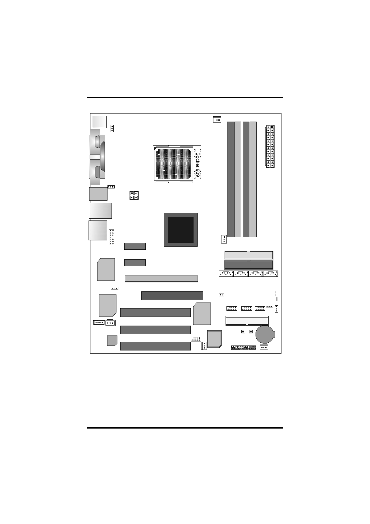
1.2 LAY OUT AND COMP ONENT S
JKBMS1
JCFAN1
JCOM1
(optional)
JKBMSV1
C
O
M
1
JPRNT1
C
JCOM2
O
M
2
DIMM 1
DIMM2
DIMM4
J1394_USB1
J1 394_ US BV 1
DIMM3
JATXPWR1
JCDIN1
JUSBLAN 1
EARPHONEJACK1
Giga L AN
IEEE 1394
JAUDIO2
J1394PWR1
Chip
JSPDIF_OUT
Code c
JATXPWR2
nForce4 /
nForce4
Ultra
PCI-EX x1
PEX1-2
PCI-EX x1
PEX1-1
PCI- EX16
XGP1
PC I1
PC I2
J1394A1
PC I3
Note: ■ represents the 1st pin.
Super I/ O
JSFAN2
BIOS
JNBFAN1
J
S
JCI1
A
T
A
1
JPANEL1
IDE2
IDE1
JSATA2 JSATA3 JS ATA 4
LED_D1
LED
LED
LED_ 5S B
JUSBV1
JUSB3JUSB2JUSB1
JCMOS1
FDD1
PWRSW RSTSW
BAT1
JSFAN1
DIMM
D2
3
User’s Manual
Page 6
Biostar T-Series TForce4/ TForce4 U
CHAPTER 2: HARDWARE INSTALLATION
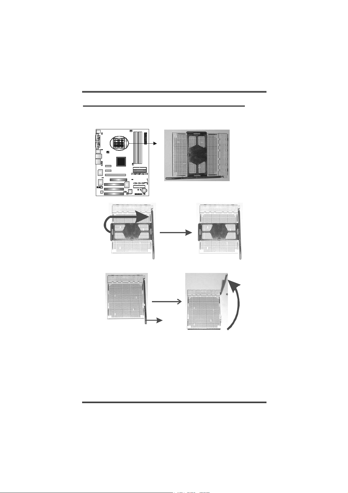
2.1 INSTALLING CENTRAL PRIOCESSING UNIT (CPU)
A. Central Processing Unit (CPU)
Step 1: Remove the socket protection cap.
Step 2: Pull the lever toward direction A from the socket and then raise
the lever up to a 90-degree angle.
90
A
Step 3: Look for the white triangle on socket, and the gold triangle on
CPU should point forwards this white triangle. The CPU will fit only in
the correct orientation.
4
User’s Manual
Page 7
Biostar T-Series TForce4/ TForce4 U
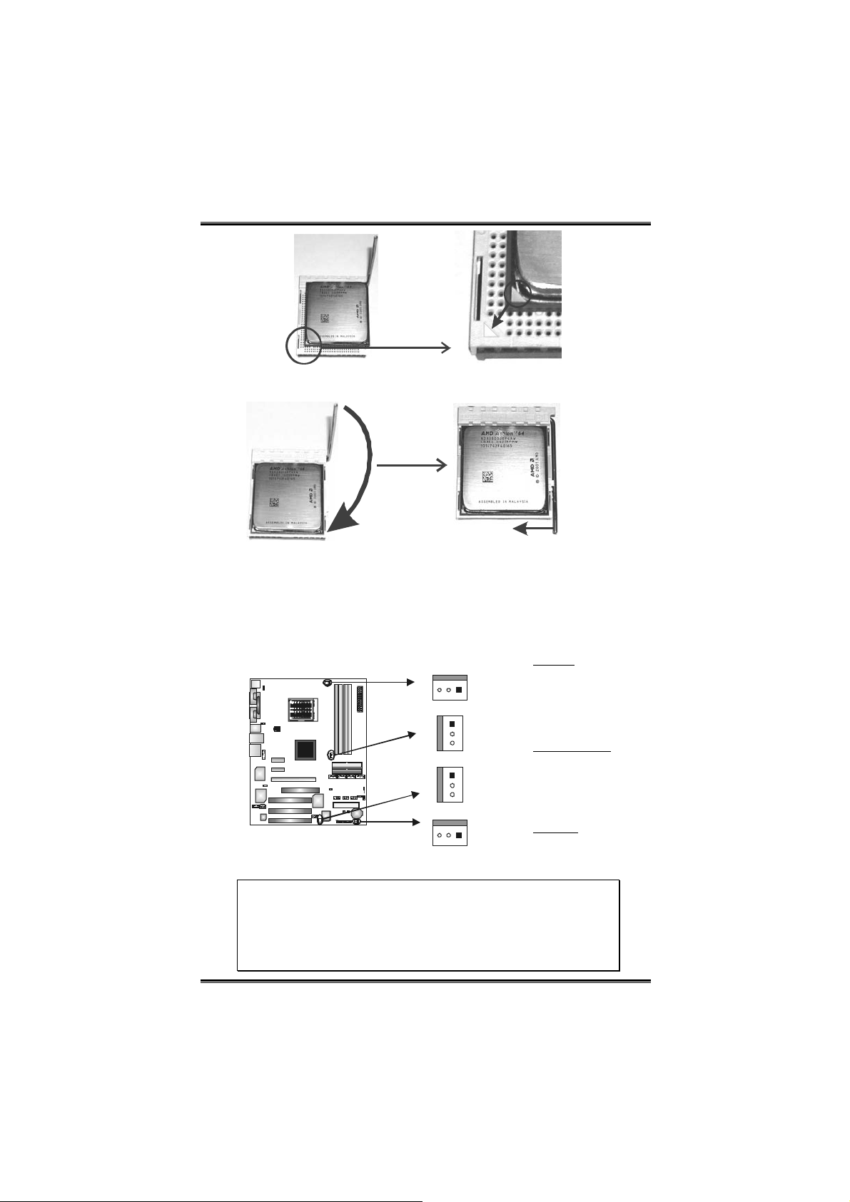
Step 4: Hold the CPU down firmly, and then close the lever toward
direct B to complete the installation.
B
Step 5: Put the CPU Fan on the CPU and buckle it. Connect the CPU
FAN power cable to the JCFAN1. This completes the installation.
B. About FAN Headers
CPU FAN Power Header: JCFAN1
System Fan Power Headers: JSFAN1/ JSFAN2
North Bridge Fan Po wer Header: JNBFAN1
JCFA N1:
Pin Assignment
JCFAN1
13
1
3
1
3
JNBFAN1
JSFAN2
JSFAN1
13
Note:
JCFAN1、 JSFAN1/JSFAN2 and JNBFAN1 reserve system cooling fan
with Smart Fan Control utilities. It supports 3 pin head connector. When
connecting with wires onto connectors, please note that the red wire is
the positive and should be connected to pin#2, and the black wire is
Ground and should be connected to GND.
1 Ground
2 Smart Fan
Control
FAN RPM r ate
3
sense
JSFAN1/JSFAN2
Pin Assignment
1 Ground
2 +12V
FAN RPM r ate
3
sense
JNBFAN1
1 Ground
2 +12V
N/A
3
5
User’s Manual
Page 8
Biostar T-Series TForce4/ TForce4 U
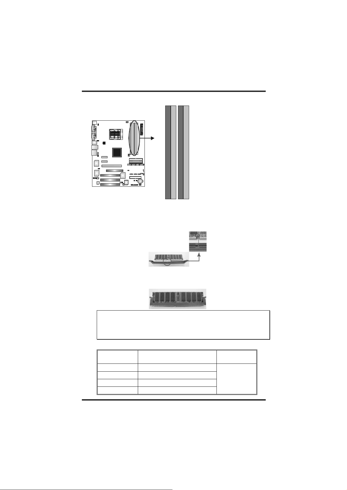
2.2 SYSTEM MEMORY
DIMM2
DIMM4
DIMM1
DIMM3
A. Memory Modules
1. Unlock a DIMM slot by pressing the retaining clips outward.
Align a DIMM on the slot such that the notch on the DIMM
matches the break on the slot.
2. Insert the DIMM vertically and firmly into the slot until the
retaining chip snaps back in place and the DIMM is properly
seated.
Notes:
To remove the DDR modules, push the ejector tabs at both sides
of the slot outward at the same time, and pull the modules out
vertically.
B. Memory Capacity
DIMM Socket
Location
DIMM1 128MB/256MB/512MB/1GB *1
DIMM2 128MB/256MB/512MB/1GB *1
DIMM3 128MB/256MB/512MB/1GB *1
DIMM4 128MB/256MB/512MB/1GB *1
DDR Module
6
Total Mem o ry
Size
Max is 4 GB.
User’s Manual
Page 9
Biostar T-Series TForce4/ TForce4 U
C. DDR Installation Notice
For AMD K8 939 CPU launched before Rev. E, please follow the
table below to install your DDR memory module, or the system
may not boot up or may not function properly. (Please refer to
Table 1 for CPU Revision)
“SS” represents Single Side DDR memory module.
“DS” represents Double Side DDR memory module.
Star sign “*” represents leave the DIMM socket empty.
DIMM1 SS/DS * SS/DS * SS/DS
DIMM2 * * SS/DS * SS/DS
DIMM3 * SS/DS * SS/DS SS/DS
DIMM4 * * * SS/DS SS/DS
D. Know your CPU version
AMD Athlon 64 Processor Ordering Part Number Example
ADA 3200 A E P 5 AP
Part Definition: AP = Rev C0
Table 1: AMD Athlon 64 Processor Part Definition
Part
Definition
AP Rev C0 BN Rev E4
AR Rev CG BP Rev E3
AS Rev CG BO Rev E3
AW Rev CG BY Rev E6
AX Rev CG BW Rev E6
AZ Rev CG
BI Rev D0
Revision Part
Definition
Revision
7
User’s Manual
Page 10
Biostar T-Series TForce4/ TForce4 U
2.3 PERIPHERALS
A. Card and I/O Slots:
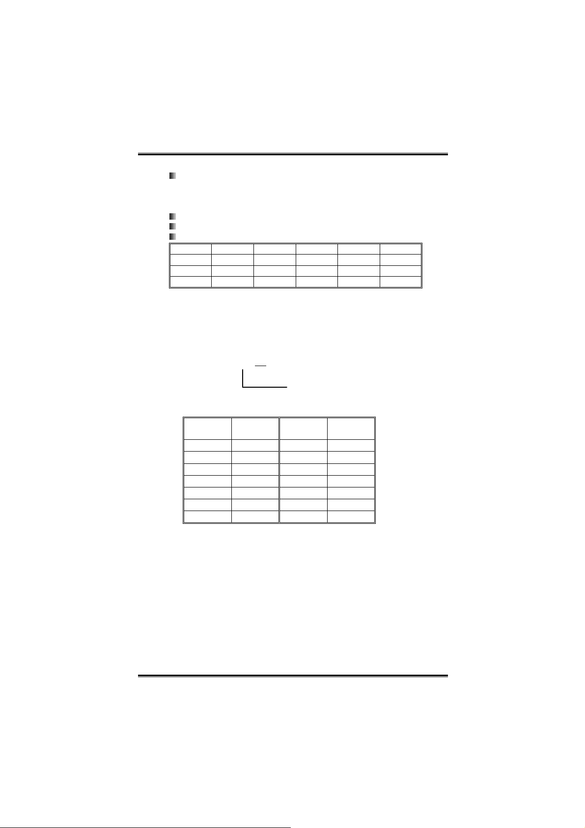
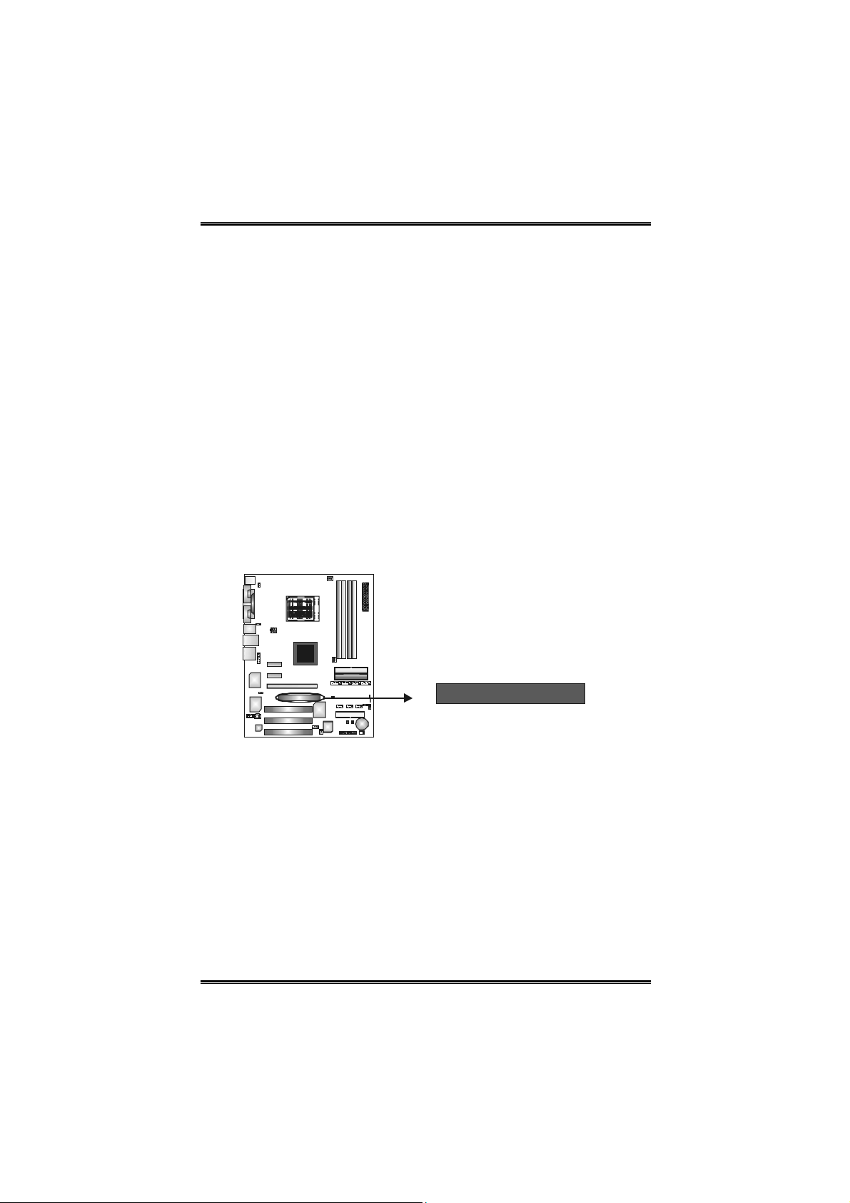
Floppy Disk Connector: FDD1
The motherboard provides a standard floppy disk connector that
supports 360K, 720K, 1.2M, 1.44M and 2.88M floppy disk types.
This connector supports the provided floppy drive ribbon cables.
2
1
34
33
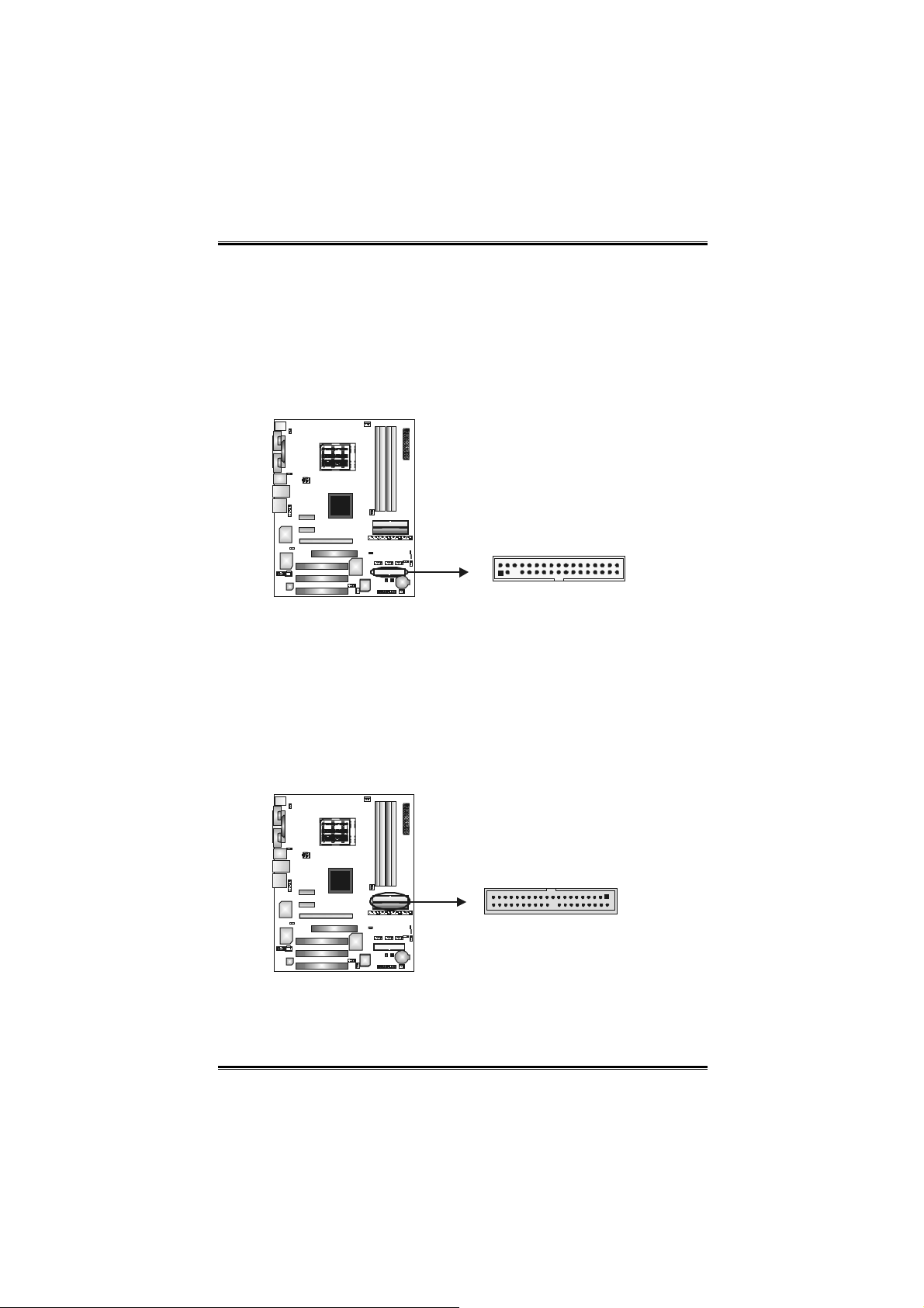
Hard Disk Connectors: IDE1/IDE2
The motherboard has two 32-bit Enhanced PCI IDE Controllers that
provide PIO Mode 0~5, Bus Master, and Ultra DMA 33/66/100/133
functionality. It has two HDD connectors IDE1 (primary) and IDE2
(secondary). The IDE connectors can connect a master and a slave
drive, so you can connect up to four hard disk drives. The first hard
drive should always be connected to IDE1.
IDE2
39
40
1
2
IDE1
8
User’s Manual
Page 11
Biostar T-Series TForce4/ TForce4 U
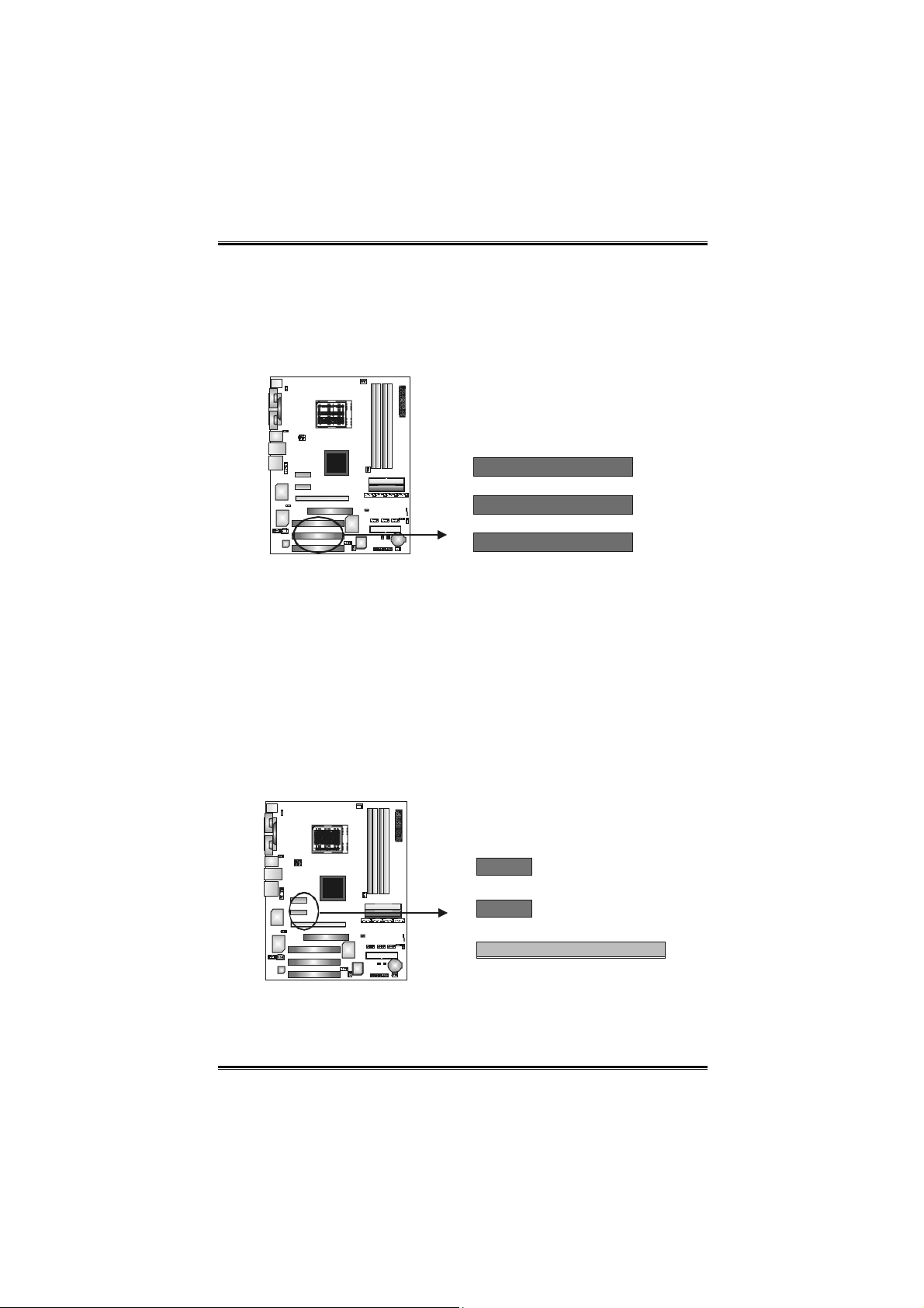
Peripheral Component Interconnect Slots: PCI1~PCI3
This motherboard is equipped with 3 standard PCI slots. PCI stands
for Peripheral Component Interconnect, and it is a bus standard for
expansion cards. This PCI slot is designated as 32 bits.
PCI1
PCI2
PCI3
PCI-Express Slots: PCI-EX16/ PEX1_2/ PEX1_1
PCI-EX16:
PCI Express 1.0a compliant.
Maximum bandwidth is up to 4GB/s per direction.
PEX1_2/ PEX1_1:
PCI Express 1.0a compliant.
Maximum bandwidth is up to 250MB/s per direction.
PCI-EXx1
PEX1-2
PCI-EXx1
PEX1-1
PCI-EX16
9
User’s Manual
Page 12
Biostar T-Series TForce4/ TForce4 U
Xtreme Graphics Port Slot: XGP1
This XGP (Extreme Graphics Port) slot is a special design that only
supports compatible AGP VGA cards.
To install the system with an add-on AGP VGA card, please make
sure to install the driver of add-on AGP VGA card before onboard
VGA driver installation. If the onboard VGA driver has already been
installed before you install the add-on AGP VGA card, the system
will automatically set the onboard VGA as the pri mary graphics
adapter.
For the onboard VGA driver can’t be removed completely, and to
solve this problem, please follow the steps below,
Disable onboard VGA utility under the operating system, and reboot
PC. After PC restarts, the system will automatically set the AGP
VGA card as the graphics adapter.
Or, re-install your operating system to ensure the AGP VGA card
function can be used.
Note:
Please go to “http://www.biostar.com.tw” for more detailed
information about XGP compatible AGP cards.
10
XGP1
User’s Manual
Page 13
Biostar T-Series TForce4/ TForce4 U
B. Connectors and Headers:
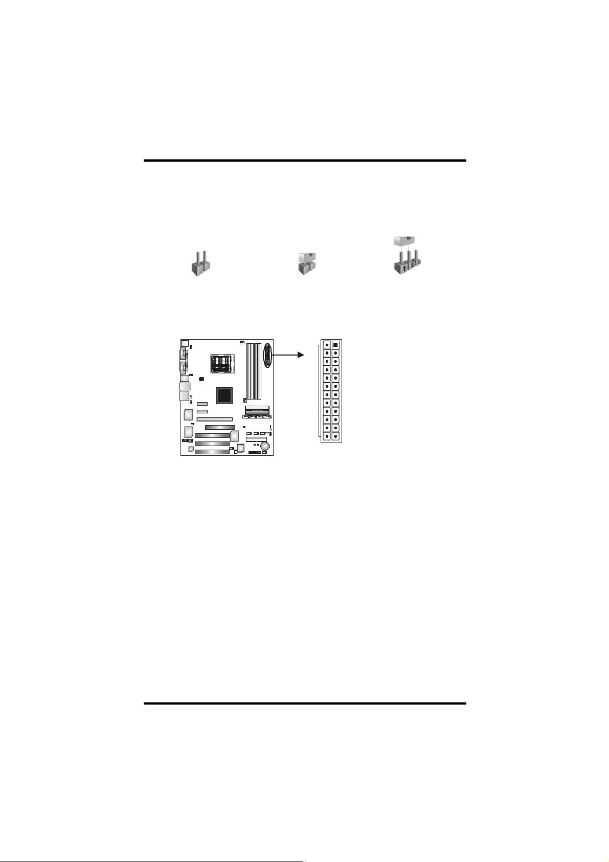
How to setup Jumpers
The illustration shows how to set up jumpers. When the jumper cap
is placed on pins, the jumper is “closed”, if not, that means the
jumper is “open”.
Pin opened Pin closed Pin1-2 closed
ATX Power Source Connector: JATXPWR1
JAT XPWR1 allows user to connect 24-pin power connector on the
AT X power supply.
113
1224
Pin Assignment Pin Assignment
13 +3.3V 1 +3.3V
14 -12V 2 +3.3V
15 Gro und 3 Gro und
16 PS_ON 4 +5V
17 Gro und 5 Gro und
18 Ground 6 +5V
19 Gro und 7 Gro und
20 NC 8 PW_OK
21 +5V 9 Standb y Voltage+5V
22 +5V 10 +12V
23 +5V 11 +12V
24 Ground 12 +3.3V
11
User’s Manual
Page 14
Biostar T-Series TForce4/ TForce4 U
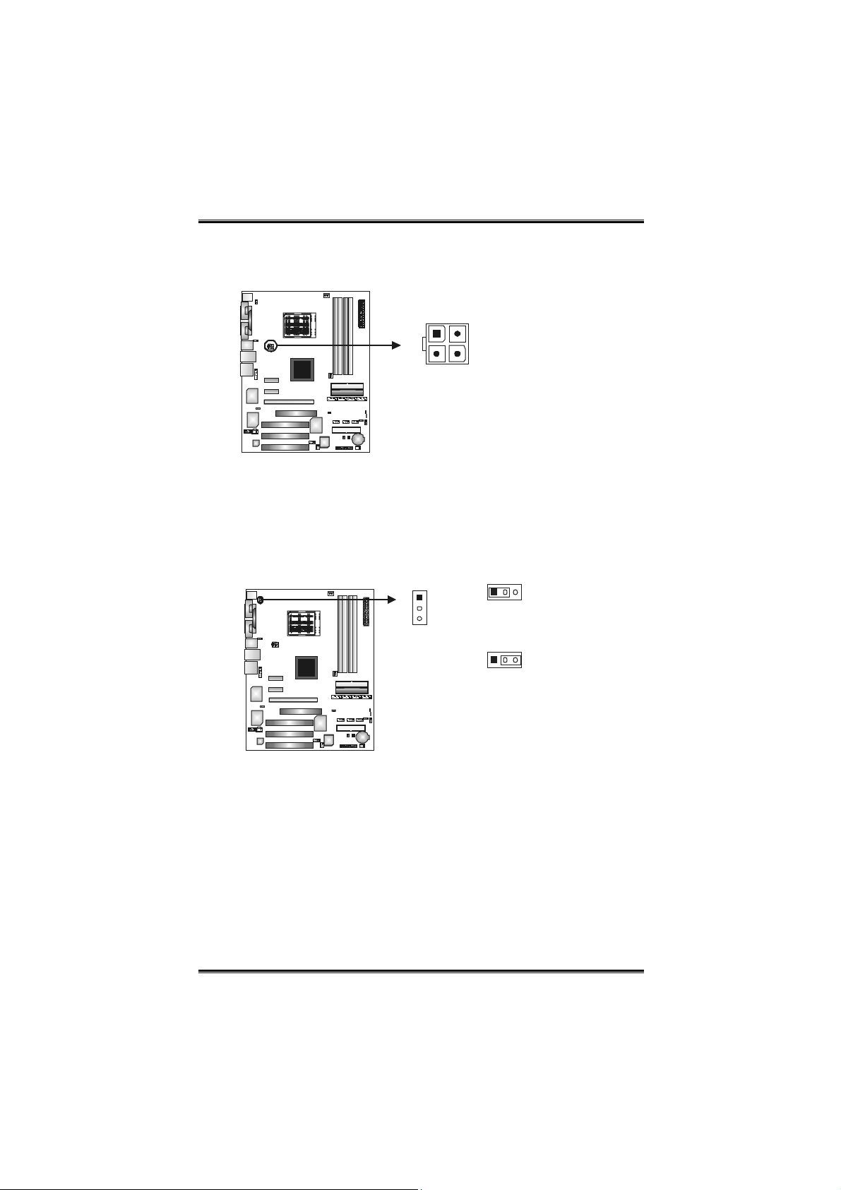
ATX Power Source Connector: JATXPWR2
By connecting JAT XPWR2, it will provide +12V to CPU power
circuit.
12
34
Pin
Assignment
1 +12V
2 +12V
3 Gro und
4 Gro und
Power Source Header for PS/2 Keyboard/Mouse: JKBMSV1
Pin 1-2 Close: +5V for PS/2 keyboard and mouse.
Pin 2-3 Close: PS/2 keyboard and mouse are powered with +5V
(Factory default setting)
standby voltage.
1
3
13
Pin 1-2 close
(Default)
13
Pin 2-3 close
Note: In order to support
this function “Power-on
syste m via keyboard and
mouse,” JKBMSV1
jumper cap should be
placed on Pin 2-3.
12
User’s Manual
Page 15
Biostar T-Series TForce4/ TForce4 U
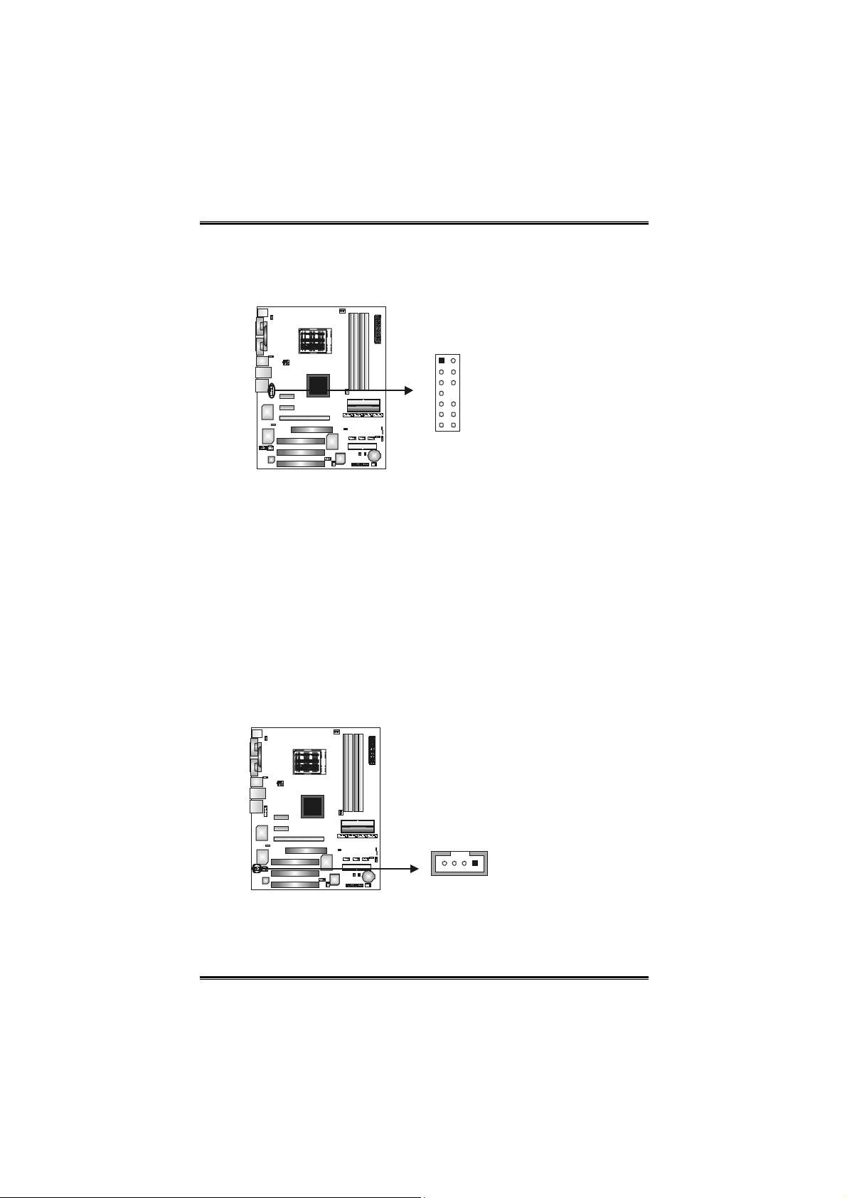
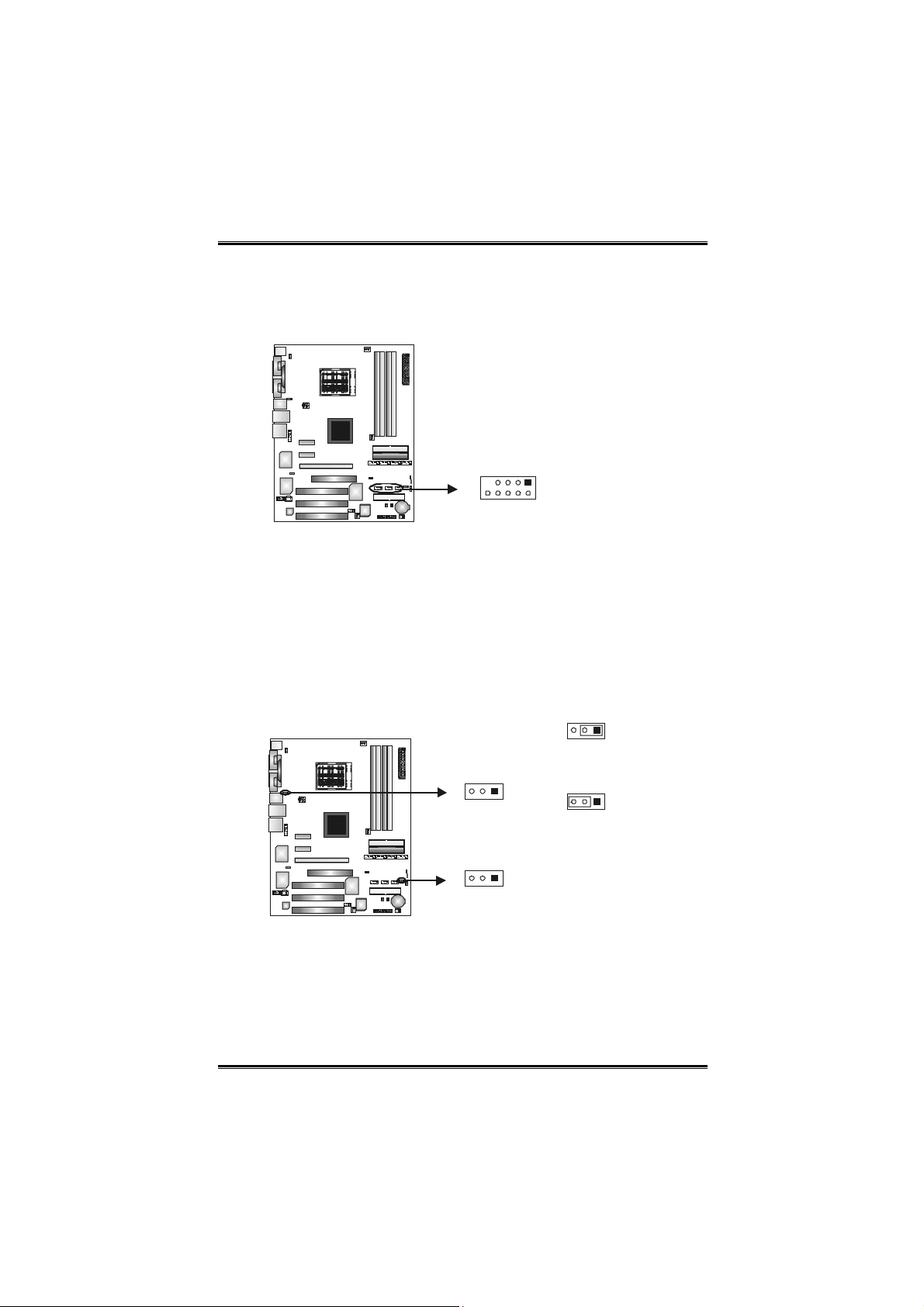
Front Panel Audio-out Header: JAUDIO2
This connector will allow user to connect with the front audio output
headers on the PC case. It will disable the output on back panel
audio connectors.
12
13 14
Pin Assignment Pin Assignment
1
Mic in/ce nte r
3
Mic power/Bass
Right li ne o ut/
5
Speaker out Right
7
Reserved
Left li ne o ut/
9
Speaker out Left
Right li ne i n/
11
Rear speaker Right
Left li ne i n/
13
Rear speaker Left
2
Gro und
4
Audio power
Right li ne o ut/
6
Speaker out Right
8
Key
Left li ne o ut/
10
Speaker out Left
Right li ne i n/
12
Rear speaker Right
Left li ne i n/
14
Rear speaker Left
CD-ROM Audio-in Connector: JCDIN1
This connector allows user to connect the audio source from a
variety of devices, like CD-ROM, DVD-ROM, PCI sound card, PCI
TV tuner card etc.
Pin
Assignment
1 Left channel
input
2 Gro und
3 Gro und
4 Right channel
input
14
13
User’s Manual
Page 16
Biostar T-Series TForce4/ TForce4 U
Headers for USB Ports at Front Panel: JUSB1~JUSB3
This connector allows user to connect additional USB cables at PC
front panel, and also can be connected with internal USB devices,
like USB card reader.
Pin
Assignment
1
+5V (fused)
2
+5V (fused)
3
USB-
4
USB-
5
6
7
8
9
10
USB+
USB+
Gro und
Gro und
Key
NC
JUSB1 JUSB2 JUSB3
9
10
1
2
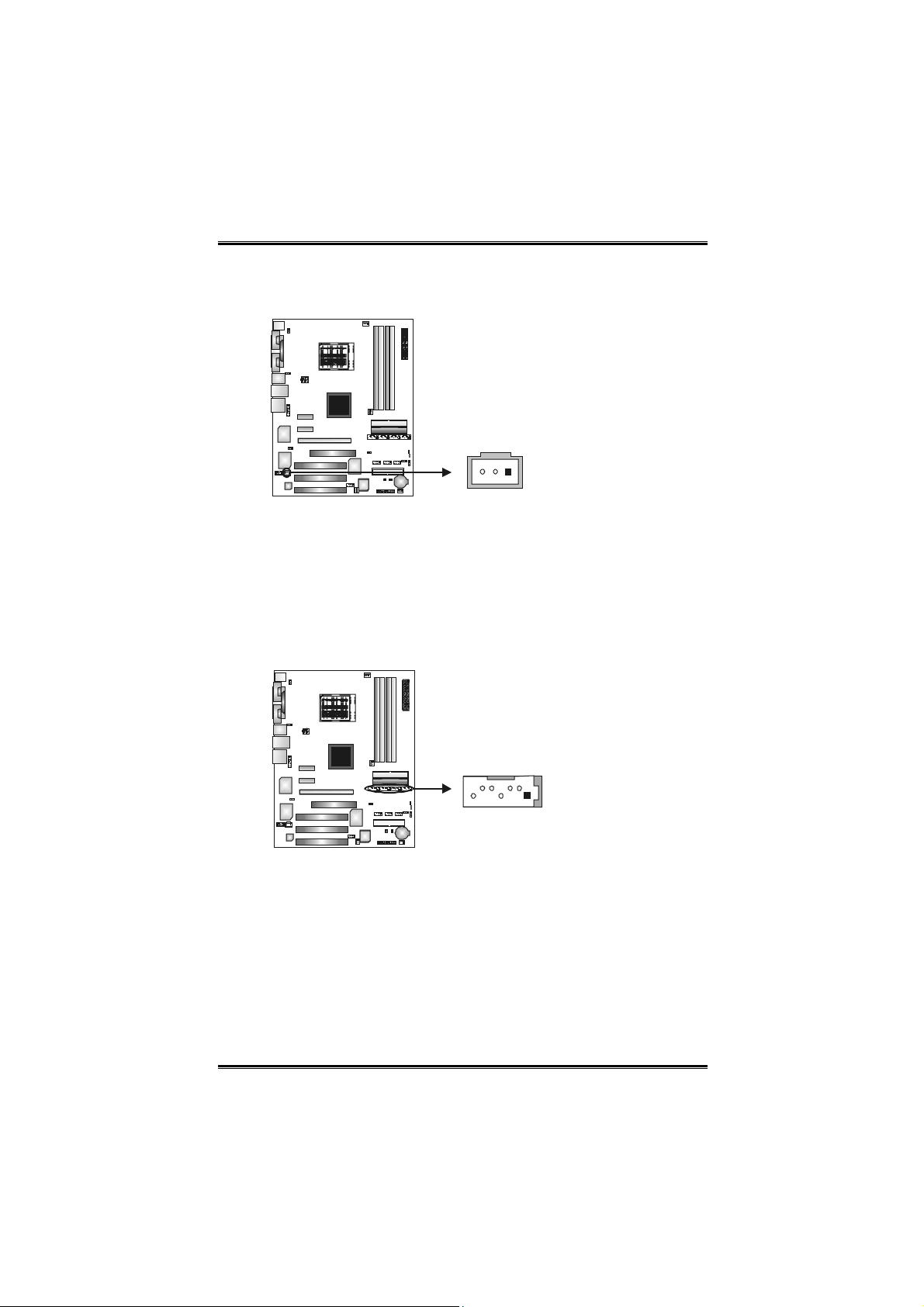
Power Source Headers for USB Ports: J1394_USBV1/JUSBV1
Pin 1-2 Close:
J1394_USBV1: +5V for USB ports at J1394_USB1 and JUSBLAN1.
JUSBV1: +5V for front USB headers (JUSB1/JUSB2/JUSB3).
Pin 2-3 Close:
J1394_USBV1: USB ports at J1394_USB1 and JUSBLAN1 are
JUSBV1: Front USB headers (JUSB1/JUSB2/JUSB3) are powered
powered with +5V standby voltage.
with +5V standby voltage.
Pin 1-2 close
(Default)
3
J1394_USBV1
JUSBV1
Pin 2-3 close
Note: In order to support
this function “Power-on
syste m via USB device,”
“J1394_USBV1/JUSBV1”
jumper cap should be
placed on Pin 2-3
individually.
13
1
14
User’s Manual
Page 17
Biostar T-Series TForce4/ TForce4 U
Digital Audio-out Connector: JSPDIF_OUT
This connector allows users to connect the PCI bracket SPDIF
output header.
Pin
Assignment
1 +5V
2 SPDIF OUT
3 Gro und
13
Serial ATA Connectors: JSATA1~JSATA4
The motherboard has an SATA Controller in nForce4 CK8-04 and
CK8-04 Ultra with 4 channels SATA interface, it satisfies the SATA
1.0 with transfer rate of 1.5 Gb/s and SATA 2.0 spec with transfer
rate of 3.0 Gb/s.
Pin
Assignment
1 Gro und
2 TX+
JSATA 1 J SATA2 JSATA3 J SATA4
147
3 TX4 Gro und
5 RX6 RX+
7 Gro und
15
User’s Manual
Page 18
Biostar T-Series TForce4/ TForce4 U
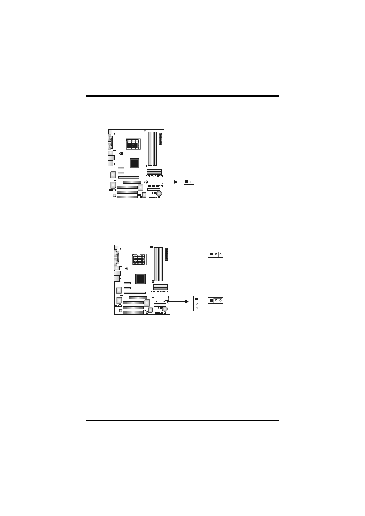
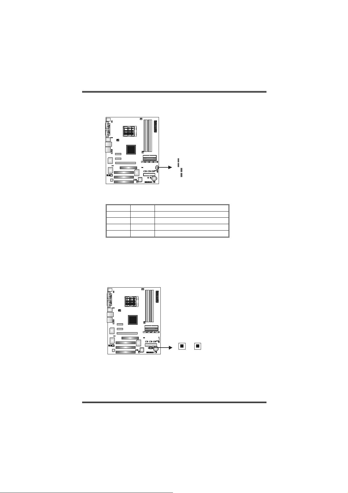
Case Open Header: JCI1
This connector allows system to monitor PC case open status. If the
signal has been triggered, it will record to the CMOS and show the
message on next boot-up.
Pin
12
Assignment
1 Case open signal
2 Gro und
Clear CMOS Header: JCMOS1
By placing the jumper on pin 2-3, it allows user to restore the BIOS
safe setting and the CMOS data, please carefully follow the
procedures to avoid damaging the motherboard.
13
Pin 1-2 close:
Normal Operation
(Default).
13
1
3
Pin 2-3 close:
Clear CMOS data.
Clear CMOS Procedures:※
1. Remove AC power line.
2. Set the jumper to “ Pin 2-3 close”.
3. Wait for five seconds.
4. Set the jumper to “ Pin 1-2 close”.1
5. Power on the AC.
6. Reset your desired password or clear the CMOS data.
16
User’s Manual
Page 19
Biostar T-Series TForce4/ TForce4 U
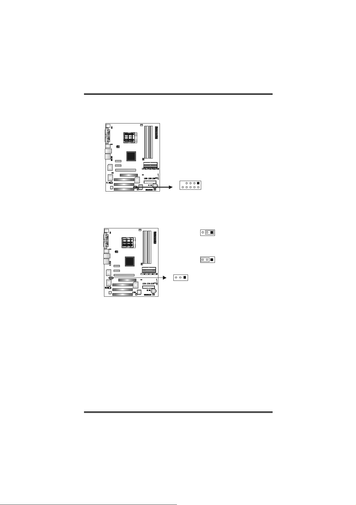
J1394A1: Header for 1394 Firewire Port at Front Panel
This header allows user to connect the digital image device, like DV,
D8, or V8, etc.
Pin
Assignment
1 A+
2 A-
3 Ground
4 Ground
5 B+
6 B-
1
9
2
10
7 +12V
8 +12V
9 Key
10 Ground
J1394PWR1: Power Source for 1394 Firewire Port
13
Pin 1-2 close
+3.3V for 1394 chipset (Default).
3
1
Pin 2-3 close
13
+3.3V SB for 1394 chipset.
17
User’s Manual
Page 20
Biostar T-Series TForce4/ TForce4 U
On-Board LED Indicators
There are 2 LED indicators on the motherboard to show system
status.
LED_D1
LED_D2
LED_DIMM
LED_5SB
LED_D1 and LED_D2:
These 2 LED indicate system power on diagnostics.
Please refer to the table below for different messages:
LED_D1 LED_D2 Message
ON ON Norma l
ON OFF Memory Error
OFF ON VGA Error
OFF OFF Abnormal: CPU / Chipset error.
LED_DIMM:
This LED indicates the voltage of memory is activated normally.
LED_5SB:
This LED indicates the system is ready for Power-on.
On-Board Buttons
There are 2 on-board buttons.
PWRSW RS TSW
PWRSW:
This is an on-board Power Switch button.
RSTSW:
This is an on-board Reset button.
18
User’s Manual
Page 21

Biostar T-Series TForce4/ TForce4 U
CHAPTER 3: NVIDIA RAID FUNCTIONS
3.1 OPERATION SYSTEM
Supports Windows XP Home/Professional Edition, and
Windows 2000 Professional.
3.2 RAID ARRAYS
NVRAID supports the following types of RAID arrays:
RAID 0: RAID 0 defines a disk striping scheme that improves
disk read and write times for many applications.
RAID 1: RAID 1 defines techniques for mirroring data.
RAID 0+1: RAID 0+1 combines the techniques used in RAID 0
and RAID 1.
Spanning (JBOD): JBOD provides a method for combining
drives of different sizes in to one large disk.
19
User’s Manual
Page 22
Biostar T-Series TForce4/ TForce4 U
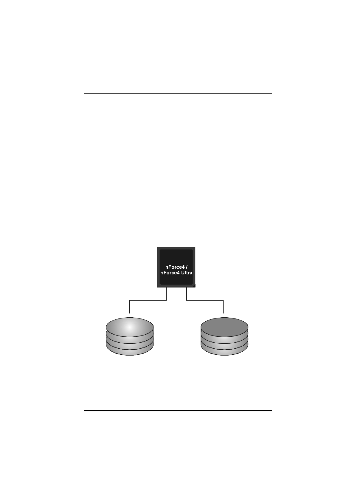
3.3 HOW RAID WORKS
RAID 0:
The controller “stripes” data across multiple drives in a RAID 0
array system. It breaks up a large file into smaller blocks and
performs disk reads and writes across multiple drives in parallel.
The size of each block is determined by the stripe size
parameter, which you set during the creation of the RAID set
based on the system environment. This technique reduces
overall disk access time and offers high bandwidth.
Featur es and Benefits
Drives: Minimum 1, and maximum is up to 6 or 8. Depending on
the platform.
Uses: Intended for non-critical data requiring high data
throughput, or any environment that does not require fault
tolerance.
Benefits: provides increased data throughput, especially for
large files. No capacity loss penalty for parity.
Drawbacks: Does not deliver any fault tolerance. If any drive in
the array fails, all data is lost.
Fault Tolerance: No.
Data 1
Data 3
Data 5
20
Data 2
Data 4
Data 6
User’s Manual
Page 23
Biostar T-Series TForce4/ TForce4 U
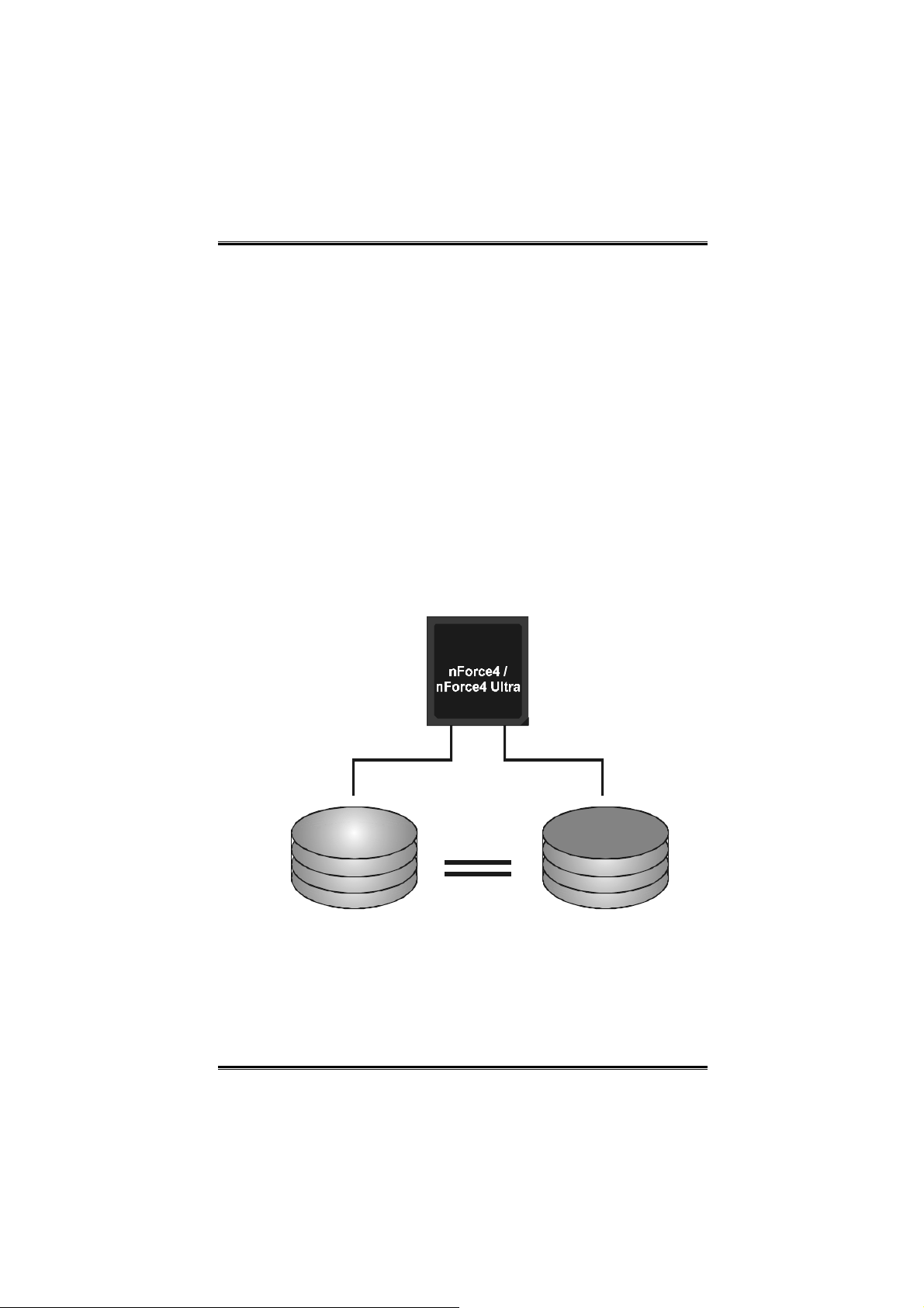
RAID 1:
Every read and write is actually carried out in parallel across 2
disk drives in a RAID 1 array system. The mirrored (backup)
copy of the data can reside on the same disk or on a second
redundant drive in the array. RAID 1 provides a hot-standby
copy of data if the active volume or drive is corrupted or
becomes unavailable because of a hardware failure.
RAID techniques can be applied for high-availability solutions,
or as a form of automatic backup that eliminates tedious
manual backups to more expensive and less reliable media.
Featur es and Benefits
Drives: Minimum 2, and maximum is 2.
Uses: RAID 1 is ideal for small databases or any other
application that requires fault tolerance and minimal capacity.
Benefits: Provides 100% data redundancy. Should one drive
fail, the controller switches to the other drive.
Drawbacks: Requires 2 drives for the storage space of one
drive. Performance is impaired during drive rebuilds.
Fault Tolerance: Yes.
Data 1
Data 2
Data 3
21
Data 1
Data 2
Data 3
User’s Manual
Page 24
Biostar T-Series TForce4/ TForce4 U
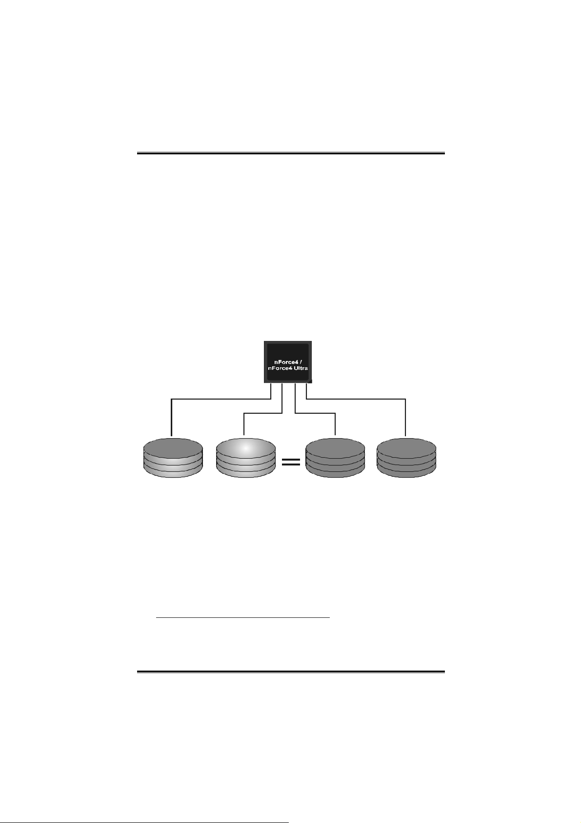
RAID 0+1:
RAID 0 drives can be mirrored using RAID 1 techniques.
Resulting in a RAID 0+1 solution for improved performance plus
resiliency.
Featur es and Benefits
- Drives: Minimum 4, and maximum is 6 or 8, depending on the
platform.
- Benefits: Optimizes for both fault tolerance and performance,
allowing for automatic redundancy. May be si multaneously
used with other RAID levels in an array, and allows for spare
disks.
- Drawbacks: Requires twice the available disk space for data
redundancy, the same as R AID level 1.
- Fault Tolerance: Yes.
Data 1
Data 3
Data 5
Data 2
Data 4
Data 6
Data 1
Data 3
Data 5
Data 2
Data 4
Data 6
※ For more detailed setup information, please refer to the Driver CD, or go to
http://www.nvidia.com/page/pg_20011106217193.html to download NVIDIA nForce
Tuto rial Flash.
22
User’s Manual
Page 25

Biostar T-Series TForce4/ TForce4 U
CHAPTER 4: OVERCLOCK QUICK GUIDE
4.1: T-POWER INTRODUCTION
Biostar T-Power is a whole new utility that is designed for
overclock users.
Based on many precise tests, Biostar Engineering Team (BET)
has developed this ultimate overclock engine to raise system
performance.
No matter whether under BIOS or Windows interface, T-Power
is able to present the best system state according to users’
overclock setting.
T-Power BIOS Features:
Overclocking Navigator Engine (O.N.E.)
CMOS Reloading Program (C.R.P.)
Memory Integration Test (M.I.T., under Overclock Navigator
Engine)
Integrated Flash Program (I.F.P.)
Smart Fan Function (under PC Health Status)
Self Recovery System (S.R.S)
T-Power Windows Feature:
Hardware Monitor
Overclock Engine
Smart Fan Function
Life Update
23
User’s Manual
Page 26
Biostar T-Series TForce4/ TForce4 U
4.2: T-POWER BIOS FEATURE
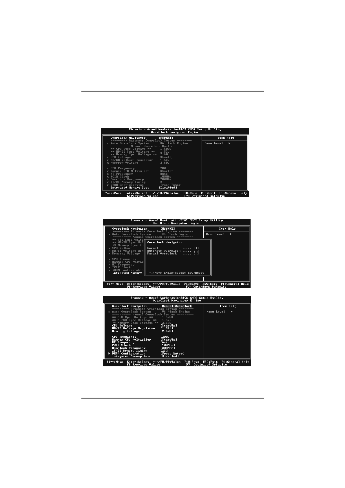
A. Overclocking Navigator Engine (O.N.E.):
ONE provides two powerful overclocking engines: MOS and
AOS for both Elite and Casual overclockers.
Manual Overclock System (M.O.S.)
MOS is designed for experienced overclock users.
It allows users to customize personal overclock settings.
24
User’s Manual
Page 27

Biostar T-Series TForce4/ TForce4 U
CPU Overclock Setting:
CPU Voltage :
This function will increase CPU stability when overclocking.
However, the CPU temperature will increase when CPU
voltage is increased.
Choices: T he range is from 1.2V to 1.725V, with a n interval of
0.0.25V.
CPU Frequency:
CPU Frequency is directly in proportion to system performance.
To maintain the system stability, CPU voltage needs to be
increased also when raising CPU frequency.
Choices: This range is from 200 to 450, with an interval of
1MHz.
Hammer CPU Multiplie r:
The MOS allows users to downgrade the CPU ratio when
overclocking.
Choices: The lower limit is x4 (800MHz). The upper limit is
decided by different CPU type. With an x1 (200MHz) interval.
Memory Overclock Setting:
Memory Voltage :
This function will increase memory stability when overclocking.
Choices: T he range is from 2.6V to 2.9V, with an int erval of
0.1V.
Me mc lock Fre q ue ncy :
To get better system performance, someti mes downgrading the
memory frequency is necessary when CPU frequency is
adjusted over the upper limit.
Choices: 100, 133, 166, 200, 216, 233, 250 (MHz).
PCI-Express Overclock Setting:
PCIE Clock:
It helps to increase VGA card perfor mance.
Choices: T he range is from 100 to 145, with an interval of
1MHz.
Chipset Overclock Setting:
NB/SB Voltage Regulator:
This function will increase chipset stability when overclocking.
Choices: 1.52V, 1.60 V, 1.68V, 1.76V.
HT Fre que ncy :
We recommend users to set this item at “x4” when
overclocking.
Choices: x1, x2, x3, x4, x5, Auto.
25
User’s Manual
Page 28
Biostar T-Series TForce4/ TForce4 U
Notice: According to tests that have been done; AMD Athlon XP 3000+ CPU is
the best CPU type for overclock function.
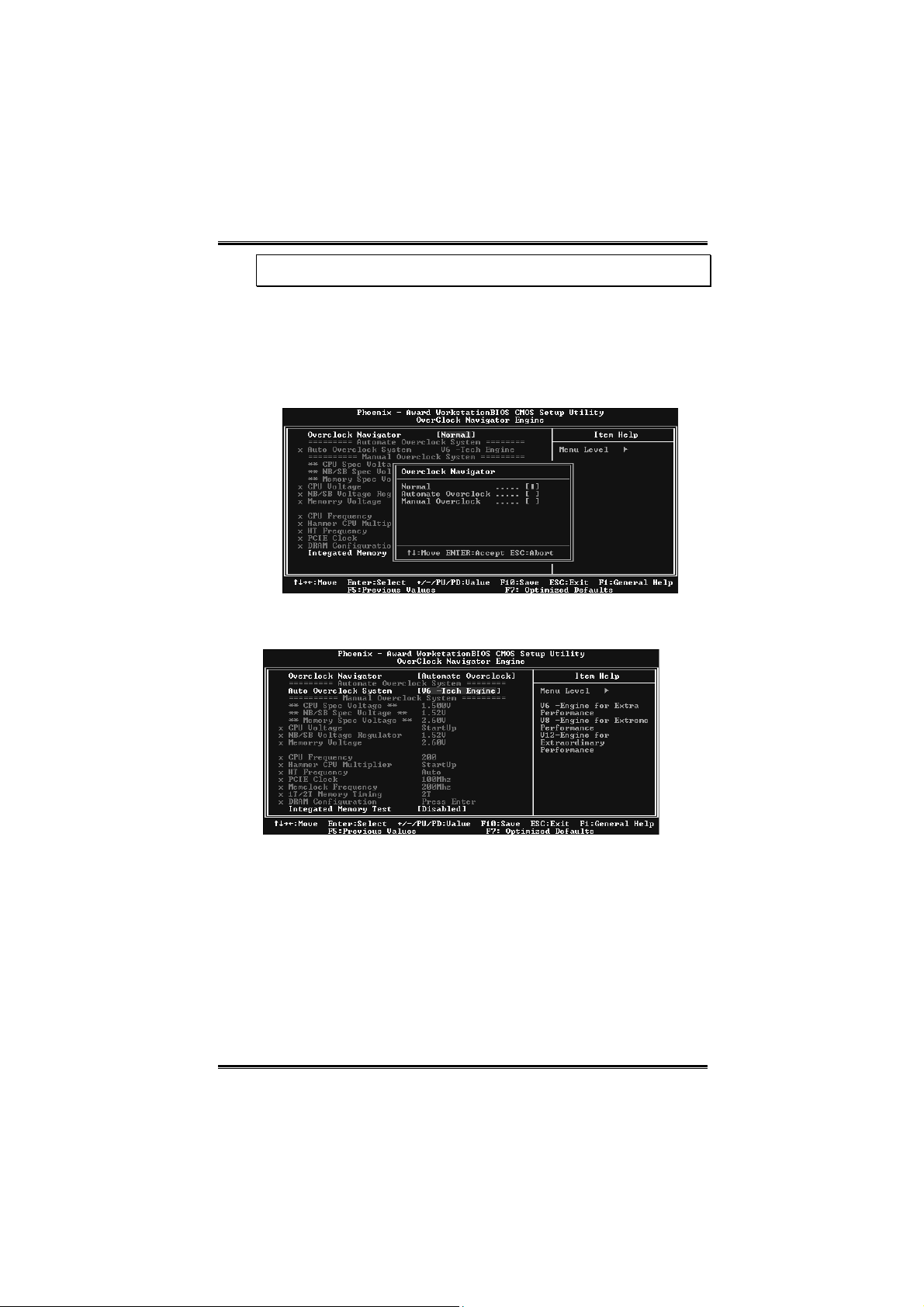
Automatic Overclock System (A.O.S.)
For beginners in overclock field, BET had developed an easy,
fast, and powerful feature to increase the system performance,
named A.O.S.
Based on many tests and experiments, A.O.S. provides 3 ideal
overclock configurations that are able to raise the system
performance in a single step.
V6 Tech Engine:
This setting will raise about 10%~15% of whole system
performance.
26
User’s Manual
Page 29
Biostar T-Series TForce4/ TForce4 U
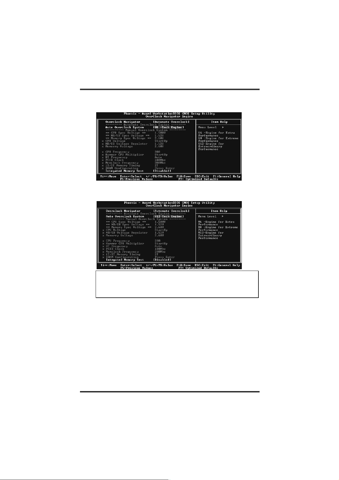
V8 Tech Engine:
This setting will raise about 15%~25% of whole system
performance.
V12 Tech Engine:
This setting will raise about 25%~30% of whole system
performance.
Notices:
1. Not all types of AMD CPU perform above overclock setting ideally; the difference
will be based on the selected CPU model.
2. From BET experiments, the Atholon64 FX CPU is not suitable for this A.O.S.
feature.
27
User’s Manual
Page 30
Biostar T-Series TForce4/ TForce4 U
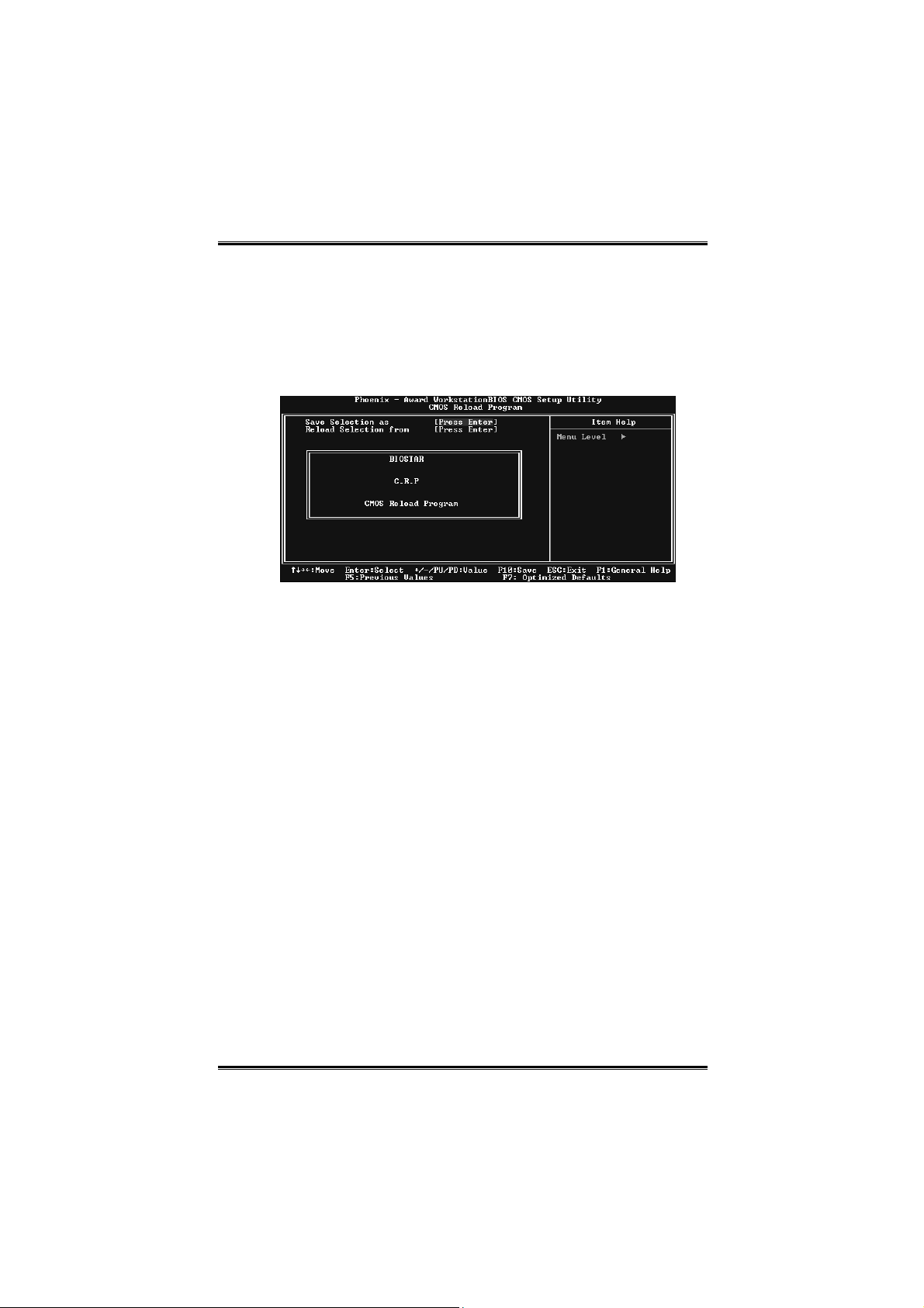
B. CMOS Reloading Program (C.R.P.):
It allows users to save different CMOS settings into BIOS-ROM.
Users are able to reload any saved CMOS setting for customizing
system configurations.
Moreover, users are able to save an ideal overclock setting during
overclock operation.
There are 50 sets of record addresses in total, and users are able to
name the CMOS data according to personal preference.
28
User’s Manual
Page 31

Biostar T-Series TForce4/ TForce4 U
C. Memory Integration Test (M.I.T.):
This function is under “Overclocking Navigator Engine” item.
MIT allows users to test memory compatibilities, and no extra
devices or software are needed.
Step 1:
The default setting under this item is “Disabled”; the condition
parameter should be changed to “Enable” to proceed this test.
↓
Step 2:
Save and Exit from CMOS setup and reboot the system to activate
this test.
Run this test for 5 minutes (minimum) to ensure the memory
stability.
Step 3:
When the process is done, change the setting back from “ Enable” to
“Disable” to complete the test.
29
User’s Manual
Page 32

Biostar T-Series TForce4/ TForce4 U
D. Self Recovery System (S.R.S.):
This function can’t be seen under T-Power BIOS setup; and is
always on whenever the system starts up.
However, it can prevent system hang-up due to inappropriate
overclock actions.
When the system hangs up, S.R.S. will automatically log in the
default BIOS setting, and all overclock settings will be re-configured.
E. Integrated Flash Program (I.F.P.):
IFP is a safe and quick way to upgrade BIOS.
By pressing “Enter” key three times, and the upgrading process will
be completed easily.
F. Smart Fan Function:
Smart Fan Function is under “PC Health Status”.
This is a brilliant feature to control CPU Temperature vs. Fan speed.
When enabling Smart Fan function, Fan speed is controlled
automatically by CPU temperature.
This function will protect CPU from overheat problem and maintain
the system temperature at a safe level.
↓
CPU Fan Off <℃>:
If the CPU temperature is lower than the set value, the CPU
fan will turn off. The range is from 0℃~127℃, with an interval
of 1℃.
Choices: 16℃ (default).
30
User’s Manual
Page 33

Biostar T-Series TForce4/ TForce4 U
CPU Fan Start <℃>
The CPU fan starts to work when CPU temperature arrives to
this set value. The range is from 0℃~127℃, with an interval of
1℃.
Choices: 32℃ (default).
CPU Fan Full speed <℃ >
When CPU temperature arrives to the set value, the CPU fan
will work under Full Speed. The range is from 0℃~127℃, with
an interval of 1℃.
Choices: 52℃ (default).
Start PWM Value
When CPU temperature arrives to the set value, the CPU fan
will work under Smart Fan Function mode. The range is from
0~127, with an interval of 1.
Choices: 32 (default).
Slope PWM
Choices: 1 PWM Value/℃ (default), 2 PWM Value/℃, 4 PWM
Value/℃, 8 PWM Value/℃, 16 PWM Value/℃, 32 PWM
Value/℃, 64PWM Value/℃.
S1: CPU temperature is 60℃, and PWM value is 1 PWM /℃.
S2: CPU temperature is 60℃, and PWM value is 2 PWM /℃.
S3: CPU temperature is 60℃, and PWM value is 3 PWM /℃.
Increasing the value of slope PWM will raise the speed of CPU
fan.
As in above diagram, when the CPU temperature reaches 60℃,
the CPU fan speed for 3 PWM/℃ is higher than 1 PWM/℃
(S1<S2<S3).
31
User’s Manual
Page 34

Biostar T-Series TForce4/ TForce4 U
4.3 T-POWER WINDOWS FEATURE
A.Hardware Monitor:
T-Power Hardware monitor allows users to monitor system
voltage, temperature and fan speed accordingly.
Additionally, a rescue action will be taken by the program
automatically while the system faces an abnormal condition.
The program will trigger an alarm or shut down the system
when unpredictable errors occur.
All the monitoring items are illustrated by a waveform diagram.
Hardware Monitor Toolbar
i. Start-up Setting
Click on this item to run Hardware Monitor Program when the
Windows starts-up.
ii. Dialogue-Box Setting
Click on this item to pop-up warning dialogue-box when PC
system is abnormal.
iii. Exit
Click on this item to exit Hardware Monitor Program.
iv. Hide
Click on this item to hide this program in system tray. When
hiding the program, there will be a check icon in the system
tray.
32
User’s Manual
Page 35

Biostar T-Series TForce4/ TForce4 U
CPU Temperature
This column configures the CPU temperature. There is a waveform
to represent the status of CPU temperature.
By adjusting , users can easily configure the upper limit of CPU
temperature for system operating.
In this diagram, the white line represents the upper limit which
user-set for CPU temperature and the green line shows present
CPU temperature.
If the CPU temperature is higher than the upper limit, the status line
color will change from green to red, and a warning sound will alert
you. Also, the system tray icon
would change to .
FAN Speed
By adjusting , users can easily configure the lower limit of the
fan speed.
In this diagram, the green line shows present CPU Fan speed, and
the yellow line shows System Fan speed (if any).
If any one of the fans speeds is lower than the set value, the status
line will change into a red warning line, and the program will trigger
an alarm system automatically. Also, the system tray icon
would change to
.
33
User’s Manual
Page 36

Biostar T-Series TForce4/ TForce4 U
CPU/Battery Voltage
i. VCore
This item displays the CPU voltage, represented by a light blue
line.
Users can set the upper and lower limit by adjusting
monitor the CPU operating voltage.
If CPU voltage is higher or lower than the set value, the status
line will change into a red warning line, and a warning sound
will alert you. Also, the system tray icon
ii. VBAT
This item displays the CMOS battery voltage, represented by a
light green line.
Users can set the upper and lower limit by adjusting
monitor the status of battery voltage.
If battery voltage is higher or lower than the set value, the
status line will change to a red warning line, and a warning
sound will alert you. Also, the system tray icon
to
.
will change to .
Reference data
This column represents the status of power supply voltage and
cannot be adjusted, it is only for present status reference.
to
to
will change
34
User’s Manual
Page 37

Biostar T-Series TForce4/ TForce4 U
B. Overclocking Configurations
This diagram is designed for T-series
Overclocking utility. Friendly interface and solid
overclock features are the major concept of this
utility.
Graphic 1 will appear when activating this utility.
Graphic 2
By adjusting the overclocking
features in 4 sub-screens, users can
tune the system performance to an
optimal level.
Graphic 1
A. Clicking on “Biostar” will lead you to the
Biostar Homepage.
B. This column shows the CPU speed
information.
C. Click on this button and the utility will
pop-up 4 sub-screens (Please refers to
Graphic 3).
D. Click on this button to minimize this
program to taskbar.
E. This column shows present CPU speed
and overclocking percentage.
F. Clicking on this button will make the
program start up as soon as the
Windows starts up.
G. Click on this button to exit this overclock
utility.
H. Click on this button to reset all the
overclock features to default setting.
Graphic 3
35
User’s Manual
Page 38

Biostar T-Series TForce4/ TForce4 U
CPU Overclocking Settings:
By adj ust i ng can configure three items
for CPU overclocking.
A. CPU Frequency
Range: 133MHz~450MHz.
Inter val: 1MHz.
B. CPU Ratio
Range: 4~25.
Inter val: 1.
C. CPU Voltage
Range: 1.175V~1.725V.
Interval: 0.025V.
Memory Overclocking Settings:
By adj ust i ng can configure two items
for Memory overclocking.
A. Memory Clock Frequency
Choices: 100, 133, 166, 200, 233, 250.
B. M emory Voltage
Range: 2.5V~2.8V.
Inter val: 0.1V.
AGP/PCI-Express Overclocking Setting:
By adj ust i ng can configure VGA card
overclocking. And this function helps to
increase VGA card performance.
Range: 100MHz~150MHz.
Inter val: 1MHz.
36
User’s Manual
Page 39

Biostar T-Series TForce4/ TForce4 U
PCI Overclocking Setting:
This diagram shows present PCI working
status and helps to monitor PCI
peripherals working status.
This item cannot be adjusted.
37
User’s Manual
Page 40

Biostar T-Series TForce4/ TForce4 U
C. Smart Fan Function
When Smart Fan Function is activated, screens will pop-up to
illustrate the fan speed information.
i. CPU Temperature:
Show current CPU temperature.
ii. CPU Fan speed:
Show current CPU Fan speed.
iii. System Fan speed:
Show current system Fan speed.
iv. Calibrate:
When changing CPU Fan or System Fan, click on this
button to re-calibrate the Fan speed.
Note:
1. When Smart Fa n F uncti o n ac tivates for t he first ti me, this calibrate
function would auto-run to get upper and lower limitation of CPU Fan and
System Fan.
2. When calibrating process is done, the calibrating window will auto-close,
and the main screen will show new fan speed data.
38
User’s Manual
Page 41

Biostar T-Series TForce4/ TForce4 U
v. Auto:
If the green indicator is lit up, the Smart Fan Function
is “On” (Default Setting).
Click on this button again to close Smart Fan Function,
and a screen as below would pop-up.
There will be pulling-meter besides the CPU Fan and
System Fan, the CPU Fan and the System Fan speed
can be adjusted by adjusting the Cursor Up or Down.
vi. Program Tool Bar:
z About:
Click on this button to get program-related
information.
z Minimize:
Click on this button to minimize the program to
system tray
z Exit:
Click on this button to exit this program.
39
User’s Manual
Page 42

Biostar T-Series TForce4/ TForce4 U
D. Live Update
When Live Update program is activated, a screen will pop up to
illustrate BIOS related information.
i. Link to Internet:
Click on this button will link to Biostar website and
BIOS file will be downloaded.
ii. Update BIOS:
Click on this button to run BIOS flashing process, and
it’s easy and safe.
iii. Backup BIOS:
Click on this button, and BIOS file will be saved into
the user-selected folder.
iv. Clear CMOS:
Click on this item will clear the CMOS Data. When
carrying this job, the previous CMOS data would be
cleared and returned to default setting.
40
User’s Manual
Page 43

Biostar T-Series TForce4/ TForce4 U
CHAPTER 5: USEFUL HELP
5.1 DRIVER INST ALLAT IO N NOTE
After you installed your operating system, please insert the
Fully Setup Driver CD into your optical drive and install the
driver for better system performance.
You will see the following window after you insert the CD
The setup guide will auto detect your motherboard and
operating system.
Note:
If this window didn’t show up after you insert the Driver CD, please use file
browser to locate and execute the file SETUP.EXE under your optical drive.
Driver Installation
To install the driver, please click on the Driver icon. The setup
guide will list the compatible driver for your motherboard and
operating system. Click on each device driver to launch the
installation program.
Software Installation
To install the software, please click on the Software icon. The
setup guide will list the software available for your system, click
on each software title to launch the installation program.
41
User’s Manual
Page 44

Biostar T-Series TForce4/ TForce4 U
Manual
Aside from the paperback manual, we also provide manual in
the Driver CD. Click on the Manual icon to browse for available
manual.
Note:
You will need Acrobat Reader to open the manual file. Please download the
latest version of Acrobat Reader software from
http://www.adobe.com/products/acrobat/readstep2.html
5.2 AWARD BIOS BEEP CODE
Beep Sound Meaning
One long beep followed by two
short beeps
High-low siren sound
One Short beep when system
boots-up
Long beeps every other second No DRAM detected or installed
Video card not found or video card
memory bad
CPU overheated
System will shut down
automatically
No error found during POST
42
User’s Manual
Page 45

Biostar T-Series TForce4/ TForce4 U
5.3 EXTRA INFORMATION
A. BIOS Update
After you fail to update BIOS or BIOS is invaded by a virus, the
Boot-Block function will help to restore BIOS. If the following
message is shown after boot-up of the system, it means the
BIOS contents are corrupted.
In this case, please follow the procedure below to restore the
BIOS:
1. Make a bootable floppy disk.
2. Download the Flash Utility “AWDFLASH.exe” from the
Biostar website: www.biostar.com.tw
3. Confirm motherboard model and downl7oad the
respective BIOS from Biostar website.
4. Copy “AWDFLASH.exe” and respective BIOS onto
floppy disk.
5. Insert the bootable disk into floppy drive and press
Enter.
6. System will boot-up to DOS prompt.
7. Type “Awdflash xxxx.bf/sn/py/r” in DOS prompt.
8. System will update BIOS automatically and restart.
9. The BIOS has been recovered a nd will work properly.
43
User’s Manual
Page 46

Biostar T-Series TForce4/ TForce4 U
B. CPU Overheated
If the system shuts down automatically after power on of
system for a few seconds that means the CPU protection
function has been activated.
When the CPU is over heated, the motherboard will shutdown
automatically to avoid damaging the CPU, and the system will
not power on again.
In this case, please double check:
1. The CPU cooler surface is placed evenly with the CPU
surface.
2. CPU fan is rotating normally.
3. CPU fan speed is fulfilling the CPU speed.
After confirmation, please follow the steps below to relieve the
CPU protection function.
1. Remove the power cord from power supply for a few
seconds.
2. Wait for a few seconds.
3. Plug in the power cord and boot up the system.
Or you can:
1. Clear the CMOS data.
(See “JCMOS1: Clear CMOS Header” section)
2. Wait for a few seconds.
3. Power on the system again.
44
User’s Manual
Page 47

Biostar T-Series TForce4/ TForce4 U
5.4 TROUBLESHOOTING
Problem Solution
1. No power to the system at
all Power light don’t
illuminate, fan inside power
supply does not turn on.
2. Indicator light on keyboard
does not turn on.
System inoperative.
Keyboard lights are on,
power indicator lights are lit,
and hard drive is spinning.
System does not boot from
hard disk drive, can be
booted from optical drive.
System only boots from
optical drive. Hard disk can
be read and applications
can be used but booting
from hard disk is
impossible.
Screen message says
“Invalid Configuration” or
“CMOS Failure.”
Cannot boot system after
installing second hard
drive.
1. Make sure power cable is
securely plugged in.
2. Replace cable.
3. Contact technical support.
Using even pressure on both
ends of the DIMM, press
down firmly until the module
snaps into place.
1. Check cable running from
disk to disk controller board.
Make sure both ends are
securely plugged in; check
the drive type in the standard
CMOS setup.
2. Backing up the hard drive is
extremely important. All hard
disks are capable of breaking
down at any time.
1. Back up data and application
files.
2. Reformat the hard drive.
Re-install applications and
data using backup disks.
Review system’s equipment.
Make sure correct information
is in setup.
1. Set master/slave jumpers
correctly.
2. Run SETUP program and
select correct drive types. Call
the drive manufacturers for
compatibility with other drives.
45
User’s Manual
Page 48

Biostar T-Series TForce4/ TForce4 U
GERMAN
CPU
Unterstützt Sockel 939.
Unterstützt AMD Athlon 64 FX- / Athlon 64- / Athlon 64
X2-Prozessoren.
Unterstützt AMD Sempron -Prozessoren.
AMD 64-Architektur ermöglicht 32- und 64-Bit-Verarbeitung.
Unterstützt HyperTransport™- ud AMD
Cool’n’Quiet™-Technologie.
Chipsatz
NVIDIA nForce4 (T Force4).
NVIDIA nForce4 Ultra (T Force4 Ultra).
Unterstützung:
Unterstützt NVIDIA Firewall.
Unterstützt Gigabit Ethernet.
Unterstützt NVIDIA nTune Utility.
Unterstützt NVIDIA Secure Networking Processor.
Betriebssystemunterstützung
Unterstützt Windows 2000 und Windows XP.
Hinweis: Windows 98SE und Windows ME werden nicht
unterstützt.
Abmessungen
AT X-Formfaktor: 29.35cm (L) x 23.4cm (B).
Systemspeicher
Unterstützt Dual-Kanal DDR.
Unterstützt DDR333 / DDR400.
Unterstützt die Speichergröße von maximal 4GB mit 4
DIMM-Steckplätze.
Serial ATA
nForce4 Ultra unterstützt die Serial ATA 2.0-Spezifikation,
datentransferrate von bis zu 3GB/s
nForce4 unterstützt die Serial ATA 2.0-Spezifikation,
datentransferrate von bis zu 1.5GB/s
Super E/A
Chip: ITE IT8712F.
Systemumgebungskontrolle:
Hardwareüberwachung
Lüfterdrehzahl-Controller
"Smart Guardian"-Funktion von ITE
IDE
Zwei integrierte Anschlüsse für 4 Geräte.
Unterstützt PIO-Modus 0~4, Blockmodus und Ultra DMA
33/66/100/133 Bus-Mastermodus.
46
User’s Manual
Page 49

Biostar T-Series TForce4/ TForce4 U
AC’97 Sound-Codec
Chip: ALC850, unterstützt 8 Kanäle.
IEEE 1394A Chip
Chip: VIA VT6307, unterstützt zwei 1394A Firewire-Anschlüsse
jeweils mit einer Geschwindigkeit von bis zu 400Mb/s.
Gigabit Ethernet-LAN
NVIDIA Gigabit M AC + VITESSE Gigabit PHY VSC8201.
Unterstützt die ACPI-Energieverwaltung.
Unterstützt NVIDIA Strea mThru-Technologie
Isochroner Controller gekoppelt mit Hyper Transport
garantiert höchste Netzwerkleistung.
Sicherheit
NVIDIA Firewall-Technologie
Native Firewall-Lösung, schützt den PC durch Filtern
unautorisierten Datenverkehrs vor Eindringlingen.
NVIDIA Active Armor (nur für nForce4 Ultra)
Verbesserte Netzwerksicherheit bietet sowohl schnellere
als auch sicherere Umgebung.
NVIDIA RAID Technologie
RAID 0 Disk-Striping für die höchste System- und
Applikationsleistung.
RAID 1 Disk-Mirroring zur Erhöhung der Fehlertoleranz,
unterstützt die SATA und ATA-133 Disk-Controller-Standards.
RAID 0+1 Disk-Striping und -Mirroring für die höchste Leistung mit
Fehlertoleranz.
Interne integrierte Steckplätze und Anschlüsse
1 PCI-Express x16-Steckplat z
1 Xtreme Graphics Steckplatz
1 CD-ROM-Audioeingang
1 S/PDIF-Ausgangsanschluss
2 PCI-Express x1-Steckplät ze
2 Ultra DMA 133/100/66/33 IDE-Anschlüsse
3 PCI-Steckplät ze
4 Serial ATA-Anschlüsse
Rücktafel-E/A-Anschlüsse
1 drucker Anschluss
1 RJ-45 LAN-Anschluss
1 PS/2-Mausanschluss
1 PS/2-Tastaturanschluss
1 1394A Firewire- Anschluss
1 serieller Anschluss (COM2 optional)
4 USB 2.0-Anschlüsse
6 Audioanschlüsse für 8-Kanal- Audioausgabefunktionen.
47
User’s Manual
Page 50

Biostar T-Series TForce4/ TForce4 U
FRENCH
Processeur
Supporte le socket 939.
Supporte les processeurs AMD Athlon 64 FX / Athlon 64 /Athlon
64 X2.
Prise en charge des processeurs AMD Se mpron.
Architecture AMD 64 activant des operations 32 et 64 bits.
Supporte les technologies HyperTransport™ et AMD
Cool’n’Quiet™.
Chipset
NVIDIA nForce4 (T Force4).
NVIDIA nForce4 Ultra (T Force4 Ultra).
Tous deux prennent en charge:
Supporte le firewall NVIDIA.
Supporte l’éthernet Gigabit.
Supporte l’utilitaire NVIDIA “nTune Utility”.
Supporte le processeur NVIDIA de réseau sécuritaire
Systèmes d'exploitation pris en charge
Prise en charge de Windows 2000 et Windows XP.
Note: Windows 98SE et Windows ME ne sont pas pris en charge.
Dimensions
Facteur de forme ATX: 29.35cm (Long) x 23.4cm (Larg)
Mémoire système
Prise en charge des DDR double canal.
Prise en charge de DDR333 / DDR400.
Espace mémoire maximum de 16GB, prenant en charge 4
barrettes DIMM.
ATA Sé rie
nForce4 Ultra prise en charge des spécifications ATA 2.0 Série,
débit de transfert des données jusqu'à 3 Go/s.
nForce4 prise en charge des spécifications ATA 2.0 Série, débit de
transfert des données jusqu'à 1.5 Go/s.
E/S disque
Chip : ITE IT8712F.
Initiatives Contrôle d'environnement,
Moniteur matériel
Contrôleur de vitesse de ventilateur
Fonction "Smart Guardian" d'ITE
IDE
Deux connecteurs sur carte permettant la prise en charge de 4
périphériques.
Prise en charge PIO mode 0~4, Block Mode et mode bus maître
Ultra DMA 33/66/100/133.
(Secure Networking).
48
User’s Manual
Page 51

Biostar T-Series TForce4/ TForce4 U
Codec audio AC’97
Chip: ALC850, prise en charge 8 canaux.
Chip IEEE 1394
Chip: VIA VT6307, prise en charge de deux ports 1394A Firewire
jusqu'à 400Mo/s par port.
LAN Ethernet Gigabit
NVIDIA Gigabit M AC + VITESSE Gigabit PHY VSC8201.
Prise en charge Gestion de l'alimentation ACPI.
Prise en charge de la technologie NVIDIA StreamThru
Contrôleur isochrone couple l'Hyper Transport donnant
des performances réseau plus rapides.
Sécurité
Technologie de Firewall NVIDIA
Solution de firewall natif, protégeant le PC des intrusions
NVIDIA Active Armor (Seulement pour nForce4 Ultra)
extérieures en filtrant le trafic non autorisé.
Améliore la sécurité réseau et fournit à l'utilisateur un
environnement à la fois rapide et sûr.
Technologie de NVIDIA RAID
Stripping de disque RAID 0 pour des perfor mances système et
applications optimales.
Prise en charge mirroring RAID 1 pour tolérance d'erreurs,
prise en charge pour le4s normes contrôleurs de disque SATA et
ATA-133.
Disques RAID 0+1 en miroir ou en striping pour des performances
plus élevées et une plus grande résistance aux pannes.
Emplacements et connecteurs sur carte internes
1 emplacement PCI-Express x16
1 emplacement Xtreme Graphics
1 connecteur S/PDIF-out
1 connecteur d'entrée CD-ROM audio-in
2 emplacements PCI-Express x1
2 connecteurs IDE Ultra DMA 133/100/66/33
3 emplacements PCI
4 ports série ATA
Connecteurs E/S panneau arrière
1 port imprimeur
1 prise LAN RJ-45
1 port souris PS/2
1 port clavier PS/2
1 port 1394A Firewire
1 port série (COM2 en option)
4 ports USB 2.0
6 ports audio prenant en charge les équipements de sortie audio 8
voies.
49
User’s Manual
Page 52

Biostar T-Series TForce4/ TForce4 U
ITALIAN
CPU
Supporto di Socket 939.
Supporto di processori AMD Athlon 64 FX / Athlon 64 / Athlon 64
X2.
Supporto processore AMD Se mpron.
L’architettura AMD 64 abilita la computazione simultanea 32 e 64
bit.
Supporto delle tecnologie HyperTransport™ e AMD
Cool’n’Quiet™.
Chipset
NVIDIA nForce4 (T Force4).
NVIDIA nForce4 Ultra (T Force4 Ultra).
Entrambi supportano:
Supporto di NVIDIA Firewall.
Supporto di Gigabit Ethernet.
Supporto di NVIDIA nTune Utility.
Supporto del processore NVIDIA Secure Networking.
ortati
Supporto di Windows 2000 e Windows XP.
Nota: Non supporta Windows 98SE e Windows ME.
Dimensioni
Fattore di forma ATX: 29.35cm (L) x 23.4 cm (P)
Memoria di sistema
Supporto di moduli DDR a doppio canale.
Supporto di DDR333 /DDR400.
Lo spazio massimo di memoria è 16GB e supporta 4 prese DIMM.
Serial ATA
nForce4 Ultra supporto specifiche Serial ATA 2.0, velocità di
trasferimento dei dati fino 3GB/s.
nForce4 supporto specifiche Serial ATA 2.0, velocità di
trasferimento dei dati fino 1.5GB/s.
Super I/O
Chip: ITE IT8712F.
Funzioni di controllo dell’ambiente:
Monitoraggio hardware
Controller velocità ventolina
Funzione "Smart Guardian" di ITE
IDE
Due connettori integrati supportano 4 dispositivi.
Modalità: PIO 0-4, bus master Block e Ultra DMA 33/66/100/133.
Audio Codec AC’97
Chip: ALC850, supporto di 8 canali.
Chip IEEE 1394A
50
User’s Manual
Page 53

Biostar T-Series TForce4/ TForce4 U
Chip: VIA VT6307, supporto di due porte Firewire 1394A con
capacità massima individuale di 400Mb/s.
Gigabit Ethernet LAN
NVIDIA Gigabit M AC + VITESSE Gigabit PHY VSC8201.
Supporto gestione energetica ACP I.
Supporto della tecnologia NVIDIA StreamThru
Il controller isocrono accoppiato con Hyper Transport
produce le più veloci prestazioni di rete.
Protezione
Tecnologia Firewall NVIDIA
Soluzione Firewall Native protegge il PC da intrusioni
NVIDIA Active Armor (solo per nForce4 Ultra)
filtrando il traffico non autorizzato.
Migliore la protezione di rete e fornisce agli utenti un
ambiente sia rapido sia protetto.
Tecnologia NVIDIA RAID
Striping del disco RAID 0 per prestazioni superiori del sistema e
delle applicazioni.
Supporto mirroring del disco RAID 1 per la tolleranza errori,
supporto di entrambi gli standard controller disco SATA e ATA-133.
Stripinig e mirroring disco R AID 0+1 per le massime prestazioni
con tolleranza agli errori.
Connettori e alloggiamenti interni integrato
1 alloggiamento PCI-Express x16
1 alloggiamento Xtreme Graphics
1 connettore S/PDIF-out
1 connettore ingresso audio CD-ROM
2 alloggiamenti PCI-Express x1
2 connettori Ultra DMA 133/100/66/33 IDE
3 alloggiamenti PCI
4 porte Serial ATA
Connettori I/O del pannello posteriore
1 porta stampatore
1 connettore LAN RJ-45
1 porta mouse PS/2
1 porta tastiera PS/2
1 porta Firewire 1394A
1 porta seriale (COM2 optional)
4 porte USB 2.0
6 porte audio supportano 8 canali di servizio rendimento audio.
51
User’s Manual
Page 54

Biostar T-Series TForce4/ TForce4 U
SPANISH
Procesador
Soporta el Socket 939.
Supporta los procesadores AMD Athlon 64 FX / Athlon 64 /Athlon
64 X2.
Compatible con el procesador AMD Se mpron.
La arquitectura AMD 64 per mite computación de 32 bits y 64 bits
de manera simultánea.
Suporta las tecnologías HyperTransport™ y AMD Cool’n’Quiet™.
Conjunto de chips
NVIDIA nForce4 (T Force4).
NVIDIA nForce4 Ultra (T Force4 Ultra).
Ambos admiten:
Soporta el Firewall NVIDIA.
Soporta Gigabit Ethernet.
Suporta la Utilidad NVIDIA nTune.
Suporta el Procesador para Seguridad en Redes NVIDIA.
Sistemas operativos compatibles
Compatible con Windows 2000 y Windows XP.
Nota: no compatible con Windows 98SE ni Windows ME.
Dimensiones
Formato ATX: 29.35 cm (LA) x 23.4 cm (AN)
Memoria del sistema
Compatible con admite DDR de canal dual.
Compatible con admite DDR266/333/400.
Espacio máximo de memoria de 4 GB, que admite 4 zócalos
DIMM.
Serial ATA
nForce4 Ultra compatible con la especificación Serial ATA 2.0, tasa
de transferencia de datos de hasta 3 GB/s.
nForce4 compatible con la especificación Serial ATA 2.0, tasa de
transferencia de datos de hasta 1.5 GB/s.
Súper E/S
Procesador: ITE IT8712F.
Iniciativas de control medioambiental:
Supervisor H/W
Controlador de la velocidad del ventilador
Función "Guardián inteligente" de ITE
IDE
Dos conectores integrados que admiten 4 dispositivos.
Admite el modo PIO 0-4, el modo de bloque y el modo de bus
maestro Ultra DMA 33/66/100/133.
Códec de audio AC’97
Procesador: ALC850, admite 8 canales.
52
User’s Manual
Page 55

Biostar T-Series TForce4/ TForce4 U
Procesador IEEE 1394
Procesador:VIA VT6307, admite dos puertos 1394A Firewire de
hasta 400 Mb/s individualmente.
LAN Ethernet Gigabit
NVIDIA Gigabit M AC + VITESSE Gigabit PHY VSC8201.
Admite administración de energía ACP I.
Admite la tecnología NVIDIA StreamThru
Controlador isócrono asociado con Hyper Transport
proporciona el mayor rendimiento para interconexión en
red.
Seguridad
Tecnología de Firewall NVIDIA
- Solución de firewall nativa, protege el computador personal
NVIDIA Active Armor (solamente para nForce4 Ultra)
de intrusos al filtrar el tráfico no autorizado.
Mejora la seguridad de la red y proporciona a los usuarios
un entorno rápido y seguro.
Tecnología NVIDIA RAID
Intercalación de disco RAID 0 disk para conseguir el mejor
rendimiento del sistema y de las aplicaciones.
Admite simetría de disco RAID 1 para tolerancia de errores,
compatible con las normas de controlador de discos SATA y
ATA-133.
Doble escritura y grabación en disco RAID 0+1 para obtener un
mayor rendimiento con tolerancia a fallos.
Conectores y ranuras de E/S integrados e internos
1 ranura 16X PCI-Express
1 ranura Xtreme Graphics
1 conector de salida S/PDIF
1 conector de entrada de audio en CD-ROM
2 ranuras 1X PCI-Express
2 conectores Ultra DMA 133/100/66/33 IDE
3 ranuras PCI
4 puertos Serial ATA
Back Conectores de E/S del panel posterior
1 puerto impresora
1 conector de red LAN RJ-45
1 puerto para ratón PS/2
1 puerto para teclado PS/2
1 puerto 1394A Firewire
1 puerto serie (COM2 opcional)
4 puertos USB 2.0
6 puertos de audio que admiten 8 conexiones de salida de audio
de 8 canales.
53
User’s Manual
Page 56

Biostar T-Series TForce4/ TForce4 U
PORTUGUESE
CPU
Suporta o socket 939.
Suporta processadores AMD Athlon 64 FX / Athlon 64 / Athlon 64
X2.
Suporta um processador AMD Se mpron.
A arquitectura AMD 64 permite uma computação de 32 e 64 bits
em simultâneo.
Suporta a tecnologia HyperTransport™ e AMD Cool’n’Quiet™.
Chipset
NVIDIA nForce4 (T Force4).
NVIDIA nForce4 Ultra (T Force4 Ultra).
Suporte:
Suporta a firewall NVIDIA.
Suporta a Ethernet Gigabit.
Suporta o utilitário NVIDIA nTune.
Suporta o processador NVIDIA Secure Networking.
Sistemas operativos suportados:
Suporta o Windows 2000 e o Windows XP.
Nota: Não suporta o Windows 98SE e o Wi ndows ME.
Dimensões
Factor de forma ATX: 29.35 cm (C) x 23.4 cm (L)
Memória do sistema
Suporta DDR de duplo canal.
Suporta módulos DDR333 / DDR400.
Capacidade máxima da memória: 4GB, suportando 4 sockets
DIMM.
Serial ATA
nForce4 Ultra suporta a especificação Serial ATA 2.0, velocidade
de transferência de dados até3 GB/s.
nForce4 suporta a especificação Serial ATA 2.0, velocidade de
transferência de dados até1.5 GB/s.
Especificação Super I/O
Chip: ITE IT8712F.
Iniciativas para controlo do ambiente,
Monitorização do hardware
Controlador da velocidade da ventoinha
Função "Smart Guardian" da ITE
IDE
Dois conectores na placa para 4 dispositivos.
Suporta o modo PIO 0-4, o modo Block e o modo bus master Ultra
DMA 33/66/100/133.
Codec de som AC'97
Chip: ALC850, suporta 8 canais.
54
User’s Manual
Page 57

Biostar T-Series TForce4/ TForce4 U
Chip IEEE 1394A
Chip: VIA VT6307, suporta duas portas Firewire 1394A até 400
Mb/s para cada uma
LAN Ethernet Gigabit
NVIDIA Gigabit M AC + VITESSE Gigabit PHY VSC8201.
Suporta a gestão de energia ACP I.
Suporta a tecnologia NVIDIA StreamThru
Controlador isócrono combinado com a arquitectura
Hyper Transport para um desempenho mais rápido ao
nível da rede.
Segurança
Tecnologia de firewall NVIDIA
Firewall nativa, para protecção do PC contra intrusos
NVIDIA Active Armor (apenas para os modelos nForce4 Ultra)
através da filtragem de tráfego não autorizado.
Melhora a segurança da rede e proporciona aos
utilizadores um ambiente rápido e seguro.
Tecnologia NVIDIA RAID
RAID 0 função "disk striping" para um melhor desempenho por
parte do sistema e das aplicações.
RAID 1 suporta a função "disk mirroring" para tolerância de falhas,
suporta as normas SATA e ATA-133 ao nível do controlador do
disco.
Suporta as funções RAID 0+1 “disk striping” e “mirroring” para um
desempenho superior com tolerância de falhas.
Conectores e ranhuras internos na placa
1 ranhura PCI Express x16
1 ranhura Xtreme Graphics
1 conector S/PDIF-Out
1 conector CD-ROM para entrada de áudio
2 ranhuras PCI Express x1
2 conectores Ultra DMA 133/100/66/33 IDE
3 ranhuras PCI
4 portas Serial ATA
Conectores I/O do painel traseiro
1 porta impressora
1 tomada LAN RJ-45
1 porta para rato PS/2
1 porta para teclado PS/2
1 porta Firewire 1394A
1 porta série (COM2 opcional)
4 portas USB 2.0
6 portas de áudio para saída de 8 canais de áudio.
55
User’s Manual
Page 58

Biostar T-Series TForce4/ TForce4 U
POLAND
PROCESOR
Obsługa gniazd Socket 939.
Obsługa procesorów AMD Athlon 64 FX / Athlon 64 / Athlon 64 X2.
Obsługa procesorów AMD Se mpron
Architektura AMD 64 umożliwiająca jednoczesne przetwarzanie 32
i 64 bitowe.
Obsługa technologii HyperTransport™ oraz AMD Cool’n’Quiet™.
Chipset
NVIDIA nForce4 (T Force4).
NVIDIA nForce4 Ultra (T Force4 Ultra).
Obsługa:
Obsługa firewalla NVIDIA.
Obsługa Gigabit Ethernet.
Obsługa programu narzędziowego NVIDIA nTune.
Obsługa procesora NVIDIA Secure Networking.
Obsługiwane systemy operacyjne
Obsługa Windows 2000 oraz Windows XP.
Uwaga: Brak obsługi Windows 98SE oraz Windows ME.
Wymiary
Obudowa ATX: 29.35cm (D) x 23.4cm (S)
Pamięć systemowa
Obsługa DDR dual channel.
Obsługa DDR333 / DDR400.
Maksymalna wielkość pamięci wynosi 16GB z obsługą 4 gniazd
DIMM.
Serial ATA
nForce4 Ultra obsługa specyfikacji Serial ATA 2.0, transfer danych
do 3GB/s.
nForce4 obsługa specyfikacji Serial ATA 1.0, transfer danych do
1.5GB/s.
Super I/O
Chip: ITE IT8712F
Inicjatywy kontroli środowiska,
Monitor H/W
Kontroler prędkości wentylatora
Funkcja ITE "Smart Guardian"
IDE
Dwa wbudowane złącza z możliwością obsługi 4 urządzeń.
Obsługa trybu PIO 0-4, Block Mode (tryb Blok) oraz tryb magistrali
głównej Ultra DMA 33/66/100/133.
Kodek dźwięku AC’97
Chip: ALC850, obsługa 8 kanałów.
Chip IEEE 1394
56
User’s Manual
Page 59

Biostar T-Series TForce4/ TForce4 U
Chip: VIA VT6307, obsługa dwóch portów 1394A Firewire o
indywidualnej szybkości do 400Mb/s.
Sieć LAN Gigabit Ethernet
NVIDIA Gigabit M AC + VITESSE Gigabit PHY VSC8201.
Obsługa zarządzania zasilanie m ACPI.
Obsługa technologii NVIDIA StreamThru
Izochroniczny kontroler sparowany z Hyper Transport,
zapewnia najszybsze działanie sieci.
Bezpieczeństwo
Technologia NVIDIA Firewall
- Własny firewall, zabezpieczający komputer przed intruzami
NVIDIA Active Armor (wyłącznie dla nForce4 Ultra)
poprzez filtrowanie nieautoryzowanego ruchu.
Zwiększa zabezpieczenia sieci i udostępnia
użytkownikom szybkie i bezpieczne środowisko.
Technologii NVIDIA RAID
RAID 0 striping dysku (paskowanie danych) w celu uzyskania
najwyższej wydajności systemu i aplikacji.
Obsługa RAID 1 mirroring dysku (lustrzane odbicie) dla
zapewnienia tolerancji błędów, obsługa standardów kontrolera
dysków SATA oraz ATA-133.
RAID 0+1 z paskowaniem danych i mirroringiem celu zapewnienia
najwyższej wydajności z tolerancją błędu.
Wewnętrzne, wbudowane gniazda oraz złącza
1 gniazdo PCI-Express x16
1 gniazdo Xtreme Graphics
1 złącze wyjścia S/PDIF
1 złącze wejścia audio CD-ROM
2 gniazda PCI-Express x1
2 złącza Ultra DMA 133/100/66/33 IDE
3 gniazda PCI
4 porty Serial ATA
Złącza I/O na panelu tylnym
1 port drukarki
1 gniazdo LAN RJ-45
1 port myszy PS/2
1 port klawiatury PS/2
1 port Firewire 1394A
1 port szeregowy (COM2 opcjonalny)
4 porty USB 2.0
6 portów audio obsługujące 8 kanałów wyjścia audio.
57
User’s Manual
Page 60

Biostar T-Series TForce4/ TForce4 U
RUSSIAN
Процессор
Поддерживает гнездо 939..
Поддерживает процессоры AMD Athlon 64 FX, Athlon 64, Athlon
64 X2
Поддерживает процессорыAMD Sempron.
Архитектура AMD 64 допускает одновременную работу в
32-разрядном и 64-разрядном режимах.
Поддерживает технологии HyperTransport™ и AMD
Cool’n’Quiet™
Набор микросхем
NVIDIA nForce4 (T Force4).
NVIDIA nForce4 Ultra (T Force4 Ultra).
Поддерживают оба:
Поддерживает брандмауэр NVIDIA.
Поддерживает сетевой интерфейс Gigabit Ethernet.
Поддерживает программу NVIDIA nTune.
Поддерживает процессор NVIDIA Secure Networking Processor.
Поддерживаемые операционные системы
Поддерживает Windows 2000 и Windows XP.
Примечание: не поддерживает Windows 98SE и Windows ME.
Размеры
Форм-фактор ATX: 29.35cm (L) x 23.4cm (W)
Системная память
Поддержка двухканальной памяти DDR.
Поддерживает DDR333 / DDR400.
Максимальный объем памяти 16 Гб в 4 гнездах DIMM.
Serial ATA
nForce4 Ultra поддерживает спецификацию Serial ATA 2.0,
скорость передачи данных до или 3 Гб/с.
nForce4 поддерживает спецификацию Serial ATA 2.0, скорость
передачи данных до или 1.5 Гб/с.
Супер ввод-вывод
Контроллер: ITE IT8712F.
Функции управления режимом эксплуатации,
Монит ор состояния оборудования
Контроллер скорости вентиляторов
Функция «Smart Guardian» компании ITE
IDE
Два встроенных разъема поддерживают подключение четырех
жестких дисков IDE.
Поддержка режимов PIO 0~4, Block Mode и Ultra DMA
33/66/100/133.
Звуковой кодек AC’97
Контроллер::ALC850, поддерживает 8-канальный зв ук.
Контроллер IEEE 1394A
58
User’s Manual
Page 61

Biostar T-Series TForce4/ TForce4 U
Контроллер: VIA VT6307, поддерживает два порта 1394A
Firewire со скростью каждого порта до 400 Мбит/с.
Гигабитный интерфейс Ethernet
NVIDIA Gigabit M AC + VITESSE Gigabit PHY VSC8201.
Поддерживает управление питанием ACPI.
Поддержка технологии NVIDIA StreamThru
Изохронный контроллер, объедин енный с шиной HyperTransport для
обеспечения повышенной производительности в сети.
Безопасность
Технология брандмауэра NVIDIA
Встроены брандмауэр защищает ПК от взломщиков, отфильтровывая
неразрешенный трафик.
Межсетевой экран NVIDIA Active Armor (только для nForce4
Ultra)
Обеспечивает безопасность и скорость сете вы х подключений.
Технологии NVIDIA RAID
Чередование дисков RAID 0 обеспечивает самую высокую
производительность системы и приложений.
Зеркалирование дисков RAID 1 обеспечивает
отказоустойчивость для дисков с интерфейсом SATA и
ATA-133.
Чередующиеся и зеркальные дисковые массивы RAID 0+1
обеспечивают максимальную производительность и
отказоустойчивать.
Встроенные разъемы ввода-вывода
1 слот PCI Express x16
1 слот Xtreme Graphics
1 разъем S/PDIF-выхода
1 Один входной разъем звукового сигнала с привода для
компакт-дисков
2 слота PCI Express x1
2 разъем Ultra DMA 133/100/66/33 IDE
3 слота PCI
4 порта Serial ATA
Разъемы ввода-вывода на задней панели
1 порт принтер
1 гнездо RJ-45 ЛВС
1 порт мыши PS/2
1 порт клавиатуры PS/2
1 порт 1394A Firewire
1 последовательный порт
4 порта USB 2.0
6 звуковых портов поддерживают подключение 8 каналов
аудиовыхода.
59
User’s Manual
Page 62

Biostar T-Series TForce4/ TForce4 U
ARABIC
ﺔﻳﺰآﺮﻤﻟا ﺔﺠﻟﺎﻌﻤﻟا ةﺪﺣو)CPU(
ﻞﻴﺻﻮﺗ ةﺪﻋﺎﻗ ﻢﻋﺪﺗ.939
تﺎﺠﻟﺎﻌﻣ ﻢﻋﺪﺗ AMD Athlon 64 FX /Athlon 64 / Athlon 64 X2.
تﺎﺠﻟﺎﻌﻣ ﻢﻋﺪﺗ.AMD Sempron processor
ﻴﺘﺗ ﺔﻴﻨﺑ ﺢAMD 64 ﻦﻣاﺰﺘﻤﻟا بﺎﺴﺤﻟا 32 و 64ﺖﺑ .
ﺔﻴﻨﻘﺗ ﻢﻋﺪﺗHyperTransport™ و .AMD Cool’n’Quiet™
ﺢﺋاﺮﺸﻟا ﺔﻋﻮﻤﺠﻡ
NVIDIA nForce4 (T Force4).
NVIDIA nForce4 Ultra (T Force4 Ultra).
ﻢﻋﺪی ﺎﻤﻬﻨﻣ ﻼآ:
- ﺖﻥﺮﺘﻥﻹا ﺮﺒﻋ ﺔیﺎﻤﺤﻟا ﻂﺋﺎﺡ ﻢﻋﺪﺗ"NVID IA".
- ﻢﻋﺪﺗ.Gigabit Ethernet
- دأ ﻢﻋﺪﺗ ةﺪﻋﺎﺴﻤﻟا ةا.”NVIDIA nTune”
- ﺔﻨﻣﺆﻤﻟا تﺎﻜﺒﺸﻟا ﺞﻟﺎﻌﻣ ﻢﻋﺪﺗ.”NVIDIA”
ﺔﻤﻋﺪﻤﻟا ﻞﻴﻐﺸﺘﻟا ﻢﻈﻧ
ﻢﻋﺪیWindows 2000و Windows XP.
ﺔﻈﺡﻼﻣ : ﻞﻴﻐﺸﺗ ﻲﻣﺎﻈﻨﻟ ﻢﻋد ﺪﺝﻮی ﻻWindows 98SEو Windows ME.
دﺎﻌﺑﻷا
جذﻮﻤﻥ ﻞﻣﺎﻋAT X :29.35 ﻢﺱ )لﻮﻄﻟا ( ×23.4 ﻢﺱ )ضﺮﻌﻟا(
مﺎﻈﻨﻟا ةﺮآاذ
آاﺬﻟا ﻢﻋد ةﺮDDRةﺎﻨﻘﻟا ﺔﻴﺋﺎﻨﺛ .
ﻢﻋﺪﺗDDR 400/333.
ةﺮآاﺬﻠﻟ ﺔﺡﺎﺴﻣ ﻰﺼﻗأ4 ﻢﻋد ﻊﻣ ،ﺖیﺎﺑﺎﺠﻴﺝ 4 ﺬﻓﺎﻨﻣ DIMM.
ﺔﻠﺴﻠﺳAT A
ﻖﻓاﻮﺘیnForce4Ultra تﺎﻔﺻاﻮﻣ ﻊﻣ SATA 2.0 ﻞﻘﻥ لﺪﻌﻣ صﻮﺼﺨﺑ ﻚﻟذو
ﻰﻟإ ﻞﺼی يﺬﻟا تﺎﻥﺎﻴﺑ3ﺔﻴﻥﺎﺜﻟا ﻲﻓ ﺎﺠﻴﺝ .
ﻖﻓاﻮﺘیnForce4 تﺎﻔﺻاﻮﻣ ﻊﻣ SATA 2.0 ﻞﻘﻥ لﺪﻌﻣ صﻮﺼﺨﺑ ﻚﻟذو تﺎﻥﺎﻴﺑ
ةﺮﺵﺎﺒﻣ ةﺮآاﺬﻠﻟ ﻖﺋﺎﻔﻟا لﻮﺻﻮﻟا لﻼﺥ ﻦﻣ ﻞﻘﻨﻠﻟ)Ultra DMA
ﻰﻟإ ﻞﺼی يﺬﻟا1.5ﺔﻴﻥﺎﺜﻟا ﻲﻓ ﺎﺠﻴﺝ .
ﻞﺧد/ﻖﺋﺎﻓ جﺮﺧ
ﺔﺤیﺮﺸﻟا :ITE IT8712F.
،ﺔﺌﻴﺒﻟا ﻲﻓ ﻢﻜﺤﺘﻟا تاردﺎﺒﻣ
- م ﺔﺒﻗارH/W
- ﺔﺡوﺮﻤﻟا ﺔﻋﺮﺱ ﻲﻓ ﻢﻜﺤﺗ ةﺪﺡو
- IT E ﺔﻔﻴﻇو"ﻲآﺬﻟا ﻲﻗاﻮﻟا "ﻦﻣ
IDE
ةﺰﻬﺝأ ﺔﻌﺑرأ نﺎﻤﻋﺪی ﺔﺡﻮﻠﻟا ﻰﻠﻋ نﻼﺻﻮﻣ.
ﻞﺥﺪﻟا ﻊﺿو ﻢﻋد/ ﺞﻣﺮﺒﻤﻟا جﺮﺨﻟا)PIO (0-4ﻔﻘﻟا ﻊﺿوو ، ﺔﻴﺴﻴﺋﺮﻟا عﺎﺿوﻷاو ﻞ
33/66/100/133.(
ﻮﺻ ةﺮﻔﺵتAC’97
ﺔﺤیﺮﺸﻟا :850ALC ,تاﻮﻨﻗ ﻲﻥﺎﻤﺛ ﻢﻋﺪی.
60
User’s Manual
Page 63

Biostar T-Series TForce4/ TForce4 U
ﺔﺤﻳﺮﺵIEEE 1394) يرﺎﻴﺘﺧا(
VIﺔﺤیﺮﺸﻟا :, VIA VT6307 يﺬﻔﻨﻣ ﻢﻋﺪﺗ1394A Firewire ﻞآ ةرﺪﻗ ﻞﺼﺗ
ﻰﻟإ ﺎﻤﻬﻨﻣ400ﺖیﺎﺑ ﺎﺠﻴﻣ /ﻥﺎﺜﻟاﺔﻴ.
ﺔﻴﻠﺤﻤﻟا ﺔﻜﺒﺸﻟا
MAC Gigabit NVIDIA +8201VSC PHY Gigabit EESSVIT.
لﻼﺥ ﻦﻣ ﺔﻗﺎﻄﻟا ةرادإ ﻢﻋدوACPI .
ﺔﻴﻨﻘﺗ ﻢﻋدNVIDIA StreamThru
ﺔﻴﻨﻘﺘﺑ ﺔﻥﺮﺘﻘﻣ ﺔﻴﻨﻣاﺰﺗ ﻢﻜﺤﺗ ةﺪﺡوHyper Transport عﺮﺱأ ﺮﻓﻮی ﺎﻤﻣ
تﺎﻜﺒﺸﻟا ءادﻷ لﺪﻌﻣ.
ا ﻂﺋﺎﺡ ﻞﺡ ﻦﻣ ءﻼﺥﺪﻟا ﻦﻣ ﻲﺼﺨﺸﻟا ﺐﺱﺎﺤﻟا ﻲﻤﺤﺗ ﻲﺘﻟاو ﻲﻠﺻﻷا ﺔیﺎﻤﺤﻟ
حﺮﺼﻤﻟا ﺮﻴﻏ روﺮﻤﻟا ﺔﻴﻔﺼﺗ لﻼﺥ.
-
اﻲﻡﺄﺘﻟن
ﺔﻴﻨﻘﺗ ﻢﻋدNVIDIA Firewall
-
ﺔﻴﻨﻘﺗNVID IA Active Armor) ﻲﻓnForce4 Ultraﻂﻘﻓ (
- ﺔیﺮﺴﻟاو ﺔﻋﺮﺴﻟا ﻦﻣ ﻰﻠﻋأ تﻻﺪﻌﻣ ﺮﻴﻓﻮﺗ ﻊﻣ تﺎﻜﺒﺸﻟا ﺔیﺮﺱ ىﻮﺘﺴﻣ ﻦﻴﺴﺤﺗ
مﺪﺨﺘﺴﻤﻠﻟ.
دﺔﻴﻨﻘﺕ ﻢﻋNVIDIA RAID
صﺮﻗ ﻢﻴﺴﻘﺗ 0 ـﻟ RAIDﺮﺵ ﻰﻟإ ﻖﻴﺒﻄﺘﻟاو مﺎﻈﻨﻠﻟ ءادأ ﻞﻀﻓأ ﻖﻴﻘﺤﺘﻟ ﻂﺋا
صﺮﻘﻟا ﻦﻣ ﺔﻘﺑﺎﻄﻣ ﺔﺨﺴﻥ ﻞﻤﻋ ﻢﻋد1 ـﻟ RAID ﻞﻜﻟ ﺔﺒﺴﻨﻟﺎﺑ ﺄﻄﺨﻟا ﻊﻣ ﺢﻣﺎﺴﺘﻟا ﻢﻋﺪﻟ
صاﺮﻗﻷا ﻲﻓ ﻢﻜﺤﺘﻟا زﺎﻬﺝ ﺮﻴیﺎﻌﻣ ﻦﻣSATAو ATA-133.
RAID 0+1ءﺎﻄﺧأ دﻮﺝو ﻲﻓ ﺢﻡﺎﺴ ﺕ ﺔﺒﺴﻧ ﻊﻡ صاﺮﻗﻷا ﺲﻜﻋو ﻂﻴﻄﺨﺕ .
ﺔﻴﻠﺧاﺪﻟا ﺔﺣﻮﻠﻟا تﺎﺤﺘﻓو ﻞﻴﺻﻮﺕ ﺬﻓﺎﻨﻡ
1ﺔﺤﺘﻓ PCI-Express ×1
1 ﺔﺤﺘﻓ PCI-Express ×16
1 جﺮﺥ ﻞﻴﺻﻮﺗ ﺬﻔﻨﻣ SPDIF-Outﺪﺡاو
1 تﻮﺻ ﻞﺥد ﻞﻴﺻﻮﺗ ﺬﻔﻨﻣ CD-ROMﺪﺡاو
2 ﻞﻴﺻﻮﺗ اﺬﻔﻨﻣ Ultra DMA 133/100/66/33 IDE
3 نﺎﺘﺤﺘﻓ PCI
4 ناﺬﻔﻨﻣ SATA II
تﻼﺧﺪﻤﻟا تﻼﺻﻮﻡ/ﺔﻴﻔﻠﺨﻟا ﺔﺣﻮﻠﻟﺎﺑ تﺎﺝﺮﺨﻤﻟا
1ﺔﻌﺑﺎﻃ ﺬﻔﻨﻣ
1 ﺲﺑﺎﻗ RJ-45 LAN
1ﺬﻔﻨﻣ سوﺎﻣ PS/2
1 ﺢﻴﺗﺎﻔﻣ ﺔﺡﻮﻟ ﺬﻔﻨﻣ PS/2
1 ﺬﻔﻨﻣ 1394A Firewire
1 ﻲﺴﻠﺴﺗ ﺬﻔﻨﻣ COM2)يرﺎﻴﺘﺥا(
4 ﺬﻓﺎﻨﻣ USB 2.0
6 تﻮﺻ جﺮﺥ تﻼﻴﻬﺴﺗ ﻢﻋﺪﺗ ﺔﻴﺗﻮﺻ ﺬﻓﺎﻨﻣ 8تاﻮﻨﻗ .
61
User’s Manual
Page 64

Biostar T-Series TForce4/ TForce4 U
JAPANESE
CPU
Socket 939 をサポート。
AMD Athlon 64 F X / Athlon 64 / Athlon 64 X2 プロセッサをサポー
ト。
AMD Sempro n プロセッサをサポート。
AMD 64 アーキテクチャにより、32 ビットと 64 ビットの同時コン
ピューティングが可能。
HyperTransport および AMD Cool’n’Quiet テクノロジをサ
ポート。
チップセット
NVIDIA nForce4 (T Force4).
下記に両方とも対応:
NVIDIA ファイアウォールをサポート。
Gigabit イーサネットをサポート。
NVIDIA nTune ユーティリティをサポート。
NVIDIA セキュアネットワーキングプロセッサをサポート。
サポートするオペレーティングシステム
Windows 2000、Windows XP をサポート。
注
: Windows 98SEとWindows ME
サイズ
AT X フォームファクタ: 29.35cm (長さ) x 23.4cm (幅)
システムメモリ
デュアルチャンネル DDR をサポート。
DDR333 / DDR400 をサポート。
最大メモリ容量 16GB、4 つの DIMM ソケットをサポート。
シリアル ATA
nForce4 Ultra シリアル AT A 2 .0 仕様をサポート、最大 3GB/秒の
データ転送速度。
nForce4 シリアル AT A 1 . 0 仕様をサポート、最大 1.5GB/秒のデー
タ転送速度。
スーパー I/O
チップ: ITE IT8712F。
環境コントロールイニシアチブ、
H/W モニタ
ファン速度コントローラ
IT E「スマート・ガーディアン」機能
IDE
2つのオンボードコネクタが 4 つのデバイスをサポート。
PIO モード 0-4、ブロックモード、ウルトラ DMA 33/66/100/133
では対応していません
。
62
User’s Manual
Page 65

Biostar T-Series TForce4/ TForce4 U
バス・マスターモードに対応。
AC’97 オーディオ サウンド・コデック
チップ: ALC850, 8 チャンネルをサポート。
IEEE 1394 チップ
チップ: VIA VT6307, 最大 400Mb/秒の 2 つの 1394A Firewire ポー
トを個別にサポート。
Gigabit イーサネット LAN
NVIDIA Gigabit M AC + VITESSE Gigabit PHY VSC8201。
ACP I 電源管理をサポート。
NVIDIA StreamThru テクノロジに対応
アイソクロナスコントローラとハイパートランスポート
の組み合わせによる、最速のネットワーキング性能。
Security セキュリティ
NVIDIA ファイアウォールテクノロジ
- ネーティブなファイアウォールソリューションが、不正トラ
ヒックのフィルタリングによる侵入から PC を保護します。
NVIDIA Active Armor に対応 (nForce4 Ultra のみ)
ネットワークのセキュリティを強化し、ユーザに速くて安
全な環境を提供。
NVIDIA RAID テクノロジ
RAID 0 ディスクストライピングで最高のシステムおよびアプリケ
ーションパフォーマンスを実現。
RAID 1 ディスクミラーリングがフォールトトレランスをサポー
ト,SATA と ATA-133 ディスクコントローラ標準を共にサポート。
フォールト トレランスのある最高性能を実現するための RAID
0+1 ディスク ストライピングおよびミラーリング機能。
内部オンボードスロットとコネクタ
PCI-Expre ss x16 スロット(x1)
Xtreme Graphics スロット(x1)
S/PDIF アウトコネクタ(x1)
CD-ROM オーディオインコネクタ(x1)
PCI-Expre ss x1 スロット(x2)
Ultra DMA 133/100/66/33 IDE コネクタ(x2)
PCI スロット(x3)
シリアルポート(x4)。
背面パネル I/O コネクタ
プリンター ポート (x1)
RJ-45 LAN ジャック(x1)
PS/2 マウスポート(x1)
PS/2 キーボードポート(x1)
1394A Firewire ポート
63
User’s Manual
Page 66

Biostar T-Series TForce4/ TForce4 U
シリアルポート(x1) (COM2 オプション)
USB 2.0 ポート(x4)
6つのオーディオポートが 8 つのチャンネルオーディオアウト機
能をサポト。
04/13, 2006
64
User’s Manual
Page 67

TForce4 /TForce4 Ultra
BIOS Setup
BIOS Setup.......................................................................................... 1
1 Main Menu.......................................................................................................3
2 Standard CMOS Features...................................................................................6
3 Advanced BIOS Features....................................................................................8
4 Advanced Chipset Features...............................................................................12
5 Integrated Peripherals ......................................................................................14
6 Power Management Setup................................................................................ 19
7 PnP/PCI Configurations ................................................................................... 22
8 PC Health Status.............................................................................................. 24
9 Over Clock Navigator Engine ........................................................................... 27
10 CMOS Reload Program(C.R.P.)...................................................................... 33
i
Page 68

TForce4 / TForce4 Ultra
BIOS Setup
Introduction
This manual discussed Award™ Setup program built into the ROM BIOS. The Setup
program allows users to modify the basic system configuration. This special information is
then stored in battery-backed RAM so that it retains the Setup information when the power is
turned off.
The Award BIOS™ installed in your computer system’s ROM (Read Only Memory) is a
custom version of an industry standard BIOS. This means that it supports Intel Pentium
processor input/output system. The BIOS provides critical low-level support for standard
devices such as disk drives and serial and paralle l ports.
Adding important has customized the Award BIOS™, but nonstandard, features such as virus
and password protection as well as spec ial support for detailed fine-tuning of the chipset
controlling the entire system.
The rest of this manual is intended to gu ide you through the process of configuring your
system using Setup.
Plug and Play Support
These AWARD BIOS supports the Plug and P lay Version 1.0A specification. ESCD
(Extended System Configurat ion Data) write is supported.
EPA Green PC Support
This AWARD BIOS supports Version 1.03 of the EPA Green PC specificat ion.
APM Support
These AWARD BIOS supports Version 1.1&1.2 of the Advanced Power Management (AP M)
specification. Power management features are implemented via the System Management
Interrupt (SMI). Sleep and Suspend power management modes are supported. Power to the
hard disk drives and video monitors can be managed by this AWARD BIOS.
ACPI Support
Award ACP I BIOS support Version 1.0 of Advanced Configurat ion and Power interface
specification (ACP I). It provides ASL code for power management and device
configuration capabilit ies as defined in the ACP I specification, developed by Microsoft, Intel
and Toshiba.
PCI Bus Support
This AWARD BIOS also supports Version 2.1 of the Intel PCI (Peripheral Component
Interconnect) local bus specification.
DRAM Support
DDR SDRAM (Double Data Rate Synchronous DRAM) is supported.
®
4
1
Page 69

TForce4 / TForce4 Ultra
Supported CPUs
This AWARD BIOS supports the AMD CPU.
Using Setup
In general, you use the arrow keys to high light items, press <Enter> to select, use the <PgUp>
and <PgDn> keys to change entries, press <F1> for help and press <Esc> to quit. T he
following table provides more detail about how to navigate in the Setup program by using the
keyboard.
Keystroke Function
Up arro w Move to p revio us item
Down arrow Move to next item
Left arrow Move to the item on the left (menu bar)
Right arrow Move to the item on the right (menu bar)
Move Enter Move to the item you desired
PgUp key Increase the numeric value or make changes
PgDn key Decrease the numeric value or make changes
+ Key Increase the numeric value or make changes
- Key Decrease the numeric value or make changes
Esc key Main Menu – Quit and not save changes into CMOS
F1 key Genera l he lp o n Set up navi g ation ke ys
F5 key Load previous values from CMOS
F7 key Load the optimized defaults
F10 key Save all the CMOS changes and exit
Status Page Setup Menu and Option Page Setup Menu – E xit
Current page and return to Main Menu
2
Page 70

TForce4 / TForce4 Ultra
1 Main Menu
Once you enter Award BIOS™ CMOS Setup Utility, the Main Menu will appear on the
screen. The Main Menu allows you to select from several setup functions. Use the arrow keys
to select among the items and press <Enter> to accept and enter the sub-menu.
!! WARNING !!
The information about BIOS defaults on manual (Figu re 1,2,3,4,5,6,7,8,9) is
just for reference, please refer to the BIOS installed on board, for update
information.
Fig ure 1. Mai n Menu
Standard CMOS Features
This submenu contains industry standard configurable options.
Advanced BIOS Features
This submenu allows you to configure enhanced features of the BIOS.
Advanced Chipset Features
This submenu allows you to configure special chipset features.
Integrated Peripherals
This submenu allows you to configure certain IDE hard drive options and
Programmed Input/ Output features.
Power Management Setup
This submenu allows you to configure the power management features.
3
Page 71

TForce4 / TForce4 Ultra
PnP/PCI Configurations
This submenu allows you to configure certain “Plug and P lay” and PCI options.
PC Health Status
This submenu allows you to monitor the hardware of your system.
OverClock Navigator Engine (O.N.E.)
ONE provides two powerful overclock engines, MOS & AOS for both
overclock expert ises and beginners.
Load Optimized Defaults
This selection allows you to reload the BIOS when the system is having
problems particularly with the boot sequence. These configurations are factory
settings optim ized for this system. A confirmation message will be disp layed
before defaults are set.
Se t Supe rvis o r Passwo rd
Setting the supervisor password will proh ibit everyone except the supervisor
from making changes using the CMOS Setup Utility. You will be prompted
with to enter a password.
Set User Password
If the Supervisor Password is not set, then the User Password will funct ion in the
same way as the Supervisor P assword. If the Supervisor Password is set and
the User Password is set, the “User” will only be able to view conf igurations but
will not be able to change them.
Save & Exit Se tup
Save all configuration changes to CMOS(memory) and exit setup. Confirmation
message will be displayed before proceeding.
4
Page 72

TForce4 / TForce4 Ultra
Exit Without Saving
Abandon all changes made during the current session and exit setup.
confirmation message w ill be displayed before proceeding.
Integrate Flashing Program
This is a very safe way to upgrade BIOS.
By pressing “Enter” key for three times, and the upgrading process will be
completed easily.
5
Page 73

TForce4 / TForce4 Ultra
2 Standard CMOS Features
The items in Standard CMOS Setup Menu are divided into 10 categories. Each category
includes no, one or more than one setup items. Use the arrow keys to high light the item and
then use the<PgUp> or <PgDn> keys to select the value you want in each item.
Figure 2. Standard CMOS Setup
6
Page 74

TForce4 / TForce4 Ultra
ppy
Main Menu Selections
This table shows the selections that you can make on the Main Menu.
Item Options Description
Date mm : dd : yy Set the s ystem date . Note t hat
Time hh : m m : ss Set the system i nternal c lock.
IDE Primary Master Options are in its sub
IDE Primary Slave Options are in its sub
IDE Secondary Master Options are in its sub
IDE Secondary Slave Options are in its sub
Drive A
Drive B
Video EGA/VGA
Halt On All Errors
Base Memory N/A Displays the amount of
Extended Memory N/A Displays the amount of
Total Me mory N/A Displays the tota l memory
menu.
menu.
menu.
menu.
360K, 5.25 in
1.2M, 5.25 in
720K, 3.5 in
1.44M, 3.5 in
2.88M, 3.5 in
None
CGA 40
CGA 80
MONO
No Errors
All, but Keyboard
All, but D iskette
All, but Disk/ Key
the ‘Day’ automatically changes
when you set the date.
Press <Enter> to enter the sub
menu of detailed options
Press <Enter> to enter the sub
menu of detailed options.
Press <Enter> to enter the sub
menu of detailed options.
Press <Enter> to enter the sub
menu of detailed options.
Select the type of flo
drive installed in your system .
Select the default video device.
Select the situa tion in which
you want the B IOS to stop
the POST process and
notify you.
conventional memory
detected during boot up.
extended memory detected
during boot up.
available in the system.
disk
7
Page 75

TForce4 / TForce4 Ultra
3 Advanced BIOS Features
Figure 3. Advanced BIOS Setup
Cache Se tup
These BIOS attempt to load the operating system from the device in the sequence
selected in these items.
CPU Internal Cache
Depending on the CPU/chipset in use, you may be able to increase memory
access time with this option.
Enabled (default) Enable cache.
Disabled Disable cache.
External Cache
This option enables or disables “Level 2” secondary cache on the CP U, which
may improve performance.
The Choices: Enabled (default) Enable cache.
Disabled Disable cache.
8
Page 76

TForce4 / TForce4 Ultra
Boot Seq & Floppy Setup
Hard Disk Boot Priority
These BIOS attempt to load the operating system from the device in the
sequence
The Choices: P ri. Master, Pri. Slave, Sec. Master, Sec, Slave, USBHDD0, USB
HDD1, USB HDD2, and Bootable Add-in Cards.
First/ Second/ Third/ Bo ot Other Device
Swap Flo ppy Drive
selected in these items.
These BIOS attempt to load the operating system from the devices in the
sequence selected in these items.
The Choices: Floppy, LS120, HDD-0, SCSI, CDROM, HDD-1, HDD-2,
HDD-3, ZIP100, LAN, Disabled.
For systems with two floppy drives, this option allows you to swap logical
drive assignments.
The Choices: Disabled (default), Enabled.
9
Page 77

Boot Up Floppy Seek
Enabling this option w ill test the floppy drives to determine if they have 40 or 80
tracks. Disabling this option reduces the time it takes to boot-up.
The Choices: Enabled (default), Disabled.
Virus Warning
This option allows you to choose the Virus Warning feature that is used to protect
the IDE Hard Disk boot sector. If this function is enabled and an attempt is made to
write to the boot sector, BIOS will display a warnin g message on the screen and
sound an alarm beep.
Disabled (default) Virus protection is disabled.
Enabled Virus protection is activated.
Quick Power On Self Test
Enabling this opt ion will cause an abridged version of the Power On Self-Test
(POST) to execute after you power up the computer.
Enable d (default) Enable quick P OST.
Disabled Normal P OST.
Boot Up NumLock Status
Selects the NumLock. State after power on.
On (default) Numpad is number keys.
Off Numpad is arrow keys.
Gate A20 Option
Select if ch ipset or keyboard controller should control Gate A20.
Normal A pin in the keyboard controller
controls Gate A20.
Fast (default) Lets chipset control Gate A20.
Type matic Rate Setting
When a key is held down, the keystroke will repeat at a rate determined by the
keyboard controller. When enabled, the typematic rate and typematic de lay can be
configured.
Disabled (default)
Enabled
Type matic Rate (Chars/Sec)
Sets the rate at which a keystroke is repeated when you hold the key down.
The Choices: 6 (default), 8,10,12,15,20,24,30.
Type matic Delay (Msec)
Sets the delay time after the key is held down before it begins to repeat the
keystroke.
The Choices: 250 (default), 500,750,1000.
TForce4 / TForce4 Ultra
10
Page 78

Security Option
This option will enab le only individuals with passwords to bring the system online
and/or to use the CMOS Setup Utility.
System A password is required for the system to boot and is a lso required to
access the Setup Utility.
Setup (default) A password is required to access the Setup Utility only.
This will only app ly if passwords are set from the Setup main menu.
APIC MODE
Selecting Enabled enab les APIC device mode reporting from the BIOS to the
operating
system.
The Choices: Enabled (default), Disabled.
Note: If the CPU type is AMD 939 Dual Co re, this item will be
always”Enabled”.
MPS Ve rsio n Co nt rol For OS
The BIOS supports version 1.1 and 1.4 of the Intel multiprocessor specification.
Select version supported by the operation system running on this computer.
The Choices: 1.4 (default), 1.1.
OS Select For DRAM > 64MB
A choice other than Non-OS2 is only used for OS2 systems with memory exceeding
64MB.
The Choices: Non-OS2 (default), OS2.
Summary Screen Show
This item allows you to enable/ disable disp lay the Summary Screen Show.
The Choices: Enabled (default), Disabled.
TForce4 / TForce4 Ultra
11
Page 79

TForce4 / TForce4 Ultra
4 Advanced Chipset Features
This submenu allows you to configure the specific features of the chipset installed on your
system. This chipset manage bus speeds and access to system memory resources, such as
DRAM. It also coordinates communications with the PCI bus. The default settings that
came with your system have been optimized and therefore should not be changed unless you
are suspicious that the settings have been changed incorrect ly.
Figure 4. Advanced Chipset Setup
HT Width
This item allows you to control the utilized width of the outgo ing side of the
HyperTransport link.
Err94 Enh
This item allows you to enable/disab le the “sequential Prufetch Feature” of K8
CPU.
TheChoices: Auto (default).
CPU Spread Spectrum
The Choices: Center Spread (default).
SATA Spread Spectrum
This item allows you to disable \ enable the
The Choices: Disabled (default), enable.
PCIE Spread Spectrum
This item allows you to disable \ enable the SATA spread spectrum function.
The Choices: Disabled (default), enable.
SSE/SSE2 Instructions
The Choices:Enabled (default), Disabled.
SATA spread spectrum function.
12
Page 80

TForce4 / TForce4 Ultra
System BIOS Cacheable
Selecting the “Disab led ” option allows caching of the system BIOS ROM at
F0000h-FFFFFh which can improve system performance. However, any programs
The Choices: Disabled (default), Enabled.
writing to this area of memory will cause conflicts and result in system errors.
13
Page 81

TForce4 / TForce4 Ultra
5 Integrated Peripherals
Figure 5. Integrated Peripherals
IDE Function Setup
If you high light the literal “Press Enter” next to the “IDE Function Setup” label and
then press
the enter key, it will take you a submenu with the follow ing options:
OnChip IDE Channel 0/1
The motherboard chipset contains a PCI IDE interface with support for two
IDE channels. Select “Enabled” to activate the first and/or second IDE
interface. Select “Disabled” to deactivate an interface if you are goin g to
install a primary and/or secondary add-in IDE interface.
The Choices: Enabled (default), Disabled.
14
Page 82

Primary / Secondary /Master / Slave PIO
The IDE PIO (Programmed Input / Output) fields let you set a PIO mode (0-4)
for each of the IDE devices that the onboard IDE interface supports. Modes 0
to 4 will increase performance progressively. In Auto mode, the system
automatically determines the best mode for each device.
The Choices: Auto (default), Mode0, Mode1, Mode2, Mode3, Mode4.
Primary / Secondary /Master / Slave UDMA
Ultra DMA/100 functionality can be implemented if it is supported by the
IDE hard drives in your system. As well, your operating environment
requires a DMA driver (W indows 95 OSR2 or a third party IDE bus master
driver). If your hard drive and your system software both support Ultra
DMA/100, select Auto to enable BIOS support.
The Choices: Auto (default), Disabled.
IDE DMA Transfe r Access
The Choices: Enabled (default), Disabled.
Serial-ATA A
Enables support for Serial-ATA A.
The Choices: Enabled (default), Disabled
Serial-ATA B
Enables support for Serial-ATA B.
The Choices: Enabled (default), Disabled
IDE Prefetch Mo de
The Choices: Enabled (default), Disabled.
RAID Config
TForce4 / TForce4 Ultra
RAID Enable
The choices: Disabled (default),Enabled.
15
Page 83

TForce4 / TForce4 Ultra
ONBOARD DEVICE
OnChip USB
This option should be enabled if your system has a USB installed on the
system board. You will need to disable this feature if you add a higher
performance controller.
The Choices: V1. 1+V2. 0 (default), Disabled, V1.1
USB keyboard Support
Enables support for USB attached keyboard.
The Choices: Disabled (default), Enabled
USB Mouse Support
Enables support for USB attached mouse.
The Choices: Disabled (default), Enabled
AC97 Audio
This option allows you to control the onboard AC97 audio.
The Choices: Auto (default), Disabled.
MAC LAN
This option allows you to change the state of the onboard MAC LAN.
The Choices: Auto (Default), Disabled.
Onboard LAN Boot ROM
This item allows you to enable or disable Onboard LAN Boot ROM.
The Choices: Disabled (default), Enabled.
MAC Media Interface
The Choices: Pin Strap (default).
Onboard 1394
This item allows you to enable or disable the Onboard 1394 Controller.
The Choices: Enabled (default), Disabled.
16
Page 84

TForce4 / TForce4 Ultra
ONBOARD IO/Address
Onbo a rd FD C Co nt ro lle r
Select Enabled if your system has a floppy disk controller (FDC) installed
on the system board and you wish to use it. If install and FDC or the system
has no floppy drive, select Disab led in this field.
The Choices: Enabled (default), Disabled.
Onboa rd Se ria l Port 1
Select an address and corresponding interrupt for the first and second serial
ports.
The Choices: Disabled, 3F8/IRQ4 (default), 2F8/IRQ3, 3E8/IRQ4,
2E8/IRQ3, Auto.
Onboa rd IR Func t io n
The Choices: Disab led (default), Enabled.
UART Mode Select
This item allows you to determine which Infra Red (IR) function of onboard
I/O chip.
The Choices: IrDA (default), AS KIR, Normal.
UR2 Duplex Mode
Select the value required by the IR dev ice connected to the IR port.
Full-duplex mode permits simultaneous two-direction transmission.
Half-duplex mode permits transmission in one direction only at a time.
The Choices: Half (defau lt), F ull.
Onboa rd Pa ral le l Po rt
This item allows you to determine access onboard para llel port controller
with which I/O Address.
The Choices: 378/IRQ7 (default), 278/IRQ5, 3BC/IRQ7, Disabled.
17
Page 85

Paralle l Po rt Mo de
The default value is SPP.
The Choices:
SPP(defa ult) Usin g P arallel por t as Sta nda rd Printer P ort.
EPP U sin g P arallel P o rt a s En han ced Paralle l Port .
ECP Using Parallel port as Extended Capabilities Port.
ECP +EPP Us in g P ar alle l port as ECP & EPP mod e.
ECP Mo de Use DMA
Select a DMA Channel for the port.
The Choices: 3 (default), 1.
IDE HDD Block Mode
Block mode is also called block transfer, multiple commands, or multiple sector
read / write. If your IDE hard drive supports block mode (most new drives do),
select Enabled for automatic detection of the optimal number of block mode (most
new drives do), select Enabled for automatic detection of the optimal number of
block read / write per sector where the drive can support.
The Choices: Enabled (default), Disabled.
TForce4 / TForce4 Ultra
18
Page 86

TForce4 / TForce4 Ultra
6 Power Management Setup
The Power Management Setup Menu allows you to configure your system to utilize energy
conservation and power up/power down features.
Figure 6. Power Management Setup
ACPI f unction
This item displays the status of the Advanced Configurat ion and Power
Management (ACP I).
The Choices: Enabled (default), Disabled.
ACPI S us pe n d Ty pe
The item allows you to select the suspend type under the ACPI operating system.
The Choices: S1 (POS) (default) Power on Suspend
S3 (STR) Suspend to RAM
S1+S3 POS+STR
Powe r Ma nage ment
This category allows you to select the type (or degree) of power saving and is
directly related to the following modes:
1. HDD Power Down.
2. Suspend Mode.
There are four options of Power Management, three of which have fixed mode
settings
Min. Power Saving
Minimum power management.
Suspend Mode = 1 hr.
HDD Power Down = 15 min
Ma x. Po w er Saving
Maximum power management only available for sl CPU’s.
Suspend Mode = 1 min.
HDD Power Down = 1 min.
19
Page 87

TForce4 / TForce4 Ultra
User Define (default)
Allows you to set each mode individually.
When not disabled, each of the ranges are from 1 min. to 1 hr. except for HDD
Power Down which ranges from 1 min. to 15 min. and disable.
Video Off Method
This option determines the manner in which the monitor is goes blank.
V/H SYNC+Blank
This selection will cause the system to turn off the vertical and horizontal
synchronization ports and write blanks to the video buffer.
Blank Screen
This option only wr ites blanks to the video buffer.
DPMS (default)
Init ia l d isp lay p owe r management sign a l in g.
AMD K8 Cool’ n’ Quie t Control
The Choices: Stop Grant, PwrOn Suspend.
HDD Power Down
When enabled, the hard disk drive will power down and after a set time of system
inact iv it y. Al l other device s re main active.
The Choices: Disabled (default), 1 Min, 2 Min, 3 Min, 4 Min, 5 Min, 6 Min, 7 Min,
8 Min, 9 Min, 10 Min, 11 Min, 12 Min, 13 Min, 14 Min, 15Min.
Soft-Off by PWR-BTTN
Pressing the power button for more than 4 seconds forces the system to enter the
Soft-Off state when the system has “hung.”
The Choices: Delay 4 Sec, Instant-Off (default).
WOL (PME#) From Soft-Off
The Choices: Disabled (default), Enabled.
WOR (RI#) From Soft-Off
The Choices: Disabled (default), Enabled.
USB Resume from S3
The Choices: Disabled (default), Enabled.
Power-On by Alarm
When you select Enabled, an alarm returns the system to Full ON state.
The Choices: Disabled (default), Enabled.
This function supports AMD Cool ’n’ Quick function.
The Choices: AUTO(defau lt).
Power on Function
This option allows you to choose the different function to power on the computer.
The Choices: Button Only (default), Password, Mouse Move, Mouse Click, Any
Key, Hot Key, Keyboard 98.
20
Page 88

KB Power ON Password
Input password and press Enter to set the Keyboard power on password.
Hot Key Power on
This option allows you to choose a hot key to power on.
The Choices: Ctrl-F1 (default), Ctrl-F2, Ctrl-F3, Ctrl-F4, Ctrl-F5, Ctrl-F6, Ctrl-F7,
Ctrl-F8
POWER After PWR- Fail
This setting specif ies whether your system will reboot after a power fail or
interrupts
occurs.
Off Leaves the computer in the power off state.
On Reboots the computer.
Former-Sts Restores the system to the status before power failure or interrupt
occurs.
The Choices: Off (default), On, Former-Sts.
TForce4 / TForce4 Ultra
21
Page 89

TForce4 / TForce4 Ultra
7 PnP/PCI Configurations
This section describes configuring the PCI bus system. PCI, or Personal Computer
Interconnect, is a system which allows I/O devices to operate at speeds nearin g the speed of
the CPU itself uses when communicating with its own special components. T his section
covers some very technical items and it is strongly recommended that only experienced users
should make any changes to the default settings.
Figure 7. PnP/PCI Configurations
Init Display First
With systems that have multiple video cards, this option determines whether the
primary disp lay uses a PCI Slot or an AGP Slot.
The Choices: PCI Slo t (default), AGP.
Re se t Config urat io n Data
The system BIOS supports the PnP feature which requires the system to record
which resources are assigned and protects resources from conflict. Every
peripheral device has a node, which is called ESCD. This node records which
resources are assigned to it. The system needs to record and update ESCD to the
memory locations. These locations (4K) are reserved in the system BIOS. If the
Disabled (default) option is chosen, the system‘s ESCD will update only when the
new configuration varies from the last one. If the Enabled option is chosen, the
system is forced to update ESCDs and then is automatically set to the “Disabled”
mode.
The above settings w ill be shown on the screen only if “Manual” is chosen for the
resources controlled by function.
Legacy is the term, which signifies that a resource is assigned to the ISA Bus and
provides non-PnP ISA add-on cards. PCI / ISA PnP signifies that a resource is
assigned to the P CI Bus or provides for ISA P nP add-on cards and peripherals.
The Choices: Disabled (default), Enabled.
22
Page 90

Resources Cont rolled By
By Choosing “Auto (ESCD)” (default), the system BIOS will detect the system
resources and automatically assign the relat ive IRQ and DMA channel for each
peripheral.By Choosing “Manual”, the user will need to assign IRQ & DMA for
add-on cards. Be sure that there are no IRQ/DMA and I/O port conflicts.
IRQ Re source s
This submenu will allow you to assign each system interrupt a type, depending on
the type of device using the interrupt. When you press the “P ress Enter” tag, you
will be directed to a submenu that will a llow you to configure the system interrupts.
This is only conf igurable when “Resources Controlled By” is set to “Manual”.
IRQ-3 assigned to PCI Device
IRQ-4 assigned to PCI Device
IRQ-5 assigned to PCI Device
IRQ-7 assigned to PCI Device
IRQ-9 assigned to PCI Device
IRQ-10 assigned to PCI Device
IRQ-11 assigned to PCI Device
IRQ-12 assigned to PCI Device
IRQ-14 assigned to PCI Device
IRQ-15 assigned to PCI Device
PCI / VGA Palette Snoop
Choose Disabled or Enabled. Some graphic controllers which are not VGA
compatible take the output from a VGA controller and map it to their d isplay as a
way to provide boot information and VGA compatib ility.
However, the color information coming from the VGA controller is drawn from the
palette table inside the VGA controller to generate the proper colors, and the
graphic controller needs to know what is in the palette of the VGA controller. To
do this, the non-VGA graphic controller watches for the Write access to the VGA
palette and registers the snoop data. In PCI based systems, where the VGA
controller is on the PCI bus and a non-VGA graphic controller is on an ISA bus, the
Write Access to the palette will not show up on the ISA bus if the PCI VGA
controller responds to the Write.
In this case, the PCI VGA controller should not respond to the Write, it should only
snoop the data and permit the access to be forwarded to the ISA bus. The
non-VGA ISA graph ic controller can then snoop the data on the ISA bus. Unless
you have the above situation, you should disable this option.
Disabled (default) Disables the function.
Enabled Enables the function.
Maximum Payload Size
Set the maximum pay load size for Transaction packets (TLP).
The Choice: 4096 (default.)
TForce4 / TForce4 Ultra
23
Page 91

TForce4 / TForce4 Ultra
8 PC Health Status
A、Figure 8. PC Health Status
Chassis Open Warning
This item allows you to enable or disable Chass is Open Warning beep.
The Choices: Disabled (Default), Enabled.
Shutdown Te mperature
This item allows you to set up the CPU shutdown Temperature. This item only
effective under Windows 98 ACPI mode.
The Choices: Disabled (default), 60 /140F, 65 /149F, 70 /158F, 75 /167F.℃℃℃℃
CPU FAN Control by
The Choice “smart” can make your CPU FAN to reduce noise.
The Choices: SMART , Always On(default).
Sho w H/ W Mo nito r i n PO ST
If your computer contains a monitor ing system, it will show PC health status durin g
POST stage. The item offers several delay time for you to choose.
The Choices: Enabled (default), Disabled.
CPU Vcore/ +1.5V+3.3V/ +5.0V/ +12.0V/ 5VSB/ Voltage Battery
Detect the system’s voltage status automatically.
CPU Te mperat ure
This field d isplays the current temperature of the CPU.
Current CPU FAN Spee d
This field d isplays the current speed of CPU fan.
24
Page 92

Current SYS FAN Speed
This field d isplays the current speed SYSTEM fan.
Figure 8. PC Health Status
B 、
TForce4 / TForce4 Ultra
Chassis Open Warning
This item allows you to enable or disable Chass is Open Warning beep.
The Choices: Disabled (Default), Enabled.
Shutdown Te mperature
This item allows you to set up the CPU shutdown Temperature. This item only
effective under Windows 98 ACPI mode.
The Choices: Disabled (default), 60 /140F, 65 /149F, 70 /158F, 75 /167F.℃℃℃℃
CPU FAN Control by
The Choice “smart” can make your CPU FAN to reduce noise.
The Choices: SMART(defau lt), Always On.
CPU Fan Off<℃>
If the CPU T emperature is lower than the set value, FAN will turn off.
The Choices: 16 (default).
CPU Fan Start< >℃
CPU fan starts to work under smart fan function when arrive this set value.
The Choices: 32(default).
CPU Fan Full speed <℃>
When CPU temperature is arriving the set value, the CPU fan will work under Full
Speed.
The Choices: 52(default).
25
Page 93

TForce4 / TForce4 Ultra
Start PWM Value
The Choices: 32 (default).
Slope PWM
The Choices: 1 PWM Value/ (default)℃ , 2 PWM Value/℃, 4 PWM Value/℃, 8
PWM Value/℃,16 PWM Value/℃,32 PWM Value/℃, 64PWM Value/℃.
Sho w H/ W Mo nito r i n PO ST
If your computer contains a monitor ing system, it will show PC health status durin g
POST stage. The item offers several delay time for you to choose.
The Choices: Disabled (default), Enabled.
CPU Vcore/ +1.5V+3.3V/ +5.0V/ +12.0V/ 5V<SB>/ Voltage Battery
Detect the system’s voltage status automatically.
CPU Te mperat ure
This field d isplays the current temperature of the CPU.
Current CPU FAN Spee d
This field d isplays the current speed of CPU fan.
Current SYS FAN Speed
This field d isplays the current speed SYSTEM fan.
26
Page 94

TForce4 / TForce4 Ultra
9 Over Clock Navigator Engine
Automate Overclock System
A.O.S. is designed for beginners in overclock field.
Based on many test and experiments from BET, A.O.S. provide 3 default overc lock
configurations that are able to raise the system performance
27
Page 95

TForce4 / TForce4 Ultra
z V6 Tech Engine:
z
V8 Tech Engine
This setting will ra ise about 15%~25% of whole system performance.
28
Page 96

TForce4 / TForce4 Ultra
z V12 Tech Engine
This setting will ra ise about 25%~30% of whole system performance.
Ca utio ns:
1. Not all types of AMD CPU perform above overclock setting ideally; the difference will
be based on the selected CPU model.
2. From BET experiment, the Atholon64 FX CPU are not suitable for this A.O.S. feature.
Manual Overclock System (M.O.S.)
MOS is designed for experienced overclock users.
It allows users to customize personal overclock settin g.
Cautions:
According tests have been done; AMD 3000+ CPU is the best CPU type for
overclock function.
CPU Voltage
This item allows you to select CPU Voltage Contro l.
The Choices: StartUp (default),1.725V,1.700V,1.675V,1.650V,1.625V,1.600V
etc.
29
Page 97

NB/SB Voltage Ragurator
The Choices:1.52V(default),1.60V,1.68V,1.76V.
Memorry Voltage
The Choices:2.60V(default),2.70V,2.80V,2.90V.
CPU Frequency
This item allows you to select the CPU Frequency.
The Choices: 200 (default),201,202,203,204,205,206,207,208,209…..450.(
Max.is 450)
Hammer CPU Multiplier
The Max. value will be different from the selected CPU types.
The Choices: StartUp (default),X4 800MHz, X5 1000MHz, X6 1200MHz, X7
1400MHz, X8 1600MHz, X9 1800MHz, etc.
HT Frequency
This item allows you to select the HT Frequency.
The Choices: 4x (default),1x,2x,3x,5x.Auto,x4.
PCIE Clock
The Choices:100MHz(default), 101MHz, 102MHz, 103MHz, 104MHz, 105MHz,
106MHz, 107MHz, etc.
Memclock Frequency
The Choices:200MHz(default), 100MHz, 133MHz, 166MHz, 200MHz, 216MHz,
233MHz, 250MHz.
1T/2T Memory Timing
The Choices:2T(defau lt),1T.
RAM Configuratio n
TForce4 / TForce4 Ultra
30
Page 98

Timing Mode
DDR Timing Settin g by SPD or ITEM.
The Choices: Auto (Default), Manual.
CAS# Latency(Tcl)
This field spec ify the cas# latency, i.e. cas# to read data valid.
The Choices: CL=2.5(Default), CL=3.0, CL=2.0,
Min RAS# active time (Tras)
This field spec ifies the minimum RAS# active time. Typically -45-60 Nsec.
The Choices: 8T(Defau lt).
RAS# to CAS# Delay (Trcd)
This field spec ifies the RAS# to CAS# Delay to read/ write command to the
same bank. Typically -20 Nsec.
The Choices: 4T(Defau lt).
Row precharge Time (Trp)
This field specif ies the Row precharge Time. Precharge to Active or
Auto-Refresh of the same bank. Typically 20-24 Nsec.
The Choices: 2T (Default).
Integtated Memory Test
Integtated Memory T est allows users to test memory compatibilities, and no extra
devices or software are needed.
Ste p 1:
The default settin g under this item is “Disab le”, the condition should be change into
“Enable” to proceed this test.
TForce4 / TForce4 Ultra
31
Page 99

TForce4 / TForce4 Ultra
Ste p 2:
When the process is done, change the setting back from “Enable” to “Disable” to
complete the test.
32
Page 100

TForce4 / TForce4 Ultra
10 CMOS Reload Program(C.R.P.)
It allows users to save different CMOS settings into BIOS-ROM.
Users are able to reload any saved CMOS setting to change system configurations.
Moreover, users are able to save ideal overclock setting when under overclock operation.
There are 50 sets record addresses in total, and users are able to name the CMOS data
according to personal like.
33
 Loading...