

Biostar TF720 A2, TF8200 A2+ SE User Manual

TF8200 A2+ SE / T F720 A2+ / T F710 A2+
BIOS Manual
i
B IOS Set up.... ............ ............ ............ ............ ............ ............ ............ .........1
1 Main Menu...............................................................................................3
2 Adv anc ed Menu...... ............ ............ ............ ............ ............ ............ .........7
3 PCIPnP Menu........................................................................................19
4 B o o t Men u..............................................................................................22
5 Chipset Menu.........................................................................................24
6 T-Series Menu........................................................................................26
7 Exit Menu...............................................................................................37

TF8200 A2+ SE / T F720 A2+ / T F710 A2+
BIOS Manual
1
BIOS Setup
Introduction
The purpose of this manual is to describe the settings in the AMI BIOS Setup
program on this motherboard. The Setup program allows users to modify the basic
system configuration and save these settings to CMOS RAM. T he power of CMOS
RAM is supplied by a battery so that it retains the Setup information when the power
is turned off.
Basic Input-Output System (BIOS) determines what a computer can do without
acc essing programs from a disk. T his system controls most of the input and output
devices such as keyboard, mouse, serial ports and disk drives. BIOS activates at the
first stage of the booting process, loading and executing the operating system. Some
additional features, such as virus and password prot ection or chipset fine-tuning
options are also included in BIOS.
The rest of this manual will to guide you through the options and settings in BIOS
Setup.
Plug and Play Support
This AMI BIOS supports the Plug and Play Version 1.0A specification.
EPA Green PC Support
This AMI BIOS supports Version 1.03 of the EPA Green PC specification.
APM Support
This AMI BIOS supports Version 1.1&1.2 of the Advanced Power Management
(AP M) speci fic atio n. Power m anagement fe at ures are implem ented vi a the System
Management Int errupt (SMI). Sleep and S uspend power management modes a re
supported. Power to the hard disk drives and video monitors can also be managed by
this AMI BIOS.
ACPI Supp ort
AMI ACPI BIOS support Version 1.0/2.0 of Advanced Configuration and Power
interface specifi cation (ACPI). It provides ASL code for power manag ement and
device configuration capabilities as defined in the ACPI specification, developed by
Microsoft, Intel and Toshiba.
TF8200 A2+ SE / T F720 A2+ / T F710 A2+
BIOS Manual
2
PCI Bus Support
This AMI BIOS also supports Version 2.3 of the Intel PCI (Peripheral Component
Int erconn ect) local bus speci fic ati on.
DRA M Support
DDR2 SDRAM (Double Data Rate II Synchronous DRAM) is supported.
Su ppor t e d CP Us
This AMI BIOS supports the AMD CPU.
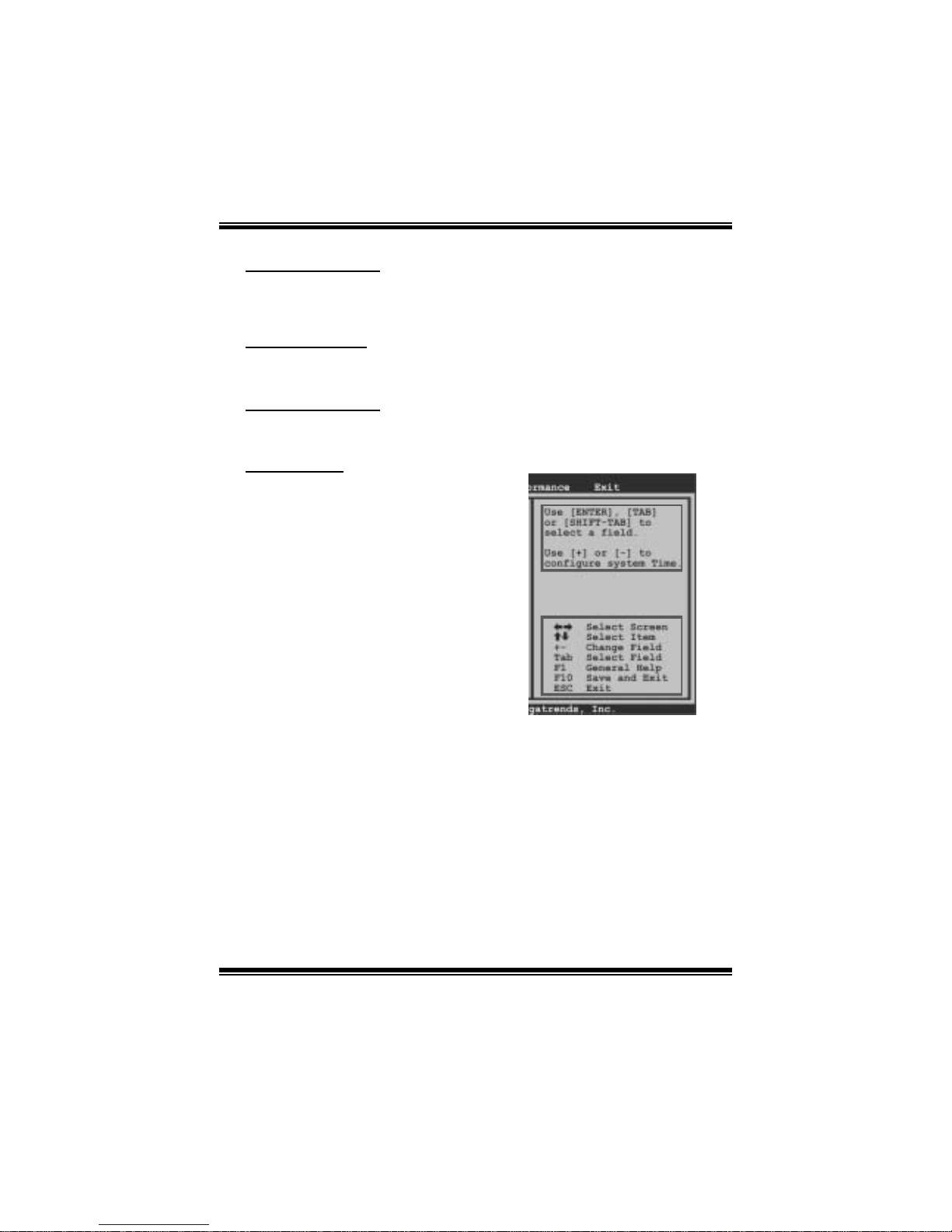
Using Setup
W hen st arting up the computer, press
<Del> during the Power-On Self-Test
(POST) to enter the BIOS setup utility.
In the BIOS setup utility, you will see
General Help description at the top right
corner, and this is providing a brief
description of the selected item.
Navigation Keys for that particular menu
are at the bottom right corner, and you can
use these k eys to sele ct item and ch ange
the settings.
Notice
z The default BIOS settings apply for most conditions to ensure optimum performance
of the motherboard. If the system becomes unstable after changing any settings,
please load the default settings to ensure system’s compatibility and stability. Use
Load Setup Default under the Exit Menu.
z For better system perform ance, the BIOS firmware is being continuously updated.
The BIOS information described in this manual is for your reference only. The actual
BIOS information and settings on board may be slightly differ ent from this manual.
z The content of this manual is subject to be changed without notice. We will not be
responsible for any mistakes found in this user’s manual and any system damage that
may be caused by wrong-settings.
General Help
Navigation Keys

TF8200 A2+ SE / T F720 A2+ / T F710 A2+
BIOS Manual
3
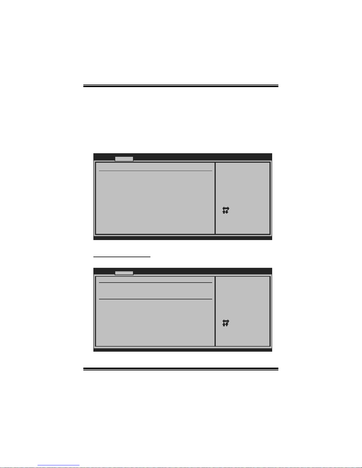
1 Main Menu
Once you enter AMI BIOS Setup Utility, the Main Menu will appear on the screen
providing an overview of the basic system inform ation.
BIOS SETU P UTILITY
Main Advan ced PCIPnP Boot Chipset T-Series
vxx .xx (C)Copyright 1985-200x, American Me gatrends, Inc.
Select Screen
Select Item
Change Field
Select Field
General Help
Save and Exit
Exit
+Tab
F1
F10
ESC
Use [ENTER], [TAB]
or [SHIFT-TAB] to
select a field.
Use [+] or [-] to
configure system Time.
System Overvie w
AMI BIOS
[ :00:00]
System Date [Tue 01/01/2008]
Floppy A
> IDE Configur ation
Version :01. 01.01
Build Date:01/ 01/08
NVMM ROM Versi on :X.XXX.XX
System Time 00
Exit
AMI BI OS
Shows system information including BIOS version, built date, etc.
System Time
Set the system internal clock.
System Date
Set the system date. Note that the ‘Day’ automatically changes when you set the
date.
Floppy A
Select the type of floppy disk drive installed in your system.
Options: 360K, 5.25 in / 1. 2M, 5.25 in / 720K, 3.5 in / 1.44M, 3.5 in /
2.88M, 3.5 in / None

TF8200 A2+ SE / T F720 A2+ / T F710 A2+
BIOS Manual
4
IDE Configuratio n
T he BIOS will automatical ly det ect the presenc e o f IDE/SAT A devices. There i s a
sub-menu for each IDE/S AT A devi ce. S elect a devi ce and press <Enter> to ent er
the sub-menu of detailed options.
BIOS SETU P UTILITY
Main
vxx .xx (C)Copyright 1985-200x, American Me gatrends, Inc.
Select Screen
Select Item
Go to Sub Screen
General Help
Save and Exit
Exit
Enter
F1
F10
ESC
DISABLED: disables the
integrated IDE
Controller.
ENABLED: enables the
integrated IDE
Controller.
IDE Confugurat ion
OnChip S-ATA C ontroller [Enab led]
SATA Mode Sele ct [SATA Mode]
> Primary IDE Master
> Primary IDE Slave
> SATA 1 Devic e
Hard Disk Writ e Protect [Disa bled]
IDE Detect Tim e Out (Sec) [35]
Change the AHC I DID for Linux[Disa bled]
> SATA 2 Devic e
> SATA 3 Devic e
> SATA 4 Devic e
OnChip P-ATA C ontroller [Enab led]
> SATA 5 Devic e
> SATA 6 Devic e
OnChip P-ATA C ontroller
This item allows you to control the onboard IDE controller.
Options: Enabled (Default) / Disabled
OnChip S-ATA C ontroller
This item allows you to control the onboard SAT A controller.
Options: Enabled (Default) / Disabled
SATA Mode Select
This item allows you to choose the SATA operation mode. To set SAT A5/SAT A6
device, please choose AHCI.
Options: SAT A Mode (Default) / RAID / AHCI / Linux AHCI
Change the AHCI DI D for Linux
This item appears only when SAT A mode is set to Linux AHCI.
Options: Disabled (Default) / Enabled

TF8200 A2+ SE / T F720 A2+ / T F710 A2+
BIOS Manual
5
Primary IDE Master/Slave ; SATA 1/2/3/4/5/6 Device
(SATA 5/6 Devi ce appears only when S ATA Mode is se t to AHCI)
BIOS SETUP UTILITY
Main
vxx.xx (C)Copyright 1985-200x, American Megatrends, Inc.
Select Screen
Select Item
Change Option
General Help
Save and Exit
Exit
+F1
F10
ESC
Select the type
of device connected
to the system.
Primary IDE Master
LBA/Large Mode [Auto]
Block (Multi-Sector Transfer)[Auto]
PIO Mode [Auto]
DMA Mode [Auto]
S.M.A.R.T [Auto]
32Bit Data Transfer [Enabled]
Device :
Type [Auto]
T he B IOS det ects t he informatio n an d values of resp ective devic es, and these
information and values are shown below to the name of the sub-menu.
Type
Select the type of the IDE/SATA drive.
Options: Auto (Default) / CDROM / ARMD / Not Installed
LBA/Large Mode
Enable or disable the LBA mode.
Options: Auto (Default) / Disabled
Block (Multi-Sector Transfer)
Enable or dis able multi-secto r trans fer.
Options: Auto (Default) / Disabled
PIO Mode
Select the PIO mode.
Options: Auto (Default) / 0 / 1 / 2 / 3 / 4
DMA Mode
Select the DMA mode.
Options: Auto (Default) / Disabled

TF8200 A2+ SE / TF720 A2+ / T F710 A2+
BIOS Manual
6
S.M.A.R.T
Set the Smart Monitoring, Analysis, and Reporting Technology.
Options: Auto (Default) / Disabled / Enabled
32Bit Data Tran sfer
Enable or disable 32-bit data transfer.
Options: Enabled (Default) / Disabled
Har d Disk Wr i te Protect
Disable or enable device write protection. This will be effective only if the device
is accessed through BIOS.
Options: Disabled (Default) / Enabled
IDE Detect Time Out (Sec)
Select the time out value for detecting IDE/SATA devices.
Options: 35 (Default) / 30 / 25 / 20 / 15 / 10 / 5 / 0
TF8200 A2+ SE / TF720 A2+ / T F710 A2+
BIOS Manual
7
2 Advanced Menu
The Advanced Menu allows you to configure the settings of CPU, Super I/O, Power
Management, and other system devices.
Notice
z Beware of that setting inappropriate values in items of this menu may cause
system to malfunction.
BIOS SETU P UTILITY
Main Advanc ed PCIPnP Boot Chipset T-Series
vxx .xx (C)Copyright 1985-200x, American M egatrends, Inc.
Select Screen
Select Item
Go to Sub Screen
General Help
Save and Exit
Exit
Enter
F1
F10
ESC
Configure CPU.Advanced Setti ngs
WARNING: Setti ng wrong values in b elow sections
may c ause system to malfu nction.
> USB Configur ation
> AUDIO Config uration
> Onboard LAN Configuration
> SuperIO Conf iguration
> Hardware Hea lth Configuration
> Smart Fan Co nfiguration
> Power Config uration
> CPU Configur ation
Exit
CPU Configurati on
This item shows the CPU information that the BIOS automatically detects.
BIOS SETU P UTILITY
Advan ced
vxx .xx (C)Copyright 1985-200x, American M egatrends, Inc.
Select Screen
Select Item
Change Option
General Help
Save and Exit
Exit
+F1
F10
ESC
Enable/Disable
Secure Virtual Machine
Mode (SVM)
CPU Configurat ion
Module Version :
AGESA Version:
Physical Count :
Logical Count:
AMD CPU
Revision:
Cache L1:
Cache L2:
Cache L3:
Speed :
Current FSB Mu ltiplier:
Maximum FSB Mu ltiplier:
Able to Change Freq :
uCode Patch Le vel :
Secure Virtual Machine Mode [Enab led]
PowerNow [Enab led]
ACPI SRAT Tabl e [Enab led]

TF8200 A2+ SE / TF720 A2+ / T F710 A2+
BIOS Manual
8
Secur e Vi r t ual Ma chine Mode
Virtualization Technology can virtually separate your system resource into several
parts, thus enhance the performance when running virtual machines or multi
interface systems.
Options: Enabled (Default) / Disabled
Powe rNow
This item allows you to enable or disable the P owerNow power saving technology.
Options: Enabled (Default) / Disabled
ACPI SRAT Tab l e
T he operati ng syst em scans t he AC P I SRAT at boot time and uses the in formation to
better allocate memory and schedule software threads for maximum perform ance.
This item controls whether the SRAT is made available to the operating system at
boot up, or not.
Options: Enabled (Default) / Disabled
S uperI O Confi gurati on
BIOS SETU P UTILITY
Advan ced
vxx .xx (C)Copyright 1985-200x, American M egatrends, Inc.
Select Screen
Select Item
Change Option
General Help
Save and Exit
Exit
+F1
F10
ESC
Allows BIOS to Enable
or Disable Floppy
Controller
Configure ITE8 718 Super IO Chipset
Onboard Floppy Controller [Enab led]
Serial Port1 A ddress [3F8/ IRQ4]
Parallel Port Address [378]
Parallel Por t Mode [Norm al]
Parallel Por t IRQ [IRQ7 ]
Keyboard Power On [Disa bled]
Mouse PowerOn [Disa bled]
Restore on AC Power Loss [Powe r Off]
Onboard Floppy Controlle r
Select enabled if your system has a floppy disk controller (FDC) installed on the
system board and you wish to use it. If you installed another F DC or the system uses
no floppy drive, select disabled in this field.
Options: Enabled (Default) / Disabled

TF8200 A2+ SE / TF720 A2+ / T F710 A2+
BIOS Manual
9
Serial Port1 Address
Select an address and corresponding interrupt fo r the first and second serial ports.
Options: 3F8/IRQ4 (Default) / 2F8/IRQ3 / 3E8/IRQ4 / 2E8/IRQ3 / Auto / Disabled
Parallel Port Address
T his i tem allows you to determine access onboard p arallel port controller with which
I/O Address.
Options: 378 (Default) / 278 / 3BC / Disabled
Parallel Port Mode
This item allows you to determine how the parallel port should function.
Options: Normal (Default) Using Parallel port as Standard Printer Port.
EPP Using Parallel Port as Enhanced Parallel Port.
ECP Using Parallel port as Extended Capabilities Port.
ECP+EPP Using Parallel port as ECP & EPP mode.
Parallel Port IRQ
This item allows you to select the IRQ for the onboard parallel port.
Options: IRQ7 (Default) / IRQ5 / Disabled
Keyboa rd PowerO n
This item allows you to control the keyboard power on function.
Options: Disabled (Default) / Enabled
Mouse PowerOn
This item allows you to control the mouse power on function.
Options: Disabled (Default) / Enabled
Res tore on AC P owe r Loss
This setting specifies how your system should behave afte r a power fail or interrupts
occurs. By choosing Dis abl ed will leave the com puter i n t he power off s tate.
Choosing Enabled will restore the system to the status before power failure or
interrupt occurs.
Options: Power Off (Default) / Power ON / Last State

TF8200 A2+ SE / TF720 A2+ / T F710 A2+
BIOS Manual
10
Hardware Health C onfiguration
This item shows the system temperature, fan speed, and voltage information.
Advan ced
Hardware Healt h Configuration
H/W Health Fun ction [Enab led]
Shutdown Tempe rature [Disa bled]
CPU Temperatur e
CPU FAN Speed
SYS FAN Speed
Chip FAN Speed
CPU Vcore
Chipset Voltag e
+3.30V
+5.00V
+12.0V
HT Voltage
Memory Voltage
5V(SB)
Voltage Batter y
BIOS SETU P UTILITY
vxx .xx (C)Copyright 1985-200x, American M egatrends, Inc.
Select Screen
Select Item
Change Option
General Help
Save and Exit
Exit
+F1
F10
ESC
Enables Hardware
Health Monitoring
Device.
H/W Health Function
If you computer contains a monitoring system, it will show PC health status during
POST stage.
Options: Enabled (Default) / Disabled
Shutdow n Tempe r ature
This item allows you to set up the CPU shutdown Temperature. This item is only
effective under Windows 98 ACPI mode.
Options: Disabled (Default) / 60℃/140℉ / 65℃/149℉ / 70℃/158℉ / 7 5 ℃/167℉
/ 80℃/176℉ / 85℃/185℉ / 90℃/194℉

TF8200 A2+ SE / TF720 A2+ / T F710 A2+
BIOS Manual
11
Smart Fan Configuration
BIOS SETU P UTILITY
Advan ced
vxx .xx (C)Copyright 1985-200x, American M egatrends, Inc.
Select Screen
Select Item
Change Option
General Help
Save and Exit
Exit
+F1
F10
ESC
When you choice [Auto]
,[3Pin] or [4Pin],
please run the
calibration to define
the Fan parameters for
Smart Fan control
Smart Fan Conf iguration
CPU Smart Fan [Disa bled]
Smart Fan Cali bration
Control Mode
Fan Ctrl OFF( C )
o
Fan Ctrl On(C)
Fan Ctrl Start value
Fan Ctrl Sensi tive
o
CPU Sm art Fa n
This item allows you to control the CPU Smart Fan function.
Options: Disabled (default) / Auto / 4-pin / 3-pin
Sm art Fan Calibr a tion
Choose this item and then the BIOS will auto test and detect the CPU/System fan
fun ctions and show CPU/System fan speed.
Control Mode
This item provides several operation modes of the fan.
Options: Quiet / Performan ce / Manual
Fan Ctrl OF F(℃)
If the CPU/System T emperature is lower than the set value, FAN will turn off.
Options: 0~127 (℃)
Fan Ctrl On(℃ )
CPU/System fan starts to work under smart fan function when arrive this set value.
Options: 0~127 (℃)
 Loading...