

Page 1

T5 XE/T5XE CFX-SLI Setup Manual
FCC Information and Copyright
This equipment has been tested and found to comply with the limits of a Class
B digital device, pursuant to Part 15 of the FCC Rules. These limits are designed
to provide reasonable protection against harmful interference in a residential
installation. This equipment generates, uses, and can radiate radio frequency
energy and, if not installed and used in accordance with the instructions, may
cause harmful interference to radio communications. There is no guarantee
that interference will not occur in a particular installation.
The vendor makes no representations or warranties with respect to the
contents here and specially disclaims any implied warranties of merchantability
or fitness for any purpose. Further the vendor reserves the right to revise this
publication and to make changes to the contents here without obligation to
notify any party beforehand.
Duplication of this publication, in part or in whole, is not allowed without first
obtaining the vendor’s approval in writing.
The content of this user’s manual is subject to be changed without notice and
we will not be responsible for any mistakes found in this user’s manual. All the
brand and product names are trademarks of their respective companies.
Page 2

Table of Contents
Chapter 1: Introduction ........................................ 1
1.1 Before You Start......................................................................................... 1
1.2 Package Checklist..................................................................................... 1
1.3 Motherboard Features.............................................................................. 2
1.4 Rear Panel Connectors.............................................................................. 2
1.5 Motherboard Layout................................................................................. 4
Chapter 2: Hardware Installation .......................... 5
2.1 Installing Central Processing Unit (CPU) ............................................... 5
2.2 FAN Headers.............................................................................................. 7
2.3 Installing System Memory ........................................................................ 8
2.4 Connectors and Slots................................................................................ 10
Chapter 3: Headers & Jumpers Setup .................. 14
3.1 How to Setup Jumpers............................................................................. 14
3.2 Detail Settings .......................................................................................... 14
Chapter 4: T-Series BIOS & Software................... 19
4.1 T-Series BIOS............................................................................................. 19
4.2 T-Series Software...................................................................................... 27
Chapter 5: Useful Help ........................................ 27
5.1 Driver Installation Note.......................................................................... 37
5.2 Extra Information.................................................................................... 38
5.3 AMI BIOS Beep Code............................................................................... 39
5.4 Troubleshooting....................................................................................... 40
Appendix: SPEC In Other Languages ................... 41
German.................................................................................................................. 42
French .................................................................................................................... 44
Italian..................................................................................................................... 46
Spanish ................................................................................................................... 48
Portugue se ............................................................................................................ 50
Polish...................................................................................................................... 52
Russian ................................................................................................................... 54
Arabic..................................................................................................................... 56
Japanese ................................................................................................................ 58
Page 3

CHAPTER 1: INTRODUCTION
T5 XE/T5XE CFX-SLI
1.1 B
EFORE YOU START
Thank you for choosing our product. Before you start installing the
motherboard, please make sure you follow the instructions below:
Prepare a dry and stable working environment with
sufficient lighting.
Always disconnect the computer from power outlet
before operation.
Before you take the motherboard out from anti-static
bag, ground yourself properly by touching any safely
grounded appliance, or use grounded wrist strap to
remove the static charge.
Avoid touching the components on motherboard or the
rear side of the board unless necessary. Hold the board
on the edge, do not try to bend or flex the board.
Do not leave any unfastened small parts inside the
case after installation. Loose parts will cause short
circuits which may damage the equipment.
Keep the computer from dangerous area, such as heat
source, humid air and water.
The operating temperatures of the computer should be
0 to 45 degrees Celsius.
1.2 PACKAGE CHECKLIST
HDD Cable X 1 (optional)
Serial ATA Cable X 3
Rear I/O Panel for ATX Case X 1
User’s Manual X 1
Fully Setup Driver CD X 1
FDD Cable X 1 (optional)
USB 2.0 Cable X1 (optional)
Serial ATA Power Cable X 1 (optional)
SLI / CrossfireX bridge (T5XE CFX-SLI only)
Note: The package contents may be different due to area or your motherboard version.
1
Page 4
Motherboard Manual
1.3 MOTHERBOARD FEATURES
CPU
Chipset
Socket 1156
Int e l Co re i7 / i5 pro cessor
Intel P55
SPEC
Supports Execute Disab le B it / Enhanced Intel
SpeedSt ep® / Intel Ar ch itecture- 64 / Ext ended
Memory 64 Technology / Virtualization
Technology
Super I/O
Main
Memory
IDE
SATA 2
LAN
Sound
Codec
IT8720
Prov ides the most common ly used leg acy Super
I/O functionality.
Low Pin Count Interface
DDR3 DIMM Slots x 4
Max Memory Capacity 16GB
Each DIMM supports 512MB/ 1GB/2GB/4GB
DDR3
JMB368
Integrated Serial ATA Controller
Realtek RTL 8111DL
ALC888
En v ironm en t Cont rol in itiatives ,
Hardware Monitor Controller
Fan Sp eed Controller
ITE's "S mart Guard ian" function
Dual Ch annel Mode DDR3 me mory mod u le
Supports DDR3 800 / 1066 / 1333
Supports DDR3 1600 (OC) / 1866 (OC)
Register ed D IMM and ECC D IMM is not
supported
Ultra DMA 33 / 66 / 100 / 133 Bus Master Mode
supports PIO Mode 0~4
Data transfer rates up to 3.0 Gb/s.
SATA Version 2 .0 s p e c if icat ion co mpl ian t
10 / 100 Mb/s / 1Gb/s auto negot iation
Half / Full duplex capability
7.1 channels audio out
High Definition Audio
PCI slot x2 Supports PCI expansion cards
Slots
On Board
Connectors
PCI Express Gen2 x 16 slot x2 Supports PCI-E Gen2 x16 expansion cards
PCI Express Gen2 x 1 slot x2 Supports PCI-E Gen2 x1 expansion cards
Floppy Connector x1 Each connector supports 2 Floppy drives
IDE Conn ector x1 Each conne ctor s upports 2 IDE device
SATA Connector x6 Each conne cto r s upports 1 SATA devices
2
Page 5
T5 XE/T5XE CFX-SLI
SPEC
Front Panel Connector x1 Supports front panel facilit ies
Front Audio Connector x1 Supports front panel audio function
CD-in Connector x1 Supports CD audio-in function
S/PDIF out Connector x1 Supports digital audio out function
CPU Fan Header x1 CPU Fan power supply (with Smart Fan function)
System Fan Header x2 System Fan Power supply
Clear CMOS Head er x1 Restore CMOS dat a to facto ry default
USB Connecto r x2 Each connector s upports 2 front panel USB port s
Serial Port Connector x1 Connects to RS-232 Port
Power Connector (24pin) x1 Connects to Power supply
Power Connector (4pin) x1 Connects to Power supply
PS/2 Keybo ard x1
Back Panel
I/O
Board Size
OS Support
PS/2 Mous e x1
LAN port x1
USB Port x6
Audio Jack x6
220 (W) x 305 (L) mm
Windows XP / Vista 32 / Vista 64 / 7
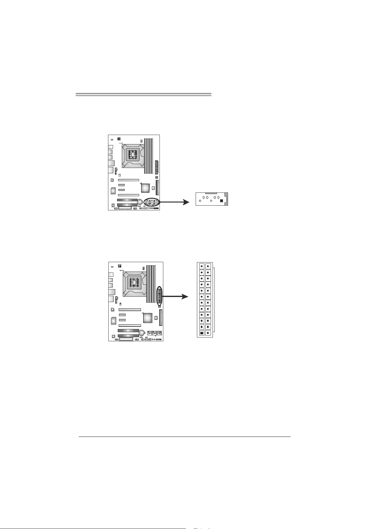
1.4 REAR PANEL CONNECTORS
PS/2
Mouse
PS/2
Keyboar d
USBX2
Cent er
Surround
USBX2 U SBX2
Connects to PS/2 Keyboard
Connects to PS/2 Mouse
Connect to RJ- 45 ethe rnet cab le
Connect to USB devices
Provide Audio-In/Out and Mic. connection
Biostar reserves the right to add or remove
support for any OS with or without notice
LAN
Line I n
Line Out
Si desur round
Mic In
3
Page 6

Motherboard Manual
1.5 MOTHERBOARD LAYOUT
AT XPW R2
JUSBV1
VTT_D1
VTT_D2
PH4 _D4
PH4 _D3
PH4 _D2
KBMS1
PH4 _D1
Socket 1156
USB2
CPU_ FAN1
CPU1
USB1
RJ45USB1
AUDIO2
LAN
Super
I/O
CD_ IN1
SPDIF1
SYS_FAN2
PEX1_1
PEX1_2
PEX16_1
PEX16_2
PCI1
BAT1
DDR3_A2
P55
SATA6
SATA5
DDR3_B2
DDR3_B1
DDR3_A1
AT XPW R1
BIOS
SATA2
SATA1
IDE 1
SATA4
SATA3
IDE
4
CODEC
F_AUD IO1
Note: represents the 1■
FDD1
PCI2
st
pin.
JUSBV2
SW _ P WR
SW_ RST
LE D 1LED2
PA N E L 1
JCMOS1
SYS_FAN1
F_USB2 F_USB1F_COM1
Page 7
T5 XE/T5XE CFX-SLI
CHAPTER 2: HARDWARE INSTALLATION
2.1 I
NSTALLING CENTRAL PROCESSING UNIT (CPU)
Special Notice:
Remove Pin Cap before installation, and make good preservation
for future use. When the CPU is removed, cover the Pin Cap on the
empty socket to ensure pin legs won’t be damaged.
Step 1: Pull the socket locking lever out from the socket and then raise
the lever up.
Step 2: Remove the Pin Cap.
5
Page 8
Motherboard Manual
Step 3: Look for the triangular cut edge on socket, and the golden dot on
CPU should point forwards this triangular cut edge. The CPU will
fit only in the correct orientation.
Step 4: Hold the CPU down firmly, and then lower the lever to locked
position to complete the installation.
Step 5: Put the CPU Fan and heatsink assembly on the CPU and buckle it
on the retention frame. Connect the CPU FAN power cable into
the CPU_FAN1 to complete the installation.
6
Page 9
T5 XE/T5XE CFX-SLI
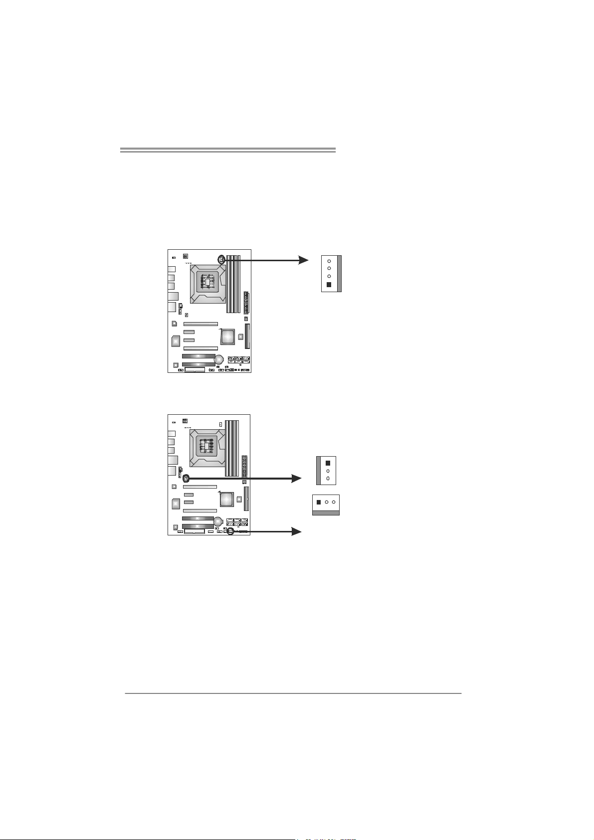
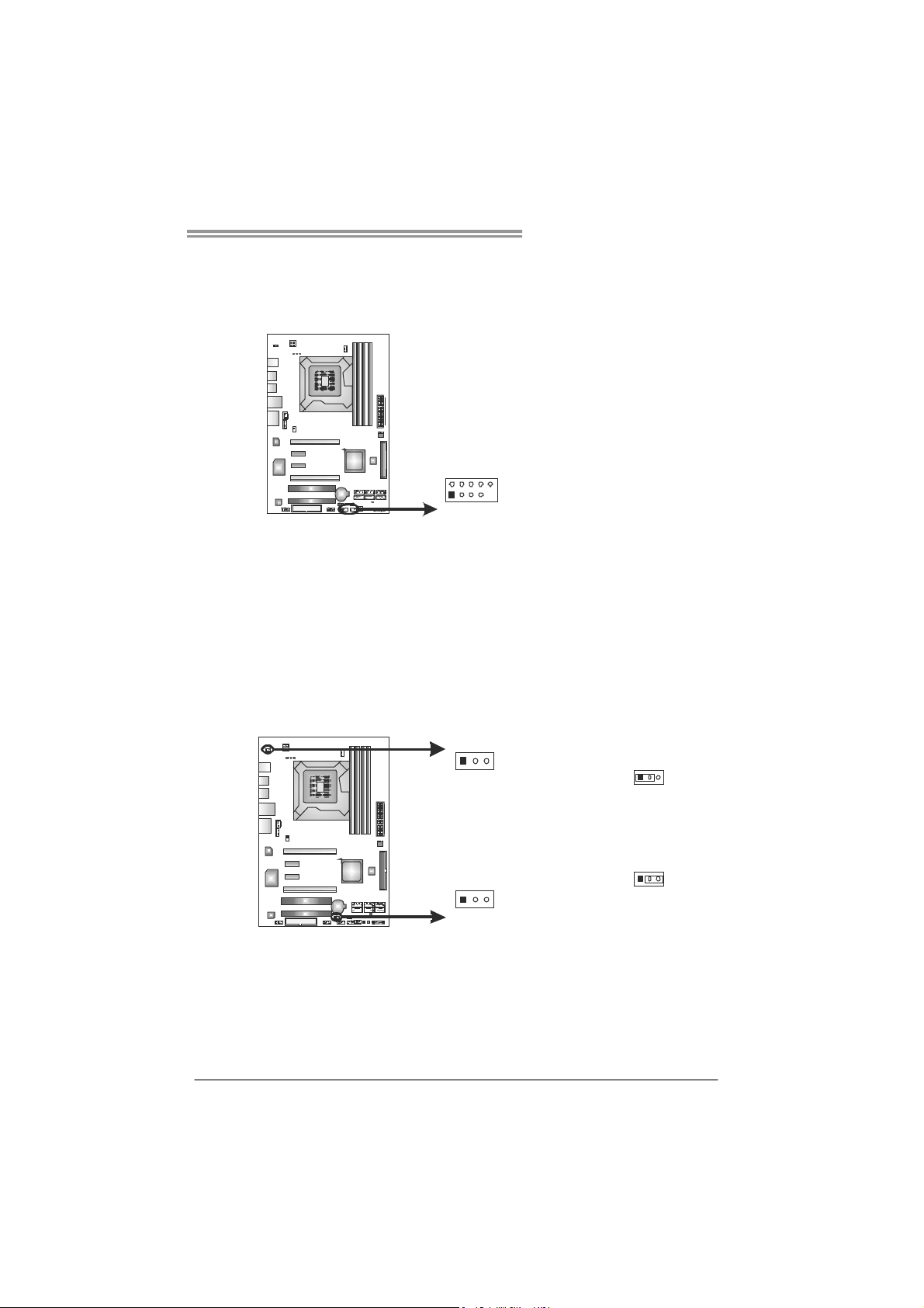
2.2 FAN HEADERS
These fan headers support cooling-fans built in the computer. The fan
cable and connector may be different according to the fan manufacturer.
Connect the fan cable to the connector while matching the black wire to
pin#1.
CPU_FAN1: CPU Fan Header
4
1
SYS_FAN1/SYS_FAN2: System Fan Headers
SYS_FAN2
1
3
Pin
Assignment
1 Ground
2 +12V
3
FAN RPM r ate
sense
4 Smart Fan
Control
Pin
Assignment
1 Ground
2 +12V
3 FAN RPM rate
sense
13
SYS_FAN1
Note:
The SYS_FAN1/SYS_FAN2 support 3-pin head connectors; the CPU_FAN1 supports
4-pin head connector. When connecting with wires onto connectors, please note that the
red wire is the positive a nd should be connected to pin#2, and the black wire is Ground
and should be co nnected to GND.
7
Page 10
Motherboard Manual
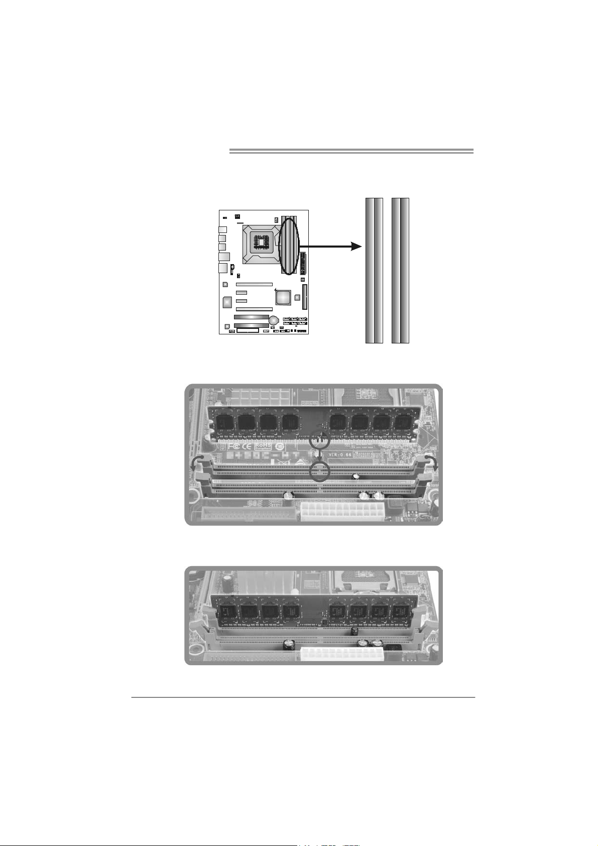
2.3 INSTALLING SYSTEM MEMORY
A. Memory Modules
DDR3 _A2
DDR3 _B2
DDR3 _A1
DDR3 _B1
1. Unlock a DIMM slot by pressing the retaining clips outward. Align a
DIMM on the slot such that the notch on the DIMM matches the
break on the Slot.
2. Insert the DIMM vertically and firmly into the slot until the retaining
chip snap back in place and the DIMM is properly seated.
8
Page 11
T5 XE/T5XE CFX-SLI
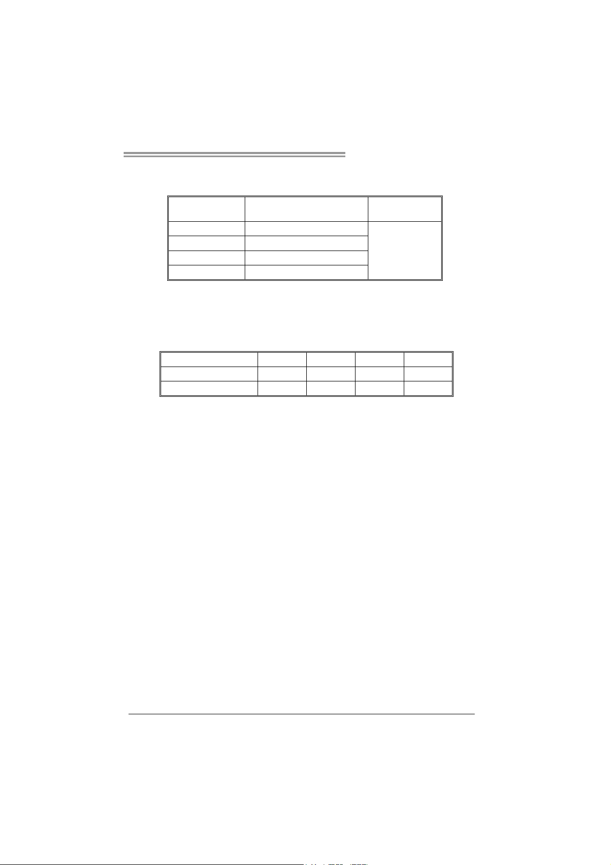
B. Memory Capacity
DIMM Socket
Location
DDR3_A1 512MB/1GB/2GB/4GB
DDR3_A2 512MB/1GB/2GB/4GB
DDR3_B1 512MB/1GB/2GB/4GB
DDR3_B2 512MB/1GB/2GB/4GB
DDR3 Module
Total Mem o ry
Size
Max is 16GB.
C. Dual Channel Memory Installation
Please refer to the following requirements to activate Dual Channel function:
Install memory module of the same density in pairs, shown in the table.
Dual Channel Status
Enabled O X O X
Enabled O O O O
(O means memory installed, X means memory not installed.)
The DRAM bus width of the memory module must be the same (x8 or
x16)
Note:
Memory mod ule must be installed in DDR3-A1 or DDR3-B1 to boot the
system.
DDR3_A1
DDR3_A2 DDR3_B1 DDR3_B2
9
Page 12
Motherboard Manual
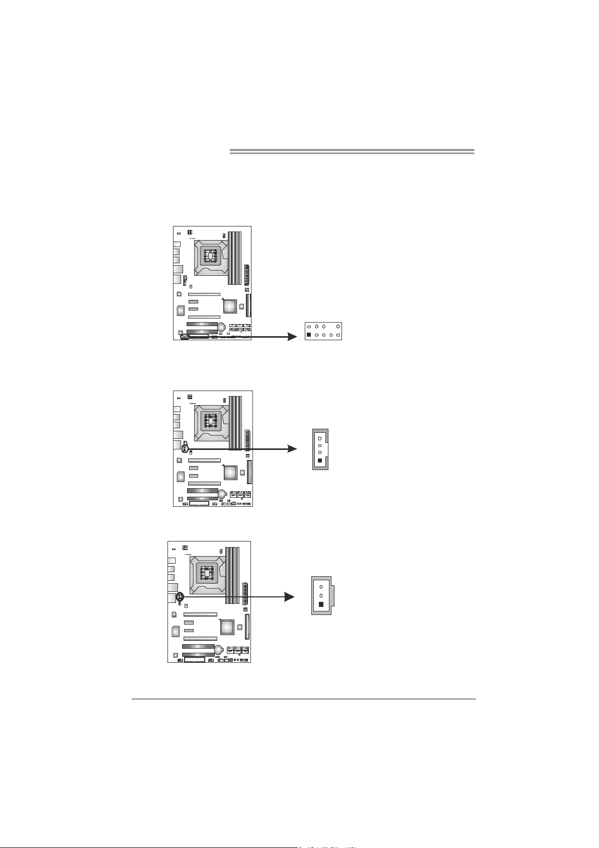
2.4 CONNECTORS AND SLOTS
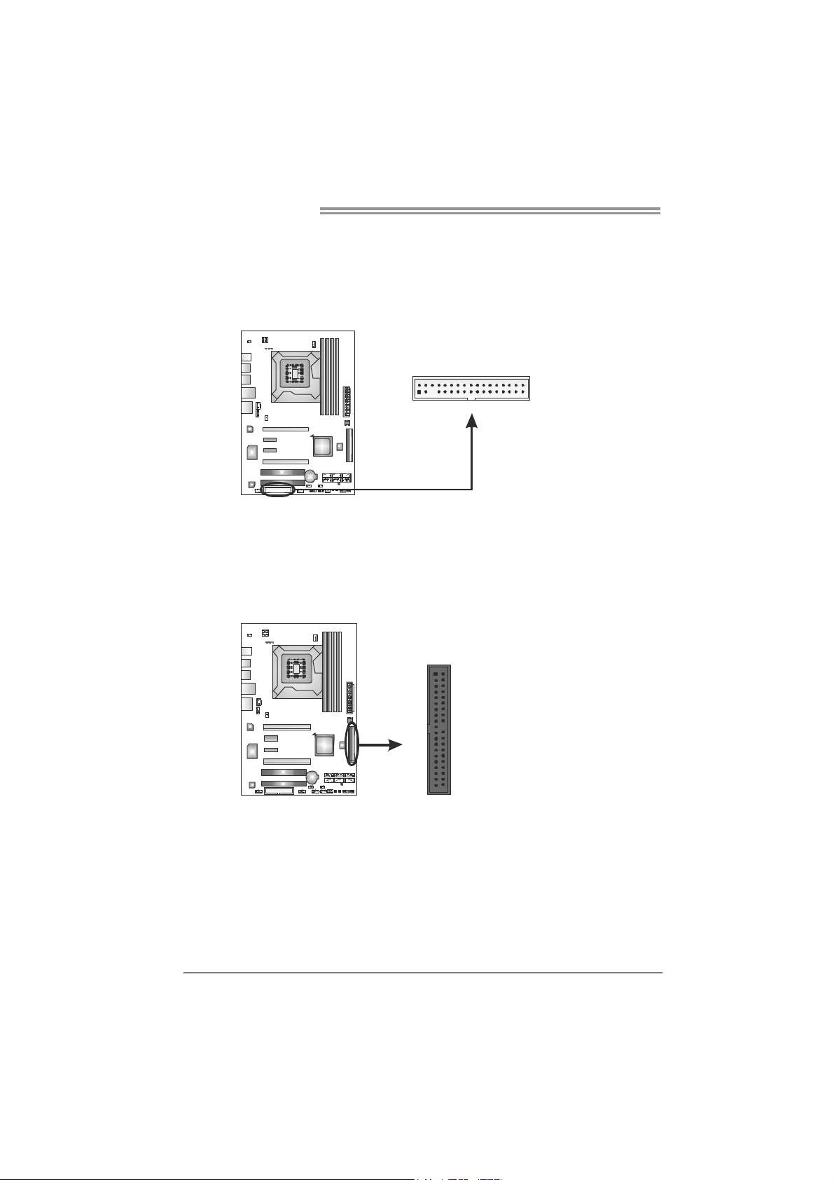
FDD1: Floppy Disk Connector
The motherboard provides a standard floppy disk connector that supports 360K,
720K, 1.2M, 1.44M and 2.88M floppy disk types. This connector supports the
provided floppy drive ribbon cables.
234
IDE1: Hard Disk Connector
The motherboard has a 32-bit Enhanced PCI IDE Controller that provides PIO
Mode 0~4, Bus Master, and Ultra DMA 33/66/100/133 functionality.
The IDE connector can connect a master and a slave drive, so you can connect
up to two hard disk drives.
1
12
4039
33
10
Page 13
T5 XE/T5XE CFX-SLI
SATA1~SATA6: Serial ATA Connectors
The motherboard has a PCI to SATA Controller with 6 channels SATA interface,
it satisfies the SATA 2.0 spec and with transfer rate of 3.0Gb/s.
Pin
Assignment
1 Ground
2 TX+
3 TX-
SATA6
SATA5
SATA4
SATA3
SATA2
SATA1
4 Ground
5 RX6 RX+
7 Ground
147
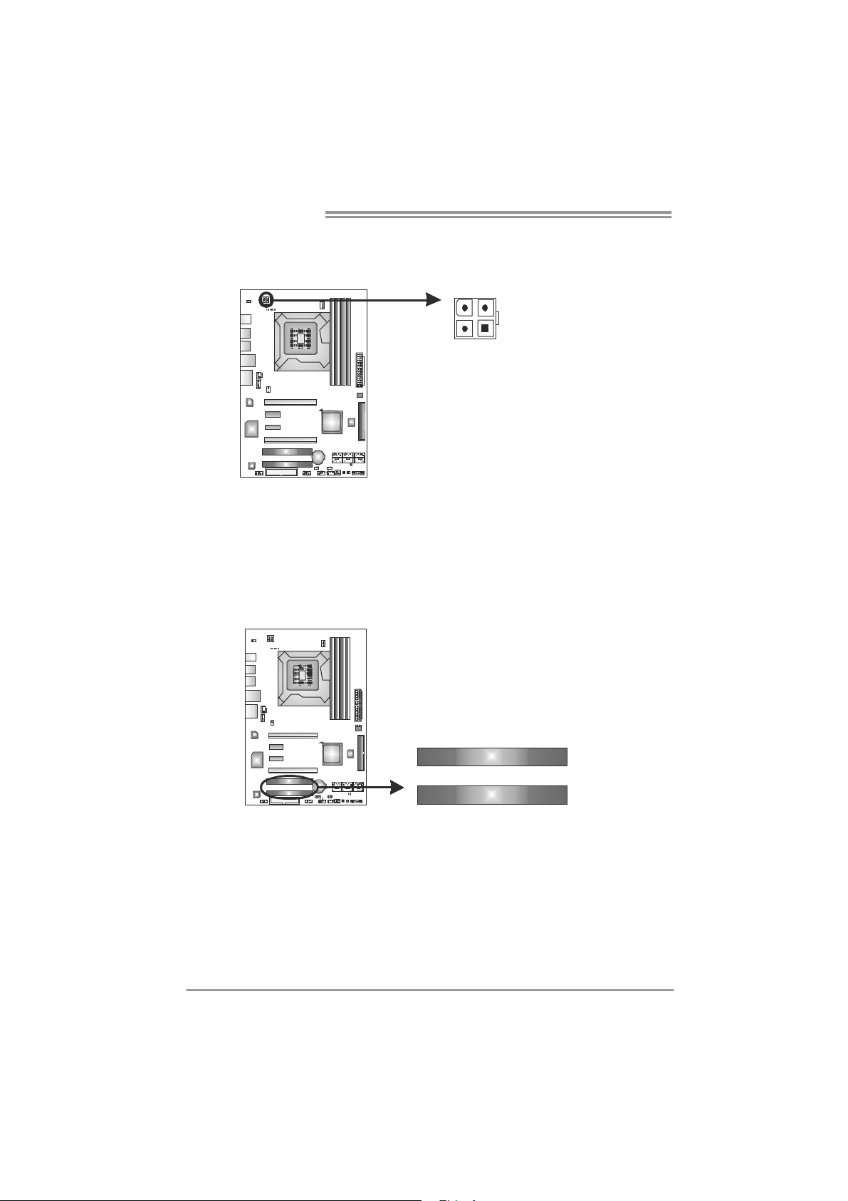
ATXP W R1: ATX Power Source Connector
This connector allows user to connect 24-pin power connector on the ATX
power supply.
12
1
Pin Assignment Pin Assignment
13 +3.3V 1 +3.3V
14 -12V 2 +3.3V
15 Ground 3 Ground
16 PS_ON 4 +5V
17 Ground 5 Ground
18 Ground 6 +5V
19 Ground 7 Ground
20 NC 8 PW_OK
21 +5V 9 Standby Voltage+5V
22 +5V 10 +12V
23 +5V 11 +12V
24 Ground 12 +3.3V
24
13
11
Page 14
Motherboard Manual
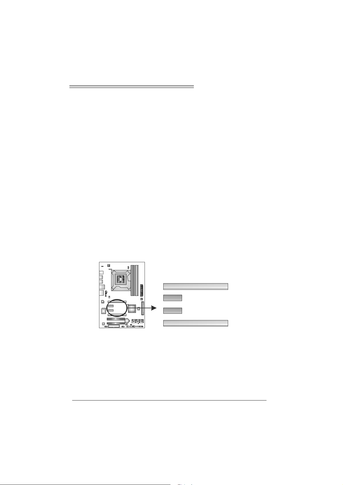
ATXP W R2: ATX Power Source Connector
This connector provides +12V to CPU power circuit.
1234
Note:
Before you power on the system, please make sure that both ATXPWR1 and ATXPWR2
connectors have been well plugged-in.
PCI1/PCI2: Peripheral Component Interconnect Slots
This motherboard is equipped with 2 standard PCI slots. PCI stands for
Peripheral Component Interconnect, and it is a bus standard for expansion
cards. This PCI slot is designated as 32 bits.
Pin
Assignment
1 +12V
2 +12V
3 Ground
4 Ground
12
PC I1
PCI2
Page 15
T5 XE/T5XE CFX-SLI
PEX16_1: PCI-Express Gen2 x16 (x16/CrossFireX x8, SLI x8 Speed) Slot
- PCI-Express 2.0 compliant.
- Maximum theoretical realized bandwidth of 8GB/s (4GB/s CrossFireX/SLI)
simultaneously per direction, for an aggregate of 16GB/s(8GB/s
CrossFireX/SLI) totally.
- PEX16_1 & PEX16_2 slots are reserved for graphic or video cards. The
design of this motherboard supports dual PCI-Express graphics cards using
CrossFireX/SLI technology with multiple displays. When CrossFireX/SLI is
activated, these slots run with x8 speed.
PEX16_2: PCI-Express Gen2 x8 (x8/CrossFireX x8, SLI x8 Speed) Slot
- PCI-Express 2.0 compliant.
- Maximum theoretical realized bandwidth of 4GB/s (4GB/s CrossFireX/SLI)
simultaneously per direction, for an aggregate of 8GB/s(8GB/s
CrossFireX/SLI) totally.
Note:
SLI function is for T5XE CFX-SLI o nly
PEX1_1/PEX1_2: PCI-Express Gen 2x1 Slots
- PCI-Express 2.0 compliant.
- Data transfer bandwidth up to 500MB/s per direction; 1GB/s in total.
- PCI-Express supports a raw bit-rate of 2.5Gb/s on the data pins.
- 2X bandwidth over the PCI architecture.
PEX16_1
PEX1_1
PEX1_2
PEX16_2
13
Page 16
Motherboard Manual
CHAPTER 3: HEADERS & JUMPERS SETUP
3.1 H
OW TO SETUP JUMPERS
The illustration shows how to set up jumpers. When the jumper cap is
placed on pins, the jumper is “close”, if not, that means the jumper is
“open”.
Pin opened Pin closed Pin1-2 closed
3.2 D
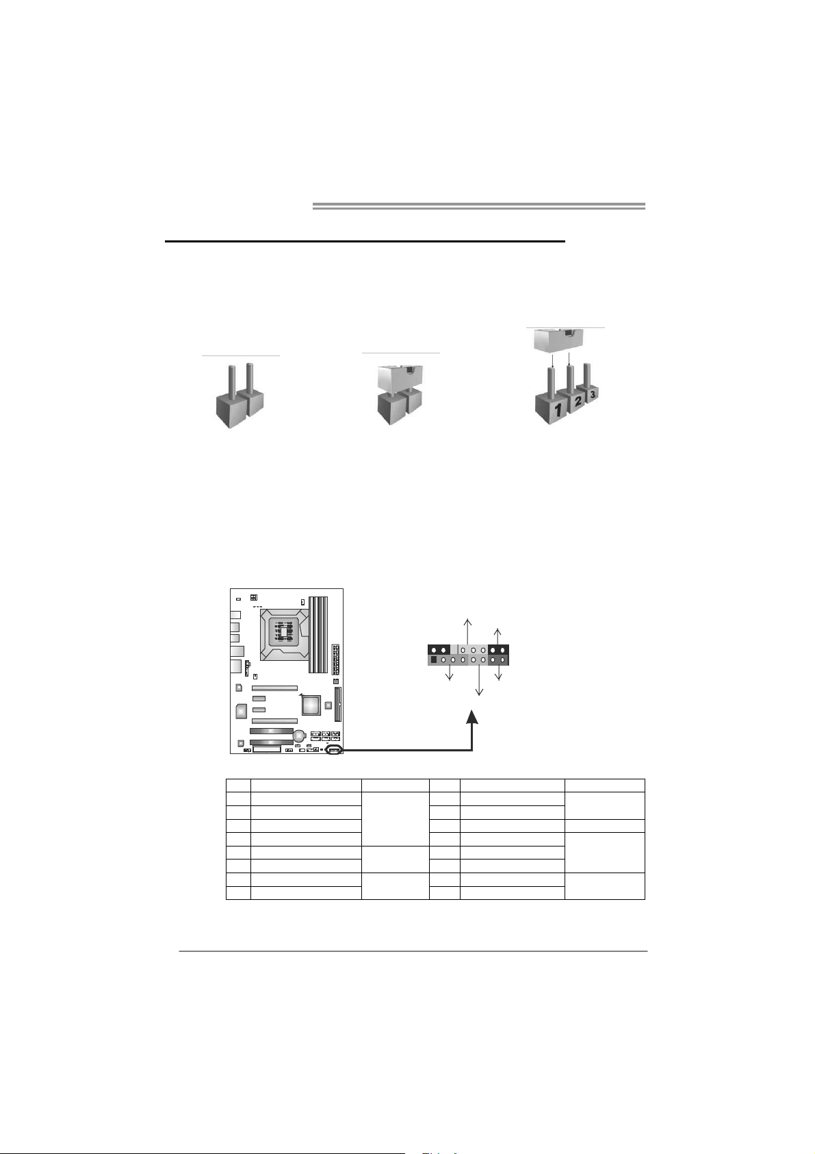
PANEL1: Front Panel Header
ETAIL SETTINGS
This 16-pin connector includes Power-on, Reset, HDD LED, Power LED, and
speaker connection. It allows user to connect the PC case’s front panel switch
functions.
POW_LE D
On/Off
-
++
9
1
SPK
+
HL ED
-
16
8
RST
14
Pin Assignment Function Pin Assignment Function
1 +5V 9 N/A
2 N/A 10 N/A
3 N/ A 1 1 N/ A N/A
4 Speaker
5 HDD LED (+) 13 Power LED (+)
6 HDD LED (-)
7 Ground 15 Power button
8 Reset control
Speaker
Connector
Hard drive
LED
Reset button
12 Power LED (+)
14 Power LED (-)
16 Ground
N/A
Power LED
Power-on button
Page 17
T5 XE/T5XE CFX-SLI
3
3
F_USB1/F_USB2: Headers for USB 2.0 Ports at Front Panel
These headers allow user to connect additional USB cable on the PC front panel,
and also can be connected with internal USB devices, like USB card reader.
F_ USB1USB2 F_
2910
1
JUSBV1/JUSBV2: Power Source Headers for USB Ports
Pin 1-2 Close:
JUSBV1: +5V for USB ports at USB1/USB2/RJ45USB1.
JUSBV2: +5V for USB ports at F_USB1/F_USB2.
Pin 2-3 Close:
JUSBV1: +5V STB for USB ports at USB1/USB2/RJ45USB1.
JUSBV2: +5V STB for USB ports at F_USB1/F_USB2.
13
JUSBV1
Assignment
Pin
1 +5V (fused)
2 +5V (fused)
3 USB4 USB5 USB+
6 USB+
7 Ground
8 Ground
9 Key
10 NC
1
Pin 1-2 close
1
13
JUSBV2
Pin 2-3 close
15
Page 18
Motherboard Manual
F_AUDIO1: Front Panel Audio Header
This header allows user to connect the front audio output cable with the PC front
panel. This header allows only HD audio front panel connector; AC’97 connector
is not acceptable.
CD_IN1: CD-ROM Audio-in Connector
This connector allows user to connect the audio source from the variaty devices,
like CD-ROM, DVD-ROM, PCI sound card, PCI TV turner card etc..
Pin Assignment
1 Mic Left in
2 Ground
3 Mic Right in
4 GPIO
5 Right line in
6 Jack Sense
7 Front Sense
2
10
1
9
4
1
8 Key
9 Left line in
10 Jack Sense
Assignment
Pin
1 Left Channel Input
2 Ground
3 Ground
4 Right Channel Input
SPDIF1: Digital Audio-out Connector
This connector allows user to connect the PCI bracket SPDIF output header.
16
Pin
3
1
Assignment
1 +5V
2 SPDIF_OUT
3 Ground
Page 19
T5 XE/T5XE CFX-SLI
3
3
JCMOS1: Clear CMOS Header
Placing the jumper on pin2-3 allows user to restore the BIOS safe setting and
the CMOS data. Please carefully follow the procedures to avoid damaging the
motherboard.
1
1
13
Pin 1-2 Close:
Normal Operation (default).
Pin 2-3 Close:
Clear CMOS data.
※ Clear CMOS Procedures:
1. Remove AC power line.
2. Set the jumper to “Pin 2-3 close” .
3. Wait for five seconds.
4. Set the jumper to “Pin 1-2 close” .
5. Power on the AC.
6. Reset your desired password or clear the CMOS data.
F_COM1: Serial port Connector
The motherboard has a Serial Port Connector for connecting RS-232 Port.
Pin
Assignment
1 Carrier detect
2 Received data
3 Transmitted data
4 Data terminal ready
5 Signal ground
6 Data set ready
210
19
7 Request to send
8 Clear to send
9 Ring indicator
10 NC
17
Page 20

Motherboard Manual
On-Board LED Indicators
There are 8 LED indicators on the motherboard showing system status.
LED1 & LED2: Debug Indicators
PH1_D1 ~ PH4_D4/VTT_D1 ~ VTT_D2: Power Status Indicators
Please refer to the tables below for specific messages:
LED1 LED2 Message
ON ON Norma l
ON OFF Memory Error
OFF ON VGA Error
OFF OFF Abnormal: CPU / Chipset error.
PH1_D1 ~ PH4_D4
VTT_D1 ~ VTT_D2
ON Phase Active
OFF Phase Inactive
On-Board Buttons
There are 2 on-board buttons.
Phase Indicator
PH3_D3
PH4_D4
PH1_D1
PH2_D2
VTT_D 2
VTT_D 1
LED_D1
LED_D2
18
SW_RST1: Reset button.
SW_PWR1: Power Switch button.
SW_RST
SW_PWR
Page 21

T5 XE/T5XE CFX-SLI
CHAPTER 4: T-SERIES BIOS & SOFTWARE
4.1 T-S
ERIES BIOS
T-Series BIOS Features
Overclocking Navigator Engine (O.N.E.)
Memory Integration Test (M.I.T., under Overclock Navigator Engine)
BIO-Flasher: Update BIOS file from USB Flash Drive or FDD
Self Recovery System (S.R.S)
Smart Fan Function
CMOS Reloading Program
!! WARNING !!
For better system performance, the BIOS firmware is being
continuously updated. The BIOS information described below in
this manual is for your reference only and the actual BIOS
information and settings on board may be different from this
manual. For further information of setting up the BIOS, please
refer to the BIOS Manual in the Setup CD.
A. Overclocking Navigator Engine (O.N.E.)
ONE provides two powerful overclocking engines: MOS and AOS for both
Elite and Casual overclockers.
Main Advanced
Over-Clocking Navigator Setting
WARNING:Please Clear CMOS if system no display
after overclocking
Over-Clocking Navigator [Normal]
=========== Automate OverClock System ===========
Auto OverClock System [V6-Tech Engine]
============ Manual OverClock System ============
Current CPU Frequency :
Current Memory Frequency :
Over Clock Retry Count [1]
Intel(R) SpeedStep(tm) tech [Enabled]
CPU Ratio Setting [ x21.0]
CPU Frequency Setting [133]
DRAM Frequency [Auto]
> DRAM Timing Configuration
> Clock Gen Configuration
> Voltage Control
> Intel PPM Configuration
vxx.xx (C)Copyright 1985-200x, American Megatrends, Inc.
PCIPnP Boot
BIOS SETUP UTILITY
Chipset O.N.E
Exit
Options
Normal
Automate OverClock
Manual OverClock
Select Screen
Select Item
Go to Sub Screen
Enter
General Help
F1
Save and Exit
F10
Exit
ESC
19
Page 22

Motherboard Manual
Manual Overclock System (M.O.S.)
MOS is designed for experienced overclock users.
It allows users to customize personal overclock settings.
Main Advanced PCIPnP Boot Chipset O.N. E
Over-Clocking Navigator Setting
WARNING:Please Clear CMOS if system no display
after ov er clo ckin g
Over-Clocking Navigator [Normal]
=========== Automate OverClock System ===========
Aut o Ov erCloc k Sy stem [ V6 -Tech En gi ne]
============ Manual OverClock System ============
Current CPU Frequency :
Current Memory Frequency :
Ove r Cl ock Retr y Co unt [ 1]
Intel(R) SpeedStep(tm) tech [Enabled]
CPU Ratio Setting [ x21.0]
CPU Frequency Setting [133]
DRA M Fr equenc y [ Au to ]
> D RA M Timi ng Con fi gur atio n
> Clock Gen Configuration
> Voltage Control
> Intel PPM Configuration
Main Advanced PCIPnP Boot Chipset O.N. E
Over-Clocking Navigator Setting
WARNING:Please Clear CMOS if system no display
after ov er clo ckin g
Over-Clocking Navigator [Manual OverClock]
=========== Automate OverClock System ===========
Aut o Ov erCloc k Sy stem [ V6 -Tech En gi ne]
============ Manual OverClock System ============
Current CPU Frequency :
Current Memory Frequency :
Ove r Cl ock Retr y Co unt [ 1]
Intel(R) SpeedStep(tm) tech [Enabled]
CPU Ratio Setting [ x21.0]
CPU Frequency Setting [133]
DRA M Fr equenc y [ Au to ]
> D RA M Timi ng Con fi gur atio n
> Clock Gen Configuration
> Voltage Control
> Intel PPM Configuration
Over Clock Re try Count
This item allows you to set the overclock fail retry times.
Intel(R) SpeedStep(tm) Tech
This item allows you to enable SpeedStep technology for better power
saving. SpeedStep is a technology built into some Intel processors that
allows the clock speed of the processor to be dynamically changed by
software.
CPU Ratio Setting
This item allows you to set the CPU ratio frequency. This item is adjustable
only when SpeedStep Tech is set to Disabled
CPU Fre q ue ncy Se tting
This item allows you to select the CPU Frequency.
BIOS SETUP UTILITY
Options
Norm al
Auto ma te Ove rC lock
Manual OverClock
vxx. xx (C)Copyr ig ht 198 5- 20 0x, Am er ican Mega tr ends , In c.
Exit
Opti on s
Normal
Automate OverClock
Man ua l OverCl oc k
Select Screen
Select Item
Go to Sub Screen
Ente r
General Help
F1
Sav e an d Exit
F10
Exit
ESC
↓
BIOS SETUP UTILITY
vxx. xx (C)Copyr ig ht 198 5- 20 0x, Am er ican Mega tr ends , In c.
Exit
Opti on s
Normal
Automate OverClock
Man ua l OverCl oc k
Select Screen
Select Item
Go to Sub Screen
Ente r
General Help
F1
Sav e an d Exit
F10
Exit
ESC
20
Page 23

T5 XE/T5XE CFX-SLI
DRAM Fre que nc y
To get better system performance, sometimes downgrading the memory
frequency is necessary when CPU frequency is adjusted over the upper
limit.
DRAM Timing Config uration
Enter this item for more advanced DRAM timing settings.
Clo ck Ge n Co nf ig urat io n
Enter this item for more advanced Clock Gen settings.
Voltage Control
Enter this item for more advanced voltage settings.
Inte l PPM Configuration
Enter this item for more advanced Intel PPM settings.
BIOSTAR Me mory Insig ht
Enter this item for more advanced memory SPD information.
G.P.U Phase Control
Enter this function for more power saving settings.
NOTE
Overclock is an optional process, but not a “must-do” process; it is not
recommended for inexperienced users. Therefore, we will not be responsible
for any hardware damage which may be caused by overclocking. We also
woul d no t guarantee any overclocking performance.
Automatic Overclock System (A.O.S.)
For beginners i n overc lock field, BET had develope d an easy, fa st, an d
powerful feature to increase the system performance, named A.O.S.
Based on many tests and experiments, A.O.S. provides 3 ideal overclock
configurations that are able to raise the system performance in a single step.
Main Advanced PCIPnP Boot Chipset O.N. E
Over-Clocking Navigator Setting
WARNING:Please Clear CMOS if system no display
after ov er clo ckin g
Over-Clocking Navigator [Normal]
=========== Automate OverClock System ===========
Aut o Ov erCloc k Sy stem [ V6 -Tech En gi ne]
============ Manual OverClock System ============
Current CPU Frequency :
Current Memory Frequency :
Ove r Cl ock Retr y Co unt [ 1]
Intel(R) SpeedStep(tm) tech [Enabled]
CPU Ratio Setting [ x21.0]
CPU Frequency Setting [133]
DRA M Fr equenc y [ Au to ]
> D RA M Timi ng Con fi gur atio n
> Clock Gen Configuration
> Voltage Control
> Intel PPM Configuration
vxx. xx (C)Copyr ig ht 198 5- 20 0x, Am er ican Mega tr ends , In c.
BIOS SETUP UTILITY
Options
Norm al
Auto ma te Ove rC lock
Manual OverClock
Opti on s
Normal
Automate OverClock
Man ua l OverCl oc k
Ente r
F1
F10
ESC
Exit
Select Screen
Select Item
Go to Sub Screen
General Help
Sav e an d Exit
Exit
21
Page 24

Motherboard Manual
V6 Tech Engine
This engine will make a good over-clock performance.
Main Advanced PCIPnP Boot Chipset O.N. E
Over-Clocking Navigator setting
WARNING:
Over-Clocking Navigator [Automate OverClock]
=========== Automate OverClock System ===========
Aut o Ov erCloc k Sy stem [ V6 -Tech En gi ne]
============ Manual OverClock System ============
Current CPU Frequency :
Current Memory Frequency :
Ove r Cl ock Retr y Co unt [ 1]
Intel(R) SpeedStep(tm) tech [Enabled]
CPU Ratio Setting [ x21.0]
CPU Frequency Setting [133]
DRA M Fr equenc y [ Au to ]
> D RA M Timi ng Con fi gur atio n
> Clock Gen Configuration
> Voltage Control
> Intel PPM Configuration
Please Clear CMOS if system no display
afte r ov ercloc ki ng.
V8 Tech Engine
This engine will make a better over-clock performance.
Main Advanced PCIPnP Boot Chipset O.N. E
Over-Clocking Navigator setting
WARNING:
Over-Clocking Navigator [Automate OverClock]
=========== Automate OverClock System ===========
Aut o Ov erCloc k Sy stem [ V8 -Tech En gi ne]
============ Manual OverClock System ============
Current CPU Frequency :
Current Memory Frequency :
Ove r Cl ock Retr y Co unt [ 1]
Intel(R) SpeedStep(tm) tech [Enabled]
CPU Ratio Setting [ x21.0]
CPU Frequency Setting [133]
DRA M Fr equenc y [ Au to ]
> D RA M Timi ng Con fi gur atio n
> Clock Gen Configuration
> Voltage Control
> Intel PPM Configuration
Please Clear CMOS if system no display
afte r ov ercloc ki ng.
V12 Tech Engine
This engine will make a best over-clock performance.
Main Advanced PCIPnP Boot Chipset O.N. E
Over-Clocking Navigator setting
WARNING:
Over-Clocking Navigator [Automate OverClock]
=========== Automate OverClock System ===========
Auto OverClock System [V12-Tech Engine]
============ Manual OverClock System ============
Current CPU Frequency :
Current Memory Frequency :
Ove r Cl ock Retr y Co unt [ 1]
Intel(R) SpeedStep(tm) tech [Enabled]
CPU Ratio Setting [ x21.0]
CPU Frequency Setting [133]
DRA M Fr equenc y [ Au to ]
> D RA M Timi ng Con fi gur atio n
> Clock Gen Configuration
> Voltage Control
> Intel PPM Configuration
Please Clear CMOS if system no display
afte r ov ercloc ki ng.
BIOS SETUP UTILITY
vxx. xx (C)Copyr ig ht 198 5- 20 0x, Am er ican Mega tr ends , In c.
BIOS SETUP UTILITY
vxx. xx (C)Copyr ig ht 198 5- 20 0x, Am er ican Mega tr ends , In c.
BIOS SETUP UTILITY
vxx. xx (C)Copyr ig ht 198 5- 20 0x, Am er ican Mega tr ends , In c.
Exit
Opti on s
V6-Tech Engine
V8-Tech Engine
V12-Tech Engine
Select Screen
Select Item
Go to Sub Screen
Ente r
General Help
F1
Sav e an d Exit
F10
Exit
ESC
Exit
Opti on s
V6-Tech Engine
V8-Tech Engine
V12-Tech Engine
Select Screen
Select Item
Go to Sub Screen
Ente r
General Help
F1
Sav e an d Exit
F10
Exit
ESC
Exit
Opti on s
V6-Tech Engine
V8-Tech Engine
V12-Tech Engine
Select Screen
Select Item
Go to Sub Screen
Ente r
General Help
F1
Sav e an d Exit
F10
Exit
ESC
22
Page 25

T5 XE/T5XE CFX-SLI
Y
Y
Notices:
Not all types of Intel CPU perform above overclock setting ideally; the difference will be based on the
selected CPU model.
B. Memory Integration Test (M.I.T.)
This function is under “Overclocking Navigator Engine” item.
MIT allows users to test memory compatibilities, and no extra devices or
software are needed.
Step 1
The default setting under this item is “HotKey F11”; the condition parameter
should be changed to “Enable” to proceed this test.
Main Adva nc ed P CI PnP B oot Chip set O.N.E
after overclocking
Over-Clocking Navigator [Normal]
=========== Automate OverClock System ===========
Auto OverClock System [V6-Tech Engine]
============ Manual OverClock System ============
Current CPU Frequency :
Current Memory Frequency :
Over Clock Retry Count [1]
Intel(R) SpeedStep(tm) tech [Enabled]
CPU Ratio Setting [ x21.0]
CPU Frequency Setting [133]
DRAM Frequency [Auto]
> DRA M Ti ming Co nf igur at io n
> Clock Gen Configuration
> Voltage Control
> Intel PPM Configuration
> BIOSTAR Memory Insight
> G.P.U Phase Control
Integrated Memory Test [HotKey F11]
vxx.xx (C)Copyright 1985-200x, American Megatrends, Inc.
Main Adva nc ed P CI PnP B oot Chip set O.N.E
after overclocking
Over-Clocking Navigator [Normal]
=========== Automate OverClock System ===========
Auto OverClock System [V6-Tech Engine]
============ Manual OverClock System ============
Current CPU Frequency :
Current Memory Frequency :
Over Clock Retry Count [1]
Intel(R) SpeedStep(tm) tech [Enabled]
CPU Ratio Setting [ x21.0]
CPU Frequency Setting [133]
DRAM Frequency [Auto]
> DRA M Ti ming Co nf igur at io n
> Clock Gen Configuration
> Voltage Control
> Intel PPM Configuration
> BIOSTAR Memory Insight
> G.P.U Phase Control
Integrated Memory Test [Enabled]
vxx.xx (C)Copyright 1985-200x, American Megatrends, Inc.
Step 2
Save and Exit from CMOS setup and reboot the system to activate this test.
Run this test for 5 minutes (minimum) to ensure the memory stability.
Step 3
When the process is done, change the setting back from “Enable” to “Disable”
to complete the test.
BIOS SETUP UTILIT
↓
BIOS SETUP UTILIT
Exit
Options
HotK ey F11
Disa bl ed
Enab le d
Select Screen
Select Item
Enter
Go to Sub Screen
F1
General Help
F10
Sav e an d Exit
Exit
ESC
Exit
Options
HotK ey F11
Disa bl ed
Enab le d
Select Screen
Select Item
Enter
Go to Sub Screen
F1
General Help
F10
Sav e an d Exit
Exit
ESC
23
Page 26

Motherboard Manual
C. BIO-Flasher
BIO-Flasher is a BIOS flashing utility providing you an easy and simple way to
update your BIOS via USB pen drive or floppy disk.
The BIO-Flasher is built in the BIOS chip. To enter the utility, press <F12>
during the Power-On Self Tests (POST) procedure while booting up.
Updating BIOS with BIO-Flasher
1. Go to the website to download the latest BIOS file for the motherboard.
2. Then, save the BIOS file into a USB pen drive or a floppy disk.
3. Insert the USB pen drive or the floppy disk that contains the BIOS file to the
USB port or the floppy disk drive.
4. Power on or reset the computer and then
press <F12> during the POST process.
A select dialog as the picture on the right
appears.
Select the device contains the BIOS file and
press <Enter> to enter the utility.
24
5. The utility will show the BIOS
files and their respective
information. Select the proper
BIOS file and press <Enter>
then <Y> to perform the BIOS
update process.
6. After the update process, the utility will ask you to reboot the system.
Press <Y> to proceed. BIOS update completes.
z This utility only allows storage device with FAT32/16 format and single
parti tion.
z Shutting down or resetting the system while updating the BIOS will lead to
system boot failure.
Page 27

T5 XE/T5XE CFX-SLI
D. Self Recovery System (S.R.S.)
This function can’t be seen under BIOS setup; and is always on whenever the
system starts up.
However, it can prevent system hang-up due to inappropriate overclock
actions.
When the system hangs up, S.R.S. will automatically log in the default BIOS
setting, and all overclock settings will be re-configured.
E. Smart Fan Function
Smart Fan Function is under “Smart Fan Configuration” in “Advanced Menu”.
This is a brilliant feature to control CPU/System Temperature vs. Fan speed.
When enabling Smart Fan function, Fan speed is controlled automatically by
CPU/System temperature.
This function will protect CPU/System from overheat problem and maintain the
system temperature at a safe level.
Main Advanced PCIPnP Boot Chipset O.N.E
WARNING: Setting wrong values in below sections
may cause system to malfunction.
> CPU Configuration
> SuperIO Configuration
> Hardware Health Configuration
> Smart Fan Configuration
>
ACPI Configuration
> Onboard PCI/PCI-E Devices Configuration
> Intel VT-d Configuration
> MPS Configuration
> PCI Express Configuration
> Smbios Configuration
> USB Configuration
BIOS SETUP UTILITY
Exit
Configure CPU.Advanced Settings
Select Screen
Select Item
Go to Sub Screen
Enter
F1
General Help
F10
Save and Exit
ESC
Exit
vxx.xx (C)Copyright 1985-200x, American Megatrends, Inc.
↓
Advanced
Smart Fan Configuration
CPU Smart Fan [Disabled]
Smart Fan Calibration
Control Mode
Fan Ctrl OFF( C)
Fan Ctrl On( C)
Fan Ctrl Start value
Fan Ctrl Sensitive
o
o
vxx.xx (C)Copyright 1985-200x, American Megatrends, Inc.
BIOS SETUP UTILITY
When you choice [Auto]
please run the
calibration to define
the Fan parameters for
Smart Fan control
Select Screen
Select Item
Change Option
+-
General Help
F1
Save and Exit
F10
Exit
ESC
25
Page 28

Motherboard Manual
Smart Fan Calibration
Choose this item and then the BIOS will automatically test and detect the
CPU/System fan functions and show CPU/System fan speed.
Control Mode
This item provides several operation modes of the fan.
Fan Ctrl OFF(℃)
If the CPU/System temperature is lower than the set value, the CPU/
System fan will turn off. The range is from 0~127, with an interval of 1.
Fan Ctrl On(℃)
The CPU/System fan starts to work when CPU/System temperature
arrives to this set value. The range is from 0~127, with an interval of 1.
Fan Ctrl Start Value
When CPU/System temperature arrives to the set value, the CPU/System
fan will work under Smart Fan Function mode. The range is from 0~127,
with an interval of 1.
Fan Ctrl Sensitive
Increasing the value of slope PWM will raise the speed of CPU/System fan.
The range is from 1~127, with an interval of 1.
F. CMOS Reloading Program
It allows users to save different CMOS settings into BIOS-ROM.
Users are able to reload any saved CMOS setting for customizing system
configurations. Moreover, users are able to save an ideal overclock setting
during overclock operation.
There are 10 sets of record addresses in total, and users are able to name the
CMOS data according to personal preference.
Main Advanced
Exit Options
Save Changes and Exit
Discard Changes and Exit
Discard Changes
Load Optimal Defaults
Security Settings
> Security
CMOS Backup Function
PCIPnP Boot
BIOS SETUP UTILITY
CMOS Backup Func
CMOS Data Reload
CMOS Data
Chipset O.N.E
Save
Exit
Select Screen
Select Item
Go to Sub Screen
Enter
General Help
F1
Save and Exit
F10
Exit
ESC
26
vxx.xx (C)Copyright 1985-200x, American Megatrends, Inc.
Page 29

T5 XE/T5XE CFX-SLI
4.2 T-SERIES SOFTWARE
Installing T-Series Software
1. Insert the Setup CD to the optical drive. The drivers installation program
would appear if the Auto-run function has been enabled.
2. Select Software Installation, and then click on the respective software
title.
3. Follow the on-screen instructions to complete the installation.
Launching T-Series Software
After the installatio n process is completed, you will see the software icon
showing on the desktop. Double-click the icon to launch it.
TOverclocker
TOverclocker presents a simple Windows-based system performance
enhancement and manageability utility. It features several powerful and easy
to use tools such as Overclocking for enhancing system performance, also for
special enhancement on CPU and Memory. Smart-Fan control is for managing
fan speed control of both CPU cooling fan and North-Bridge Chipset cooling
fan. PC health is for monitoring system status. And pre-set OC modes are for
easy OC.
27
Page 30

Motherboard Manual
The CPU tab provides information on the CPU and motherboard.
The Memory tab provides information on the memory module(s).
You can select memory module on a specific slot to see its informatio n.
The OC Tweaker tab allows you to change system clock settings and voltages
settings. It also provides six pre-set modes for you:
28
Page 31

T5 XE/T5XE CFX-SLI
The HW Monitor tab allows you to monitor hardware voltage, fan speed, and
temperature. Besides, you also can set related values for CPU Smart Fan.
The About tab provides information about manufacturer and software version.
You ca n upd ate new ver s ion by cl icki ng t he but t on “Live Updat e.”
29
Page 32

Motherboard Manual
Green Power Utility
BIOSTAR G.P.U (Green Power Utility) is a new function. The utility enhances
energy efficiency by disabling extra phases while CPU is on light loading. It
integrates a friendly GUI to monitor your CPU Usage, CPU Watt, and CPU
Temperature; moreover, it optimizes power saving and best power efficiency
on your system.
30
Page 33

T5 XE/T5XE CFX-SLI
G.P.U Mode Setting
This utility provides five modes, upon your requirements, to improve
system performance or to save power consumption.
Note: Even if the modes saving more power consumption are chosen, the
system still can keep excellent performance.
Auto Phase Mode
System switches the mode automatically according to current system
loading condition.
Performance Mode
This is the mode saving power consumption most. Least energy will
be used in the system.
Typical Mode
Compared with that in Performance Mode, energy consumption in this
mode is a little bit more.
Medium Mode
This is the standard system power saving mode.
Maxi-Energy Mode
This is the best system performance mode.
31
Page 34

Motherboard Manual
e
eHot-Line (Optional)
eHot-Line is a convenient utility that helps you to contact with our
Tech-Support system. This utility will collect the system information which is
useful for analyzing the problem you may have encountered, and then send
these information to our tech-support department to help you fix the problem.
Before you use this uti lity, please set Outlook Express as your default e- mail c lient app licatio n progra m.
rep resents impo rtant
*
information t hat y ou
must provi de. Withou t
this informat ion, you may
not be able to send ou t
the mail.
This block will show
the infor mation which
would be collect ed in
the mail.
Send the mail ou t.
Describe co ndition
*
of your syst em.
Save these information to a .txt fil
Exit this dialog.
Select your area or
*
the area clos e to yo u.
Provid e the e-mail
addres s that you would
like to send the copy to.
Provide t he name of
*
the memory module
manufacturer.
Provid e the name of
the power suppl y
manufac tur er and t he
model no .
After filling up this information, click “Send”
to send the mail out. A warning dialog would
appear asking for your confirmation; click
“Send” to confirm or “Do Not Send” to cancel.
If you want to save this information to a .txt file, click “Save As…” and then you
will see a saving dialog appears asking you to enter file name.
32
Page 35

Enter the file name and then click
“Save”. Your system information
will be saved to a .txt file.
We will not share customer’s data with any other third parties,
so please feel free to provide your system information while using
eHot-Line service.
T5 XE/T5XE CFX-SLI
Open the saved .txt file, you will see
your system information including
motherboard/BIOS/CPU/video/
device/OS information. This
information is also concluded in the
sent mail.
If you are not using Outlook Express as your default e-mail client
application, you may need to save the system information to a .txt file
and send the file to our tech support with other e-mail application.
Go to the following web
http://www.biostar.com.tw/app/en-us/about/contact.php for getting
our contact information.
33
Page 36

Motherboard Manual
BIOS Update
BIOS Update is a convenient utility which allows you to update your
motherboard BIOS under Windows system.
AWARD BIOS AMI BIOS
Clear CMOS function
(Only for AWARD BIOS)
Show current BIOS information
Save cur rent B IOS
to a .bin file
Update BIOS
with a BIOS file
<Backup BIOS>
Once click on this button, the saving
dialog will show. Choose the
position to save file a nd enter file
name. (We recommend that the file
name should be English/number
and no longer than 7 characters.)
Then click Save.
34
Page 37

T5 XE/T5XE CFX-SLI
<Update BIOS>
Before doing this, please download the proper BIOS file from the website.
For AWARD BIOS, update BIOS procedure
should be run with Clear CMOS function, so
please check on Clear CMOS first.
Then click Update BIOS button, a
dialog will show for asking you backup
current BIOS. Click Yes for BIOS
backup and refer to the Backup BIOS
procedure; or click No to skip this
procedure.
After the BIOS Backup procedure, the
open dialog will show for requesting the
BIOS file which is going to be updated.
Please choose the proper BIOS file for
updating, then click on Open.
The utility will update BIOS with the
proper BIOS file, and this process may
take minutes. Please do not open any
other applications during this process.
After the BIOS Update process, click on
OK to restart the system.
While the system boots up and the full screen logo shows, press <Delete>
key to enter BIOS setup.
In the BIOS setup, use the Load Optimized Defaults function and then Save and
Exit Setup to exit BIOS setup. BIOS Update is completed.
All the information and content above about the T-Series software are subject to be
changed without notice. For better performance, the software is being continuously
updated. The information and pictures described above are for your reference only.
The actual i nformation and settings on board may be s lightly different from this
manual.
35
Page 38

Motherboard Manual
BIOScreen Utility
This utility allows you to personalize your boot logo easily. You can choose
JPG or BMP as your boot logo so as to customize your computer.
Please follow the following instruction to update boot logo:
1. Load Image:Choose the picture as the boot logo.
2. Transform:Transform the picture for BIOS and preview the result.
3. Update Bios:Write the picture to BIOS Memory to complete the update.
36
Page 39

CHAPTER 5: USEFUL HELP
T5 XE/T5XE CFX-SLI
5.1 D
RIVER INSTALLATION NOTE
After you installed your operating system, please insert the Fully Setup
Driver CD into your optical drive and install the driver for better system
performance.
You will see the following window after you insert the CD
The setup guide will auto detect your motherboard and operating system.
Note:
If this window didn’t show up after you insert the Driver CD, please use file browser to
locate and execute the file SETUP.EXE under your optical drive.
A. Driver Installation
To install the driver, please click on the Driver icon. The setup guide will
list the compatible driver for your motherboard and operating system.
Click on each device driver to launch the installation program.
B. Software Installation
To install the software, please click on the Software icon. The setup guide
will list the software available for your system, click on each software title
to launch the installation program.
C. Manual
Aside from the paperback manual, we also provide manual in the Driver
CD. Click on the Manual icon to browse for available manual.
Note:
You will need Acrobat Reader to open the manual file. Please download the latest version
of Acrobat Reader so ftware from
http://www.adobe.com/products/acrobat/readstep2.html
37
Page 40

Motherboard Manual
5.2 EXTRA INFORMATION
CPU Overheated
If the system shutdown automatically after power on system for
seconds, that means the CPU protection function has been activated.
When the CPU is over heated, the motherboard will shutdow n
automatically to avoid a damage of the CPU, and the system may not
power on again.
In this case, please double check:
1. The CPU cooler surface is placed evenly with the CPU surface.
2. CPU fan is rotated normally.
3. CPU fan speed is fulfilling with the CPU speed.
After confirmed, please follow steps below to relief the CPU protection
function.
1. Remove the power cord from power supply for seconds.
2. Wait for seconds.
3. Plug in the power cord and boot up the system.
Or you can:
1. Clear the CMOS data.
(See “Close CMOS Header: JCMOS1” section)
2. Wait for seconds.
3. Power on the system again.
38
Page 41

T5 XE/T5XE CFX-SLI
5.3 AMI BIOS BEEP CODE
Boot Block Beep Codes
Number of Beeps Description
1 No media present. (Insert diskette in floppy drive A:)
2
3 Insert next diskette if multiple diskettes are used for recovery
4 Flash Programming successful
5 File read error
7 No Flash EPROM detected
10 Flash Erase error
11 Flash Program error
12 “AMIBOOT.ROM” file size error
13
POST BIOS Beep Codes
Number of Beeps Description
1 Memory refresh timer error
3 Base memory read/write test error
6 Keyboard controller BAT command failed
7 General exception error (processor exception interrupt error)
8 Display memory error (system video adapter)
“AMIBOOT.ROM” file not found in root directory of diskette in
A:
BIOS ROM image mismatch (file layout does not match
image present in flash device)
Troubleshooting POST BIOS Beep Codes
Number of Beeps Troubleshooting Action
1, 3 Reseat the memory, or replace with known good modules.
Fatal error indicating a serious problem with the system.
Consult your system manufacturer. Before declaring the
motherboard beyond all hope, eliminate the possibility of
interference by a malfunctioning add-in card. Remove all
expansion cards except the video adapter.
6, 7
8
z If beep codes are generated when all other expansion
cards are absent, consult your system manufacturer’s
technical support.
z If beep codes are not generated when all other expansion
cards are absent, one of the add-in cards is causing the
malfunction. Insert the cards back into the system one at a
time until the problem happens again. This will reveal the
malfunctioning card.
If the system video adapter is an add-in card, replace or
reseat the
video adapter. If the video adapter is an integrated part of the
system board, the board may be faulty.
39
Page 42

Motherboard Manual
5.4 TROUBLESHOOTING
Probable Solution
1. There is no power in the system.
Power LED does not shine; the
fan of the power supply does not
work
2. Indicator light on keyboard does
not shine.
System is inoperative. Keyboard lights
are on, power indicator lights are lit,
and hard drives are running.
System does not boot from a hard disk
drive, but can be booted from optical
drive.
System only boots from an optical
drive. Hard disks can be read,
applications can be used, but system
fails to boot from a hard disk.
Screen message shows “Invalid
Configuration” or “CMOS Failure.”
System cannot boot after user installs a
second hard drive.
1. Make sure power cable is
securely plugged in.
2. Replace cable.
3. Contact technical support.
Using even pressure on both ends of
the DIMM, press down firmly until the
module snaps into place.
1. Check cable running from disk to
disk controller board. Make sure
both ends are securely plugged
in; check the drive type in the
standard CMOS setup.
2. Backing up the hard drive is
extremely important. All hard
disks are capable of breaking
down at any time.
1. Back up data and applications
files.
2. Reformat the hard drive.
Re-install applications and data
using backup disks.
Review system’s equipment. Make sure
correct information is in setup.
1. Set master/slave jumpers
correctly.
2. Run SETUP program and select
correct drive types. Call the drive
manufacturers for compatibility
with other drives.
40
Page 43

T5 XE/T5XE CFX-SLI
This page is intentionally left blank.
41
Page 44

Motherboard Manual
APPENDIX: SPEC IN OTHER LANGUAGES
G
ERMAN
Sp ezif ika tio nen
Unterstützt Execute Disable Bit / Enhanced Intel
CPU
Chipsatz
Super E/A
Socket 1156
Int e l Co re i7 / i5 Pro z ess oren
Intel P55
IT8720
Biet et die h äufig ver wendeten a lten S up er
E/A-Funktionen.
Low Pin Count-Schnittstelle
SpeedSt ep® / Intel Ar ch itecture- 64 / Ext ended
Memory 64 Technology / Virtualization
Technology
Umgebungskontrolle,
Hardware-Überwachung
Lüfterdrehzahl-Controller/-Überwachung
"Smart Guardian"-Funktion von ITE
Arbeitsspeich
er
IDE
SATA
LAN
HD
Audio-Unters
tützung
Steckplätze
DDR3 DIMM-Steckplätze x 4
Max. 16GB Arbeitsspeicher
Jeder DIMM unterstützt 512MB/ 1GB/2GB/4GB
DDR3.
JMB368
Integrierter Serial ATA-Controller
Realtek RTL 8111DL
ALC888
PCI-Steckplat z x2
PCI Express Gen2 x16 Steckplatz x2
PCI Express Gen2 x 1-Steckplatz x2
Dual-Kanal DDR3 Speichermodul
Unterstützt DDR3 800 / 1066 / 1333
Unterstützt DDR3 1600 (OC) / 1866 (OC)
registrierte DIMMs. ECC DIMMs werden nicht
unterstützt.
Ultra DMA 33 / 66 / 100 / 133 Bus
Master-Modus
Unterstützt PIO-Modus 0~4,
Datentransferrate b is zu 3.0Gb /s
Konform mit d er SATA-Spezifikation Version 2.0.
10 / 100 / 1000 Mb/s Auto-Negotiation
Halb-/ Vollduplex-Funktion
Unterstützt High-Definition Audio
7.1-Kanal-Audioausgabe
42
Page 45

Sp ezif ika tio nen
Diskettenlaufwerkanschluss x1
IDE-Anschluss x1 Jeder Anschluss unterstützt 2 IDE-Laufwerke
SATA-Anschluss x6 Jeder Anschluss unterstützt 1 SATA-Laufwerk
Fronttafelanschluss x1 Unterstützt die Fronttafelfunktionen
Front-Audioanschluss x1
CD-IN-Anschluss x1 Unterstützt die CD Audio-In-Funktion
Onboard-Ans
chluss
S/PDIF Ausgangsanschluss x1 Unterstützt die digitale Audioausgabefunktion
CPU-Lüfter-Sockel x1
System-Lüfter-Sockel x2 System-Lüfter-Stromversorgungsanschluss
"CMOS löschen "-So cke l x1
USB-Anschluss x2 Jeder Anschluss unterstützt 2
Serieller Anschluss x1
Stromanschluss (24-polig) x1
St r oman s ch luss (4-polig ) x1
T5 XE/T5XE CFX-SLI
Jeder Anschluss unterstützt 2
Diskettenlaufwerke
Unterstützt die
Fronttafel-Audioanschlussfunktion
CPU-Lüfterstromversorgungsanschluss (mit
Smart Fan-Funktion)
Fronttafel-USB-Anschlüsse
Rückseiten-E
/A
Platinengröße
OS-Unterstüt
zung
PS/2-Tastatur x1
PS/2- Maus x1
LAN-Anschluss x1
USB-Anschluss x6
Audioanschluss x6
220 mm (B) X 305 mm (L)
Windows XP / Vista 32 / Vista 64 / 7
Biostar behält sich das Recht vor, ohne
Ankündigung die Unterstützung für ein
Betriebssystem hinzuzufügen oder zu
entfern en.
43
Page 46

Motherboard Manual
FRENCH
UC
Chipset
Socket 1156
Processeurs Intel Core i7 / i5
Intel P55
SPEC
Prend en charge les techno log ies d'exécution de
bit de désactivation / Intel SpeedStep®
opt im is é e/ d' ar chitect ure In t el 64 / d e mémo ire
étendue 64 / de v irtualisat ion
Super E/S
Mémoire
principale
IDE
SATA
LAN
Prise en
charg e
aud io HD
IT8720
Fournit la fonctionnalité de Super E/S
patrimoniales la plus utilisée.
Int e rfa ce à f aib le co mpt e d e b roches
Fentes DDR3 DIMM x 4
Capacité mé mo ire max ima le de 16 Go
Chaque DIMM prend en charge des DDR3 de
512Mo/1Go/2Go/4Go
JMB368
Contrô leur Serial ATA int é g r é :
Realtek RTL 8111DL
ALC888
Initiatives de contrôle environnementales,
Mon iteur d e mat ér iel
Contrôleur /moniteur de vitesse de ventilateur
Fonction "Gardien intelligent" de l'ITE
Module de mémoire DDR3 à mode à double voie
Prend en charge la DDR3 800 / 1066 / 1333
Prend en charge la DDR3 1600 (OC) / 1866 (OC)
Les DIMM à registres et DIMM avec code
correcteurs d'err eurs ne s ont pas prises en
charg e
Mode principa le de Bus Ultra D MA 33 / 66 / 100 /
133
Prend en charge le mode PIO 0~4,
Taux de transfert jusqu'à 3.0Go/s.
Co nfor me à l a s p éc ificat ion SATA Ver s ion 2.0
10 / 100 / 1000 Mb/s négociation automatique
Half / Full duplex capability
Prise en charg e de l' audio haute déf in ition
Sortie audio à 7 .1 vo ies
Fente PCI x2
Fentes
Fente PCI Express Gen2 x16 x2
Fente PCI Express Gen2 x1 x2
44
Page 47

Connecteur de disquette x1
Connecteur IDE x1
Connecteur SATA x6
Connecteur du panneau avant x1
Connecteur Audio du panneau avant x1
Connecteur d'entrée CD x1 Prend en charge la fonct ion d'entrée aud io de CD
Connecteur
embarqu é
E/S du
panneau
arrière
Dimensions
de la carte
Support SE Windows XP / Vista 32 / Vista 64 / 7
Connecteur de sortie S/PDIF x 1
Embase de ventilateur UC x1
Embase de ventilateur système x2 Alimentation électrique du ventilateur système
Embase d'effacement CMOS x1
Connecteur USB x2
Port série x1
Connecteur d'aliment at ion x1
(24 broches)
Connecteur d'aliment at ion x1
(4 broch es )
Clavier PS/2 x1
Souris PS/2 x1
Port LAN x1
Port USB x6
Fiche aud io x6
220 mm (l) X 305 mm (H)
T5 XE/T5XE CFX-SLI
SPEC
Chaque conn ector prend en charge 2 lecteu rs de
disquettes
Chaque connecteur pr end en ch arg e 2
périphériques IDE
Chaque connecteur pr end en ch arg e 1
périphérique SATA
Prend en charge les équipements du panneau
avant
Prend en charge la fonction audio du panneau
avant
Prend en charge la fonction de sortie audio
numérique
Alimentation électrique du ventilateur UC (avec
fonction de ventilateur intelligent)
Chaque connecteur pr end en charg e 2 ports US B
de panneau avant
Biostar se réserve le droit d'ajouter ou de
supprimer le support de SE avec ou sans préavis
45
Page 48

Motherboard Manual
ITALIAN
CPU
Chipset
Socket 1156
Pro ces s o re Intel Core i7 / i5
Intel P55
SPECIFICA
Supporto di Execute Disable Bit / Enhanced
Intel SpeedStep® / Architettura Intel 64 /
Tecnologia Extended Memory 64 /
Tecnologia Virtualization
Super I/O
Memoria
principale
IDE
SATA
LAN
IT8720
Fo rnis ce le funzion al it à leg a cy Super I/O
usate più comunemente.
Interfaccia LPC (Low Pin Count)
Alloggi DIMM DDR3 x 4
Capacità mass ima della memoria 16GB
Ciascun DIMM supporta DDR3
512MB/1GB/2GB/4GB
JMB368
Co ntroller Ser ia l ATA in teg rato
Realtek RTL 8111DL
Funzioni di controllo dell’ambiente:
Monitoraggio hardware
Co ntroller / Mon it o raggio velocità vento l ina
Funzione "Smart Guardian" di ITE
Modulo di memoria DDR3 a canale doppio
Supporto di DDR3 800 / 1066 / 1333
Supporto di DDR3 1600 (OC) / 1866 (OC)
DIMM r egistrati e DIMM ECC non sono
supportati
Modalità Bus Master Ultra DMA 33 / 66 /
100 / 133
Supporto modalità PIO Mode 0-4
Velocità di trasferimento dei dati fino a
3.0Gb/s.
Co mp at ib ile s p ec if iche S ATA Vers io n e 2 .0.
Negoziazione automatica 10 / 100 / 1000
Mb/s
Capacità Half / Full Dup lex
Supporto
audio HD
Allo g gi
ALC888
Allo g gio PC I x2
Alloggio PCI Express Gen2 x16 x2
Alloggio PCI Express Gen2 x1 x2
Supporto audio High-Definition (HD)
Uscita audio 7.1 canali
46
Page 49

Connettori
su scheda
T5 XE/T5XE CFX-SLI
SPECIFICA
Connettore floppy x1 Ciascun connettore supporta 2 unità Floppy
Connettore IDE x1 Ciascun connettore supporta 2 unità IDE
Connettore SATA x6 Ciascun connettore supporta 1 unità SATA
Co nnett o re pannello front ale x 1 Su pport a i serviz i del panne l lo fro ntale
Supporta la funzione audio pannello
Connettore audio frontale x1
frontale
Connettore CD-in x1 Supporta la funzione input audio CD
Connettore output S/PDIF x1 Supporta la funzione d’output audio digitale
Alimentazione ventolina CPU (con funzione
Co llett o re ventolina C PU x1
Smart Fan)
Co llett o re ventolina s istema x2 A limen taz io ne vento l ina d i s istema
Co llett o re cance llaz ione CMO S x1
Ciascun connettore supporta 2 porte USB
Connettore USB x2
pannello frontale
Porta seriale x 1
Connettore alimentaz ione x1
(24 pin)
I/O
pannello
posteriore
Dimension
i scheda
Sistemi
operativi
supportati
Connettore alimentaz ione x 1
(4 pin)
Tas t i er a PS / 2 x 1
Mou s e PS/2 x 1
Porta LAN x 1
Porta USB x6
Connettore audio x6
220 mm (larghezza) x 305 mm (altezza)
Windows XP / Vista 32 / Vista 64 / 7
Biostar si riserva il diritto di aggiungere o
rimuovere il supporto di qualsiasi sistema
operativo senza preavviso.
47
Page 50

Motherboard Manual
SPANISH
Especificación
Admite Bit d e deshab ilitación de ejecución / Intel
CPU
Conjunto de
chips
Súper E/S
Memoria
principal
IDE
SATA
Socket 1156
Pro c esad or Int e l Co r e i7 / i5
Intel P55
IT8720
Le ofrece las funcionalidades heredadas de uso
más común Súper E/S.
Interfaz de cuenta Low Pin
Ranuras DIMM DDR3 x 4
Capacidad máxima de memoria de 16GB
Cada DIMM admite DDR de
512MB/1GB/2GB/4GB
JMB368
Controlador ATA Serie Integrado
SpeedSt ep® Mejorado / Intel Architecture-64 /
Tecnolog ía Extended Memor y 64 / Tecno log ía d e
virtualización
In iciat ivas d e cont rol d e ento r no,
Monitor hardware
Controlador/monitor de velocidad de ventilador
Función "Guardia inteligente" de ITE
Módulo de memoria DDR3 de canal Doble
Admite DDR3 de 800 / 1066 / 1333
Admite DDR3 de 1600 (OC) / 1866 (OC)
No admite DIMM registrados o DIMM
comp atib les con ECC
Modo bus maestro Ultra DMA 33 / 66 / 100 / 133
Soporte los Modos PIO 0~4,
Tasas de transferencia de hasta 3.0 Gb/s.
Co mp at ible co n la versión S ATA 2 .0.
Red Local
Soporte de
sonido HD
Ranuras
48
Realtek RTL 8111DL
Negociación de 10 / 100 / 1000 Mb/s
Funciones Half / Full dúplex
Soporte de sonido de Alta Definición
ALC888
Salida de sonido de 7.1 canales
Ranura PCI X2
Ranura PCI Express Gen2 x16 X2
Ranura PCI Express Gen2 x 1 X2
Page 51

Especificación
T5 XE/T5XE CFX-SLI
Conectores
en p laca
Conector disco flexible X1
Cada conector soporta 2 unidades de disco
flexible
Conector IDE X1 Cada conector soporta 2 dispositivos IDE
Conector SATA X6 Cada conector soporta 1 dispositivos SATA
Co nector de p anel f ront a l X1 Sopo rta instalaciones en el p an e l fr onta l
Conector de sonido frontal X1 Soporta funciones de sonido en el panel frontal
Conector de entrada de CD X1 Soporta función de entrada de sonido de CD
Conector de salida S/PDIF X1 Soporta función de salida de sonido digital
Cabecera de ventilador de CPU X1 Fuente de alimentación de ventilador de CPU
(con función Smart Fan)
Cabecera de ventilador de sistema X2 Fuente de alimentación de ventilador de sistema
Cabecera de borrado de CMOS X1
Conector USB X2 Cada conector soport a 2 puertos USB frontales
Puert o serie X1
Conector de alimentación X1
(24 patillas)
Conector de alimentación X1
(4 patillas)
Panel
trasero de
E/S
Ta maño d e
la placa
Soporte de
sistema
operativo
Tec lad o P S /2 X 1
Ratón PS/2 X1
Puerto de red local X1
Puert o USB X6
Conector de sonido X6
220 mm. (A) X 305 Mm. (H)
Windows XP / Vista 32 / Vista 64 / 7
Biostar se reserva el derecho de añadir o retirar
el soporte de cualquier SO con o s in aviso previo.
49
Page 52

Motherboard Manual
PORTUGUESE
ESPECIFICAÇÕES
Socket 1156
CPU
Processador Intel Core i7 / i5
Chipset Intel P55
Suporta as tecno log ias Execute Disab le B it /
Enhanced Intel SpeedStep® / Int el Arqu itectur e
-64 / Extended Memory 64 / Virtualization
IT8720
Especificaçã
o Super I/O
Memória
principal
IDE JMB368
SATA Controlador Serial ATA integrado
LAN Realtek RTL 8111DL
Proporciona as funcionalidades mais utilizadas
em termos da especificação Super I/O.
Interface LPC (Low Pin Count).
Ranhuras DIMM DDR3 x 4
Capacidad e máx ima de memó r ia: 16 GB
Cada módulo DIMM suporta uma memória
DDR3 de 512MB/ 1GB/2GB /4GB
In iciat ivas p ar a cont ro lo do a mb ien t e
Monitorização do hardware
Controlador/Monitor da velocidade da ventoinha
Função "S mart Gu ardian" d a ITE
Módulo de memória DDR3 de canal duplo
Suporta módulos DDR3 800 / 1066 / 1333
Suporta módulos DDR3 1600 (OC) / 1866 (OC)
Os módulos DIMM registados e os DIMM ECC
não são suportados
Modo Bus master Ultra DMA 33 / 66 / 100 / 133
Suporta o modo PIO 0~4,
Velocidades de transmissão de dados até 3.0
Gb/s.
Co mpat ib ilidad e co m a es pecifica ção S ATA
versão 2.0 .
Auto negociação de 10 / 100 / 1000 Mb/s
Capacidade semi/full-duplex
Suporte
para áudio
de alta
definição
ALC888
Ranhura PCI x2
Ranhura PCI Express Gen2 x16 x2 Ranhuras
Ranhura PCI Express Gen2 x 1 x2
Suporta a especificação High-Definition Audio
Saída de áudio de 7.1 canais
50
Page 53

T5 XE/T5XE CFX-SLI
ESPECIFICAÇÕES
Conector da unidade de disquetes x1 Cada conector suporta 2 unidades de disquetes
Conector IDE x1 Cada conector suporta 2 dispositivos IDE
Conector SATA x6 Cada conector suporta 1 dispositivo SATA
Conector do painel frontal x1 Para suporte de várias funções no painel frontal
Conector de áud io fronta l x1 Suporta a fun ção de áud io no paine l frontal
Conector par a ent r ada d e CDs x 1 Suporta a entr ada de áud io a p artir de CDs
Conector de s aída S/PD IF x1 Suporta a s aída de áud io d ig ital
Conectores
na placa
Entradas/S
aídas no
painel
traseiro
Tamanho
da placa
Sistemas
operativos
suportados
Conector da ventoinha da CPU x1
Conector da ventoinha do sistema x2 Alimentação da ventoinha do sistema
Conector para limpeza do CMOS x1
Conector USB x2
Porta s ér ie x1
Conector de alimentação x1
(24 pinos)
Conector de alimentação x1
(4 p inos)
Tec lad o P S /2 x 1
Rato PS/2 x1
Porta LAN x1
Porta USB x6
Tomada de áudio x6
220 mm (L) X 305 mm (A)
Windows XP / Vista 32 / Vista 64 / 7
Alimentação da ventoinha da CPU (com a função
Smart Fan)
Cada conector suporta 2 portas USB no painel
frontal
A Biostar reserva-se o direito de adicionar ou
remover suporte para qualquer sistema
operativo com ou sem aviso prévio.
51
Page 54

Motherboard Manual
/
POLISH
SPEC
Obsługa Execute D is able B it / Enhan ced Intel
Procesor
Chipset
Pamięć
główna
Super I/O
IDE
SATA
Socket 1156
Procesor Intel Core i7 / i5
Intel P55
Gniazda DDR3 DIMM x 4
Maks. wielkość pamięci 16GB
Każde gniazdo DIMM obs ługuje moduły
512MB/1GB/2GB/4GB DDR3
IT8720
Zapewnia najbardziej powszechne funkcje Super
I/O.
Interfejs Low Pin Count
JMB368
Zintegrowany kontroler Serial ATA
SpeedSt ep® / Intel Ar ch itecture- 64 / Ext ended
Memory 64 Technology / Virtualization
Technology
Mod uł pamięci DDR3 z trybem podwójnego
kana łu
Obsługa DDR3 800 / 1066 / 1333
Obsługa DDR3 1600 (OC) / 1866 (OC)
Brak obsług i Register ed DIMM oraz ECC D IMM
Funkcje kontroli warunków pracy,
Mon itor H /W
Kontroler/Monitor prędkości wenty latora
Funkcja ITE "S mart Guardian"
Ultra DMA 33 / 66 / 100 / 133 Tryb Bus Master
obsługa PIO tryb 0~4,
Transfer danych do 3.0 Gb/s.
Zgodność ze specyfikacją SATA w wersj i 2. 0.
LAN
Obsługa
aud io HD
Gniazda
52
Realtek RTL 8111DL
ALC888
Gniazdo PCI x2
Gniazdo PCI Express Gen2 x16 x2
Gniazdo PCI Express Gen2 x 1 x2
10 / 100 / 1000 Mb
szybkości
Działanie w tryb ie p ołowicznego / pełnego
dupleksu
Obsługa H ig h-Def in it io n Aud io
7.1 kanałowe wyjście audio
s z automatyczną negocjacją
Page 55

T5 XE/T5XE CFX-SLI
SPEC
Złącze napędu dyskietek x1 Każde złącze o bs ługuje 2 napędy dyskietek
Złącze IDE x1 Każde złącze obs ługuje 2 urządzenia IDE
Złącze SATA x6 Każde złącze obs ługuje 1 urządzenie SATA
Złącze panela przedniego x1 Obsługa elementów panela przedniego
Przedn ie złącze aud io x1 Obs ługa funkcji audio na panelu przednim
Złącze wejścia CD x1 Obsługa funkcji wejścia aud io CD
Złącze wyjścia S/PDIF x1 Obsługa funkcji cyfrowego wyjścia aud io
Złącza
wbud owane
Back Panel
I/O
Wymiary
płyty
Obsluga
systemu
operacyjne
go
Złącze główkowe wenty lat ora
procesora x1
Złącze główkowe wenty lat ora
systemowego x2
Złącze główkowe kasowan ia CMOS x 1
Złącze USB x2
Port szeregowy x1
Złącze zasilania (24 pinowe) x1
Złącze zas ilania (4 p ino we) x1
Klawiatura PS/2 x1
Mys z PS /2 x1
Port LAN x1
Port USB x6
Gniazdo audio x6
220 mm (S) X 305 mm (W)
Windows XP / Vista 32 / Vista 64 / 7
Zasilanie wentylatora procesora (z funkcją Smart
Fan )
Zasilanie wentylatora systemowego
Każde złącze obs ługuje 2 porty USB na panelu
przednim
Biostar zastrzega sobie prawo dodawania lub
odwoływ ania obsług i dowo lneg o s ystemu
operacyjnego bez powiadomien ia.
53
Page 56

Motherboard Manual
RUSSIAN
CPU
(центральн
ый
процессор)
Набо р
микросхем
Основная
память
Super I/O
IDE JMB368
SATA
Локальная
сеть
Звуко ва я
поддержка
жестког о
диска
Socket 1156
Процессор Int e l C ore i7 / i5
Intel P55
Слоты DDR3 DIMM x 4
Максимальная ёмкос ть памяти 16 ГБ
Каждый модуль DIMM поддерживает
512МБ /1ГБ/2ГБ /4ГБ DDR3
IT8720
Обеспечивает наиболее используемые
действующие фун кц ио н ал ьн ы е во змо жно сти
Super I/O.
Интерфейс с ни зким количество м выводов
Встроенное последовательное ус тройство
упра вления ATA
Realtek RTL 8111DL
ALC888
Слот PCI x2
Слот PCI Express Gen2 x16 x2 Слоты
Слот PCI Express Gen2 x 1 x2
СПЕЦ
Поддержка технологий Execut e D isab le Bit /
Enhanced Intel SpeedStep® / Int e l
Architecture-64 / Extend ed Memory 64
Technology / технологии виртуализ ация
Мод уль памяти с двух кан альным режимом
DDR3
Поддержка DDR3 800 / 1066 / 1333
Поддержка DDR3 1600 (OC) / 1866 (OC)
Не поддерживает зарегистрированные
модули DIMM and ECC DIMM
Инициативы по охране окружающей среды,
Аппаратный монитор
Регул ятор скорости вентилятора/ монитор
Функц ия ITE "Sm art Guard ian "
(Интеллектуальная защита)
Режим "хозяина" шины Ultra DMA 33 / 66 / 100
/ 133
Поддержка режима PIO 0~4,
скорость передачи данных до 3.0 гигабит/с.
Соответствие спецификации SATA версия 2.0
Автоматическо е соглас овани е 10 / 100 / 1000
Мб/с
Частичная / полна я дуплексная способность
Звуко ва я поддержка High- Def in it io n
7.1канальный звуковой вых од
54
Page 57

Встроенны
й разъём
Задняя
панель
средств
ввода-выв
ода
Разм ер
панели
Поддержка
OS
T5 XE/T5XE CFX-SLI
СПЕЦ
Разъ ём НГМ Д x1
Разъ ём IDE x 1
Разъ ём SATA x6
Разъ ём на лицевой панели x1 Поддержка устройств на лицевой панели
Входной звуковой разъём x1
Разъ ём ввода для CD x1 Поддержка функции ввода для CD
Разъ ём вывода для S/PDIF x1
Контактирующее приспособление
вентил ятора центрального процессора x1
Контактирующее приспособление
вентил ятора системы x2
Открытое контактир ующ ее
приспособление CMOS x1
USB- разъём x2
Последоват ельны й порт x1
Разъ ем питания (24 вы во д) x1
Разъ ем питания (4 вы вод ) x1
Клавиатура PS/2 x1
Мышь PS/2 x1
Пор т LAN x1
USB- порт x6
Гнездо для подключени я
наушников x6
220 мм (Ш) X 305 мм (В)
Windows XP / Vista 32 / Vista 64 / 7
Каждый разъём поддерживает 2 накопителя
на гибких магнитных дисках
Каждый разъём поддерживает 2 встроенных
интерфейса накопителей
Каждый разъём поддерживает 1 устро йс тво
SATA
Поддержка звуко вых функций на лицевой
панели
Поддержка выво да цифровой звуковой
функции
Источник пит ания для вентилято р а
центрального процессора (с функц ией
интеллектуального вентилятора)
Источник пит ания для вентилято р а системы
Каждый разъём поддерживает 2 USB-порта на
лицевой панели
Biostar сохраняет за собой право добавлять
или удалять средства обеспечения для OS с
или без предварительного уведо млени я.
55
Page 58

Motherboard Manual
ARABIC
تﺎﻴﻨﻘﺗ ﻢﻋﺪﺗExecute D isab le Bit / Enh anced Int el
تﺎﻔﺻاﻮﻤﻟا
SpeedSt ep® / Intel Ar ch itecture- 64 / Ext ended
Memory 64 Technology / Virtualization
Technology
Intel P55
تﺎﺠﻟﺎﻌﻣIntel Cor e i7 / i5 ﺑ ددﺮﺘ ی ﻰﻟإ ﻞﺼ
Socket 1156
ةﺮآاذ ةﺪﺣوDDR3 ﺝودﺰﻣﻘﻟا ﺔةﺎﻨ
ﺔﺤﺘﻓDDR3 DIM M دﺪﻋ4
ىﻮﺼﻗ ةﺮآاذ ﺔﻌﺳ16 ﺖیﺎﺑ ﺎﺠﻴﺝ
ﺔﺤﺘﻓ ﻞآ ﻢﻋﺪﺗDIMM عﻮﻥ ﻦﻣ ةﺮآاذ ﻢﻋﺪﺗ DDR3 ﺔﻌﺳ
ﺔﻔﻴﻇو"S mart Gu ard ian" ﻦﻣ ITE
ﺔﻴﻨﻘ ﺘﺑ ﻞﻗﺎﻥUltra DMA 33 / 66 / 100 / 133 ﻲﺴﻴﺋر ﻊﺿو
ﻊﺿو ﻢﻋدPIO Mode 0~4
/512 ﺖیﺎﺑ ﺎﺠﻴﻣ
ﻞﻘﻥ تﺎﻥﺎﻴﺒﻟا تﺎﻋﺮﺴﺑ ﻞﺼ ﺗ ﻰﻟإ 3.0 ﺖﺑﺎﺠﻴﺝ/ﺔﻴﻥﺎﺙ.
ﺔﻘﺑﺎﻄﻣ تﺎﻔﺹاﻮﻤﻟ SATA راﺪﺹﻹا 2.0 .
عﻮﻥ ﻦﻣ ةﺮآاﺬﻟا ﻢﻋﺪﺗDDR3 تﺎﻌﺳ 800 / 1066 / 1333ﺖیﺎﺑ ﺎﺠﻴﻣ
ﻢﻋﺪﺗ ةﺮآاﺬﻟا ﻦﻣ عﻮﻧ DDR3 تﺎﻌﺳ 1866(OC) /
1600(OC) ﺎﺠﻴﻣ ﺖیﺎﺑ
و1/و 2/و 4 ﺎﺠﻴﺝﺖیﺎﺑ
ةﺮآاﺬﻟا ﻖﺋﺎﻗر ﻢﻋﺪﺗ ﻻDIMM ﻊﻣ ﻖﻓاﻮﺘﺗ ﻻ ﻲﺘﻟا ﻚﻠﺗو ECC
ﻞﺋﺎﺳو ﻢﻜﺤﺘﻟا ﻲﻓ ﺔﺌﻴﺒﻟا:
IT8720
ﺐﻗاﺮﻣ ﺔﻓﺮﻌﻤﻟ ﺔﻟﺎﺣ ةﺰﻬﺝﻷا
ﺮﻓﻮﺗ ﺔﻔ ﻴﻇو Super I/O ﺮﺜآﻷا ًﺎﻣ ا ﺪ ﺨ ﺘ ﺳا.
ﺮﻣﺐﻗا ﻲﻓ ﺔﻋﺮﺳ ﺔﺣوﺮﻤﻟا
ﺗﻢﻋﺪ ﺔﻴﻨﻘﺗ Low Pin Co unt Interface
JMB368
ﻢﻜﺤﺘﻣ Serial ATA ﻞﻣﺎﻜﺘﻣ
ةﺪﺣو ﺔﺠﻟﺎﻌﻤﻟا
ﺔیﺰآﺮﻤﻟا
ﺔﻋﻮﻤﺠﻣ ﺢﺋاﺮﺸﻟا
ةﺮآاﺬﻟا ﺔﻴﺴﻴﺋﺮﻟا
Super I/O
ﺬﻔﻨﻣ IDE
SATA
ضوﺎﻔﺗ ﻲﺋﺎﻘﻠﺗ 10/100 ﺎﺠﻴﻣ ﺖیﺎﺑ /ﺔﻴﻥﺎﺙ و1ﺎﺠﻴﺝ ﺖﺑ/ﺔﻴﻥﺎﺙ
Realtek RTL 8111DL
ﺔﻴﻥﺎﻜﻣإ ﻞﻘﻨﻟ ا جودﺰﻤﻟا ﻞﻣﺎﻜ ﻟا/ﻲﻔﺼﻨﻟا
ﻢﻋﺪﺗ ﺔﻴﻨﻘﺗ تﻮﺼﻟا ﻲﻟﺎﻋ ﻒیﺮﻌﺘﻟا ﻦﻣ
ALC888
7.1 تاﻮﻨﻗ ﺮﺨﻟج تﻮﺼﻟا
ﺔﻜﺒﺵ ﺔﻴﻠﺥاد
ﻢﻋد تﻮﺼﻟا ﻲﻟﺎﻋ
ﻒیﺮﻌﺘﻟا
ﺔﺤﺘﻓPCI دﺪﻋ2
ﺔﺤﺘﻓGen2 x16 PCI Express دﺪﻋ2
تﺎﺤﺘﻔﻟا
ﺔﺤﺘﻓPCI Express Gen2 x 1 دﺪﻋ2
56
Page 59

تﺎﻔﺻاﻮﻤﻟا
ﺔﻥﺮﻤﻟا صاﺮﻗﻸﻟ ﻦﻴآﺮﺤﻣ ﻢﻋﺪی ﺔﻥﺮﻣ صاﺮﻗأ كﺮﺤﻣ ﺬﻔﻨﻣ دﺪﻋ1
ةﺰﻬﺝأ ﻦﻣ ﻦﻴﻨﺙا ﺬﻔﻨﻣ ﻞآ ﻢﻋﺪیIDE ﺬﻔﻨﻣIDE دﺪﻋ1
ةﺰﻬﺝأ ﻦﻣ ﺪﺣاو ﺬﻔﻨﻣ ﻞآ ﻢﻋﺪیSATA ﺬﻔﻨﻣSATA دﺪﻋ6
ﺔﻴﻣﺎﻣﻷ ا ﺔﺣﻮﻠﻟا تاﺰﻴﻬﺠﺗ ﻢﻋﺪی ﺔﻴﻣﺎﻣﻷا ﺔﺣﻮﻠﻟا ﺬﻔﻨﻣ دﺪﻋ1
ﺔﻴﻣﺎﻣﻷا ﺔﺣﻮﻠﻟﺎ ﺑ تﻮﺼﻟا ﺔﻔﻴﻇو ﻢﻋﺪی ﻲﻣﺎﻣﻷا تﻮﺼﻟا ﺬﻔﻨﻣ دﺪﻋ1
ﺞﻣﺪﻤﻟا صﺮﻘﻟا تﻮﺹ ﻞﺥد ﺔﻔﻴﻇو ﻢﻋﺪی ﺬﻔ ﻨﻣCD-IN دﺪﻋ1
T5 XE/T5XE CFX-SLI
ﻆﻔﺘﺤﺗ Biostar ﺎﻬﻘﺤﺑ ﻲﻓ ﺔﻓﺎﺿإ وأ ﺔﻟازإ ﻢﻋﺪﻟا يﻷ مﺎﻈﻥ ﻞﻴﻐﺸﺗ رﺎﻄﺥﺈﺑ
ﻲﻤﻗﺮﻟا تﻮﺼﻟا جﺮﺥ ﺔﻔﻴﻇو ﻢﻋﺪی ﺬﻔﻨﻣ جﺮﺥ S/PDIF دﺪﻋ1
ﺔﻔﻴﻇو ﻊﻣ ﺔﺠﻟﺎﻌﻤﻟا ةﺪﺣو ﺔﺣوﺮﻤﻟ ﺔﻗﺎﻄﻟا ﻞﻴﺹﻮﺘﻟSmart Fan ﺔیﺰآﺮﻤﻟا ﺔﺠﻟﺎﻌﻤﻟا ةﺪﺣو ﺔﺣوﺮﻣ ﺔﻠﺹو دﺪﻋ1
مﺎﻈﻨﻟا ﺔﺣوﺮﻤﻟ ﺔﻗﺎﻄﻟا ﻞﻴﺹﻮﺘﻟ مﺎﻈﻨﻟا ﺔﺣوﺮﻣ ﺔﻠﺹو دﺪﻋ2
ﻲﺘﺤﺘﻓ ﺬﻔﻨﻣ ﻞآ ﻢﻋﺪیUS Bﺔﻴﻣﺎﻣﻷا ﺔﺣﻮﻠﻟﺎﺑ ﺬﻔﻨﻣUSB دﺪﻋ2
وأ نو ﺪﺑ رﺎﻄﺥإ.
ﺢﺴ ﻣ ﺔﻠﺹوCMOS دﺪﻋ1
ﺬﻔﻨﻣﻲﻠﺴﻠﺴﺗ دﺪﻋ1
ﺔﻗﺎﻄﻟا ﻞﻴﺹﻮﺗ ﺬﻔﻨﻣ)24سﻮﺑد( دﺪﻋ1
ﺔﻗﺎﻄﻟا ﻞﻴﺹﻮﺗ ﺬﻔﻨﻣ)4ﺲﻴﺑﺎﺑد( دﺪﻋ1
220 ﻢﻣ)ضﺮﻋ (X 305 ﻢﻣ)عﺎﻔﺗرا(
Windows XP / Vista 32 / Vista 64 / 7
ﺬﻓﺎﻨﻤﻟا ﻰﻠﻋ ﺢﻄ ﺳ
ﺔﺣﻮﻠﻟا
ﺢﻴﺗﺎﻔﻣ ﺔﺣﻮﻟPS/2 دﺪﻋ1
سوﺎﻣ PS/2 دﺪﻋ1
ﺔﻴﻠﺤﻣ لﺎﺼﺗا ﺔﻜﺒﺵ ﺬﻔﻨﻣ دﺪﻋ1
ﺬﻓﺎﻨﻣ ﻞﺥد/جﺮﺥ
ﺔﺣﻮﻠﻟا ﺔﻴﻔﻠﺨﻟا
ﺬﻓﺎﻨﻣUSB دﺪﻋ6
تﻮﺹ ﺲﺒﻘﻣ دﺪﻋ6
ﻢﺠﺣ ﺔﺣﻮﻠﻟا
ﻢﻋد ﺔﻤﻈﻥأ ﻞﻴﻐﺸﺘﻟا
57
Page 60

Motherboard Manual
JAPANESE
仕様
Execute Disab le Bit / Enh anced Inte l
CPU
チップセット
メインメモリ
Super I/O
IDE
SATA
Socket 1156
Int e l Co re i7 / i5 プロセッサ
Intel P55
DDR3 DIMMスロット x 4
最大メモリ容量16GB
各DIMMは 512MB/1GB/2GB/4GB DDR3をサポー
ト
IT8720
もっとも一般に使用されるレガシーSuper I/O機能を
採用しています。
低ピンカウントインターフェイス
JMB368
統合シリアルATA コントローラ
SpeedSt ep® / Intel Ar ch itecture- 64 / Ext ended
Memory 64 Technology / Virtualization
Technologyをサポートします
デュアル チャンネルモードDDR3 メモリモジュール
DDR3 800 / 1066 / 1333 をサポート
DDR3 1600 (OC) / 1866 (OC) をサポート
登録済みDIMMとECC DIMMはサポートされません
環境コントロールイニシアチブ、
H/Wモニター
ファン速度コントローラ/ モニター
ITE の「スマートガーディアン」機能
Ultra DMA 33 / 66 / 100 / 133バスマスタモード
PIO Mode 0~4のサポート、
最高3.0 Gb/秒のデータ転送速度
SATAバージョン2.0仕様に準拠。
LAN
HDオーディ
オのサポート
スロット
58
Realtek RTL 8111DL
ALC888
ハイデフィニションオーディオのサポート
7.1 チャンネルオーディオアウト
PCIスロット x2
PCI Express Gen2 x16スロット x2
PCI Express Gen2 x 1スロット x2
10 / 100 / 1000 Mb/秒のオートネゴシエーション
半/全二重機能
Page 61

仕様
T5 XE/T5XE CFX-SLI
オンボードコ
ネクタ
フロッピーコネクタ x1
各コネクタは2つのフロッピードライブをサポートし
ます
IDE コネクタ x1 各コネクタは2つのID Eデバイスをサポートします
SATAコネクタ x6 各コネクタは1つのSATAデバイスをサポートします
フロントパネルコネクタ x1 フロントパネル機能をサポートします
フロントオーディオコネクタ x1 フロントパネルオーディオ機能をサポートします
CDインコネクタ x1 CDオーディオイン機能をサポートします
S/PDIFアウトコネクタ x1 デジタルオーディオアウト機能をサポートします
CPUファンヘッダ x1 CPUファン電源装置(スマートファン機能を搭載)
システムファンヘッダ x2 システムファン電源装置
CMOSクリアヘッダ x1
各コネクタは2つのフロントパネルUSBポートをサポ
USBコネクタ x2
ートします
シリアルポート x1
電源コネクタ(24 ピン) x1
電源コネクタ(4ピン) x1
背面パネル
I/O
ボードサイズ
OSサポート
PS/2キーボード x1
PS/2マウス x1
LANポート x1
USBポート x6
オーディオジャック x6
220 mm (幅) X 305 mm (高さ)
Windows XP / Vista 32 / Vista 64 / 7
Biostarは事前のサポートなしにOSサポートを追加ま
たは削除する権利を留保します。
2009/09/22
59
 Loading...