

Biostar NF500 AM2G, NF500 AM2L, NF500U AM2G Owner's Manual

NF500 AM2G / NF500 A M2L / NF500U AM2G
Setup Manual
FCC Inf or m at ion and Copyright
This equipment has been tested and found to comply with the limits of a Class
B digital device, pursuant to Part 15 of the FCC Rules. T hese limits are designed
to provide reasonable protec tion ag ainst ha rmful i nterfe re nce in a residential
installation. T his equipment generates, uses and can radiate radio frequency
energy and, if not ins talled and used in accordance with the instructions, may
cause harmful interference to radio communications. There is no guarantee
that i nter fe rence wil l not occur in a pa rtic u la r ins ta llatio n .
The vendo r ma kes no represe ntatio ns or wa r ra n ties wi th respec t to th e
contents here and specially disclaims any implied warranties of merchantability
o r fi tn es s fo r a ny p u rp os e . F u rt he r t he ve nd o r res e rves t he ri g ht to rev is e th is
publication and to make changes to the c ontents here without obligation to
notify any party beforehand.
D uplic a tion o f this publicat io n , in pa rt o r in wh ol e, is no t allo wed wit ho ut first
obtaining the vendor’s approval in writing.
The content of this user’s manual is subject to be c hanged without notice and
we will not be responsible for any mis takes found in this user’s manual. Al l the
brand and product names are trademarks of their respec tive companies.

Table of Contents
Chapter 1: Introduction .............................................1
1.1 Before You Start...................................................................1
1.2 Package Checklist................................................................1
1.3 Motherboard Features..........................................................2
1.4 Rear Panel Connectors.......................................................... 3
1.5 Mot herbo a r d Layo u t for NF5 00 A M2L / NF 500 A M2 G............ 4
1.6 Mo t herbo a r d Layo u t for NF5 00U A M2G................................5
Chapter 2: Hardware Installation ..............................6
2.1 Installing Ce ntral Proce ssing Unit (CPU)................................ 6
2.2 FAN Heade rs........................................................................ 8
2.3 Installing System Memory......................................................9
2.4 Con nectors a nd Slo ts............................................................11
Chapter 3: Headers & Jumpers Setup......................13
3.1 How to Se t u p Ju mper s..........................................................13
3.2 Det ail Settin gs.....................................................................13
Chapter 4: NVIDIA RAID Functions.........................20
4.1 Operation Syste m................................................................20
4.2 Raid Arrays.........................................................................20
4.3 How RA I D Wor k s.................................................................20
Chapter 5: Useful Help ..............................................24
5.1 Driver Instal latio n Note.......................................................24
5.2 Award BIOS Bee p Code........................................................25
5.3 Extra Informati on ................................................................25
5.4 Troubleshooting...................................................................27
Chapter 6: WarpSpeeder™ .......................................28
6.1 Introduction........................................................................28
6.2 System Requirement............................................................28
6.3 Installation.........................................................................29
6.4 WarpSpeede r™....................................................................30
Appendencies: SPEC In Other Language ................36
German................................................................................................36
France..................................................................................................38
Italian..................................................................................................40
Spanish................................................................................................42
Portuguese...........................................................................................44
Polish...................................................................................................46
RUSSIAN...............................................................................................48
ARABIC................................................................................................50
JAPANESE............................................................................................52

NF500 AM2G / NF500 AM2L / NF500U AM2G
CHAPTER 1: INTRODUCTION
1.1 BEFORE YOU START
Tha nk you for choosing our pro du ct. Befo re you start ins talling the
mo therboa rd, plea se make su re you follo w the ins tructio ns be lo w:
Prepare a dry and stable working environment with
s uf ficie nt ligh ting .
Always disconnect the computer from power outlet
be fo re ope ra tion.
Be fo re yo u take the mo the rbo a rd ou t f rom a n ti -s ta ti c
bag, ground yourself properly by touching any safely
grounde d ap plian ce, o r use grounded wris t s trap to
remove the static charge.
Avo id tou ch ing the com pone nt s o n mo the rboa rd o r the
rea r side of the boa rd unless ne cessary. Hold the bo ard
on the edge , do not try to be nd o r flex the boa rd.
Do no t lea ve any unfas tened sma ll pa rts inside the
case after installation. Loose parts will cause short
circu its which ma y damage the equipment.
Keep the computer from dangerous area, such as heat
so u rce , humid a ir and water.
1.2 PACKAGE CHECKLIST
FDD Cable X 1
HDD Cable X 1
Se ria l ATA Cab le X 1
Rear I/O Panel for ATX Case X 1
Use r’s Ma nual X 1
Fully Setup Driver CD X 1
USB 2.0 Cable X1 (optional)
S/P DI F ou t Ca ble X 1 (op tiona l)
1

Motherboard Manual
y
r
1.3 MOTHERBOARD FEATURES
NF50 0 AM 2G / NF50 0 AM 2L NF500U AM2 G
Socket AM2
AM D Athlon 64 / At hlon 64 FX / Althlon 64 X 2 /
CPU
FSB
Chi pset nVI DIA nFor c e 500 nVI DI A nForc e 500 Ultra
Super I/O
Main
Memory
IDE
SA TA
LAN
Sound
On Board
Connector
Sempron processors
AM D 64 Architecture enables 32 a nd 64 bit
computing
Supports Hyper Transport and Cool=n=Quiet
Support HyperTransport
Supports up t o 2GHz Bandwidth
ITE 8716F
Provides the most commonl
I/O functi onalit y.
Low Pin C ount Interface
DIMM Slots x 4
Eac h DIMM supports 256/512MB & 1GB DDR2
Max Memory Capicity 4GB
Dual Channel Mode DDR2 memory module
Supports DDR 2 533 / 667 / 800
Registered DIMM and ECC DIMM is not
supported
Integrated IDE Controller
Ultra DMA 33 / 66 / 100 / 133 Bus Master Mode
Integrated Serial ATA Controller
Data transfer rates up to 1.5 Gb/s.
SATA Version 1.0 specificat ion compliant.
Marvell 88E3016 PHY for NF500 AM2L
10 / 100 Mb/s Auto-Negotiation
Marvell 88E1116 PHY for NF500 AM2G
10 / 100 / 1000 M b/s Auto-Negotiation
C- media C M 6501
7. 1 c hannels audio out
USB Audio s upport
PCI s lot x4 PCI s lot x4
PCI Express x16 slot x1 PCI Express x16 sl ot x1 Slots
PCI Express x 1 slot x2 PCI Express x 1 slot x2
Fl oppy c onnector x1 Fl oppy c onnector x1
Printer Port connect or x1 Printer Port connect or x1
IDE C onnector x2 I DE Connector x2
SA TA Con nect or x4 SA TA Con nect or x4
us e d l egacy Supe
2
Socket AM2
AM D Athlon 64 / At hlon 64 FX / Althlon 64 X 2 /
Sempron processors
AM D 64 Architecture enables 32 a nd 64 bit
computing
Supports Hyper Transport and Cool=n=Quiet
Support HyperTransport
Supports up t o 2GHz Bandwidth
ITE 8716F
Provides the most commonly used legac y Super
I/O functi onalit y.
Low Pin C ount Interface
DIMM Slots x 4
Eac h DIMM supports 256/512MB & 1GB DDR2
Max Memory Capicity 4GB
Dual Channel Mode DDR2 memory module
Supports DDR 2 533 / 667 / 800
Registered DIMM and ECC DIMM is not
supported
Integrated IDE Controller
Ultra DMA 33 / 66 / 100 / 133 Bus Master Mode
Integrated Serial ATA Controller
Data transfer rates up to 3.0 Gb/s.
SATA Version 2.0 specificat ion compliant.
Marvell 88E1116 PHY
10 / 100 / 1000 M b/s Auto-Negotiation
C- media C M 6501
7. 1 c hannels audio out
USB Audio s upport
NF500 AM2G / NF500 AM2L / NF500U AM2G
NF50 0 AM 2G / NF50 0 AM 2L NF500U AM2 G
Front Panel Connector x1 F ront Panel Connector x1
Front A udio Connector x1 Front Audio Connector x1
CD- in C onnec tor x1 CD-i n C onnector x1
S/PDIF out connector x1 S/PDIF out c onnector x1
CP U Fa n header x1 C PU F an header x1
Sys tem F an header x2 S ystem Fan hea der x2
CMOS clear header x1 CMOS clear header x1
USB connector x2 USB c onnector x2
Power Connector (24pin) x1 Power Connector (24pin) x1
Power Connector (4pin) x1 Power Connector (4pin) x1
PS/2 Keyboard x1
PS/2 Mouse x1
Back Panel
I/O
Board Size 218 x 293 (m m ) 218 x 293 (m m )
Special
Features
OS S upport
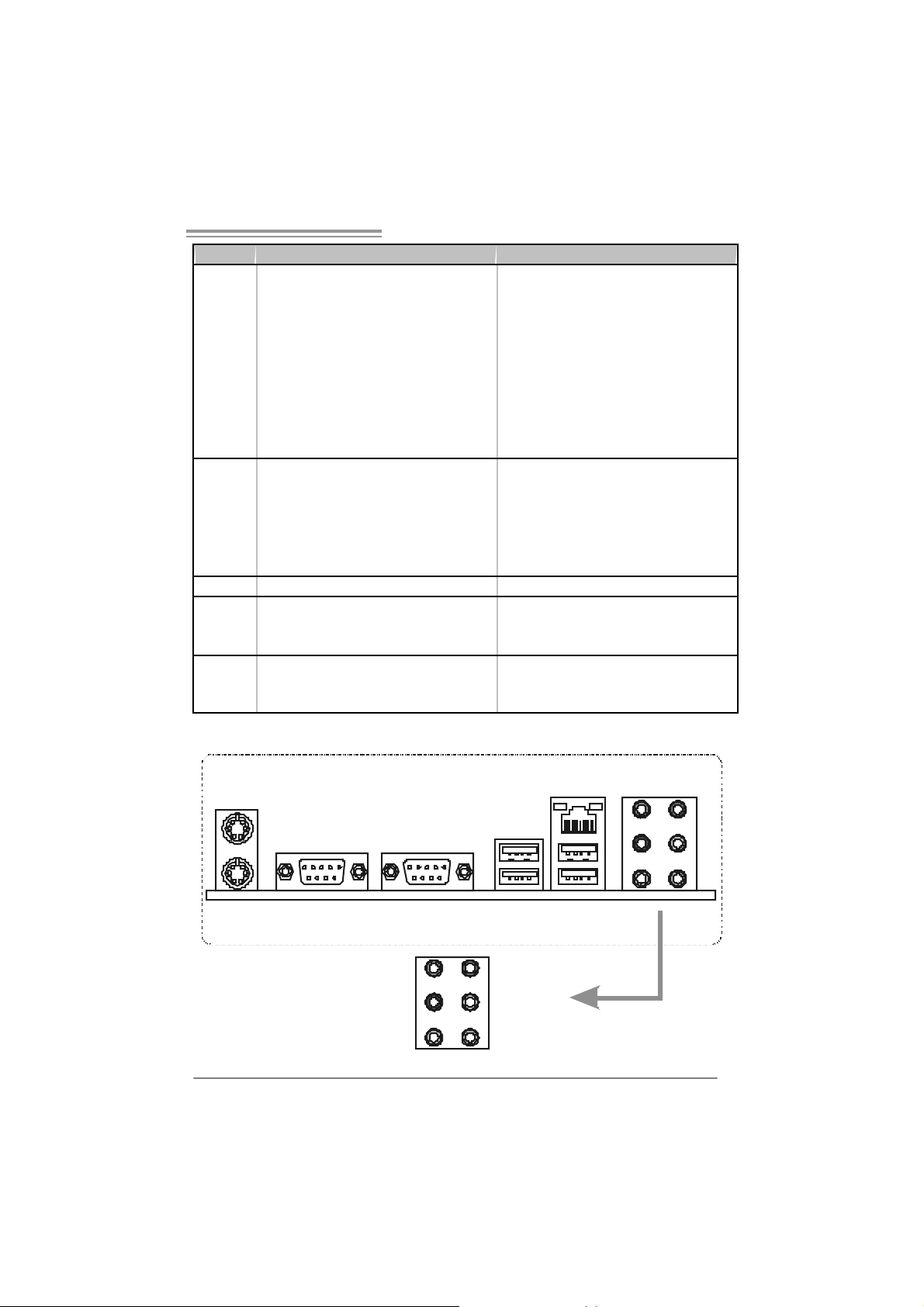
S e ri a l P ort x 1
LAN port x1
USB Port x4
Audio Jack x6
NVIDIA nTunes
NVIDIA firewall (for NF 500 AM 2G only)
RAID 0 / 1 / 0+ 1 support
Windows 2K / XP / VISTA
Biostar Reserves the right to add or remove
support for any OS With or without notice.
PS/2 Keyboard x1
PS/2 Mouse x1
S e ri a l P ort x 1
LAN port x1
USB Port x4
Audio Jack x6
NVIDIA nTunes
NVIDIA firewall
RAID 0 / 1 / 0+ 1 / 5 support
Windows 2K / XP / VISTA
Biostar Reserves the right to add or remove
support for any OS With or without notice.
1.4 REAR PANEL CONNECTORS
PS/2
Mouse
P S /2
Keyboard
COM1 COM2
(optional)
Center
Rear
Side
Line In
Line Out
Mic In
LAN
USBX2USBX2
3
Motherboard Manual
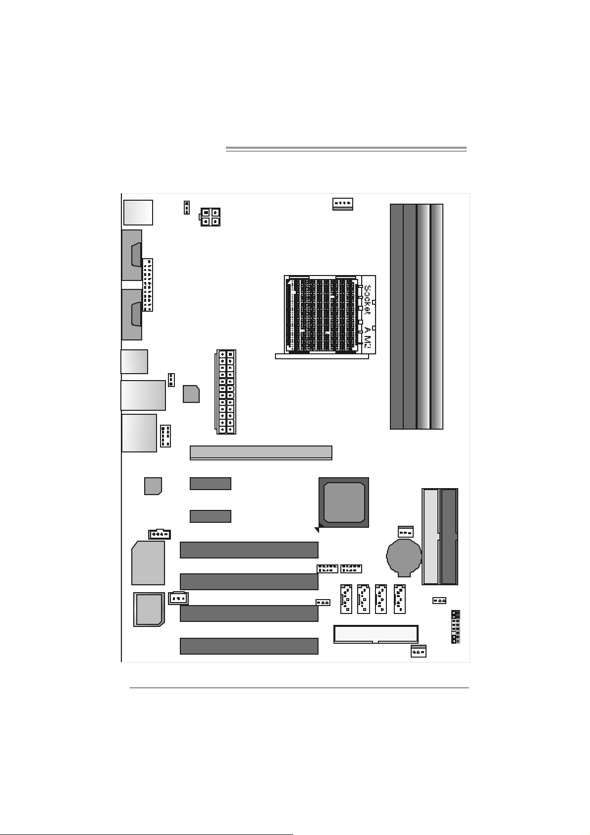
1.5 MOTHERBOARD LAYOUT FOR NF500 AM2L / NF500
AM2G
JCFAN1
JKBMS1
JCOM1
(optional)
JCOM2
JPRNT 1
JKBMSV1
JATXPWR2
JATXPWR1
DIM MA1
DIM MB1
DIM MA2
DIM MB2
JUSB1
JUSBLAN1
JAUDI O2
4
J AUDIO F 1
Codec
JC DIN1
Super I / O
BIOS
Note: represents the 1■
J USBV1
LAN
PEX1_1
PEX1_2
JSPDIF_ OUT1
PCI1
PCI2
PCI3
PCI4
PEX16
st
pin.
nVID IA
nForce500
JUSB2 JUSB3
JUSBV2
JN FAN1
IDE2
IDE1
BAT1
JSATA2JSATA1
FDD1
J SATA4JSATA3
JCMOS1
JPANEL1
JSF AN1
NF500 AM2G / NF500 AM2L / NF500U AM2G
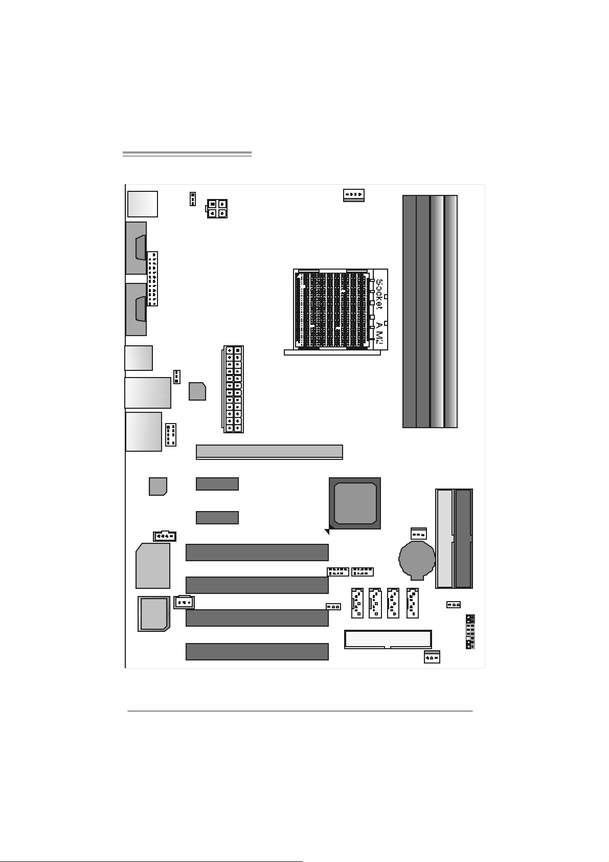
1.6 MOTHERBOARD LAYOUT FOR NF500U AM2G
JCFAN1
JKBMS1
JCOM1
(optional)
JCOM2
JKBMSV1
JATXPWR2
JPRNT 1
JATXPWR1
DIM MA1
DIM MB1
DIM MB2
DIM MA2
JUSB1
J USBV1
JUSBLAN1
JAUDI O2
J AUDIO F 1
Codec
JC DIN1
Super I / O
BIOS
Note: represents the 1■
LAN
PEX1_1
PEX1_2
JSPDIF_ OUT1
PCI1
PCI2
PCI3
PCI4
PEX16
st
pin.
nVID IA
nForce500
Ultra
JUSB2 JUSB3
JUSBV2
JN FAN1
IDE2
IDE1
BAT1
JSATA2JSATA1
FDD1
J SATA4JSATA3
JCMOS1
JPANEL1
JSF AN1
5
Motherboard Manual
CHAPTER 2: HARDWARE INSTALLATION
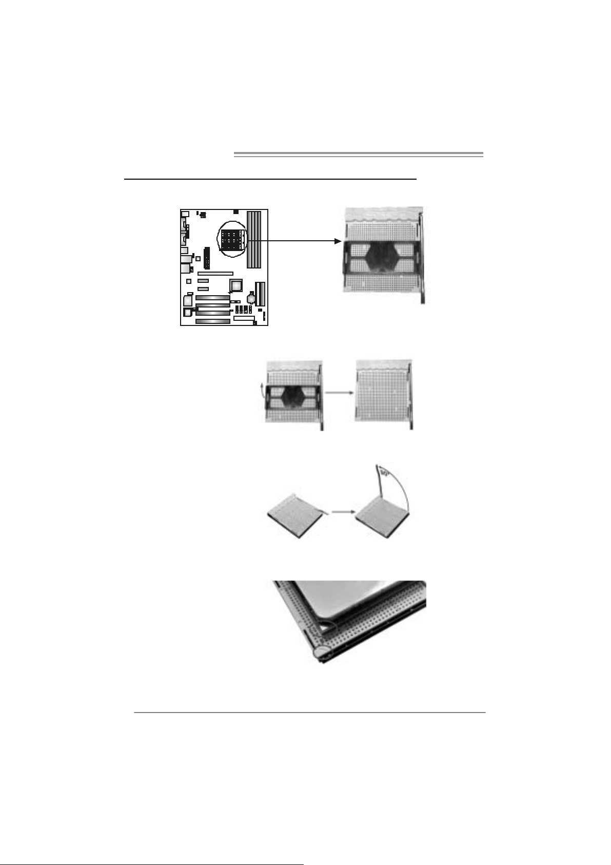
2.1 INSTALLING CEN TRAL PROCESSING UNIT (CPU)
Step 1: Remove the socket protection cap.
Step 2: Pull the lever toward direction A from the socket and then raise the
lever up to a 90-degree angle.
Step 3: Look for the white triangle on socket, and the gold triangle on
CPU should point towards this white triangle. The CPU will fit only
in the correct orientation.
6

NF500 AM2G / NF500 AM2L / NF500U AM2G
Step 4: Hold the CPU down firmly, and then close the lever toward direct
B to complete the installation.
Step 5: Put the CPU Fan on the CPU and buckle it. Connect the CPU
FAN power cable to the JCFAN1. This completes the installation.
7
Motherboard Manual
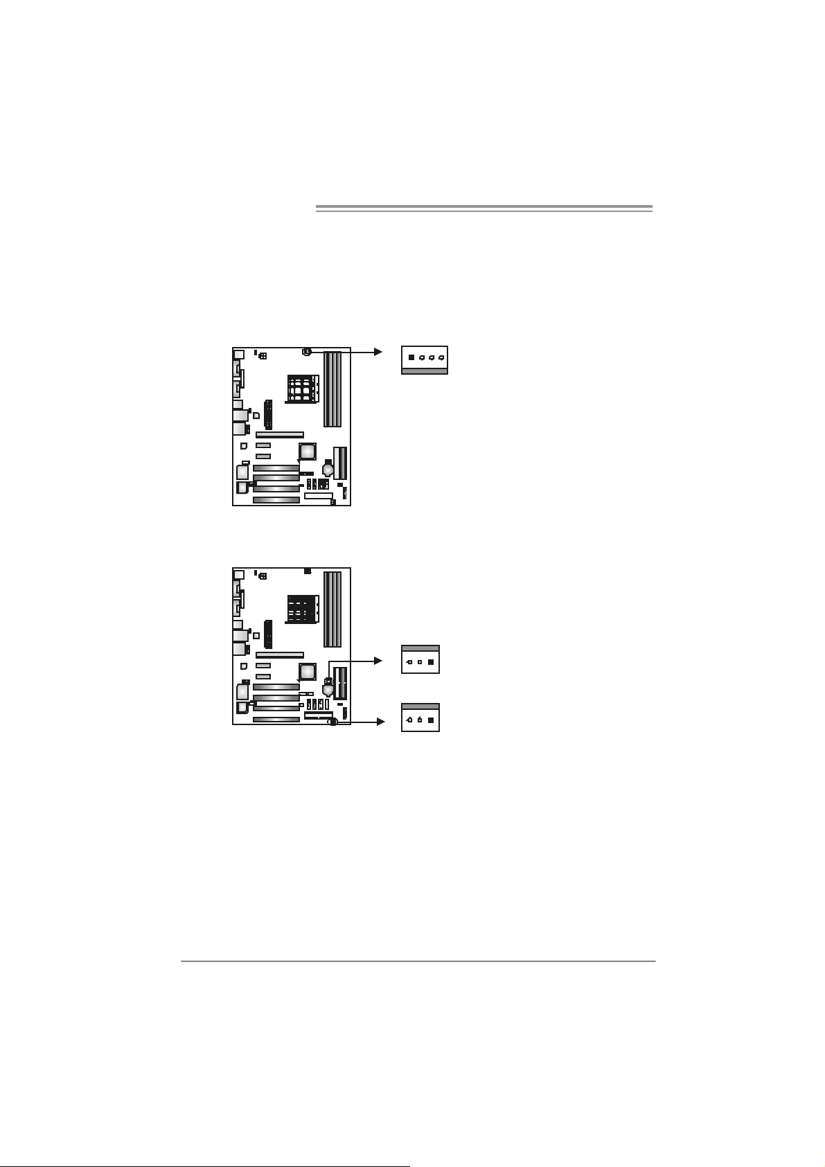
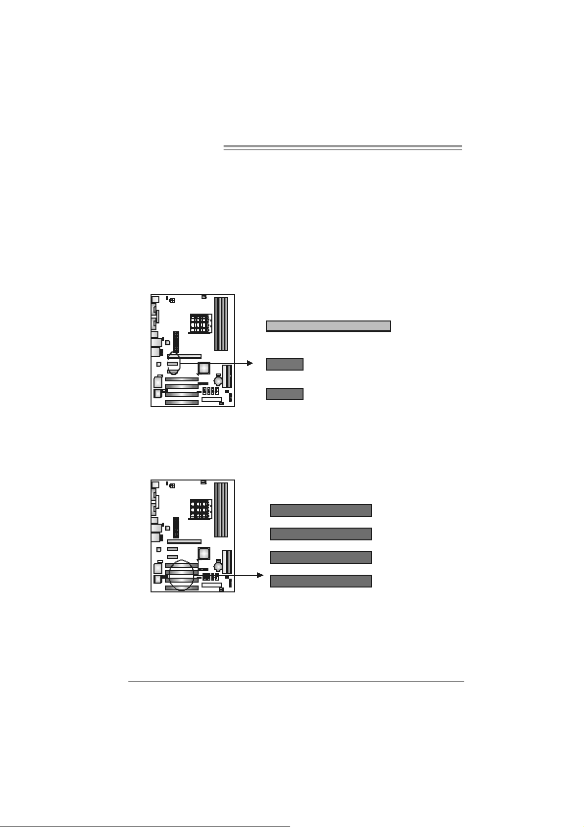
2.2 FAN HEADERS
These fan headers support cooling-fans built in the computer. The fan
cable and connector may be different according to the fan manufacturer.
Connect the fan cable to the connector while matching the black wire to
pin#1.
JCFAN1: CPU Fan Header
JCFAN1
14
JSFAN1 : System Fan Head er
JNFAN1: North Bri dge Fan Heade r
1133
JNFAN1
Pin
1 Ground
2 +12V
3
4 Smart Fan
Pin
1 Ground
2 +12V
3 FAN RPM rate
Assignment
FAN RPM rate
sense
Control (By Fan)
Assignment
sense
JSFAN1
Note:
The J SFAN 1 an d JNF AN 1 s upport 3-pin hea d c onn ect or . When c onnec ti ng with wires
ont o co nnec tors, pl eas e note th at t he r e d wire is th e pos iti ve a nd s hould be c onn ec t ed to
pin#2, a nd th e bl ac k wire is Gr ound and s hould b e c onnect ed to GN D .
8
NF500 AM2G / NF500 AM2L / NF500U AM2G
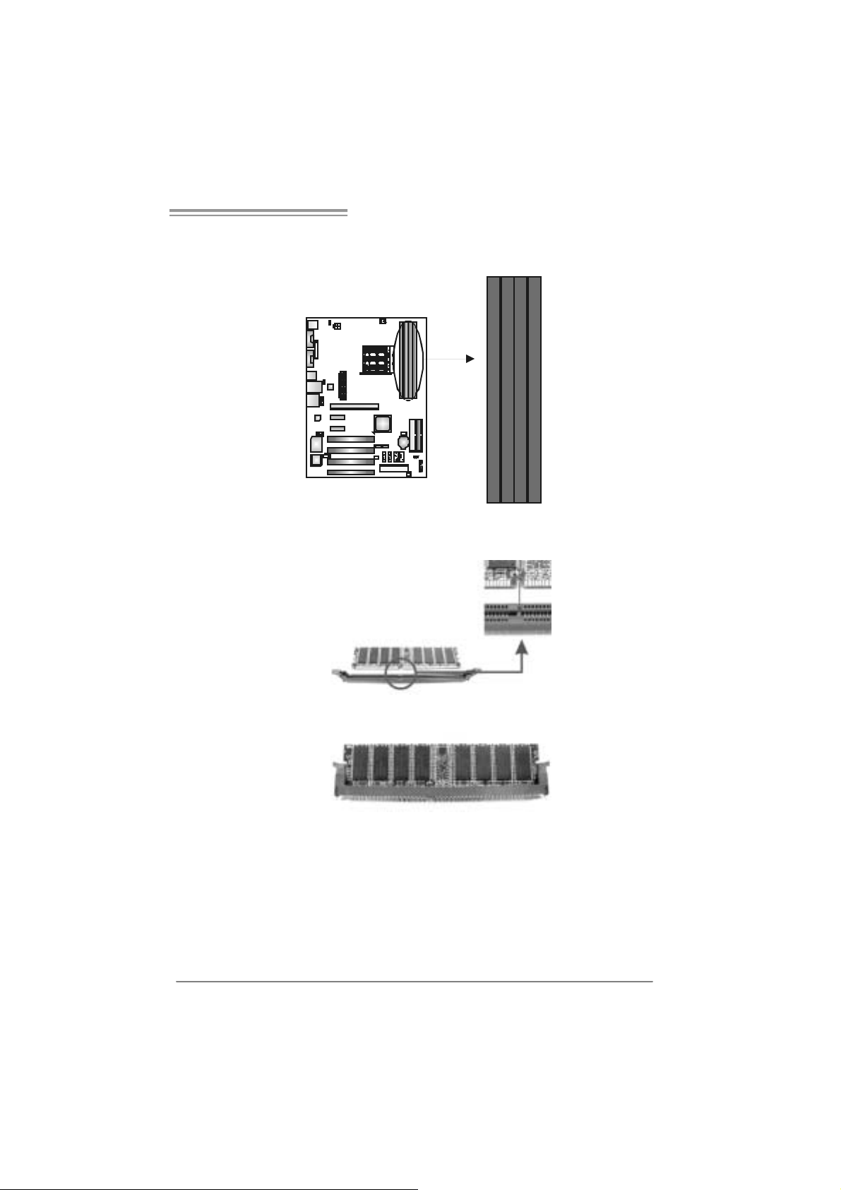
2.3 INSTALLING SYSTEM MEMORY
A. Memory Modu le s
DIMMA1
DIMMB1
DIMMA2
DIMMB2
1. Unlock a DIMM slot by pressing the retaining clips outward. Align a
DIMM on the slot such that the notch on the DIMM matches the
break on the Slot.
2. Insert the DIMM vertically and firmly into the slot until the retaining
chip snap back in place and the DIMM is properly seated.
9
Motherboard Manual
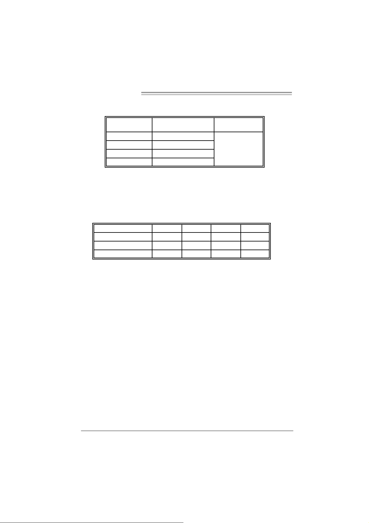
B. Memory Capacity
DI MM Socket
Location
DIMMA1 256MB/512MB/1024MB
DIMMB1 256MB/512MB/1024MB
DIMMA2 256MB/512MB/1024MB
DIMMB2 256MB/512MB/1024MB
DDR Module
To t al Memo r y
Size
Max is 4 GB.
C. Dual Channel Memory installatio n
To trigger the Dual Channel f unction of the motherboard, the memory module
must meet the following requirements:
Install memory module of the same density in pairs, shown in t he f ollowing
table.
Du al Channel Statu s
Enabled O O X X
Enabled X X O O
Enabled O O O O
(O means memory installed, X means memory not installed.)
The DRAM bus width of the memory module must be the same (x8 or
x16)
DIMMA1
DIMMB1 DIMMA2 DIMMB2
10
NF500 AM2G / NF500 AM2L / NF500U AM2G
2.4 CONNECTORS AND SLOTS
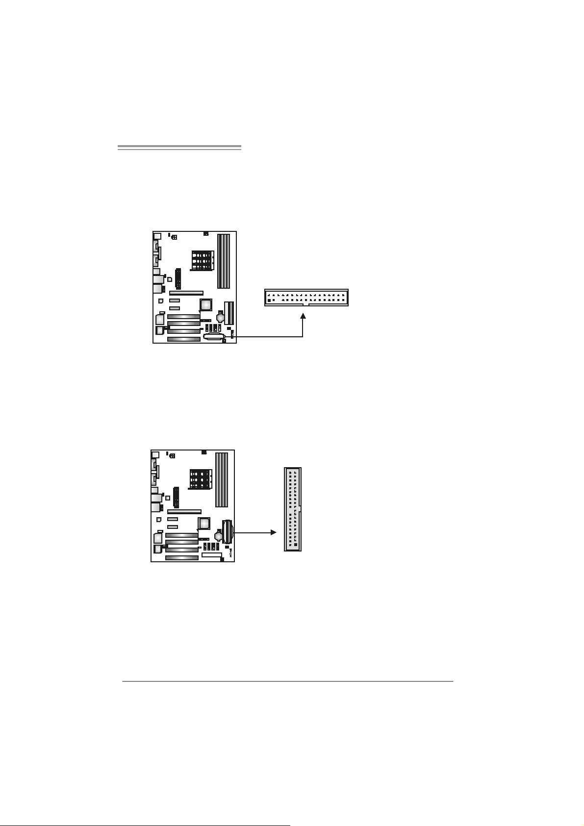
FDD1: Flo ppy Disk Connec tor
The motherboard prov ides a standard floppy disk connector that supports 360K,
720K, 1.2M, 1.44M and 2.88M f loppy disk ty pes. This connector supports the
prov ided f loppy drive ribbon cables.
IDE1/IDE2 : Har d Di sk Connectors
The motherboard has a 32-bit Enhanced PCI IDE Controller that prov ides PIO
Mode 0~4, Bus Master, and Ultra DMA 33/66/100/133 f unctionality. It has two
HDD connectors IDE1 (primary) and IDE2 (secondary).
The IDE connectors can connect a master and a slav e driv e, so you can
connect up to four hard disk drives. The f irst hard drive should always be
connected to IDE1.
2
1
21
3
4
33
3940
IDE2IDE 1
11
Motherboard Manual
PEX16: PCI-Express x16 Slot
- PCI-Ex press 1.0a compliant.
- Maximum theoretical realized bandwidth of 4GB/s simultaneously per
direction, for an aggregate of 8GB/s totally.
PEX1_1/PEX1_2: PCI-Express x1 slots
- PCI-Ex press 1.0a compliant.
- Data transfer bandwidth up to 250MB/s per direction; 500MB/s in total.
- PCI-Ex press supports a raw bit-rate of 2.5Gb/s on the data pins.
- 2X bandwidth ov er the traditional PCI architecture.
PEX16
PEX1_1
PEX1_2
PCI1~PCI4: Peripheral Component Interconnect Slo ts
This motherboard is equipped with 4 standard PCI slots. PCI stands f or
Peripheral Component Interconnect, and it is a bus standard for expansion
cards. This PCI slot is designated as 32 bits.
12
PCI1
PCI2
PCI3
PCI4
NF500 AM2G / NF500 AM2L / NF500U AM2G
_
CHAPTER 3: HEADERS & JUMPERS SETUP
3.1 HOW TO SET UP JUMPERS
The illustration shows how to set up jumpers. When the jumper cap is
placed on pins, the jumper is “close”, if not, that means the jumper is
“open”.
Pin opened Pin closed Pin1-2 closed
3.2 DETAIL SETT INGS
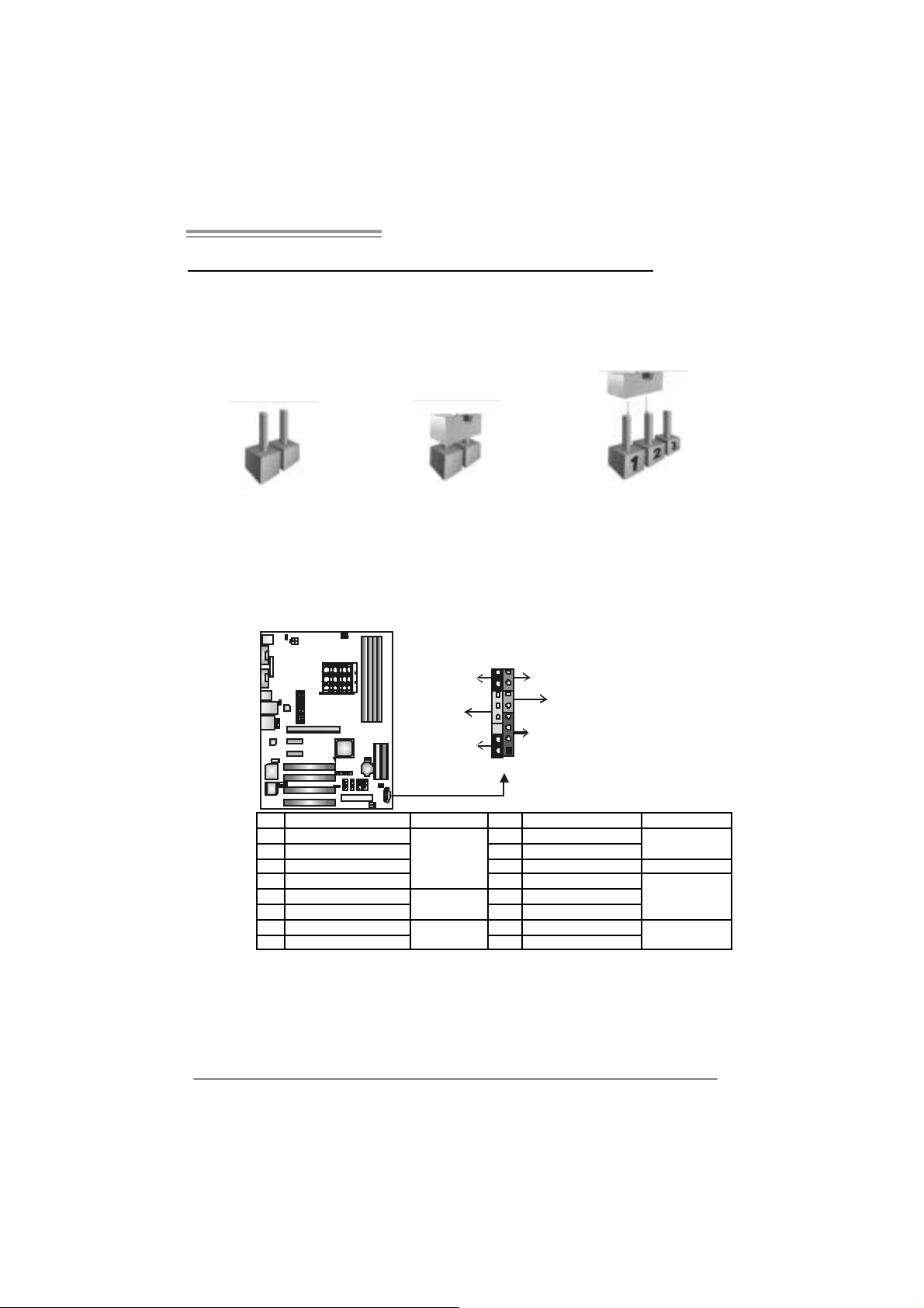
JPANEL1: Front Panel Header
This 16-pin connector includes Power-on, Reset, HDD LED, Power LED, Sleep
button and speaker connection. It allows user to connect the PC case’s f ront
panel switch functions.
16
8
-
++
9
RST
HLED
+
SP K
1
PWR
On/Off
LED
SLP
Pin Assignment Functio n Pin Assignment Function
1 +5V 9 Sleep control
2 N/A 10 Ground
3 N/A 11 N/A N/A
4 Speaker
5 HDD LED (+) 13 Power LED (+)
6 HDD LED (-)
7 Ground 15 Power button
8 Reset control
Speaker
Connector
Hard drive
LED
Reset button
12 P ower LE D (+ )
14 P ower LE D (-)
16 Ground
Sleep button
Power LED
Power-on button
13
Motherboard Manual
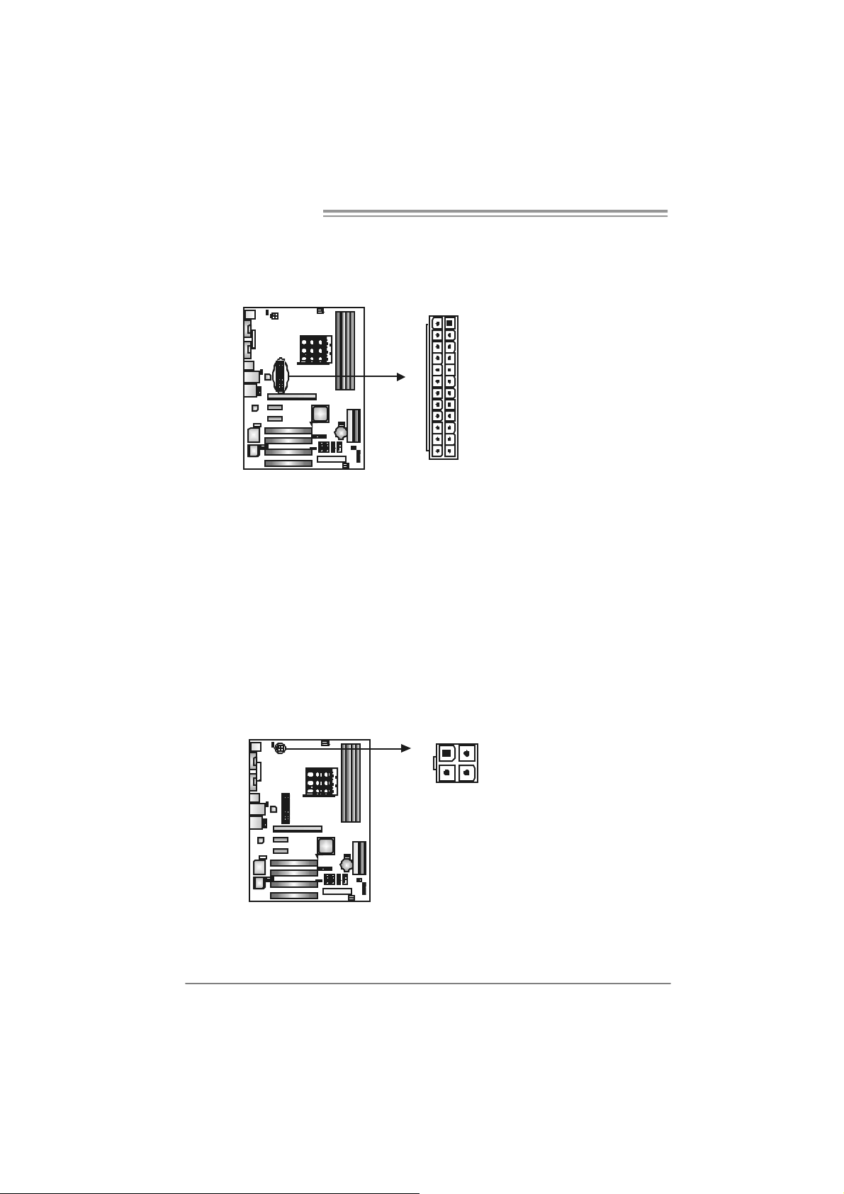
JATXPWR1: ATX Powe r So u rce Conne ctor
This connector allows user to connect 24-pin power c onnector on the ATX
power supply.
Pin Assignment Pin Assignment
13 +3.3V 1 + 3.3V
14 -12V 2 +3.3V
15 Gr oun d 3 Gr oun d
16 PS_ON 4 +5V
17 Gr oun d 5 Gr oun d
18 Gr oun d 6 +5V
19 Gr oun d 7 Gr oun d
20 NC 8 PW_ OK
21 +5V 9 Stand b y Volt age+5V
22 +5V 10 +12V
23 +5V 11 +12V
24 Gr oun d 12 +3.3V
113
1224
JATXPWR2: ATX Powe r So u rce Conne ctor
By connecting this connector, it will provide +12V to CPU power circuit.
14
1
4
32
Pin
Assignment
1 +12V
2 +12V
3 Ground
4 Ground
NF500 AM2G / NF500 AM2L / NF500U AM2G
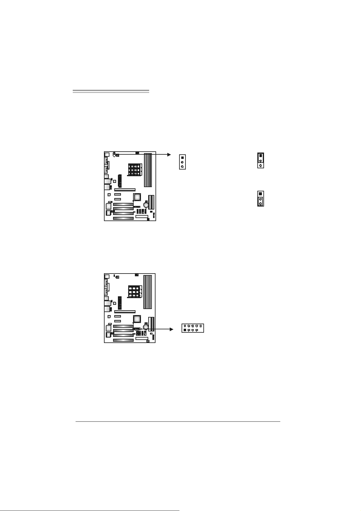
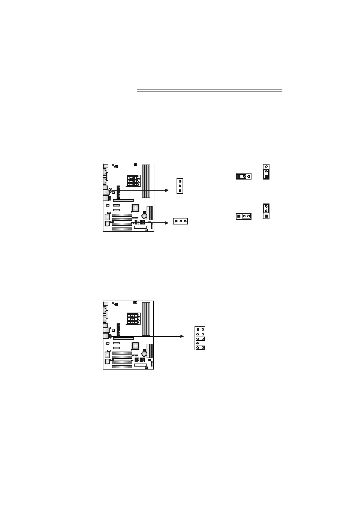
JKBMSV1: Power Source Selection Heade rs for Keyboard/Mouse
Pin 1-2 C lose:
JKBMSV1: +5V for PS/2 key board and mouse。
Pin 2-3 C lose:
JKBMSV1: PS/2 keyboard and mouse are powered with +5V standby
v oltage.
1
3
1
3
Pin 1-2 close
1
3
Pin 2-3 close
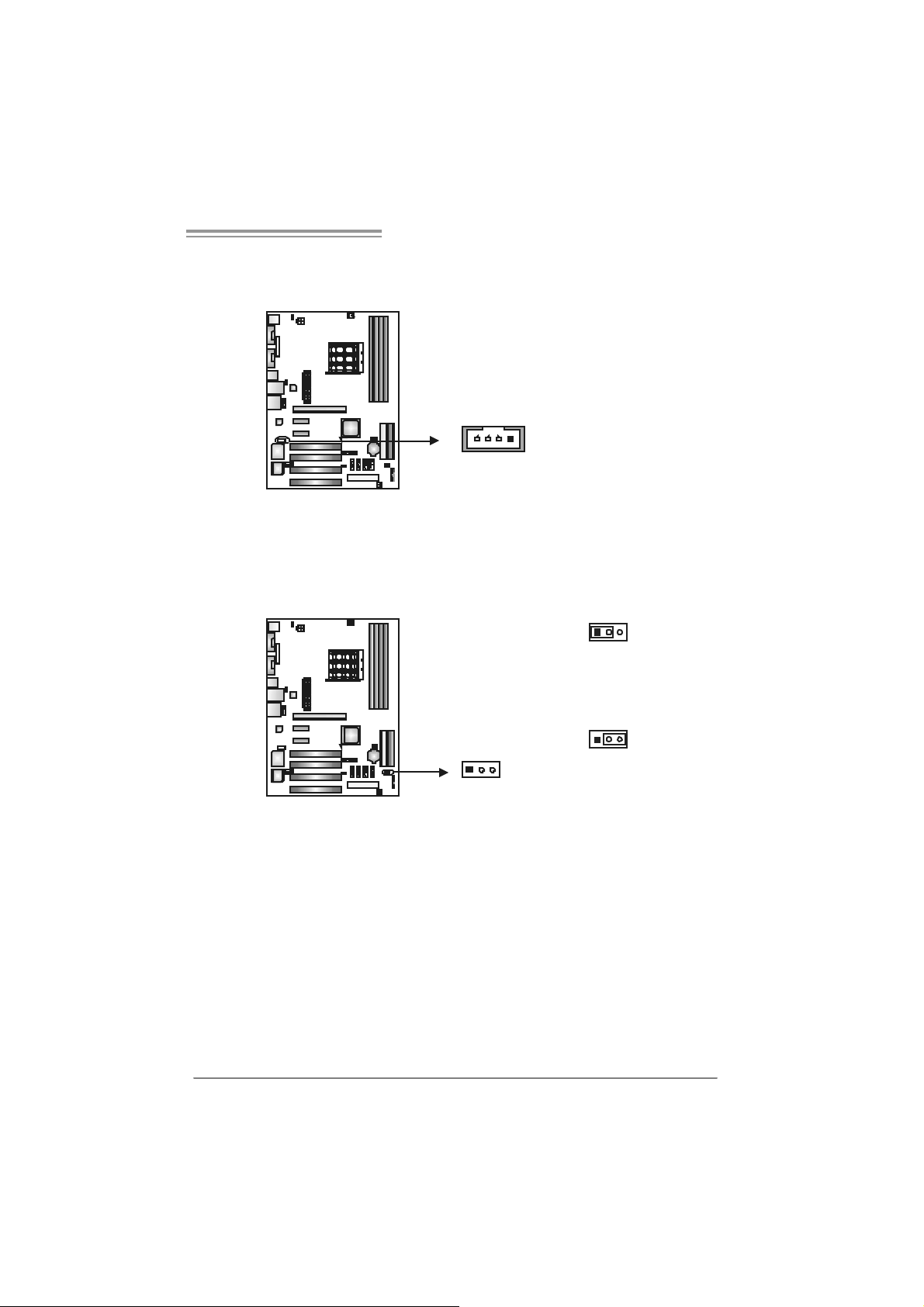
JUSB2/JUSB3: Heade rs for USB 2.0 Ports at Front Panel
This header allows user to connect additional USB cable on the PC f ront panel,
and also can be connected with internal USB devices, like USB card reader.
USB2 / USB3
Pin Assignment
1 +5V (fused)
2 +5V (fused)
3 USB-
4 USB5 USB+
JUSB2 JU SB3
2
1
10
9
6 USB+
7 Ground
8 Ground
9 Key
10 NC
15
Motherboard Manual
JU SB V1/JUSB V2: Powe r Source H eaders for USB P orts
Pin 1-2 C lose:
JUSBV1: +5V for USB ports at JUSBLAN1.
JUSBV2: +5V for USB ports at f ront panel (JUSB2/JUSB3).
Pin 2-3 C lose:
JUSBV1: USB ports at JUSBLAN1 are powered by +5V standby voltage.
JUSBV2: USB ports at front panel (JUSB2/JUSB3) are powered by +5V
standby v oltage.
3
JUSBV1
Pin 1-2 close
3
31
1
3
3
1
113
JUSBV2
1
Pin 2-3 close
Note:
In ord er to s up por t this f unctio n “P ower- On s yst em vi a U SB de vic e,” “ JU SBV1 / JUSB V2”
jumper ca p should be pl ac ed on Pi n 2-3 in di vidu al l y.
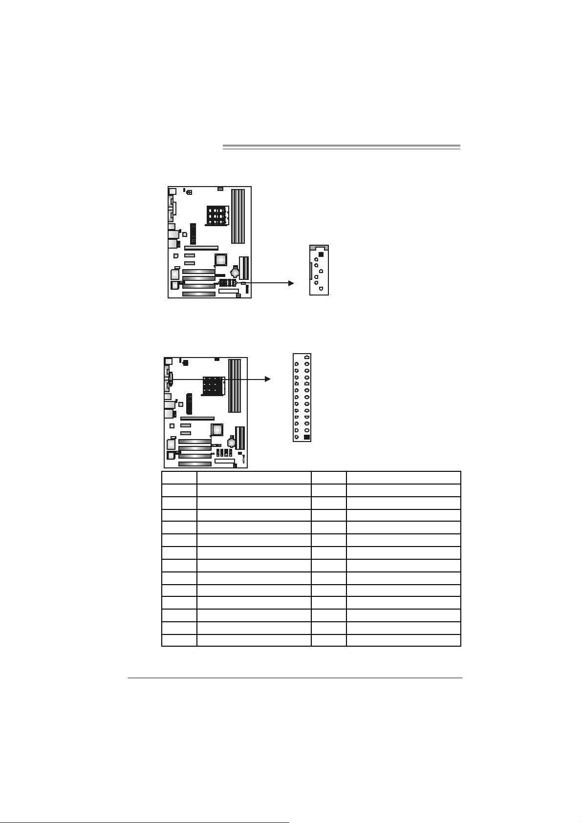
JAUDIOF1: Fron t Panel Au dio Heade r
This header allows user to connect t he front audio output cable with the PC f ront
panel. It will disable the output on back panel audio c onnectors.
Pin Assignment
1 Mic Left in
2 Ground
1
9210
3 Mic Right in
4 GPIO
5 Right line in
6 Jack Sense
7 Front Sense
8 Key
9 Left line in
10 Jack Sense
16
NF500 AM2G / NF500 AM2L / NF500U AM2G
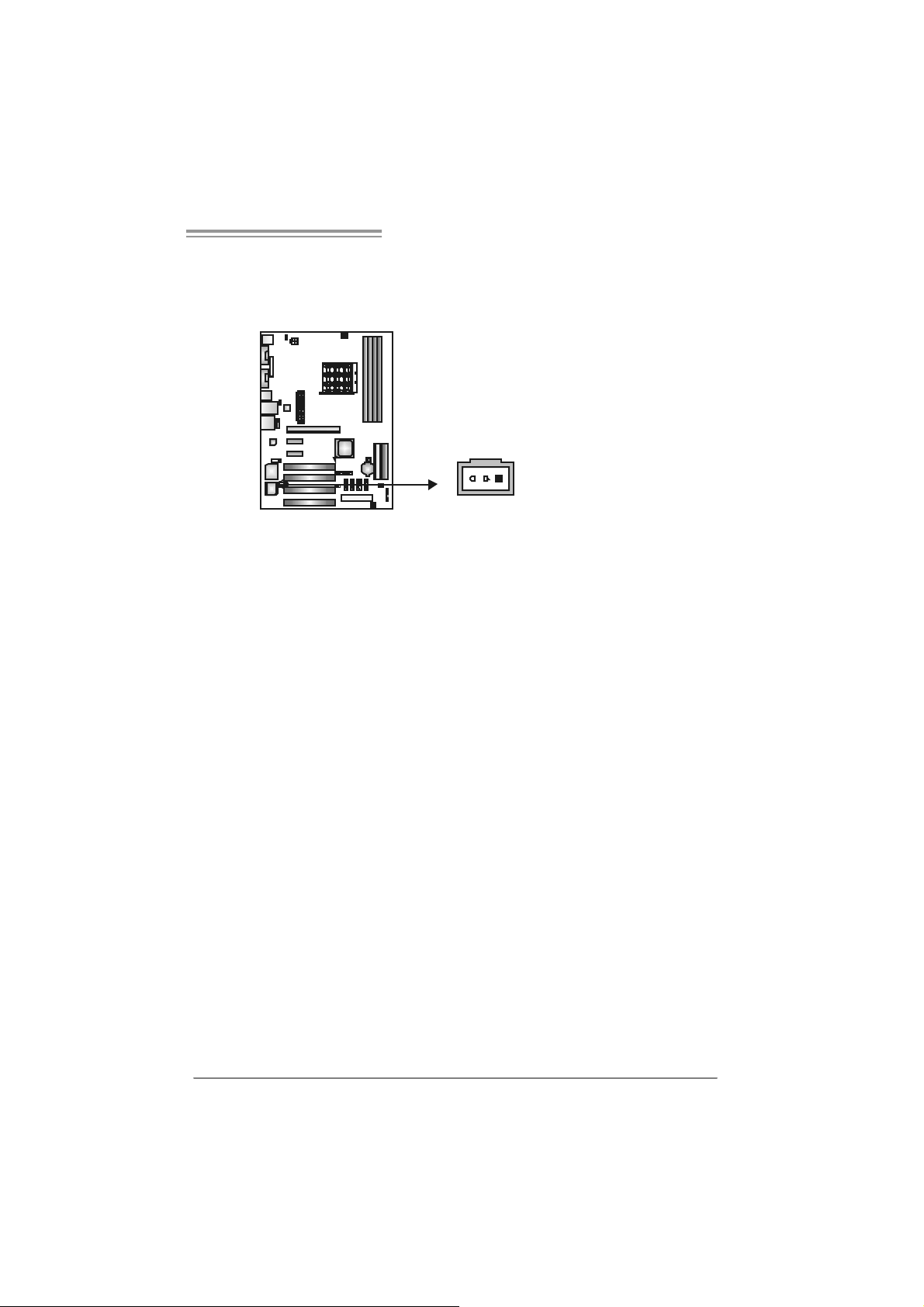
JCDIN1: CD-ROM Aud io-in Connector
This connector allows user to connect the audio source f rom the v ariaty dev ices,
like CD-ROM, DVD-ROM, PCI sound card, PCI TV turner card etc..
Assignment
Pin
1 Left Channel Input
2 Ground
14
JCMOS 1 : C lear CMO S He ader
By placing the jumper on pin2-3, it allows user to restore the BIOS saf e setting
and the CMOS data, please carefully f ollow the procedures to avoid damaging
the motherboard.
3 Ground
4 Right Channel Input
13
Pin 1-2 Close:
Normal Operation (default).
13
13
Pin 2-3 Close:
Clear CMOS data.
※ Clear CMOS Procedures:
1. Remov e AC power line.
2. Set the jumper to “Pin 2-3 close”.
3. Wait f or f ive seconds.
4. Set the jumper to “Pin 1-2 close”.
5. Power on the AC.
6. Reset y our desired pas sword or c lear the CMOS data.
17
Motherboard Manual
JSATA1~JS ATA4: Serial ATA Connecto rs
The motherboard has a PCI to SATA Controller with 4 channels SATA interf ace.
JS ATA1 J S ATA2 J SATA3 JS ATA 4
JPRNT1: Printer Port Connector
This header allows you to connector printer on the PC.
25
Pin
Assignment
1 Ground
2 TX +
3 TX -
1
4
7
4 Ground
5 RX6 RX+
7 Ground
18
12
Pin Assignment Pin Assignment
1 -Strobe 14 Ground
2 -ALF 15 Data 6
3 Data 0 16 Ground
4 -Error 17 Data 7
5 Data 1 18 Ground
6 -Init 19 -ACK
7 Data 2 20 Ground
8 -Scltin 21 Busy
9 Data 3 22 Ground
10 Ground 23 PE
11 Data 4 24 Ground
12 Ground 25 SCLT
13 Data 5 26 Key
NF500 AM2G / NF500 AM2L / NF500U AM2G
JSPDI F_O UT1: Di gital Audio-out Conne ctor
This connector allows user to connect the PCI bracket SPDIF output header.
Pin
Assignment
1 +5V
2 SPDIF_OUT
3 Ground
13
19
Motherboard Manual
CHAPTER 4: NVIDIA RAID FUNCTIONS
4.1 OPERATION SYSTEM
z Supports Windows XP Home/Prof essional Edition, and Windows 2000 Prof essional.
4.2 RAID ARRAYS
NVRAID supports the following ty pes of RAID arrays:
RAID 0: RAID 0 defines a disk striping scheme that improves disk read and write times for
many applications.
RAID 1: RAID 1 defines t echniques for mirrori ng data.
RAID 0+1: RAID 0+1 combines the techniques used in RAID 0 and RAID 1.
4.3 HOW RAID WORKS
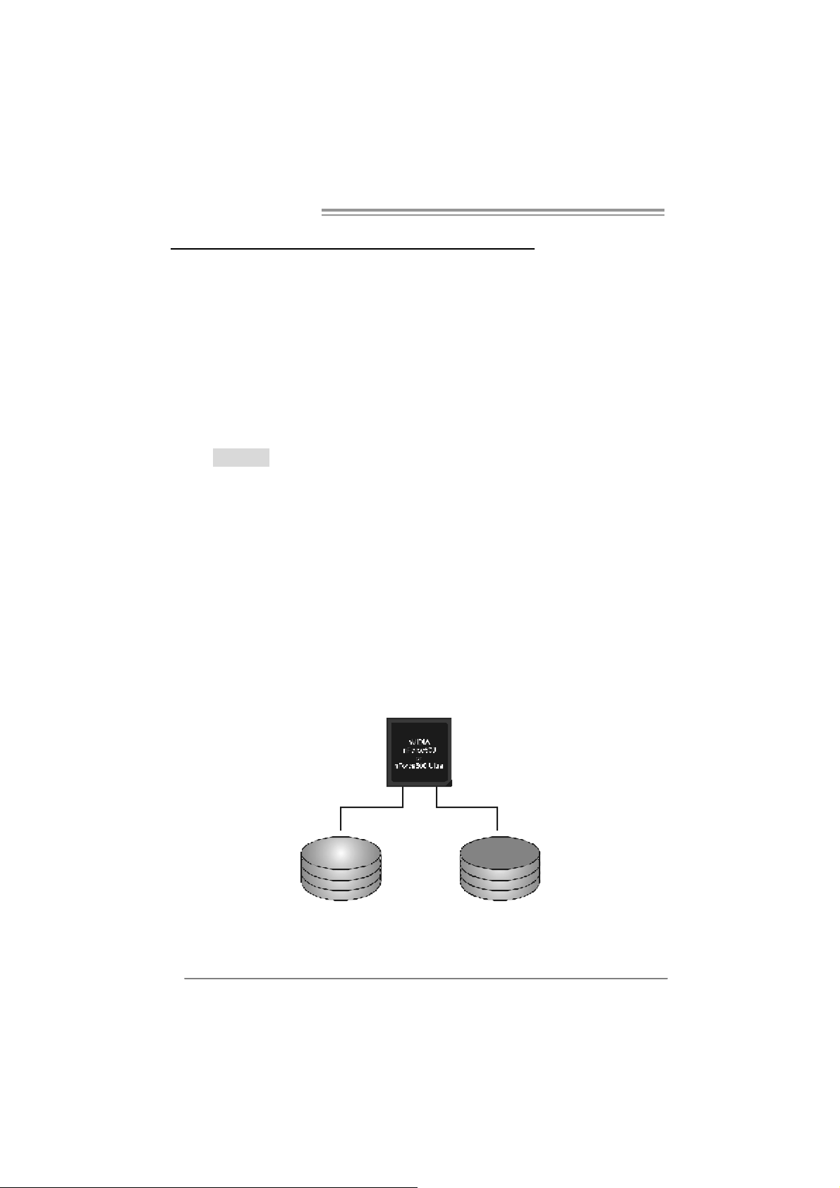
RAID 0:
The controller “stripes” data across multiple drives in a RAID 0 array system. It breaks
up a large file into smaller blocks and performs disk reads and writes across multiple
drives in parallel. The size of each block is determined by the stripe size parameter,
which you set during the creation of the RAID set based on the system environment. This
technique reduces overall disk access t ime and offers high bandwidth.
Fea tures and Be nefits
Drives: Minimum 1, and maximum is up to 6 or 8. Depending on the
platform.
Uses: Intended for non-critical data requiring high data throughput, or any
env ironment that does not require fault tolerance.
Benefits: prov ides increased data throughput, especially f or large files. No
capacity loss penalty for parity.
Drawbacks: Does not deliver any fault tolerance. If any drive in the array
f ails, all data is lost.
Faul t Tolerance : No.
20
Blo c k 1
Block 3
Block 5
Block 2
Block 4
Block 6
NF500 AM2G / NF500 AM2L / NF500U AM2G
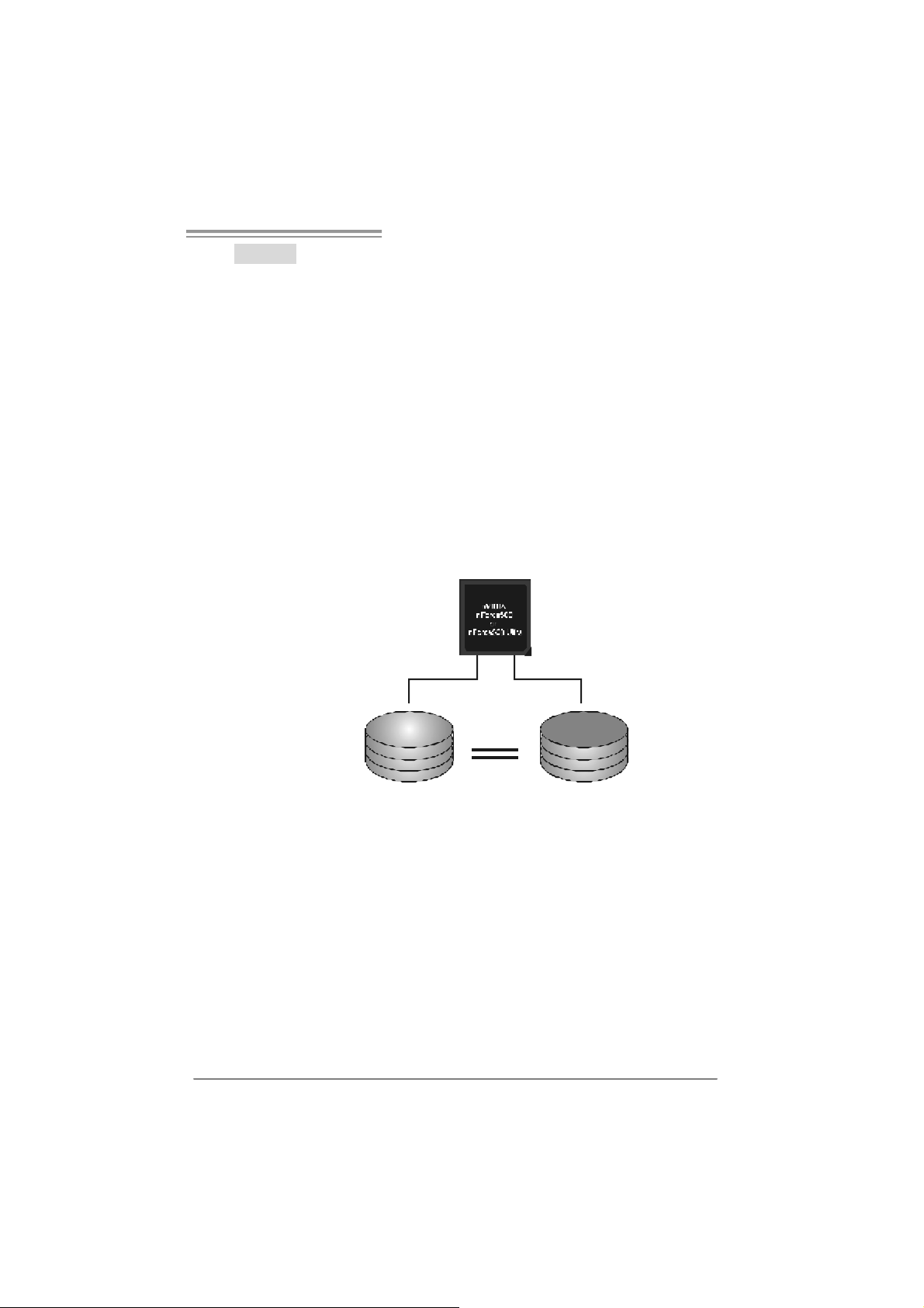
RAID 1:
Every read and write is actually carried out in parallel across 2 disk drives in a RA ID 1
array system. The mirrored (backup) copy of the data can reside on the same disk or on
a second redundant drive in the array. RAID 1 provides a hot-standby copy of data if
the active volume or driv e is co rrupted or beco mes u navailable because of a hardware
failure.
RAID techniques can be applied for high-availability solutions, or as a form of
automatic backup that eliminates tedious manual backups to more expensive and less
reliable media.
Fea tures and Be nefits
Drives: Minimum 2, and maximum is 2.
Uses: RAID 1 is ideal f or small databases or any other application that
requires f ault tolerance and minimal capacity.
Benefits: Prov ides 100% data redundancy. Should one driv e f ail, the
controller switches to the other drive.
Drawbacks: Requires 2 driv es for the storage space of one drive.
Perf ormance is impaired during driv e rebuilds.
Fault To le rance : Yes.
Blo c k 1
Block 2
Block 3
Block 1
Block 2
Block 3
21
Motherboard Manual
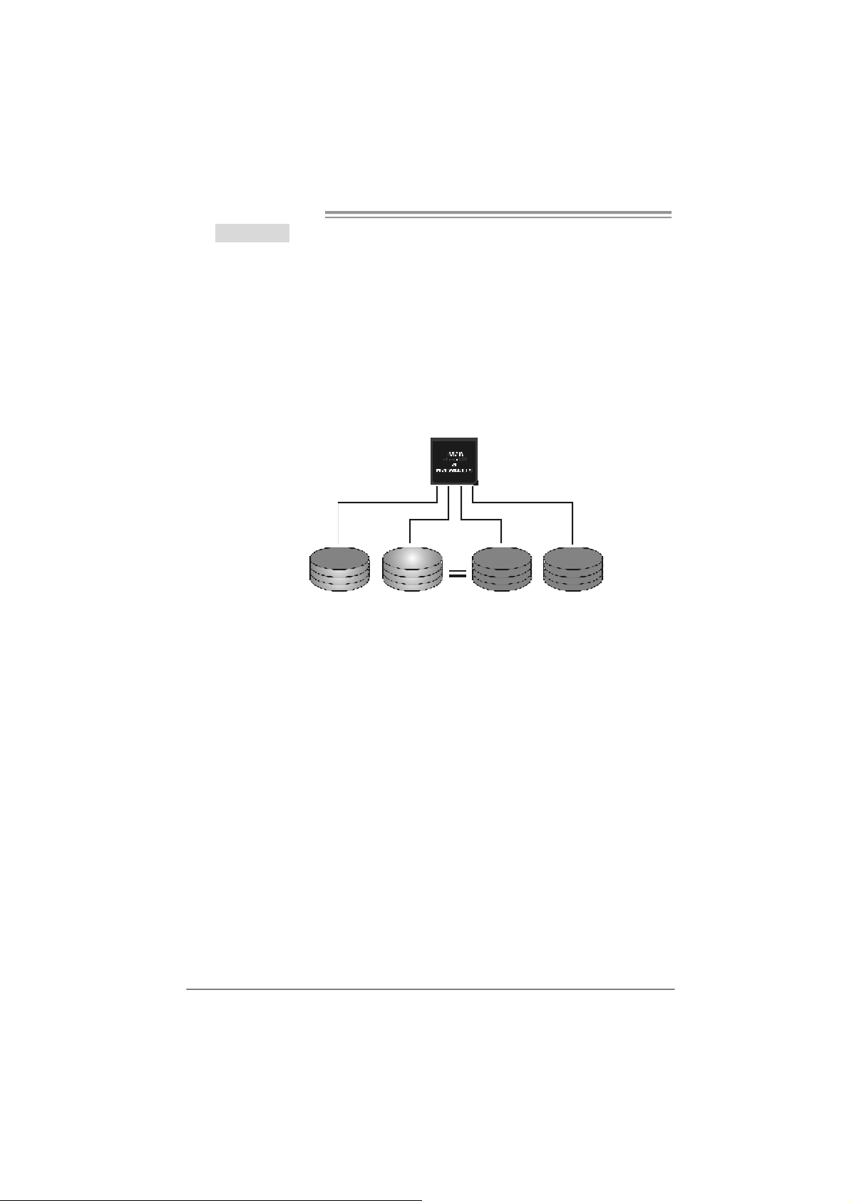
RAID 0+1:
RAID 0 drives can be mirrored using RAID 1 techniques. Resulting in a RAID 0+1
solution for improved performance plus resiliency.
Fea tures and Be nefits
- Drives: Minimum 4, and maximum is 6 or 8, depending on the platform.
- Benefits: Optimizes for both fault tolerance and perf ormance, allowing for
automatic redundancy. May be simultaneously used with other RAID
lev els in an array, and allows f or spare disks.
- Drawbacks: Requires twice the av ailable disk space f or data redundancy,
the same as RAID level 1.
- Faul t Tolerance: Yes.
Block 1
Block 3
Block 5
Block 2
Block 4
Block 6
Block 1
Block 3
Block 5
Block 2
Block 4
Block 6
22
NF500 AM2G / NF500 AM2L / NF500U AM2G
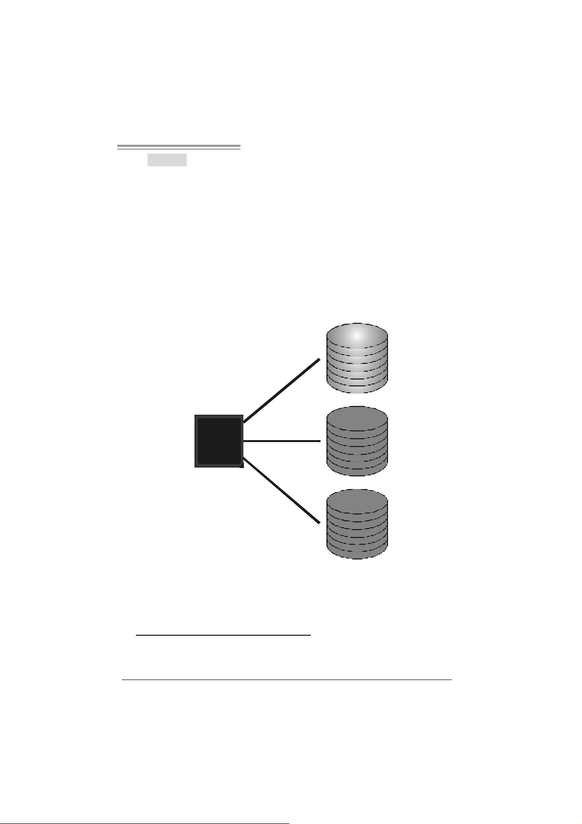
RAID 5:
RAID 5 stripes both data and parity information across three or more drives. It writes
data and pa rit y blo cks across all th e driv es in th e arr ay . F aul t to l er ance is mai nt ain ed
by ensuring that the parity in formation for any given block of data is placed on a
different drive from those used to store the data itself.
Features and Benefits
- Drives: Minim um 3.
- Uses: RAID 5 is recommended for transaction processing and general
purpose service.
- Benefits: An ideal c ombination of good performance, good fault tolerance,
and high capacity and storage efficiency.
- Drawbacks: Individual block data transfer rate same as a single disk.
W ri t e p e rf orm a n c e c a n be CP U i n t e ns iv e.
- Fault To le rance : Yes.
Di s k 1
DATA 1
DATA 3
PA RI TY
DATA 7
DATA 9
PA RI TY
Di s k 2
nVidia
n Forc e500
Ultra
DATA 2
PAR ITY
DATA 5
DATA 8
PAR ITY
DATA 11
Di s k 3
PAR ITY
DATA 4
DATA 6
PAR ITY
DATA 10
DATA 12
※ For more detailed setup information, please refer to the Driver CD, or go to
http://www.nvidia.com/page/pg_20011106217193.htm l to download NVIDIA nForce Tutorial Flash.
23
Motherboard Manual
CHAPTER 5: USEFUL HELP
5.1 DRIVER INSTALLA TION NOTE
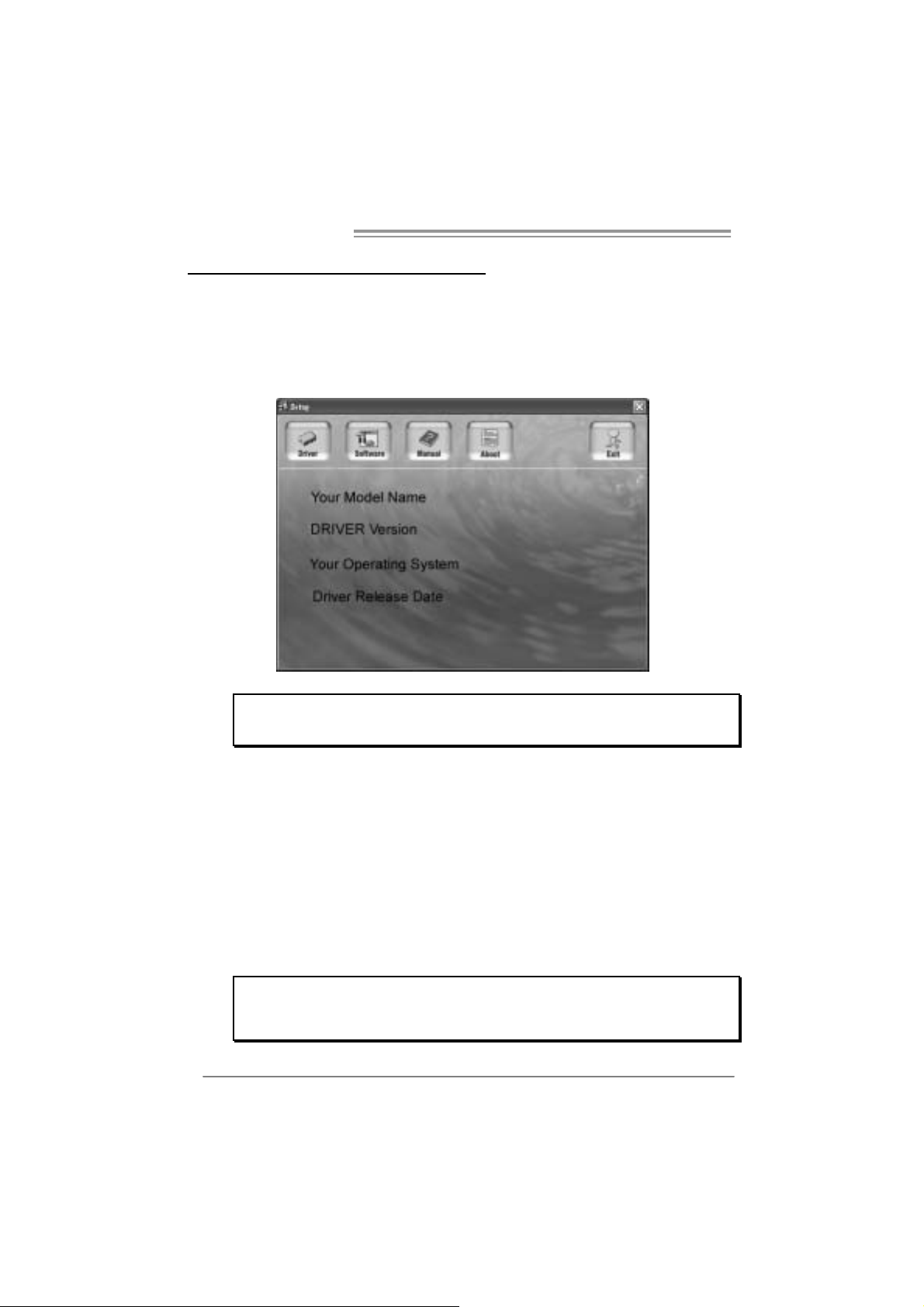
After you installed your operating system, please insert the Fully Setup
Driver CD into your optical drive and install the driver for better system
performance.
You will see the following window after you insert the CD
The setup guide will auto detect your motherboard and operating system .
Note:
If this win do w didn’t sho w up after you ins ert th e Driver CD, ple ase use fi l e br o ws er to
locate and e xecu te th e file SETU P.E XE un der yo ur opti c al drive.
A. Driver Install ation
To install the driver, please click on the Driver icon. The setup guide will
list the compatible driver for your motherboard and operating system.
Click on each device driver to launch the installation program.
B. Software Installation
To install the software, please click on the Software icon. The setup guide
will list the software available for your system, click on each software title
to launch the installation program.
C. Manual
Aside from the paperback manual, we also provide manual in the Driver
CD. Click on the Manual icon to browse for available manual.
Note:
You will need Acrobat Reader to open the manual file. Please download the latest version
of Acrob at Re ad er software fro m
http://www.adobe.com/products/a crobat/readstep2.html
24
NF500 AM2G / NF500 AM2L / NF500U AM2G
5.2 AWARD BIOS BEEP CODE
Beep Sound Meanin g
One long beep followed by two s hort
beeps
High-low siren sound CPU overheated
One Short beep when system boot-up No error found during POST
Long beeps every other second No DRAM detected or install
Video card not found or v ideo card
memory bad
System will shut down automatically
5.3 EXT RA INFORMATION
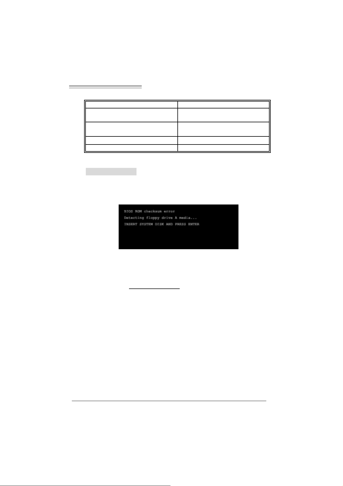
A. BIOS Update
After you fail to update BIOS or BIOS is invaded by virus, the
Boot-Block function will help to restore BIOS. If the following message
is shown after boot-up the system, it means the BIOS contents are
corrupted.
In this Case, please follow the procedure below to restore the BIOS:
1. Make a bootable floppy disk.
2. Download the Flash Utility “AWDFLASH.exe” from the Biostar
website: www.biostar.com.tw
3. Confirm motherboard model and download the respectively BIOS
from Biostar website.
4. Copy “AWDFLASH.exe” and respectively BIOS into floppy disk.
5. Insert the bootable disk into floppy drive and press Enter.
6. System will boot-up to DOS prompt.
7. Type “Awdflash xxxx.bf/ sn/p y/ r” in DOS prompt.
(xxxx means BIOS name.)
8. System will upda te BIOS automatically and restart.
9. T he BIOS has been recovered and will wo rk properl y.
25

Motherboard Manual
B. CPU Overheated
If the system shutdown automatically after power on system for
seconds, that means the CPU protection function has been activated.
When the CPU is over heated, the motherboard will shutdown
automatically to avoid a damage of the CPU, and the system may not
power on again.
In this case, please double check:
1. The CPU cooler surface is placed evenly with the CPU surface.
2. CPU fan is rotated normally.
3. CPU fan speed is fulfilling with the CPU speed.
After confirmed, please follow steps below to relief the CPU protection
function.
1. Remove the power cord from power supply for seconds.
2 . Wa i t f o r se c o nd s.
3. Plug in the power cord and boot up the system.
Or you can:
1. Clear the CMOS data.
(See “Close CMOS Header: JCMOS1” section)
2 . Wa i t f o r se c o nd s.
3. P o we r on the syste m ag ai n.
26
 Loading...