

Page 1

NF500 AM2G / NF500 A M2L / NF500U AM2G
Setup Manual
FCC Inf or m at ion and Copyright
This equipment has been tested and found to comply with the limits of a Class
B digital device, pursuant to Part 15 of the FCC Rules. T hese limits are designed
to provide reasonable protec tion ag ainst ha rmful i nterfe re nce in a residential
installation. T his equipment generates, uses and can radiate radio frequency
energy and, if not ins talled and used in accordance with the instructions, may
cause harmful interference to radio communications. There is no guarantee
that i nter fe rence wil l not occur in a pa rtic u la r ins ta llatio n .
The vendo r ma kes no represe ntatio ns or wa r ra n ties wi th respec t to th e
contents here and specially disclaims any implied warranties of merchantability
o r fi tn es s fo r a ny p u rp os e . F u rt he r t he ve nd o r res e rves t he ri g ht to rev is e th is
publication and to make changes to the c ontents here without obligation to
notify any party beforehand.
D uplic a tion o f this publicat io n , in pa rt o r in wh ol e, is no t allo wed wit ho ut first
obtaining the vendor’s approval in writing.
The content of this user’s manual is subject to be c hanged without notice and
we will not be responsible for any mis takes found in this user’s manual. Al l the
brand and product names are trademarks of their respec tive companies.
Page 2

Table of Contents
Chapter 1: Introduction .............................................1
1.1 Before You Start...................................................................1
1.2 Package Checklist................................................................1
1.3 Motherboard Features..........................................................2
1.4 Rear Panel Connectors.......................................................... 3
1.5 Mot herbo a r d Layo u t for NF5 00 A M2L / NF 500 A M2 G............ 4
1.6 Mo t herbo a r d Layo u t for NF5 00U A M2G................................5
Chapter 2: Hardware Installation ..............................6
2.1 Installing Ce ntral Proce ssing Unit (CPU)................................ 6
2.2 FAN Heade rs........................................................................ 8
2.3 Installing System Memory......................................................9
2.4 Con nectors a nd Slo ts............................................................11
Chapter 3: Headers & Jumpers Setup......................13
3.1 How to Se t u p Ju mper s..........................................................13
3.2 Det ail Settin gs.....................................................................13
Chapter 4: NVIDIA RAID Functions.........................20
4.1 Operation Syste m................................................................20
4.2 Raid Arrays.........................................................................20
4.3 How RA I D Wor k s.................................................................20
Chapter 5: Useful Help ..............................................24
5.1 Driver Instal latio n Note.......................................................24
5.2 Award BIOS Bee p Code........................................................25
5.3 Extra Informati on ................................................................25
5.4 Troubleshooting...................................................................27
Chapter 6: WarpSpeeder™ .......................................28
6.1 Introduction........................................................................28
6.2 System Requirement............................................................28
6.3 Installation.........................................................................29
6.4 WarpSpeede r™....................................................................30
Appendencies: SPEC In Other Language ................36
German................................................................................................36
France..................................................................................................38
Italian..................................................................................................40
Spanish................................................................................................42
Portuguese...........................................................................................44
Polish...................................................................................................46
RUSSIAN...............................................................................................48
ARABIC................................................................................................50
JAPANESE............................................................................................52
Page 3

NF500 AM2G / NF500 AM2L / NF500U AM2G
CHAPTER 1: INTRODUCTION
1.1 BEFORE YOU START
Tha nk you for choosing our pro du ct. Befo re you start ins talling the
mo therboa rd, plea se make su re you follo w the ins tructio ns be lo w:
Prepare a dry and stable working environment with
s uf ficie nt ligh ting .
Always disconnect the computer from power outlet
be fo re ope ra tion.
Be fo re yo u take the mo the rbo a rd ou t f rom a n ti -s ta ti c
bag, ground yourself properly by touching any safely
grounde d ap plian ce, o r use grounded wris t s trap to
remove the static charge.
Avo id tou ch ing the com pone nt s o n mo the rboa rd o r the
rea r side of the boa rd unless ne cessary. Hold the bo ard
on the edge , do not try to be nd o r flex the boa rd.
Do no t lea ve any unfas tened sma ll pa rts inside the
case after installation. Loose parts will cause short
circu its which ma y damage the equipment.
Keep the computer from dangerous area, such as heat
so u rce , humid a ir and water.
1.2 PACKAGE CHECKLIST
FDD Cable X 1
HDD Cable X 1
Se ria l ATA Cab le X 1
Rear I/O Panel for ATX Case X 1
Use r’s Ma nual X 1
Fully Setup Driver CD X 1
USB 2.0 Cable X1 (optional)
S/P DI F ou t Ca ble X 1 (op tiona l)
1
Page 4
Motherboard Manual
y
r
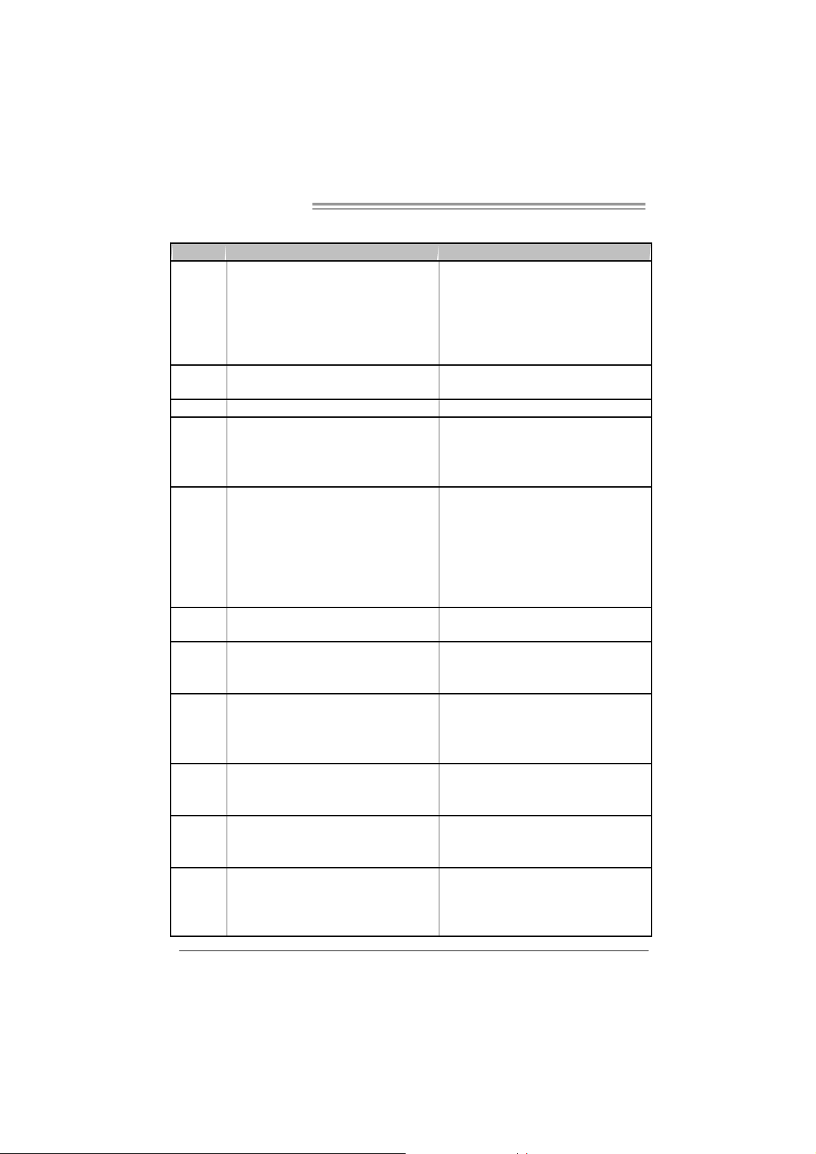
1.3 MOTHERBOARD FEATURES
NF50 0 AM 2G / NF50 0 AM 2L NF500U AM2 G
Socket AM2
AM D Athlon 64 / At hlon 64 FX / Althlon 64 X 2 /
CPU
FSB
Chi pset nVI DIA nFor c e 500 nVI DI A nForc e 500 Ultra
Super I/O
Main
Memory
IDE
SA TA
LAN
Sound
On Board
Connector
Sempron processors
AM D 64 Architecture enables 32 a nd 64 bit
computing
Supports Hyper Transport and Cool=n=Quiet
Support HyperTransport
Supports up t o 2GHz Bandwidth
ITE 8716F
Provides the most commonl
I/O functi onalit y.
Low Pin C ount Interface
DIMM Slots x 4
Eac h DIMM supports 256/512MB & 1GB DDR2
Max Memory Capicity 4GB
Dual Channel Mode DDR2 memory module
Supports DDR 2 533 / 667 / 800
Registered DIMM and ECC DIMM is not
supported
Integrated IDE Controller
Ultra DMA 33 / 66 / 100 / 133 Bus Master Mode
Integrated Serial ATA Controller
Data transfer rates up to 1.5 Gb/s.
SATA Version 1.0 specificat ion compliant.
Marvell 88E3016 PHY for NF500 AM2L
10 / 100 Mb/s Auto-Negotiation
Marvell 88E1116 PHY for NF500 AM2G
10 / 100 / 1000 M b/s Auto-Negotiation
C- media C M 6501
7. 1 c hannels audio out
USB Audio s upport
PCI s lot x4 PCI s lot x4
PCI Express x16 slot x1 PCI Express x16 sl ot x1 Slots
PCI Express x 1 slot x2 PCI Express x 1 slot x2
Fl oppy c onnector x1 Fl oppy c onnector x1
Printer Port connect or x1 Printer Port connect or x1
IDE C onnector x2 I DE Connector x2
SA TA Con nect or x4 SA TA Con nect or x4
us e d l egacy Supe
2
Socket AM2
AM D Athlon 64 / At hlon 64 FX / Althlon 64 X 2 /
Sempron processors
AM D 64 Architecture enables 32 a nd 64 bit
computing
Supports Hyper Transport and Cool=n=Quiet
Support HyperTransport
Supports up t o 2GHz Bandwidth
ITE 8716F
Provides the most commonly used legac y Super
I/O functi onalit y.
Low Pin C ount Interface
DIMM Slots x 4
Eac h DIMM supports 256/512MB & 1GB DDR2
Max Memory Capicity 4GB
Dual Channel Mode DDR2 memory module
Supports DDR 2 533 / 667 / 800
Registered DIMM and ECC DIMM is not
supported
Integrated IDE Controller
Ultra DMA 33 / 66 / 100 / 133 Bus Master Mode
Integrated Serial ATA Controller
Data transfer rates up to 3.0 Gb/s.
SATA Version 2.0 specificat ion compliant.
Marvell 88E1116 PHY
10 / 100 / 1000 M b/s Auto-Negotiation
C- media C M 6501
7. 1 c hannels audio out
USB Audio s upport
Page 5
NF500 AM2G / NF500 AM2L / NF500U AM2G
NF50 0 AM 2G / NF50 0 AM 2L NF500U AM2 G
Front Panel Connector x1 F ront Panel Connector x1
Front A udio Connector x1 Front Audio Connector x1
CD- in C onnec tor x1 CD-i n C onnector x1
S/PDIF out connector x1 S/PDIF out c onnector x1
CP U Fa n header x1 C PU F an header x1
Sys tem F an header x2 S ystem Fan hea der x2
CMOS clear header x1 CMOS clear header x1
USB connector x2 USB c onnector x2
Power Connector (24pin) x1 Power Connector (24pin) x1
Power Connector (4pin) x1 Power Connector (4pin) x1
PS/2 Keyboard x1
PS/2 Mouse x1
Back Panel
I/O
Board Size 218 x 293 (m m ) 218 x 293 (m m )
Special
Features
OS S upport
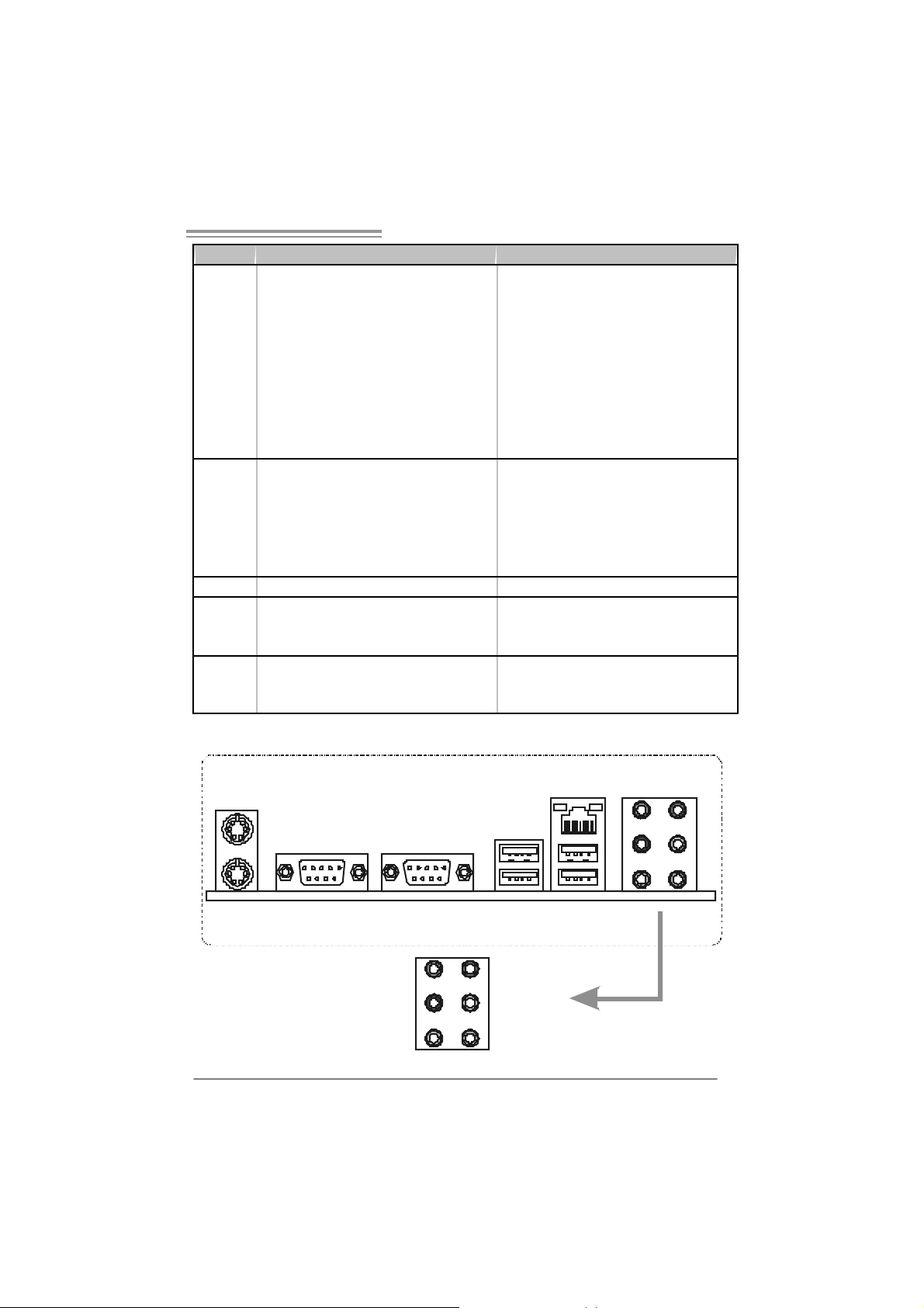
S e ri a l P ort x 1
LAN port x1
USB Port x4
Audio Jack x6
NVIDIA nTunes
NVIDIA firewall (for NF 500 AM 2G only)
RAID 0 / 1 / 0+ 1 support
Windows 2K / XP / VISTA
Biostar Reserves the right to add or remove
support for any OS With or without notice.
PS/2 Keyboard x1
PS/2 Mouse x1
S e ri a l P ort x 1
LAN port x1
USB Port x4
Audio Jack x6
NVIDIA nTunes
NVIDIA firewall
RAID 0 / 1 / 0+ 1 / 5 support
Windows 2K / XP / VISTA
Biostar Reserves the right to add or remove
support for any OS With or without notice.
1.4 REAR PANEL CONNECTORS
PS/2
Mouse
P S /2
Keyboard
COM1 COM2
(optional)
Center
Rear
Side
Line In
Line Out
Mic In
LAN
USBX2USBX2
3
Page 6
Motherboard Manual
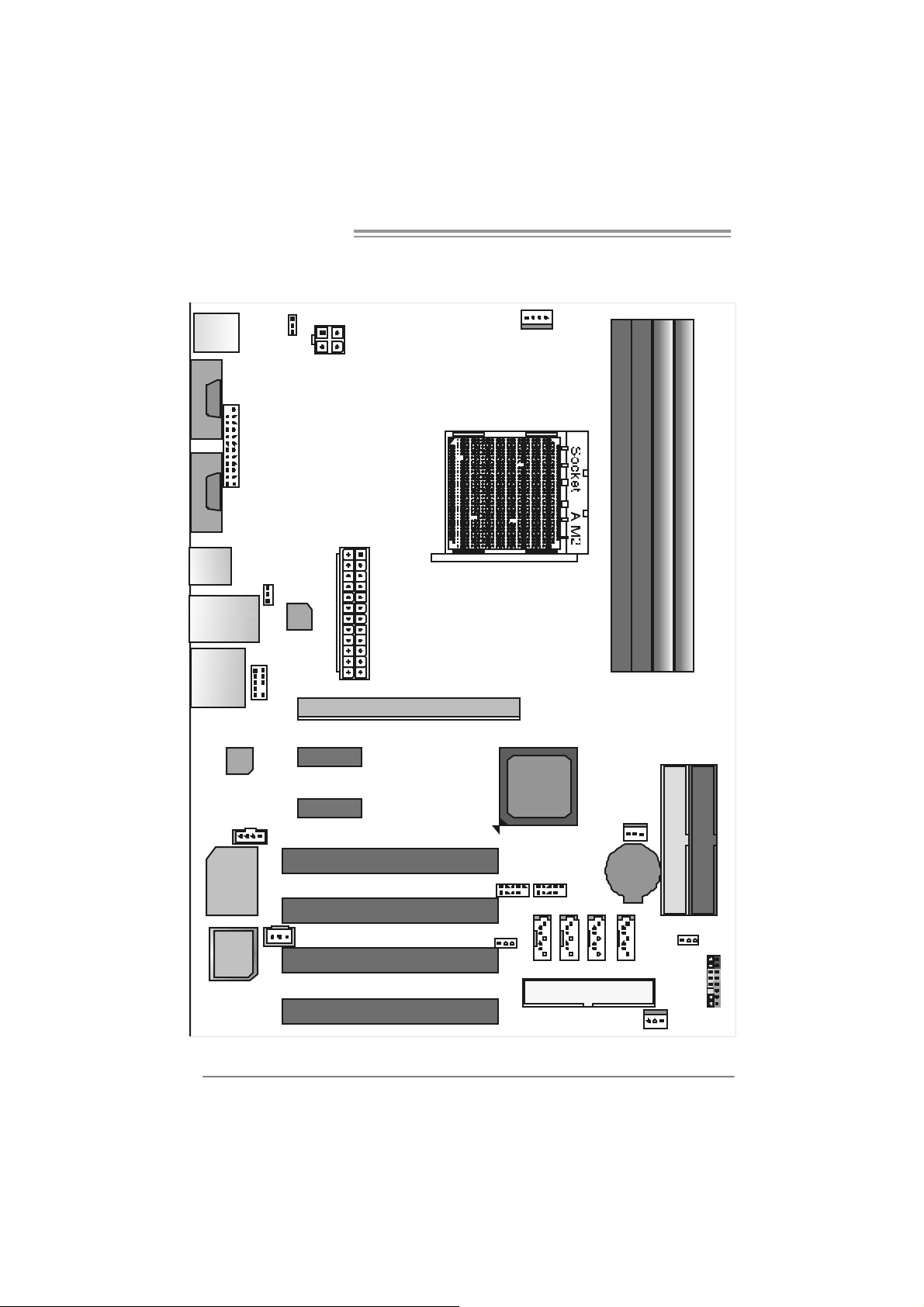
1.5 MOTHERBOARD LAYOUT FOR NF500 AM2L / NF500
AM2G
JCFAN1
JKBMS1
JCOM1
(optional)
JCOM2
JPRNT 1
JKBMSV1
JATXPWR2
JATXPWR1
DIM MA1
DIM MB1
DIM MA2
DIM MB2
JUSB1
JUSBLAN1
JAUDI O2
4
J AUDIO F 1
Codec
JC DIN1
Super I / O
BIOS
Note: represents the 1■
J USBV1
LAN
PEX1_1
PEX1_2
JSPDIF_ OUT1
PCI1
PCI2
PCI3
PCI4
PEX16
st
pin.
nVID IA
nForce500
JUSB2 JUSB3
JUSBV2
JN FAN1
IDE2
IDE1
BAT1
JSATA2JSATA1
FDD1
J SATA4JSATA3
JCMOS1
JPANEL1
JSF AN1
Page 7
NF500 AM2G / NF500 AM2L / NF500U AM2G
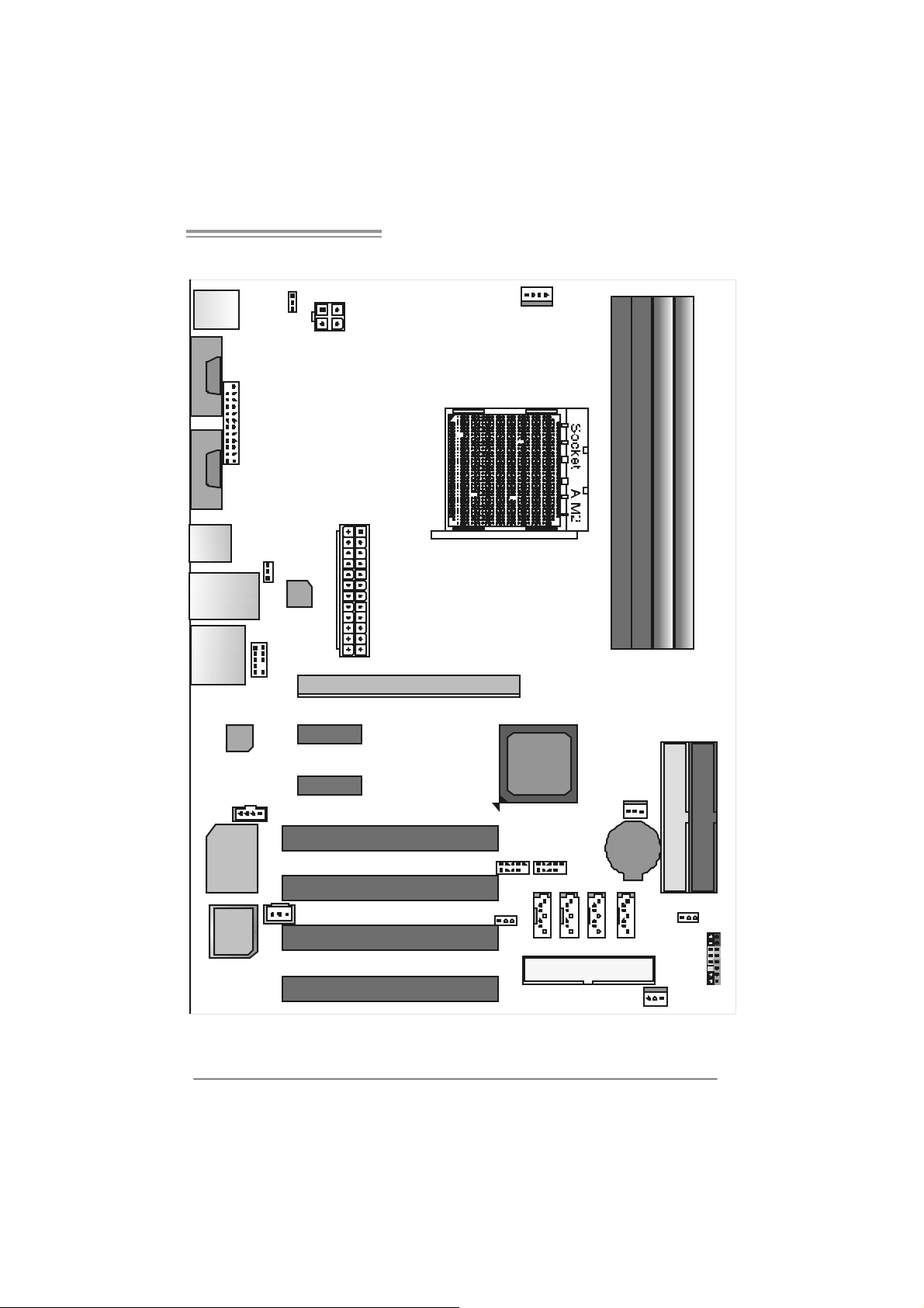
1.6 MOTHERBOARD LAYOUT FOR NF500U AM2G
JCFAN1
JKBMS1
JCOM1
(optional)
JCOM2
JKBMSV1
JATXPWR2
JPRNT 1
JATXPWR1
DIM MA1
DIM MB1
DIM MB2
DIM MA2
JUSB1
J USBV1
JUSBLAN1
JAUDI O2
J AUDIO F 1
Codec
JC DIN1
Super I / O
BIOS
Note: represents the 1■
LAN
PEX1_1
PEX1_2
JSPDIF_ OUT1
PCI1
PCI2
PCI3
PCI4
PEX16
st
pin.
nVID IA
nForce500
Ultra
JUSB2 JUSB3
JUSBV2
JN FAN1
IDE2
IDE1
BAT1
JSATA2JSATA1
FDD1
J SATA4JSATA3
JCMOS1
JPANEL1
JSF AN1
5
Page 8
Motherboard Manual
CHAPTER 2: HARDWARE INSTALLATION
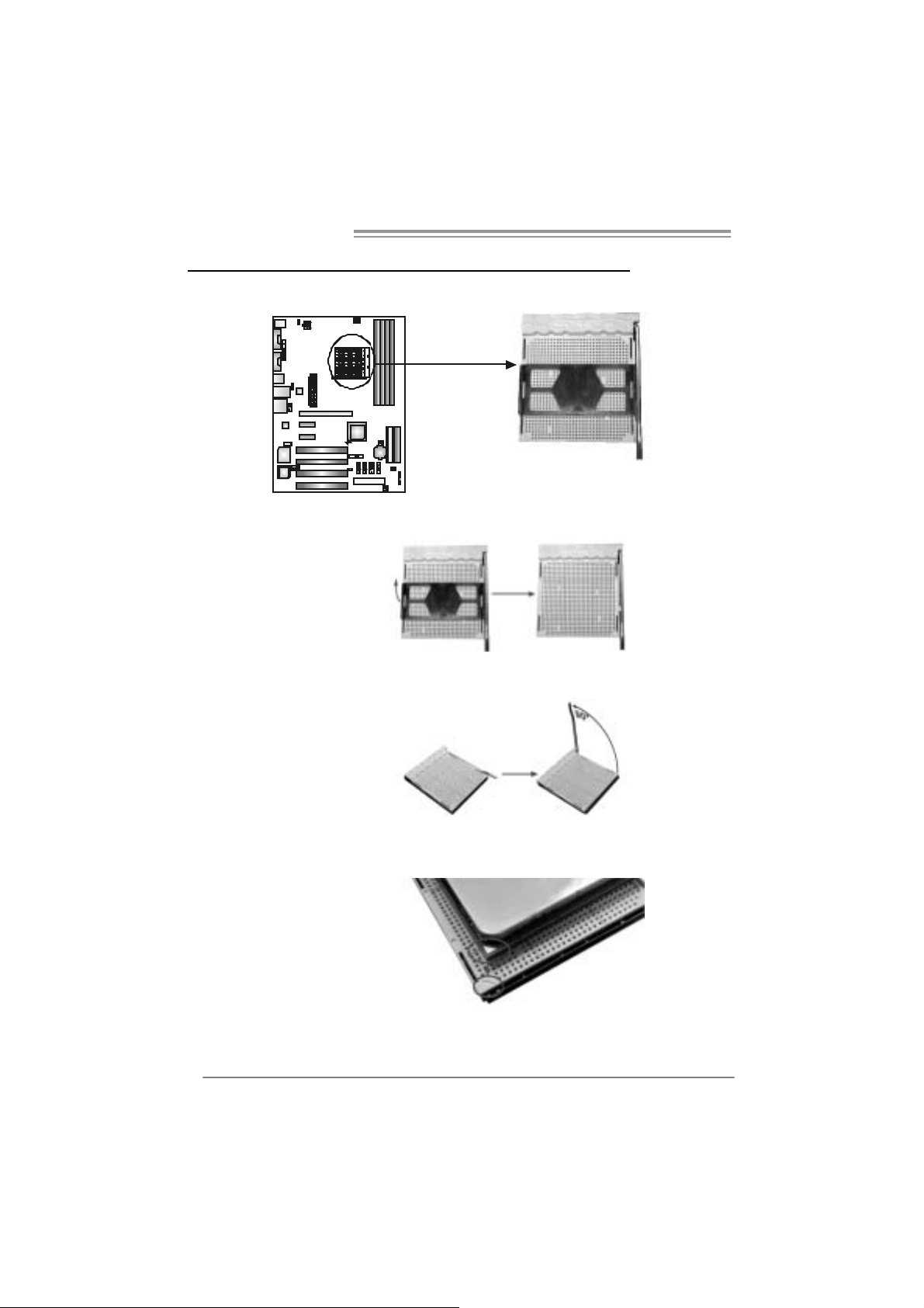
2.1 INSTALLING CEN TRAL PROCESSING UNIT (CPU)
Step 1: Remove the socket protection cap.
Step 2: Pull the lever toward direction A from the socket and then raise the
lever up to a 90-degree angle.
Step 3: Look for the white triangle on socket, and the gold triangle on
CPU should point towards this white triangle. The CPU will fit only
in the correct orientation.
6
Page 9

NF500 AM2G / NF500 AM2L / NF500U AM2G
Step 4: Hold the CPU down firmly, and then close the lever toward direct
B to complete the installation.
Step 5: Put the CPU Fan on the CPU and buckle it. Connect the CPU
FAN power cable to the JCFAN1. This completes the installation.
7
Page 10
Motherboard Manual
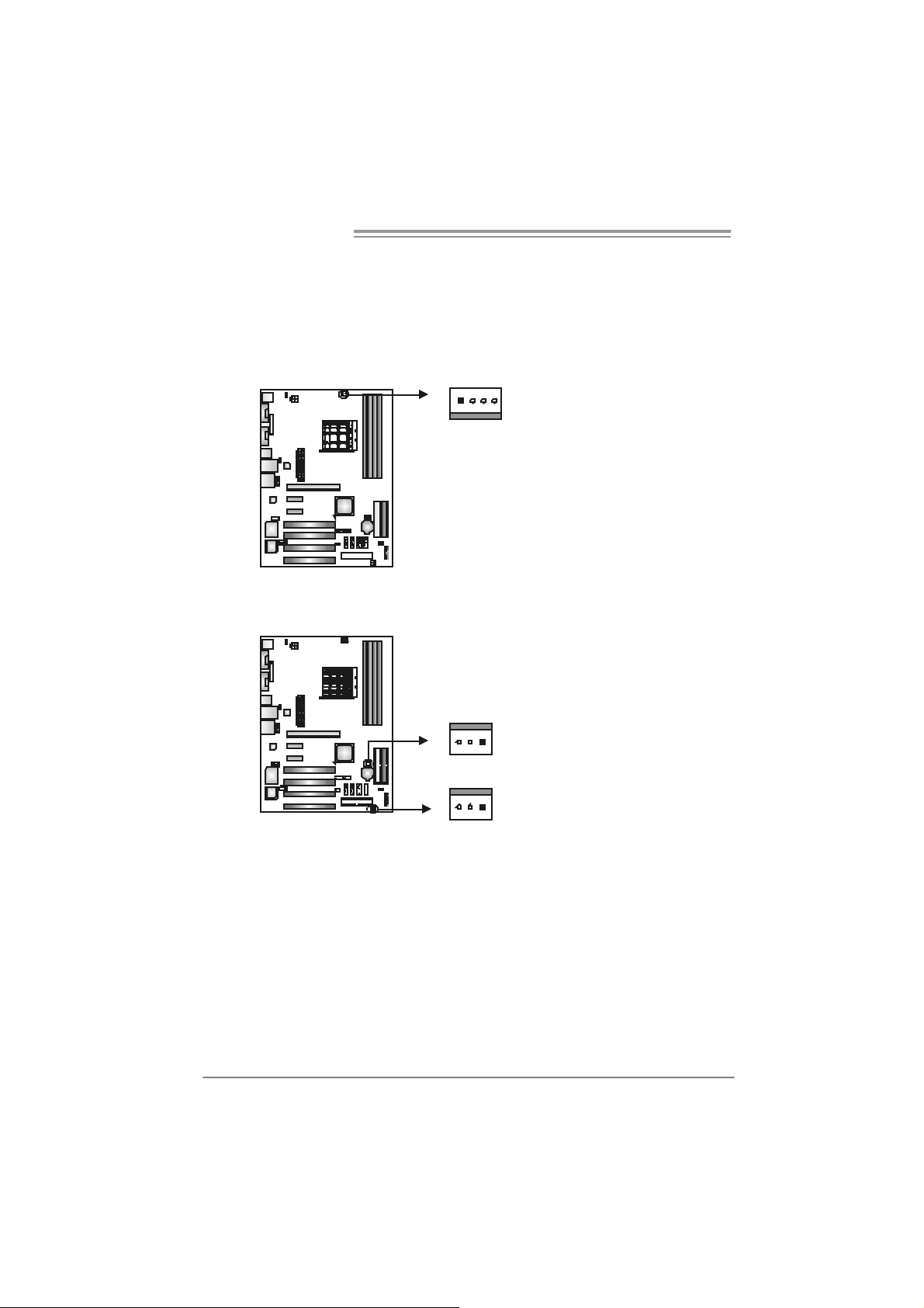
2.2 FAN HEADERS
These fan headers support cooling-fans built in the computer. The fan
cable and connector may be different according to the fan manufacturer.
Connect the fan cable to the connector while matching the black wire to
pin#1.
JCFAN1: CPU Fan Header
JCFAN1
14
JSFAN1 : System Fan Head er
JNFAN1: North Bri dge Fan Heade r
1133
JNFAN1
Pin
1 Ground
2 +12V
3
4 Smart Fan
Pin
1 Ground
2 +12V
3 FAN RPM rate
Assignment
FAN RPM rate
sense
Control (By Fan)
Assignment
sense
JSFAN1
Note:
The J SFAN 1 an d JNF AN 1 s upport 3-pin hea d c onn ect or . When c onnec ti ng with wires
ont o co nnec tors, pl eas e note th at t he r e d wire is th e pos iti ve a nd s hould be c onn ec t ed to
pin#2, a nd th e bl ac k wire is Gr ound and s hould b e c onnect ed to GN D .
8
Page 11
NF500 AM2G / NF500 AM2L / NF500U AM2G
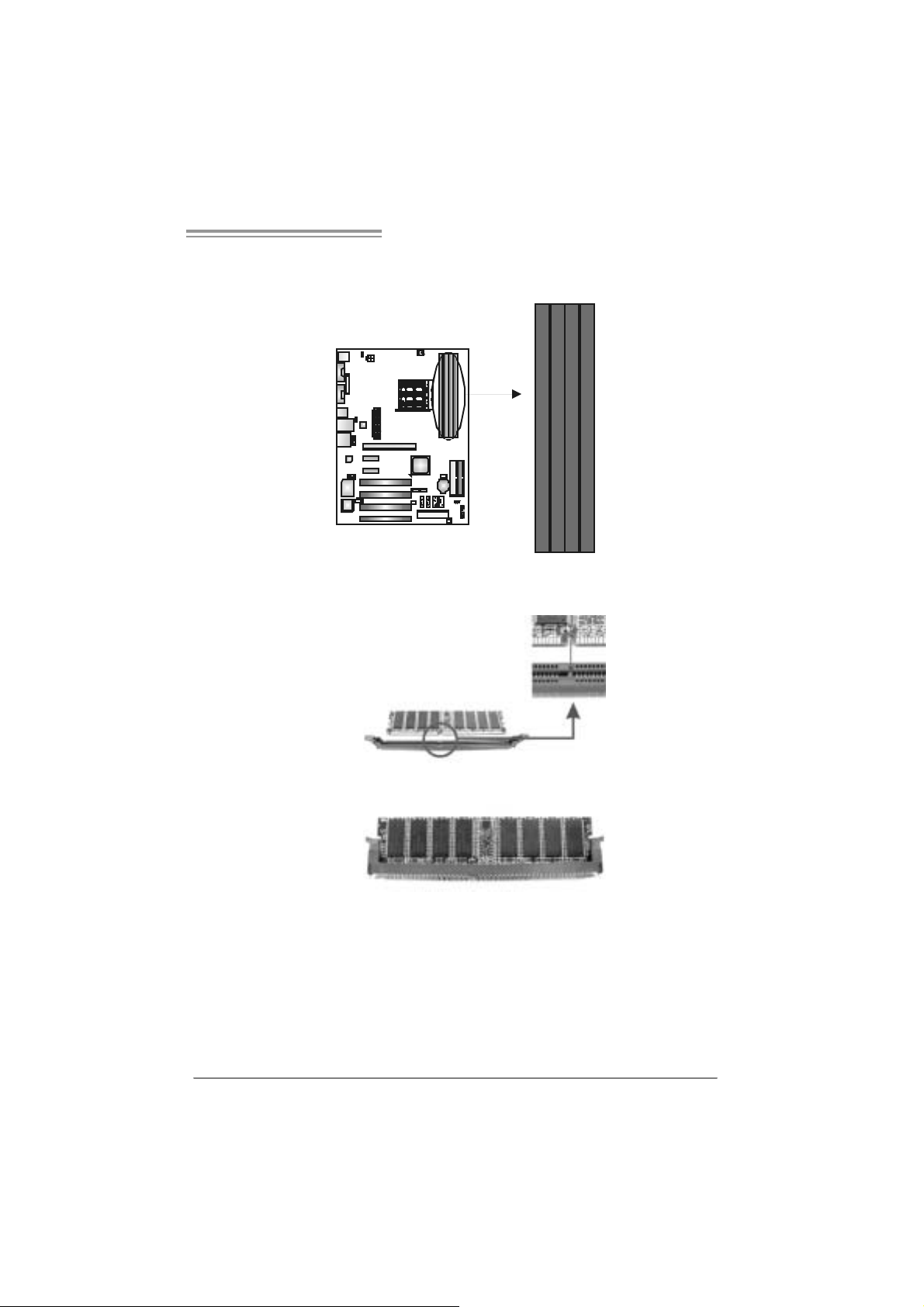
2.3 INSTALLING SYSTEM MEMORY
A. Memory Modu le s
DIMMA1
DIMMB1
DIMMA2
DIMMB2
1. Unlock a DIMM slot by pressing the retaining clips outward. Align a
DIMM on the slot such that the notch on the DIMM matches the
break on the Slot.
2. Insert the DIMM vertically and firmly into the slot until the retaining
chip snap back in place and the DIMM is properly seated.
9
Page 12
Motherboard Manual
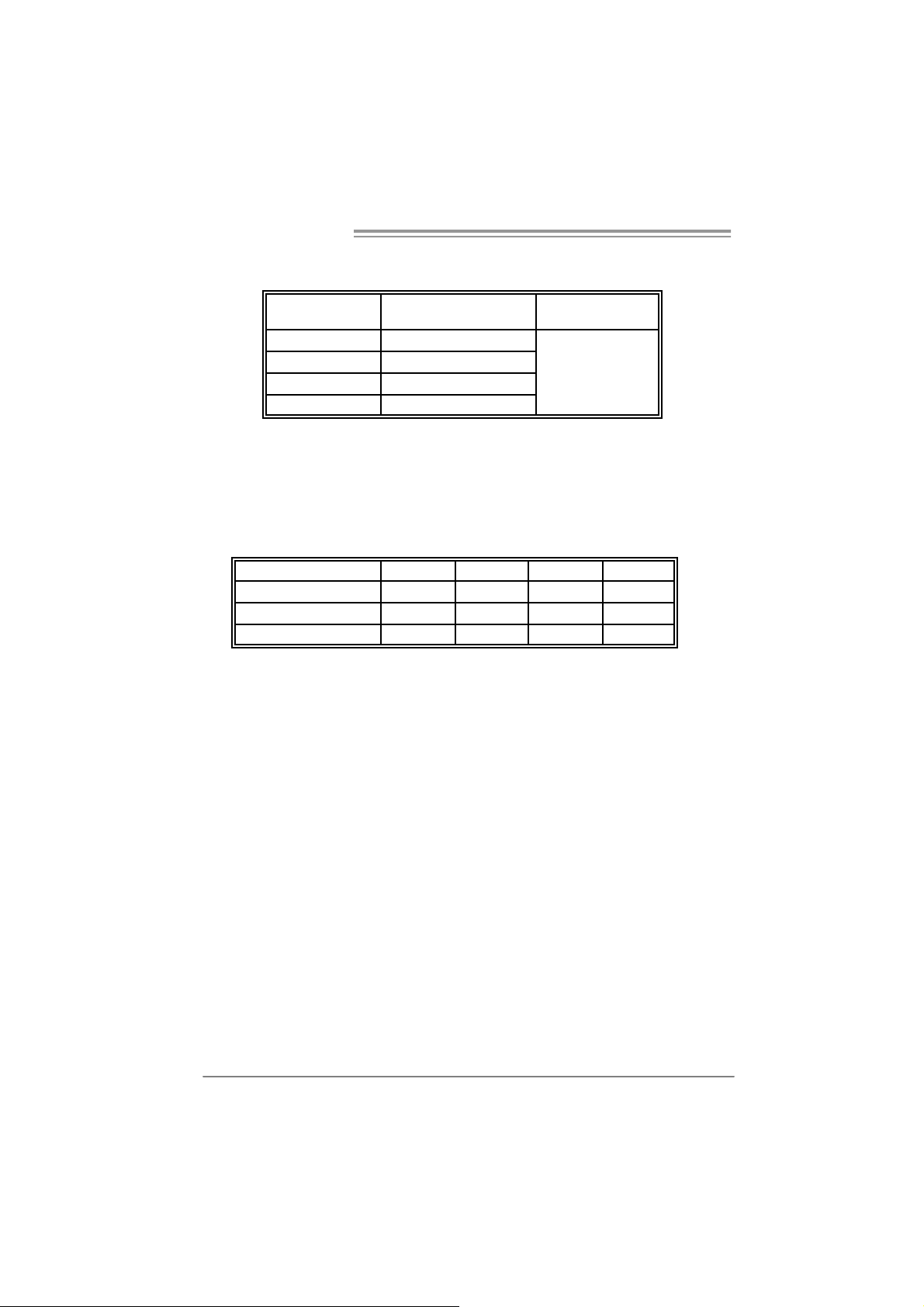
B. Memory Capacity
DI MM Socket
Location
DIMMA1 256MB/512MB/1024MB
DIMMB1 256MB/512MB/1024MB
DIMMA2 256MB/512MB/1024MB
DIMMB2 256MB/512MB/1024MB
DDR Module
To t al Memo r y
Size
Max is 4 GB.
C. Dual Channel Memory installatio n
To trigger the Dual Channel f unction of the motherboard, the memory module
must meet the following requirements:
Install memory module of the same density in pairs, shown in t he f ollowing
table.
Du al Channel Statu s
Enabled O O X X
Enabled X X O O
Enabled O O O O
(O means memory installed, X means memory not installed.)
The DRAM bus width of the memory module must be the same (x8 or
x16)
DIMMA1
DIMMB1 DIMMA2 DIMMB2
10
Page 13
NF500 AM2G / NF500 AM2L / NF500U AM2G
2.4 CONNECTORS AND SLOTS
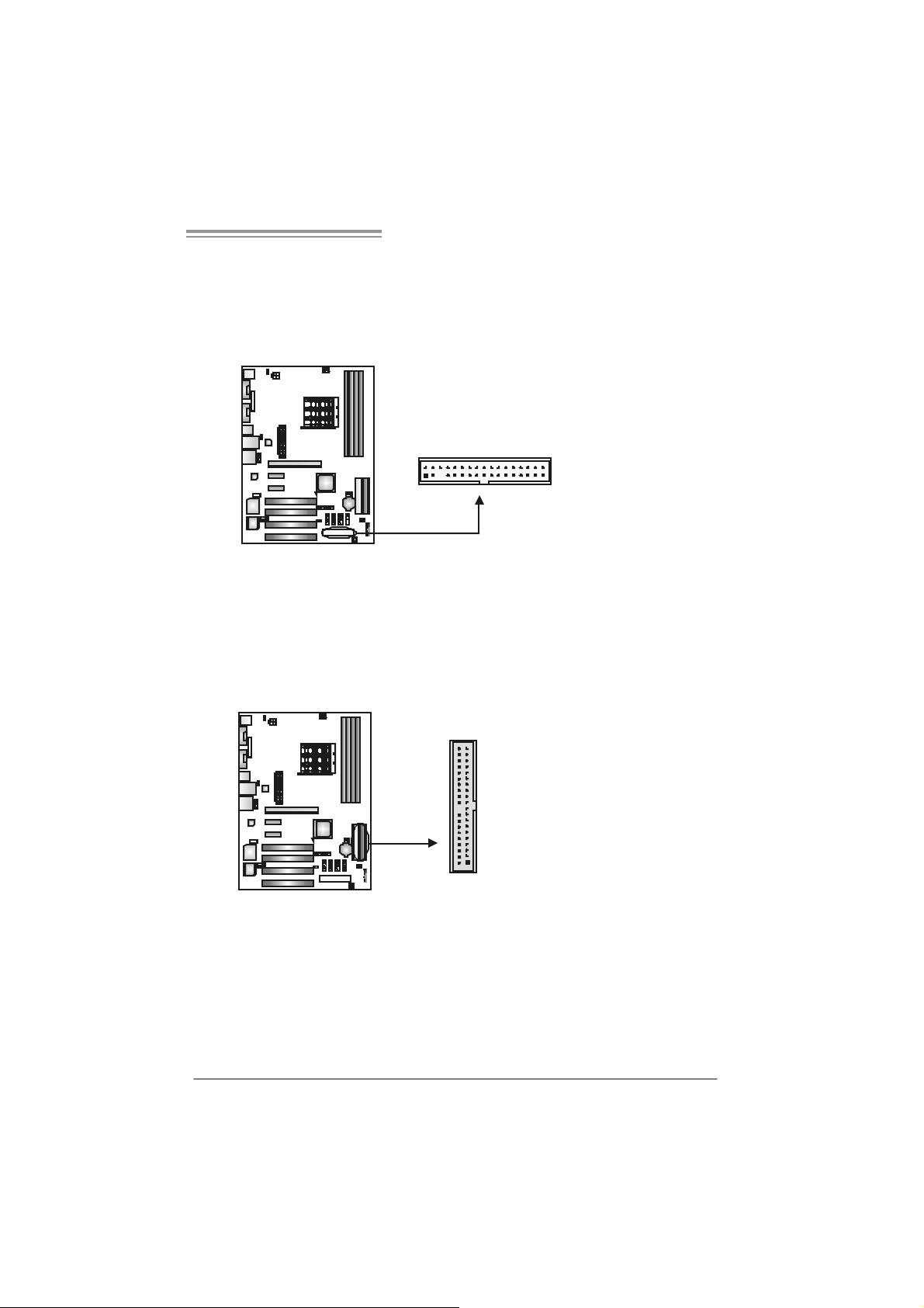
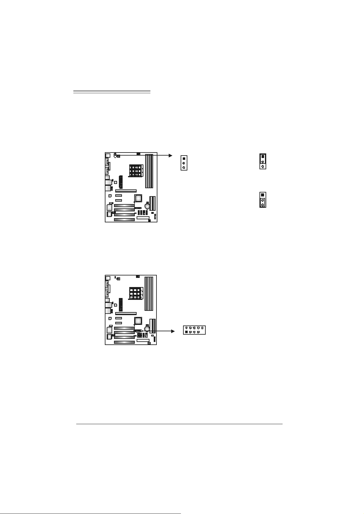
FDD1: Flo ppy Disk Connec tor
The motherboard prov ides a standard floppy disk connector that supports 360K,
720K, 1.2M, 1.44M and 2.88M f loppy disk ty pes. This connector supports the
prov ided f loppy drive ribbon cables.
IDE1/IDE2 : Har d Di sk Connectors
The motherboard has a 32-bit Enhanced PCI IDE Controller that prov ides PIO
Mode 0~4, Bus Master, and Ultra DMA 33/66/100/133 f unctionality. It has two
HDD connectors IDE1 (primary) and IDE2 (secondary).
The IDE connectors can connect a master and a slav e driv e, so you can
connect up to four hard disk drives. The f irst hard drive should always be
connected to IDE1.
2
1
21
3
4
33
3940
IDE2IDE 1
11
Page 14
Motherboard Manual
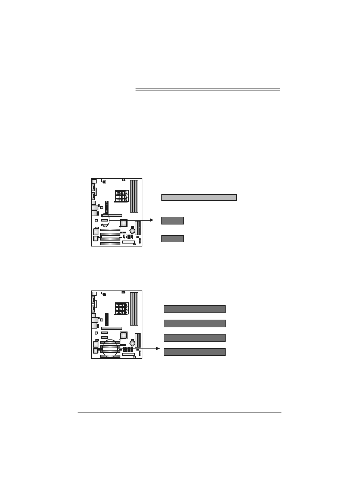
PEX16: PCI-Express x16 Slot
- PCI-Ex press 1.0a compliant.
- Maximum theoretical realized bandwidth of 4GB/s simultaneously per
direction, for an aggregate of 8GB/s totally.
PEX1_1/PEX1_2: PCI-Express x1 slots
- PCI-Ex press 1.0a compliant.
- Data transfer bandwidth up to 250MB/s per direction; 500MB/s in total.
- PCI-Ex press supports a raw bit-rate of 2.5Gb/s on the data pins.
- 2X bandwidth ov er the traditional PCI architecture.
PEX16
PEX1_1
PEX1_2
PCI1~PCI4: Peripheral Component Interconnect Slo ts
This motherboard is equipped with 4 standard PCI slots. PCI stands f or
Peripheral Component Interconnect, and it is a bus standard for expansion
cards. This PCI slot is designated as 32 bits.
12
PCI1
PCI2
PCI3
PCI4
Page 15
NF500 AM2G / NF500 AM2L / NF500U AM2G
_
CHAPTER 3: HEADERS & JUMPERS SETUP
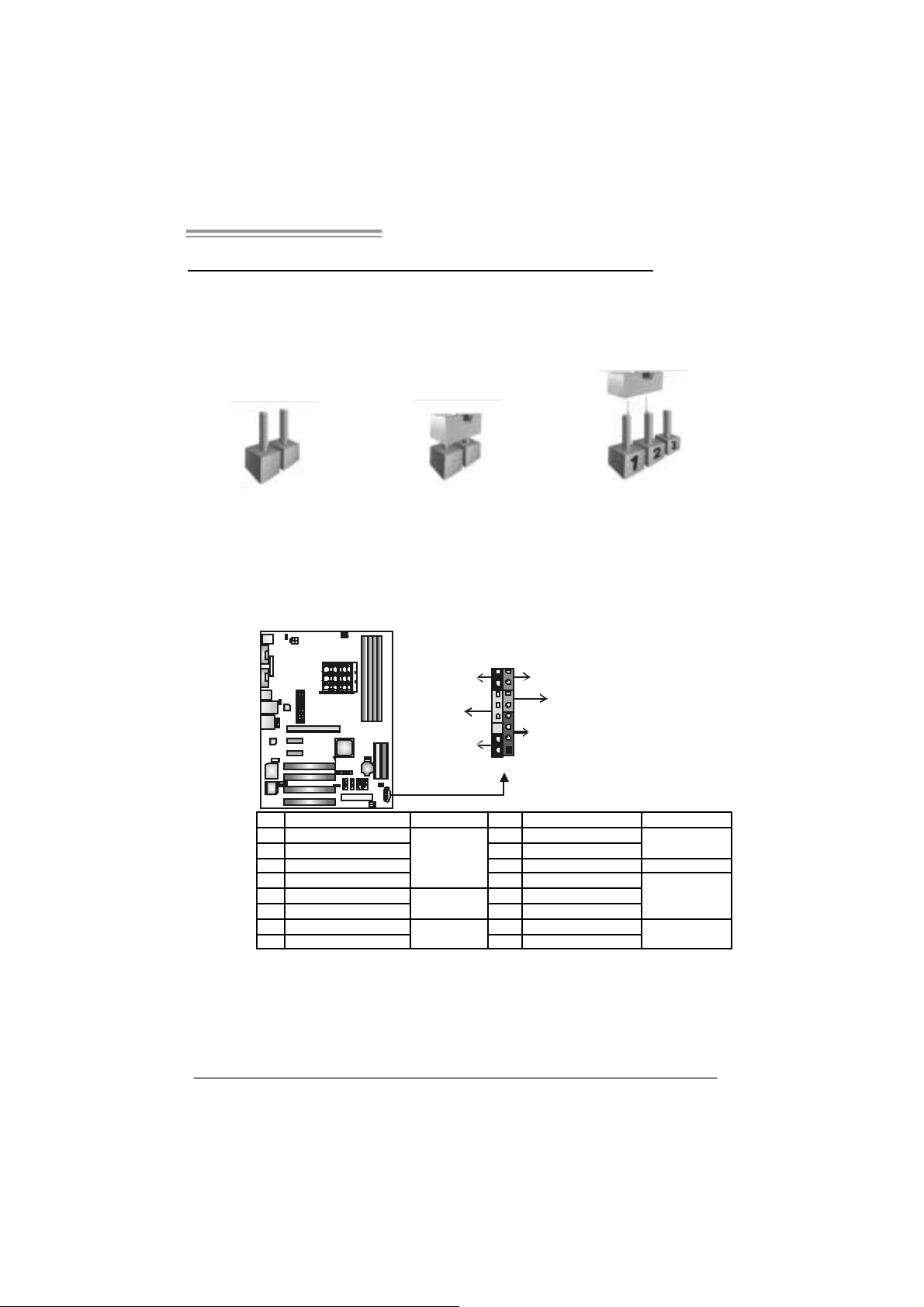
3.1 HOW TO SET UP JUMPERS
The illustration shows how to set up jumpers. When the jumper cap is
placed on pins, the jumper is “close”, if not, that means the jumper is
“open”.
Pin opened Pin closed Pin1-2 closed
3.2 DETAIL SETT INGS
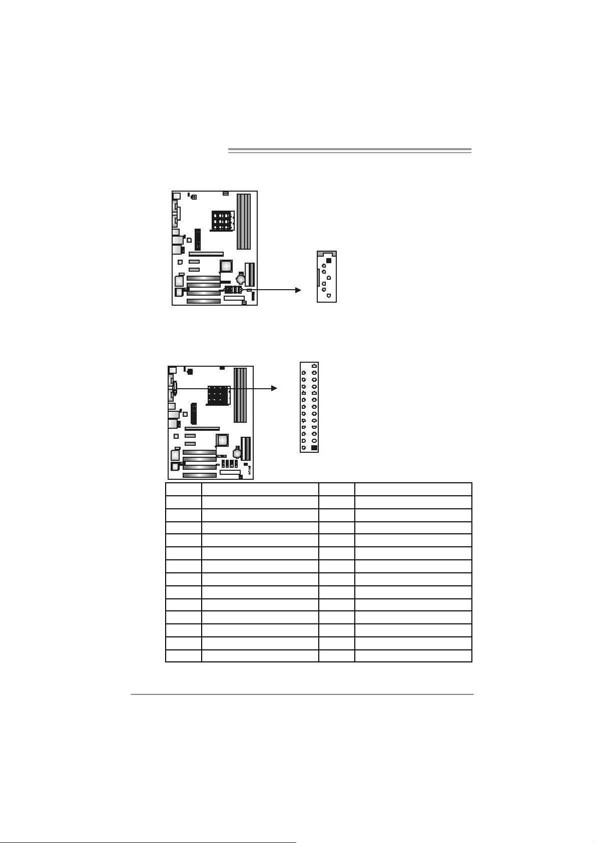
JPANEL1: Front Panel Header
This 16-pin connector includes Power-on, Reset, HDD LED, Power LED, Sleep
button and speaker connection. It allows user to connect the PC case’s f ront
panel switch functions.
16
8
-
++
9
RST
HLED
+
SP K
1
PWR
On/Off
LED
SLP
Pin Assignment Functio n Pin Assignment Function
1 +5V 9 Sleep control
2 N/A 10 Ground
3 N/A 11 N/A N/A
4 Speaker
5 HDD LED (+) 13 Power LED (+)
6 HDD LED (-)
7 Ground 15 Power button
8 Reset control
Speaker
Connector
Hard drive
LED
Reset button
12 P ower LE D (+ )
14 P ower LE D (-)
16 Ground
Sleep button
Power LED
Power-on button
13
Page 16
Motherboard Manual
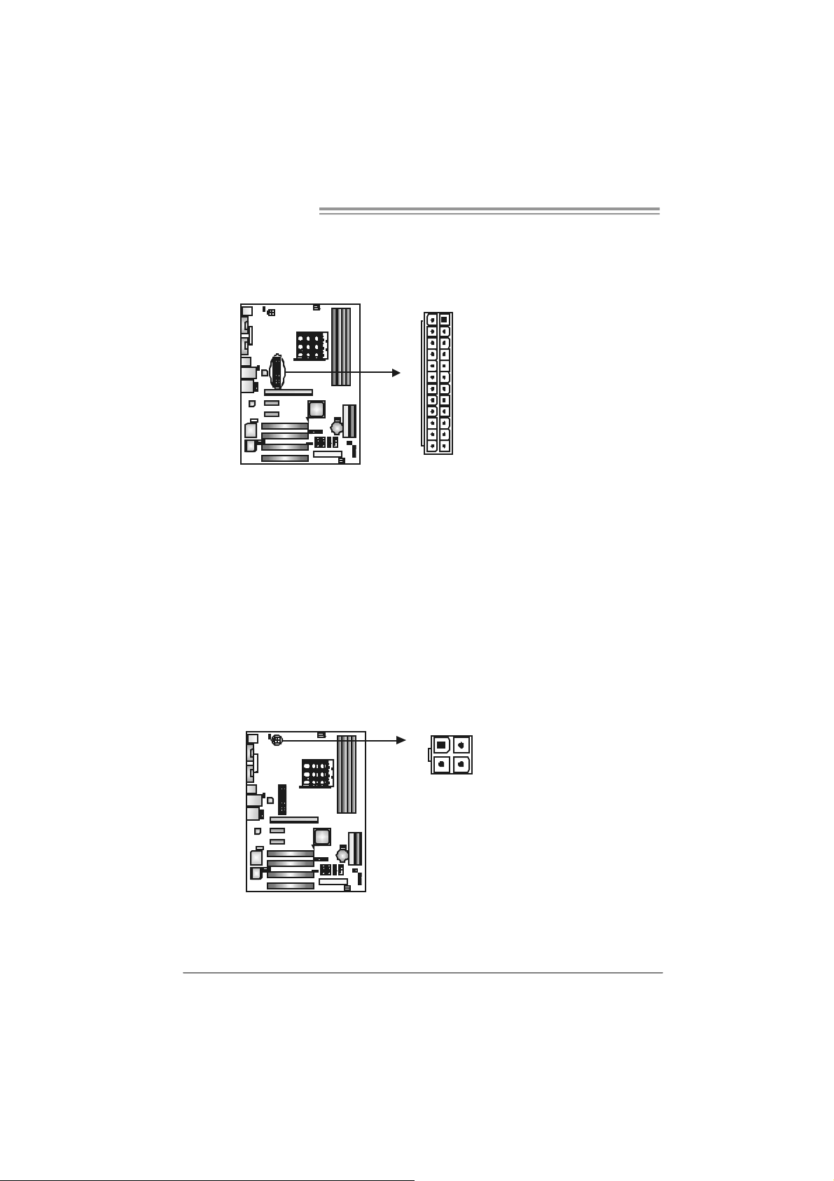
JATXPWR1: ATX Powe r So u rce Conne ctor
This connector allows user to connect 24-pin power c onnector on the ATX
power supply.
Pin Assignment Pin Assignment
13 +3.3V 1 + 3.3V
14 -12V 2 +3.3V
15 Gr oun d 3 Gr oun d
16 PS_ON 4 +5V
17 Gr oun d 5 Gr oun d
18 Gr oun d 6 +5V
19 Gr oun d 7 Gr oun d
20 NC 8 PW_ OK
21 +5V 9 Stand b y Volt age+5V
22 +5V 10 +12V
23 +5V 11 +12V
24 Gr oun d 12 +3.3V
113
1224
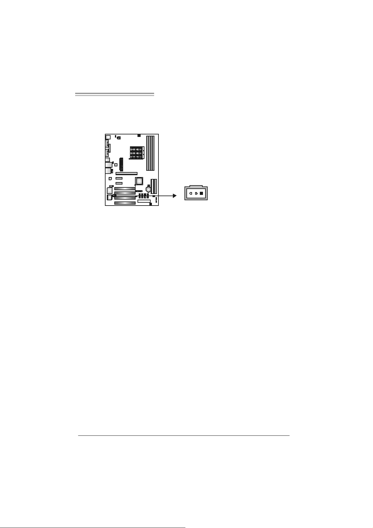
JATXPWR2: ATX Powe r So u rce Conne ctor
By connecting this connector, it will provide +12V to CPU power circuit.
14
1
4
32
Pin
Assignment
1 +12V
2 +12V
3 Ground
4 Ground
Page 17
NF500 AM2G / NF500 AM2L / NF500U AM2G
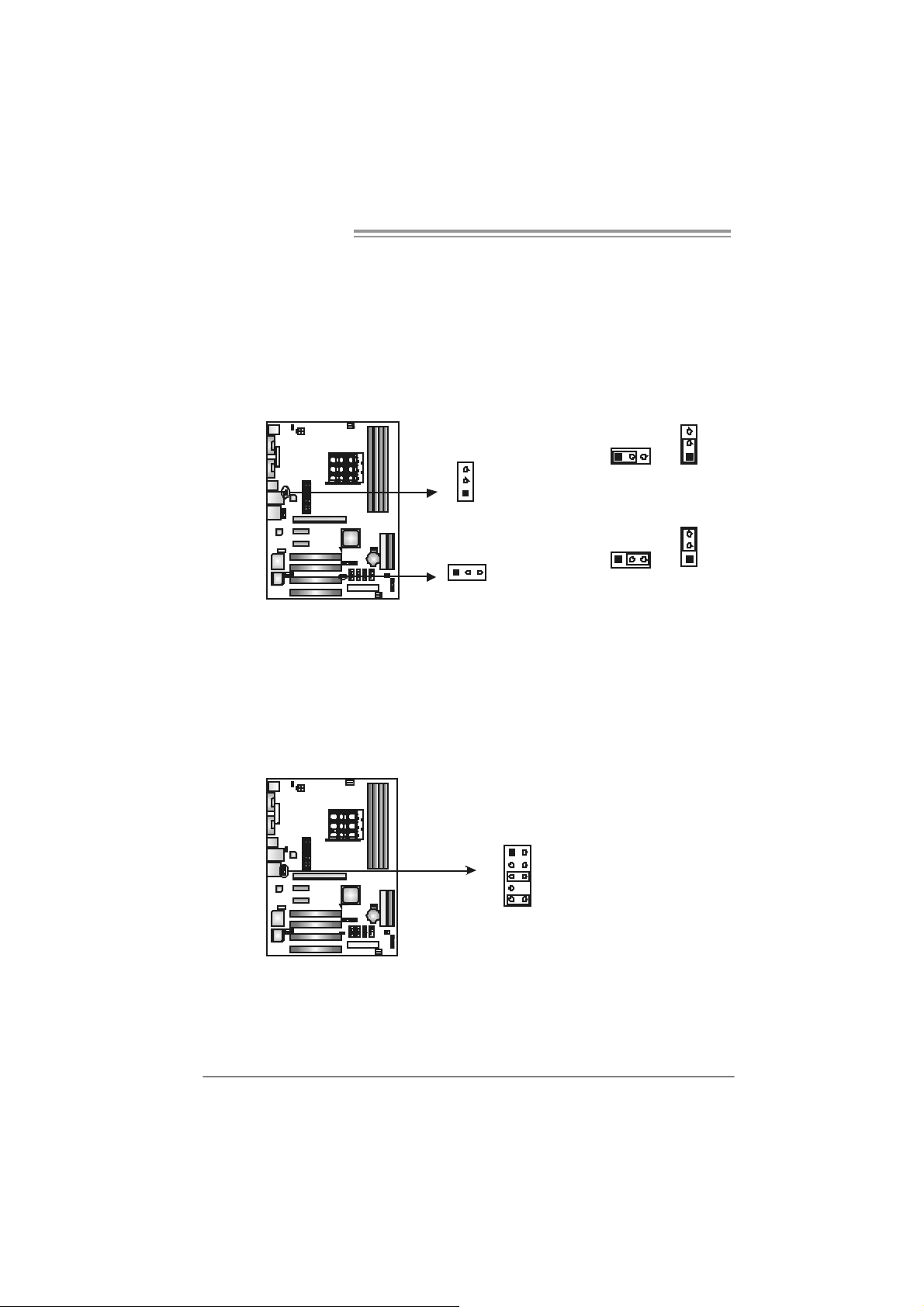
JKBMSV1: Power Source Selection Heade rs for Keyboard/Mouse
Pin 1-2 C lose:
JKBMSV1: +5V for PS/2 key board and mouse。
Pin 2-3 C lose:
JKBMSV1: PS/2 keyboard and mouse are powered with +5V standby
v oltage.
1
3
1
3
Pin 1-2 close
1
3
Pin 2-3 close
JUSB2/JUSB3: Heade rs for USB 2.0 Ports at Front Panel
This header allows user to connect additional USB cable on the PC f ront panel,
and also can be connected with internal USB devices, like USB card reader.
USB2 / USB3
Pin Assignment
1 +5V (fused)
2 +5V (fused)
3 USB-
4 USB5 USB+
JUSB2 JU SB3
2
1
10
9
6 USB+
7 Ground
8 Ground
9 Key
10 NC
15
Page 18
Motherboard Manual
JU SB V1/JUSB V2: Powe r Source H eaders for USB P orts
Pin 1-2 C lose:
JUSBV1: +5V for USB ports at JUSBLAN1.
JUSBV2: +5V for USB ports at f ront panel (JUSB2/JUSB3).
Pin 2-3 C lose:
JUSBV1: USB ports at JUSBLAN1 are powered by +5V standby voltage.
JUSBV2: USB ports at front panel (JUSB2/JUSB3) are powered by +5V
standby v oltage.
3
JUSBV1
Pin 1-2 close
3
31
1
3
3
1
113
JUSBV2
1
Pin 2-3 close
Note:
In ord er to s up por t this f unctio n “P ower- On s yst em vi a U SB de vic e,” “ JU SBV1 / JUSB V2”
jumper ca p should be pl ac ed on Pi n 2-3 in di vidu al l y.
JAUDIOF1: Fron t Panel Au dio Heade r
This header allows user to connect t he front audio output cable with the PC f ront
panel. It will disable the output on back panel audio c onnectors.
Pin Assignment
1 Mic Left in
2 Ground
1
9210
3 Mic Right in
4 GPIO
5 Right line in
6 Jack Sense
7 Front Sense
8 Key
9 Left line in
10 Jack Sense
16
Page 19
NF500 AM2G / NF500 AM2L / NF500U AM2G
JCDIN1: CD-ROM Aud io-in Connector
This connector allows user to connect the audio source f rom the v ariaty dev ices,
like CD-ROM, DVD-ROM, PCI sound card, PCI TV turner card etc..
Assignment
Pin
1 Left Channel Input
2 Ground
14
JCMOS 1 : C lear CMO S He ader
By placing the jumper on pin2-3, it allows user to restore the BIOS saf e setting
and the CMOS data, please carefully f ollow the procedures to avoid damaging
the motherboard.
3 Ground
4 Right Channel Input
13
Pin 1-2 Close:
Normal Operation (default).
13
13
Pin 2-3 Close:
Clear CMOS data.
※ Clear CMOS Procedures:
1. Remov e AC power line.
2. Set the jumper to “Pin 2-3 close”.
3. Wait f or f ive seconds.
4. Set the jumper to “Pin 1-2 close”.
5. Power on the AC.
6. Reset y our desired pas sword or c lear the CMOS data.
17
Page 20
Motherboard Manual
JSATA1~JS ATA4: Serial ATA Connecto rs
The motherboard has a PCI to SATA Controller with 4 channels SATA interf ace.
JS ATA1 J S ATA2 J SATA3 JS ATA 4
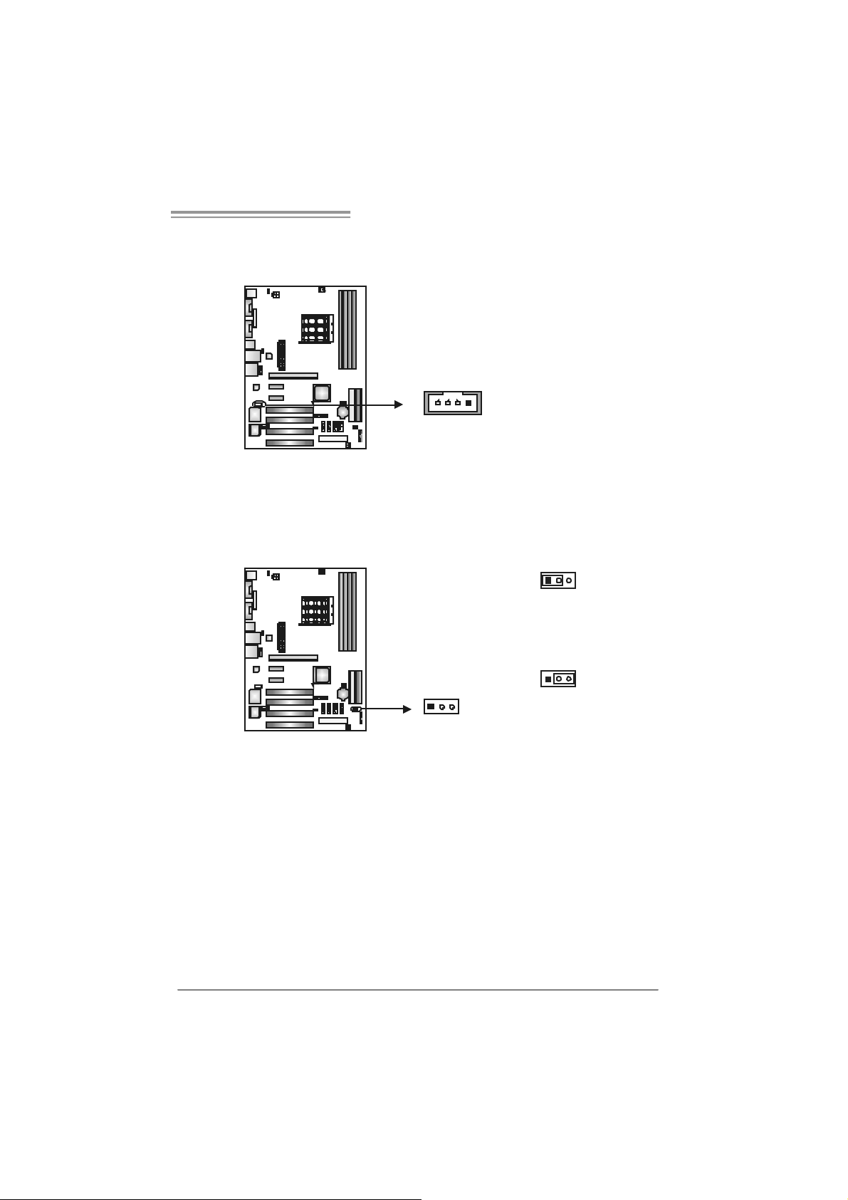
JPRNT1: Printer Port Connector
This header allows you to connector printer on the PC.
25
Pin
Assignment
1 Ground
2 TX +
3 TX -
1
4
7
4 Ground
5 RX6 RX+
7 Ground
18
12
Pin Assignment Pin Assignment
1 -Strobe 14 Ground
2 -ALF 15 Data 6
3 Data 0 16 Ground
4 -Error 17 Data 7
5 Data 1 18 Ground
6 -Init 19 -ACK
7 Data 2 20 Ground
8 -Scltin 21 Busy
9 Data 3 22 Ground
10 Ground 23 PE
11 Data 4 24 Ground
12 Ground 25 SCLT
13 Data 5 26 Key
Page 21
NF500 AM2G / NF500 AM2L / NF500U AM2G
JSPDI F_O UT1: Di gital Audio-out Conne ctor
This connector allows user to connect the PCI bracket SPDIF output header.
Pin
Assignment
1 +5V
2 SPDIF_OUT
3 Ground
13
19
Page 22
Motherboard Manual
CHAPTER 4: NVIDIA RAID FUNCTIONS
4.1 OPERATION SYSTEM
z Supports Windows XP Home/Prof essional Edition, and Windows 2000 Prof essional.
4.2 RAID ARRAYS
NVRAID supports the following ty pes of RAID arrays:
RAID 0: RAID 0 defines a disk striping scheme that improves disk read and write times for
many applications.
RAID 1: RAID 1 defines t echniques for mirrori ng data.
RAID 0+1: RAID 0+1 combines the techniques used in RAID 0 and RAID 1.
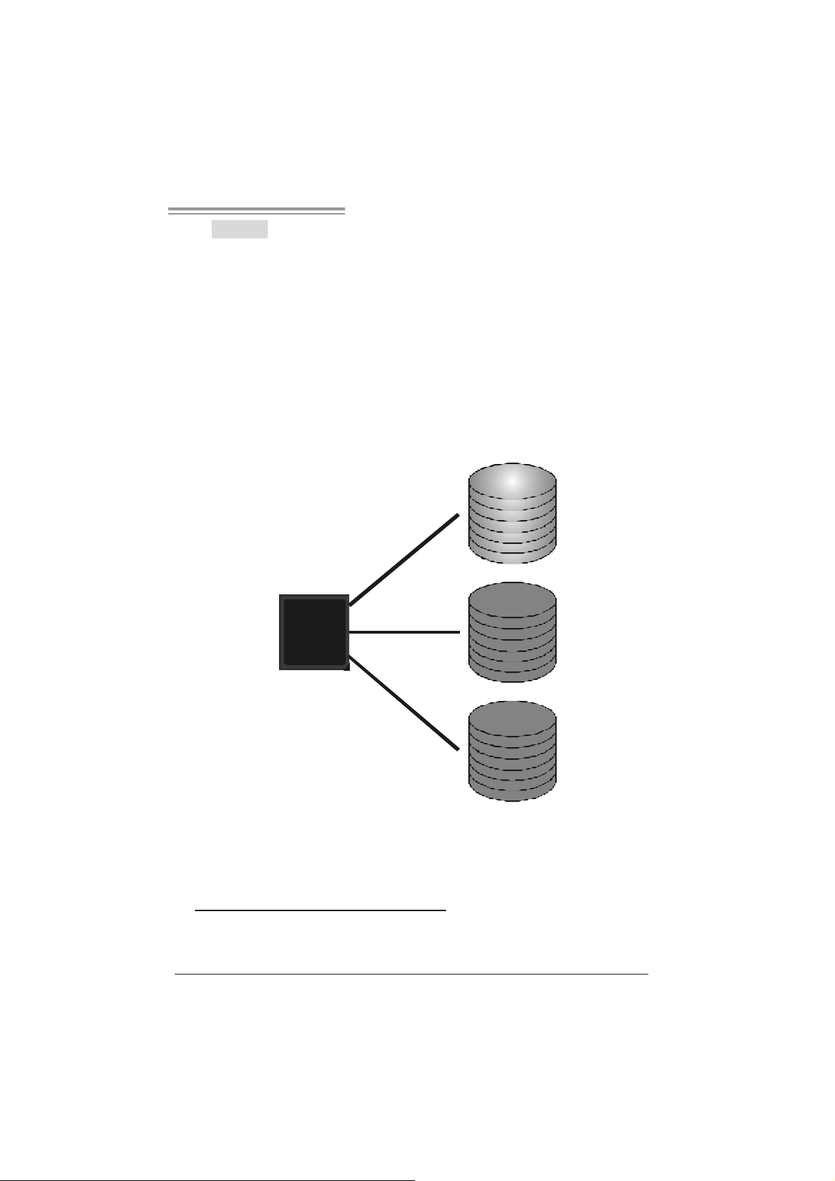
4.3 HOW RAID WORKS
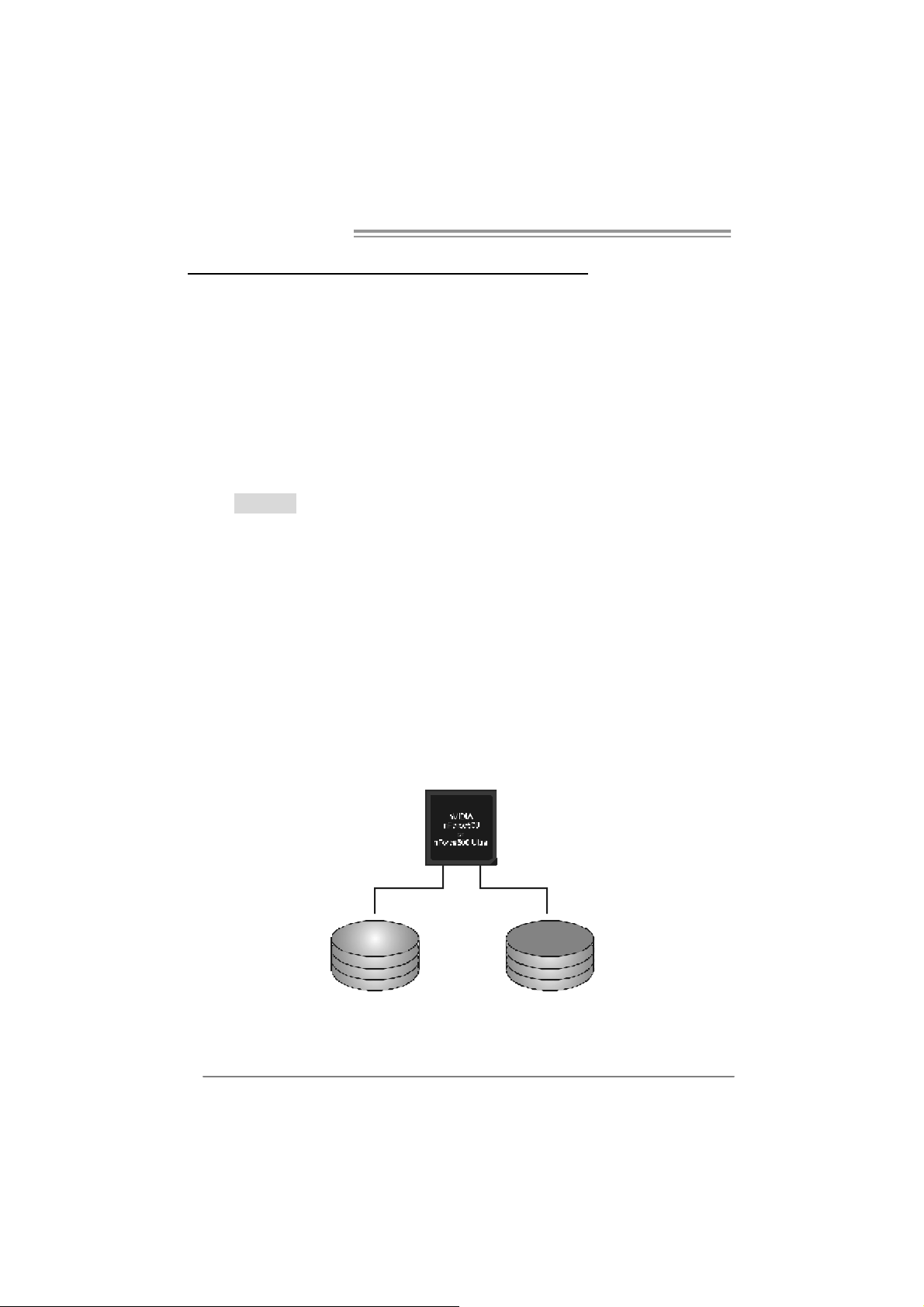
RAID 0:
The controller “stripes” data across multiple drives in a RAID 0 array system. It breaks
up a large file into smaller blocks and performs disk reads and writes across multiple
drives in parallel. The size of each block is determined by the stripe size parameter,
which you set during the creation of the RAID set based on the system environment. This
technique reduces overall disk access t ime and offers high bandwidth.
Fea tures and Be nefits
Drives: Minimum 1, and maximum is up to 6 or 8. Depending on the
platform.
Uses: Intended for non-critical data requiring high data throughput, or any
env ironment that does not require fault tolerance.
Benefits: prov ides increased data throughput, especially f or large files. No
capacity loss penalty for parity.
Drawbacks: Does not deliver any fault tolerance. If any drive in the array
f ails, all data is lost.
Faul t Tolerance : No.
20
Blo c k 1
Block 3
Block 5
Block 2
Block 4
Block 6
Page 23
NF500 AM2G / NF500 AM2L / NF500U AM2G
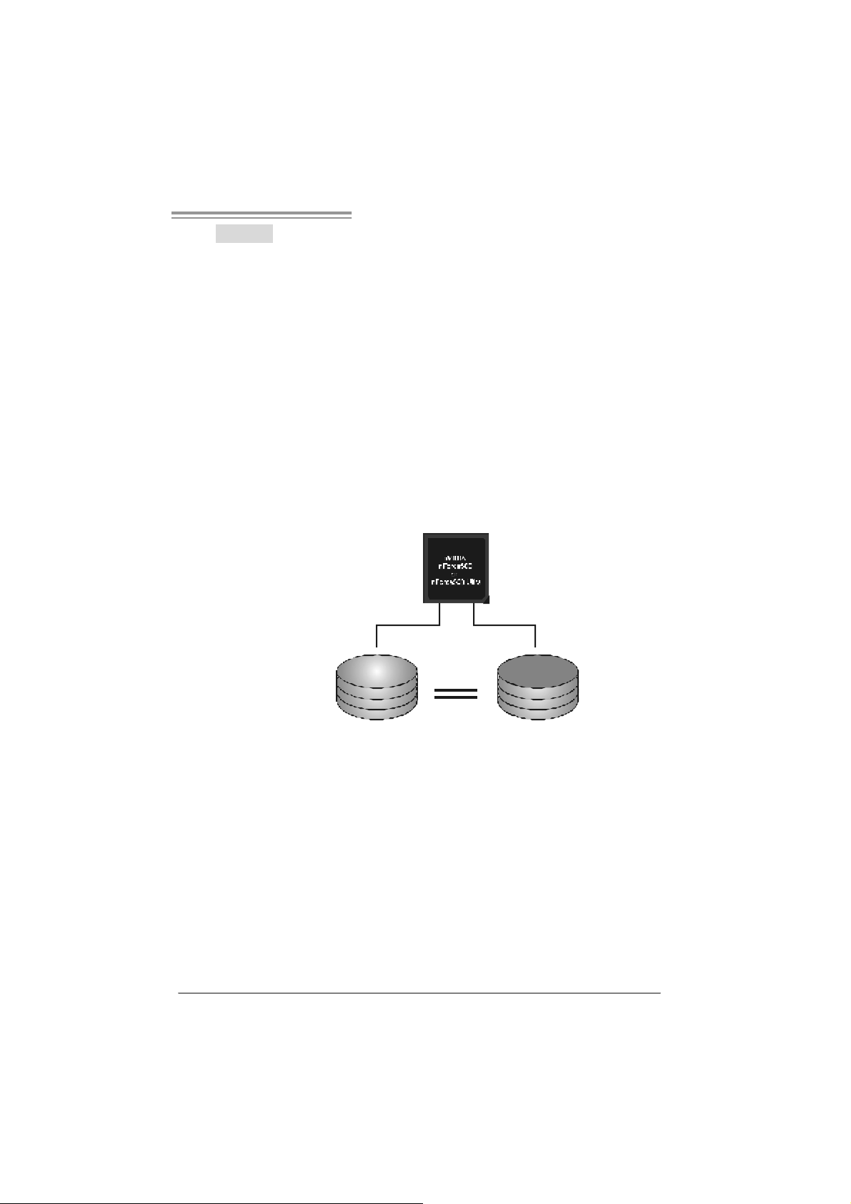
RAID 1:
Every read and write is actually carried out in parallel across 2 disk drives in a RA ID 1
array system. The mirrored (backup) copy of the data can reside on the same disk or on
a second redundant drive in the array. RAID 1 provides a hot-standby copy of data if
the active volume or driv e is co rrupted or beco mes u navailable because of a hardware
failure.
RAID techniques can be applied for high-availability solutions, or as a form of
automatic backup that eliminates tedious manual backups to more expensive and less
reliable media.
Fea tures and Be nefits
Drives: Minimum 2, and maximum is 2.
Uses: RAID 1 is ideal f or small databases or any other application that
requires f ault tolerance and minimal capacity.
Benefits: Prov ides 100% data redundancy. Should one driv e f ail, the
controller switches to the other drive.
Drawbacks: Requires 2 driv es for the storage space of one drive.
Perf ormance is impaired during driv e rebuilds.
Fault To le rance : Yes.
Blo c k 1
Block 2
Block 3
Block 1
Block 2
Block 3
21
Page 24
Motherboard Manual
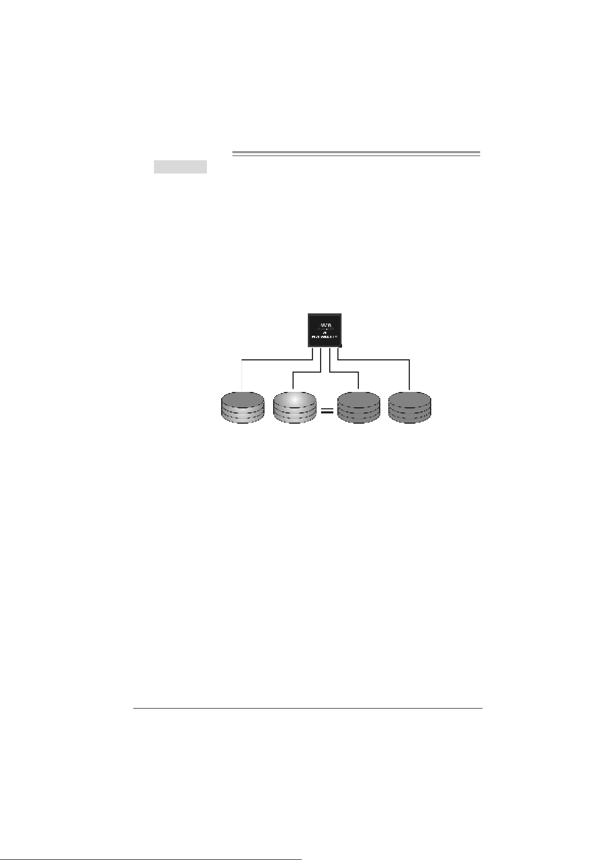
RAID 0+1:
RAID 0 drives can be mirrored using RAID 1 techniques. Resulting in a RAID 0+1
solution for improved performance plus resiliency.
Fea tures and Be nefits
- Drives: Minimum 4, and maximum is 6 or 8, depending on the platform.
- Benefits: Optimizes for both fault tolerance and perf ormance, allowing for
automatic redundancy. May be simultaneously used with other RAID
lev els in an array, and allows f or spare disks.
- Drawbacks: Requires twice the av ailable disk space f or data redundancy,
the same as RAID level 1.
- Faul t Tolerance: Yes.
Block 1
Block 3
Block 5
Block 2
Block 4
Block 6
Block 1
Block 3
Block 5
Block 2
Block 4
Block 6
22
Page 25
NF500 AM2G / NF500 AM2L / NF500U AM2G
RAID 5:
RAID 5 stripes both data and parity information across three or more drives. It writes
data and pa rit y blo cks across all th e driv es in th e arr ay . F aul t to l er ance is mai nt ain ed
by ensuring that the parity in formation for any given block of data is placed on a
different drive from those used to store the data itself.
Features and Benefits
- Drives: Minim um 3.
- Uses: RAID 5 is recommended for transaction processing and general
purpose service.
- Benefits: An ideal c ombination of good performance, good fault tolerance,
and high capacity and storage efficiency.
- Drawbacks: Individual block data transfer rate same as a single disk.
W ri t e p e rf orm a n c e c a n be CP U i n t e ns iv e.
- Fault To le rance : Yes.
Di s k 1
DATA 1
DATA 3
PA RI TY
DATA 7
DATA 9
PA RI TY
Di s k 2
nVidia
n Forc e500
Ultra
DATA 2
PAR ITY
DATA 5
DATA 8
PAR ITY
DATA 11
Di s k 3
PAR ITY
DATA 4
DATA 6
PAR ITY
DATA 10
DATA 12
※ For more detailed setup information, please refer to the Driver CD, or go to
http://www.nvidia.com/page/pg_20011106217193.htm l to download NVIDIA nForce Tutorial Flash.
23
Page 26
Motherboard Manual
CHAPTER 5: USEFUL HELP
5.1 DRIVER INSTALLA TION NOTE
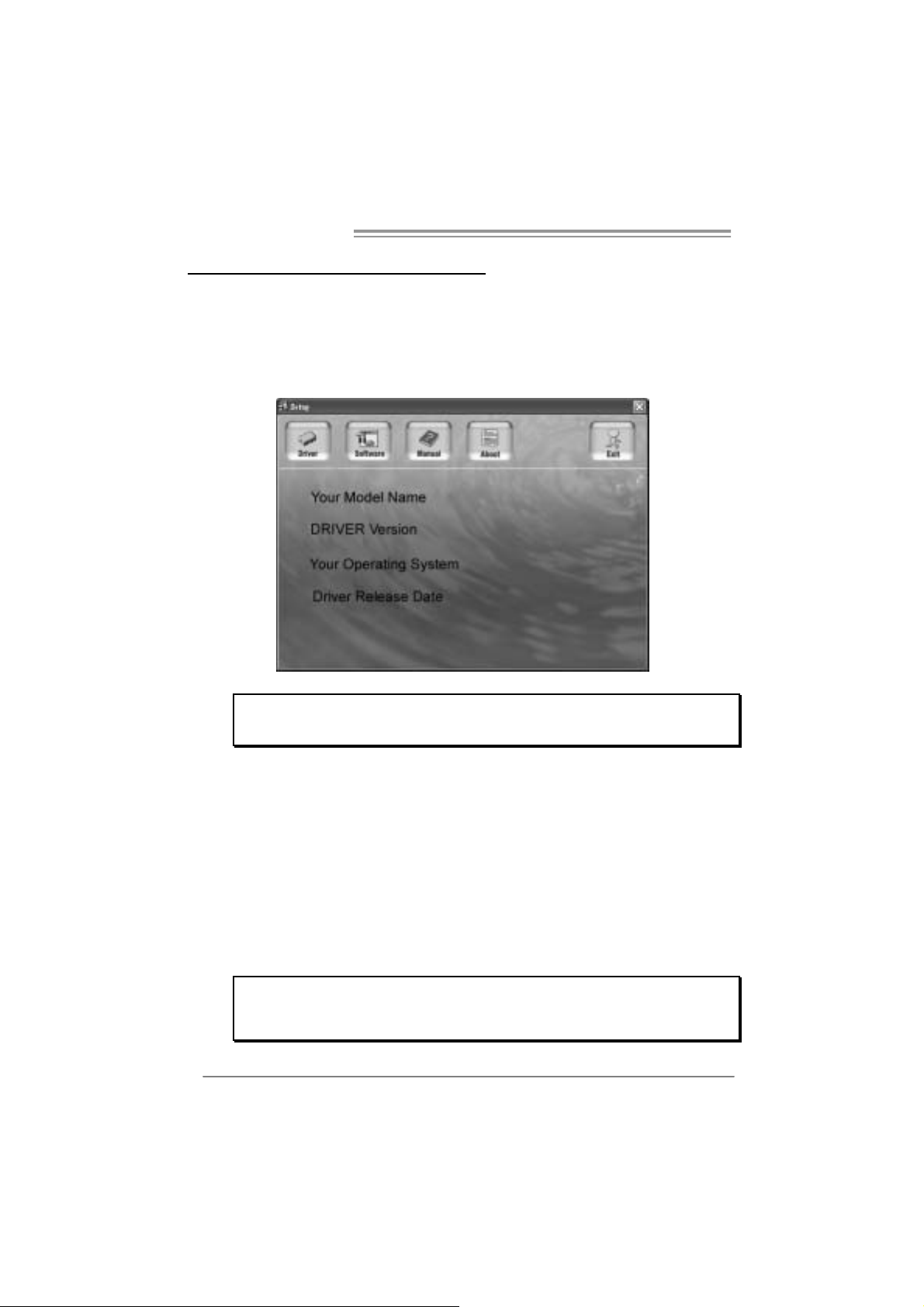
After you installed your operating system, please insert the Fully Setup
Driver CD into your optical drive and install the driver for better system
performance.
You will see the following window after you insert the CD
The setup guide will auto detect your motherboard and operating system .
Note:
If this win do w didn’t sho w up after you ins ert th e Driver CD, ple ase use fi l e br o ws er to
locate and e xecu te th e file SETU P.E XE un der yo ur opti c al drive.
A. Driver Install ation
To install the driver, please click on the Driver icon. The setup guide will
list the compatible driver for your motherboard and operating system.
Click on each device driver to launch the installation program.
B. Software Installation
To install the software, please click on the Software icon. The setup guide
will list the software available for your system, click on each software title
to launch the installation program.
C. Manual
Aside from the paperback manual, we also provide manual in the Driver
CD. Click on the Manual icon to browse for available manual.
Note:
You will need Acrobat Reader to open the manual file. Please download the latest version
of Acrob at Re ad er software fro m
http://www.adobe.com/products/a crobat/readstep2.html
24
Page 27
NF500 AM2G / NF500 AM2L / NF500U AM2G
5.2 AWARD BIOS BEEP CODE
Beep Sound Meanin g
One long beep followed by two s hort
beeps
High-low siren sound CPU overheated
One Short beep when system boot-up No error found during POST
Long beeps every other second No DRAM detected or install
Video card not found or v ideo card
memory bad
System will shut down automatically
5.3 EXT RA INFORMATION
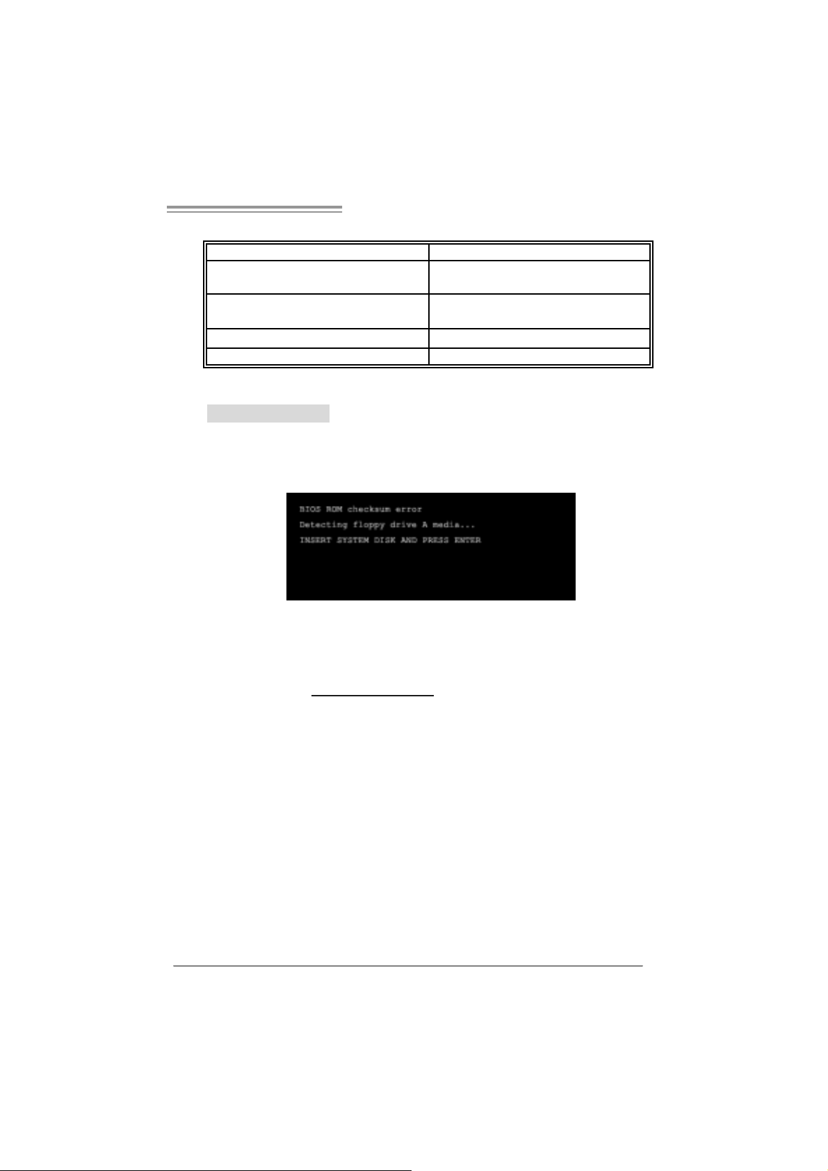
A. BIOS Update
After you fail to update BIOS or BIOS is invaded by virus, the
Boot-Block function will help to restore BIOS. If the following message
is shown after boot-up the system, it means the BIOS contents are
corrupted.
In this Case, please follow the procedure below to restore the BIOS:
1. Make a bootable floppy disk.
2. Download the Flash Utility “AWDFLASH.exe” from the Biostar
website: www.biostar.com.tw
3. Confirm motherboard model and download the respectively BIOS
from Biostar website.
4. Copy “AWDFLASH.exe” and respectively BIOS into floppy disk.
5. Insert the bootable disk into floppy drive and press Enter.
6. System will boot-up to DOS prompt.
7. Type “Awdflash xxxx.bf/ sn/p y/ r” in DOS prompt.
(xxxx means BIOS name.)
8. System will upda te BIOS automatically and restart.
9. T he BIOS has been recovered and will wo rk properl y.
25
Page 28

Motherboard Manual
B. CPU Overheated
If the system shutdown automatically after power on system for
seconds, that means the CPU protection function has been activated.
When the CPU is over heated, the motherboard will shutdown
automatically to avoid a damage of the CPU, and the system may not
power on again.
In this case, please double check:
1. The CPU cooler surface is placed evenly with the CPU surface.
2. CPU fan is rotated normally.
3. CPU fan speed is fulfilling with the CPU speed.
After confirmed, please follow steps below to relief the CPU protection
function.
1. Remove the power cord from power supply for seconds.
2 . Wa i t f o r se c o nd s.
3. Plug in the power cord and boot up the system.
Or you can:
1. Clear the CMOS data.
(See “Close CMOS Header: JCMOS1” section)
2 . Wa i t f o r se c o nd s.
3. P o we r on the syste m ag ai n.
26
Page 29

NF500 AM2G / NF500 AM2L / NF500U AM2G
e
5.4 TROUBLESHOOTING
Probable Solution
1. No power to the system at all
Power light don’t illuminate, fan
inside power supply does not turn
on.
2. Indicator light on key board does
not turn on.
System inoperative. Keyboard lights
are on, power indicator lights are lit,
and hard driv e is spinning.
System does not boot from hard disk
driv e, can be booted f rom optical driv e.
System only boots f rom optical driv e.
Hard disk can be read and applications
can be used but booting from hard disk
is impossible.
Screen message says “Invalid
Configuration” or “C MOS Failure.”
Cannot boot system after installing
second hard driv e.
1. Make sure power cable is
securely plugged in.
2. Replace cable.
3. Cont act technical support.
Using even pressure on both ends of
the DIMM, press down firmly until the
module snaps into place.
1. Check cable running from disk to
disk controller board. Make sure
both ends are securely plugged
in ; c h ec k t h e d r iv e ty pe i n t h e
standard CMOS setup.
2. Backing up the hard drive is
extremely important. All hard
disks are capable of breaking
down at any time.
1. Back up data and applications
files.
2. Reformat the hard driv e.
Re-install applications and data
using backup disks.
Review system’s equipment. Make sur
correct information is in setup.
1. Set master/slave jumpers
correctly.
2. Run SETUP program and select
correct drive types. Call the drive
manufacturers f or compatibility
with other drives.
27
Page 30

Motherboard Manual
CHAPTER 6: WARPSPEED ER™
6.1 INTRODUCTION
[WarpSpeeder™], a new powerful control utility, features three
user-friendly functions including Overclock Manager, Overvoltage
Manager, and Hardware Monitor.
With the Overclock Manager, users can easily adjust the frequency they
prefer or they can get the best CPU performance with just one click. The
Overvoltage Manager, on the other hand, helps to power up CPU core
voltage and Memory voltage. The cool Hardware Monitor smartly indicates
the temperatures, voltage and CPU fan speed as well as the chipset
information. Also, in the About panel, you can get detail descriptions about
BIOS model and chipsets. In addition, the frequency status of CPU,
memory, AGP and PCI along with the CPU speed are synchronically
shown on our main panel.
Moreover, to protect users' computer systems if the setting is not
appropriate when testing and results in system fail or hang,
[WarpSpeeder™] technology assures the system stability by automatically
rebooting the computer and then restart to a speed that is either the
original system speed or a suitable one.
6.2 SYSTEM REQU IREMENT
OS Support: Windows 98 SE, Windows Me, Windows 2000, Windows XP
DirectX: DirectX 8.1 or above. (The Windows XP operating system
includes DirectX 8.1. If you use Windows XP, you do not need to install
DirectX 8.1.)
28
Page 31

NF500 AM2G / NF500 AM2L / NF500U AM2G
6.3 INSTALLATION
1. Execute the setup execution file, and then the following dialog will pop
up. Please click “Next” button and follow the default procedure to
install.
2. When you see the following dialog in setup procedure, it means setup
is completed. If the “Launch the WarpSpeeder Tray Utility” checkbox
is checked, the T ray Ico n utility and [WarpSpeeder™] utility will be
automatically and immediately launched after you click “Finish”
button.
Usage:
The following figures are just only for reference, the screen printed in
thi s user manual will change acco rding to you r motherboard on han d.
29
Page 32

Motherboard Manual
6.4 WARPSPEEDER™
1. Tray Icon:
Whenever the Tray Icon utility is launched, it will displa y a li ttle tray
icon on the right side of Windows Taskbar.
This utility is responsible for conveniently invoking [WarpSpeeder™]
Utility. You can use the mouse by clicking the left button in order to
invoke [WarpSpeeder™] directly from the little tray icon or you can
right-click the little tray icon to pop up a popup menu as following
figure. The “Launch Utility” item in the popup menu has the same
function as mouse left-cli ck on tray icon and “Exit” item will close
Tray Icon utility if selected.
30
Page 33

NF500 AM2G / NF500 AM2L / NF500U AM2G
2. Main Panel
If you click the tray icon, [WarpSpeeder™] utility will be in voked.
Please refer to the following figure; the utility’s first window you will
see is Main Panel.
Main Panel con tai ns feature s as foll ows:
a . Di sp l a y t he CP U Sp ee d , CP U ex t e rnal cl o c k, M em o ry clo c k, AG P cl ock,
and PCI clock information.
b. Contains About, Voltage, Overclock, and Hardware Monitor Buttons for
invoking respective panels.
c. With a user-friendly Status Animation, it can represent 3 overclock
percentage stages:
Man walking→overclock percentage from 100% ~ 110 %
Panther running→overclock percentage from 110% ~ 120%
Car raci ng→overclock percentage from 120% ~ above
31
Page 34

Motherboard Manual
3. Vol tage Panel
Cli ck the Voltage button in Main Panel, the button will be highli ghted
an d the Voltage Panel will slide out to up as the following figure.
In this panel, you can decide to increase CPU core voltage and
Memory voltage or not. The default setting is “No”. If you want to get
the best performance of overclocking, we recommend you click the
option “Yes”.
32
Page 35

NF500 AM2G / NF500 AM2L / NF500U AM2G
4. Over clock Panel
Cli ck the Overcl o ck button in Main Panel, the bu tton will be
highlighted and the Overclock Panel will slide out to left as the
following figure.
Overclock Panel cont ains the these fea tures:
a. “–3MHz button”, “-1MHz button”, “+1MHz button”, and “+3MHz button”:
provide user the ability to do real-time overclock adjustment.
Warning:
Manually overclock is potentially dangerous, especially when the
ov erclocking percentage is over 110 %. We strongly recommend you
v erify ev ery speed you overclock by click the Verify button. Or, you can
just click Auto ov erclock button and let [WarpSpeeder™] automatically
gets the best result f or y ou.
b. “Recovery Dialog button”: Pop up the following dialog. Let user select
a restoring way if system need to do a fail-safe reboot.
33
Page 36

Motherboard Manual
c. “Auto-overclock button”: User can click this button and
[WarpSpeeder™] will set the be st and stable performan ce and
frequency automatically. [WarpSpeeder™] utility will execute a
seri es of te sting until system fail. Then system will do fail -safe
reboot by using Watchdog function. After reboot, the
[WarpSpeeder™] utility will restore to the hardware default
setting or load the verified best and stable frequency according
to the Recovery Dialog’s setting.
d. “Verify button”: User can click this button and [WarpSpeeder™]
will proceed a testing for current frequency. If the testing is ok,
then the current frequency will be saved into system registry. If
the testing fail, system will do a fail-safe rebooting. After reboot,
the [WarpSpeeder™] utility will restore to the hardware default
setting or load the verified best and stable frequency according
to the Recovery Dialog’s setting.
Note:
Because the testing programs, invoked in Auto-overclock and Verify,
include DirectDraw, Direct3D and DirectShow tests, the DirectX 8.1 or
newer runtime library is required. And please make sure y our display
card’s color depth is High color (16 bit ) or True c olor( 24/32 bit ) that is
required f or Direct3D rendering.
5. Hardware Monitor Panel
Cli ck the Hardware Monitor button in Main Panel, the button will be
highlighted and the Hardware Monitor panel will slide out to left as
the following figure.
In this panel, you can get the real-time status information of your
system. The information will be refreshed every 1 second.
34
Page 37

NF500 AM2G / NF500 AM2L / NF500U AM2G
6. About Panel
Click the “about” button in Main Panel, the button will be highlighted
and the About Panel will slide out to up as the following figure.
In this panel, you can get model name and detail information in hints
of all the chipset that are related to overclocking. You can also get
the mainboard’s BIOS model and the Version number of
[WarpSpeeder™] utility.
Note :
Because the overclock, overvoltage, and hardware monitor features
are controlled by several separate chipset, [WarpSpeeder™] divide
these features to separate panels. If one chipset is not on board, the
co rre l at i ve button in Mai n panel will be di sabl ed, bu t wil l no t inte rf ere
other panels’ functions. This property can make [WarpSpeeder™]
utility mo re robust.
35
Page 38

Motherboard Manual
APPENDENCIES: SPEC IN OTHER LANG UAGE
GERMAN
NF50 0 AM2G / NF50 0 AM 2L NF500U AM2 G
Sockel AM2
AM D Athlon 64 / At hlon 64 FX / Althlon 64 X 2/
CPU
FSB
Chipsatz nVIDIA nForce500 nVIDIA nForce 500 Ultra
Super E/A
Ar beitsspeic h
er
IDE
SA TA
LAN
Audi o-Codec
Sempron Prozessoren
Die AMD 64-Architektur unterstützt eine 32-Bit-
und 64-B it-Datenverarbeit ung
Unterstützt Hyper Transport und Cool’n’Quiet
Unterstützt HyperTransport m it ei ner Ba ndbreite
von bis zu 2 GHz
ITE 8716F
Bi etet die häufi g verwendeten alt en Super
E/A-Funktionen.
Low Pin C ount-Schnittstell e
DDR2 DIMM-Steckpl ätze x 4
Jede r DIMM unt erstützt 256/512MB & 1GB
DDR2.
M a x. 4GB A rbeit ss p eic h e r
Dual-Kanal DDR2 Speichermodul
Unt erstützt DDR2 533 / 667 / 800 registrierte
DIMMs. ECC DIMMs werden nicht unterstützt.
Integrierter IDE-Controller
Ultra DMA 33 / 66 / 100 / 133 Bus
Master-Modus
I nt e gri ert e r S e ri al ATA - Con tr o ll e r
Datentransferrate bis zu 1.5Gb/s
Konform mit der SATA-Spezifikation Version 1.0.
Marvell 88E3016 PHY (nur für NF500 AM2L)
10 / 100 Mb/s Auto-Negotiation
Marvell 88E1116 PHY ( nur für NF500 AM2G)
10 / 100 Mb/s und 1Gb/s Aut o-Negotiation
C- media C M 6501
7.1-Kanal-Audioausgabe
Unterstützt USB Audio
Sockel AM2
AM D Athlon 64 / At hlon 64 FX / Althlon 64 X 2/
Sempron Prozessoren
Die AMD 64-Architektur unterstützt eine 32-Bit-
und 64-B it-Datenverarbeit ung
Unterstützt Hyper Transport und Cool’n’Quiet
Unterstützt HyperTransport m it ei ner Ba ndbreite
von bis zu 2 GHz
ITE 8716F
Bi etet die häufi g verwendeten alt en Super
E/A-Funktionen.
Low Pin C ount-Schnittstell e
DDR2 DIMM-Steckpl ätze x 4
Jede r DIMM unt erstützt 256/512MB & 1GB
DDR2.
M a x. 4GB A rbeit ss p eic h e r
Dual-Kanal DDR2 Speichermodul
Unt erstützt DDR2 533 / 667 / 800 registrierte
DIMMs. ECC DIMMs werden nicht unterstützt.
Integrierter IDE-Controller
Ultra DMA 33 / 66 / 100 / 133 Bus
Master-Modus
I nt e gri ert e r S e ri al ATA - Con tr o ll e r
Datentransferrate bis zu 3.0Gb/s
Konform mit der SATA-Spezifikation Version 2.0.
Marvell 88E1116 PHY
10 / 100 Mb/s und 1Gb/s Aut o-Negotiation
C- media C M 6501
7.1-Kanal-Audioausgabe
Unterstützt USB Audio
36
Page 39

NF500 AM2G / NF500 AM2L / NF500U AM2G
NF50 0 AM2G / NF50 0 AM 2L NF500U AM2 G
PCI-St eckplatz x4 PCI-St eckplatz x4
Steckplätze
Onboard-Ans
chluss
Rückseiten-E
/A
Platinengröße
.
Sonderfunkti
onen
OS-Unterstüt
zung
PCI Express x16 Steckplatz x1 PCI Express x16 Steckplatz x1
PCI Express x 1-Steckplatz x2 PCI Express x 1-Steckplatz x2
Di skett e nlaufwer kansc hluss x1 Di skett e nlaufwer kansc hluss x1
Dr uc keranschluss A nschluss x 1 Dr uc keranschl uss A nschluss x1
IDE-A nschluss x2 I DE- A nschluss x2
SATA-Anschluss x4 SATA-Anschluss x4
Fronttafelanschluss x1 Fronttafelanschluss x1
Fr o nt-Audi oansc hluss x1 Fr o nt-Audi oansc hluss x1
CD-IN-Anschl uss x1 CD-IN-Anschl uss x1
S/PDIF-Ausgangsanschluss x1 S/PDIF-Ausgangsanschluss x1
CPU-Lüfter-S ockel x1 CPU-Lüfter-Sockel x1
System-Lüfter-Sockel x2 System-Lüfter-Sockel x2
"CMOS löschen"-Sockel x1 "CMOS löschen"-Sockel x1
US B- A nschluss x2 US B- A nschluss x2
Stromanschluss (24-polig) x1 Stromanschluss (24-polig) x1
Stromanschluss (4-polig) x1 Stromanschluss (4-polig) x1
PS/2-Tastatur x1
PS/2-Maus x1
Seri eller A nsc hluss x1
LAN-Ansc hl uss x1
US B- A nschluss x4
Audi o anschl uss x6
218 mm (B) X 293 mm (L) 218 mm (B) X 293 mm (L)
NVIDIA nTunes
NVIDIA Firewall (nur für NF500 AM2G)
Unterstützt RAID 0 / 1 / 0+1
Windows 2K / XP / VISTA
Biostar behält sich das Recht vor, ohne
Ank ündigung die Unterstützung für ein
Be triebssystem hinzuz ufügen oder zu
entfernen.
PS/2-Tastatur x1
PS/2-Maus x1
Seri eller A nsc hluss x1
LAN-Ansc hl uss x1
US B- A nschluss x4
Audi o anschl uss x6
NVIDIA nTunes
NVIDIA Firewall
Unt erstützt RAID 0 / 1 / 0+ 1 / 5
Windows 2K / XP / VISTA
Biostar behält sich das Recht vor, ohne
Ank ündigung die Unterstützung für ein
Be triebssystem hinzuz ufügen oder zu
entfernen.
37
Page 40

Motherboard Manual
FRANCE
NF50 0 AM 2G / NF50 0 AM 2L NF500U AM2 G
Socket AM2
Pr ocess e urs AM D Athlon 64 / At hl on 64 FX /
UC
Bus frontal
Chi pset nVI DIA nFor c e 500 nVI DI A nForc e 500 Ultra
Super E/S
Mémoire
principale
IDE
SA TA
LAN
Althlon 64 X2 / Sempron
L'architectur e AMD 64 permet le calcul 32 et 64
bits
Prend en c harge Hyper Trans port et Cool’n’Quiet
Prend en charge Hyper Transport jusqu'à une
bande passante de2 GHz
ITE 8716F
Four nit la fonctionnalité de Super E/S
patrimoniales la plus utilisée.
Interface à faible compte de broches
Fentes DDR2 DIMM x 4
Chaque DIMM prend en charge des DDR2 de
256/512 Mo et 1Go
Capacité mémoire maximale de 4 Go
Modul e de mémoire DDR2 à mode à double voie
Prend en charge la DDR2 533 / 667 / 800
Les DIMM à registres et DIMM avec code
correcteurs d' erreurs ne sont pas prises en
charge
Contrôleur I DE intégr é
Mode principale de Bus Ultra DMA 33 / 66 / 100 /
133
Prend en c harge le mode PIO 0~4,
Cont r ôl eur Se rial ATA intégré :
Taux de transfert jusqu'à 1.5 Go/s.
Conforme à la spécification SATA Version 1.0
Marvell 88E3016 PHY (Seulement pour NF500
AM2L)
10 / 100 Mb/s négociation automati que
Marvell 88E1116 PHY (Seulement pour NF500
AM2G)
10 / 100 / 1000 M b/s négociation automatique
38
Socket AM2
Pr ocess e urs AM D Athlon 64 / At hl on 64 FX /
Althlon 64 X2 / Sempron
L'architectur e AMD 64 permet le calcul 32 et 64
bits
Prend en c harge Hyper Trans port et Cool’n’Quiet
Prend en charge Hyper Transport jusqu'à une
bande passante de2 GHz
ITE 8716F
Four nit la fonctionnalité de Super E/S
patrimoniales la plus utilisée.
Interface à faible compte de broches
Fentes DDR2 DIMM x 4
Chaque DIMM prend en charge des DDR2 de
256/512 Mo et 1Go
Capacité mémoire maximale de 4 Go
Modul e de mémoire DDR2 à mode à double voie
Prend en charge la DDR2 533 / 667 / 800
Les DIMM à registres et DIMM avec code
correcteurs d' erreurs ne sont pas prises en
charge
Contrôleur I DE intégr é
Mode principale de Bus Ultra DMA 33 / 66 / 100 /
133
Prend en c harge le mode PIO 0~4,
Cont r ôl eur Se rial ATA intégré :
Taux de transfert jusqu'à 3.0 Go/s.
Conforme à la spécification SATA Version 2.0
Marvell 88E1116 PHY
10 / 100 / 1000 M b/s négociation automatique
Page 41

NF500 AM2G / NF500 AM2L / NF500U AM2G
NF50 0 AM 2G / NF50 0 AM 2L NF500U AM2 G
Codec audio
Connecte ur
embarqué
E/S du
panneau
arrière
Dim ensions
de la carte
Fonctionnali
tés
spéciales
Support SE
C- media C M 6501
Sortie audio à 7. 1 voies
Prise en charge de l'audi o USB
Fente PCI x4 Fente PCI x4
Slot PCI Express x16 x1 Slot PCI Express x16 x1 Fentes
Slot PCI Express x 1 x2 S lot PCI Expres s x 1 x2
Connecteur de disquette x1 Connect eur de disquette x1
Connecteur de Port d'imprimante x1 Connecteur de Port d'imprimante x1
Connecte ur IDE x 2 Connecteur IDE x2
C onnec te ur SATA x4 C o nnect e ur SATA x4
Connecteur du panneau avant x1 C onnect eur du panne au avant x1
Connecteur A udio du panneau avantx1 x1 Connecteur A udio du panneau avantx1 x 1
Connec teur d'entrée CD x1 Connec teur d'entrée CD x1
Connecteur de sortie S/PDIF x1 Connecteur de sortie S/PDIF x1
Embase de ventilateur UC x1 Embase de ventilateur UC x1
Embase de ventilateur système x2 Embase de ventilateur système x2
Embase d'effacem ent CMOS x 1 Embase d'effacement CMOS x1
Connecte ur USB x 2 Connecteur USB x2
Connec teur d'alimentation x1
(24 broc hes)
Connec teur d'alimentation x1
(4 broches)
Clavier PS/2 x1
Souris PS/2 x1
Port s érie x1
Port LAN x1
Port USB x4
Fiche audio x6
218 mm (l) X 293 mm (H) 218 m m (l) X 293 mm (H)
NVIDIA nTunes
Par e-feu NVI DIA (Seulement pour NF500 AM2G)
Prise en c harge RAID 0 / 1 / 0+1
Windows 2K / XP / VISTA
Biostar se réserve le droit d'ajouter ou de
supprimer le support de SE avec ou sans préavis
C- media C M 6501
Sortie audio à 7. 1 voies
Prise en charge de l'audi o USB
Connec teur d'alimentation x1
(24 broc hes)
Connec teur d'alimentation x1
(4 broches)
Clavier PS/2 x1
Souris PS/2 x1
Port s érie x1
Port LAN x1
Port USB x4
Fiche audio x6
NVIDIA nTunes
Pare-feu NVIDIA
Prise en c harge RAID 0 / 1 / 0+1
Windows 2K / XP / VISTA
Biostar se réserve le droit d'ajouter ou de
supprimer le support de SE avec ou sans préavis
39
Page 42

Motherboard Manual
ITALIAN
NF50 0 AM 2G / NF50 0 AM 2L NF500U AM2 G
Socket AM2
Processori AMD Athlon 64 / Athlon 64 FX /
CPU
FSB
Chi ps et nV IDIA nF orce 500 nV I DIA nFor c e 500 U ltr a
Super I/O
Memoria
principal e
IDE
SATA
LAN
Althlon 6 4 X2 / Sempron
L’architettura AMD 64 abilita la
computaz i one 32 e 64 bit
Suppor to di Hyper Tra ns por t e C ool’ n’Quiet
Suppor to di Hyper Trans p or t fi no a2 GHz di
lar ghez z a di ba nda
ITE 871 6F
Fornisce le funzionalità legacy Super I/O
usate più comunemente.
Interfaccia LPC (L ow Pin Count)
Al loggi DI MM DDR 2 x 4
Ciascun DIMM support a DDR 2 256/51 2MB e
1GB
Capacità massima della memoria 4GB
Modul o di memori a DDR2 a c an ale dop pio
Supporto di DDR2 533 / 667 / 800
DIMM registrati e DIMM ECC non sono
support at i
Controller IDE integrato
Modalità Bus Master Ultra DMA 33 / 66 /
100 / 133
Suppor to m odal it à PIO Mode 0- 4
Controller Serial ATA integrato
Ve loc ità di trasferim ento dei dati fi no a 1.5
Gb/s .
Compatibile specifiche SATA Versione 1.0.
Marvell 8 8E301 6 PHY (sol o per NF 50 0
AM2L)
Negoziazione automat ica 10 / 100 M b /s
Marvell 8 8E111 6 PHY (sol o per NF 50 0
AM2G)
Negoziazione automatica 10 / 100 Mb/s e 1Gb/s
40
Socket AM2
Processori AMD Athlon 64 / Athlon 64 FX /
Althlon 6 4 X2 / Sempron
L’architettura AMD 64 abilita la
computaz i one 32 e 64 bit
Suppor to di Hyper Tra ns por t e C ool’ n’Quiet
Suppor to di Hyper Trans p or t fi no a2 GHz di
lar ghez z a di ba nda
ITE 871 6F
Fornisce le funzionalità legacy Super I/O
usate più comunemente.
Interfaccia LPC (L ow Pin Count)
Al loggi DI MM DDR 2 x 4
Ciascun DIMM support a DDR 2 256/51 2MB e
1GB
Capacità massima della memoria 4GB
Modul o di memori a DDR2 a c an ale dop pio
Supporto di DDR2 533 / 667 / 800
DIMM registrati e DIMM ECC non sono
support at i
Controller IDE integrato
Modalità Bus Master Ultra DMA 33 / 66 /
100 / 133
Suppor to m odal it à PIO Mode 0- 4
Controller Serial ATA integrato
Ve loc ità di trasferim ento dei dati fi no a 3.0
Gb/s .
Compatibile specifiche SATA Versione 2.0.
Marvell 8 8E111 6 PHY
Negoziazione automatica 10 / 100 Mb/s e 1Gb/s
Page 43

NF500 AM2G / NF500 AM2L / NF500U AM2G
NF50 0 AM 2G / NF50 0 AM 2L NF500U AM2 G
Codec
audio
Alloggi
Connet tori
su scheda
I/O
pannello
posteri ore
Dim ens i on
i scheda
Caratterist
iche
speciali
Sistemi
operativi
support at i
C- media C M 6501
Uscita audio 7.1 canali
Suppor to au dio US B
Alloggio PCI x4 Alloggio PCI x4
Al loggio PCI Ex press x1 6 x1 Alloggio PCI Ex pres s x1 6 x1
Al loggio PCI Ex press x1 x2 Al loggio PCI Ex press x1 x2
Connet t ore fl o ppy x 1 Connet t or e flo ppy x1
Connet tore Port a stampa nte x1 Connet t or e Port a s t am pa nte x1
Connet tore I DE x 2 Connet t or e IDE x2
Connet tore S A TA x4 C onnettore SA TA x4
Connet tore pa nnell o fro nt ale x1 Connet t or e pa nnel lo fro nt ale x1
Connettore audio frontale x1 Connettore audio frontale x1
Connettore CD-in x1 Connettore CD-in x1
Connettore output SPDIF x1 Connettore output SPDIF x1
Collettore ventolina CPU x1 Collettore ventolina CPU x1
Collettore ventolina sistema x2 Collettore ventolina sistema x2
Collettore cancellazione CMOS x1 Collettore cancellazione CMOS x1
Connet tore USB x2 Conne ttore USB x2
Connettore alimentazione x1
(24 pin)
Connettore alimentazione x1
(4 pin)
Ta s t i e ra P S/ 2 x 1
Mouse PS/2 x1
Porta seriale x1
Porta LAN x1
Porta USB x4
Connet tore au dio x 6
21 8 mm (largh ez z a) x 29 3 mm ( al tez z a) 218 mm (l ar gh ezz a) x 29 3 mm (altez z a)
nTunes NV I DIA
Firewall NVIDIA (solo per NF500 AM2G)
Supporto R A ID 0 / 1 / 0+ 1
Windows 2K / XP / VISTA
Biostar si riserva il diritto di aggiungere o
rimuovere il supporto di qualsiasi sistema
operativo s e nza pre avviso
C- media C M 6501
Uscita audio 7.1 canali
Suppor to au dio US B
Connettore alimentazione x1
(24 pin)
Connettore alimentazione x1
(4 pin)
Ta s t i e ra P S/ 2 x 1
Mouse PS/2 x1
Porta seriale x1
Porta LAN x1
Porta USB x4
Connet tore au dio x 6
nTunes NV I DIA
Firewa ll NVIDIA
Supporto R A ID 0 / 1 / 0+ 1 / 5
Windows 2K / XP / VISTA
Biostar si riserva il diritto di aggiungere o
rimuovere il supporto di qualsiasi sistema
operativo s e nza pre avviso
41
Page 44

Motherboard Manual
SPANISH
NF50 0 AM 2G / NF50 0 AM 2L NF500U AM2 G
CPU
FSB
Conjunto de
chips
Súper E/S
Memoria
principal
IDE
SA TA
Red Local
Conector AM2
Procesadores AMD Athlon 64 / Athlon 64 FX /
Athlon 64 X2 / Sempron
La arquitectura AMD 64 permite el procesado de
32 y 64 bi ts
Soporta las tecnologías Hyper Transport y
Cool’n’Quiet
Admite HyperTransport con un ancho de banda
de hasta2 GHz
nVI DI A nForc e 500 nVIDI A nForc e500 Ult ra
ITE 8716F
Le ofrece las funcionalidades heredadas de uso
más común Súper E/S.
Interfaz de cuenta Low Pin
Ranuras DIMM DDR2 x 4
Cada DIMM admit e DDR de 256/512MB y 1GB
Capaci dad máxima de memoria de 4GB
Módul o de memoria DDR2 de canal Doble
Admite DDR2 de 533 / 667 / 800
No admite DIMM registrados o DIMM
compatibles con ECC
Controlador IDE integrado
Modo bus maestr o Ultra DMA 33 / 66 / 100 / 133
Soporte los Modos PIO 0~4,
Controlador ATA Serie Integrado
Tasas de transferencia de hasta 1.5 Gb/s.
Compatible con la versión SATA 1.0.
Marvell 88E3016 PHY (solame nte para NF500
AM2L)
Negociaci ón de 10 / 100 Mb/s
Marvell 88E1116 PHY (solame nte para NF500
AM2G)
Negociaci ón de 10 / 100 / 1000 Mb/s
Conector AM2
Procesadores AMD Athlon 64 / Athlon 64 FX /
Athlon 64 X2 / Sempron
La arquitectura AMD 64 permite el procesado de
32 y 64 bi ts
Soporta las tecnologías Hyper Transport y
Cool’n’Quiet
Admite HyperTransport con un ancho de banda
de hasta2 GHz
ITE 8716F
Le ofrece las funcionalidades heredadas de uso
más común Súper E/S.
Interfaz de cuenta Low Pin
Ranuras DIMM DDR2 x 4
Cada DIMM admit e DDR de 256/512MB y 1GB
Capaci dad máxima de memoria de 4GB
Módul o de memoria DDR2 de canal Doble
Admite DDR2 de 533 / 667 / 800
No admite DIMM registrados o DIMM
compatibles con ECC
Controlador IDE integrado
Modo bus maestr o Ultra DMA 33 / 66 / 100 / 133
Soporte los Modos PIO 0~4,
Controlador ATA Serie Integrado
Tasas de transferencia de hasta 3.0 Gb/s.
Compatible con la versión SATA 0.0.
Marvell 88E1116 PHY
Negociaci ón de 10 / 100 / 1000 Mb/s
42
Page 45

NF500 AM2G / NF500 AM2L / NF500U AM2G
NF50 0 AM 2G / NF50 0 AM 2L NF500U AM2 G
Códecs de
sonido
Conectores
en placa
Panel
trasero de
E/S
Ta m a ñ o de
la plac a
Funciones
especiales
Soporte de
sistema
operativo
C- media C M 6501
Salida de sonido de 7.1 canales
Soporte de sonido USB
Ranura PCI X4 Ranura PCI X4
Ranura PCI Express x16 X1 Ranura PCI Express x16 X1 Ranuras
Ranura PCI express x 1 X2 Ranura PCI express x 1 X2
Conector disco flexible X1 Conector disco flexible X1
C o nec t or Pu er t o de im p r es or a X 1 C o nec t or Pu er t o de im p r es or a X 1
Conector IDE X2 Conector IDE X2
C onec t or SATA X 4 C o nec tor SATA X4
Conect or de panel frontal X1 Conect or de panel frontal X1
Conector de sonido frontal X1 Conector de sonido frontal X1
Conector de entrada de CD X1 Conector de entrada de CD X1
Conector de salida S/PDIF X1 Conector de salida S/PDIF X1
Cabecera de ventilador de CPU X1 Cabecera de ventilador de CPU X1
Cabecera de ventilador de sistema X2 Cabecera de ventilador de sistema X2
Cabecera de borrado de CMOS X1 Cabecera de borrado de CMOS X1
Conector USB X2 Conector USB X2
Conector de alimentación X1
(24 pat illas)
Conector de alimentación X1
(4 patillas)
Te c l ado PS / 2 X 1
Ratón PS/2 X1
Puerto serie X1
Puerto de r ed local X1
Puerto USB X 4
Conector de sonido X6
218 mm. (A) X 293 M m. (H) 218 mm. (A) X 293 Mm. (H)
NVIDIA nTunes
NVIDIA Firewall (solamente para NF500 AM2G)
Admite RAI D 0 / 1 / 0+1
Windows 2K / XP / VISTA
Biostar se reserva el derecho de añadir o retirar
el soporte de cualquier SO con o sin aviso previo
C- media C M 6501
Salida de sonido de 7.1 canales
Soporte de sonido USB
Conector de alimentación X1
(24 pat illas)
Conector de alimentación X1
(4 patillas)
Te c l ado PS / 2 X 1
Ratón PS/2 X1
Puerto serie X1
Puerto de r ed local X1
Puerto USB X 4
Conector de sonido X6
NVIDIA nTunes
NVIDIA Firewall
Admite RAI D 0 / 1 / 0+1 / 5
Windows 2K / XP / VISTA
Biostar se reserva el derecho de añadir o retirar
el soporte de cualquier SO con o sin aviso previo
43
Page 46

Motherboard Manual
PORTUGUESE
NF50 0 AM 2G / NF50 0 AM 2L NF500U AM2 G
Socket AM2
Processadores AMD Athlon 64 / Athlon 64 FX /
Althlon 64 X2 / Sempron
CPU
FSB
Chi pset nVI DIA nFor c e 500 nVI DI A nForc e 500 Ultra
Es pecificaçã
o Super I/O
Memória
principal
IDE
SA TA
LAN
A ar quit ect ura AM D 64 perm ite uma c om putaç ão
de 32 e 64 bits
Suporta as tecnologias Hyper Transport e
Cool’n’Quiet
Suporta a tecnologia HyperTransport com uma
largura de banda até2 GHz
ITE 8716F
Proporciona as funcionalidades mais utilizadas
em termos da especificação Super I/O.
Int erface LPC (Low Pin Count).
Ranhuras DIMM DDR2 x 4
Cada módulo DIMM suporta uma memória
DDR2 de 256/512 MB & 1 GB
Capaci dade máxima de memória: 4 GB
Módul o de memória DDR2 de canal duplo
Suporta módul os DDR2 533 / 667 / 800
Os módulos DIMM registados e os DIMM ECC
não são suportados
Controlador IDE integrado
Modo B us mast er Ultra DMA 33 / 66 / 100 / 133
Suporta o modo PIO 0~4,
Controlador Serial ATA integrado
Velocidades de transmissão de dados até 1.5
Gb/s.
Compatibilidade com a especificação SATA
v e rs ã o 1. 0.
Marvell 88E3016 PHY (apenas para os modelos
NF500 A M 2L)
Auto negociação de 10 / 100 Mb/s.
Marvell 88E1116 PHY (apenas para os modelos
NF500 A M 2G)
Auto negociação de 10 / 100 / 1000 Mb/s.
Socket AM2
Processadores AMD Athlon 64 / Athlon 64 FX /
Athlon 64 X2 / Sempron
A ar quit ect ura AM D 64 perm ite uma c om putaç ão
de 32 e 64 bits
Suporta as tecnologias Hyper Transport e
Cool’n’Quiet
Suporta a tecnologia HyperTransport com uma
largura de banda até2 GHz
ITE 8716F
Proporciona as funcionalidades mais utilizadas
em termos da especificação Super I/O.
Int erface LPC (Low Pin Count).
Ranhuras DIMM DDR2 x 4
Cada módulo DIMM suporta uma memória
DDR2 de 256/512 MB & 1 GB
Capaci dade máxima de memória: 4 GB
Módul o de memória DDR2 de canal duplo
Suporta módul os DDR2 533 / 667 / 800
Os módulos DIMM registados e os DIMM ECC
não são suportados
Controlador IDE integrado
Modo B us mast er Ultra DMA 33 / 66 / 100 / 133
Suporta o modo PIO 0~4,
Controlador Serial ATA integrado
Velocidades de transmissão de dados até 3.0
Gb/s.
Compatibilidade com a especificação SATA
v e rs ã o 2. 0.
Marvell 88E1116 PHY
Auto negociação de 10 / 100 / 1000 Mb/s.
44
Page 47

NF500 AM2G / NF500 AM2L / NF500U AM2G
NF50 0 AM 2G / NF50 0 AM 2L NF500U AM2 G
Codec de
som
Conectores
na placa
Entradas/S
aídas no
painel
traseiro
Tamanho
da placa
Característi
cas
especiais
Sistemas
operativos
suportados
C- media C M 6501
Saída de áudio de 7. 1 canais
Suporta a especificação USB Audio
Ranhura PCI x4 R anhura PCI x4
Ranhura PCI Express x16 x1 Ranhura PCI Expr ess x16 x1 R anhuras
Ranhura PCI Express x 1 x2 Ranhura PCI Express x 1 x2
Conect or da unidade de disquetes x1 C onector da unidade de dis quetes x1
Conector da para impr essora x1 Conector da para impressora x1
Conector IDE x2 Conector IDE x2
C onec t or SATA x4 C onec t or SATA x 4
Conect or do painel frontal x1 Conect or do painel frontal x1
Conector de áudio frontal x1 C onect or de áudio frontal x1
Conector para entrada de CDs x1 Conec tor para entrada de CDs x1
Conector de saída S/PDIF x1 Conector de saída S/PDIF x1
Conector da v entoinha da CPU x1 Conect or da ventoinha da CPU x1
Conector da v entoinha do sistema x2 Conector da v entoinha do sistema x2
Conector para limpeza do CMOS x1 Conector para limpeza do CMOS x1
Conector USB x2 Conector USB x2
Conector de alimentação x1
(24 pinos)
Conector de alimentação x1
(4 pinos )
Te c l ado PS / 2 x 1
Rato PS/2 x1
Port a sé ri e x1
Porta LAN x1
Porta USB x4
Tomada de áudio x6
218 mm (L) X 293 mm (A) 218 m m (L) X 293 mm (A)
nTunes da NVIDIA
Firewall da NVIDIA (apenas para os modelos
NF500 A M 2G)
Suporta as funções RAID 0 / 1 / 0+1
Windows 2K / XP / VISTA
A Biostar reserva-se o direito de adicionar ou
remover suporte para qualquer sis tema
operativo com ou sem aviso prévio.
C- media C M 6501
Saída de áudio de 7. 1 canais
Suporta a especificação USB Audio
Conector de alimentação x1
(24 pinos)
Conector de alimentação x1
(4 pinos )
Te c l ado PS / 2 x 1
Rato PS/2 x1
Port a sé ri e x1
Porta LAN x1
Porta USB x4
Tomada de áudio x6
nTunes da NVIDIA
Firewall da NVIDIA
Suporta as funções RAID 0 / 1 / 0+1 / 5
Windows 2K / XP / VISTA
A Biostar reserva-se o direito de adicionar ou
remover suporte para qualquer sis tema
operativo com ou sem aviso prévio.
45
Page 48

Motherboard Manual
POLISH
NF50 0 AM 2G / NF50 0 AM 2L NF500U AM2 G
Socket AM2
AM D Athlon 64 / At hlon 64 FX / At hlon 64 X2 /
Procesor
FSB
Chi pset nVI DIA nFor c e 500 nVI DI A nForc e 500 Ultra
Pamięć
główna
Super I/O
IDE
SA TA
LAN
Sem pron Procesory
Arc hitektura AMD 64 um ożliwi a przetwarzani e
32 i 64 bi t owe
Obsługa Hyper Transport oraz Cool’n’Quiet
Obsługa HyperTransport o szerokości pasma do2
GHz
Gniaz da DDR 2 DIMM x 4
Każ de gniazdo DIMM obsługuje m oduły
256/512MB oraz 1GB DDR2
Maks. wielkość pami ęci 4GB
Moduł pam ięci DDR 2 z trybem podwójnego
kanału
Obsługa DDR2 533 / 667 / 800
Brak obsługi Registered DIMM oraz ECC DIMM
ITE 8716F
Zapewnia najbardziej powszechne funkcje Super
I/O.
Int erfejs Low Pin Count
Z i nt e g ro w an y k o nt r ol e r I D E
Ultra DMA 33 / 66 / 100 / 133 Tryb Bus Master
obsługa PIO try b 0~4
Zintegrowany kontroler Serial ATA
Transfer danych do 1.5 Gb/s.
Zgodność ze specyfikacją SATA w wersji 1.0.
Marvell 88E3016 PHY (wyłącznie dla NF500
AM2L)
10 / 100 Mb/s oraz automatyczną negocjacją
szybkości
Marvell 88E1116 PHY (wyłącznie dla NF500
AM2G)
10 / 100 / 1000 M b/s oraz automatyczną
negoc jacją szybkości
46
Socket AM2
AM D Athlon 64 / At hlon 64 FX / At hlon 64 X2 /
Sem pron Procesory
Arc hitektura AMD 64 um ożliwi a przetwarzani e
32 i 64 bi t owe
Obsługa Hyper Transport oraz Cool’n’Quiet
Obsługa HyperTransport o szerokości pasma do2
GHz
Gniaz da DDR 2 DIMM x 4
Każ de gniazdo DIMM obsługuje m oduły
256/512MB oraz 1GB DDR2
Maks. wielkość pami ęci 4GB
Moduł pam ięci DDR 2 z trybem podwójnego
kanału
Obsługa DDR2 533 / 667 / 800
Brak obsługi Registered DIMM oraz ECC DIMM
ITE 8716F
Zapewnia najbardziej powszechne funkcje Super
I/O.
Int erfejs Low Pin Count
Z i nt e g ro w an y k o nt r ol e r I D E
Ultra DMA 33 / 66 / 100 / 133 Tryb Bus Master
obsługa PIO try b 0~4
Zintegrowany kontroler Serial ATA
Transfer danych do 3.0 Gb/s.
Zgodność ze specyfikacją SATA w wersji 2.0.
Marvell 88E1116 PHY
10 / 100 / 1000 M b/s oraz automatyczną
negoc jacją szybkości
Page 49

NF500 AM2G / NF500 AM2L / NF500U AM2G
NF50 0 AM 2G / NF50 0 AM 2L NF500U AM2 G
Kodek
dźwięko wy
Złącza
wbudowane
Back Panel
I/O
Wymiary
płyty
Funkcje
specjalne
Obsluga
systemu
operacyjne
go
C- media C M 6501
7.1 kanałow e w y jście aud io
Obsługa USB Audio
Gniazdo PCI x4 Gniaz do PCI x4
Gniazdo PCI Express x16 x1 Gniazdo PCI Express x16 x1 Gniazda
Gniazdo PCI Express x 1 x2 Gniazdo PCI Express x 1 x2
Złącze na pędu dyskietek x1 Złącze napędu dyskietek x1
Złącze Port drukarki x1 Z łącze Port drukarki x1
Złącze I DE x2 Złącze I DE x2
Złącz e SA TA x4 Z łącz e SA TA x4
Złącze panela przedniego x1 Złącze panela przedniego x1
Przednie złą cz e audio x1 Przedni e złą cze a udio x1
Złącz e w ejścia C D x1 Złącze w ejścia C D x1
Złącz e w yjści a S / PDIF x1 Z łącz e w yjścia S /P DIF x1
Złącze głów ko we w ent ylat or a pr oc es o ra x1 Z łącz e głów kow e w ent yl at o r a pr oc es o ra x1
Złącze głów ko we w ent ylat o ra
systemowego x2
Złącze głów kow e kas ow ani a
CMOS x1
Złącze USB x 2 Z łącz e USB x2
Złącze z asilani a (24 p inowe) x1 Złącze zasil ania ( 24 pinowe ) x 1
Złącze z asilani a (4 pi now e) x1 Z łącz e z asilani a (4 pi nowe ) x 1
Klawiatura PS/2 x1
Mysz PS/2 x1
Port szeregowy x1
Port LAN x1
Port USB x4
Gniazdo audio x6
218mm (S) X 293 mm (W) 218mm (S) X 293 mm ( W)
NVIDIA nTunes.
NVIDIA Firewall (wyłączni e dla NF500 AM2G)
Obsługa RAID 0 / 1 / 0+1
Windows 2K / XP / VISTA
Bi ostar zastrze ga s obie prawo dodawania lub
odwoływania obsługi dowolnego systemu
o p er ac y j n ego be z po w i ad om i eni a.
C- media C M 6501
7.1 kanałow e w y jście aud io
Obsługa USB Audio
Złącze głów ko we w ent ylat o ra
systemowego x2
Złącze głów kow e kas ow ani a
CMOS x1
Klawiatura PS/2 x1
Mysz PS/2 x1
Port szeregowy x1
Port LAN x1
Port USB x4
Gniazdo audio x6
NVIDIA nTunes.
NVIDIA Firewall
Obsługa RAID 0 / 1 / 0+1 / 5
Windows 2K / XP / VISTA
Bi ostar zastrze ga s obie prawo dodawania lub
odwoływania obsługi dowolnego systemu
o p er ac y j n ego be z po w i ad om i eni a.
47
Page 50

Motherboard Manual
RUSSIAN
NF50 0 AM 2G / NF50 0 AM 2L NF500U AM2 G
Гнездо AM2
Процессоры AM D At hlo n 64 / At hlon 6 4 F X /
Athlon 64 X2 / Sempron
Архитектура AMD 64 разрешать обработка
данны х на 32 и 64 бит
Поддержка Hyper Transport и Cool’n’Q ui et
Поддержка HyperTransport с пропус кной
способностью до2GГц
Слоты DDR2 DIMM x 4
Каждый модуль DIMM поддерживает
256/512МБ & 1ГБ DDR2
Максимальная ём к ос т ь пам яти 4 ГБ
Модуль пам яти с двухканальным режимом
DDR2
Поддержка DDR2 533 / 667 / 800
Не поддерживает з арегистрированные
модули DIMM and ECC DIMM
ITE 8716F
Обеспечивает наиболее ис п о ль з у е м ы е
действующие функциональные возможности
Super I/O.
Интерфейс с низ ким количеством вы в о до в
Вс троенное ус тр о й с тво управления
встроенными интерфейсам и устройств
Режим "хозяина" шины Ultra DMA 33 / 66 / 100
/ 133
Поддержка режима PIO 0~4,
Вс троенное последовательное ус тройство
управления ATA
скорость передачи данных до 3.0 гигабит/с.
Соответствие с пецификац ии SA TA версия 2. 0.
Marvell 88E1116 PHY
Автоматическ ое согласование 10 / 100 / 1000
Мб/с .
CPU
(центральн
ый
проц ессор)
FSB
Набор
микрос хем
Основная
память
Super I/O
IDE
SA TA
Локальная
сеть
48
Гнездо AM2
Процессоры AM D At hlo n 64 / At hlon 6 4 F X /
Althlon 64 X2 / Sempron
Архитектура AMD 64 разрешать обработка
данны х на 32 и 64 бит
Поддержка Hyper Transport и Cool’n’Q ui et
Поддержка HyperTransport с пропус кной
способностью до2GГц
nVI DI A nForc e 500 nVIDI A nForc e500 Ult ra
Слоты DDR2 DIMM x 4
Каждый модуль DIMM поддерживает
256/512МБ & 1ГБ DDR2
Максимальная ём к ос т ь пам яти 4 ГБ
Модуль пам яти с двухканальным режимом
DDR2
Поддержка DDR2 533 / 667 / 800
Не поддерживает з арегистрированные
модули DIMM and ECC DIMM
ITE 8716F
Обеспечивает наиболее ис п о ль з у е м ы е
действующие функциональные возможности
Super I/O.
Интерфейс с низ ким количеством вы в о до в
Вс троенное ус тр о й с тво управления
встроенными интерфейсам и устройств
Режим "хозяина" шины Ultra DMA 33 / 66 / 100
/ 133
Поддержка режима PIO 0~4,
Вс троенное последовательное ус тройство
управления ATA
скорость передачи данных до 1.5 гигабит/с.
Соответствие с пецификац ии SA TA версия 1. 0.
Marvell 88E3016 PHY (только для NF500 AM2L)
Автоматическ ое согласование 10 / 100 Мб/с .
Marvell 88E1116 PHY (только для NF500 AM2G)
Автоматическ ое согласование 10 / 100 / 1000
Мб/с .
Page 51

NF500 AM2G / NF500 AM2L / NF500U AM2G
NF50 0 AM 2G / NF50 0 AM 2L NF500U AM2 G
Звуковой
кодек
Вс троенны
й разъём
Задняя
панель
средств
ввода-вы в
ода
Размер
панели
Специальн
ые
технически
е
характерис
тики
Поддержка
OS
C- media C M 6501
7. 1канальный звуковой выход
Звуковая поддержка USB
Слот PCI x2 Слот PCI x2
Слот PCI Express x16 x1 Слот PCI Express x16 x1 Слоты
Слот PCI Express x 1 x1 Слот PCI Express x 1 x1
Разъём НГМД x1 Разъём НГМД x1
Разъём Порт подключе ния принтера x1 Разъём Порт подключения принтера x1
Разъём IDE x2 Разъём IDE x2
Разъём SATA x4 Разъём SATA x 4
Разъём на лиц евой панели x1 Разъём на лицевой панели x1
Входной звуковой разъём x1 Входной звуковой разъём x1
Разъём ввода для CD x1 Разъём ввода для CD x1
Разъём вы в о д а для S/PDIF x1 Разъём вы в о д а для S/PDIF x1
Контактирующее прис пособление
вентилятора центрального проц ессора x1
Контактирующее прис пособление
вентилятора системы x2
Открытое контак т и р ую ще е
прис пособление CMOS x1
USB-разъём x2 USB-разъём x2
Разъем питания (24 вы в о д ) x 1 Разъем питания (24 вы в о д ) x 1
Разъем питания (4 вы в о д) x 1 Разъем питания (4 вы в од) x 1
Клавиатура PS/2 x1
Мышь PS / 2 x1
Последовательный порт x1
Порт LAN x1
USB-порт x4
Гнездо для подключе ния наушников x6
218 мм (Ш) X 293 мм (В) 218 мм (Ш) X 293 мм (В)
NVIDIA nTunes
NVIDIA Firewall (только для NF500 AM2G)
Поддержка RAID 0 / 1 / 0+ 1
Windows 2K / XP / VISTA
Biostar сохраняет за собой право добавлять
или удалять средства обеспечения для OS с
или без предваритель ного уведомления.
C- media C M 6501
7. 1канальный звуковой выход
Звуковая поддержка USB
Контактирующее прис пособление
вентилятора центрального проц ессора x1
Контактирующее прис пособление
вентилятора системы x2
Открытое контак т и р ую ще е
прис пособление CMOS x1
Клавиатура PS/2 x1
Мышь PS / 2 x1
Последовательный порт x1
Порт LAN x1
USB-порт x4
Гнездо для подключе ния наушников x6
NVIDIA nTunes
NVIDIA Firewall
Поддержка RAID 0 / 1 / 0+ 1 / 5
Windows 2K / XP / VISTA
Biostar сохраняет за собой право добавлять
или удалять средства обеспечения для OS с
или без предваритель ного уведомления.
49
Page 52

Motherboard Manual
/
/
ARABIC
ﺲﺒﻘﻡAM2
تﺎ ﺠﻟﺎ ﻌﻡ AMD Athlon 64
Athlon 64 X2 / Sempron
ﺔ ﻴﻨﻘ ﺗ ﻦﻜﻤﺗ AM D 64 ﺔﻋﺮﺴﺏ ﺔﻴﺏﻮﺳﺎﺤﻟا تﺎﻴﻠﻤﻌﻟا ءاﺮﺝ إ 32 و64 ﺖﺏ
ﺔ ﻴﻨﻘﺗ ﻢﻋ ﺪ ﺗ Hyper Transport و Cool’n’Quiet
ﻢﻋﺪﺗ ﺔ ﻴﻨﻘ ﺗ HyperTransport ددﺮﺘﺏ ﻞﺼﻳ ﻰﻟإ 2G ددﺮﺗ
ﺔﺤﺘﻓ ﻞآ ﻢﻋ ﺪﺗ DIM M عﻮﻥ ﻦﻡ ةﺮآ اذ ﻢﻋ ﺪﺗ DDR2 ﺔﻌﺳ 256/512 ﺎﺠﻴﻡ
عﻮﻥ ﻦﻡ ةﺮ آ اﺬﻟا ﻢﻋ ﺪ ﺗ DDR2 تﺎﻌﺳ 533 / 667 / 800 ﺏ ﺎﺠﻴﻡ ﺖﻳﺎ
ةﺮآ اﺬﻟا ﻖﺋﺎﻗر ﻢﻋﺪﺗ ﻻDIMM ﻊﻡ ﻖﻓاﻮﺘ ﺗ ﻻ ﻲﺘﻟا ﻚﻠﺗ و ECC
ﺔﻔﻴﻇو ﺮﻓﻮﺗSuper I/O ًﺎﻡا ﺪ ﺨ ﺘ ﺳ ا ﺮﺜ آ ﻷا .
ﺗﻢﻋ ﺪ ﺔﻴﻨﻘﺗ
ﺔ ﻴﻨﻘﺘ ﺏ ﻞﻗﺎﻥUltra DMA 33 / 66 / 100 / 133
تﺎﻔﺹاﻮﻤﻟ ﺔﻘﺏﺎﻄﻡSATA راﺪﺹﻹا 2. 0.
Athlon 64 FX /
ىﻮﺼﻗ ةﺮآاذ ﺔﻌﺳ4 ﺖﻳ ﺎﺏ ﺎﺠﻴ ﺝ
ةﺮآ اذ ةﺪﺣوDDR2 ﻘﻟا ﺔﺝودﺰﻡةﺎﻨ
ITE 8716F
Low Pin C ount Interface
ﻢﻜﺤﺘﻡIDEﻞﻡﺎﻜﺘﻡ
ﻲﺴﻴﺋر ﻊﺿ و
ﻢﻜﺤﺘﻡSerial ATAﻞﻡﺎﻜﺘﻡ
ﻰﻟإ ﻞﺼﺗ تﺎﻋﺮﺴﺏ تﺎﻥ ﺎﻴﺒﻟا ﻞﻘﻥ3. 0 ﺖﺏ ﺎﺠ ﻴﺝ/ﺔﻴ ﻥﺎﺙ.
Marvell 88E1116 PHY
ﻲﺋﺎﻘﻠﺗ ضوﺎﻔﺗ10/100 / 1000 ﺖﻳ ﺎﺏ ﺎﺠﻴﻡ /و ﺔﻴﻥﺎﺙ
C- media C M 6501
7. 1 تاﻮﻨﻗ جﺮﺨﻟ تﻮﺼﻟا
USB Audio
NF50 0 AM 2G / NF50 0 AM 2L NF500U AM2 G
تﺎ ﺠﻟﺎ ﻌﻡ AMD Athlon 64 / Athlon 64 FX
Althlon 64 X2 / Sempron
ﺔ ﻴﻨﻘ ﺗ ﻦﻜﻤﺗ AM D 64 ﺔﻋﺮﺴﺏ ﺔﻴﺏﻮﺳﺎﺤﻟا تﺎﻴﻠﻤﻌﻟا ءاﺮﺝ إ 32 و64 ﺖﺏ
ﺔ ﻴﻨﻘﺗ ﻢﻋ ﺪ ﺗ Hyper Transport و Cool’n’Quiet
ﺔﺤﺘ ﻓDDR2 DIMM دﺪﻋ4
ﺔﺤﺘﻓ ﻞآ ﻢﻋ ﺪﺗ DIM M عﻮﻥ ﻦﻡ ةﺮآ اذ ﻢﻋ ﺪﺗ DDR2 ﺔﻌﺳ 256/512 ﺎﺠﻴﻡ
و ﺖﻳﺎﺏ1 ﺎﺠﻴﺝﺖﻳﺎﺏ
ةﺮآ اذ ةﺪﺣوDDR2 ﻘﻟا ﺔﺝودﺰﻡةﺎﻨ
عﻮﻥ ﻦﻡ ةﺮ آ اﺬﻟا ﻢﻋ ﺪ ﺗ DDR2 تﺎﻌﺳ 533 / 667 / 800ﺖﻳﺎ ﺏ ﺎﺠﻴﻡ
ﻻ ةﺮآ اﺬﻟا ﻖﺋﺎﻗر ﻢﻋ ﺪﺗ DIMM ﻊﻡ ﻖﻓاﻮﺘ ﺗ ﻻ ﻲﺘﻟا ﻚﻠﺗ و EC C
ﺔﻔﻴﻇو ﺮﻓﻮﺗSuper I/O ًﺎﻡا ﺪ ﺨ ﺘ ﺳ ا ﺮﺜ آ ﻷا .
ﺗﻢﻋ ﺪ ﺔﻴﻨﻘﺗ Low Pin C ount Interfac e
ﺔ ﻴﻨﻘﺘ ﺏ ﻞﻗﺎﻥUltra DMA 33 / 66 / 100 / 133
ﻢﻜﺤﺘﻡSerial ATAﻞﻡﺎﻜﺘﻡ
ﻰﻟإ ﻞﺼﺗ تﺎﻋﺮﺴﺏ تﺎﻥ ﺎﻴﺒﻟا ﻞﻘﻥ1. 5 ﺖﺏﺎﺠ ﻴﺝ/ﺔﻴ ﻥﺎﺙ.
تﺎﻔﺹاﻮﻤﻟ ﺔﻘﺏﺎﻄﻡSATA راﺪﺹﻹا 1. 0.
Marvell 88E3016 PHY ( ﻲــــﻓ NF500 AM2L ﻂ ـــــﻘﻓ)
Marvell 88E1116 PHY ( ﻲــــﻓ NF500 AM2G ﻂـــــﻘﻓ)
C- media C M 6501
7. 1 تاﻮﻨﻗ جﺮﺨﻟ تﻮﺼﻟا
ﺲﺒﻘﻡAM2
ﺔﺤﺘ ﻓDDR2 DIMM دﺪﻋ4
و ﺖﻳﺎﺏ1 ﺎﺠﻴﺝﺖﻳﺎﺏ
ىﻮﺼﻗ ةﺮآاذ ﺔﻌﺳ4 ﺖﻳ ﺎﺏ ﺎﺠﻴ ﺝ
ITE 8716F
ﻢﻜﺤﺘﻡIDEﻞﻡﺎﻜﺘﻡ
ﻲﺴﻴﺋر ﻊﺿ و
ﻲﺋﺎﻘﻠﺗ ضوﺎﻔﺗ10/100 ﺖﻳﺎﺏ ﺎﺠﻴ ﻡ /و ﺔﻴﻥﺎ ﺙ
ﻲﺋﺎﻘﻠﺗ ضوﺎﻔﺗ10/100 / 1000 ﺠﻴﻡ ﺖﻳ ﺎ ﺏ ﺎ /و ﺔﻴﻥﺎﺙ
USB Audio
ﺎﻌﻤﻟا ةﺪﺣو ﺔﺠﻟ
ﺔﻳﺰآﺮﻤ ﻟا
ﻲﺒ ﻥ ﺎﺠ ﻟا ﻲﻡ ﺎﻡ ﻷا ﻞﻗﺎﻨﻟا ﻢﻋﺪﺗ ﺔ ﻴﻨﻘ ﺗ HyperTransport ددﺮﺘﺏ ﻞﺼﻳ ﻰﻟإ 2G ددﺮﺗ
ﺢﺋ اﺮﺸﻟا ﺔﻋﻮﻤﺠﻡ nVI DI A nForc e 500 nVIDIA nForce 500 Ultra
ﺔﻴﺴ ﻴﺋﺮﻟا ةﺮ آ اﺬ ﻟا
Super I/O
ﺬﻔ ﻨﻡIDE
SATA
ﺔﻴﻠﺥ اد ﺔﻜﺒﺵ
تﻮﺼ ﻟا ﻚﻳ دﻮ آ
50
Page 53

NF500 AM2G / NF500 AM2L / NF500U AM2G
NVIDIA nTunes
NVIDIA Firewall
ﺔ ﻴﻨﻘﺗ ﻢﻋ ﺪ ﺗ RAID 0 / 1 / 0+1 / 5
Windows 2K / XP / VISTA
ﻆﻔ ﺘﺤﺗ Biostar وأ رﺎ ﻄﺥ ﺈ ﺏ ﻞﻴﻐﺸﺗ مﺎﻈﻥ يﻷ ﻢﻋ ﺪﻟ ا ﺔﻟازإ وأ ﺔﻓﺎﺿإ ﻲﻓ ﺎﻬﻘﺤﺏ
ﺢﻴﺗﺎﻔﻡ ﺔﺣﻮﻟPS/2 دﺪﻋ1
سوﺎﻡ PS/2 دﺪﻋ1
ﻲﻠﺴﻠﺴﺗ ﺬﻔﻨﻡ دﺪﻋ1
ﺼﺗا ﺔﻜ ﺒﺵ ﺬﻔﻨﻡﺔﻴﻠ ﺤﻡ لﺎ دﺪﻋ1
ﺬﻓﺎﻨ ﻡUSB دﺪﻋ4
تﻮﺹ ﺲﺒﻘﻡ دﺪﻋ6
218 ﻢﻡ)ضﺮﻋ( X 293 ﻢﻡ)عﺎ ﻔ ﺗر ا(
رﺎ ﻄﺥ إ نوﺪﺏ.
NF50 0 AM 2G / NF50 0 AM 2L NF500U AM2 G
ﺔﻥﺮ ﻡ صاﺮﻗأ كﺮﺤﻡ ﺬﻔﻨﻡ دﺪﻋ1 ﺔﻥﺮ ﻡ صاﺮﻗأ كﺮﺤﻡ ﺬﻔﻨﻡ دﺪﻋ1
ﺔﻴ ﻡﺎ ﻡﻷ ا ﺔﺣﻮﻠﻟا ﺬﻔﻨﻡ دﺪﻋ1 ﺔﻴ ﻡﺎ ﻡﻷ ا ﺔﺣﻮﻠﻟا ﺬﻔﻨﻡ دﺪﻋ1
ﻲﻡﺎﻡﻷا تﻮﺼﻟا ﺬﻔﻨﻡ دﺪﻋ1 ﻲﻡﺎﻡﻷا تﻮﺼﻟا ﺬﻔﻨﻡ دﺪﻋ1
ﺔﻳﺰآ ﺮ ﻤﻟ ا ﺔﺠﻟﺎﻌﻤﻟا ةﺪﺣو ﺔﺣو ﺮ ﻡ ﺔﻠﺹو دﺪﻋ1 و ﺔﺣو ﺮ ﻡ ﺔﻠﺹوﺔﻳﺰآ ﺮ ﻤﻟ ا ﺔﺠﻟﺎﻌﻤﻟا ةﺪﺣ دﺪﻋ1
مﺎﻈﻨﻟا ﺔﺣوﺮ ﻡ ﺔﻠﺹو دﺪﻋ2 مﺎﻈﻨﻟا ﺔﺣوﺮ ﻡ ﺔﻠﺹو دﺪﻋ2
ﺔﻗﺎﻄﻟا ﻞﻴﺹﻮﺗ ﺬﻔﻨﻡ)24سﻮﺏد( دﺪﻋ1 ﺔﻗﺎﻄﻟا ﻞﻴﺹﻮﺗ ﺬﻔﻨﻡ)24سﻮﺏد( دﺪﻋ1
ﺔﻗﺎﻄﻟا ﻞﻴﺹﻮﺗ ﺬﻔﻨﻡ)4ﺲ ﻴﺏﺎ ﺏد( دﺪﻋ 1 ﺔﻗﺎﻄﻟا ﻞﻴﺹﻮﺗ ﺬﻔﻨﻡ)4ﺲ ﻴﺏﺎ ﺏد( دﺪﻋ1
ﺔﻴﻠ ﺤﻡ لﺎ ﺼ ﺗا ﺔﻜ ﺒ ﺵ ﺬﻔﻨﻡ دﺪﻋ1
تﻮﺹ ﺲﺒﻘﻡ دﺪﻋ6
NVIDIA nTunes
NVIDIA Firewall ( ﻲــــﻓ NF 500 AM2G ﻂـــــﻘ ﻓ )
ﺔ ﻴﻨﻘﺗ ﻢﻋ ﺪ ﺗ RAID 0 / 1 / 0+1
Windows 2K / XP / VISTA
ﻆﻔ ﺘﺤﺗ Biostar وأ رﺎ ﻄﺥ ﺈ ﺏ ﻞﻴﻐﺸﺗ مﺎﻈﻥ يﻷ ﻢﻋ ﺪﻟ ا ﺔﻟازإ وأ ﺔﻓﺎﺿإ ﻲﻓ ﺎﻬﻘﺤﺏ
ﺔﺤﺘ ﻓPCI دﺪﻋ4 ﺔﺤﺘ ﻓPCI دﺪﻋ4
ﺔﺤﺘ ﻓx16 PCI Express ﻋ دﺪ1 ﺔﺤﺘ ﻓx16 PCI Express دﺪﻋ1
تﺎ ﺤﺘﻔ ﻟا
ﺔﺤﺘ ﻓP CI Express x 1 دﺪﻋ2 ﺔﺤﺘ ﻓP CI Express x 1 دﺪﻋ2
ﺔﻌﺏ ﺎﻃ ﺬﻔﻨﻡ دﺪﻋ1 ﺔﻌﺏ ﺎﻃ ﺬﻔﻨﻡ دﺪﻋ1
ﺬﻔﻨﻡIDE دﺪﻋ2 ﺬﻔﻨﻡIDE دﺪﻋ2
ﺬﻔﻨﻡSATA دﺪﻋ4 ﺬﻔﻨﻡ SATA دﺪﻋ4
ﺬﻔﻨﻡCD-IN دﺪﻋ1 ﺬﻔﻨﻡCD-IN دﺪﻋ1
ﺢﻄﺳ ﻰﻠﻋ ﺬﻓﺎﻨﻤﻟا
جﺮﺥ ﺬﻔﻨﻡS/PD IF دﺪﻋ1 جﺮﺥ ﺬﻔﻨﻡS/PD IF دﺪﻋ1
ﺔﺣﻮﻠﻟا
ﺢﺴﻡ ﺔﻠﺹوCMOS دﺪﻋ1 ﺢﺴﻡ ﺔﻠﺹوCMOS دﺪﻋ1
ﺬﻔﻨﻡUSB دﺪﻋ2 ﺬﻔﻨﻡUSB دﺪﻋ2
ﺢﻴﺗﺎﻔﻡ ﺔﺣﻮﻟPS/2 دﺪﻋ1
سوﺎﻡ PS/2 دﺪﻋ1
ﻲﻠﺴﻠﺴﺗ ﺬﻔﻨﻡ دﺪﻋ1
ﻞﺥد ﺬﻓﺎﻨﻡ/ جﺮﺥ
ﺔﻴﻔﻠﺨﻟا ﺔ ﺣﻮﻠﻟا
ﺬﻓﺎﻨ ﻡUSB دﺪﻋ4
ﺔﺹﺎﺥ ﺎﻳاﺰﻡ
218 ﻢﻡ)ضﺮﻋ (X 293 ﻢﻡ)عﺎ ﻔ ﺗر ا(
ﺔﺣﻮﻠﻟا ﻢﺠ ﺣ
ﻞﻴﻐﺸﺘﻟا ﺔﻤﻈﻥأ ﻢﻋد
رﺎ ﻄﺥ إ نوﺪﺏ.
51
Page 54

Motherboard Manual
JAPANESE
NF50 0 AM 2G / NF50 0 AM 2L NF500U AM2 G
Socket AM2
AM D Athlon 64 / At hlon 64 FX / Althlon 64 X 2 /
Sempron プロセッ サ
CPU
FSB
チッ プセット nVI DI A nForc e 500 nVIDI A nForc e500 Ult ra
メイ ンメモリ
Super I/O
IDE
SA TA
LAN
サウ ンド
Codec
AMD 64アーキテクチャでは、 32ビットと 64ビット計
算が 可能です
ハイ パートラン スポートと クールアン ドクワイア ット
をサ ポートしま す
2GHz のバ ンド幅まで ハイパート ランスポー トをサポ
ート します
DDR2 DI MMス ロット x 4
各DIMMは 256/512MB & 1GB DDR2をサポート
最大 メモリ容量 4GB
デュ アル チャンネ ルモード DDR2メモリモ ジュール
DDR2 533 / 667 / 800をサポ ート
登録 済み DI M M とECC DIMMはサポートさ れません
ITE 8716F
もっ とも一般に 使用される レガシー Super I/O機能を
採用 しています 。
低ピ ンカウント インターフ ェイス
統合 IDEコン トローラ
Ultra DMA 33 / 66 / 100 / 133バス マスタモー ド
統合 シリアルATAコントローラ
最高 1. 5 Gb /秒 のデータ転 送速度
SA TAバ ージョン 1. 0 仕様に準拠 。
Marvell 88E3016 PHY (NF500 AM 2L のみ )
10 / 100 Mb/秒のオート ネゴシエー ション
Marvell 88E1116 PHY (NF500 AM 2G のみ )
10 / 100 / 1000M b /秒のオー トネゴシエ ーション
C- media C M 6501
7. 1チ ャンネルオ ーディオア ウト
USB A udio
Socket AM2
AM D Athlon 64 / At hlon 64 FX / At hlon 64 X2 /
Sempron プロセッ サ
AMD 64アーキテクチャでは、 32ビットと 64ビット計
算が 可能です
ハイ パートラン スポートと クールアン ドクワイア ット
をサ ポートしま す
2GHz のバ ンド幅まで ハイパート ランスポー トをサポ
ート します
DDR2 DI MMス ロット x 4
各DIMMは 256/512MB & 1GB DDR2をサポート
最大 メモリ容量 4GB
デュ アル チャンネ ルモード DDR2メモリモ ジュール
DDR2 533 / 667 / 800をサポ ート
登録 済み DI M M とECC DIMMはサポートさ れません
ITE 8716F
もっ とも一般に 使用される レガシー Super I/O機能を
採用 しています 。
低ピ ンカウント インターフ ェイス
統合 IDEコン トローラ
Ultra DMA 33 / 66 / 100 / 133バス マスタモー ド
統合 シリアルATAコントローラ
最高 3. 0 Gb /秒 のデータ転 送速度
SA TAバ ージョン 2. 0 仕様に準拠 。
Marvell 88E1116 PHY
10 / 100 / 1000M b /秒のオー トネゴシエ ーション
C- media C M 6501
7. 1チ ャンネルオ ーディオア ウト
USB A udio
52
Page 55

NF500 AM2G / NF500 AM2L / NF500U AM2G
NF50 0 AM 2G / NF50 0 AM 2L NF500U AM2 G
PCIスロット x4 PCIスロット x4
PCI Express x16スロット x1 PCI Express x16スロット x1 スロ ット
PCI Express x 1スロット x2 PCI Express x 1スロット x2
フロ ッピーコネ クタ x1 フロ ッピーコネ クタ x1
プリ ンタポート コネクタ x1 プリ ンタポート コネクタ x1
IDEコネクタ x2 IDEコネクタ x2
SA TAコ ネクタ x4 SATAコ ネクタ x4
フロ ントパネル コネクタ x1 フロ ントパネル コネクタ x1
フロ ントオーデ ィオコネク タ x1 フロ ントオーデ ィオコネク タ x1
オン ボードコ
ネク タ
背面 パネル
I/O
ボー ドサイズ 218 mm (幅) X 293 mm (高さ) 218 m m (幅) X 293 mm (高さ )
特殊 機能
OSサポート
CDインコネクタ x1 CDインコネク タ x1
S/PDIFア ウトコネク タ x1 S/PDIFアウトコネク タ x1
CPUファ ンヘッダ x1 CPUファ ンヘッダ x1
シス テムファン ヘッダ x2 シス テムファン ヘッダ x2
CMOSクリアヘッ ダ x1 CMOSクリアヘッ ダ x1
USBコネクタ x2 USBコネクタ x2
電源 コネクタ (24ピン) x1 電源 コネクタ (24ピン) x1
電源 コネクタ (4ピン ) x1 電源 コネクタ (4ピン) x1
PS/2キー ボード x1
PS/2マウ ス x1
シリ アルポート x1
LANポート x1
USBポート x4
オー ディオジャ ック x6
NVIDIA nTunes
NV IDIA F irewall (N F500 A M2G のみ )
RAID 0 / 1 / 0+ 1 のサポート
Windows 2K / XP / VISTA
Biostarは事前 のサポート なしにOS サポートを 追加ま
たは 削除する権 利を留保し ます。
PS/2キー ボード x1
PS/2マウ ス x1
シリ アルポート x1
LANポート x1
USBポート x4
オー ディオジャ ック x6
NVIDIA nTunes
NVIDIA Firewall
RAID 0 / 1 / 0+ 1 / 5 のサポート
Windows 2K / XP / VISTA
Biostarは事前 のサポート なしにOS サポートを 追加ま
たは 削除する権 利を留保し ます。
2006/11/28
53
Page 56

NF500 AM2G / NF500 AM2L / NF500U AM2G
BIOS SETUP
BIOS Setup .................................................................................................1
1 Main Menu...............................................................................................3
2 Standard CMOS Features......................................................................6
3Advanced BIOS Features........................................................................8
4 Advanced Chipset Features..................................................................13
5 Integrated Peripherals..........................................................................20
6 Power Management Setup....................................................................26
7 PnP/PCI Configurations.......................................................................30
8 PC Health Status...................................................................................33
9 Frequency/ Voltage Control .................................................................35
i
Page 57

NF500 AM2G / NF500 AM2L / NF500U AM2G
BIOS Setup
Introducti on
The purpose of this manual is to describe the settings in the Award™ BIOS
Setup program on this motherboard. The Setup program allows users to modify
the basic system configuration and save these settings to CMOS RAM. The
power of CMOS RAM is supplied by a battery so that it retains the Setup
information when the power is turned off.
Basic Input-Output System (BIOS) determines what a computer can do without
accessing programs from a disk. This system controls most of the input and
output devices such as keyboard, mouse, serial ports and disk drives. BIOS
acti vates at t he first stage o f the boot ing proces s, loading and execut ing the
operating system. Some additional features, such as virus and password
protection or chipset fine-tuning options are also included in BIOS.
The rest of this manual will to guide you through the options and settings in
BIOS Setup.
Plug and Pla y Support
This AWARD BIOS supports the Plug and Play Version 1.0A specifi cation and
ESCD (Extended System Configuration Data) write.
EPA Green PC Support
This AWARD BIOS supports Version 1.03 of the EPA Green PC specification.
APM Su pport
This AWARD BIOS supports Version 1.1&1.2 of the Advanced Power
Management (APM) specification. Power management features are
implemented via the System Management Interrupt (SMI). Sleep and Suspend
power management modes are supported. Power to the hard disk drives and
video monitors can also be managed by this AW ARD BIOS.
ACPI Support
Award ACPI BIOS support Version 1.0 of Advanced Configuration and Power
interface specifi cation (ACPI). It provides ASL code for power management
and device con figuration capabilities as defined in the ACPI specifi cation,
developed by Microsoft, Intel and T oshiba.
PCI Bus Supp ort
This AWARD BIOS also supports Version 2.1 of the Intel PCI (Peripheral
Component Interconnect) local bus specification.
1
Page 58

NF500 AM2G / NF500 AM2L / NF500U AM2G
DRAM S upport
DDR SDRAM (Double Data Rate Synchronous DRAM) is supported.
Supported CP Us
This AWARD BIOS supports the AMD CPU.
Using Se tup
Use the arrow keys to highli ght item s in most of the place, press <Enter> to
select, use the <PgUp> and <PgDn> keys to change entries, press <F1> for help
and press <Esc> to quit. The following table provides more detail about how to
navigate in the Setup program by using the keyboard.
Keystroke Function
Up arrow M ove to pr e vio us it em
Down arro w Move to n e xt item
Left arr o w M ove to th e i te m on th e left (me nu b ar )
Rig ht arr ow Move to the ite m on the rig ht ( me nu bar)
Move E nter Move to th e ite m you desired
Pg U p ke y Increas e the nu mer i c val ue or m a ke c ha ng es
Pg D n ke y Decr eas e the n um er i c val u e or ma k e chang es
+ Ke y Increas e the nu meri c val ue or ma ke c ha nges
- Ke y Decr ease th e num eric v al u e or ma ke ch anges
Esc key Main Men u – Quit and not s ave c ha nges int o CMOS
F1 key General help on Setup navigation keys
F5 key Loa d pr e vious values fro m CMOS
F7 ke y Loa d the opti miz e d defa ults
F10 key Sa ve all th e CM OS c ha ng es a nd exit
Stat us P ag e Setu p M en u and Op ti on Page Setup M en u – E xit
Current page and r eturn to M ain Me nu
2
Page 59

NF500 AM2G / NF500 AM2L / NF500U AM2G
1 Main Menu
Once you enter Award BIOS™ CMOS Setup Utility, the Main Menu will
appear on the screen. T he Main Menu allows you to select from several setup
fun ctions. Use the arrow keys to select among the items and press <Enter> to
accept and enter the sub-menu.
Figure 1: Main Menu
!! WARNING !!
For better system performance, the BIOS firmware is being
continuously updated. The BIOS information described in
this manual (Fi gu re 1, 2, 3, 4, 5, 6, 7, 8, 9 ) is for your
reference only. T he actual BIOS information and settings on
board may be slightly different from this manual.
Standard CMOS Features
This submenu contains industry standard configur able options.
Advanced BIOS Features
This submenu allows you to configure advanced features of the BIOS.
Advanced Chipset Features
This submenu allows you to configure special chipset features.
3
Page 60

NF500 AM2G / NF500 AM2L / NF500U AM2G
Integrated Peripherals
This submenu allows you to configure certain IDE hard drive options and
Programmed Input/ Output features.
Power Management Setup
This submenu allows you to configure the power management features.
PnP/PCI Configuratio ns
This submenu allows you to configure certain “ Plug and Play” and PCI options.
PC Health Status
This submenu allows you to monitor the hardware of your system.
Frequenc y/ Voltage Control
This submenu allows you to change CPU Vcore Voltage and CPU/PCI clock.
(However, we suggest you to use the default setting. Changing the voltage and
clock improperly may damage the CPU or M/B!)
Load O ptimized Defaults
This selection allows you to reload the BIOS when problem occurs during
system booting sequence. These configurations are factory settings optimized
fo r this system. A confirmation message will be displayed before d efaults are
set.
Set Supervisor Password
Setting the supervisor password will prohibit everyone except the supervisor
from making changes using the CMOS Setup Utility. You will be prompted with
to enter a password.
4
Page 61

NF500 AM2G / NF500 AM2L / NF500U AM2G
Set User Password
If the Supervisor Password is not set, then the User Password will function in
the same way as the Supervisor Password. If the Supervisor Password is set and
the User Password is set, the “User” will only be able to view configurations but
will not be able to change them.
Save & Exit Setup
Save all configuration changes to CMOS (memory) and exit setup. Confirmation
message will be displayed before proceeding.
Exit Without Sa ving
Abandon all changes made during the current session and exit setup.
Confirmation message will be displayed befo re proceeding.
Upgrade BIOS
This submenu allows you to upgrade bios.
5
Page 62

NF500 AM2G / NF500 AM2L / NF500U AM2G
2 Standard CMOS Features
The items in Standard CMOS Setup Menu are divided into several categories.
Each category includes no, one or more than one setup items. Use the arrow
keys to highlight the item and then use the<PgUp> or <PgDn> keys to select the
value you want in each item.
Figure 2: Standard CMOS Setup
Main Men u Selecti ons
This table shows the items and the available options on the Main Menu.
Item Options Description
Date mm : dd : yy
Time hh : mm : ss
IDE Channel 0 Master
IDE Channel 0 Slav e
Options are in its sub
menu.
Options are in its sub
menu.
6
Set the system date. Note
that the ‘Day ’ automatically
changes when you set the
date.
Set the system internal
clock.
Press <Enter> to enter the
sub menu of detailed
options
Press <Enter> to enter the
sub menu of detailed
options.
Page 63

NF500 AM2G / NF500 AM2L / NF500U AM2G
Item Options Description
IDE Channel 1 Master
IDE Channel 1 Slav e
Drive A
Drive B
Halt On
Base Memory N/A
Extended Memory N/A
Tot al Mem ory N/A
Options are in its sub
Options are in its sub
360K, 5.25 in
1.2M, 5.25 in
720K, 3.5 in
1.44M, 3.5 in
2.88M, 3.5 in
All Errors
No Errors
All, but Key board
All, but Diskette
All, but Disk/ Key
menu.
menu.
None
Press <Enter> to enter the
sub menu of detailed
options.
Press <Enter> to enter the
sub menu of detailed
options.
Select the type of f loppy
disk drive installed in your
sy stem.
Select the situation in which
y ou want the BIOS to st op
the POST process and
notify y ou.
Displays the amount of
conventional memory
detected during boot up.
Displays the amount of
extended memory detected
during boot up.
Displays the total memory
av ailable in the system.
7
Page 64

NF500 AM2G / NF500 AM2L / NF500U AM2G
3Advanced BIOS Features
Figure 3: Advanced BIOS Setup
Cache Setup
8
Page 65

NF500 AM2G / NF500 AM2L / NF500U AM2G
CPU Interna l Cache
Depending on the CP U/chipset in use, you may be able to increase memory
access time with this option.
Enabl ed (default) Enable cache.
Disabled D isable cache.
External Cache
This option enables o r disables “ Level 2” secondary cache o n th e CPU, which
may improve performance.
Enabl ed (default) Enable cache.
Disabled D isable cache.
Boot Seq & Flop py Setup
This item allows you to setup boot sequence & Floppy.
9
Page 66

NF500 AM2G / NF500 AM2L / NF500U AM2G
Hard Dis k Bo ot Priorit y
The BIOS will attempt to arrange the Hard Disk boot sequence automatically.
You can change the Hard Disk booting sequence here.
The Ch oices: Pri. Master, Pri. Slave, Sec. Master, Sec. Slave, USB HDD0, USB
HDD1, USB HDD2, and Bootable Add-in Cards.
First/Second/Third Boot Dev ice
The BIOS will attempt to load the operating system in this order.
The Choices: Floppy, LS120, Hard Disk, CDROM, ZIP100, USB-FDD,
USB-ZIP, USB-CDROM, Legacy LAN, Disabled.
Boot Other Dev ice
When enabled, BIOS will try to load the operating system from other device
when it failed to load from the three devices above.
The Choices: Enabled (default ), Disabled
Swap Floppy Drive
For systems with two floppy drives, this option allows you to swap logical
drive assignments.
The Choices: Disabled (default), Enabled.
Boot Up Floppy Seek
When enabled, System will test the floppy drives to determine if they have 40
or 80 tracks during boot up. Disabling this option reduces the time it takes to
boot-up.
The Choices: Enabled (defaul t ), Dis abl ed.
10
Page 67

NF500 AM2G / NF500 AM2L / NF500U AM2G
Virus Warning
This option allows you to choose the VIRUS Warning feature that is used to
protect the IDE Hard Disk boot sector. If this function is enabled and an attempt
is made to write to the boot sector, BIOS will display a warning message on the
screen and sound an alarm beep.
Disabled (default) Virus protection is disabled.
Enabled Virus prot ection is activated.
Quick Power On Self Test
Enabling this option will cause an abridged version of the Power On Self-Test
(POST ) to execute after you power up the computer.
Disabled Normal POST.
Enabled (default) Enable quick P OST .
Boot Up NumLock Status
Selects t he NumLock S tate after the syst em switched on.
T he Choices:
On (default) Numpad is number keys.
Off Numpad is arrow keys.
Gate A20 Option
Select if chipset or keyboard controller should control Gate A20.
Normal A pin in the keyboard controller controls GateA20.
Fast (default) Lets chipset control Gate A20.
Typematic Rate Setting
When a key is held down, the keystroke will repeat at a rate determined by the
keyboard controller. When enabled, the typematic rate and typematic delay can
be configured.
The Ch oices: Disab led (defaul t ), Enabled.
Typematic Rate (Chars/Sec)
Sets the rate at which a keystroke is repeated when you hold the key down.
The Ch oices: 6 (default), 8, 10, 12, 15, 20, 24, 30.
Typematic Delay (Msec)
Sets the delay time after the key is held down before it begins to repeat the
keystroke.
The Ch oices: 250 (default ), 500, 750, 1000.
11
Page 68

NF500 AM2G / NF500 AM2L / NF500U AM2G
Security Option
This option will enable only individuals with passwords to bring the system
online and/or to use the CMOS Setup Utility.
System: A password is required for the system to boot and is also
required to access the Setup Utility.
Setup (default ): A password is requi red to access the S etup Utility only.
This will only apply if passwords are set from the Setup main menu.
API C MO DE
Selecting Enabled enables APIC device mode reporting from the BIOS to the
operating system.
The Ch oices: Enabled (defaul t), Disabled.
MPS Version Control For OS
The BIOS supports version 1.1 and 1.4 of the Intel multiprocessor speci fication.
Select version supported by the operation system running on this computer.
The Ch oices: 1. 4 (default), 1.1.
OS Select For DRAM > 64MB
A choice other than Non-OS2 is only used fo r OS2 systems with memory
exceeding 64MB.
The Ch oices: Non -OS 2 (default), OS2.
Summary Screen Show
This item allows you to enable/disable the summary screen. Summary screen
means system configuration and PCI device listing.
The Ch oices: Disab led (defaul t ), Enabled.
12
Page 69

NF500 AM2G / NF500 AM2L / NF500U AM2G
4 Advanced Chipset Features
T his submenu allows you to configure the speci fic features o f the chi pset
installed on your system. T his chipset manage bus speeds and access to sys tem
memory resources, such as DRAM. It also coordinates communications with the
PCI bus. The default settings that came with your system have been optimized
and therefore should not be changed unless you are suspicious that the settings
have been changed incorrectly.
Figure 4: Advanced Chipset Setup
K8<->NB HT Spe ed
This item allows you to select HT Frequency.
The Ch oices: Auto (Default), 1X, 2X, 3X, 4X, 5X.
K8<->NB HT Width
This item allows you to select HT Width.
The Ch oices: Auto (Default),↓16↑16 ,↓8↑8.
Err94 Enh
This item allows you to enable/disable the “sequential Prufetch Feature” of K8
CPU.
The Ch oices: Auto (default), Di sabl ed, Enabled.
13
Page 70

NF500 AM2G / NF500 AM2L / NF500U AM2G
DRAM Co nfig ur ation
Memory Timings
14
Page 71

NF500 AM2G / NF500 AM2L / NF500U AM2G
tCL <CAS Latency>
The Choices: Auto (Default), 3 Clock, 4 Clock, 5 Clock, 6 Clock.
tRCD
The Choices: Auto (Default), 3 Clock, 4 Clock, 5 Clock, 6 Clock.
tRP
The Choices: Auto (Default), 3 Clock, 4 Clock, 5 Clock, 6 Clock.
tRAS
The Choices: Auto (Default), 5 Clock, 6 Clock, 7 Clock, 8 Clock, 9 Clock, 10
Clock, 11 Clock, 12 Clock, 13 Clock, 14 Clock, 15 Clock, 16 Clock, 17 Clock,
18 Clock.
Command Per Clock <CMD>
The Choices: Auto (Default), 1 Clock, 2 Clock.
tRRD
The Choices: Auto (Default), 2 Clock, 3 Clock, 4 Clock, 5 Clock
AsyncLat
The Choices: Auto (Default), 1ns, 2ns, 3ns, 4ns, 5ns, 6ns, 7ns, 8ns, 9ns, 10ns,
11ns, 12ns, 13ns, 14ns, 15ns.
tRC
The Choices: Auto (Default), 11 Clock, 12 Clock, 13 Clock, 14 Clock, 15
Clock, 16 Clock, 17 Clock, 18 Clock, 19 Clock, 20 Clock, 21 Clock, 22 Clock,
23 Clock, 24 Clock, 25 Clock, 26 Clock.
tWR
The Choices: Auto (Default), 3 Clock, 4 Clock, 5 Clock, 6 Clock.
tRWT
The Choices: Auto (Default), 2 Clock, 3 Clock, 4 Clock, 5 Clock, 6 Clock, 7
Clock, 8 Clock, 9 Clock.
tWTR
The Choices: Auto (Default), 1 Clock, 2 Clock, 3 Clock.
tREF
The Choices: Auto (Default), 7.8us, 3.9us.
Read DQS Skew
The Choices: -10/96 Clock…-1/96Clock, Auto (Default),
+1/96Clock…+10/96 Clock,.
15
Page 72

NF500 AM2G / NF500 AM2L / NF500U AM2G
Read delay from Rx FIFO
The Choices: Auto (Default), 0.5 Clock, 1.0 Clock, 1.5 Clock, 2.0 Clock, 2.5
Clock, 3.0 Clock, 3.5 Clock, 4.0 Clock.
Drive Strength Setting
Dram driver weak mode
The Choices: Auto (Default), Normal, Weak .
CKE driv e strength
The Choices: Auto (Default), 1.0X, 1.25X, 1.5X, 2.0X.
CS driv e strength
The Choices: Auto (Default), 1.0X, 1.25X, 1.5X, 2.0X.
MA drive strength
The Choices: Auto (Default), 1.0X, 1.25X, 1.5X, 2.0X.
MCLK drive strength
The Choices: Auto (Default), 0.75X, 1.0X, 1.25X, 1.50X.
MD drive strength
The Choices: Auto (Default), 0.75X, 1.0X, 1.25X, 1.50X.
DQS drive strength
The Choices: Auto (Default), 0.75X, 1.0X, 1.25X, 1.50X.
16
Page 73

NF500 AM2G / NF500 AM2L / NF500U AM2G
Dram on-die Termination
The Choices: AUTO(Default), 75ohm, 150ohm, 50oham, Disabled.
Read/Write Queue bypass
The Choices: AUTO (Default), 2 times, 4 times, 8 times, 16 times.
Bypass maximum
The Choices: AUTO (Default), No bypass, 1 time … 15 time.
32 Byte Granularity
The Choices: AUTO (Default), 64-byte, 32-byte.
Timing M ode
The Choices: AUTO (Default), MaxMemCLK.
Memory Clock value or Limi
The Choices: DDR 400 (Default), DDR 533, DDR 667, DDR 800.
DQS Training Control
The Choices: Perform DQS, Skip DQS (default).
CKE base power down mode
The Choices: Disabled (default), Enabled.
CKE base powerdown
The Choices: Per Channel (default ), P er CS.
Memclock tri-stating
The Choices: Disabled (default), Enabled.
Memory Hole Remapping
The Choices: Enabled (defaul t ), Dis abl ed.
Auto Optimize Bottom IO
The Choices: Enabled (default), Disabled.
Bottom of [31:24] IO space
Auto Optimaize Maximal DRAM size when kemel Assigns PCI Resources
Done.
The Choices: C0 (default), Min=0000, Max=00FF, key in a HEX number..
DDRII Timing Item
The Choices: Disabled (default), Enabled.
17
Page 74

NF500 AM2G / NF500 AM2L / NF500U AM2G
Tw Tr C o m m a nd D e l a y
The Choices: 3 bus clocks (default), 1 bus clocks, 2 bus clocks.
Trfc0 for DIMM0
The Choices: 75ns (default), 105ns, 127.5ns, 195ns, 327.5ns.
Trfc1 for DIMM1
The Choices: 75ns (default), 105ns, 127.5ns, 195ns, 327.5ns.
Trfc2 for DIMM2
The Choices: 75ns (default), 105ns, 127.5ns, 195ns, 327.5ns..
Trfc3 for DIMM3
The Choices: 75ns (default), 105ns, 127.5ns, 195ns, 327.5ns.
(Twr) Write Recov ery Time
The Choices: 6 bus clocks (default), 3 bus clocks, 4 bus clocks, 5 bus clocks.
(Trtp) Precharge Time
The Choices: 3 bus clocks (default), 2 clocks.
(Trc) Row Cycle Time
The Choices: 26 bus clocks (default), 11 bus clocks … 25 bus clocks.
(Trcd)RAS# to CAS R/W Delay
The Choices: 6 clocks (default), 3 clocks, 4 clocks, 5 clocks.
(Trrd ) RAS to RAS Delay
This field specifies the RAS# to CAS# Delay to read/ write command to the
same bank. Typically -20 Nsec.
The Choices: 5 clocks (default), 2 clocks, 3 clocks, 4 clocks.
(Trp) Row Precharge Time
This field specifies the Row precharge Time. Precharge to Active or
Auto-Refresh of the same bank. Typically 20-24 Nsec.
The Choices: 6 clocks (default), 3 clocks, 4 clocks, 5 clocks.
(Tras) Minimum RAS Active T
The Choices: 18 bus clocks (default), 5 bus clocks … 17 bus clocks.
18
Page 75

NF500 AM2G / NF500 AM2L / NF500U AM2G
CPU Spread Spectrum
Th e Ch oices: Disable, Center S p read (defaul t ).
SATA Spread Spectrum
This item allows you to disable \ enable the SATA spread spectrum function.
The Choices: Disabled (default), Down Spread.
PCIE Spread Spectrum
This item allows you to disable \ enable the SATA spread spectrum function.
The Choices: Disable (default), Down Spread.
PCIE Clock
This item allows you to set the PCI-express clock.
The Choices: 100Mhz (default), 101Mhz … 145Mhz..
SSE/SSE2 Instructions
The Ch oices: Enabled (defaul t), Disabled.
System BIOS Cacheable
Selecting the “ Di sabled ” option allows caching of the system B IOS ROM at
F0000h-FFFFFh which can improve system performance. However, any
programs writing to this area of memory will cause conflicts and result in
system errors.
The Ch oices: Disab led (defaul t ), Enabled.
19
Page 76

NF500 AM2G / NF500 AM2L / NF500U AM2G
5 Integrated Peripherals
Figu re 5. Integrated Perip heral s
IDE Function Setup
Highlight the “ Press Enter” label next to the “IDE Function Setup” label and
press enter key will take you a submenu with the following options:
20
Page 77

NF500 AM2G / NF500 AM2L / NF500U AM2G
On-chip IDE Channel 0/1
The motherboard chipset contains a P CI ID E interface wit h support for two
IDE channels. Select “Enabled” to activate th e first and/or second IDE interface.
Select “Disabled” to deactivate an interface if you are going to install a primary
and/or secondary add-in IDE int erface.
The Choices: Enabled (defaul t ), Dis abl ed.
IDE Primary/Secondary/Master/Slav e PIO
The IDE PIO (Programmed Input / Output) fields let you set a PIO mode (0-4)
for each of the IDE devices that the onboard IDE interface supports. Modes 0
to 4 will increase performance progressively. In Auto mode, the system
automatically determines the b est mod e for each device.
The Choices: Auto (default), Mode0, Mode1, Mode2, Mode3, Mode4.
IDE Primary/Secondary/Master/Slav e UDMA
Ultra DMA function can be implemented if it is supported by the IDE hard
drives in your system. As well, your operating environment requires a DMA
driver (Windows 95 or OSR2may need a third party IDE bus master driver). If
your hard drive and your system software both support Ultra DMA, select Auto
to enable BIOS support.
The Choices: Auto (d efault), Disabled.
IDE DMA Transfer Access
This item allows you to enable or disable the IDE DMA transfer access.
The Choices: Enabled (defaul t ), Dis abl ed.
Serial-ATA A
Enables support for Serial-ATA A.
The Choices: Enabled (default), Disabled
Serial-ATA B
Enables support for Serial-ATA B.
The Choices: Enabled (defaul t ), Dis abl ed.
IDE Prefetch Mode
The “ onboard” IDE d riv e interfaces supports IDE p refetch function for faster
drive access. If t he interface on your drive does not support prefetching, or if
you install a primary and/or secondary add-in IDE interface, set this option to
“Disabled”.
The Choices: Enabled (defaul t ), Dis abl ed.
21
Page 78

NF500 AM2G / NF500 AM2L / NF500U AM2G
RAID Confi g
RAID Enable
Thi s opti on al lo ws yo u to enable or d isabl e RAID fun ctio n .
The Choices: Disabled (default), Enabled.
SATA A/B Primary/Secondary RAID
This option allows you to enable or disable SATA A Primary/Secondary RAID.
The Choices: Disabled (default), Enabled.
22
Page 79

NF500 AM2G / NF500 AM2L / NF500U AM2G
Onboard Device
Highlight the “Press Enter” label next to the “ Onboard Device” label and pres s
the enter key will take you a submenu with the following options:
OnChip USB
This option should be enabled if your system has a USB installed on the system
board. You may need to disable this feature if you add a higher performance
controller.
The Choices: V1.1+V2.0 (default), Disabled, V1.1
USB Keyboard Support
This item allows you to enable or disable the USB Keyboard Legacy Support.
Enabled Enable USB Keyboard Support.
Dis abl ed (default) Disable USB Keyboard Support.
USB Mouse Support
This item allows you to enable or disable the USB Mouse Legacy Support.
Enabled Enable USB Mouse Support.
Dis abl ed (default) D isable USB Mouse Support .
MAC LAN
Thi s opti on al lo ws yo u to cont rol th e onbo ard MAC L AN.
The Choices: Auto (default), Disabled.
23
Page 80

NF500 AM2G / NF500 AM2L / NF500U AM2G
Onboard LAN Boot ROM
This item allows you to enable or disable the Onboard LAN Boot ROM.
The Choices: Disabled (default), Enabled.
MAC Media Interface
This option allows you to control the onboard MAC Medi a Int erface.
The Choices: Pin Strap (default), MII, RGMII.
Onboard IO/ Address
Press Enter to configure the Onboard IO/Address.
Onboard FDC Controlle r
Select enabled if your system has a floppy disk controller (FDC) installed on
the system board and you wish to use it. If you installed another FDC or the
system uses no floppy drive, select disabled in this field.
The Choices: Enabled (defaul t ), Dis abl ed.
Onboard Serial Port 1
Select an address and corresponding interrupt for the first and second serial
ports.
The Choices: 3F8/IRQ4 (default), Disabled, 2F8/IRQ3, 3E8/IRQ4, 2E8/IRQ3,
Auto.
24
Page 81

NF500 AM2G / NF500 AM2L / NF500U AM2G
Onboard Parallel Port
This item allows you to determine access onboard parallel port controller with
which I/O Address.
The Choices: 378/IRQ7 (default), 278/IRQ5, 3BC/IRQ7, Disabled.
Parallel Port Mode
This item allows you to determine how the parallel port should function. The
default value is SPP.
The Choices:
SPP (de fault) Using Parallel port as Standard Printer Port.
EPP Using P arallel Port as Enhanced Parallel Port.
ECP Using Parallel port as Extended Capabilities Port.
ECP+EPP Using Parallel port as ECP & EPP mode.
ECP M ode Use DMA
Select a DMA Channel for the port.
The Choices: 3 (default), 1.
IDE HDD Block Mode
Block mode is also called block transfer, multiple commands, or multiple
sectors read / write. If your IDE hard drive supports block mode (most new
drives do), select Enabled for automatic detection of the optimal number of
block mode (most new drives do), select Enabled for automatic detection of the
optimal number of block read / write per sector where the drive can support.
The Ch oices: Enabled (defaul t), Disabled.
25
Page 82

NF500 AM2G / NF500 AM2L / NF500U AM2G
6 Power Management Setup
The Power Management Setup Menu allows you to configure your system to
utilize energy conservation and power up/power down features.
Fi gure 6. Power Managemen t Setup
ACPI Function
This item displays the status of the Advanced Configuration and Power
Management (ACPI).
The Ch oices: Enabled (defaul t), Disabled.
ACPI Suspend Type
The item allows you to select the suspend type under the ACPI operating
system.
The Ch oices: S1 (POS ) (default) Power on Suspend
S3 (ST R ) Suspend to RAM
S1 & S3 POS+STR
26
Page 83

NF500 AM2G / NF500 AM2L / NF500U AM2G
Power Management
This category allows you to select the power saving method and is directly
related to the following modes:
1. HDD Power Down.
2. Suspend Mode.
There are three options of Power Management, three of which have fixed mode
settings
Min. Power Saving
Minimum power management.
Suspend Mode = 1 hr.
HDD Power Down = 15 min
Max. Power Saving
Maximum power management only available fo r sl CPU’s.
Suspend Mode = 1 min.
HDD Power Down = 1 min.
User Define (default)
Allow you to set each option individual ly.
When you choose user define, you can adjust each of the item from 1 min. to 1
hr. except fo r HDD Power Down which ranges from 1 min. to 15 min.
Video Off Method
This option determines the manner when the monitor goes blank.
V/H SYNC+Blank
This selection will cause the system to turn off the vertical and horizontal
synchronization ports and write blanks to the video buffer.
Blank Screen
This option only writes blanks to the video buffer.
DPMS Support (default)
Initial display power management signaling.
27
Page 84

NF500 AM2G / NF500 AM2L / NF500U AM2G
HDD P ow er Dow n
When enabled, the hard-disk drives will power down after a set time of system
inactivity. All other devices remain active.
The Ch oices: Disab led (default), 1 Min, 2 Min, 3 Min, 4 Min, 5 Min, 6 Min, 7
Min, 8 Min, 9 Min, 10 Min, 11 Min, 12 Min, 13 Min, 14 Min, 15Min.
Soft-Off by PWR-BTN
This item determines the behavior of system power button. Instant off turn off
the power immediately, and Delay 4 Sec. will require you to press and hold the
power button for 4 seconds to cut off the system power.
The Ch oices: Delay 4 Sec, Instant-Off (default).
WOL(PM E#)/ From Soft-Off
This item allows you to enable or disable Wake On LAN from Soft-Off
fun ction.
The Ch oices: Disab led (defaul t ), Enabled.
WOR(RI#) From Soft-Off
This item allows you to enable or disable Wake On Ring from Soft-Off fun ction.
The Ch oices: Disab led (defaul t ), Enabled.
USB Resume fr om S3
This item allows you to wake up from S3 with USB device.
The Ch oices: Disab led (defaul t ), Enabled.
Power-On by Alarm
This function is for setting date and time for your computer to boot up. When
enabled, you can choose the date and time to boot up the system.
The Ch oices: Disab led (defaul t ), Enabled.
Date (of Month) Alarm
You can choose which month the system will boot up.
Ti me (h h :mm:ss) Al arm
You can choose the system boot up time, input hour, minute and second to
speci fy.
Note: If you have change the setting, you must let the system boot up until it
goes to the operating system, before this function will work.
POWER O N Function
This item allows you to choose the power on method.
The Ch oices: Button On ly (default), Password, Hot Key, Mouse Move/Click,
Mouse Double Click, Any Key, Keyboard 98.
28
Page 85

NF500 AM2G / NF500 AM2L / NF500U AM2G
KB Power ON Password
Input password and press Enter to set the Keyboard power on password.
Hot Ke y Pow er ON
Choose the Hot Key combination to boot up the system.
TheCh oices:Ctrl- F1(default),Ctrl -F 2, Ctrl-F3, C trl-F4,Ctrl-F 5, C trl-F6, Ctrl-F 7,
Ct rl-F8, Ctrl-F9, Ctrl-F10, Ctrl-F11, and Ctrl -F 12.
POW ER After PW R- Fail
This setting specifies how your system should behave after a power fail or
interrupts occurs. By choosing off will leave the computer in the power off state.
Choosing On will reboot the computer. Former-Sts will restore the system to the
status before power failure or interrupt occurs.
The Ch oices: Off (default), On, Former-S ts.
29
Page 86

NF500 AM2G / NF500 AM2L / NF500U AM2G
7 PnP/PCI Configurations
This section describes configu ring the PCI bus system. PCI, or Personal
Computer Interconnect, is a system which allows I/O devices to operate at
speeds nea ri ng t he speed o f the CPU itself uses when com m uni cating wi t h its
own special components. T his section covers some very technical items and it is
strongly recommended that only experienced users should make any changes to
the default settings.
Figure 7: PnP/PCI Configurations
Init Disp lay First
This item allows you to decide to active whether PCI Slot or on-chip VGA first.
The Ch oices: PCEx, PCI Slot (default ).
30
Page 87

NF500 AM2G / NF500 AM2L / NF500U AM2G
Reset Configuration Data
The system BIOS supports the PnP feature which requires the system to record
which resources are assigned and protects resources from conflict.
Every peripheral device has a node, which is called ESCD. This node records
which resources are assigned to it. The system needs to record and update ESCD
to the memory locations. These locations are reserved in the system BIOS. If the
Disabled (default) option is chosen, the system‘s ESCD will update only when
the new configuration varies from the last one. If the Enabled option is chosen,
the system is forced to update ESCDs and then is automatically set to the
“ Disabled” mode.
The above settings will be shown on the screen only if “Manual” is chosen for
the resources controlled by function.
Legacy is the term, which signifies that a resource is assigned to the ISA Bus
and provides non-PnP ISA add-on cards. PCI / ISA PnP signify that a resource
is assigned to the PCI Bus or provides for ISA PnP add-on cards and
peripherals.
The Ch oices: Disab led (defaul t ), Enabled.
Resources Controlled By
By Choosing “Auto(ESCD)” (default), the system BIOS wi ll detect the sys tem
resources and automatically assi gn the relat ive IRQ and DMA channel for each
peripheral. By Choosing “Manual”, the user will need to assign IRQ & DMA for
add-on cards. Be sure that there are no IRQ/DMA and I/O port conflicts.
Th e Choices: Auto (ESCD) (default), Manual.
IRQ Resources
This submenu will allow you to assign each system interrupt a type, depending
on the type of device using the interrupt. When you press the “Press Enter” tag,
you will be directed to a submenu that will allow you to configure the system
interrupts. This is only configurable when “ Resources Controlled By” is set to
“Manual”.
IRQ-3 assigned to PCI Device
IRQ-4 assigned to PCI Device
IRQ-5 assigned to PCI Device
IRQ-7 assigned to PCI Device
IRQ-9 assigned to PCI Device
IRQ-10 assigned to PCI Device
IRQ-11 assigned to PCI Device
IRQ-12 assigned to PCI Device
IRQ-14 assigned to PCI Device
IRQ-15 assigned to PCI Device
31
Page 88

NF500 AM2G / NF500 AM2L / NF500U AM2G
PCI / V GA Palette Snoop
Some old graphic controllers need to “snoop” on the VGA palette and then map
it to their display as a way to provide boot information and VGA compatibility.
This item allows such snooping to take place.
The Ch oices: Disab led (defaul t ), Enabled
Maximum Payload Size
Set the maxim um payload si ze for T ransaction packets (T LP).
The Choice: 4096 (default.), 128, 256, 512, 1024, 2048.
32
Page 89

NF500 AM2G / NF500 AM2L / NF500U AM2G
8 PC Health Status
Figure 8: PC Health Status
Shutdow n Temperature
This item allows you to set up the CPU shutdown Temperature. This item is
only effective under Windows 98 ACPI mode.
The Ch oices: Disabled, 60℃/ 140℉, 65℃/ 149℉, 70℃/ 158℉(default ).
CPU FAN Contro l by
Choose “ smart” to reduce the noise caused by CPU FAN.
The Ch oices: Smart, Always On (default).
CPU Fan Off<℃>
If the CPU Temperature is lower than the set value, FAN will turn off.
The Ch oices: Min= 0, Max= 127, you can key in a DEC number.
CPU Fan Star t<℃ >
CPU fan starts to work under smart fan function when arrive this set value.
The Ch oices: Min= 0, Max= 127, you can key in a DEC number.
33
Page 90

NF500 AM2G / NF500 AM2L / NF500U AM2G
CPU Fan Full speed <℃>
When CPU temperature is reach the set value, the CPU fan will work under Full
Speed.
The Ch oices: Min= 0, Max= 127, you can key in a DEC number.
Start PWM Value
When CPU temperature arrives to the set value, the CPU fan will work under
Smart Fan Function mode. T he range is from 0~127, with an interval of 1.
The Ch oices: Min= 0, Max= 127, you can key in a DEC number.
Slope PWM
Incr easi ng t he val ue of slope P W M wi ll raise t he speed of CP U fan.
The Ch oices: 0 PWM Value/℃, 1 PWM Value/℃, 2 PWM Valu e/℃(default),
4 PWM Value/℃, 8 PWM Value/℃, 16 PWM Value/℃, 32 PWM Value/℃,
64PWM Value/℃.
Show H/W Monitor in POST
If you computer contains a monitoring system, it will show PC health status
during POST stage. The item offers several different delay times.
The Ch oices: Enabled (defaul t), Disabled.
CPU Vcore, NB/S B Volt, +3.3V, +5.0V, +12.0V, DDR Voltage,
FSB Voltage, 5V(SB), Voltage Battery
Detect the system’s voltage status automatically.
CPU Temp
T his field displays t he current temperatur e o f CP U.
Curr ent CP U FAN Speed
This field displays the current speed of CPU fan.
Curr ent S YS FAN Speed
This field displays the current speed SYSTEM fan.
34
Page 91

NF500 AM2G / NF500 AM2L / NF500U AM2G
9 Frequency/ Voltage Control
Figure 9: Frequency/ Voltage Control
CPU Frequency
This item allows you to select the CPU Frequency.
The Ch oices: 200 (default ).
Min= 200
Max= 450
NPT Fid Control
This item allows you to select NPT Fid Control.
The Ch oices: Auto (Default), x4 800Mhz … x25 5000Mhz.
NPT Vid Contro l
This item allows you to select NPT Vid Control.
The Ch oices: Auto (Default), 0.3875v … 1.725v.
Memory Voltage
This item allows you to select DDR Voltage Regulator.
The Choices: 1.950V (Default), 2.050V, 2.150V, 2.250V.
35
 Loading...