

Page 1

NF4 Ul tra-A 9
FCC Inf or m at ion and Copyri ght
This equipment has bee n te sted and found to comply with the l imits of a Class
B digi ta l dev i ce, pu r suan t to Part 15 of t he F CC Rul e s. Th ese lim it s ar e de sign ed
to provide reasonable pr otec tion against harmful interfer ence in a residential
installation. Th is equipmen t gene r ate s, uses and can r adi ate radio frequen cy
en ergy and, if not install ed and used in accordance with the instructions, may
cause harmf ul inter ference to radio commu nications. Ther e is no guarantee
that interference will not occur in a particular ins tallation.
The vendor makes no representations or warranties with respect to the
con te nt s h ere an d sp ecia ll y di scl a im s any im p li ed w arrant ie s of mer ch an t ab ilit y
or fi tness for any purpose . Furthe r the vendor rese rves the right to revise this
publi c ation and to make changes to the contents here without obligation to
notify any p a rty b eforehan d.
Duplication of this publication, in part or in whole, is not allowed without first
obt aining the vendor’s approv al in writing.
The con te nt of thi s u ser’s m anu al is subje ct to b e chan ge d w ithou t noti ce an d
we will not be responsible for any mistakes found in this user’ s manual. All the
brand and product nam es are trademark s of their resp ective companies.
i
Page 2

Table of C ontents
Chapter 1: Introduction ...........................................................1
1.1 Motherboard Features.................................................... 1
1.2 Package Checklist...........................................................6
1.3 Layout & Components....................................................7
Chapter 2: Hard ware Installation ..........................................8
2.1 Central Processing Unit (CPU) ........................................ 8
2.2 Fan Headers..................................................................10
2.3 Memory Modules Installation ........................................11
2.4 Connectors, & Slots .......................................................12
Chapter 3: Headers & Jumpers Setup...............................13
3.1 How to setup Jumpers ...................................................13
3.2 Detail Settings...............................................................13
Chapter 4: Useful Help...........................................................19
4.1 Award BIOS Beep Code.................................................19
4.2 Troubleshooting ............................................................19
Chapter 5: NVIDIA RAID Functions ....................................20
5.1 Operation System..........................................................20
5.2 Raid Arrays..................................................................20
5.3 How RAID Works.........................................................21
Chapter 6: WarpSpeeder™...................................................25
6.1 Introduction ..................................................................25
6.2 System Requirement......................................................25
6.3 Installation ....................................................................26
6.4 [WarpSpeeder™] includes 1 tray icon and 5 panels..........27
ii
Page 3

NF4 Ul tra-A 9
CHAPTER 1: INTRODUCTION
1.1 MOTHERBOARD FEATURES
A. Hardware
CPU
Supports Socket 939.
Sup por ts AMD Athlon 64 F X proces sor.
Sup por ts AMD Athlon 64 pr ocess or.
Supports AMD Sempron processor.
AMD 64 architecture enables sim ultaneous 32 and 64 bi t
computi ng.
Supports HyperTransport Technology.
Sup por ts AMD C o ol’n’ Qu iet T echnol ogy.
Chipse t
NVIDIA nForce4 CK8-04 Ultra:
- Supports NVIDIA Firewall.
- Supports Gigabit Ethernet.
- Supports 10 USB 2.0 ports.
- Supports NVIDIA nTune Utility.
- Supports NVIDIA Se cure Networkin g Pro cessor.
- Supports 4 SATA ports, each channel up to 3Gb/s.
- Supports 1 PCI-Express x16 interface graphics slot.
- Supports NVIDIA RAID fu n ctions, inclu ding RAID 0, RAID 1
and RAID 0+1.
- Supports 4 IDE disk drives with PIO Mode 5, Bride M ode
and Ultra DMA 33/66/100/133 Bus Master Mode.
- Compliant with AC’97 versi on2.3 specification.
- Complaints with PCI-Express Versi on 1.a specification.
Operating Systems
Supports Wi ndows 2000 and Windows XP.
Note: Do n ot suppo r t Windows 98SE and Windows M E.
Supp orts SCO UNIX.
1
Page 4
NF4 Ul tra-A 9
Dimensions
AT X Form Factor: 23.4cm (W) x 29.35cm (L)
Mai n Memory
Supp ort s Dual Cha nnel DDR.
Supports 8 banks in total.
Supports DDR333 and DDR400.
Maximum me mor y s iz e is 4GB.
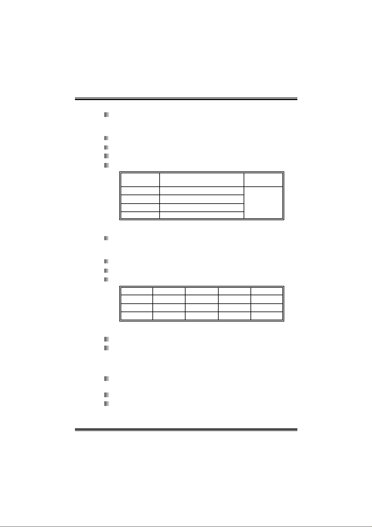
DI MM Socket
Location
DIMM1 128MB/256MB/512MB/1GB *1
DIMM2 128MB/256MB/512MB/1GB *1
DIMM3 128MB/256MB/512MB/1GB *1
DIMM4 128MB/256MB/512MB/1GB *1
DDR Module
To t al Me m o r y
Size (MB)
Max is 4 GB.
DDR Installa tion Notice:
Please f ollow the table below to install your DDR me mory
mo du le, or t he s y stem may not boot up or may not function
properly.
“SS” re presen ts Sin gle Side DDR memory module.
“DS” re present s Double Side DDR mem ory mod ule.
Star sign “*” represents leave the DIMM socket empty.
DIMM1 SS/DS
DIMM2
DIMM3
DIMM4
* * *
*
* * *
*
SS/DS SS/DS SS/DS
SS/DS SS/DS
SS/DS
SS/DS
On- boa rd IDE
2 on-board connectors support 4 IDE disk drives.
Supports PIO m ode 5, Bl ock Mode and Ultra DMA
33/ 66/100/ 1 33 bus mas t er mo de.
Serial ATA
4 on-board Serial ATA connectors support 4 serial ATA (SATA)
ports.
Compliant with SATA2.0 specific ation.
Data tra n sfer rates u p to 3Gb/s.
2
Page 5

NF4 Ul tra-A 9
Slots
Three 32bit PCI bus master slots.
Two PCI-Express x1 slots:
- PCI Express 1.0a com pli ant.
- Bandwidth 250MB/s per directio n.
One PCI-Express x16 slot.
- PCI Express 1.0a com pli ant.
- Maximum theoreti cal realized bandwidth of 4GB/s
s imu lta ne ously per d irection, for an ag gr egate of 8GB /s
totally.
One Xtreme Graphics Port slot. (See p.12 for detail information)
Super I/O
Chip: ITE IT 8712F.
Low Pi n Count Interface.
Provides the most commonly used legacy Super I/O
functionality.
Environment Control initiatives,
- H/W Monitor
- Fan Speed Controller
- IT E's "S mart Guardian" fun ction
On -b o ard A C’ 97 Audio So und Codec
Chip: ALC850:
¾ Compliant wi th AC’97 versi on2.3 specification.
¾ Supports 8 channels audio output
Chip: ALC655 (optional):
¾ Compliant wi th AC’97 versi on2.3 specification.
¾ Supports 6 channels audio output.
IEEE 1394A Chip (optional)
Chip: VIA VT 6307.
Supports 2 ports with tra n sfer up to 400Mb/s.
3
Page 6

NF4 Ul tra-A 9
Giga bit Ethernet LAN
NVIDIA Gigabit MAC + VITESSE Gigabit PHY VSC8201.
Supports 10 Mb/s, 100 Mb/s and 1Gb/s auto-negotiation.
Half/Full duplex capabi lit y.
Supports personal Firewall setup.
Suppo r ts ACPI power m anagem en t.
Supports NVIDIA StreamThru te chnology
- Isochronous controller pai red wi th Hyper T ransport results
in fas t es t networking perf ormanc e
Secur ity
NVIDIA Networking Processo r.
NVIDIA Fi rewall technology
- Native firewall solution, protects the PC from intruders by
fil tering unauthorized traffic.
Advanced features
- Remote access, configuration, monitoring
- Com man d l in e int er f ace (C LI)
- WMI scripts.
NVIDIA Active Armor
- Enhance network security, and providing users an
environment with both fast and secure.
Storage
NVIDIA RAID Technology
- RAID 0 disk striping for highest system and application
performance
- RAID 1 disk m i rroring support for fault tolerance
Support for both SATA and ATA-133 disk controller
standards
- RAID 0+1 disk striping and mirroring for highest
performance with fault tolerance
4
Page 7
NF4 Ul tra-A 9
Inter nal On-board Connectors and Headers
1 audio-out header supports audio-out facili ties.
1 front panel header supports front panel facilities.
1 CD-in connector supports CD-ROM audi o-in function.
1 SPDIF-out connector supports digital audio-out function.
1 SPDIF-in connector supports digital audio-in function
(optional ).
1 IEEE1394 header supports 1 1394 Fi rewire port (optional).
1 floppy connector supports 2 FDD devices with 360K, 720K,
1.2 M, 1.44M a nd 2.8 8M by tes.
2 IDE connectors support 4 IDE disk drives.
3 USB headers support 6 USB 2.0 ports at front panel.
4 Serial ATA connectors support 4 SATA devi ces.
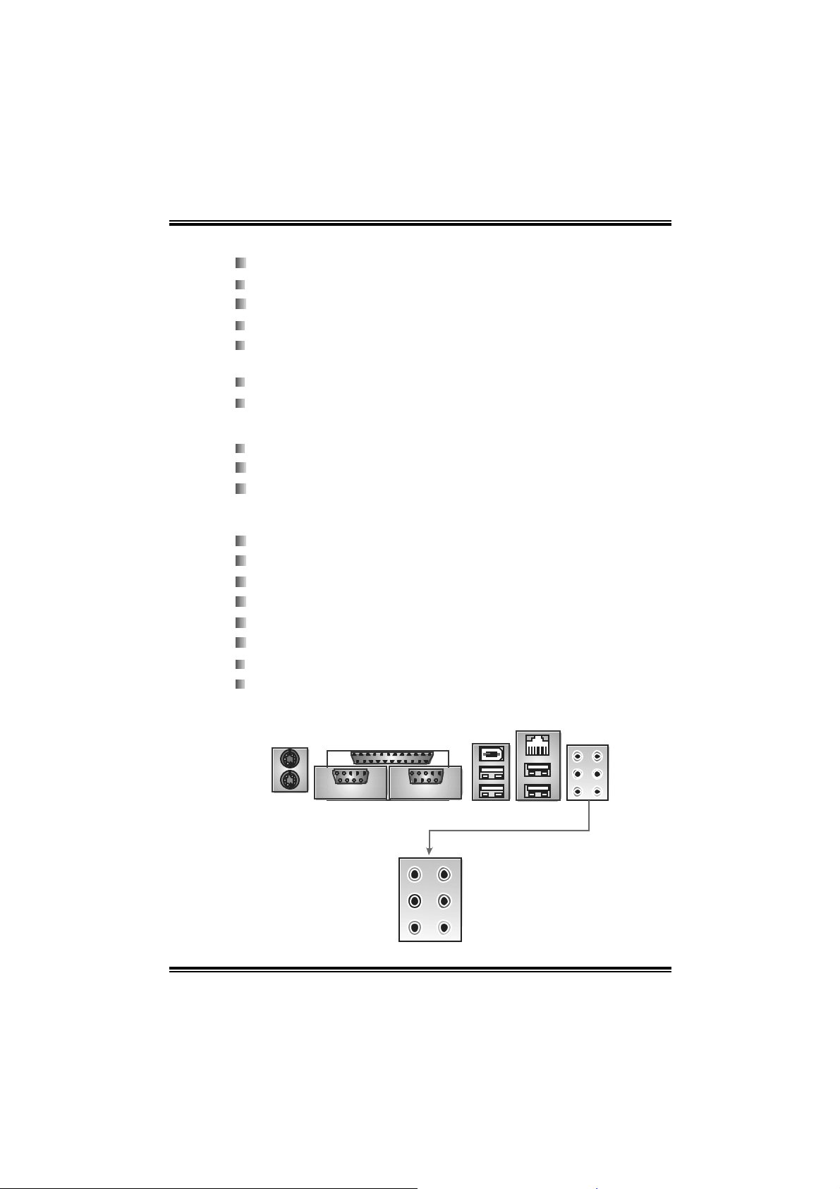
Rear (Back Pane l ) Side Connectors
1 PS/2 Mouse Port.
1 PS/2 Keyboa rd Port.
1 Printer Port.
1 Serial Port. (COM2 is optional.)
1 1394 Firewi re Port (optional).
1 RJ - 45 LAN jack.
4 USB 2.0 Ports.
6 audio ports support 8 channels audio-out faciliti es (wi th
ALC850).
LAN
PS/2
Mouse
Printer Port
1394 Port
(optional)
Connector
PS/2
Keyboard
COM1 COM2
Center/Left
( opti onal)
Rear
Si de
5
USB *2
Line-in
Line-out
MIC-i n
US B * 2
Page 8
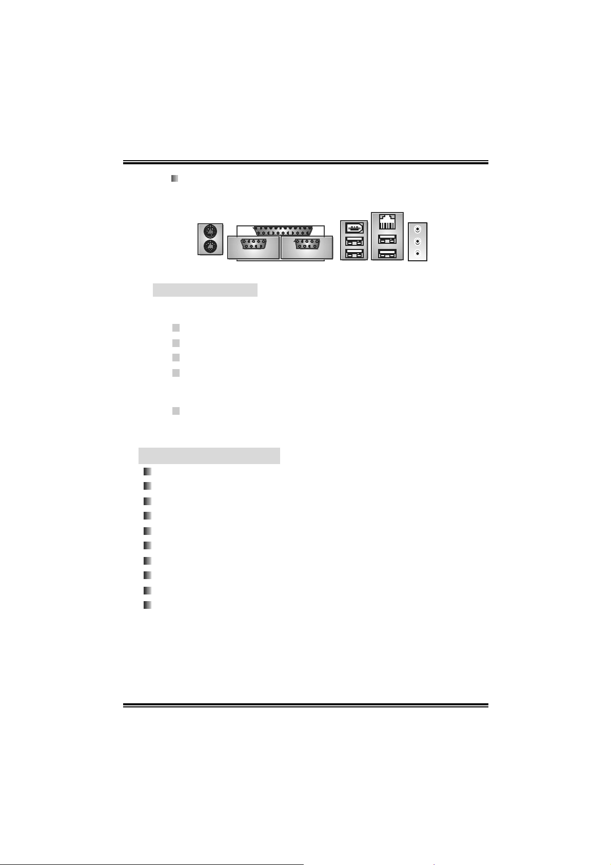
3 audio ports support 6 channels audio-out faciliti es (wi th
N
ALC 65 5, optiona l) .
PS/2
Mouse
PS/2
Key boar d
B. BIOS & Software
BIOS
Award legal BIOS.
Supports APM1.2.
Supports ACPI.
Supp orts USB Function.
Bundled Softwa re
Supports 9th Touch™, WINFLASHER™ and FLASHER™.
NF4 Ul tra-A 9
Printer Port
COM1 COM2
( optional)
1394 Port
(optional)
U SB * 2
LA
Connector
US B * 2
Line-in/R ear
Line-out
MIC-in/
Center/
Left
1.2 PACKAGE CHECKLIST
FDD Cable x 1
HDD Cable x 1
User’s Manu al x 1
Serial ATA Cable x 1
Fu lly Setup Driver CD x 1
Rear I/O P anel for ATX Case x 1
S/PDIF Cable x 1 (optional)
USB 2.0 Cable x 1 (opti onal)
IEEE 1394 Cable x 1 (optional)
Serial ATA Power Swi tch Cable x 1 (optional)
6
Page 9
NF4 Ul tra-A 9
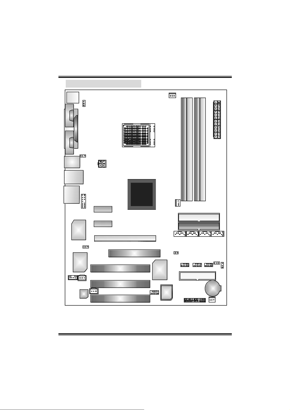
1.3 LA YOUT & COMPONENTS
JKB MS1
JCOM1
JCOM2
(op tional)
J1394_USB1
JUSB LA N1
EA RPHONEJACK1
C
O
M
1
C
O
M
2
Giga LA N
JKBM SV1
JPRNT1
J1394_USBV1
JATXPWR2
JAUDI O2
PCI- EX x1
PEX1- 2
PCI- EX x1
PEX1- 1
J1394PWR1
(opt ional)
XGP 1
IE EE 13 9 4
Chip
(optional)
JC DIN1
PCI1
JS PDIF_OUT
PCI2
Codec
JSPDIF_IN 1
PCI3
Note: ■ represents the 1st pin.
CPU1
PCI-EX16
nForce4
CK8-04
Ultra
Socket 939
Super I/O
J1394 A1
(optional)
JCFAN1
DIMM2
DIMM4
JNBF AN1
JSATA1 JSATA2 JSATA 3 JSATA4
JCI1
BIOS
JPANEL1
IDE2
IDE1
FDD1
JATXPWR1
DI MM 1
DIMM3
JUSBV1
JUSB3JUSB2JUSB1
JCMOS1
BAT1
JSFAN1
7
Page 10
NF4 Ul tra-A 9
CHAPTER 2: HARDW ARE INSTALLATION
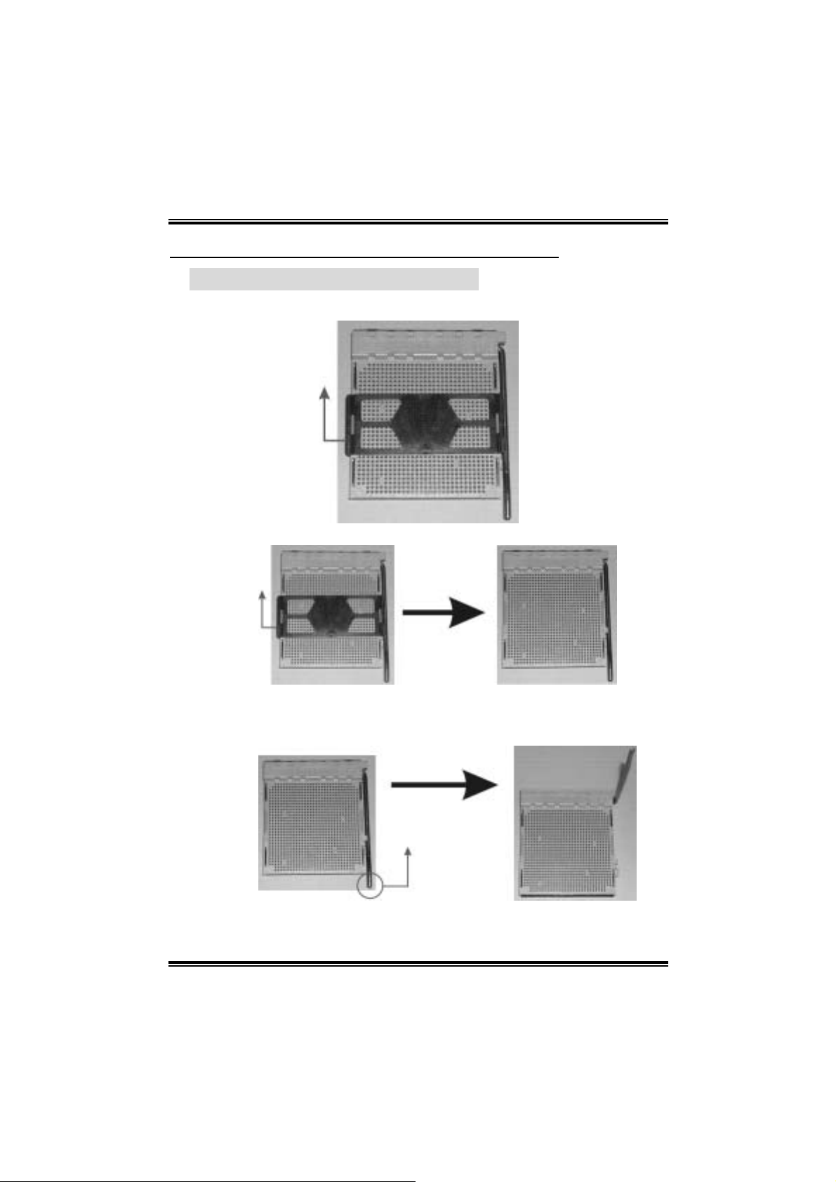
2.1 CENTRAL PROCESSING UNIT (CPU)
Step 1: Remove the socket protection cap.
Step 2: Pull the lever sideways away from the socket and then raise the
lever up to a 90-degree angle.
8
Page 11
NF4 Ul tra-A 9
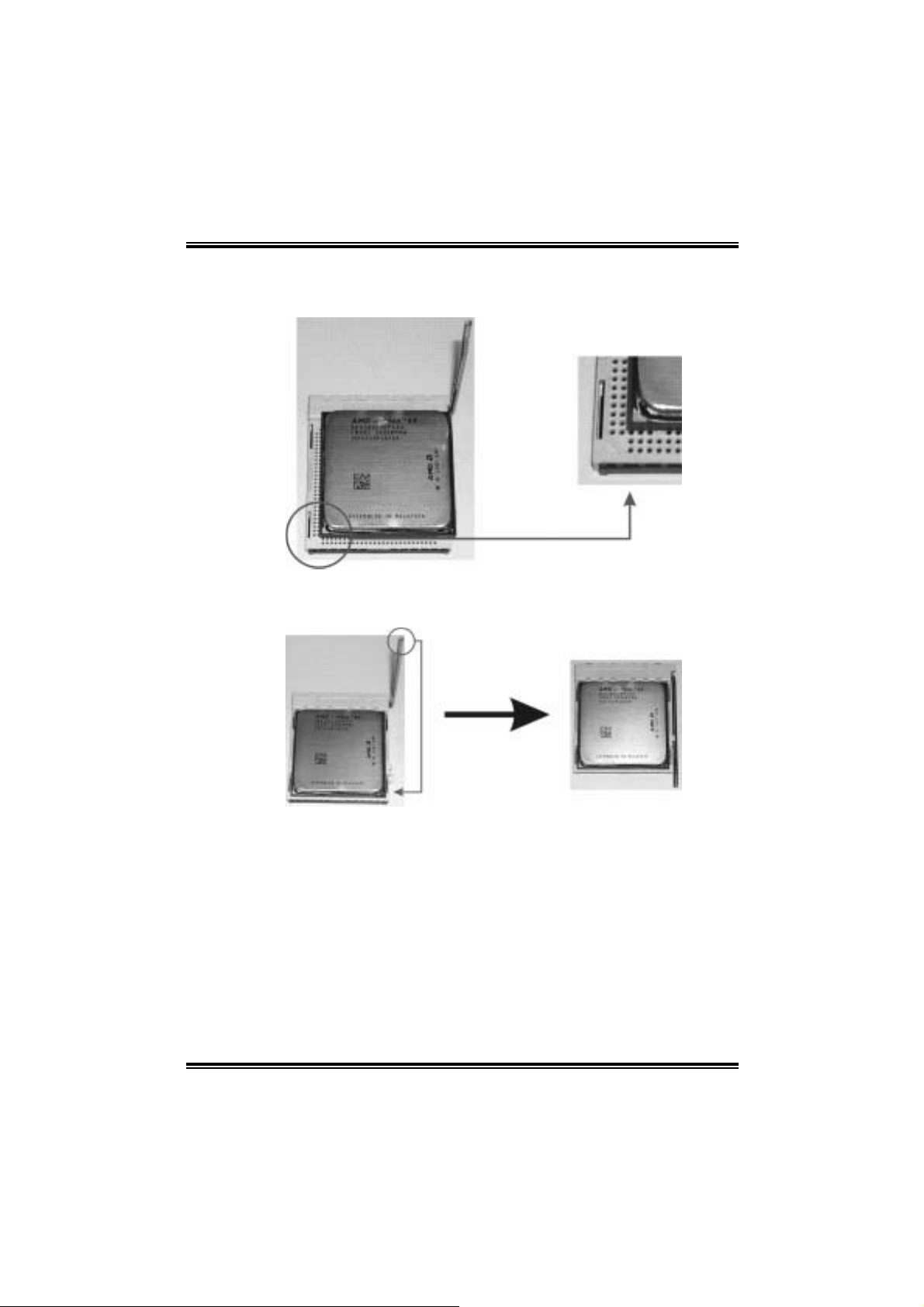
Step 3: Look for the bl ack cut edge on socket, and the white dot on CPU
should point forwards thi s black cut edge. The CPU will fit only in
the correct orientation.
Step 4: Hol d the CPU down firmly, and then close the lever to complete
the i nstalla ti on.
Step 5: Put the CPU Fan on the CPU and buckle it. Connect the CPU FAN
power cabl e to the JCFAN1. Thi s compl etes the i nstallation.
9
Page 12
NF4 Ul tra-A 9
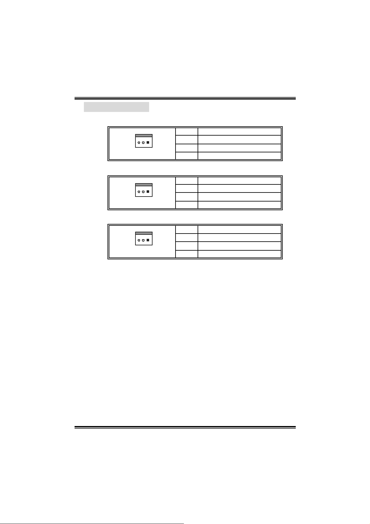
2.2 FAN HEADERS
CPU FAN Po wer Header: JCFAN1
Pin Assignment
1 Ground
13
System Fan Power Header: JSFAN1
13
North Bri dge Fan Power Hea der: JNBFAN1
13
Note:
The JCF AN1, JSF AN 1and JN BF AN1 s upport system cooling fan with
Smart Fan C ont rol utility. It support s 3 pin head c onnector. When
connec t ing wit h wires onto c onnectors, please not e that t he red wire is the
posit iv e and should be connec t ed to pin#2, and t he blac k wire is Ground
and should be connec t ed to GND.
2 +12V
3 FAN RPM rate sense
Pin Assignment
1 Ground
2 +12V
3 FAN RPM rate sense
Pin Assignment
1 Ground
2 +12V
3 FAN RPM rate sense
10
Page 13
NF4 Ul tra-A 9
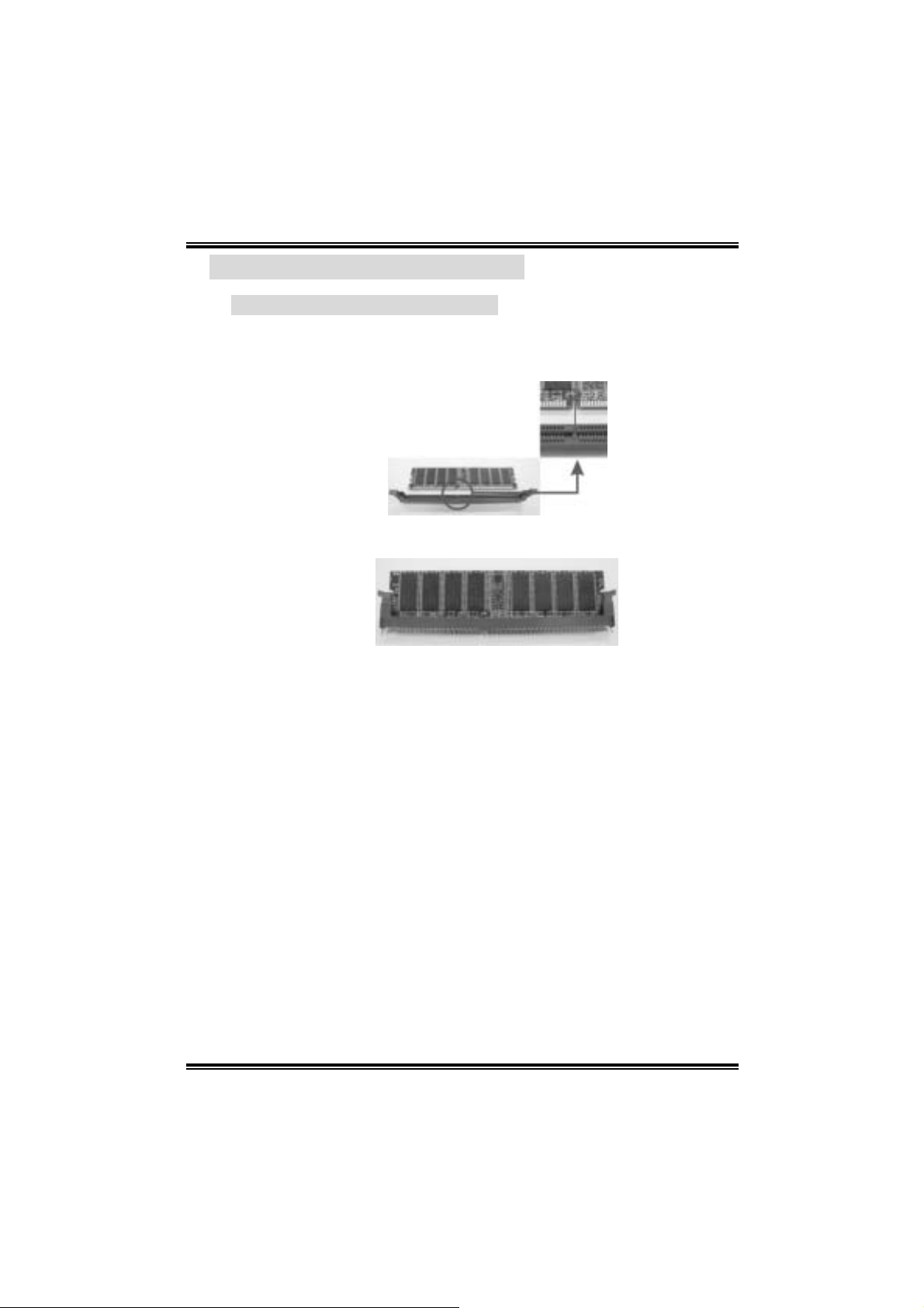
2.3 MEMORY MODULES INSTAL LAT ION
2.2.1 DDR M o dule ins tallat ion
1. Unlock a DIMM sl ot by pressi ng the retaining clips outward. Align a
DIM M on the sl ot such that the notch on the DIMM matches the break
on the Slot.
2. Insert the DIMM verticall y and firm ly into the slot until th e retaining chip
snap back in place and the DIMM is properly seated.
11
Page 14

NF4 Ul tra-A 9
2.4 CONNECTO RS, & SLOTS
Floppy Disk Connector: FDD1
The m otherboard provides a standard fl oppy disk connector that
s uppor t s 360 K, 720K, 1.2 M, 1.4 4M and 2. 8 8 M f lo ppy d is k types. Th is
connector supports the provided floppy drive ribbon cabl es.
Hard Disk Connectors: IDE1/IDE2
The m otherboard has a 32-bit Enhanced PCI IDE Control ler that
provides PIO Mode 0~5, Bus Master, and Ul tra DMA 33/66/100/133
functionality. I t has two HDD conn ecto rs IDE1 (primary) an d IDE2
(secondary).
The IDE connectors can connect a master and a slave drive, so you can
connect up to four hard disk dri ves. The fi rst hard drive should always be
connected to IDE1.
Peripheral Component Interconnect Slots: PCI1~PCI3
This m otherboard is equipped with 3 standard PCI slot. PCI stands for
Peripheral Component Interconnect, and it is a bus standard for
expansion cards. T his PCI sl ot is designated as 32 bits.
Xtreme Graphics Port Slot: XGP1
This XGP (Xtreme Graphics Port) slot is a special design that onl y
supports compatible AGP VGA cards.
To install the system with an add-on AGP VGA card, please make sure
to install the driver of add-on AGP VGA card before onboard VGA driver
instal lation. If the onboard VGA driver has al ready been installed before
you install the add-on AGP VGA card, the system wil l autom atically set
the onboard VGA as the primary graphics adapter.
For the onboard VGA driver can’t be removed completel y, and to solve
this problem, please follow the steps bel ow,
1. Disable onboard VGA utility under the operating system, and reboot
PC. After PC restarts, the system will automatically set the AGP
VGA card as the graphi cs adapter.
2. Re-instal l your operati ng system to ensure the AGP VGA card
function c an be us ed.
Note:
Please go to “http: // www.biostar. c om.tw” for more detailed inform ation
about XGP compatibl e AGP cards.
12
Page 15
NF4 Ul tra-A 9
CHAPTER 3: HEADERS & JUMPERS SETUP
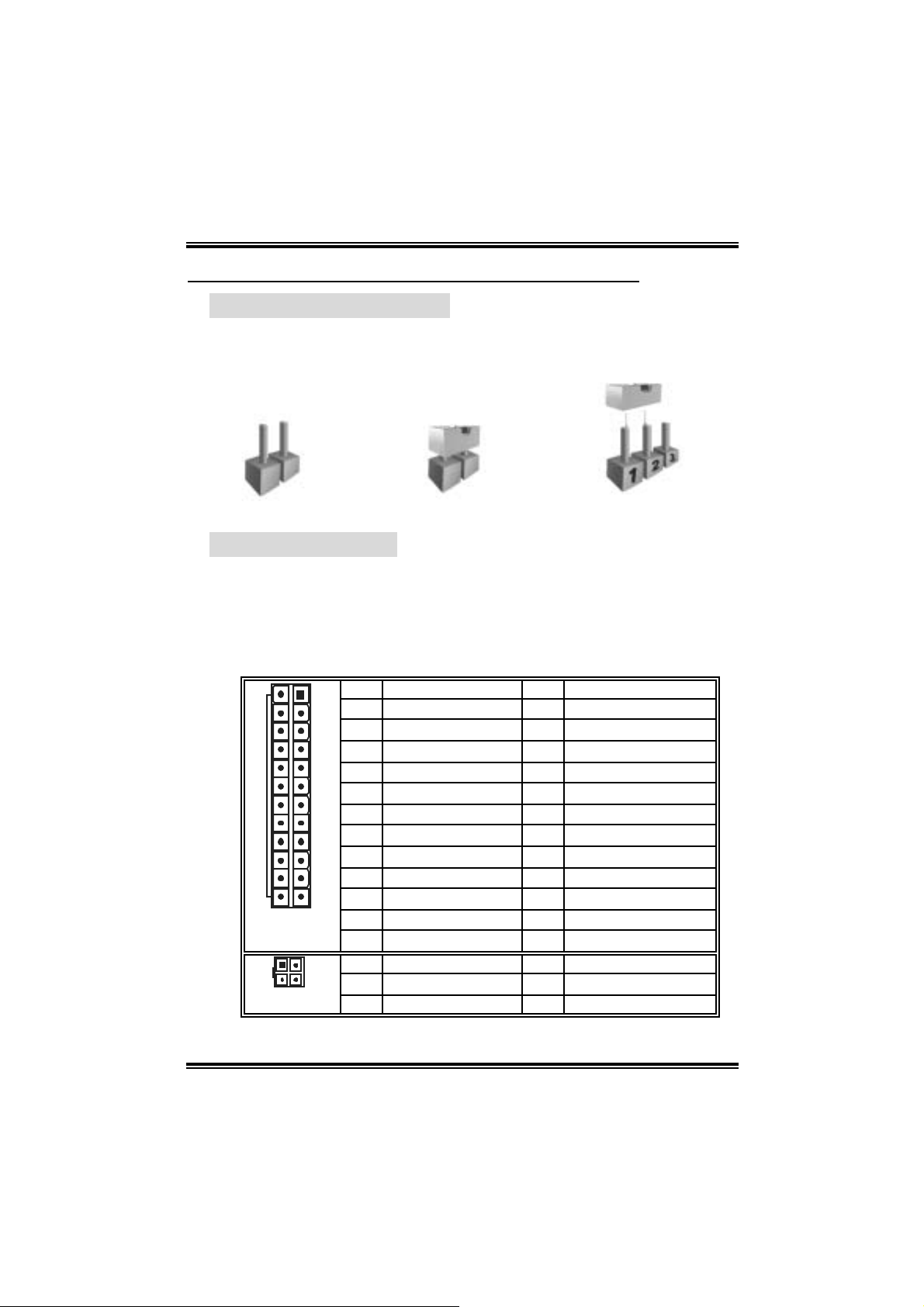
3.1 HOW TO S ETUP JUMPE RS
The illustration shows how to set up jumpers. When the jumper cap i s
placed on pins, the jumper i s “close”, if not, that means the jumper is
“open”.
Pin opened Pin closed Pin1-2 closed
3.2 DETAIL SETTINGS
ATX Power So urc e Connectors: JATX PWR1/ JATX PWR2
JATXPWR1: This connector allows user to connect 20-pin power
conn ec tor on t h e A TX power s upply.
JATXPWR2: By connecting this connector, it will pro vi de +12 V to CPU
power circuit.
13
24
JATXPWR1
JATXPWR2
1
12
1
4
23
Pin Assignment Pin Assignment
1 +3.3V 13 +3.3V
2 +3.3V 14 -12V
3 Ground 15 Ground
4 +5V 16 PS_ON
5 Ground 17 Ground
6 +5V 18 Ground
7 Ground 19 Ground
8 PW_OK 20 -5V
9 Standby Voltage +5V 21 +5V
10 +12V 22 +5V
11 +12V 23 +5V
12 Detect 24 Ground
Pin Assignment Pin Assignment
1 +12V 3 Ground
2 +12V 4 Ground
13
Page 16
NF4 Ul tra-A 9
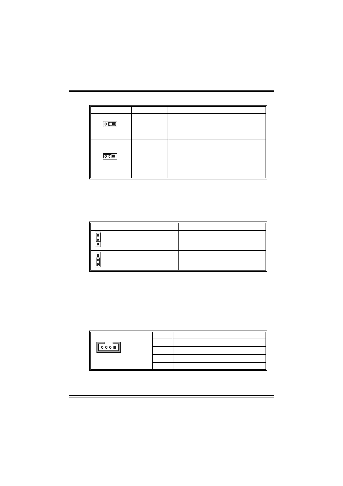
Power Source He ade rs for USB Ports: J1394_USBV1/JUSBV1
Assignment Description
3
1
Pin 1-2 clo se
Pin 2-3 clo se
3
1
+5V
+5V st andby
Voltage
J1394_U SBV1: +5V f or U SB ports at
J1394_U SB1 and JU SBLAN 1.
JU SBV1: +5V f or f ront USB headers
(JUSB1/JUSB2/JUSB3).
J1394_U SBV1: USB ports at
J1394_U SB1 and JU SBLAN 1 are
powered wit h +5V standby v oltage.
JU SBV1: Front U SB headers
(JU SB1/JU SB2/JUSB3) are powered
with +5V standby volt age.
Note:
In order to support this function “Power-on system via USB devi ce,”
“J1394_USBV1/JUSBV1” jumper cap should be placed on Pi n 2-3
individually.
Power Source Header for PS /2 Keyboard/Mouse: JKBMSV1
Assignment Description
1
3
Pin 1-2 close
1
3
Pin 2-3 close
Note:
In order to support this function “Power-on system via keyboard and
mouse”, “JKBMSV1” j umper cap shoul d be placed on Pin 2-3.
+5V +5V for ke yboard and mouse
+5V Standby
Voltage
PS/2 k eyboard and m ouse are
powered wit h +5V standby v oltage.
CD-ROM Audi o-in Conne c tor: JCDIN1
This connector allows user to connect the audio source from the variety
devi c es, like CD-RO M, DVD-ROM, P CI sound card , PCI TV turn er card
etc..
Pin Assignment
1 Lef t channel input
2 Ground
14
JCDIN1
3 Ground
4 Right channel input
14
Page 17
NF4 Ul tra-A 9
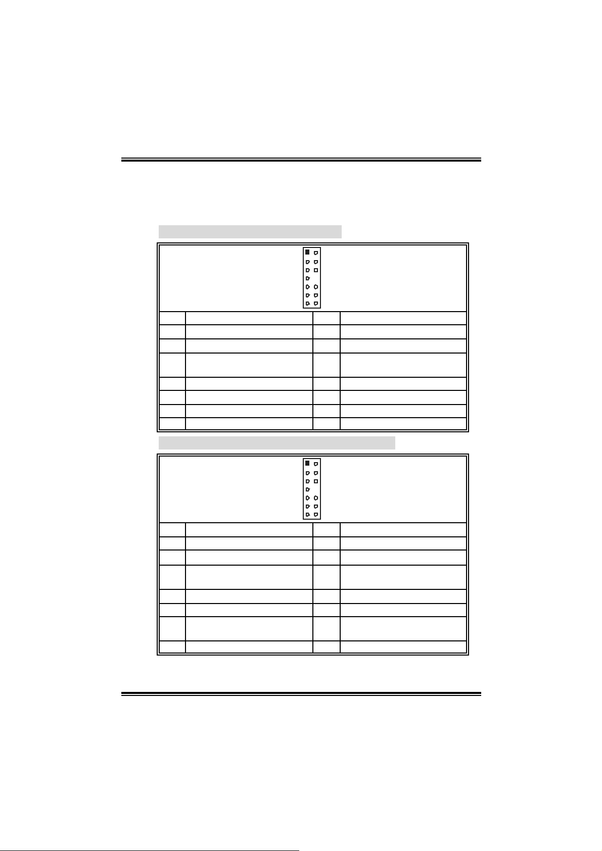
Fr o nt P anel Audio-out Header : JAUDIO2
This conn ec tor will allow user to con ne c t wit h the fron t audio out p ut
heade rs on the P C c ase. It will disable the output on back pan el audio
connectors.
With ALC850 Audio Sound Codec:
12
13 14
Pin Assignment Pin Assignment
1 Mic in/Stereo MIC -in R. 2 Ground
3 Stereo MIC-in L. 4 Audio power
Right line out/ Speaker out
5
Right
7 Reserved 8 Key
9 Lef t line out/Speaker out Lef t 10 Left line out/Speaker out Lef t
11 R ight line in 12 Right line in
13 Left line in 14 Left line in
Right line out/ Speaker out
6
Right
With ALC655 Audio Sound Codec (optional):
12
13 14
Pin Assignment Pin Assignment
1 Stereo MIC-in R / Center 2 Ground
3
Stereo M IC-in L/ Bass
Right line out/ Speaker-out
5
Right
7 Reserved 8 Key
9 Lef t line out/Speaker-out Lef t 10 Lef t line out /Speaker out Left
Right line in/R ear speaker
11
Right
13 Left line in/R ear speak er Left 14 Left line in/ R ear speak er Left
4 Audio power
Right line out/ Speaker-out
6
Right
Right line in/R ear speaker
12
Right
15
Page 18
NF4 Ul tra-A 9
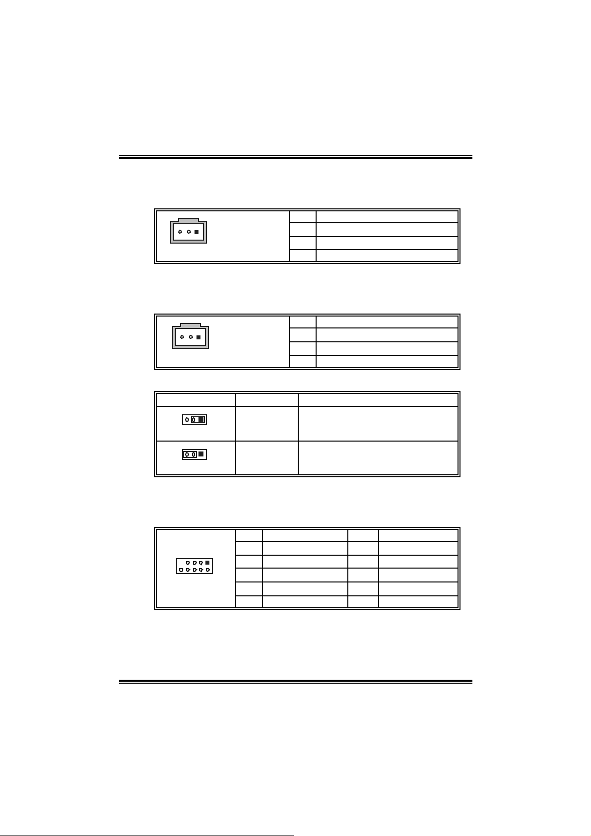
Digital Audio-out Connector: JSPDIF_OUT
This conn ec tor will allow user to con ne c t the PCI brac ket S PDI F ou tput
header.
Pin Assignment
1 +5V
13
JSPDIF_OUT
2 SPDIF OUT
3 Ground
Digita l Aud io-i n Connector: JSPDIF _IN1 ( optiona l)
This conn ec tor will allow user to con ne c t the PCI brac ket S PDI F ou tput
header.
Pin Assignment
1 +5V
13
JSPDIF_IN1
2 SPDIF In
3 Ground
Power Source Header fo r 1394 Chip: J1 39 4PWR 1 ( option a l)
Assignment Description
3
1
Pin 1-2 clo se
3
1
Pin 2-3 clo se
+3.3V
+3.3V SB +3.3V SB f or 1394 chips et.
+3.3V for 1394 chipse t.
(Default)
Header for 1394 Firewire Port at Front Panel: J1394A1 (option al)
This connector allows user to connect the front 1394 port for digital
image devi ces.
Pin Assignment Pin Assignment
1
210
1 A+ 2 A3 Ground 4 Ground
5 B+ 6 B7 +12v 8 +12V
9 Key 10 Ground
16
Page 19
NF4 Ul tra-A 9
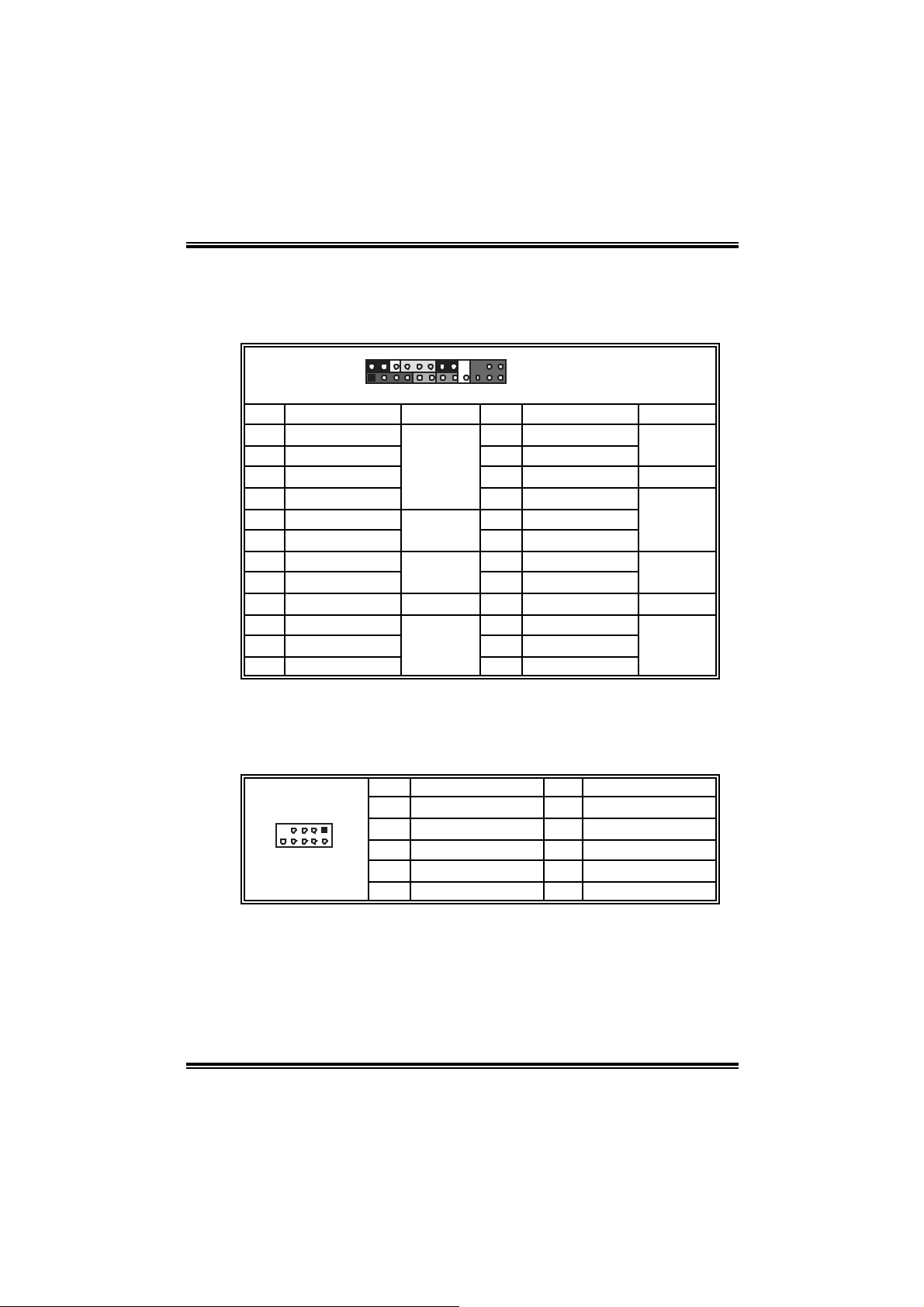
Header for Fr ont Pan el Faci lities: J PA NEL1
This 24-pin connector includes Power-on, Reset, HDD LED, Power LED,
Sleep button, speaker and IrDA Connection. It allows user to connect
the PC case’s front panel switch functi ons.
2
24
1
23
JPANEL1
Pin Assignment Function Pin Assignment Function
1 +5V 2 Sleep control
3 N/A 4 Ground
5 N/A 6 N/A N/A
7 Speaker
9 H DD LED (+) 10 Power LED (+)
11 HDD LED (-)
13 Ground 14 Power button
15 Reset control
Speaker
Connector
Hard drive
LED
Reset
button
8 Power LED (+)
12 Power LED (-)
16 Ground
Sleep
button
Power LED
Power-on
button
17 N/A 18 Key
19 N/A 20 Key
21 +5V 22 Ground
23 IRTX
IrDA
Connector
24 IRRX
IrDA
Connector
Headers for USB Ports at Front Panel: JUSB1~JUSB3
This connector allows user to connect additional USB cabl es at PC front
panel, and also can be connected with internal USB devices, like USB
card reader.
Pin Assignment Pin Assignment
1
210
1 +5V (f us ed) 2 +5V (fused)
3 USB- 4 USB5 USB+ 6 USB+
7 Ground 8 Ground
9 Key 10 NC
17
Page 20
NF4 Ul tra-A 9
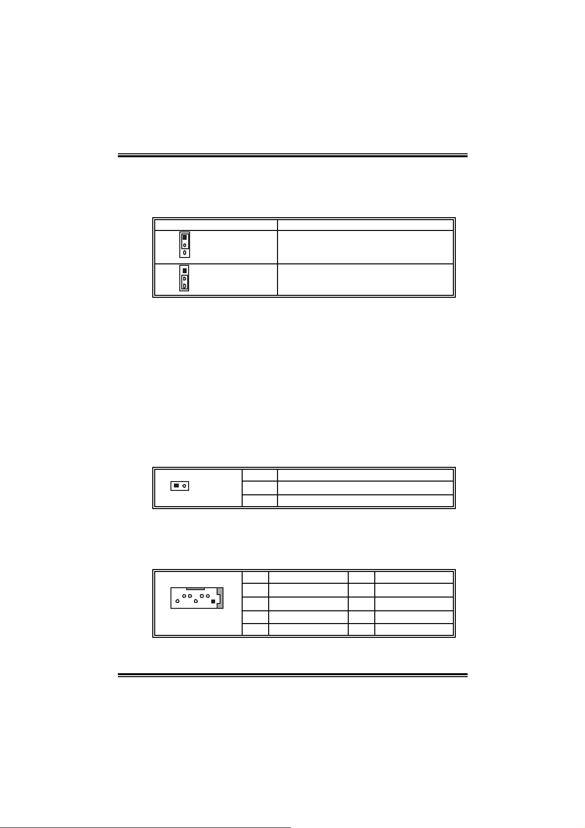
Close CMOS Header: JCMOS 1
By placing the jumper on pin2-3, it allows user to restore the BIOS safe
setting and the CMOS data, please careful l y follow the procedures to
avo id da ma ging th e mot her b oar d.
JCMOS1 Assignment
1
3
Pin 1-2 close
1
3
Pin 2-3 close
Norm al Operation (D ef ault).
Clear CMOS data.
※ Clear CMOS Procedures:
1. Remove AC power line.
2. Set the jumper to “Pin 2-3 close”.
3. Wait for f i ve seconds.
4. Set the jumper to “Pin 1-2 close”.
5. Power on the AC.
6. Reset your desired password or clear the CMOS data.
Case Op en Header: JCI 1
T his connector allo ws system to moni to r PC case open status. If the
signal has been triggered, i t will record to the CMOS and show the
message on next boot-up.
Pin Assignment
2
1
JCI1
1 Cas e open signal
2 Ground
Se rial ATA Connector: JSATA1~JS ATA4
The m otherboard has a SATA Controll er in nForce4 (CK8-04) with 4
channel s SATA interface, i t satisfies the SATA 1.0 spec and with transfer
rate of 1.5Gb/s.
Pin Assignment Pin Assignment
1 Ground 2 TX+
3 TX- 4 Ground
147
5 RX- 6 RX+
7 Ground
18
Page 21

NF4 Ul tra-A 9
;
s
CHAPTER 4: USEFUL HELP
4.1 AWARD BIOS BEEP CODE
Beep Sound Meanin g
One long beep f ollowed by t wo s hort
beeps
High-low siren sound CPU overheated
One Short beep when system boot-up No error found during POST
Long beeps every ot her sec ond No DRAM detected or inst all
4.2 TROUBL ESHOOTIN G
Probable Solution
1. N o power to the sy stem at all
Power light don’t illuminat e, fan
inside power supply does not t urn
on.
2. I ndic at or light on key board does
not t urn on.
Sys t em inoperat iv e. Key board lights
are on, power indic at or lights are lit,
and hard driv e is spinning.
Sys t em does not boot from hard dis k
drive, can be booted f rom optical driv e.
Sys t em only boots f rom opt ic al driv e.
Hard disk can be read and applic ations
can be used but booting f rom hard dis k
is imposs ible.
Screen m essage say s “Invalid
Conf igurat ion” or “CMOS Failure.”
Cannot boot sys t em af t er inst alling
sec ond hard drive.
Video card not f ound or v ideo card
mem ory bad
Sys t em will shut down autom at ically
1. Make s ure power c able is
sec urely plugged in.
2. Replace cable.
3. Contact techni cal support.
Us ing even pres s ure on bot h ends of
the DIMM, press down firm ly unt il the
module s naps int o place.
1. C hec k cable running f rom disk t o
disk controller board. Make sure
both ends are s ecurely plugged in
chec k the drive type in t he
standard CMOS setup.
2. Bac k ing up the hard drive is
ext rem ely im portant. All hard disk
are capable of break ing down at
any time.
Back up data and applications f iles.
Ref orm at t he hard driv e. R e-install
applicat ions and dat a using bac k up
disks.
Rev iew system’s equipm ent. Make
sure c orrect informat ion is in setup.
Set master/slave jumpers correctly.
Run SETUP program and s elect
correc t driv e types. Call t he drive
manuf acturers f or c ompatibility with
other driv es.
19
Page 22

NF4 Ul tra-A 9
CHAPTER 5: NVIDIA RAID FUNCTIONS
5.1 OPERATION SYSTEM
Wi ndows XP home Edition
Wi ndows XP Professional Edition
Wi ndows 2000 Professional
5.2 RAID ARRAYS
NVRAID supports the following types of RAID arrays:
RAID 0:
RAID 0 defi nes a disk striping schem e that improves disk read and writes
tim es for many applicati ons.
RAID 1:
RAID 1 defi nes techniques for mirroring data.
RAID 0+1:
RAID 0+1 com bines the techniques used i n RAID 0 and RAID 1.
Spanning (JBOD):
JBOD provides a method for combining drives of different sizes in to one
large di sk.
20
Page 23

NF4 Ul tra-A 9
5.3 HOW RAID WORKS
RAID 0:
Th e contro lle r “stripes” data acro ss mult iple driv e s in a RAID 0 array
sys te m. It breaks up a large fi le into small er blocks an d performs disk
reads and writ es across m ultiple drives in parallel. T he size o f each
block is determined by the strip size paramet er, which you set during
the creation of the RAID set based on the syst em environment.
This technique reduces overall disk access time and offers high
bandwidth.
nVIDIA
nFor ce 4
CK8-04
Ultra
Block 1
Block 3
Block 5
Block 2
Block 4
Block 6
Feat u r es and Benef its
¾ Drives: Minimum 1, and ma ximum i s up to 6 or 8. Depending on
the p lat f or m .
¾ Uses: Intended for non-critical data requiring high data
t hroughp ut, or any envi r onment that does n ot re quire fault
tolerance.
¾ Benefits: provides i ncreased data throughput, especially for
large files. No capacity loss penalty for parity.
¾ Drawbacks: Does not deliver any fault tol erance. If any drive i n
the array fail s, all da ta is lost.
¾ Fa ult Tole rance : No.
21
Page 24

NF4 Ul tra-A 9
RAID 1:
Every read and write is actually carried out in p ar allel across 2 disk
drives in a RAID 1 array system. Th e mirro r ed (backup) copy of the
dat a c an res ide on t he s ame dis k or on a second redundant dri ve i n the
array. R AID 1 prov ide s a hot-standby copy of data if th e ac tiv e volume
or drive is corrupted or becomes unav ailable because of a hardware
failure.
RA ID technique s can be applied for h igh-avai labi l ity s olut ions , or as a
form of auto matic backup that elimin ates tedious m anual backups t o
mo r e expensive and less reliable media.
nVIDIA
nFor ce 4
CK8-04
Ultra
Block 1
Block 2
Block 3
Block 1
Block 2
Block 3
Feat u r es and Benef its
¾ Drives: Minimum 2 , a n d m ax i mum is 2.
¾ Uses: RAID 1 is i deal for sm all databases or any other
app l ica ti on t h at req u ir es fau lt t o lerance an d minimal ca pacity .
¾ Benefits: Provides 100% data redundancy. Should one drive
fail , the controller switches to the other drive.
¾ Drawbacks: Requi res 2 drives for the storage space of one
drive. Performance is impaired during drive rebuilds.
¾ Fa ult Tole rance : Yes.
22
Page 25

NF4 Ul tra-A 9
RAID 0+1:
RA ID 0 drives can be mi rrored s uing R AID 1 t echnique s . R esulting in a
RAID 0 +1 solut ion for improved p erform ance plus resiliency.
nVIDIA
nForce 4
CK8-0 4
Ult ra
Block 1
Block 3
Block 5
Block 2
Block 4
Block 6
Block 1
Block 3
Block 5
Block 2
Block 4
Block 6
Feat u r es and Benef its
¾ Drives: Minimum 4, and maximum is 6 or 8, depending on the
platform .
¾ Benefits: Optimizes for both fault tolera n ce and performance,
allowing for automatic redundancy. May be simultaneously used
with other RAID levels in an array, and allows for spare di sks.
¾ Drawbacks: Requi res twice the avai lable disk space for data
redundancy, the same as RAID l evel 1.
¾ Fa ult Tole rance : Yes.
23
Page 26

NF4 Ul tra-A 9
S p anning (JBOD):
JBOD st ands f or “Just a Bunch of Disks”. Each drive is accessed as if it
were on a standard SCSI h ost bus adapter . Th is is useful when a single
dr ive configuration is neede d, but it offers no speed improv ement or
fault tolera nce.
nVIDIA
nForce 4
CK8-04
Ultra
Single Logi cal
Drive
Disk 1: 40GB
Disk 2: 80GB
Disk 3: 40GB
Disk 4: 120GB
Feat u r es and Benef its
¾ Uses: JBOD works best if you have odd sized drives and you
want to combine them to m ake one big drive.
¾ Benefits: JBOD provides the ability to combine odd si ze drives
us ing a ll of th e ca pacity of t he drives.
¾ Drawbacks: Decreases performance because of the difficul ty in
us ing dr iv es concur r ently .
¾ Fa ult Tole rance : Yes.
※ For more det ailed setup informa tion, ple ase re fer to the Dri ver CD, or
go to
h ttp://www.nv idia.com/page/pg_20011106217193.html to download
NVIDI A nF o rce T u to ri al Flash .
24
Page 27

NF4 Ul tra-A 9
CHAPTER 6: W ARPSPEEDER™
6.1 INTRO DUCTION
[WarpSpeeder™], a new powerful control utility, features three
user-friendly functions includi ng Overclock Manager, Overvoltage
Manager, and Hardware Monitor.
Wi th the Overcl ock Manager, users can easi ly adjust the frequency they
prefer or they can get the best CPU performance with just one click. The
Overvoltage Manager, on the other hand, hel ps to power up CPU core
vol tage and Me mor y v ol ta ge. Th e co o l H ardw are Mo ni tor s mar tly in d icates
the temperatures, vol tage and CPU fan speed as well as the chipset
information. Al so, in the About panel, you can get detail descriptions about
BIOS m odel and chipsets. In additi on, the frequency status of CPU,
mem ory, AGP and PCI along with the CPU speed are synchronically
s how n on our ma i n p an el .
Moreover, to protect users' computer systems i f the setting is not
appropriate when testing and results i n system fail or hang,
[WarpSpeeder™] technology assures the system stability by automatically
rebooting the computer and then restart to a speed that i s either the
original system speed or a suitable one.
6.2 SYSTEM REQUIREMENT
OS Support: Windows 98 SE, Windows M e, Windows 2000, Windows XP
DirectX: DirectX 8.1 or above. (T he Windows XP operating system
includes DirectX 8.1. If you use Wi ndows XP, you do not need to instal l
Dir ec tX 8.1.)
25
Page 28

NF4 Ul tra-A 9
6.3 INSTALL ATION
1. Execute the setup executi on file, and then the following dialog will pop
up. Please click “Next” button and foll ow the default procedure to
install.
2. When you see the following dialog in setup procedure, i t means setup
is completed. If the “Launch the WarpSpeeder Tray Utility” checkbox
is checked, th e Tray Ico n utili ty an d [WarpSpe ed er™ ] utilit y will b e
automati cally and imm ediatel y launched after you click “Finish”
button.
Usage:
The following figures are j ust only for reference, the screen printed in
this user manual will chan ge a c c ordin g to your motherboard on hand.
26
Page 29

NF4 Ul tra-A 9
6.4 [WARPSPEEDER™] INCLUDES 1 TRAY IC ON AND 5 PAN ELS
1. Tray Icon:
Whenever the T ray Icon utility is launched, it will displa y a little t ray
icon on the right si de of Windows Taskbar.
This utility is responsi ble for conveniently i nvoking [WarpSpeeder™]
Utility. You can use the mouse by clicking the left button in order to
invoke [WarpSpeeder™] directly from the little tray icon or you can
right-click the little tray icon to pop up a popup menu as followi ng
figure. T he “Launch Utility” item in the popup menu has the same
function as mouse left-click on tray ic on and “Exi t” item will close
T ray Icon utility if se lected.
27
Page 30

NF4 Ul tra-A 9
2. Main Panel
If y ou click the tra y icon, [Wa rpSpeeder™] utilit y will be invoked.
Please refer to the following fi gure; the utility’s first window you will
see is Main Panel.
Main Panel contains features as foll ows:
a. Display the CPU Speed, CPU external clock, Memory clock,
AGP clock, and PCI cl ock information.
b. Contains About, Voltage, Overclock, and Hardware Monitor
Buttons for invoking respective panel s.
c. With a us er - fr ie nd ly Status Animatio n, it c an r epr esent 3
overclock percentage stages:
Man walking→overcl ock percentage from 100% ~ 110 %
Panther running→overclock percentage from 110% ~ 120%
Ca r racing→overclock percentage from 120% ~ above
28
Page 31

NF4 Ul tra-A 9
3. Vol ta ge Panel
Clic k the Vol tage button in Main Pa nel , the button will be highligh te d
and t he Vol ta ge Pa ne l will slide out t o up as the f ollowing fig ure.
In this panel , you can decide to increase CPU core voltage and
Memory vo ltage or not. The default settin g is “No”. If you want to ge t
the best performance of overcl ocking, we recommend you click the
option “Yes”.
29
Page 32

NF4 Ul tra-A 9
4. Over clock Pa nel
Clic k the Overcloc k button in Ma in Pa ne l, the button will be
highlighted and the Overcl ock Panel will slide out to left as the
fol l owi ng f igur e.
Overclock Panel contains the these features:
a. “–3MHz button”, “-1MHz button”, “+1M Hz button”, and “+3M Hz
button”: provide user the ability to do real-time overclock
adj ustment.
Warning:
Manually overclock is pot entially dangerous, especially when t he
overc locking percentage is over 110 %. We s t rongly rec ommend you
verif y ev ery s peed you ov erc lock by c lick the Verify butt on. Or, you c an
just click Aut o ov erclock but t on and let [W arpSpeeder™] aut om atically
gets the best result f or y ou.
b. “Recovery Dialog button”: Pop up the followi ng dialog. Let user
select a restori ng way if system need to do a fail-safe reboot.
30
Page 33

NF4 Ul tra-A 9
c. “Auto-overclock button”: User can click this button and
[Wa rpS pee der™] will set th e be st and sta ble perf ormance and
frequency automatically. [WarpSpeeder™] utility will execute a
series of testing un til syst em fail . Then system will do fail-saf e
reboot by using Watchdog function. After reboot, the
[WarpSpeeder™] utility will restore to the hardware default
setting or load the veri fied best and stable frequency according
to th e Reco very Dialog’s setting.
d. “Verify button”: User can click this button and [WarpSpeeder™]
will proceed a testing for current frequency. If the testing is ok,
then the curre n t freq uency will be sa ved in to syste m regi stry. If
the testing fail, system will do a fail-safe rebooting. After reboot,
the [WarpSpeede r™ ] utility will resto re to the ha rdware default
setting or load the veri fied best and stable frequency according
to th e Reco very Dialog’s setting.
Note:
Becaus e the t esting programs, inv ok ed in Aut o-overclock and Verify,
include D irectDraw, D irect3D and D irectShow t ests, the Direc t X 8.1 or
newer runtime library is required. And please m ak e s ure your dis play
card’s color depth is High color (16 bit) or True c olor( 24/ 32 bit ) t hat is
required for Direct3D rendering.
5. Hardware Monitor Panel
Clic k the Hardware Monitor butt on in Main Pa ne l, the bu tton will be
highlighted and the Hardware Monitor panel will slide out to left as
the fo l lowing f ig ur e.
In this panel , you can get the real-time status information of your
system. The informati on will be ref reshed every 1 second.
31
Page 34

NF4 Ul tra-A 9
6. About Panel
Click the “about” button i n Main Panel, the button will be highlighted
and th e About Pa nel w il l s lid e out to up as the follow in g f igur e.
In this panel, you can get model name and detail inform ation i n hints
of all the chi pset that are related to overclocking. You can also get
the mainboard’s BIOS model and the Version number of
[WarpSpeeder™] utility.
32
Page 35

NF4 Ul tra-A 9
Note :
Because the overcl ock, overvol tage, and hardware monitor features
are controlled by several separate chipset, [WarpSpeeder™] divide
these features to separate panels. If one chi pset is not on board, the
correlative button in Main panel will be disabled, but will not i nte r fere
other panels’ functions. T his property can make [WarpSpeeder™]
utility more robust.
08/15, 2005
33
Page 36

NF4 Ultra-A9 BIOS Setup
BIOS Setup........................................................................................1
1 Main Menu.......................................................................................................3
2 Standard CMOS Features...................................................................................6
3 Advanced BIOS Features...................................................................................9
4 Advanced Chipset Features............................................................................... 12
5 Integrated Peripherals ...................................................................................... 15
6 Power Management Setup................................................................................21
7 PnP/PCI Configurations ................................................................................... 24
8 PC Health Status............................................................................................. 26
9 Frequency/Voltage Control...............................................................................28
i
Page 37

NF4 Ultra-A9
BIOS Setup
Introduction
T his ma nual discussed Aw ard™ Setup progr am built into the R OM BIOS . T he Set up
program allows users to modify the basic system configuration. T his special information is
th en sto red in battery- backed RAM so th at it ret ains the S et up infor ma tion wh en the power
is turned off.
T he Award BIOS™ installed in your co m puter syste m’s ROM (Read O nly Me mory) is a
custom version of an industry standard BIOS. This means that it supports Intel Pentium
processor input/output system. The BIOS provides critical low-leve l support for standard
devices such as disk drives and serial and parallel ports.
Adding important has customized the Award BIOS™, but nonstandard, features such as
virus and password protection as well as special support for detailed f ine-tuning of the
chipset controlling the entire system.
The rest of this manual is intended to guide you through the process of configuring your
system using Setup.
Plug and Play Support
These AWARD BIOS supports the Plug and Play Version 1.0A specification. ESCD
(Extended System Configuration Data) write is supported.
EPA Green PC Support
This AWARD BIOS supports Version 1.03 of the EPA Green PC specification.
APM Support
These AWARD BIOS supports Version 1.1&1.2 of the Advanced P ower Management
(APM) specif ication. Power management features are imp lemented via the System
Management Interrupt (SMI). Sleep and Suspend power mana gement modes are supported.
Power to the hard disk drives and video monitors can be managed by this AWARD BIOS.
ACPI Support
Award ACPI BIOS support Version 1.0 of Advanced Configuration and Power interface
specification (ACPI). It provides ASL code for power management and device
configuration capabilities as defined in the ACPI specification, developed by Microsoft,
Intel and Toshiba.
®
4
1
Page 38

NF4 Ultra-A9
PCI Bus Su ppo rt
This AW ARD BIOS also supports Version 2.1 of the Intel PCI (Peripheral Component
Interconnect) local bus specification.
DRAM Support
DDR SDRAM (Double Data Rate Synchronous DRAM) are supported.
Suppo r te d CP Us
T his AW ARD B I O S s u p p o rts t he AM D C P U.
Us i ng Setup
In general, you use the arrow keys to highlight items, press <Enter> to select, use the
<PgUp> and <PgDn> keys to change entries, press <F1> for help and press <Esc> to quit.
The following table provides more detail about how to navigate in the Setup program by
using the keyboard.
Keystroke Function
Up arrow Move to p revio us item
Down arrow Move to next item
Left arro w Move to the ite m o n the left (me nu bar )
Right arrow Move to the item o n the right (menu bar)
Move Enter Move to the item you desired
PgUp key Increase the numeric value or make changes
PgDn key Decrease the numeric value or make changes
+ Key Increase the numeric value or make changes
- Key Decrease the numeric value or make changes
Esc key Main Menu – Quit a nd not save changes into CMOS
F1 k ey Genera l help o n S etup na vi gation keys
F5 key Load previous values fro m CMOS
F7 key Load the optimized defaults
F10 key Save all the CMOS changes and exit
Status Page Setup Menu and Optio n Page Setup Me nu – Exit
Current page a nd re turn to Main Menu
2
Page 39

NF4 Ultra-A9
1 Main Menu
Once you enter Award BIOS™ CMOS Setup Utility, the Main Menu will appear on the
screen. T he Main Menu allows you to select from several setup functions. Use the arrow
keys to select among the items and press <Enter> to accept and enter the sub-menu.
!! WARNING !!
The information about BIOS defaults on manual (Figu re
1,2,3,4,5,6,7,8,9) is just for reference, please refer to the BIOS
installed on board, for update information.
Figure 1. Main Menu
Standa rd CMOS Features
This submenu contains industry standard configurable options.
Advance d BIOS Feat ures
This submenu allows you to configure enhanced features of the BIOS.
Advanced Chipset Features
This submenu allows you to configure special chipset features.
Integrated Peripherals
This submenu allows you to configure certain IDE hard drive options and Programmed
Input/ Output features.
3
Page 40

NF4 Ultra-A9
Power Management Setup
This submenu allows you to configure the power management features.
PnP/PCI Configurations
This submenu allows you to configure certain “Plug and Play” and PCI options.
PC Health Sta tus
This submenu allows you to monitor the hardware of your system.
Frequency/ Voltage Control
This submenu allows you to change CPU Vcore Voltage and CPU/PCI clock. (Howe ver,
this function is strongly recommended not to use. Not properly change the vo ltage
and clock may cause the CPU o r M/B damage!)
Lo a d Optimi ze d De fa u l ts
This selection allows you to reload the BIOS when the system is having problems
particularly with the boot sequence. These configurations are factory settings optimized
for this system. A confirmation messa ge will be displayed before defaults are set.
Set Supervisor Password
Setting the supervisor password will prohibit everyone except the supervisor from making
changes using the CMOS Setup Utility. You will be prompted with to enter a password.
4
Page 41

NF4 Ultra-A9
Set User Password
If the Supervisor P assword is not set, then the User Password will function in the same way
as the Super visor Passwor d. If the Supe rvisor Pa sswo rd is set and the Use r P asswo rd is
set, the “User” will only be able to view configurat ions but will not be able to change them.
Save & Exit Setup
Save all configuration changes to CMOS(memory) and exit setup. Confirmation message
will be disp layed before proceeding.
Exit Without Saving
Abandon all changes made during the current session and exit setup. confirmation
message will be displayed before proceeding.
Upgrade BIOS
This submenu allows you to upgrade bios.
5
Page 42

NF4 Ultra-A9
2 Standard CMOS Features
The items in Standard CMOS Setup Menu are divided into 10 categories. Each category
includes no, one or more than one setup items. Use the arrow keys to highlight the item and
then use the<PgUp> or <P gDn> keys to select the value you want in each item.
Figure 2. Standard CM OS Setup
6
Page 43

NF4 Ultra-A9
Main Menu Selections
This table shows the selections that you can make on the Main Menu.
Item Options Description
Date mm : dd : yy Set the system date. Note
Time hh : mm : ss Set the system internal
IDE Pri mary Master Options are in its sub
menu.
IDE Primary Slave Options are in its sub
menu.
IDE Secondary Master Options are in its sub
menu.
IDE Secondary Slave Options are in its sub
menu.
Drive A
Drive B
Video EGA/VGA
360K, 5.25 in
1.2M, 5.25 in
720K, 3.5 in
1.44M, 3.5 in
2.88M, 3.5 in
None
CGA 40
CGA 80
MONO
that the ‘Day’ automatically
changes when you set the
date.
clock.
Press <Enter> to enter the
sub menu of detailed
options
Press <Enter> to enter the
sub menu of detailed
options.
Press <Enter> to enter the
sub menu of detailed
options.
Press <Enter> to enter the
sub menu of detailed
options.
Select the t ype of flop py
disk drive installed in your
system.
Select the default video
device.
7
Page 44

NF4 Ultra-A9
Item Options Description
Halt On All Errors
No Errors
All, but Keyboard
All, but Diskette
All, but Disk/ Key
Base Memory N/A Displays the amount of
Extended Memory N/A Displays the amount of
Total Memory N/A Displays the total me mory
Select the situation in which
you want the B IOS to stop
the POST process and
notify you.
conventional me mory
detected during boot up.
extended memory detected
during boot up.
available in the system.
8
Page 45

NF4 Ultra-A9
3 Advanced BIOS Features
Fig ure 3. Adva nced BIOS Se tup
Virus Warning
T his opt ion allows yo u to choo se the Virus Wa rnin g featu r e that is used t o protec t th e IDE
Hard Disk boot sector. If this function is enabled and an attempt is made to write to the
boot sector, BIOS will display a warning message on the screen and sound an alarm beep.
Quick Power On Self Test
Enabling this option will cause an abridged version of the Power On Self-T est (POST ) to
execute after you power up the computer.
Boot Up N umLock S ta tus
Selects the NumLock. State after power on.
Gate A20 Option
Select if ch ipset or keyboard controller shou ld control Gate A20.
Disabled (default) Virus protection is disabled.
Enabled Virus protection is activated.
Enable d (default) Enable quick POST.
Disabled Normal POST.
On (default) Numpad is number keys.
Off Numpad is arrow keys.
Normal A pin in the keyboard controller
controls Gate A20.
Fast (default) Lets chipset control Gate A20.
9
Page 46

NF4 Ultra-A9
Typematic Rate Se tting
When a key is held down, the keystroke will repeat at a rate determined by the keyboard
controller. When enabled, the typematic rate and typematic delay can be configured.
Disabled (default)
Enabled
Typematic Rate (Chars /Sec)
Sets the rate at which a keystroke is repeated when you hold the key down.
Typematic Delay (Msec)
Sets the delay time after the key is held down before it begins to repeat the keystroke.
Securi ty Optio n
This option will enable only ind ividua ls with passwords to bring the system online and/or
to use the CMOS Setup Utility.
APIC MODE
MPS Version Control For OS
The BIOS supports version 1.1 and 1.4 of the Intel multiprocessor specification.
Select version supported by the operation system running on this computer.
The Choices: 1.4 (default), 1.1.
OS Select For DRAM > 64MB
A choice other than Non-OS2 is only used for OS2 systems with memory exceeding 64MB.
Summary Screen Show
This item allows you to enable/ disable display the Summary Screen Show.
The Choices: Disabled (default), Enabled.
The Choices: 6 (default), 8,10,12,15,20,24,30.
The Choices: 250 (default), 500,750,1000.
System A password is required for the system to boot and is
also required to access the Setup Utility.
Setup (default) A password is required to access the Setup Utility
only.
This will only apply if passwords are set from the Setup main menu.
Selecting Enabled enables ACPI device mode reporting from the BIOS to
the operating system.
The C h o ice s : En a ble d (default), Disab led.
The Choices: Non-OS2 (default), OS2.
10
Page 47

NF4 Ultra-A9
Cache Setup
These BIOS attempt to load the operating system from the device in the sequence selected in
these items.
CP U Intern al Ca che
Depending on the CPU/chipset in use, you may be able to increase memory
access time with this option.
Enable d (default) Enable cache.
Disabled Disable cache.
Extern al C ache
This option enables or disab les “Level 2” secondary cache on the CPU, which
Boot Seq & Floppy Setup
Hard Disk Boot Priority
These BIOS attempt to load the operating system from the device in the
sequence selected in these items.
The Choices: Pri. Master, Pri. Slave, Sec. Master, Sec, Slave, USBHDD0,
USB HDD1, USB HDD2, and Bootable Add-in Cards.
First/ Second/ Third/ Boo t Other Device
These BIOS attempt to load the operating system from the devices in the
sequence selected in these items.
The Choices: Floppy, LS120, HDD-0, SCSI, CDROM, HDD-1, HDD-2, HDD-3,
ZIP100, LAN, Disabled.
Swap Floppy Drive
For systems with two floppy drives, this option allows you to swap logical dr ive
assignments.
The Choices: Disabled (default), Enabled.
Boot Up Floppy Seek
Enabling this opt ion will test the floppy dr ives to determine if they have 40 or 80
tracks. Disabling this option reduces the time it takes to boot-up.
The Choices: Enabled (default), Disabled.
11
Page 48

NF4 Ultra-A9
4 Advanced Chipset Features
This submenu allows you to configure the specific features of the chipset installed on your
system. This chipset manage bus speeds and access to system memory resources, such as
DRAM. It also coordinates communications with the PCI bus. The default settings that came
with your system have been optimized and therefore should not be changed unless you are
suspicious that the settings have been changed incorrectly.
Fig ure 4. Adva nce d Chipse t Setu p
CPU Frequency
This item allows you to select the CPU Frequency.
The Choices: 200 (default).
HT Frequency
This item allows you to select the HT Frequency.
The Choices: 4x (default).
HT Width
This item allows you to control the utilized width of the outgoing side of the
HyperT ransport link.
Err94 Enh
This item allows you to enable/disable the “sequentia l Prufetch Feature” of K8 CP U.
Th e choic es: Disabled (default), enable.
12
Page 49

DRAM Configuration
NF4 Ultra-A9
CAS# L atency
This field spec ify the cas# latency, i.e. cas# to read data valid.
The Choices: CL=2.5 (Default), CL=3.0, CL=2.0
Min RAS# active time (tRAS)
This field specifies the min imum RAS# active time. Typically -45-60 Nsec.
The Cho ices: 6 BUS CLOCKS (Default), 13 BUS CLOCKS, 14 BUS CLOCKS,
15 BUS CLOCKS .
RAS# to CAS# Delay (tRCD)
This field specifies the RAS# to CAS# Delay to read/ write command to the same
bank. T ypically -20 Nsec.
The Cho ices: 3 BUS CLOCKS (Default), 2 BUS CLOCKS, 4 BUS CLOCKS, 5
BUS CLOCKS, 6 BUS CLOCKS, 7 BUS CLOCKS
Row precharge Time (tRP)
This field specifies the Row precharge Time. Precharge to Active or
Aut o-Re fresh of the sam e bank. Ty pical ly 20- 24 Ns ec.
The Cho ices: 3 BUS CLO CKS (Default), 2 BUS CLOCKS, 4 BUS CLOCKS, 5
BUS CLOCKS, 6 BUS CLOCKS.
CPU Spread Spectrum
Th e choic es: Center Spread (default).
SATA Spread Spectrum
This item allows you to disable \ enable the SATA spread spectrum function.
Th e choic es: Disabled (default), enable.
13
Page 50

NF4 Ultra-A9
PCIE Spread Spectrum
This item allows you to disable \ enable the SATA spread spectrum function.
Th e choic es: Disabled (default), enable.
SSE/SSE2 Instructions
The choices:Ena b le d (default), Disabled.
System BIOS Cacheable
Selecting the “Disabled ” option allows cachin g of the system BIOS ROM at
F0000h-FFFFFh which can improve system performance. However, any
programs writing to this area of memory will cause conflicts and result in
system errors.
The Cho ices: Disabled (default), Enabled.
14
Page 51

NF4 Ultra-A9
5 Integrated Peripherals
Figure 5. Integrated Peripherals
IDE F unc tion Se t up
If you highlight the literal “Press Enter” next to the “IDE Function Setup” label and then press
th e en ter ke y, it w ill take y o u a subm e nu with th e follow in g options :
OnChip IDE Channel 0/1
The motherboard chipset contains a PCI IDE interface with support for
two IDE channels. Select “Enabled” to activate the first and/or second
IDE interface. Select “Disabled” to deactivate an interface if you are
going to insta ll a primary and/or secondary add-in IDE interface.
The Choices: Enabled (default), Disabled.
15
Page 52

NF4 Ultra-A9
Primary / Seco ndary /Master / Slave PIO
The IDE PIO (Programmed Input / Output) fields let you set a PIO
mode (0-4) for each of the IDE devices that the onboard IDE interface
supports. Modes 0 to 4 will increased performance progressively.
In Auto mode, the system automatically determines the best mode
for each device.
The Choices: Auto (default), Mode0, Mode1, Mode2, Mode3, Mode4.
Primary / Secondary /Master / Slave UDMA
Ultra DMA/100 functionality can be implemented if it is supported by the IDE
hard drives in your system. As we ll, your operating environment requires a DMA
driver (Windows 95 OSR2 or a third party IDE bus master driver). If your hard
drive and your system software both support Ultra DMA/100, select Auto to
enable BIOS support.
The Cho ices: Auto (default), Disabled.
IDE DMA Transfer Access
The Choices: Enabled (default), Disabled.
Serial-ATA A
Enables support for Serial-ATA1.
The Choices: Enabled (default), Disabled
SATA DMA transfer
The Choices: Enabled (default), Disabled.
Serial-ATA B
Enables support for Serial-ATA2.
The Choices: Enabled (default), Disabled
SATA2 DM A transfe r
The Choices: Enabled (default), Disabled.
IDE Prefetch Mo de
The Choices: Enabled (default), Disabled.
16
Page 53

NF4 Ultra-A9
RAID Configuration
RAID Enable
The choices: Disabled (default), enable.
ONBOARD DEVICE
OnChip USB
This option should be enabled if your system has a USB installed on the
system board. You will need to disable this feature if you add a
higher performance controller.
The Choices: V1. 1+V2. 0 (default), Disabled, V1.1
17
Page 54

USB keyboard Support
Enables support for USB attached keyboard.
The Choices: Disabled (default), Enabled
USB Mouse Support
The Choices: Disabled (default), Enabled
AC97 Audio
The Choices: Auto (default), Disabled.
MAC Me dia Interface
Enables support for USB attached mouse.
This option allows you to control the onboard AC97 audio.
MAC LAN (nVIDIA)
This option allows you to change the state of the onboard MAC LAN.
The Cho ices: Auto (Default), Disabled.
Onboard LAN Boot ROM
Th is item allows you t o ena ble or disab le Onbo ard L AN B oot R OM .
The Cho ices: Disabled (default), Enabled.
The Choices: Pin Strap (default).
Onboard 1394
This item allows you to enable or disable the Onboard 1394 Controller.
The C h o ice s : En a ble d (default), Disab led.
NF4 Ultra-A9
18
Page 55

ONBOARD IO/Address
NF4 Ultra-A9
Onboard FDC Controller
Select Enabled if your system has a floppy disk controller (FDC) installed
on the system board and you wish to use it. If install and FDC or the system
has no floppy drive, se lect Disab led in this field.
The Choices: Enabled (default), Disabled.
Onboard Serial Port 1
Select an address and corresponding interrupt for the first and second serial ports.
The Choices: Disabled, 3F8/IR Q4 (default), 2F8/IRQ3, 3E8/IRQ4,
2E8/IRQ3, Auto.
The Choices: Disabled (default), Enab le d .
UART Mode Select
This item allows you to determine which Infra Red (IR) function of onboard
I/O chip.
The Choices: No rm al (default), AS KIR, IrDA.
UR2 Duplex Mode
The Choices: Half (def ault), Fu ll.
Onboa r d IR Functio n
Select the value required by the IR device connected to the IR port.
Full-duplex mode permits simu ltaneous two-direction transmission.
Half-duplex mode permits transmission in one direction only at a time.
19
Page 56

NF4 Ultra-A9
Onboard Parallel Port
This item allows you to determine access onboard parallel port controller
with which I /O Add ress.
The Choices: 378/IRQ7 (default), 278/IRQ5, 3BC/IRQ7, Disabled.
Parallel Port Mode
The default value is SPP.
The Choices:
SPP(def ault) Usin g Pa rallel p ort as Standa rd Prin ter P ort.
EPP Usin g Paralle l P ort as Enha nced P a ralle l P ort .
ECP Using P arallel port as Extended Capabilities Port.
ECP+EPP Using Parallel port as ECP & EPP mode.
ECP Mode Use DMA
Select a DMA Channel for the port.
The Choices: 3 (default), 1.
IDE HDD Block Mode
Block m ode is als o called b lock tr ansfer , mult ip le co mm ands, or multip le sect or
read / write. If your IDE hard drive supports block mode (most new drives do),
select Enabled for automatic detection of the optimal number of block mode
(mos t new drive s do), selec t Enabled for au tomatic d etect ion of th e optima l
number of block read / write per sector where the drive can support.
The Choices: Enabled (default), Disabled.
Power on Function
This option allows you to choose the different function to power on the computer.
The Ch o ices : Ho t Ke y (default), Password, Mouse Move, Mouse Click, Any Key,
Button Only, Keyboard 98.
KB Power ON Password
Input password and press Enter to set the Keyboard power on
password.
Hot Key Power on
This option allows you to choose a hot key to power on.
The Choices: Ctrl-F1 (default), Ctrl-F2, Ctrl-F3, Ctrl-F4, Ctrl-F5, Ctrl-F6, Ctrl-F7, Ctrl-F8
20
Page 57

NF4 Ultra-A9
6 Power Management Setup
The Power Management Setup Menu allows you to configure your system to utilize energy
conservation and power up/power down features.
Figure 6. Power Manageme nt Setup
ACP I f unc tio n
This item displays the status of the Advanced Configuration and Power Management
(ACPI).
ACP I S us pend Ty pe
The item allows you to select the suspend type under the ACPI operating system.
Power Management
This category allows you to select the type (or degree) of power saving and is directly
related to the following modes:
1.HDD Power Down.
2. S uspe nd Mode .
There are four options of Power Management, three of which have fixed mode settings
The Choices: Enabled (default), Disabled.
The Choices: S1 (POS) (default) P ower on Suspend
S3 (STR) Suspend to RAM
S1+S3 POS+STR
Min. Power Saving
Minimum power management.
Su spen d M ode = 1 hr.
21
Page 58

NF4 Ultra-A9
HDD Power Down = 15 min
Max. Power Saving
Maximum power management only available for sl CPU’s.
Su spen d Mode = 1 min.
HDD Power Down = 1 min.
Use r De f i ne (default)
Allows you to set each mode individually.
When not disabled, each of the ranges are from 1 min. to 1 hr. except for HDD
Power Down which ranges from 1 min. to 15 min. and disable.
Video Off Method
T his opt ion deter mines t he manne r in which th e monitor is goes bla nk.
V/H SYNC+Blank (default)
This selection will cause the system to turn off the vertical and horizontal
synchronization ports and write blanks to the video buffer.
Blank Screen
This option only writes blanks to the video buffer.
DPMS
Initia l disp lay po wer manageme nt si gna l in g.
The Choices: Stop Grant, PwrOn Suspend.
HDD Power Down
When enabled, the hard disk drive will power down and after a set time of system inactivity.
Al l other de vices r emain act ive.
The Cho ices: Disabled (default), 1 Min, 2 Min, 3 Min, 4 Min, 5 Min, 6 Min, 7 Min, 8 Min,
9 Min, 10 Min, 11 Min, 12 Min, 13 Min, 14 Min, 15Min.
Soft-Off by PWR-BTTN
Pressing the power button for more than 4 seconds forces the system to enter the
Soft-Off state when the system has “hung.”
The Choices: Delay 4 Sec, Instant-Off (default).
WOL (PME#) From Soft-Off
The Cho ices: Disabled (default), Enabled.
WOR (RI#) From Soft-Off
The Cho ices: Disabled (default), Enabled.
22
Page 59

USB Resume from S3
The Cho ices: Disabled (default), Enabled.
Power-On by Alarm
When you select Enabled, an alarm returns the system to Full ON state.
The Choices: Disabled (default), Ena bled.
POW E R Afte r PW R-Fail
This setting specifies whether your system will reboot after a power
fail or interrupts occurs.
Off Leaves the computer in the power off state.
On Reboots the computer.
Former-Sts Restores the system to the status before power failure or
interrupt occurs.
The Choices: Off (default), On, Former-Sts.
NF4 Ultra-A9
23
Page 60

NF4 Ultra-A9
7 PnP/PCI Configurations
This section describes configuring the PCI bus system. PCI, or Personal Computer
Interconnect, is a system which allows I/O devices to operate at speeds nearing the speed of
the CPU itself uses when communicating with its own special components. This section
covers some very technical items and it is strongly recommended that only experienced
users should make any changes to the default settings.
Figure 7. PnP/PCI Configurations
Init Display First
With systems that have multip le video cards, this option determines whether the primary
display uses a PCI Slot or an AGP Slot.
The Cho ices: PCI Slot (default), AGP.
Resources Co ntrolled B y
By Choosing “Auto(ESCD)” (default), the system BIOS will detect the system resources
and automatically assign the relative IRQ and DMA channel for each peripheral.By
Choosing “Manual”, the user will need to assign IRQ & DMA for add-on cards. Be sure
that there are no IRQ/DMA and I/O port conflicts.
IRQ Resources
This submenu will allow you to assign each system interrupt a type, depending on the type
of device using the interrupt. When you press the “Press Enter” tag, you will be directed to
a submenu that will allow you to configure the system interrupts. This is only
configurable when “Resources Controlled By” is set to “Manual”.
24
Page 61

NF4 Ultra-A9
IRQ-3 assigned to PCI Device
IRQ-4 assigned to PCI Device
IRQ-5 assigned to PCI Device
IRQ-7 assigned to PCI Device
IRQ-9 assigned to PCI Device
IRQ-10 assigned to PCI Device
IRQ-11 assigned to PCI Device
IRQ-12 assigned to PCI Device
IRQ-14 assigned to PCI Device
IRQ-15 assigned to PCI Device
PCI / VG A Palette Snoop
Choose Disabled or Enabled. Some graphic controllers which are not VG A compatible
take the output from a VGA controller and map it to their display as a way to provide boot
information and VGA compatibility.
However, the color information coming from the VGA contro ller is draw n from th e palette
table inside the VGA contro ller to generate the proper colors, and the graphic controller
needs to know what is in the palette of the VGA controller. T o do this, the non-VGA
graphic controller watches for the Write access to the VGA palette and registers the snoop
data. In PCI based systems, where the VGA controller is on the PCI bus and a non-VGA
graphic controller is on an ISA bus, the Write Access to the palette will not show up on the
ISA bus if the PCI VGA controller responds to the Write.
In this case, the PCI VGA controller shou ld not respo nd to the Write, it should only sno op
the data and permit the access to be forwarded to the ISA bus. The non-VGA IS A graphic
controller can then snoop the data on the ISA bus. Unless you have the above situation,
you should disable this option.
Disabled (default) Disables the function.
Enabled Enables the function.
Maximum Pa y loa d Size
Set the maximum payload size for Transaction packets (TLP ).
The Choice: 4096 (default.)
25
Page 62

NF4 Ultra-A9
8 PC Health Status
Figure 8. PC Health Sta tus
Chassis Open Warning
This item allows you to enable or disable Chass is Open Warning beep.
The Cho ices: Disabled (Default), Enabled.
Shutdo wn Te mperature
T his item al lows you t o set up t he CPU shutd own Temper ature. T his item only e ffect ive
under Windows 98 ACPI mode.
The Cho ices: Disabled (default), 60℃/140F, 65℃/149F, 70℃/158F, 75℃/167F.
Show H/W Monitor in POST
If your computer contains a monitoring system, it will show PC health status during POST
stage. T he item offers several delay time for you to choose.
The Cho ices: Enabled (default), Disabled.
CPU Vcore/ +1.5V+3.3V/ +5.0V/ +12.0V/+5V/ 5VSB/ Voltage Battery
Detect the system’s voltage status automatically.
CPU Temperature
This field displays the current temperature of the CP U.
26
Page 63

NF4 Ultra-A9
Current CPU FAN Speed
This field displays the current speed of CPU fan.
Curre nt SYS FAN Speed
This field displays the current speed SYST EM fan.
27
Page 64

NF4 Ultra-A9
9 Frequency/Voltage Control
Figure 8. PC Health Sta tus
Hammer Vid Control
This item allows you to set different CPU frequency.
The Cho ices: StartUp (default), and other choices from 800Mhz to 5000Mhz.
Hammer Fid Control
This item allows you to set different CPU voltage.
The Cho ices: StartUp (default), and other choices from 1.625V to 0.8V.
DDR Voltage Reg ulator
This item allows you to set different DDR voltage.
The Cho ices: 2.7V, 2.8V, 2.9V.
28
 Loading...