

BIO RAD PharosFX 170-9450, PharosFX 170-9460, PharosFX 170-7890, PharosFX 170-7892 Hardware Instruction Manual
Page 1
Hard ware Instruction Man ual
for Catalog Numbers
170-9450 PharosFX System (532 nm)
170-9460 PharosFX Plus System (532 nm)
170-7890 External Laser (488 nm)
170-7892 External Laser (488 and 635 nm)
For Technical Service, Call Your Local Bio-Rad Office or, in the US, Call 1-800-4BIORAD (1-800-424-6723)
This instrument is for Laboratory Use Only
PharosFX
™
Molecular Imager®System
Copyright 2005 Bio-Rad Laboratories Inc.
Page 2

Welcome
Dear Customer,
On behalf of Bio-Rad Laboratories, we would like to thank you for investing in the Molecular
Imager PharosFX Product Family. This combination of systems allows you the highest level
of flexibility for the best in isotopic and fluorescence imaging and we are sure that it will
provide you with many years of high quality imaging.
One of the best ways to familiarize yourself with the capabilities of your new PharosFX
system is to read this manual. In it, you will learn how to set up the system and operate all
hardware components. It is also recommended that you read the accompanying software
manual, to familiarize yourself with general acquisition functions and data analysis. After
reading this manual, please keep it close to your PharosFX system so that it can be
conveniently referred to.
Your PharosFX system is protected by a comprehensive instrument warranty agreement.
Please read this warranty (Appendix 3) thoroughly, so that you fully understand the coverage
it provides and are aware of your rights and responsibilities. One of the responsibilities of
system ownership is regular maintenance. Following the maintenance instructions provided
with this manual will help to keep your system and peripherals functioning optimally and will
protect your investment. Please also keep in mind that Bio-Rad offers a range of
comprehensive service agreements that can be tailored to meet your specific needs.
Bio-Rad Laboratories is dedicated to your total satisfaction and would be pleased to
answer any questions or concerns that you may have.
How to Contact Bio-Rad Laboratories
In the United States you can reach Bio-Rad Laboratories at the following numbers:
For general information
Toll free: 1-800- 4BIORAD
1-800-424-6723
Fax: 1-510-741-5802
email: lsg.techserv.us@bio-rad.com
For service or technical assistance
Toll free: 1-800-424-6723
Fax: 1-800-741-5802
Outside the United States contact your local Bio-Rad Laboratories office.
For information concerning Bio-Rad Laboratories and its products, visit our Worldwide Web
site at http://www.bio-rad.com.
Page 3

Table of Contents
Section 1 General Information......................................................................1
1.1 About this Manual......................................................................................1
1.2 Safe t y I nf o r m at i o n......................................................................................1
1.2.1 General Cautions...........................................................................1
1.2.2 General Warnings..........................................................................2
1.2.3 Power Safety Information...............................................................2
1.2.4 Laser Safety Information ................................................................3
1.2.5 Screen Eraser Safety Information...................................................4
Section 2 Introduction...................................................................................4
2.1 System Capabilities ...................................................................................4
2.2 System Description....................................................................................4
2.3 Theo r y o f O p e r at i o n...................................................................................8
2.3.1 Fluorescence Detection Mechanism...............................................8
2.3.2 Storage Phosphor Detection Mechanism .......................................9
2.3.3 Data Processing and Analysis........................................................9
2.4 Overview of the Imaging Process.............................................................10
2.4.1 Steps in Fluorescence Imaging ....................................................10
2.4.2 Steps in Storage Phosphor Imaging.............................................10
Section 3 System Installation......................................................................11
3.1 Operating Requirements..........................................................................11
3.1.1 System Location...........................................................................11
3.1.2 AC Power Requirements..............................................................12
3.1.3 Host Computer Recommendations...............................................13
3.2 System Setup..........................................................................................13
3.2.1 Shipping Check............................................................................13
3.2.2 Unpacking....................................................................................13
3.2.3 Electrical and Communication Connections..................................15
3.2.4 Software Installation.....................................................................16
Section 4 System Operation ......................................................................16
4.1 Starting the Scanner................................................................................16
4.2 Fluorescence Operating Procedures........................................................17
4.2.1 Sample Preparation .....................................................................17
4.2.2 Inserting a Fluorescent Sample into the Scanner .........................18
4.2.3 Scanning Fluorescent Samples....................................................19
4.2.4 Inserting Emission Filters .............................................................20
4.3 Fluorescence Imaging Using the External Laser Module..........................22
4.3.1 External Laser Safety Information ................................................23
4.3.2 Fiber Optic Cable Alignment.........................................................23
4.4 Phosphor Imaging Operating Procedures................................................24
4.4.1 How to Prepare K-Type Imaging Screens ....................................24
4.4.2 How to Erase Imaging Screens....................................................24
4.4.3 How to Prepare Samples .............................................................25
4.4.4 How to Use the Exposure Cassette..............................................27
4.4.5 How to Scan the Imaging Screen.................................................28
Page 4

Section 5 Care and Maintenance................................................................30
5.1 Scanner Maintenance..............................................................................30
5.2 Care for PharosFX Plus Accessories.......................................................30
5.2.1 General Care of Imaging Screens................................................30
5.2.2 Radioactive Contamination Check................................................30
5.2.3 Cleaning Imaging Screens ...........................................................30
5.2.4 Storage of Imaging Screens.........................................................31
5.3 Exposure Cassette and Platform Maintenance ........................................31
5.4 Screen Eraser Maintenance.....................................................................31
5.4.1 Changing Bulbs............................................................................31
Section 6 Troubleshooting..........................................................................33
6.1 Factors Affecting Image Quality...............................................................33
6.2 Problem Solving Guide............................................................................34
Appendix 1System Specifications ................................................................35
Appendix 2Warranty Information..................................................................36
Appendix 3Ordering Information...................................................................37
Page 5
Section 1
General Information
1.1 About this Manual
This manual provides instructions for installing, operating and maintaining the PharosFX
system. This manual uses certain conventions to facilitate understanding of the text material
and to assist operators in using the PharosFX system.
Notes, Cautions and Warnings
Notes, cautions and warnings are used to highlight certain operating procedures and
recommendations.
A note indicates a special procedure, an exception to normal operation or something else
of specific interest to the reader. Notes are preceded by the word “Note” in italics.
A caution precedes an operational step that could damage the instrument or destroy data
unless the operator takes certain precautions. Cautions are located in the main text, are
preceded by a Caution: statement and are accompanied by a “Caution Symbol” in the left
margin.
A warning precedes an operating procedure that could cause injury to the operator if not
followed correctly. Warnings are located in the main text, are preceded by a Warning:
statement and are accompanied by a "Warning Symbol" in the left margin.
1.2 Safety Information
Your safety and the safety of others is very important to us. To help you make informed
decisions about safety, we have provided comprehensive operating procedures and safety
information in this manual and on labels affixed to instrumentation. This information will
alert you to any potential hazards.
1.2.1 General Cautions
Caution: Always install the scan head locking screw before moving the PharosFX and
avoid subjecting the PharosFX system to vibration. (See section 3.2.2)
Caution: After transport, always remove the scan head locking screw before supplying
power to the PharosFX scanner. (See section 3.2.2)
Caution: Other than emission filter wheel access port, do not remove instrument covers.
There are no user-serviceable parts inside. Refer all servicing to qualified Bio-Rad personnel
or their agents. If you experience technical difficulties with the instrument, contact Bio-Rad
to schedule a service appointment.
Caution: The instrument should not be modified or altered in any way other than moving
or changing emission filters. Alteration of this instrument voids the manufacturer's warranty
and may create a potential safety hazard for the user.
Caution: Bio-Rad is not responsible for any injury or damage caused by the use of this
instrument for purposes other than that for which it is intended or by the modification of this
instrument when not performed by qualified Bio-Rad personnel or an authorized agent.
1
!
!
Page 6
1.2.2 General Warnings
Warning: There are hazardous voltages inside the PharosFX scanner. Do not attempt to
defeat the door interlock or remove the instrument's cover. These are designed to prevent
user injury.
1.2.3 Power Safety Information
The PharosFX system is designed and certified to meet both I.E.C. 61010 safety standards
and Center for Devices, Radiological Health (CDRH) laser safety standards. Certified
products are safe to use when operated in accordance with the instruction manual. This
safety certification does not extend to uncertified equipment or accessories, even when
connected to the PharosFX system.
This instrument and its accessories should not be altered or modified in any way. Alteration
of the PharosFX or its accessories will void the manufacturer's warranty, void the I.E.C.
61010 and CDRH certification, and create a potential safety hazard for the user.
Bio-Rad Laboratories is not responsible for any injury or damage caused by the use of this
instrument for purposes other than for which it is intended or by modifications of the
instrument not performed by Bio-Rad or an authorized agent.
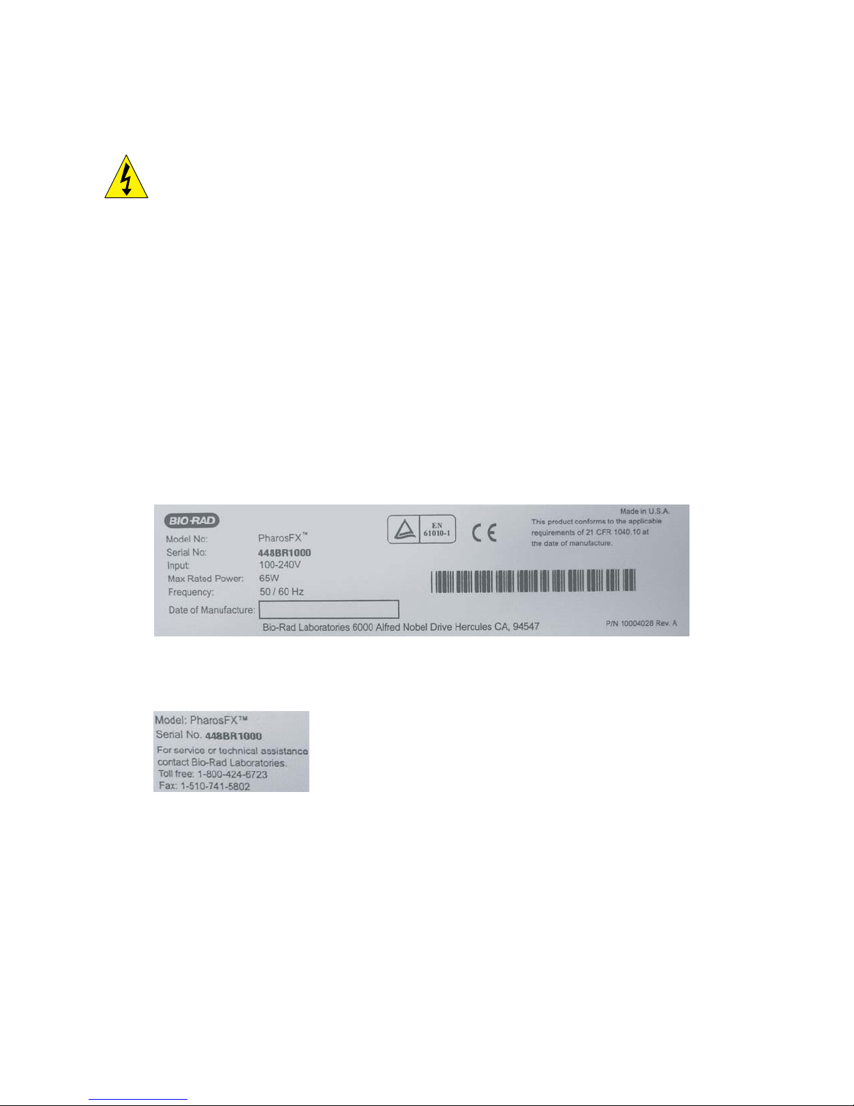
Figure 1.1 shows two serial number certification labels. These are found at the rear of the
PharosFX system and the rear of the External Laser. This label provides manufacturing
data about the instrument, its voltage settings and CDRH compliance information.
Fig. 1.1.a. Instrument serial number information on the rear of the PharosFX Scanner.
Note: For easy customer access, serial number information for the PharosFX scanner is
also located on the right hand side of the overlay located behind the scanner door.
2
Page 7
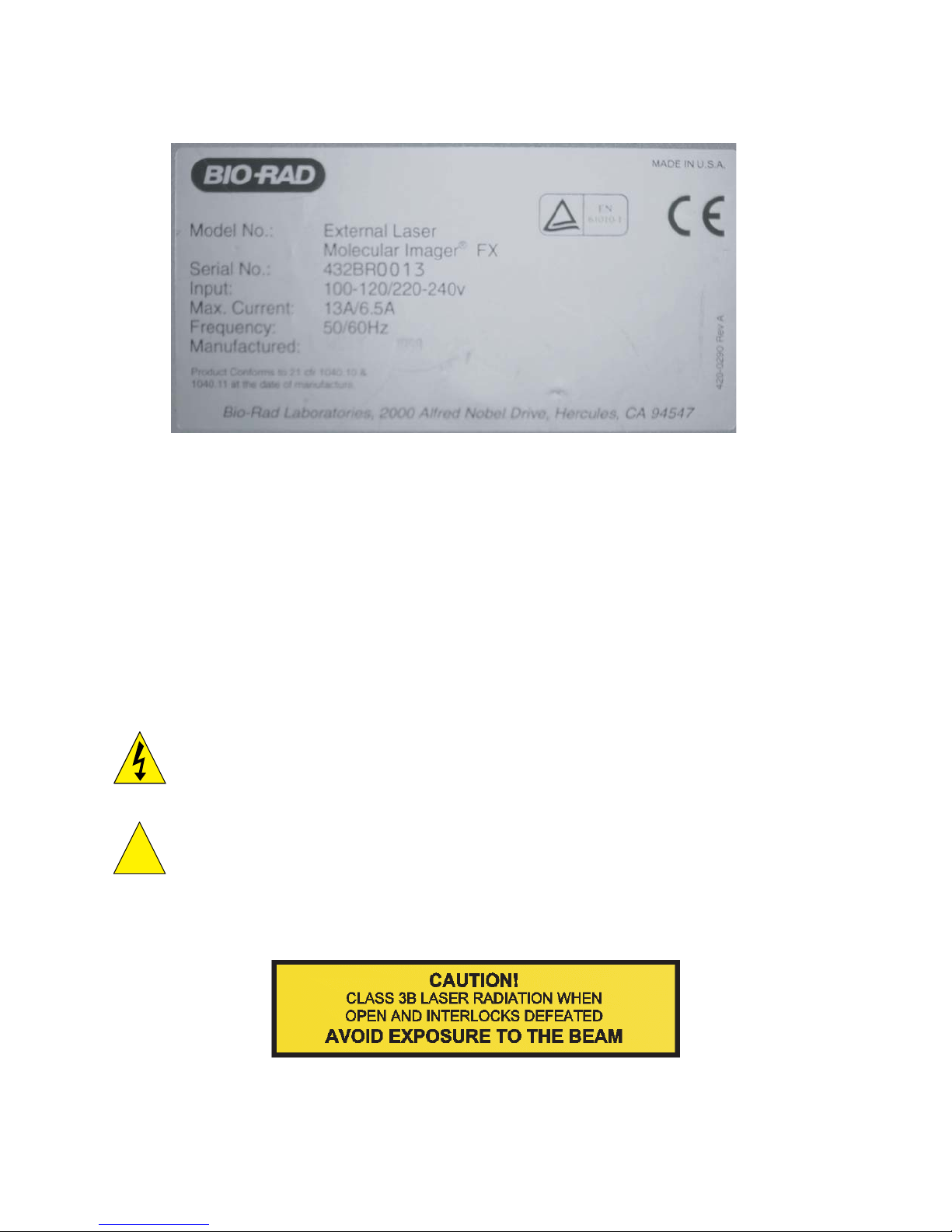
Fig. 1.1.b. Instrument serial number information on the rear of the External Laser.
1.2.4 Laser Safety Information
This instrument and its accessories are certified according to 21 CFR 1040 of the CDRH,
as a Class I laser device and IEC / EN 60825-1+A1+A2 as a class 1 laser device.
(Figure 1.1.a).
The laser contained within the PharosFX and PharossFX Plus scanning unit is configured
with a laser that generates energy up to 15 milliwatts at 532 nm. The cover of each scanner
has redundant interlocks and is designed to protect the user.
The optional External Laser Module contains an Argon-Ion laser that produces laser energy
of up to 10 milliwatts at 488 nm. This External Laser Module can also be outfitted with an
additional laser diode that produces laser energy of up to 10 milliwatts at 635 nm. The
cover of this system is designed to protect the user at all times.
Warning: Do not remove the cover for any reason or defeat the interlock. Attempting to
operate the unit with the cover removed may damage the instrument and expose the
operator to energy from the laser.
Warning: Use of controls or adjustments or performance of procedures other than those
specified herein may result in hazardous laser energy exposure.
Caution: The top cover should be removed by trained service personnel only. Do not
attempt to operate the product with the cover removed. The PharosFX system should be
serviced only by Bio-Rad or its trained representatives.
Laser warning labels (Figure 1.2) are located externally on the top cover and rear of the
instrument and internally on the top surface of the mounting plate, at the rear right-hand
corner and the top of the laser module.
Fig. 1.2. Laser warning label.
3
!
Page 8
4
1.2.5 Screen Eraser Safety Information
Warning: The Screen Eraser must be plugged into a grounded electrical outlet.
Section 2
Introduction
2.1 PharosFX System Capabilities
The PharosFX Product Family provides options for imaging and analyzing the following
sample types:
Fluorescence (for PharosFX, and PharosFX-Plus Models)
The PharosFX detects almost any visibly excited fluorescent dye. The internal and optional
external lasers allow optimal excitation of single-color or multi-color fluorescent samples.
Computer controlled filter wheels with 6 available emission filter positions allow detection of
many multi-color fluorescent signals. The system is also capable of performing sequential
detection of multiple fluorescent dyes on the same gel or blot.
Colorimetric Detection
A Transilluminating Screen, made of white plastic, is provided with the sample tray for
PharosFX and PharosFX Plus for documentation of gels stained with colorimetric stains,
such as Coomassie and Silver Stain.
Radioisotope Emissions (for PharosFX Plus Only)
Detects a broad range of isotopes, including
32
P, 33P, 35S, 14C, and 3H. The PharosFX uses
storage phosphor screen technology that is at least ten times more sensitive to isotopic
emission than x-ray film. The system is compatible with most available phosphor imaging
screens based on the BaFBr:Eu storage phosphor chemistries
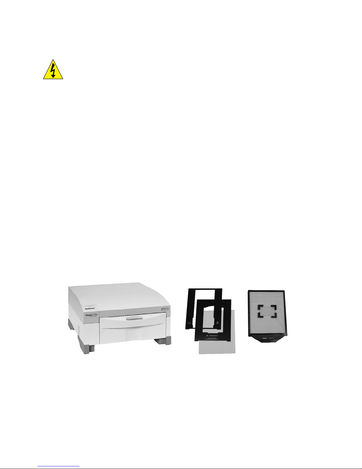
2.2 System Description
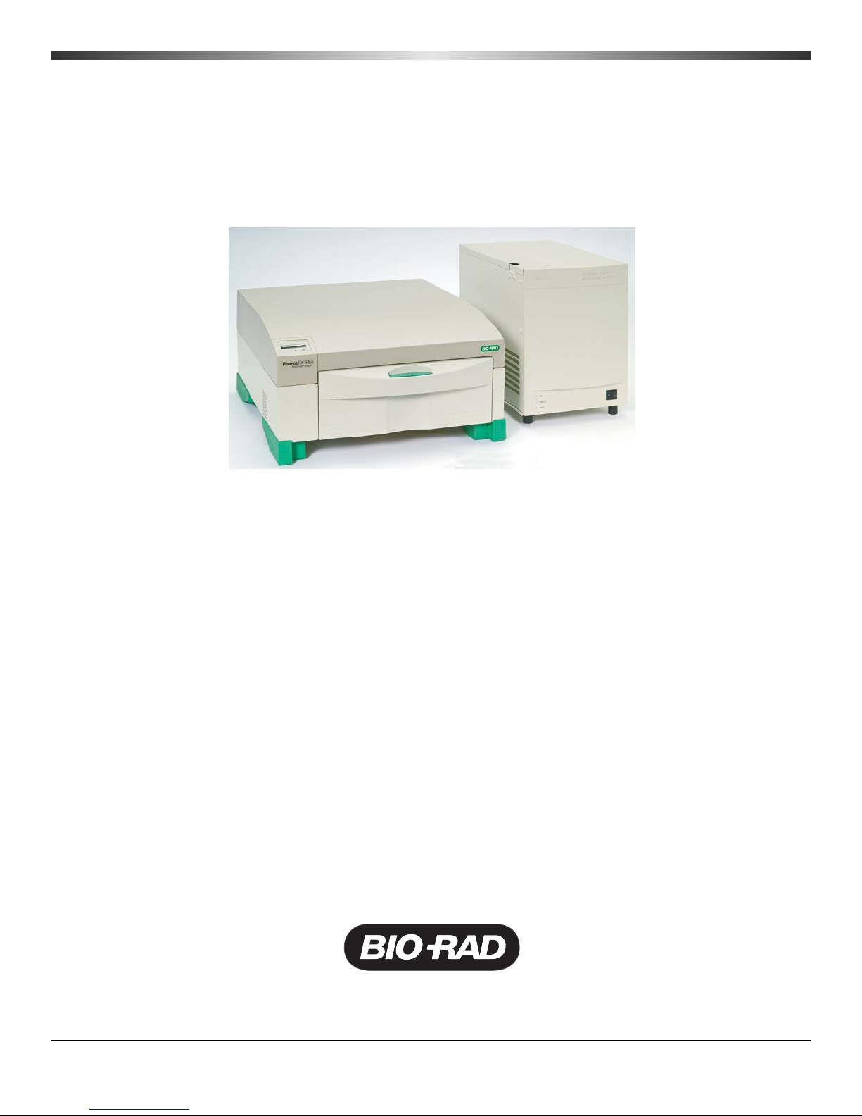
Fig. 2.1. A Typical PharosFX scanner and peripherals.
Page 9
5
The PharosFX (Plus) imaging system consists of:
• Laser scanner
• Sample Tray set, including: glass sample tray, transilluminating screen, and sample
holders
• Pre-installed filters for fluorescence detection: 640BP, 605BP, blank filter holder for
custom filters. PharosFX Plus has an additional 390BP filter for phosphor screens
• External Laser Module is optional
(1) Laser Scanner
The PharosFX and PharosFX Plus have an internal laser that emits light at 532 nm only. All
PharosFX units can scan at resolutions of 50, 100, 200, and 800 microns and have a linear
dynamic range that extends over 4.8 orders of magnitude (1:65536). In contrast, x-ray film
has a linear dynamic range that is limited to only 1.5 orders. The scanner also contains fully
automated emission filter wheels with 6 filters. These combined features permit the
PharosFX to image almost any fluorescent dye and to scan multi-color fluorescence
applications, in addition to storage phosphor imaging with the PharosFX Plus.
(2) Sample Tray
The glass Sample Tray is used as a scanning platform for fluorescent gels or blots and
K-type phosphor screens. Its spill resistant design exhibits very low background fluorescence
and high chemical resistance.
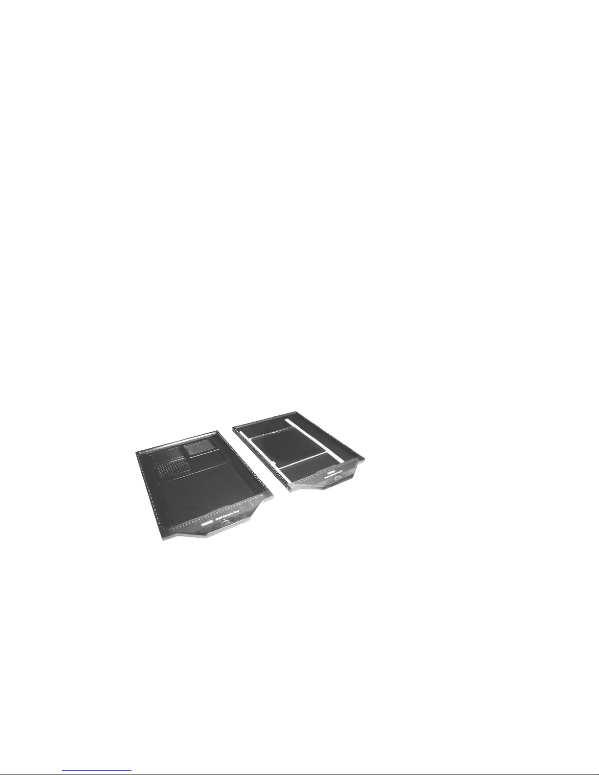
Additional Multi-Sample trays can be purchased to accommodate thick agarose gels, gels
within glass plates (1707819 Multi-Sample Tray II), metal backed storage phosphor
screens,and microtiter plates (1707812 Multi-Sample Tray).
Fig. 2.2. a) Multi-Sample Tray, b) Multi-Sample Tray II
(3) Optional External Laser Module
The optional external laser module provides one or more additional excitation source(s).
The current configurations for lasers are:
a) 488 nm Only
b) 488 nm and 635 nm
Page 10

Fig. 2.3. External Laser Module
(4) Storage Phosphor Imaging Screens
Bio-Rad offers a range of storage phosphor screens to match different user requirements.
Table 2.1 summarizes the key features of each screen. The screens are composed of a
barium fluorobromide matrix doped with europium (BaFBr:Eu); they can be used with
traditional autoradiography cassettes without a darkroom, are easy to handle and are used
solely for the detection of isotopic emissions.
PharosFX Plus offers a variety of phosphor storage applications in addition to all the
functionality of the PharosFX. All phosphor screens are reusable and unharmed by repeated
exposure to radioactivity. Screens are sensitive to β particles and X-rays. All screens are
flexible and easy to handle. Exposure takes place in standard X-ray cassettes. All phosphor
screens require erasure prior to re-exposure, and their lifetime is extended when they are
cared for properly.
Imaging Screen-K
This is a general-purpose screen designed for all common radioisotopic emitters, such as
32
P, 33P, 35S, and 14C. These screens are available in 35 x 43 cm and 20 x 25 cm formats.
Screens are guaranteed for 1 year.
Imaging Screen-K/Tritium
This is a special imaging screen available for imaging
3
H. These screens require special
care and handling and are reusable only if cared for properly. Screens are 20 x 25 cm and
are covered by a 6-month warranty.
6
Page 11
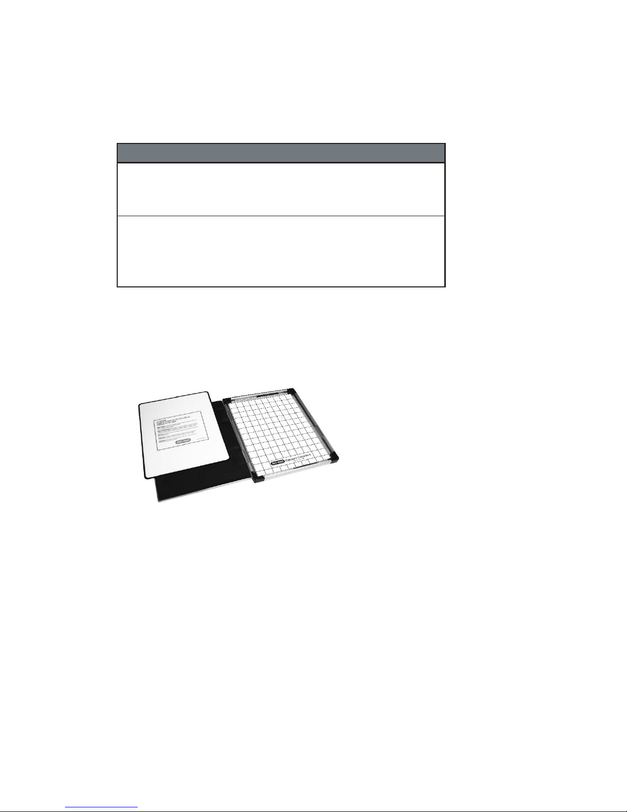
Table 2.1. Imaging Screens Specifications and Recommended
Applications
(5) Sample Exposure Cassettes
The sample exposure cassettes ensures that a close contact is made between the sample
and imaging screen. The cassettes contain a grid marked exposure area, to which the
sample is mounted. This allows the sample to be firmly pressed against the imaging screen
to generate a high quality image.
Fig. 2.4. Sample exposure cassette and phosphor screen
(6) Screen Eraser
The screen eraser removes any residual signal or background from the imaging screen.
The complete erasure process "zeros" or "blanks" the screen to a basal level, which is
critical for maximizing sensitivity, linear response, quantitative accuracy and image quality.
The Screen Eraser-K is used with the K-type screens and any other commercially available
phosphor screens which are based on the BaFBr:Eu chemistry (Fig. 2.5).
7
Screen
Name
maging
creen
maging
creen
/Tritium
Application Key Features Sizes
14
32P,33
-
-
P,
35
S
3
H
•
C,
BaFBr:Eu formulation
•
Easy-to-use format
•
Compatible with standard
X-ray cassettes
•
More durable
•
BaFBr:Eu formulation
•
Sensitive to weak
signal
•
•
Easy-to-use format
Compatible with standard
X-ray cassettes
3
H
(cm)
35 x 43
mounted
20 x 25
mounted
20 x 25 170-7845
Catalog
Number
170-7841
170-7842
170-7843
170-7844
Page 12
8
Fig. 2.5. Screen Eraser.
(7) Control and Analysis Software
Quantity One software is included with the PharosFX and PharosFX Plus systems.
Quantity One permits user-friendly, application driven control of the scanning system and
accurate 1-D analysis of the captured image data.
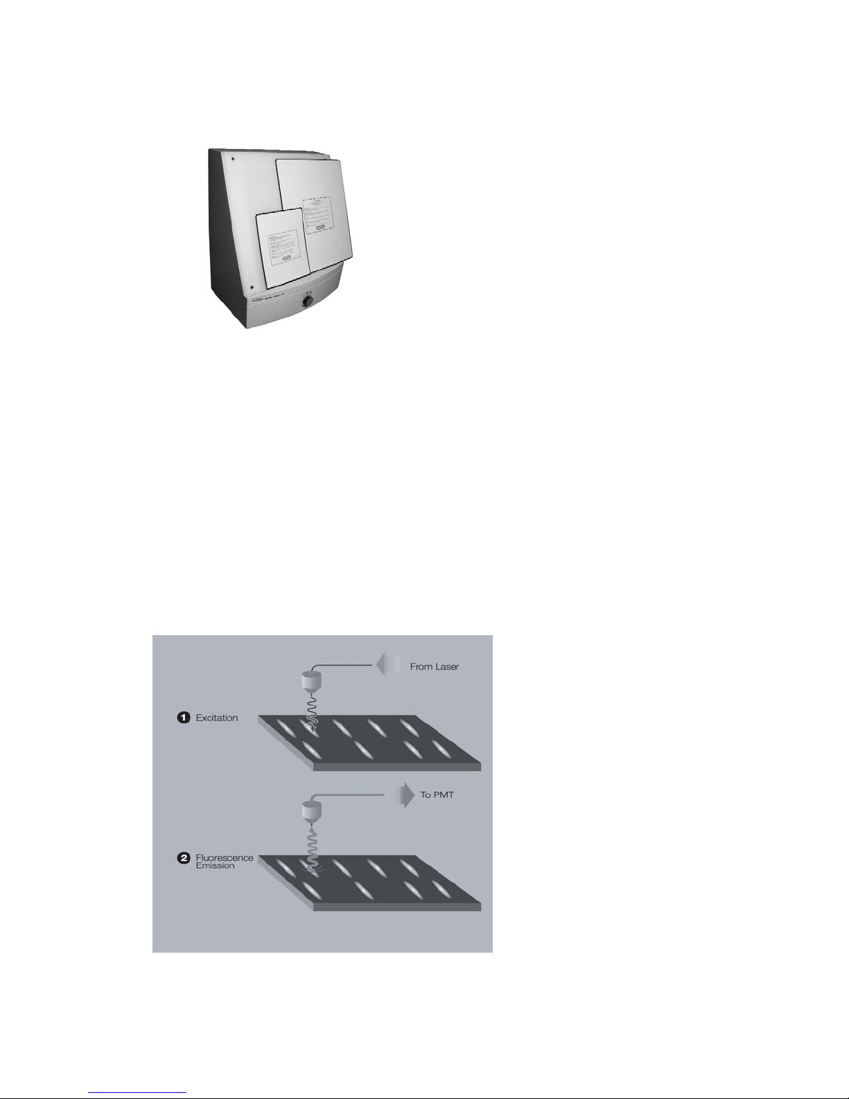
2.3 Theory of Operation
2.3.1 Fluorescence Detection Mechanism
The fluorescence process occurs when a molecule absorbs light of a certain wavelength
and excites electrons to a transient higher energy state (Figure 2.6, step 1). When the
electrons return to ground state, energy is released in the form of photon emission at a
wavelength which is longer than the illumination source (step 2). For example, ethidium
bromide (EtBr) absorbs light of 532 nm and emits light at 595 nm. Using optical filters, the
emission wavelength can be separated from the excitation wavelength and detected using
a photomultiplier tube.
Fig. 2.6. The fluorescence detection mechanism.
Page 13
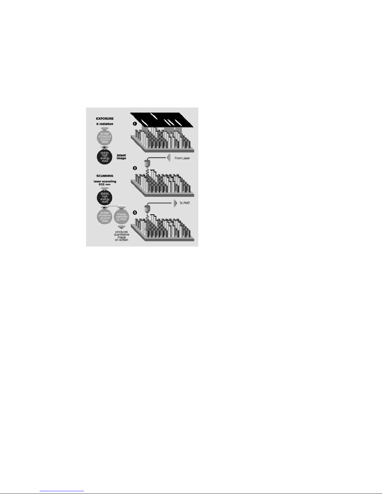
2.3.2 Storage Phosphorescence Detection Mechanism
When a radioactive emission strikes the phosphor screen, phosphor oxidation occurs and a
high-energy site is formed (Figure 2.3, step 1). When such an activated site is subsequently
illuminated with certain wavelengths of visible light (step 2), the reduction reaction occurs.
Trapped energy is released as photons that are in turn captured by a photomultiplier tube
(step 3).
Fig. 2.7. The storage phosphor detection mechanism.
Note: Storage phosphor screens are reusable after erasure.
2.3.3 Data Processing and Analysis
Phosphorescence and fluorescence signals are captured as a 16-bit digital file. This file can
then be analyzed and manipulated by the appropriate image analysis software for
visualization and quantitation.
Traditionally the image is displayed in a two-dimensional format, where the darkness of
each pixel is proportional to the signal intensity at that sample location (Figure 2.8, left). For
the purpose of image analysis however, it is helpful and more accurate to think of the data
as a three-dimensional structure, where the signal intensity at each pixel becomes the
height or z-axis dimension (Figure 2.8, right). Sample spots or bands can also be visualized
as peaks in a profile analysis along the length of a gel lane or perceived as topographic
volumes when quantitating the total signal from a specific band or spot.
9
Page 14

Fig. 2.8. Two and three-dimensional representations of a digitized image.
2.4 Overview of the Imaging Process
2.4.1 Steps in Fluorescence Imaging
The procedure for imaging fluorescent samples has four steps.
Step 1
involves thoroughly cleaning the sample tray with ethanol, using a clean soft cloth or
lint free paper towel.
Step 2
involves placement of the sample onto the tray. Several accessories, such as gel
holders, spacers and microtiter plate inserts are provided to optimize position of your sample
on the tray.
In Step 3
the tray with sample loaded is pushed into the laser scanner and the sample
imaged by direct fluorescence excitation. The host computer builds a digitized image of the
sample by tracking each pixel's signal as the scanner head moves over the screen surface.
Step 4
Once the sample image is collected, it can then be reviewed and analyzed using an
appropriate software package.
2.4.2 Steps in Storage Phosphorescence Imaging
Storage phosphor imaging is a simple four-part process. (Figure 2.9)
Step 1
involves erasing the reusable phosphor screen to remove any background or
residual image. This normally takes 10 minutes. The screens should be erased to the
background level of 100 counts or less.
Step 2
in the process involves placement of the prepared sample in an exposure cassette
for subsequent close proximity exposure to the imaging screen. The captured signal
generates a latent image of the sample, which is encoded in the number and pattern of
charged phosphor crystals.
Step 3
involves placing the screen in a laser scanner. As each pixel of the screen is
scanned, the electrons in charged areas of the latent image return to the ground state,
releasing energy in the form of emitted photons of visible light. The emitted photons are
collected and precisely counted by a photomultiplier tube, generating an intensity for each
scanned pixel. This intensity is expressed in counts or pixel density units, which are
analogous to the optical density of exposed x-ray film in autoradiography.
Step 4
is analogous to the procedure for imaging fluorescence samples, the resulting
image can then be reviewed and analyzed using an appropriate software package.
Single P i xel
10
Intensity
2-D view
3-
D view
Page 15

Upon completion of the four-step process, the storage phosphor screen can be erased and
the cycle repeated with a new sample.
Fig.2.9. Phosphor Imaging work flow
Section 3
System Installation
3.1 Operating Requirements
3.1.1 System Location
The PharosFX scanners and all peripherals should be located in an area that is free of
excessive dust or moisture, strong magnetic fields or ionizing radiation. It is also highly
recommended that the ambient temperature be stable and within the range of 10°C to 32°C
and the relative humidity not exceed 80%, noncondensing.
Laser Scanner and Host Computer
Warning: Care should be taken when lifting and moving the scanner to avoid personal
injury. It is recommended that two people, one on each side of the instrument, lift the scanner
from the bottom.
The scanner should be positioned on a level bench top with a minimum depth of 70 cm and
a height clearance of 35 cm. The scanner is 59 cm wide and you should allow additional
space for peripheral items such as screen erasers and exposure cassettes. You should
also allow easy access to the scanner power switch, which is located on the right hand side
of the unit.
The scanner should be placed where it can be easily connected to the host computer and
where there is adequate room to insert the sample tray into the front of the instrument.
The maximum distance between the host computer and the scanner should be three
meters and the system is supplied with a USB2 communication cable of this length.
Note: The host computer should be located at a workstation that minimizes operator
fatigue.
11
Page 16

External Laser Module
The External Laser Module has been designed for flexible placement. It can be located either
to the left or right of the scanner, or placed directly below the scanner in an under-bench
position. The maximum distance between the external laser and the scanner is 2 meters, as
determined by the optical fiber that connects the two instruments. Once the External Laser
has been installed and aligned it is not recommended to move it around to prevent any possible
optical misalignment.
The External Laser Module has a weight of approximately 30 kg and to avoid personal
injury the same precautions listed for the scanner should be taken when lifting the module.
The external laser should only be placed on a surface capable of easily supporting its
weight and located in a well ventilated area with 20 cm of clearance on the left hand side,
top and rear of the unit. The unit has the following dimensions: 31 cm wide, 61 cm deep,
41 cm high.
Warning: Do not position the External Laser Module inside a cupboard or similar enclosure
with poor airflow, as insufficient ventilation may cause permanent damage to the unit and
present a hazard.
Screen Eraser
The Screen Eraser has no minimum clearance requirement and may even be wall mounted, using the mounting holes located in the unit's back plate.
All screen erasers must be plugged into a grounded electrical outlet.
Sample Exposure Cassettes
The exposure cassettes do not require any power and can be placed in any convenient
location where radioactive samples are normally handled. If desired, the exposure peripherals
can be stacked or placed directly on top or under the laser scanner to conserve bench
space.
3.1.2 AC Power Requirements
The scanner and all powered peripherals including the host computer should be connected
to a stable grounded power outlet on a circuit free of electrical noise. In addition, a high
quality electrical surge suppressor/line filter with a 10 Amp or higher rating should be used
to avoid damage from AC fluctuations. Only a grounded 3-pin power cord should be used
to connect power.
The scanner is designed for input voltages of 100–240 VAC at 50-–60 Hz, and requires no
voltage setting or fuse change before operation.
The screen eraser is configured for 100–120 VAC, 50–60 Hz or 200–240 VAC, 50–60 Hz
operation. Please ensure that your eraser is configured to the appropriate voltage and fuse
settings before operation by checking the identification and settings label next to the power
input.
The External Laser Module must be configured for the proper voltage/current settings. This
should be done by appropriate Bio-Rad Service personnel only, as damage could result if
the settings are incorrect.
If the power setting on the Eraser or External Laser Module is incorrect, please contact
your local Bio-Rad representative.
12
Page 17

3.1.3 Host Computer Recommendations
The scanner is capable of producing large image files of high resolution; these can be up to
120 megabytes in size. To easily manipulate such large files, a powerful computer is
required. The host computer MUST meet or exceed the specifications as detailed below.
Table 3.1 Host computer specifications
It is recommended to have a storage device for large image files, such as a second hard
drive or CDRW connected to your CPU.
Please refer to your software manual for detailed host computer system and software
requirements. If the computer is not purchased from Bio-Rad, system compatibility is the
responsibility of the user. Please check with your local Bio-Rad office regarding compatibility for your specific brand of computer.
3.2 Setting Up Your PharosFX System
3.2.1 Shipping Check
Inspect all shipping containers to ensure that you have received all ordered items and that
no boxes are damaged. If items are either missing or damaged, report them to both the
shipping company and Bio-Rad Laboratories immediately.
The PharosFX system should arrive complete with the following items:
Remember to verify that any additional peripherals that you ordered with your PharosFX
system have been received.
3.2.2 Unpacking
For the first-time installation please call Bio-Rad Technical Support (1-800 424 6723) to
arrange a visit of a field service engineer.
13
Recommended PC Recommended Mac
Processor Pentium 333 MHz or better Power PC G3 or better
RAM >256 MB >256 MB
Hard Drive >3 GB >3 GB
Monitor 17” 1024X768 res (required)
(21” preferred)
Communications USB 2 USB 2
Operating System Windows 2000 or XP OS 10.2.8 or better
17” 1024X768 res (required)
(21” preferred)
Quantity Item
1 PharosFX Scanner with pre-isntalled fluorescence and
1 Sample Tray with sample holders, and transilluminating
1 USB2 cable
1 Power Cord
1 Hardware Instruction Manual
1 Warranty Card
1 Quantity One software (single user license)
phosphor screen filters (PharosFX Plus only) and blank
filter holders
plate
Page 18

14
Unpacking the Laser Scanner and Tray
Note: Explicit packing/unpacking instructions are located in a clear document envelope
attached on the outside of the shipping container. Refer to these instructions at all times
prior to unpacking or packing.
Unpack the laser scanner by following the steps below:
1. Cut the metal strap on the instrument packaging
2. Slide the cardboard cover off vertically
3. Remove the front and rear packaging
4. Grip the bottom of the scanner on both sides and place on the bench top.
Warning: Get a helper; a single person should not attempt to lift the scanner.
Warning: Always lift heavy objects with bent knees and a straight back to avoid back
injury.
Caution: Do not supply power to the scanner until the system has been set up following
the installation procedures and the scan head locking screw has been removed. Failure to
remove the locking screw before starting the scanner may damage the instrument.
Note: Retain all packaging materials for future transport of the PharosFX system.
Unlocking the Scan Head
To protect the scanning mechanism during transport, the scanner uses a scan head locking
screw. The screw, which is located at the rear left-hand side of the instrument, restrains the
scan head during transport and must be removed before power is supplied to the scanner.
If the screw is not removed the scanner may be damaged. To remove the locking screw,
follow the procedure outlined below. Refer to figure 3.1 #1 through figure 3.1 #5.
1. Unscrew the metal locking screw by carefully rotating in a counter-clockwise direction.
This will disengage the screw from the scan head.
2. Unscrew the black plastic screw guide by rotating in a counter-clockwise direction.
3. Remove the complete locking screw and guide assembly.
4. Remove the threaded sealing plug located in the storage hole directly below the locking
port.
5. Insert the plug it into the locking port and tighten by clockwise rotation. Insert the locking
screw and guide into the storage hole and tighten by clockwise rotation.
To lock the scan head for future transport; turn on the scanner, this will home the scanning
head. With the power "ON" reverse the procedure listed above.
!
Page 19

15
1. 2.
3. 4.
5.
Fig. 3.1. Steps for unlocking the scan head.
Unpacking the Imaging Screens
K-type imaging screens are shipped in a sealed cardboard box. The phosphor matrix is
protected by a sheet of paper that must be removed prior to erasure and use.
Retain all packaging for screen storage.
3.2.3 Electrical and Communication Connections
Power
Insert the power cord into the power entry module on the rear panel of the scanner. The
scanner uses a universal power supply and can be used with any voltage between 100 and
240 VAC.
For the screen eraser, confirm that the voltage setting on the power entry module is correctly
configured for your country. If the eraser is not correctly configured contact your local Bio-Rad
representative.
Page 20

USB2 Connection
The laser scanner must be connected to the host computer via a USB2 interface (Figure 3.2).
The USB2 link ports are located on the right-hand side of the rear of the scanner unit. The
appropriate USB2 cable is included with the scanner.
Fig. 3.2. View of USB2 connection
3.2.4 Quantity One Software Installation
Please refer to your software instruction manual for comprehensive software installation
procedures.
Section 4
Operating the PharosFX System
4.1 Starting the PharosFX Scanner
To turn on the PharosFX scanner, press the power switch located on the right side of the
instrument. The LCD display on the front of the scanner displays internal diagnostic data
and information relating to the instrument version (Figure 4.1). When the power is first
turned on the LCD should display the sequence of messages shown below. This process
takes approximately 40 seconds.
Start-up Display Sequence
1. Start Up
2. Main (Revision) v. x.xxx
3. Detector v. x.xxx
4. Laser v. x.xxx
5. Ready
When the Ready message is displayed, the host computer can communicate with the
scanner.
Note: If any other messages are shown after 2 minutes, or if the scanner is inoperative or
the scanner acquisition window cannot be opened on the host computer, please contact
your Bio-Rad Technical Service Department for assistance (1-800-424-6723 press 2 for
Technical Support).
It is recommended that the PharosFX scanner be allowed to warm-up for 15 minutes
before use. It is generally recommended that the scanner be left on, unless it is not going to
be used for a period of more than 48 hours.
16
Page 21

17
Fig. 4.1. PharosFX LCD and control panel.
An LCD "Contrast" button is located on the control panel (Figure 4.1). This button can be
used to adjust the brightness of the LCD display. The contrast function cycles so that
holding the button down will cause the display to get lighter and then darker again.
The "On Line" button on the control panel should be depressed only in the unlikely event
that the acquisition software cannot halt scanner operation.
4.2 Fluorescence Detection
4.2.1 Sample Preparation
Prepare fluorescent samples as recommended by published protocols. The following sample
types can be imaged using PharosFX and PharosFX Plus.
Agarose Gel
Acrylamide Gel
Acrylamide Gel sandwiched between two glass plates
Acrylamide Gel on top of a single glass plate
Membranes and Blots
Hybridized Glass Plates
Microtiter Plates
Page 22

18
Table 4.1
Sample Preparation and Accessories
Caution: When using the glass sample tray the maximum sample thickness must not
exceed 8 mm. The sample tray cannot be inserted into the scanner with a sample thicker
than 8 mm. The height of the side rail on the tray can be used as a guide to determine the
maximum sample thickness, as the sample's height must not exceed that of the side rail.
Thicker samples, up to 17 mm, can be imaged using the Multi-Sample Tray I (1707812) or
Multi-Sample Tray II (1707819).
4.2.2 Inserting a Fluorescent Sample into the Scanner
1. Open the front door of the scanner.(Figure 4.2)
2. Pull out the glass sample tray and, if dirty, clean with a dry lint-free cloth.
3. Carefully place the prepared gels or blots onto the tray, making sure that the fluorescent
signal is directed upwards. (Maximum sample thickness is 8mm.)
4. Note the coordinates of the sample on the tray for reference when selecting the desired
scan area in the software. The grids with coordinates on the tray in the software match.
Accessory Use for Preparation Notes
Sample Tray
170-7811
Multi-Sample Tray
170-7812
Multi-Sample Tray II
170-7819
•
Agarose Gels
•
Acrylamide Gels
•
Blots/Membranes
•
Colorimetric Gel
Documentation
•
Unmounted Storage
Phosphor Screens
•
•
•
•
•
Mounted Screens (MD
format)
Microtiter Plates
Acrylamide gels
sandwiched between
glass plates.
Acrylamide gels sitting
on glass with no top
glass plate.
TLC plates
•
No gels thicker than 8 mm.
•
Gels should be wet.
•
Blots/Membranes should be moist.
•
Use Sample Holders (170-7813) to
keep sample from moving during scan.
•
When performing Colorimetric Gel
Documentation work, utilize the
transilluminating screen supplied.
•
Will accept unmounted screens from
many manufacturers including BioRad, Kodak, MD and Fuji.
•
When working with 20 x 25 cm small
format screens (170-7843) utilize the
alignment overlay supplied with the
Sample Tray.
•
•
•
•
•
•
•
•
Face MD screens upward inside the
tray.
When scanning Microtiter Plates use
the Microtiter Adaptor Assembly (170-
7814).
Microtiter Adaptor As
up to 8 microtiter plates.
Plates that can be scanned include 96,
384 and 1536 wells.
Make sure prior to preparing samples
that the microtiter plate format can fit
inside the scanner when used with the
Multi-Sample Tray/Microtiter Adaptor
Assembly.
Make certain that the thickness of the
sample and the glass plates fits within
the scanner prior to scanning.
The Multi-Sample Tray II ships with
three sets of non-slip spacing strips.
Use these to determine your optimal
focus for Differential Display
workscanning.
Utilize the Print 1:1 function to aid in
any incision work for Differential
Display processes.
sembly accepts
!
Page 23

5. Slowly insert the tray with the sample all the way into the scanner, until the hold latch
engages and you hear a click.
6. Close the front door of the scanner.
7. The sample can now be scanned using the acquisition software.
8. To remove the tray, simply wait until scanning is complete, open the scanner door and
pull the tray out.
Note: For wet samples, use a clean, lint-free absorbent paper towel to remove excess liquid
from around the sample. This will reduce the potential for the gel to slide on the sample tray
and move during image collection.
Note: It is recommended that samples be placed against the edge of the tray to ensure
straight alignment.
Note: Gel holders may also be placed at opposite corners of the sample to prevent
movement during tray insertion.
Fig. 4.2. Steps for inserting a fluorescent sample into the scanner.
4.2.3 Scanning Fluorescent Samples
1. Open the scan window in the acquisition software. Under the File menu, choose
PharosFX. In the acquisition window choose Select and use the layered menu to identify your application and sample strength. (i.e. for an ethidium bromide stained DNA
sample of low concentration, select Nucleic Acid Stain>Ethidium Bromide>Low
Sample Intensity).
2. The emission filters choice is specified through the software.
3. Choose the scan area that you would like to image.
4. Select the desired resolution setting. The highest resolution is 50 µm and the lowest is
800 µm.
5. Select Acquire to begin scanning. The scanning is performed sequentially. A single
frame is scanned for a selected fluorophore.
Note: Refer to the Software Manual for detailed acquisition instructions.
Caution: Do NOT open the door of the scanner while the unit is scanning. This will terminate
your scan and require you to rescan your fluorescent sample.
6. When the scanning is complete open the door of the PharosFX.
7. To remove the sample, simply pull out the tray and lift it off.
19
!
Page 24

4.2.4 Inserting Additional Excitation and Emission Filters
PharosFX and PharosFX Plus are supplied pre-configured with emission filters that support
most common fluorescence applications and as such, users should not routinely have to
access the filter areas. If users wish to install additional filters and perform custom
fluorescence experiments this can be easily done as the emission filter wheels can be
accessed through the port in the scanner's front panel (Figure 4.3).
Fig. 4.3. Access port for emission filter cubes
Selecting Different Filter Positions
The filter wheel advance switch located on the front panel of the scanner can be used to
rotate the two emission filter cubes (Figure 4.4). To activate the switch, simply depress
once for each turn required.
Fig. 4.4. Selecting a filter position using a filter wheel advance switch.
Caution: Do NOT hold down the filter wheel advance switch. To rotate the filters users
should quickly press and release the button once. Users should allow the filters to move to
the next position before activating the switch again.
Caution: Do NOT manually rotate the filters. This may result in misalignment of the
excitation filter wheel and emission cubes. It may also cause permanent damage to the filter
driver motors. Always use the advance filter wheel switch to change filter positions.
Adding or Changing an Emission Filter
1. Open the front door of the PharosFX scanner.
2. Unscrew the two black screws holding the emission filter port cover in place and
remove the cover.
20
!
Page 25

3. Depress and release the filter wheel advance switch until the desired emission filter
location is presented. Filter cubes are identified by a wavelength and catalog number
label, which should be clearly visible.
4. If a filter cube is to be removed from the slot do so by gently pulling the cube towards
you
5. To install a new filter, hold the cube with the mounting slots on the left hand side. Align
the cube's mounting slots with the guides located on the filter wheel and gently push
the cube onto the guides.
6. Replace the filter port cover and tighten the two black retaining screws.
7. Note the filter position in order to configure the application and select it correctly in
Quantity One.
Note: Do not operate the scanner with the filter port cover removed.
Fig.4.5. Emission filter port
Fig. 4.6. Adding a new emission filter.
21
Page 26

The standard emission filter configurations are as follows:
Table 4.2
Note: When a 488 Excitation Option is ordered an additional 530 Bandpass Filter is
supplied (e.g. FITC and Cy2). When a 635 nm Excitation Option is ordered an additional
695 Bandpass Filter (e.g. Cy5) is supplied. The recommended filter positions are indicated
in table 4.2 above.
4.3 Fluorescence Imaging Using the External Laser Module
The optional External Laser Module can be attached to PharosFX and PharosFX Plus to
expand the system's range of laser excitation sources. The installation of the External
Laser Module requires a field service engineer, please arrange the visit through Technical
Support (1-800-424-6723 press 2 for Technical Support). The standard external module
contains an Argon Ion laser, which is ideal for imaging fluorophores excited by 488 nm
light. The External Laser Module can also be outfitted with an additional 635 nm laser,
which further adds to the flexibility of the PharosFX imaging system.
The PharosFX Scanner detects when the External Laser Module is attached and the
External Laser will be used whenever the appropriate application is selected.
22
532
PharosFX
Filter
Wheel A B A B A B
PharosFX Plus
Filter
Wheel A B A B A B
only
605 nm
1 Blank
2 Blank Blank 2 Blank Blank 2 Blank
640 nm
BP
3
4 Blank Blank 4 Blank Blank 4 Blank Blank
532 only
1 Blank
390 nm
BP
2
640 nm
3
BP Blank 3
4 Blank Blank 4 Blank Blank 4 Blank Blank
BP
Blank 3
605 nm
BP 1 Blank
Blank 2
filter can not be changed.
532 &
488
1 Blank
640 nm
BP
532 &
488
390 nm
BP
640 nm
BP
1 Blank
3
1 Blank
3
532, 488 & 635
640 nm
BP
532, 488 & 635
390 nm
BP
640 nm
BP
605 nm
BP
530 nm
BP
605 nm
BP
Blank 2
530 nm
BP
605 nm
BP
695 nm
BP
530 nm
BP
605 nm
BP
695 nm
BP
530 nm
BP
Page 27

Fig. 4.7. PharosFX External Laser Module connected to the scanner
4.3.1 External Laser Safety Information
The External Laser Module (Figure 4.7) is certified according to 21 CFR 1040 of the CDRH,
as a Class I laser device. The laser contained within the External Laser Module produces
10 milliwatts at 488 nm. This laser can also be upgraded to include a 635 nm laser
producing up to 10 milliwatts at 635 nm. The cover of the system is designed to protect the
user and should not be removed.
Warning: Do not remove the cover for any reason or defeat the interlock. Attempting to
operate the unit with the cover removed may damage the instrument and expose the
operator to laser energy from the laser.
Warning: Use of controls or adjustments or performance of procedures other than those
specified herein may result in hazardous laser energy exposure.
Caution: The cover should be removed by trained service personnel only. Do not attempt
to operate the product with the cover removed. All PharosFX components should only be
serviced by Bio-Rad or its trained representatives.
4.3.2 Fiber Optic Cable Alignment on the External Laser Module
The PharosFX system incorporates a motorized driver, which self-aligns the fiber-optic to
optimize the illumination signal. Whenever a user selects an external laser source that is
different than the last laser used the auto-alignment process is automatically performed.
Caution: Any movement of the metal sheathed fiber-optic cable will affect the efficiency of
light transfer from the External Laser Module to the PharosFX or PharosFx Plus system. As
such, it is recommended that the cable not be moved during image acquisition.
23
!
!
Page 28

4.4 Phosphor Imaging Procedures
4.4.1 How to Prepare K-Type Imaging Screens
Fig. 4.8. K-type imaging screens.
All K-type imaging screens (K, K-HD, K/Tritium) are not erased prior to shipment from the
factory and should be erased for 20 minutes prior to first use. Subsequent erasures should
only take 10 minutes.
Note: Optimal image quality and sensitivity can only be achieved with a thoroughly erased
screen.
Caution: The captured signal (latent image) stored on a K-type screen can be partially
erased when the screen is exposed to fluorescent room light. Users should rapidly transfer
the screen from the exposure cassette to the laser scanner. Some users choose to dim the
room lights to prevent accidental erasure.
When screens are not in use, they should be placed in the original shipping box provided
and placed in a dry and dark environment.
Caution: The phosphor surface of the screen is sensitive to damage from moisture,
mishandling and improper use of solvents. For detailed instructions on how to maintain the
K-type imaging screens, please refer to the Care and Maintenance section of this manual
(Section 5.2.).
4.4.2 How to Erase Imaging Screens
The screen eraser (Figure 4.9) contains a series of bulbs that produce light that is a specific
wavelength range. When illuminated with this light, the phosphor crystals in the screen
discharge, returning to ground state. As a result, any screen background or residual signal
is removed.
Fig. 4.9. Screen Eraser.
24
!
!
Page 29

25
To erase the imaging screens, place the imaging screen against the front panel of the
Eraser-K with the white phosphor side facing the white diffuser plate of the unit. Set the
timer to the desired setting or to erase continuously set the timer to the HOLD position.
The erasure process typically requires only 10 minutes, assuming the previous sample has
not charged the phosphor in the screen above 20,000 pixel density units. An erasing time
guideline is shown in Table 4.3.
Note: The screen will not be damaged by extended erasure.
Note: Erasing the screen to the basal level is critical, since this has a direct effect on the
sensitivity, linear response, quantitation, exposure time and image quality.
Erasure Guidelines
Table 4.3. Recommended erasure times.
4.4.3 How to Prepare Samples
The recommended phosphor screen exposure time can be estimated, based on one-tenth
of the time it would normally take to visualize the sample on x-ray film.
Dry Radioactive Samples
Dry thin samples such as nitrocellulose membranes, dried gels or TLC sheets can be
exposed directly to the imaging screen in the exposure cassette (Figure 4.10). Ensure that
TLC plates are completely dry before placing them against the screen and always cover
with plastic wrap to prevent flecks from contaminating the screen.
When imaging thick samples it is recommended that the screen is simply placed face down
against the sample on a flat surface and the exposure is conducted in a light-tight drawer
or other dark location.
Note: It is important when placing the screen against the sample, that the samples are
correctly aligned the first time. Adjusting the screen after placement against the sample
may result in a ghost image or double exposure. If the screen needs to be realigned it must
first be erased.
Note: If you are exposing the screen to a frozen sample, the screen should first be sealed
in a plastic bag as condensation may cause screen damage. After exposure the screen
should be equilibrated to room temperature before the bag is opened and the screen
removed.
Caution: Never expose screens to organic solvents or acetic acid vapors as these may
cause screen damage even when the sample is covered with plastic wrap.
Caution: Samples should not contain either scintillants or enhancers, as these will interfere
with the operation of the screen.
Condition Background
Before each exposure 1-20,000 10 minutes
After high dosage
exposure
(PD units)
>20,000 20 minutes
Time
!
Page 30

Fig. 4.10. Imaging Cassette.
A protective sheet should be placed between the sample and the screen to minimize the
chance of radioactive contamination (Figure 4.11).
Fig. 11. Use of protective sheet in Imaging Cassette.
Wet Radioactive Samples
Precautions must be taken to prevent wet samples from contaminating the imaging screen.
Wet thin samples should be completely enclosed in a heat-sealable bag and moist samples
must be covered with plastic wrap before being exposed to the imaging screen.
Caution: Direct contact of a wet sample with the imaging screen may cause irreversible
screen damage.
Caution: Alkaline denaturing gels must be neutralized before being wrapped and exposed
to the screen.
Caution: Never expose the K/Tritium screens to wet samples, even if they are covered.
26
!
Page 31

Plastic wraps will attenuate weak beta radiation signals according to the following table.
Table 4.4 Attenuation of radiation by various plastic wraps.
Note: When enclosing a sample in plastic wrap or a heat-sealable bag, make sure that
there are no large air bubbles or surface wrinkles on the side of the sample that will come
into contact with the screen. Air bubbles and wrinkles will prevent close contact with the
screen, which may result in poor image quality and reduced sensitivity.
Note: Ensure that the external surface of the wrap or heat-seal bag is wiped dry to minimize
potential screen contamination.
4.4.4 How to Use the Exposure Cassette
Exposure Cassette-K
Fig. 4.12. Steps in use of the Exposure Cassette-K.
1. Push the two release buttons away from the edge of the cassette to open.
2. Use a clean cloth to wipe the internal surfaces of the cassette and remove any
contamination.
3. Tape the prepared sample with the active surface facing upwards to the grid marked
exposure pad, making sure to align the sample straight and in the correct orientation. It
is recommended that plastic wrap is then taped in place over the sample.
27
Wrap Type
2 mm Seal-A-Meal Bag 16% 82% >99.9% Wet samples
0.5 mm Saran Wrap 6% 50% 99.7% Moist samples
32
P
14
C
3
H Application
Page 32

4. Place the Imaging Screen-K directly on top the sample with the phosphor (white) side
facing down onto the sample. It is recommended that the sample is at least 1 cm from
all edges of the screen to prevent possible edge effects.
5. Make a note of the sample's upper-left and lower-right grid coordinates for later use in
selecting the scan area.
6. Close the cassette and press until the release button catches and a snap sound is
heard.
4.4.5 How to Scan the Imaging Screen
Inserting K-Type Screens into the Scanner
1. Open the scanner door on the front of the instrument.
2. Insert the sample tray if it is not already in the scanner.
3. Remove the imaging screen from the exposure cassette and quickly place it on the
sample tray with the phosphor surface facing upwards.
Note: When transferring the screen from the exposure cassette to the scanner operator
should minimize exposure to direct fluorescent light, as this may erase some of the collected
signal. Some users choose to dim room lights during the transfer process.
Note: When scanning a small sized screen it is recommended that the appropriate location
template be used. This template will correctly align the screen and will simplify the selection
of scan coordinates. The template will also prevent the screen from moving out of position
during insertion of the sample tray.
Note: Do not bend the screen as this may damage the phosphor material.
4. Insert the sample tray with screen completely into the scanner so that it engages the
locking clip and you hear a click. (Figure 4.13)
5. Close the scanner door.
28
Page 33

Fig. 4.13. Steps for inserting a phosphor screen into the scanner.
Scanning the Radioisotopic Samples
1. Open the scan window in the acquisition software. Under the File menu, choose
PharosFX Plus. In the acquisition window choose Select and use the layered menu to
identify your application. (i.e. for radioisotopes using the Imaging Screen-K, select
Radioisotopes/ K-Screen).
2. Choose the scan area that you would like to image.
3. Select the desired resolution setting. The highest resolution is 50 µm and the lowest is
800 µm.
Note: Scanning phospor screens is a data destructive process so only one accurate scan
can be performed per sample exposure.
4. Select Acquire to begin scanning.
Note: Refer to the Software Manual for detailed acquisition instructions.
Caution: Do NOT open the door of the scanner while the unit is scanning. This may
terminate your scan prematurely and result in the loss of image data.
5. When the scanning is complete open the door of the PharosFX Plus.
6. To remove the imaging screen, simply pull out the sample tray and lift off the screen.
7. Once removed, imaging screens can be immediately erased and reused.
29
!
Page 34

30
Section 5
Care and Maintenance
5.1 Scanner Maintenance
With regular use the PharosFX scanner should provide years of trouble-free operation,
without the need for operator maintenance. If you suspect that the PharosFX system
requires servicing, please contact your local Bio-Rad office.
It is recommended that the casing of the scanner be periodically inspected to verify that no
panels are loose or distorted.
Caution: Do not remove the cover from the PharosFX system, as this voids the warranty.
There are no user-serviceable components in the scanning unit. Attempting to operate the
product with the cover removed may damage the instrument and expose the operator to
laser energy. The PharosFX system can only be serviced by Bio-Rad or its trained representatives.Use only mild, non-abrasive and water-based detergents to clean the external
surface of the scanner.
5.2 Care for PharosFX Plus Accessories
5.2.1 General Care of Imaging Screens
Utmost care should be taken to ensure that the protective plastic covering over the
phosphor matrix is not damaged. The phosphor crystals are hygroscopic and any holes,
nicks or punctures in this environmental barrier will eventually cause damage to the
phosphor and render that portion of the screen unusable. For the same reason the imaging
screen should never be directly exposed to wet gels or chemicals. Use some water-impermeable media between a wet sample and the phosphor screen (e.g. "Saran Wrap™").
Never expose the screen to acids, acid vapors or other organic solvents.
Never bend the screen as this may damage the phosphor matrix.
5.2.2 Radioactive Contamination Check
If you suspect that a storage phosphor screen has been contaminated, follow the procedure
outlined below to confirm this.
1. Clean (see Section 5.2.3) and erase the screen to background levels.
2. Check for complete screen erasure by scanning at 800 microns.
3. Place the screen in a dark area such as a lab drawer for 6 to 24 hours.
4. Re-scan the screen at 800 microns.
5. Use Quantity One software to check the screen background counts. If no areas of high
signal (hot spots) are detected, erase the screen and use.
Any contamination will be visible as a localized region of high signal over background (hot
spots). If there is contamination, clean the screen as described below and clean the grid of
the exposure unit. Screen contamination can be minimized by using plastic wrap as a physical barrier to separate the phosphor screen from the radioactive sample.
5.2.3 Cleaning Imaging Screens
If contaminated, the screens should be cleaned to remove any radioactive contamination,
sample residue or dust.
!
Page 35

31
Caution: Do not use powdered detergents to clean the screen as undissolved particles
may damage the screens coating.
Cleaning Protocol for Imaging Screen-K and Imaging Screen-HD
1. Handle the screen only by the edges. Avoid touching the screen coating with anything
sharp, such as fingernails. The screen is coated with a thin layer of plastic and
scratching this protective layer could damage the screen, making that area unusable.
2. Apply a small amount of cleaner to a soft, lint-free-cloth and gently wipe the screen. It is
recommended to use Kodak Intensifying Screen cleaner and Antistatic Solution
Catalog# 1064930 from Kodak.
3. With a dry section of the cloth, gently wipe the screen to remove any excess moisture.
If the screen had radioactive contamination, properly discard the radioactive cloth.
4. Erase the screen to background before use.
5. Repeat the contamination check above.
Cleaning Protocol for the Imaging Screen K/Tritium
Caution: The phosphor matrix of the tritium screen has no protective barrier and should
NOT be cleaned with or exposed to any liquids.
Any particulate matter should be gently removed with a soft, dry brush or gentle dry gas
stream.
The screen should be used only with ³H, any other isotope will contaminate the screen.
5.2.4 Storage of the Imaging Screens
Always erase the screen prior to storage. The surface of the screen should be completely
protected. Do not place heavy objects on top of the imaging screen. With proper care the
imaging screen should maintain its performance through years of use.
Always store the screen "flat" in an exposure cassette, in the original shipping box or storage
bag.
5.3 Exposure Cassette Maintenance
These devices do not require regular maintenance other than regular cleaning to remove
any residue or possible radioactive contamination. To clean, wipe with a lint-free paper
towel moistened with a mild detergent solution such as Bio-Rad's Cleaning Concentrate
(Catalog #161-0722) that has been diluted 1 in 20 with distilled water.
5.4 Screen Eraser Maintenance
The white plastic filter requires occasional cleaning to remove accumulated dust from its
surface. To clean the filter, gently wipe with moist, lint-free paper or a soft cloth. Do not use
abrasive cleaning solutions, as they will scratch the filter.
5.4.1 Changing Bulbs
To order replacement bulbs (Catalog #170-7869) contact either Bio-Rad Laboratories or
your local distributor.
The Screen Eraser uses four 15-watt fluorescent light bulbs. To replace a light bulb, use
the following procedure.
1. Determine the defective light bulb.
!
!
Page 36
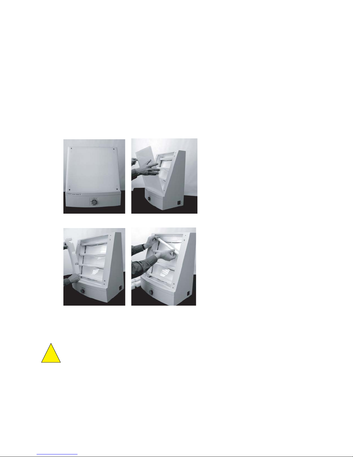
2. Turn off the eraser.
3. Wait five minutes for the bulbs to cool.
4. Unplug the power cable.
5. Open the four hex screws on the front of the eraser, using the hex tool stored on the
rear panel of the unit.
6. Remove the white plastic filter.
7. Remove the foam on both sides and replace the defective bulb.
8. Reassemble by reversing steps 4 to 7.
Step 6.
Step 7a Step 7b
Fig. 5. Screen Eraser bulb replacement steps.
Caution: Use only 15 W bulbs. Higher wattage bulbs can damage the imaging screens
and weaker bulbs will not erase the screens effectively.
32
!
Page 37

Section 6
Troubleshooting
6.1 Factors Affecting Image Quality
Fluorescent samples
Resolution
Any movement of the sample during scanning can cause a blurred image. Be sure that
excess liquid around gel samples is removed and that the imager is level. Sample holders
are supplied with the glass sample tray. These have suction feet that allow attachment to
the glass and will hold samples in place.
Sample height will affect the resolution of the image. The optics of the scanner are
designed to allow for some variation in sample thickness but samples greater than 3 mm
thickness or on a substrate such as glass or plastic plates are optimally imaged using the
optional Multi Sample Tray II. This tray comes with variety of spacers that allow the sample
to be positioned at the optimal imaging height. See the Multi Sample Tray instructions for
further details.
Sensitivity
Fluorescent intensity can vary greatly between samples and require changing the PMT
voltage. Three standard PMT settings exist for all fluorescent applications, High, Medium,
and Low Sample Intensity. These represent PMT voltages of 25, 35, and 45% of maximum
respectively. The higher the PMT voltage, the greater the signal amplification. Therefore,
with a sample that has a strong fluorescent signal, the PMT voltage should be lower than
for a sample with a weak fluorescent signal. Empirical testing of the proper PMT setting is
required to obtain the best quality image. If the preset PMT voltages are not satisfactory, a
custom application can be made using a voltage other than what is available through the
preset applications. Consult your software manual for details of creating a custom
application.
Placing samples on substrates other than the provided sample trays can produce excessive
background fluorescence. High background fluorescence will negatively impact sensitivity.
Testing any other substrates with the same imager settings intended to be used for sample
scanning will identify potential problems.
Radioactive samples
Resolution
Close contact of the sample with the active surface of the imaging screen is critical for
producing the highest quality image. Remove excess layers of tape, air bubbles or wrinkles;
these may produce only a very small gap, but this is sufficient to produce a fuzzy image.
Samples that are over-exposed will result in images with low resolution. If this occurs,
erase the screen and expose for a shorter time.
High background on a screen can cause decreased resolution of weak signals. Ensure that
the screen is thoroughly erased before imaging your sample.
The phosphor screen is very sensitive to isotope emission, as such, place the screen evenly
over the sample and do not move once it has been aligned, as this may result in a ghost or
double image.
33
Page 38

Sensitivity
Optimal sensitivity can only be achieved with a thoroughly erased screen. Close contact of
the sample with the screen will also impact the imaging sensitivity. Ensure that the sample
is pressed close to the screen surface.
6.2 Problem Solving Guide
34
Problem Possible Cause Solution
Scanner is not
responding to host
computer
Image is not visible
on the monitor
Scans have image
artifacts
Scans have speckled
images.
Scanner door is open
•
Scanner is not on-line
•
USB cable is not connected
•
to scanner or computer
USB cable is defective
•
Scanner is not turned on
•
The ‘Transform” function in
•
the software is set too high
(radioisotope only)
•
Insufficient exposure time
Area where sample was
•
placed was not scanned
Radioactive contamination on
•
the phosphor surface coating
Static electricity on phosphor
•
screen
Phosphor screen may be
•
scratched or damaged
Contamination of sample tray
•
with fluorescent material
Imager is not level and
•
sample moved during scan
Diagonal line on a phosphor
•
screen image
Dust on pho sphor screen or
•
fluorescent sample
Close Door
•
Press on-line button
•
Reconnect USB cable
•
Replace USB cable
•
Turn on scanner
•
Set to a lower max imum value
•
Expose sample for a longer
•
time
Check location of sample and
•
rescan.
(radioisotopes) When imaging
small screens ensure that the
appropriate location template is
used
Check and clean using the
•
protocols in this manual
Check and clean using the
•
protocols in this manual
Visually inspect the screen
•
Clean sample tray with Bio-Rad
•
cleaning solution, verify no
residual contamination by
scanning the sample tray.
Level imager, minimize liquid
•
around sample and use sample
holders to restrain sample from
moving
The image was obtained by
•
rescanning the screen.
Insure powder free gloves are
•
used for handling screens and
samples.
Page 39

Appendix 1
PharosFX System Specifications
System Technical Specifications Specification
Linear dynamic range 1:65535
Pixel resolution 50, 100, 200 or 800 µm, selectable
Image resolution 2 line pairs/mm or 250 µm
Pixel density 16-bit (0–65,535)
Signal decay
32
P 50% retention in 24 hr
Scanning area 35 x 43 cm
Main Component Specifications
Laser Scanner Specification
Dimensions 69 (D) x 59 (W) x 30.25 (H) cm
Construction Molded plastic housing, Aluminum mounting plates
Excitation source 532nm Diode Pumped Solid State Laser 15 mW
Weight 30 kg
Electrical
Maximum power 650 Watts
Input voltage range 90–260 VAC, 50–60 Hz
Fuses No user-serviceable fuses
Operating Requirements 10–32°C, 30–80% humidity
Storage Requirements 0–60°C, 10–90% humidity
External Laser Module Specification
Dimensions 61 (deep) x 31 (wide) x 41 (high) cm
Construction Welded 16 Gauge steel
Weight 30 kg
Electrical
Input voltage range 100/120 VAC, 50–60 Hz
220/240 VAC, 50–60 Hz
Fuses 6.3 Amp (100/120 VAC)
3.15 Amp (220/240 VAC)
Excitation Source
Option I 488 nM, 10 mW, Ar-ion Laser
Option II 488 nM, 10 mW, Ar-ion Laser and 635 nm,
10 mW Laser Diode
Operating Requirements 10–40°C, 0–90% humidity
Storage Requirements 0–50°C, 0–90% humidity
Screen Eraser-K Specification
Dimensions 35 (D) x 48 (W) x 57 (H) cm
Construction Molded plastic
Weight 8.6 kg
Electrical
Input voltage range 100/120 VAC, 50–60 Hz
220/240 VAC, 50–60 Hz
Fuses 6.3 Amp (100/120 VAC)
3.15 Amp (220/240 VAC)
Illumination 4 x 15 Watt user-replaceable fluorescent bulbs
Operating Requirements 10–32°C, 30–80% humidity
Storage Requirements 0–60°C, 10–90% humidity
35
Page 40

Appendix 2
PharosFX Warranty Information
The FX system and all peripheral items are warranted for a period of one year against
defects in materials and workmanship. If any defects should occur during this period, Bio-Rad
Laboratories will either replace or repair the defective parts free of charge. For the exact
terms of warranty, please see the Instrument Warranty Card shipped with the instrument.
Defects caused by the following actions are specifically excluded:
1. Improper system operation or abuse.
2. Repair or modification of the system performed by anyone other than Bio-Rad
Laboratories or its authorized agent.
3. Use of fittings or other spare parts not authorized by Bio-Rad Laboratories.
4. Inappropriate interfacing to external devices.
5. Use of inappropriate solvents, cleaning agents or samples.
6. Non system related facility problems such as power surges.
The one year warranty does not apply to the parts listed below:
1. Phosphor screens.
2. Fuses and lasers.
3. Support consumables.
4. Computers purchased outside of Bio-Rad Laboratories.
For inquiries and requests regarding system repair or service, contact your local Bio-Rad
office or distributor (in the U.S., call Technical Service at 1-800-424-6723). Please have
the following details available:
1. Instrument model and catalog number.
2. Serial number (label is behind scanner door).
3. Hardware and firmware version information.
4. Software version (in operating software, "About" box).
36
Page 41

Appendix 3
Ordering Information
Accessories
Excitation Sources
Catalog # Description
170-7890 External Laser, 488 nm, includes 170-9459 filter
170-7893 635 nm External Laser Upgrade for 170-7890, includes 170-7865 filter
170-7892 External Lasers, 488 nm and 635 nm, includes 170-9459 and
170-7865 filters
Filters
170-9459 Filter 530nm BP, for ECL Plus, AttoPhos, SYBR Green, Alexa Fluor 488,
FITC, Cy2, and Pro-Q Emerald
170-7863 Filter 555LP, applications similar to 170-7866 and 170-7896 filters
170-7866 Filter 605 nm BP, for Flamingo, ethidium bromide, SYPRO Ruby, Alexa
Fluor 555, and Cy3 dyes
170-7896 Filter 640 nm BP, for Texas Red, SYPRO Red, Nile Red, Radiant Red,
propidium iodide
170-7865 Filter 695 nm BP, for Cy5 and Alexa Fluor 635 dyes
170-7867 Blank Filter Holder
Sample Handling
170-7811 Glass Sample Tray
170-7812 Multi-Sample Tray I, for small aluminum-mounted screens and
microtiter plates
170-7819 Multi-Sample Tray II, for scanning gels mounted to glass plates;
170-7813 Sample Holders, for gels
170-7814 Microplate Adaptor, for Multi-Sample Tray I
Storage Phosphor screens
170-7845 Imaging Screen-K (Kodak)/Tritium, 20 x 25 cm
170-7843 Imaging Screen-K (Kodak), 20 x 25 cm
170-7841 Imaging Screen-K (Kodak), 35 x 43 cm
170-7861 Exposure Cassette-K, for 20 x 25 cm Kodak screen
170-7862 Exposure Cassette-K, for 35 x 43 cm Kodak screen
170-7809 Eraser K-Screen, 110/120 V
170-7806 Eraser K-Screen, 220/240 V
170-7869 Replacement Bulb for Eraser K-Screen
37
Page 42

Catalog # Description
Software
170-9600 The Discovery Series™ Quantity One 1-D Analysis Software
170-9620 PDQuest 2-D Gel Analysis Software Basic License
170-9630 PDQuest 2-D Gel Analysis Software Advanced License
Miscellaneous
931-0071 3 meter USB cable
161-0722 Bio-Rad Cleaning Concentrate
165-3414 Gel Clip
38
Page 43

Bio-Rad
4000093 Rev G
Laboratories, Inc.
Life Science
Group
Bulletin 0000 US/EG Rev A
Web site www.bio-rad.com USA (800) 4BIORAD Australia 02 9914 2800 Austria (01)-877 89 01 Belgium 09-385 55 11 Brazil 55 21 2527 3454
Canada (905) 712-2771 China (86 21) 6426 0808 Czech Republic + 420 2 41 43 05 32 Denmark 44 52 10 00 Finland 09 804 22 00
France 01 47 95 69 65 Germany 089 318 84-0 Greece 30 210 777 4396 Hong Kong (852) 2789 3300 Hungary 36 1 455 8800
India (91-124)-2398112/3/4, 5018111, 6450092/93 Israel 03 951 4127 Italy 39 02 216091 Japan 03-5811-6270 Korea 82-2-3473-4460
Latin America 305-894-5950 Mexico 55-52-00-05-20 The Netherlands 0318-540666 New Zealand 64 9 415 2280 Norway 23 38 41 30
Poland + 48 22 331 99 99 Portugal 351-21-472-7700 Russia 7 095 721 1404 Singapore 65-64153188 South Africa 00 27 11 4428508
Spain 34 91 590 52 00 Sweden 08 555 12700 Switzerland 061 717 95 55 Tai wa n (886 2) 2578 7189/2578 7241 United Kingdom 020 8328 2000
00-000 0000 Sig 1204
 Loading...