

Page 1

BioFrac Franction Collector
F3 F4 F5
F1 F2
A B
VALVE A VALVE B
BIOLOGIC DUOFLOW™
CHROMATOGRAPHY SYSTEM
INSTRUCTION MANUAL
(BioLogic DuoFlow™ Software Version 5.0)
1 2 3
4 5 6
7 8 9
0
Copyright © (2003) Bio-Rad Laboratories, Inc. All rights reserved.
Page 2

TABLE OF CONTENTS
TABLE OF CONTENTS
SAFETY
SECTION 1. SYSTEM OVERVIEW
Chapter 1.0 Introduction ...............................................................................................................1-1
1.1 Overview .....................................................................................................................1-1
1.2 Features ......................................................................................................................1-2
1.3 Unpacking ...................................................................................................................1-3
1.4 System Configurations ................................................................................................1-4
1.5 Quick Start Procedure.................................................................................................1-5
Chapter 2.0 Description of System Components .......................................................................2-1
2.1 Controller and USB Bitbus Communicator .................................................................2-2
2.1.1 Controller........................................................................................................2-2
2.1.2 USB Bitbus Communicator ............................................................................2-5
2.2 Workstation .................................................................................................................2-6
2.3 BioLogic Maximizer™ Valve System ..........................................................................2-11
2.4 Mixers..........................................................................................................................2-18
2.4.1 MX-1 Mixer.....................................................................................................2-18
2.4.2 Maximizer Mixer .............................................................................................2-19
2.4.3 Changing Mixer Capacity ...............................................................................2-20
2.5 Detection Systems ......................................................................................................2-21
2.5.1 UV Detector....................................................................................................2-21
2.5.2 Conductivity Monitor.......................................................................................2-23
2.5.3 BioLogic QuadTec™ UV/Vis Detector............................................................2-23
2.5.4 pH Monitor......................................................................................................2-25
2.5.5 Other Detectors..............................................................................................2-25
2.6 Valves..........................................................................................................................2-26
2.6.1 AVR7-3 Sample Inject Valve ..........................................................................2-26
2.6.2 AVR9-8 Stream Select Valve .........................................................................2-29
2.6.3 SV5-4 Buffer Select and Automated Sample Loading Valve .........................2-31
2.6.4 SVT3-2 Diverter Valve....................................................................................2-33
2.7 Fraction Collectors ......................................................................................................2-35
2.7.1 BioFrac™ Fraction Collector ..........................................................................2-35
2.7.2 Model 2110 Fraction Collector .......................................................................2-37
2.7.3 Model 2128 Fraction Collector .......................................................................2-38
2.7.4 Generic Fraction Collectors............................................................................2-39
2.8 Sample Loading Options.............................................................................................2-40
2.8.1 DynaLoop Large Volume Sample Injection Loop...........................................2-40
2.8.2 Model EP-1 Econo Pump...............................................................................2-42
2.8.3 EGP Econo Gradient Pump ...........................................................................2-43
2.8.4 Other Gradient Pumps ...................................................................................2-44
2.9 System Peripherals .....................................................................................................2-45
2.9.1 System Rack ..................................................................................................2-45
2.9.2 Starter Kit .......................................................................................................2-47
2.9.3 Fittings Kit, including Tubing Kit.....................................................................2-47
2.9.4 Fittings Tightener............................................................................................2-48
2.9.5 Backpressure Regulator.................................................................................2-49
2.9.6 Signal Import Module (SIM) ...........................................................................2-50
2.9.7 Pump Kits.......................................................................................................2-51
iii
Page 3

2.9.8 Model 1327 Chart Recorder...........................................................................2-52
2.9.9 Generic Chart Recorders ...............................................................................2-52
2.9.10 Uninterruptible Power Supply.........................................................................2-53
2.9.11 Printers...........................................................................................................2-53
2.10 Columns and Column Fittings .....................................................................................2-54
2.10.1 Anion Exchange: Q-Strong Anion Exchange ................................................2-54
2.10.2 Cation Exchange: S-Strong Cation Exchange..............................................2-54
2.10.3 Anion Exchange: DEAE Weak Anion Exchange...........................................2-55
2.10.4 Cation Exchange: Carboxy Methyl (CM) Weak Cation Exchange ................2-55
2.10.5 Ceramic Hydroxyapatite (CHT) ......................................................................2-55
2.10.6 Size Exclusion Chromatography (SEC) .........................................................2-56
2.10.7 High Pressure Reversed Phase Columns .....................................................2-56
2.10.8 Hydrophobic Interaction Chromatography (HIC)............................................2-56
2.10.9 Affinity Chromatography.................................................................................2-57
2.10.10 Empty Columns..............................................................................................2-57
2.10.11 Column Fittings ..............................................................................................2-58
SECTION 2. SYSTEM INSTALLATION AND SETUP
Chapter 3.0 System Setup ............................................................................................................3-1
3.1 Controller Cable Connections .....................................................................................3-2
3.2 USB Bitbus Communicator Cable Connections..........................................................3-3
3.3 Workstation Cable Connections..................................................................................3-4
3.3.1 Systems without a Maximizer ........................................................................3-4
3.3.2 Systems with a Maximizer .............................................................................3-5
3.4 System Rack Setup.....................................................................................................3-6
3.5 Mixers..........................................................................................................................3-7
3.6 Detection System Connections ..................................................................................3-9
3.6.1 UV Detector and Conductivity Monitor...........................................................3-9
3.6.2 QuadTec UV/Vis Detector ..............................................................................3-10
3.6.3 pH Monitor......................................................................................................3-12
3.6.4 Non-Bio-Rad Detectors ..................................................................................3-13
3.7 Valve Connections .....................................................................................................3-14
3.8 Fraction Collector Connections ..................................................................................3-15
3.8.1 BioFrac Fraction Collector..............................................................................3-15
3.8.2 Model 2110 Fraction Collector .......................................................................3-15
3.8.3 Model 2128 Fraction Collector .......................................................................3-15
3.9 Pump Connections .....................................................................................................3-16
3.9.1 Model EP-1 Econo Pump...............................................................................3-16
3.9.2 Econo Gradient Pump (EGP).........................................................................3-17
3.10 Model 1327 Chart Recorder Connections ..................................................................3-19
3.11 Completing System Setup...........................................................................................3-19
3.11.1 DuoFlow System Network Connections.........................................................3-19
3.11.2 System Power Up ..........................................................................................3-19
3.11.3 BioLogic Configuration Utility Software..........................................................3-20
Chapter 4.0 System Plumbing ......................................................................................................4-1
4.1 General Guidelines for Creating Your Own Tubing Connections................................4-2
4.2 Plumbing a DuoFlow System......................................................................................4-3
4.3 Priming the System.....................................................................................................4-8
TABLE OF CONTENTS
iv
Page 4

SECTION 3. SYSTEM OPERATION
Chapter 5.0 Introduction to the System Software ......................................................................5-1
5.1 System Interface .........................................................................................................5-1
5.2 Standard Mouse and Keyboard Functions .................................................................5-2
5.3 System Menus ............................................................................................................5-3
5.3.1 Toolbar Buttons ..............................................................................................5-3
5.3.2 Drop-down Menus..........................................................................................5-5
Chapter 6.0 Introduction to the Browser Screen........................................................................6-1
6.1 Overview .....................................................................................................................6-1
6.2 Method Templates.......................................................................................................6-7
6.3 Creating and Running a Queue ..................................................................................6-9
6.4 Creating and Viewing a Compare...............................................................................6-11
6.5 Trace Compare ...........................................................................................................6-12
6.5.1 Chromatogram Display Screen ......................................................................6-13
6.5.2 Toolbar Buttons ..............................................................................................6-14
6.5.3 Drop-down Menus..........................................................................................6-15
6.5.4 Active Traces and Valves at Cursor...............................................................6-17
6.5.5 Chromatogram Settings Tab ..........................................................................6-17
Chapter 7.0 Modes of Operation...................................................................................................7-1
7.1 Manual Screen ............................................................................................................7-2
7.2 Setup Screen ..............................................................................................................7-4
7.2.1 Device Selection ............................................................................................7-5
7.2.2 Inlet and Valve Naming ..................................................................................7-6
7.2.3 Buffer Editor ...................................................................................................7-8
7.3 Protocol Screen...........................................................................................................7-10
7.4 Run Screen .................................................................................................................7-30
7.4.1 Pausing/Stopping a Method in Progress........................................................7-33
7.4.2 Working Offline During a Run ........................................................................7-34
7.4.3 Editing a Method During a Run......................................................................7-35
7.4.4 Run Notebook Screen....................................................................................7-37
7.4.5 Run Log Screen .............................................................................................7-37
7.5 Post Run Screen.........................................................................................................7-38
7.5.1 Resizing..........................................................................................................7-39
7.5.2 Chromatogram Information (Values at Cursor) ..............................................7-39
7.5.3 Annotating (“tagging”) the Chromatogram .....................................................7-40
7.5.4 Entering Activity Data .....................................................................................7-41
7.5.5 Exporting Chromatogram Data to other Software Applications .....................7-43
7.5.6 Exporting Chromatogram Images ..................................................................7-44
SECTION 4. SAMPLE LOADING APPLICATIONS
Chapter 8.0 Sample Loading ........................................................................................................8-1
8.1 Automatic Loop Fill and Rinse ....................................................................................8-2
8.2 Aux Pump Direct Inject ...............................................................................................8-3
8.3 Gradient Pump Direct Injection ...................................................................................8-4
8.4 DynaLoop Sample Injection ........................................................................................8-6
Chapter 9.0 Column and Buffer Flow Switching Applications..................................................9-1
9.1 Column Switching .......................................................................................................9-1
9.1.1 AVR7-3 Two-Column Switching .....................................................................9-1
9.1.2 AVR9-8 Eight Column Switching....................................................................9-2
9.2 Reverse Flow Chromatography ..................................................................................9-4
9.3 Multi-dimensional Chromatography ............................................................................9-5
TABLE OF CONTENTS
v
Page 5

Chapter 10.0 Buffer Blending .........................................................................................................10-1
10.1 Doubled Flow Rate Capacity Using a Maximizer .......................................................10-1
10.2 Buffer Blending with the Maximizer.............................................................................10-2
10.3 pH Measurement and Corrections ..............................................................................10-4
SECTION 5. MAINTENANCE AND TROUBLESHOOTING
Chapter 11.0 Maintenance...............................................................................................................11-1
11.1 Care of the Outer Surfaces of the Instruments...........................................................11-1
11.2 Storage of the DuoFlow System.................................................................................11-1
11.3 Care and Maintenance of the Workstation Pumps .....................................................11-2
11.3.1 Priming the Workstation Pumps and Removing Trapped Air Bubbles...........11-2
11.3.2 Daily Maintenance..........................................................................................11-2
11.3.3 Routine Maintenance of the Workstation Pumps...........................................11-3
11.4 Maintenance of the UV Detector and the Conductivity Flow Cell...............................11-6
11.4.1 Cleaning the UV Detector and the Conductivity Flow Cell ............................11-6
11.4.2 Replacing the Lamp in the UV Detector ........................................................11-7
11.5 Mixers..........................................................................................................................11-8
11.6 Valves..........................................................................................................................11-10
11.6.1 SVT3-2 Diverter Valve....................................................................................11-10
11.6.2 AVR7-3 and AVR9-8 Valves ...........................................................................11-11
11.7 Maximizer Valves ........................................................................................................11-13
Chapter 12.0 Troubleshooting DuoFlow Systems........................................................................12-1
12.1 Troubleshooting the DuoFlow Controller and Software ..............................................12-1
12.2 Troubleshooting the DuoFlow Workstation Pumps.....................................................12-3
12.3 Troubleshooting the UV Detector and UV Trace ........................................................12-7
12.4 Troubleshooting the Conductivity Flow Cell and Trace...............................................12-9
12.5 Troubleshooting the Maximizer Buffer Blending .........................................................12-10
12.6 Troubleshooting Other Bio-Rad Instruments and Devices..........................................12-11
SECTION 6. APPENDICES
Appendix A. Specifications............................................................................................................A-1
Appendix B. Pressure Conversion Table......................................................................................B-1
Appendix C. Warranty Statement ..................................................................................................C-1
Appendix D. Ordering Information ................................................................................................D-1
Index..................................................................................................................................................IN-1
TABLE OF CONTENTS
vi
Page 6

LIST OF FIGURES
1-1. BioLogic DuoFlow System .......................................................................................................1-1
2-1. BioLogic DuoFlow Pathfinder™ System Components ............................................................2-1
2-2. MX-1 Mixer and Mixer Barrel Extender....................................................................................2-18
2-3. Maximizer Mixer and Mixer Barrel Extender............................................................................2-19
2-4. Assembly of Mixers..................................................................................................................2-20
2-5. UV Detector, with Mercury Lamp, 254 & 280 nm Filters, and Conductivity Flow Cell.............2-21
2-6. UV Detector, with Zinc Lamp, 214 nm Filter, and Conductivity Flow Cell ...............................2-22
2-7. Conductivity Monitor.................................................................................................................2-23
2-8. QuadTec UV/Vis Detector ........................................................................................................2-24
2-9. pH Monitor................................................................................................................................2-25
2-10. AVR7-3 Sample Inject Valve....................................................................................................2-26
2-11. Sample Load Positions ............................................................................................................2-27
2-12. Examples of AVR7-3 Valve Tubing ..........................................................................................2-28
2-13. AVR9-8 Stream Select Valve ...................................................................................................2-29
2-14. Two Examples Using AVR9-8 Valves.......................................................................................2-30
2-15. SV5-4 Buffer Select Valve........................................................................................................2-31
2-16. Two Examples Using SV5-4 Valves.........................................................................................2-32
2-17. SVT3-2 Diverter Valve..............................................................................................................2-33
2-18. Two Configurations of the SVT3-2 Valve.................................................................................2-34
2-19. BioFrac Fraction Collector .......................................................................................................2-35
2-20. Model 2110 Fraction Collector with Optional Dust Cover........................................................2-37
2-21. Model 2128 Fraction Collector.................................................................................................2-38
2-22. DynaLoop.................................................................................................................................2-40
2-23. Plumbing the DynaLoop for use with an Inject Valve ..............................................................2-41
2-24. Model EP-1 Econo Pump.........................................................................................................2-42
2-25. EGP Econo Gradient Pump .....................................................................................................2-45
2-26. Rack Assembly.........................................................................................................................2-46
2-27. Making 1/4-28 Flat Bottom Fittings..........................................................................................2-48
2-28. Backpressure Regulator...........................................................................................................2-49
2-29. Signal Import Module (front and rear views)............................................................................2-50
2-30. Cable Connections to the Signal Import Module .....................................................................2-50
2-31. Model 1327 Chart Recorder.....................................................................................................2-52
3-1. Example of a DuoFlow Pathfinder System Configuration........................................................3-1
3-2. DuoFlow Pathfinder Setup in Non-Condensing Environment..................................................3-2
3-3. USB Bitbus Communicator Cabling .........................................................................................3-3
3-4. System Cable Connections (without Maximizer) .....................................................................3-4
3-5. System Cable Connections (with Maximizer) ..........................................................................3-5
3-6. Rack Assembly.........................................................................................................................3-6
3-7. Mixers.......................................................................................................................................3-7
3-8. UV Detector and Conductivity Monitor.....................................................................................3-9
3-9. QuadTec Detector ....................................................................................................................3-10
3-10. Instrument Control Module (ICM).............................................................................................3-10
3-11. pH Monitor................................................................................................................................3-12
3-12. SIM Connections......................................................................................................................3-12
3-13. DuoFlow Valves .......................................................................................................................3-14
3-14. Connecting an EP-1 Econo Pump to the BioLogic DuoFlow Workstation...............................3-16
3-15. Example of Direct Inject Sample Loading using an Econo Pump...........................................3-17
3-16. Example of Multiple Sample Loading using an Econo Pump..................................................3-17
3-17. Example of Large Sample Loading using an Econo Gradient Pump (EGP)...........................3-18
3-18. Example of Multiple Sample Loading using an Econo Gradient Pump (EGP)........................3-18
3-19. BioLogic™ Configuration Utility Software Screen....................................................................3-20
4-1. System Plumbing using Pre-cut Tubing from Fittings Kit.........................................................4-1
4-2. Making 1/4-28 Flat Bottom Fittings ..........................................................................................4-2
4-3. System Plumbing with Maximizer ............................................................................................4-3
4-4. Maximizer Plumbing.................................................................................................................4-4
TABLE OF CONTENTS
vii
Page 7

4-5. Plumbing Connections to the Workstation Pump ....................................................................4-5
4-6. Inject Valve Plumbing for an AVR7-3.......................................................................................4-6
4-7. Backpressure Device ...............................................................................................................4-7
5-1. Layout of the Screen Display, showing the Manual Screen ....................................................5-1
6-1. The Browser Screen ................................................................................................................6-1
6-2. The CopyIn Window.................................................................................................................6-4
6-3. CopyIn with Information in Browser Tab Window ....................................................................6-5
6-4. Set Browser Options Window ..................................................................................................6-6
6-5. New Method Dialog Showing Method Templates ....................................................................6-7
6-6. Queues Displayed in the Browser Window..............................................................................6-9
6-7. Compare Displayed in the Browser Window ...........................................................................6-11
6-8. Trace Compare Window: Tiled View........................................................................................6-12
6-9. Trace Compare Window Overlay View....................................................................................6-13
7-1. Relationships between Modes of Operation ............................................................................7-1
7-2. Manual Screen, for the BioLogic DuoFlow System Connected to a Maximizer,
BioFrac Fraction Collector, QuadTec Detector, Econo Gradient Pump, and Four Valves.......7-2
7-3. Setup Screen ...........................................................................................................................7-4
7-4. Protocol Screen........................................................................................................................7-10
7-5. Run Screen showing a Run in Progress..................................................................................7-30
7-6. Run Screen’s Abort, Pause, and Hold Buttons........................................................................7-33
7-7. Editing during a Run ................................................................................................................7-35
7-8. Protocol Screen during a Run..................................................................................................7-36
7-9. Run Notebook Screen..............................................................................................................7-37
7-10. Run Log Screen.......................................................................................................................7-37
7-11. Post Run Screen......................................................................................................................7-38
7-12. Post Run Tags for UV Detector................................................................................................7-40
7-13. Activity Trace Editor .................................................................................................................7-41
7-14. Activity Trace............................................................................................................................7-42
7-15. Export Data Setup Screen .......................................................................................................7-43
7-16. Exporting a Chromatographic Image .......................................................................................7-44
8-1. Multiple Sample Loading with an Auxiliary Load Pump and an AVR9-8 Valve........................8-2
8-2. Plumbing an AVR7-3 Inject Valve with an Auxiliary Load Pump..............................................8-3
8-3. AVR7-3 Valve Positions During a Run with Direct Sample Loading and Injection ..................8-4
8-4. Sample Loading through the Workstation Pump .....................................................................8-5
8-5. Plumbing the DynaLoop for use with an Inject Valve ..............................................................8-6
8-6. Valve Positions During a Run using the DynaLoop .................................................................8-8
9-1. Column Switching using Two AVR7-3 Valves ..........................................................................9-1
9-2. Column Switching using two AVR9-8 Valves ...........................................................................9-3
9-3. Reverse Flow Affinity Chromatography with an AVR7-3 Valve................................................9-4
10-1. Buffer Blending Setup Dialog for a Single Component Buffer.................................................10-5
10-2. Buffer Blending Setup Dialog for a Multi-Component Buffer ...................................................10-5
11-1. Workstation Pump Mechanism Parts.......................................................................................11-3
11-2. Piston Assembly and Access to the Piston Seal......................................................................11-4
11-3. Pumphead Assembly ...............................................................................................................11-5
11-4. Replacing a Mercury Lamp in a Model OM-II UV Detector .....................................................11-7
11-5. Replacing a Zinc Lamp in a Model OM-II UV Detector ...........................................................11-7
11-6. Mixer Assembly ........................................................................................................................11-9
11-7. SVT3-2 Valve Assembly...........................................................................................................11-10
11-8. AVR7-3 and AVR9-8 Valve Assembly ......................................................................................11-12
11-9. Replacing a Maximizer Valve...................................................................................................11-13
TABLE OF CONTENTS
viii
Page 8

LIST OF TABLES
1-1. DuoFlow System Configurations..............................................................................................1-4
2-1. Front View of the Dell PC Computer as the DuoFlow Controller.............................................2-2
2-2. Rear View of the Dell PC Computer as the DuoFlow Controller .............................................2-4
2-3. USB Bitbus Communicator ......................................................................................................2-5
2-4. F10 and F40 Pumphead Flow Rates .......................................................................................2-6
2-5. Workstation Front Panel Controls ............................................................................................2-7
2-6. Workstation Rear Panel Connectors........................................................................................2-9
2-7. Maximizer Front Panel Controls...............................................................................................2-12
2-8. Maximizer Rear Panel Connectors ..........................................................................................2-14
2-9. Maximizer Screens...................................................................................................................2-16
2-10. Mixer Barrels and Mixer Capacity for the MX-1 Mixer.............................................................2-18
2-11. Mixer Barrels and Mixer Capacity for the Maximizer Mixer .....................................................2-19
2-12. BioFrac Racks Available ..........................................................................................................2-36
2-13. Model 2128 Racks Available ....................................................................................................2-38
2-14. Workstation Pump Configuration Flow Rates ..........................................................................2-51
2-15. Columns and Column Fittings..................................................................................................2-58
3-1. Mixer Flow Rates .....................................................................................................................3-7
4-1. Tubing Guidelines ....................................................................................................................4-2
5-1. Special Function Keys .............................................................................................................5-2
5-2. Toolbar Buttons ........................................................................................................................5-3
5-3. File Drop-down Menu...............................................................................................................5-5
5-4. Edit Drop-down Menu ..............................................................................................................5-7
5-5. View Drop-down Menu.............................................................................................................5-9
5-6. Utilities Drop-down Menu.........................................................................................................5-10
5-7. Options Drop-down Menu ........................................................................................................5-11
5-8. Window Drop-down Menu........................................................................................................5-12
6-1. Toolbar Buttons ........................................................................................................................6-14
6-2. File Drop-down Menu...............................................................................................................6-15
6-3. Options Drop-down Menu ........................................................................................................6-15
6-4. View Drop-down Menu.............................................................................................................6-16
6-5. Tools Drop-down Menu ............................................................................................................6-16
6-6. Window Drop-down Menu........................................................................................................6-16
7-1. Valve Setup Information ...........................................................................................................7-7
7-2. Buffer Editor .............................................................................................................................7-9
7-3. Isocratic Flow ...........................................................................................................................7-11
7-4. Load/Inject Sample ..................................................................................................................7-12
7-5. Linear Gradient ........................................................................................................................7-15
7-6. Change Valve...........................................................................................................................7-16
7-7. Column Switching ....................................................................................................................7-17
7-8. Hold..........................................................................................................................................7-18
7-9. Miscellaneous Buttons .............................................................................................................7-19
7-10. Fraction Collection Button........................................................................................................7-20
7-11. Scouting ...................................................................................................................................7-25
7-12. Protocol Screen’s Editing Toolbar Buttons...............................................................................7-29
7-13. Run Screen’s Control Buttons..................................................................................................7-32
9-1. Common Multidimensional Chromatography Experiments......................................................9-5
10-1. Buffer Blending Buffer Systems ...............................................................................................10-2
B-1. Pressure Conversion................................................................................................................B-1
TABLE OF CONTENTS
ix
Page 9

1.0 INTRODUCTION
1.1 OVERVIEW
The BioLogic DuoFlow chromatography system is specifically designed for the high resolution purification of
proteins, peptides, and other biomolecules where recovery of biological activity is of primary concern. The
DuoFlow F10 pumphead operates at up to 20 ml/min and 3500 psi (233 bar, 23 MPa) when used with the
Maximizer. The DuoFlow F40 pumphead operates at up to 80 ml/min and 1000 psi (66 bar, 6.6 MPa) when
used with the Maximizer.
The BioLogic DuoFlow system software provides an easy-to-use graphic interface and menu-driven software
for manual operation, system setup, method editing, and run operations. The system software may be run
on any PC running Microsoft
®
Windows®2000.
The flexible control architecture allows the seamless integration of a wide variety of configurations with other
Bio-Rad and non-Bio-Rad components to meet your purification requirements.
Figure 1-1. BioLogic DuoFlow System
INTRODUCTIONSYSTEM OVERVIEW
1-1
AVR7-3 SAMPLE
INJECT VALVE
MAXIMIZER MIXER
USB BITBUS COMMUNICATOR
DELL CONTROLLER
TM
UNO Q1 COLUMN
A B
MAXIMIZER
VALVE A VALVE B
QUADTEC DETECTOR
pH MONITOR
CONDUCTIVITY
MONITOR
WORKSTATION
BioFrac Franction Collector
F1 F2
F3 F4 F5
1 2 3
4 5 6
7 8 9
0
BIOFRAC
KEYBOARD
MOUSE
Page 10

1.2 FEATURES
BioLogic DuoFlow systems provide the following features:
• Setup Flexibility. A space saving modular design that is stackable and easily configured to meet
your exact needs and fit into your desired bench space. Trays and vertical bars are moveable and
removable. Horizontal bars can be placed in the optimal position for valves, columns, detectors, etc.
The system fits easily into a cold box.
• Modular components provide an easy upgrade path to fit all applications and financial
requirements. For example, the BioLogic DuoFlow™ Basic system may be purchased and upgraded
to a BioLogic DuoFlow QuadTec™, BioLogic DuoFlow Maximizer or BioLogic DuoFlow Pathfinder
system as needed. (See Section 1.4 for a description of the DuoFlow systems and upgrades.)
• Intuitive, user-friendly software programming. Users become an expert in only a few runs.
• Four easy steps to set up new devices/instruments, create a new method, and start to run
samples:
Step 1. Browser, to enter new user name, project name and method name.
Step 2. Setup, to specify devices required for the method.
Step 3. Protocol, to enter sequential method steps.
Step 4. Run, to inject sample and view the real time chromatogram.
• Two easy steps, if you want to run a sample using a current Setup and Protocol:
Step 1. Browser, to select a user and along with a method or Method Template.
Step 2. Run, to inject sample and view real time chromatogram.
• On screen Help. Includes detailed information and a troubleshooting guide.
• USB Bitbus Communicator. The USB Bitbus communicator allows the BioLogic DuoFlow system
to be controlled from any computer running Windows 2000 and BioLogic software 4.0 or above, over
a USB port.
• Buffer Blending. Buffer Blending is a feature of the BioLogic DuoFlow Maximizer™ and Pathfinder
systems that dynamically "Blends" the conjugate acid and base of a buffer with water and salt to
produce a solution with a specific salt concentration and pH.
• Buffer Editor. The Buffer Editor is a feature used to create buffer systems for use in Buffer Blending
experiments. Both single and multiple component buffers can be created.
• Scouting. This feature facilitates the optimization of a chromatography protocol for a specific target
molecule. Scouting systematically increments a user selected variable and then performs a
chromatography run at each increment. Variables that can be "Scouted" include: pH, %B, step
duration, column, buffer, flow rate, sample and sample volume.
• Method Templates. Includes ready-to-run chromatography protocols for a variety of experiment
types including: affinity, chromatofocusing, hydroxyapatite, hydrophobic interaction, ion exchange
and gel filtration chromatography.
• pH Monitor. The BioLogic pH monitor allows direct pH monitoring during a run. It is included as part
of the DuoFlow Maximizer and Pathfinder systems and is available as an option for all other system
configurations. The pH monitor consists of a Calomel Tris compatible electrode in a PEEK
biocompatible flow cell.
• Flow Rate Flexibility. The DuoFlow Workstation has two pump head options (F10 and F40) that
permit a wide range of flow rates (0.01 ml/min up to 80 ml/min).
• Detection Flexibility
• UV detector with fixed 254 nm and 280 nm filters, long life mercury lamp, and additional drop-in
expansion filters available.
• UV detector can be expanded to 214 nm filter with zinc lamp.
• QuadTec UV/Vis detector analyzes samples simultaneously at 4 different wavelengths from 190-
370 nm with a deuterium lamp or 370-790 with a halogen lamp.
INTRODUCTION SYSTEM OVERVIEW
1-2
Page 11

INTRODUCTIONSYSTEM OVERVIEW
1-3
• Third party detectors, such as refractive index or fluorescence, may be utilized with the DuoFlow
systems via a Signal Import Module (SIM) or Maximizer.
• Conductivity Monitor. Monitors salt concentration to assure reliable gradient formation and pump
function.
• Fraction Collection. The DuoFlow system supports a wide variety of fraction collection options
including: Collect All, Threshold Collection, Collection Windows and Threshold & Collection
Windows. Both Above Threshold and Below Threshold collection are supported. The software also
supports tube numbering by Rack & Tube # and Rack & Grid #.
• Multiple Valve Capabilities
• Workstation provides connection for 3 low pressure and 3 high pressure valves.
• Workstation with the addition of the Maximizer doubles the capacity to 6 low pressure and 6
high pressure valves.
• Starter Kit and UNO Q1 Anion Exchange Column. Includes the necessary reagents, protein
sample and columns for running an anion exchange chromatography experiment. The kit includes
easy to follow, tutorial style instructions for the first time user.
• IQ/OQ Protocols. Validation protocols are available or can be performed by certified Bio-Rad
service engineers.
1.3 UNPACKING
When you receive the BioLogic DuoFlow system, carefully inspect the shipping containers for any damage
which may have occurred in shipping. Severe damage to a container may indicate damage to its contents. If
you suspect damage to the contents, immediately file a claim with the carrier in accordance with their
instructions before contacting Bio-Rad Laboratories.
Caution
Lift items from the bottom as you remove them from their containers!
Open each of the shipping cartons and lift the contents out of its packing. Check the contents of each box
against the supplied packing list. Remove the plastic bag from each unit and inspect the unit for external
damage. If any part is missing or damaged, contact Bio-Rad Laboratories immediately.
Bio-Rad ships DuoFlow systems in a number of different configurations, each with its own catalog number.
These systems are described in the following table. Because of its modular design, any of these systems
can be upgraded any time simply by adding system options.
!
Page 12

INTRODUCTION SYSTEM OVERVIEW
1-4
1.4 SYSTEM CONFIGURATIONS
The BioLogic DuoFlow is available in the following system configurations. Each system configuration is
identified by its name, its standard components and devices, and optional components and devices that may
be ordered separately for use with the system.
BioLogic DuoFlow System Guide
Catalog Number
760-0037
760-0036
760-0038
760-0047
760-0046
760-0048
760-1137
760-1136
760-1148
760-1147
760-1146
760-1148
760-2237
760-2236
760-2238
760-2247
760-2246
760-2248
760-2257
760-2256
760-2258
760-2267
760-2266
760-2268
S = Standard U = Upgradable
DuoFlow Basic System 100/120 V
DuoFlow Basic System Japan and Korea
DuoFlow Basic System 220/240 V
10 ml/min flow rate to 3500 psi
254/280 nm detection
DuoFlow Standard System 100/120 V
DuoFlow Standard System Japan/Korea
DuoFlow Standard System 220/240 V
10 ml/min flow rate to 3500 psi
254/280 nm detection
Fraction collection
DuoFlow QuadTec Basic System 100/120 V
DuoFlow QuadTec Basic System Japan/Korea
DuoFlow QuadTec Basic System 220/240 V
10 ml/min flow rate to 3500 psi
UV/Vis detection with 4 simultaneous wavelengths
DuoFlow QuadTec Standard System 100/120 V
DuoFlow QuadTec Standard System Japan/Korea
DuoFlow QuadTec Standard System 220/240 V
10 ml/min flow rate to 3500 psi
UV/Vis detection with 4 simultaneous wavelengths
Fraction collection
DuoFlow Maximizer 20 System 100/120 V
DuoFlow Maximizer 20 System Japan/Korea
DuoFlow Maximizer 20 System 220/240 V
20 ml/min flow rate to 3500 psi
254/280 nm detection
Buffer blending
Fraction collection
DuoFlow Maximizer 80 System 100/120V
DuoFlow Maximizer 80 System Japan/Korea
DuoFlow Maximizer 80 System 220/240 V
80 ml/min flow rate to 1000 psi
254/280 nm detector
Buffer blending
pH monitoring
Fraction collection
DuoFlow Pathfinder 20 System 100/120 V
DuoFlow Pathfinder 20 System Japan/Korea
DuoFlow Pathfinder 20 System 220/240 V
20 ml/min flow rate to 3500 psi
UV/Vis detection with 4 simultaneous wavelengths
Buffer blending
pH monitoring
Fraction collection
DuoFlow Pathfinder 80 System 100/120 V
DuoFlow Pathfinder 80 System Japan/Korea
DuoFlow Pathfinder 80 System 220/240 V
80 ml/min flow rate to 1000 psi
UV/Vis detection with 4 simultaneous wavelengths
Buffer blending
pH monitoring
Fraction collection
F40 Pump Kit
BioFrac
Fraction Collector
QuadTec UV/Vis
F10 Workstation
F10 Pump Kit
F40 Workstation
S
S
SS
SSUUUSUU
SSU
SSU
USSSUSS
U
SSU
UUSSSSSS
UUUUU
U
U
SU
U
SSUU
U
SUSS
U
SSSS
U
Detector
pH Monitor
Maximizer (incl pH)
UU
Page 13

INTRODUCTIONSYSTEM OVERVIEW
1-5
1.5 QUICK START PROCEDURE
The general procedure used to create and run a chromatography experiment on a DuoFlow system is
described below.
1. Install the required devices and instruments on the system (see Figures 3-4 and 5-5 for cable
connections and 4-1 and 4-3 for plumbing connections).
2. Flush all plumbing with DDI H
2
O to ensure that the system is clean and free of air and then prime
the pumps with starting buffer. See Chapter 4 for more detail.
3. Attach a column and set the pressure limits in the Manual screen. The high limit should be less than
or equal to the pressure limit for the column.
4. Equilibrate the column and system with starting buffer. System equilibration is controlled from the
Manual screen (see Section 7.1).
5. Create a new method in the Browser.
a. Start the Browser using the Browser button on the tool bar and then select or create a user
and project. Refer to Chapter 6 for more information on the Browser screen.
b. Use the New or New/New User option in the Browser tools, on the left side of the screen, to
create a new user and enter a username.
c. Use the New and New Method option in the Browser tools to create and name a new method.
Click OK to proceed to the hardware Setup screen. Alternatively, check the Use Method
Templates box, select a method template and press OK.
6. In the Device Setup screen, select the devices that are connected to the system. Select the
File/Save Setup menu item and save the device setup (check the Default Setup box if this is the
default setup). Refer to Section 7.2 for more information about the Device Setup screen.
7. Start the Protocol Editor using the tool bar Protocol Editor button. Use the protocol screen Add Step
tools to create a new method as illustrated with below for an ion exchange protocol. See Chapter 7
for more information.
a. Add an Isocratic Flow step to equilibrate the column and enter the required flow rate, step
size and %B. The parameters entered here will automatically appear in the next step, but can
be changed at any time.
b. Add a Zero Baseline step to zero the selected detector prior to sample injection.
c. Add a Load Inject Sample step and then enter the sample inject volume and flow rate. If a
static injection loop is used with an AVR7-3 Sample Inject Valve select static loop. For
information about the other injection options see Chapter 8.
d. Add an Isocratic Flow step to wash the column and enter the required flow rate, step size and
%B.
e. Add a Linear Gradient step to elute the column and enter the required flow rate, step size,
initial %B and final %B.
f. Add an Isocratic Flow step to clean the column and enter the required flow rate step size and
%B (usually 100%). This ensures that the entire sample is removed from the column.
g. Add an Isocratic Flow step to re-equilibrate the column and enter the required flow rate step
size and %B (see step a, above).
h. Add a Fraction Collection step to specify how fractions are to be collected for the experiment.
Enter the collection technique (e.g. collect all, threshold, etc), fraction size and any required
threshold or collection windows parameters. Note that the dialog displays the number of tubes
required for the currently defined protocol.
8. Press the New Run button to create a new run, enter a run name and open the Run screen.
9. Set the appropriate pressure limits for the column being used and then press Start on the system
tool bar. Refer to Chapter 7.4 for more information about the Run screen.
Page 14

2.0 DESCRIPTION OF SYSTEM COMPONENTS
The DuoFlow’s modular design supports many types of system components, and allows for a wide variety of
system configurations. This section discusses in detail the function of each component and its connection to
the system.
• Dell PC Computer/Controller and USB Bitbus Communicator (Section 2.1)
• Workstation (Section 2.2)
• Maximizer (Section 2.3)
• Mixers: MX-1 and Maximizer mixers: (Section 2.4)
• Detection Systems: UV detector, Conductivity monitor, pH monitor, and QuadTec detector:
(Section 2.5)
• Valves: AVR7-3, AVR9-8, SV5-4, and SVT3-2 valves: (Section 2.6)
• Fraction Collectors: BioFrac, Model 2128, and Model 2110: (Section 2.7)
• Sample Loading Options: DynaLoop, EP-1 Econo pump, and EGP Econo Gradient Pump:
(Section 2.8)
• System peripherals: (Section 2.9)
• Columns and Column Fittings: (Section 2.10)
Figure 2-1. BioLogic DuoFlow Pathfinder System Components
DESCRIPTION OF SYSTEM COMPONENTSSYSTEM OVERVIEW
2-1
TM
UNO Q1 COLUMN
AVR7-3 SAMPLE
INJECT VALVE
MAXIMIZER MIXER
USB BITBUS COMMUNICATOR
QUADTEC DETECTOR
pH MONITOR
CONDUCTIVITY
MONITOR
WORKSTATION
BioFrac Franction Collector
F3 F4 F5
F1 F2
A B
VALVE A VALVE B
1 2 3
4 5 6
7 8 9
0
DELL CONTROLLER
KEYBOARD
MOUSE
MAXIMIZER
BIOFRAC
Page 15

2.1 CONTROLLER AND USB BITBUS COMMUNICATOR
The DuoFlow system is controlled by a PC computer, referred to throughout this document as the Controller.
The Dell Controller available from Bio-Rad includes a color display monitor, a keyboard, a mouse device, a
CD-ROM drive, and a floppy disk drive. The Controller communicates with the workstation and other
external devices through its USB connector. The USB Bitbus Communicator serves as the link between the
Controller’s USB port and the DuoFlow’s instrument bus. This link allows the Controller to control the
Maximizer and Workstation, as well as any devices connected to the Maximizer or Workstation, such as
automatic valves, UV detector and conductivity monitor, and peripheral instruments such as the BioFrac
fraction collector, the QuadTec UV/Vis detector, the Model EP-1 Econo pump, the Econo Gradient Pump
(EGP), and Signal Import Modules (SIM).
2.1.1 Controller
The Controller runs the BioLogic DuoFlow software (version 4.0 or higher) on a Windows
®
2000 operating
system. From the Controller you can set up and run methods, perform simple data analysis, and store
method and run data. The following tables show the key features on the Dell computer provided by Bio-Rad.
Table 2-1.
Front View of the Dell PC Computer as the DuoFlow Controller
Description
Turns on/off the Controller and monitor.
To backup methods to - and restore methods from - a floppy disk. Press the button
next to the drive slot to manually eject a floppy disk from the drive.
DESCRIPTION OF BIOLOGIC DUOFLOW SYSTEM SYSTEM OVERVIEW
2-2
Feature
Power Switch
Floppy
Disk Drive
USB CONNECTORS (2)
(BEHIND COVER PANEL)
COLOR DISPLAY MONITOR
POWER SWITCH
CD-ROM DRIVE
FLOPPY DISK DRIVE
Page 16

DESCRIPTION OF BIOLOGIC DUOFLOW SYSTEMSYSTEM OVERVIEW
2-3
Table 2-1. (continued)
Front View of a Dell PC Computer as the DuoFlow Controller
Description
To load updates of the BioLogic DuoFlow operating software. To open the drive,
press the button on the front of the drive.
The keyboard and mouse interface devices control the system. They are standard
PC compatible input devices. The keyboard includes the following special function
keys:
Hold until Keypress: To start a method that is on Hold during a run when a
method includes a “Hold until Keypress” step.
Help: Displays the Help menu for the currently displayed screen.
Esc: Functions as an alternative to the Cancel selection in a Dialog box.
Alt: Some system commands can be executed either by selecting them from a
drop-down menu or by holding down the Alt key and then pressing the
appropriate character key.
These connect to the USB Bitbus Communicator, which in turn connects to the
instrument bus, and allows components of the BioLogic DuoFlow system to
communicate with the Controller. Components connect to the instrument bus in a
“daisy-chain” and are recognized when the system is switched on. Even when one
component is switched off, other components “daisy-chained” to the system can be
controlled by the Controller.
Feature
CD ROM Drive
Keyboard,
Mouse, &
Function Keys
USB Connectors
F2
F1
Esc
Alt
Page 17

DESCRIPTION OF BIOLOGIC DUOFLOW SYSTEM SYSTEM OVERVIEW
2-4
Table 2-2.
Rear View of the Dell PC Computer as the DuoFlow Controller
Description
USB connectors: These connect to the USB Bitbus Communicator, which in turn
connects to the instrument bus, and allows components of the BioLogic DuoFlow
system to communicate with the Controller. Components connect to the instrument
bus in a “daisy-chain” and are recognized when the system is switched on. Even
when one component is switched off, other components “daisy-chained” to the system
can be controlled by the Controller.
Monitor connector: To connect the color monitor to the Controller.
Keyboard connector: To connect the keyboard to the Controller.
Mouse connector: To connect the mouse to the Controller.
Parallel connector: Devices designed for connection to the parallel port include
printers and external storage devices. Refer to Windows
®
2000 and/or the device
documentation for installation instructions. (Some printer drivers are pre-installed on
the Controller.)
Power connectors: To connect the power cable.
Connector
MONITOR POWER
CONNECTOR
MOUSE
CONNECTOR
KEYBOARD
CONNECTOR
PARALLEL
CONNECTOR
DELL CONTROLLER
MONITOR
SIGNAL CABLE
ETHERNET
CONNECTOR
COLOR MONITOR
CONNECTOR
USB BUS CONNECTORS
CONTROLLER
POWER CONNECTOR
Page 18

DESCRIPTION OF BIOLOGIC DUOFLOW SYSTEMSYSTEM OVERVIEW
2-5
2.1.2 USB Bitbus Communicator
The USB Bitbus Communicator is used to connect the Controller to DuoFlow system instrument bus and to
supply power to the instrument bus when a Signal Import Module (SIM) is used
Table 2-3.
USB Bitbus Communicator
Description
Used to connect to the Controller USB port by way of a USB cable (catalog number
760-2032).
Indicates that there is power to the USB Bitbus Communicator.
Is used to supply power to the USB Bitbus Communicator when a Signal Import
Module (SIM) is connected to DuoFlow instrument bus. The universal AC/DC inline
adapter (catalog number 760-2034) m
ust
be used to supply the power. Use of other
power adapters may damage the USB Bitbus Communicator.
Used to select whether power for the USB Bitbus Communicator is drawn from the
Controller (INT) or the AC/DC inline adapter (EXT). An external power source must
be used if a Signal Import Module (SIM) is connected to the instrument bus
otherwise it is not required.
Indicates that the instrument bus is receiving power from an external power source.
The light is off when the PWR SELCT switch is set to INT. The light will turn on
when the USB Bitbus Communicator is switched to EXT and power is being
received.
Used to connect the USB BitBus Communicator to the DuoFlow instrument bus.
Feature
USB
ON LED
POWER
PWR SELCT
BUS PWR
LED
INSTR BUS
USB
FRONT VIEW REAR VIEW
POWER
ON
+ 5 V
PWR
SELECT
EXT INT
BUS
PWR
INSTR BUS
Page 19

DESCRIPTION OF BIOLOGIC DUOFLOW SYSTEM SYSTEM OVERVIEW
2-6
2.2 WORKSTATION
The Workstation contains the following:
• Dual pumpheads, each consists of two biocompatible dual piston pumpheads. A built-in pressure
transducer is located on the workstation at the pump outlet. The pressure transducer measures
system pressure, which is displayed on the lower status bar of the software Manual and Run
screens. Purge and Pause buttons (Purge A, Purge B, and Pause) are present on the front of the
Workstation.
There are two types of pumpheads; the F10 and the F40. All DuoFlow systems have F10
pumpheads, except DuoFlow Maximizer 80 and DuoFlow Pathfinder 80 systems that have F40
pumps.
F10 and F40 pumphead kits are available to easily convert an F10 Workstation to F40 and vise versa.
(See Section 2.9.7)
Table 2-4.
F10 and F40 Pumphead Flow Rates
Pumphead Flow Rate: Flow Rate Flow Rate
Isocratic and with Maximizer: with Maximizer:
Gradient Mode High Flow Non-blending Buffer Blending Mode
F10 0.01 - 10 ml/min 0.02 - 20 ml/min 0.5 - 20 ml/min
3500 psi 3500 psi 3500 psi
(233 bar, 23 MPa) (233 bar, 23 MPa) (233 bar, 23 MPa)
F40 0.5 - 40 ml/min 1.0 - 80 ml/min 1.0 - 80 ml/min
1000 psi 1000 psi 1000 psi
(66 bar, 6.6 MPa) (66 bar, 6.6 MPa) (66 bar, 6.6 MPa)
• The Workstation houses the control circuitry for the Workstation pumps, MX-1 mixer, UV detector,
Conductivity monitor, and system valves (low pressure solenoid and automated high pressure inject
and select valves). Connectors on the rear panel provide inputs for valves and detectors, as well as
output to a chart recorder for UV and conductivity data at 1 V Full Scale and pen up/down, start/stop
control.
If a Maximizer is being used, connect devices to it to connect the mixer, Conductivity monitor, and
pH monitor to it, rather than to the Workstation.
• An AUX combicon connector used for (a) controlling fraction advances of the Model 2110 and
generic fraction collectors, (b) receiving an open/closed signal from a device such as a manual inject
valve, and (c) starting and stopping the Model EP-1 Econo pump for sample loading.
If a Maximizer is being used, connect these devices to its AUX connector, rather than to the
Workstation.
• Power supply for the Workstation electronics as well as all devices connected to and controlled by
the Workstation.
• Output power connectors to the UV lamp and a Model 1327 chart recorder.
• Two instrument bus (phone-type) connectors.
Page 20

Table 2-5.
Workstation Front Panel Controls
Description
Turns power on/off to the Workstation and to the components connected to it.
Stops the Workstation pumps and pauses a running method. When it is pressed, the
status LEDs for pumps A and B change from green to flashing red. To resume the
run,
• Press the button again, to restarts the pumps and the method, or
• Press the Continue button in the Run screen, or
• Press the START button in the Manual screen.
Before you press either purge button switch the AVR7-3 inject valve to the Purge
position in the Manual screen, so that the column is not exposed to high pressures
and flow rates.
The purge buttons flush the tubing lines with the solution connected to pumps A and
B. When the buttons are pressed, the green LEDs for pumps A and B flash. To stop
the flow, press the purge buttons again and the LEDs go off. These buttons do not
operate when the system is running a method.
When the purge buttons are pressed, the pumpheads run at their (default)
maximum flow (F10 purge rate is 10.0 ml/min or 20 ml/min when used with the
Maximizer; F40 purge rate is 40 ml/min or 80 ml/min when used with the
Maximizer.) To alter the default purge flow rate, select Manual Setup from the
Options drop-down menu.
This LED serves two functions:
a. Constant red: Indicates that the pump has shut down due to a mechanical or
electrical problem. This includes a shutdown due to a high or low pressure
limit being exceeded. Pressure limits are set in the Manual and Run screens.
b. Flashing red: Occurs during a method run and indicates that a pre-programmed
ALARM step has been reached. The system operator must respond before the
method continues. Also, the Controller emits an audible tone.
c. Constant green: Indicates the pump is running.
DESCRIPTION OF BIOLOGIC DUOFLOW SYSTEMSYSTEM OVERVIEW
2-7
Feature
Power Button
Pause Button
Purge A & B
Buttons
Alert Light
PUMPHEAD WASHOUT
INLET PORTS
PRIMING PORT A
PRESSURE
TRANSDUCER
INLET PORTS
PAUSE
ALERT LEDs
POWER
PURGE
BioLogic DuoFlow Workstation
A B
PRESSURE TRANSDUCER
OUTLET PORT
PUMPHEAD OUTLET
PORTS
PRIMING PORT B
WASHOUT OUTLET
INLET PORTS A & B
Page 21

DESCRIPTION OF BIOLOGIC DUOFLOW SYSTEM SYSTEM OVERVIEW
2-8
Feature
Plumbing
Connections
Table 2-5. (continued)
Workstation Front Panel Controls
Description
Ports on the front of the Workstation:
a. Pumphead Inlet ports: Buffer inlet lines attach to the bottom of each
pumphead using standard 1/4-28 flat-bottom fittings. The pumphead inlet
tubing is 1/8” (3.2 mm) OD, 0.062” (1.6 mm) ID PTFE tubing with flat bottom
fittings which are supplied in the Fittings kit.
b. Pumphead Outlet and Pressure Transducer Inlet and Outlet ports: All
plumbing following the pumphead outlet ports uses standard 1/4-28 flatbottom fittings and the following tubing:
Orange PEEK tubing: 1/16” (1.6 mm) OD, 0.020” (0.51 mm) ID. Used with
pressures up to 5000 psi.
Green PEEK tubing: 1/16” (1.6 mm) OD, 0.030” (0.76 mm) ID. Used with
pressures up to 3000 psi, usually for flow rates greater than 20 ml/min.
c. Pumphead Priming ports: This port on each pumphead is used to prime the
pump. The port accepts any size syringe with a luer fitting; a syringe is
included in the Fittings kit. This draws buffer through the inlet line and to the
pumphead. Twist the port counter-clockwise one turn to open it.
d. Pumphead Washout Inlet ports: The port on top of each pumphead is used
to rinse the piston to remove crystallized salts. It accepts any syringe with a
luer fitting. A syringe for this purpose is included in the Fittings kit. The rinse
output is the open trough between the pumpheads. The pumpheads should br
rinsed daily.
Page 22

DESCRIPTION OF BIOLOGIC DUOFLOW SYSTEMSYSTEM OVERVIEW
2-9
Table 2-6.
Workstation Rear Panel Connectors
Description
Solenoid Valves: To connect DuoFlow low pressure solenoid valves (SV5-4 and
SVT3-2) to the system. If a Maximizer is in use, connect to its solenoid valve
connectors before those on the Workstation.
Automated Valves: To connect DuoFlow high pressure automated valves (AVR7-3
Inject and AVR9-8 Stream Select) to the system. If a Maximizer is in use, connect
to its automated valve connectors before those on the Workstation.
Cond Flowcell: To connect the Conductivity monitor flow cell to the system. If the
Maximizer is being used, you must
use its Cond Flowcell connector rather than the
connector on the Workstation.
UV Lamp: This specialized 6-pin square connector provides electrical power to the
mercury or zinc lamp in the UV detector lamp housing. This connector is not
available on the Maximizer.
UV Optics: To connect the UV detector to the system.
Mixer: To connect the mixer to the system. If the Maximizer is in use, connect to its
mixer connector before those on the Workstation.
10...25V --0.3A Max: Provides electrical power to the Model 1327 chart recorder or
Instrument Control Module (ICM).
Cond Chart: For conductivity signal output to a single or dual pen chart recorder.
An 8-pin mini-DIN to banana plug cable (System Cable 4) for connection to the
Model 1327 chart recorder is available. Connect the red line to the positive (+)
terminal and the black line to the negative (–) or ground terminal of channel 2 (CH2).
The chart recorder should be set to 1 V full scale. If you are using the Model 1327
chart recorder, move all switches to the “green” settings.
Connector
4
1
2
5
UV LAMP
10..25V 0.3A MAX.
6
AUTOMATED VALVES
3
SOLENOID VALVES
1. INJECT
2. n/c
3. n/c
4. n/c
5. FC ADV
6. AUX PUMP
7. n/c
8. n/c
9. GND
INSTR. BUS
MIXER
UV
CHART
COND
CHART
UV
OPTICS
COND
FLOWCELL
Page 23

DESCRIPTION OF BIOLOGIC DUOFLOW SYSTEM SYSTEM OVERVIEW
2-10
Table 2-6. (continued)
Workstation Rear Panel Connectors
Description
UV Chart: For UV signal output to a single or dual pen chart recorder. When the
Bio-Rad Model 1327 is used, chart recorder Pen Up/Down, Stop/Start commands,
and event marks are sent from this connector.
The Bio-Rad Model 1327 dual pen recorder needs an 8-pin mini-DIN to standard DIN
cable (System Cable 2) and a mini-DIN to banana plugs cable (System Cable 4).
Generic chart recorders require an 8-pin mini-DIN to breakout cable (System Cable 7),
available from Bio-Rad.
When a Signal Import Module signal replaces the standard BioLogic UV Detector,
use System Cable 20 to control a Bio-Rad Model 1327 dual pen chart recorder.
The chart recorder should be set to 1V.
Power Cord: The grounded 3-prong connector inputs power to the Workstation
and outputs power to any unit connected to the Workstation. The Workstation’s
input power cord should be plugged into a 3-prong grounded power outlet.
Instr Bus: The RJ-45 modular phone connectors and the bus communication cables
connect the Workstation to the other components in the system. The Instrument Bus
handles all communications between the Controller and each of the components in
the system. For example, the Instrument Bus connects the Workstation to the USB
Bitbus Communicator, Maximizer, BioFrac fraction collector, or Econo Gradient
Pump. Components can be connected to the system in any order.
Aux: The 9-pin AUX PORT connects a variety of peripheral modules that cannot
communicate with the DuoFlow Controller over the Instrument Bus. If the Maximizer
is being used, use its AUX connector before the connector on the Workstation.
Pin # Description
1 Inject. A contact closure between pins 1 and 9 (GND) satisfies a Hold
command which has been programmed in a method protocol.
2 n/c. No connection
3 n/c. No connection
4 n/c. No connection
5 FC Adv. Model 2110 and generic fraction collector Advance output.
6 AUX Pump. A Stop-Start command is sent to a pump (e.g., Bio-Rad EP-1).
7 n/c. No connection
8 n/c. No connection
9 GND. Ground
Reserved for internal Bio-Rad use.
Conector
1 INJECT
2 N/C
3 N/C
4 N/C
5 FC ADV
6 AUX PUMP
AUX PORT
7 N/C
8 N/C
9 GND
Page 24

DESCRIPTION OF BIOLOGIC DUOFLOW SYSTEMSYSTEM OVERVIEW
2-11
2.3 BIOLOGIC MAXIMIZER VALVE SYSTEM
The Maximizer enables buffer blending applications, doubles the accessible pump flow rate, and doubles
valving capacity to 6 low pressure valves and 6 high pressure valves. The Maximizer includes a separate
Maximizer mixer (see Section 2.4.2) and pH monitor (see Section 2.5.4).
• Proportioning valves on the Maximizer blend water, salt, and the conjugate acid and base of a buffer
to obtain a solution with a user-defined pH and salt concentration. One valve delivers an acid and
base and the other valve delivers a salt and water.
• Pre-defined Buffer Blending buffer systems are provided for virtually all common buffers used in
chromatographic applications. Additional user-defined buffers may be created using the BioLogic
software Buffer Editor feature. The Maximizer uses the buffer system information to determine the
amount of acid, base, water and salt to add to obtained the desired buffer composition and pH.
• When the Maximizer is set to local mode in the software Manual screen, it will not be under
DuoFlow system control. In local mode the Maximizer front panel controls are accessible and can be
used to prime the system, calibrate the pH and conductivity monitor, observe the status of each
device, and control the position of each Maximizer valve.
• The Maximizer is designed to operate under normal laboratory and coldroom conditions (4° - 40° C)
with all commonly used aqueous chromatographic buffers.
The Maximizer includes the following hardware and circuitry:
• Front panel: on/off switches; two 3-port, two position proportioning valves for automated buffer
blending; an LCD screen and membrane switches for controlling valve positions and calibrating the
pH probe and conductivity monitor.
• Rear panel: connectors that (with the exception of the UV detector) duplicate the connectors on the
Workstation. It is recommended that valves, peripheral devices, and flow cells be connected to the
Maximizer rather than the Workstation unless more valving capability is needed.
Page 25

DESCRIPTION OF BIOLOGIC DUOFLOW SYSTEM SYSTEM OVERVIEW
2-12
Table 2-7.
Maximizer Front Panel Controls
Description
Controls power to the unit.
Proportioning valves used for Buffer Blending and inlet selection. Each valve has
two inlet ports and one outlet port. For Buffer Blending, acid is placed at inlet A1,
base at inlet A2, water at inlet B1 and salt and inlet B2. The valve outlet ports are
connected directly to their respective Workstation pump inlet ports. Color-coded
tubing is supplied with the Maximizer for plumbing the inlet ports (A1 = red, A2 =
blue, B1 = yellow and B2 = green).
Used when the Maximizer is in Local mode to change the position of valves A and B.
Indicates which valve port is open.
Displays the Maximizer status. When the Maximizer is operated from its front panel
controls, the LCD displays status and control information, including valve positions, pH
and conductivity calibration information, and current temperature.
Feature
Power On/Off
Valves A & B
Valve Inlet
Select Buttons
Valve Inlet
Status LEDs
LCD Display
ARROW
KEYS
ENTER
KEY
POWER
ON/OFF
SOFT KEYS
LCD DISPLAY
VALVE A
A1
ACIDA2BASE
VALVE B
B1
WATERB2SALT
VALVES A & B
VALVE INLET
STATUS LEDs
VALVE
INLET
SELECT
BUTTONS
Page 26

DESCRIPTION OF BIOLOGIC DUOFLOW SYSTEMSYSTEM OVERVIEW
2-13
Table 2-7. (continued)
Maximizer Front Panel Controls
Description
For limited local operation of the Maximizer. This is discussed further in Table 2-9.
To operate the Maximizer in conjunction with the softkeys, as discussed above.
Feature
Softkeys
Enter and Arrow
Keys
Page 27

DESCRIPTION OF BIOLOGIC DUOFLOW SYSTEM SYSTEM OVERVIEW
2-14
Table 2-8.
Maximizer Rear Panel Connectors
Description
Solenoid Valves: To connect DuoFlow low pressure solenoid valves (SV5-4
and SVT3-2) to the system. If a Maximizer is in use, connect to its solenoid
valve connectors before those on the Workstation.
Automated Valves: To connect DuoFlow high pressure automated valves
(AVR7-3 Inject and AVR9-8 Stream Select) to the system. If a Maximizer is in
use, connect to its automated valve connectors before those on the
Workstation.
ATC: Reserved for future use.
pH monitor: To connect the DuoFlow pH electrode. The pH monitor is
described in greater detail in Section 2.5.4.
SIM device: The Signal Import Module (SIM), enables connection of a
detector or device that outputs an analog signal between -2.5 Volts to +2.5
Volts. Instruments that may be connected in this way could include a variable
wavelength UV detector, a refractive index detector, or a fluorescence
detector. The SIM digitizes the analog signal and transmits it to the BioLogic
DuoFlow Controller. External SIM modules are discussed later in this chapter.
Cond Flow cell: To connect the Conductivity flow cell.
The Conductivity monitor flow cell must
be connected to the Maximizer, to
supply temperature information for pH compensation.
Connector
SV PORT 8 SV PORT 9
SV PORT 7
100-240V 2 - 2A MAX
50 - 60 Hz
AV PORT 10 AV PORT 11 AV PORT 12
AUX PORT
5 FC ADV4321 INJECT
9 GND
876 AUX PUMP
ATC
POWER ENTRY MIXER
COM1 COM2
INSTR. BUS
COND SIM pH ATC
MAXIMIZER REAR
SIM
Page 28

DESCRIPTION OF BIOLOGIC DUOFLOW SYSTEMSYSTEM OVERVIEW
2-15
Table 2-8. (continued)
Maximizer Rear Panel Connectors
Description
Instrument Bus: The RJ-45 modular phone connectors and their bus
communication cables connect the Maximizer to the Controller and the
Workstation (via the USB Bitbus Communicator). The Instrument Bus handles
all communications between the Controller and each of the components in the
system. Components can be connected in any order in the system.
Com 1: To connect the QuadTec UV/Vis detector.
Com 2: Reserved for future use.
Mixer: To connect the mixer.
Aux: The 9-pin AUX port connects a variety of peripheral modules that cannot
communicate with the DuoFlow Controller over the instrument bus.
Pin # Description
1 Inject. A contact closure between pins 1 and 9 (GND) satisfies a Hold for
inject command which has been programmed in a method protocol.
2 n/c. No connection
3 n/c. No connection
4 n/c. No connection
5 FC Adv. Model 2110 and generic fraction collector Advance output.
6 AUX Pump. A Stop-Start command is sent to a pump (e.g., Bio-Rad EP-1
pump).
7 n/c. No connection
8 n/c. No connection
9 GND. Ground
Power Cord: The grounded 3-prong connector inputs power to the Workstation
and outputs power to any unit connected to the Workstation. The Workstation’s
input power cord should be plugged into a 3-prong grounded power outlet.
Connector
AUX PORT
5 FC ADV
432
1 INJECT
9 GND
8 76 AUX PUMP
Page 29

Table 2-9.
Maximizer Screens
Function and Description on Maximizer Faceplate in Local Mode
Inlet Selection
Arrow buttons switch between Inlets A1(0) and A2(1).
PREV changes to previous screen.
NEXT changes to next screen.
Arrow buttons switch between Inlets B1(0) and B2(1).
Valve Control
Arrow buttons select a port <Port> on valve <Valve>. Up to six valves
may be displayed including three motorized (AVR7-3, AVR9-8) and three
solenoid (SVT3-2, SV5-4) valves.
ENTER accepts the change and moves the valve to the new position.
SIM Calibration
Displays the current Maximizer SIM voltage.
Used in conjunction with a 1 Volt calibration source.
Pressing ENTER sets the current voltage reading to 1 V.
Pressing the UP arrow resets the calibration to the factory setting.
After ENTER is pressed, the display responds with “SET” to show that the
calibration was successful.
After the UP arrow is pressed, the display responds with “RESET” to
show that the calibration was reset.
pH Calibration
Displays the current pH and temperature.
ENTER causes the Maximizer to enter pH calibration mode.
DESCRIPTION OF BIOLOGIC DUOFLOW SYSTEM SYSTEM OVERVIEW
2-16
Screen
BLEND A
PREV
BLEND B
PREV
<Valve><Port>
PREV
SIM 0.000
PREV
POS 0
NEXT
POS 1
NEXT
POS 0
NEXT
Volts
NEXT
CAL SIM?
PREV
CAL SIM?
PREV set
CAL SIM?
PREV reset
pH 6.00
PREV
CAL pH?
PREV
ENTER = Y
ENT=SET
NEXT
ENT=SET
NEXT
ENT=SET
NEXT
22.6 C
NEXT
NEXT
Page 30

Table 2-9. (continued)
Maximizer Screens
Function and Description
pH Calibration (continued)
CURSOR moves the cursor to the next digit of the pH set point.
UP/DOWN arrows adjust the pH set point.
CANCEL aborts the calibration.
ENTER accepts the pH value of the first calibration buffer and moves to
the next screen.
Display of the current pH voltage for monitoring probe equilibration.
SET or ENTER sets the first calibration point.
CANCEL aborts the calibration.
CURSOR moves the cursor to the next digit of the pH set point.
UP/DOWN arrows adjust the pH set point.
CANCEL aborts the calibration.
ENTER accepts the pH value of the second calibration buffer and moves
to the next screen.
Displays the current pH voltage for monitoring probe equilibration.
SET or ENTER sets the second calibration point and exits pH calibration
mode.
CANCEL aborts the calibration.
Conductivity Calibration
Displays the current conductivity reading (mS/cm).
ENTER causes the Maximizer to enter calibration mode.
CURSOR moves the cursor to the next digit of the calibration constant.
ENTER accepts the conductivity cell constant, calibrates the conductivity
meter, and exits calibration mode.
CANCEL aborts the calibration.
Beeper
ENTER causes the Maximizer to enter volume adjustment mode.
The UP and DOWN arrows adjust the volume of the alarm.
Firmware Version
Displays the current version of the Maximizer firmware.
DESCRIPTION OF BIOLOGIC DUOFLOW SYSTEMSYSTEM OVERVIEW
2-17
Screen
1ST pH PT.
CURSOR
1ST:
CANCEL
2ND pH PT.
CURSOR
2ND:
CANCEL
_4.00
CANCEL
35.22 mV
SET
_7.00
CANCEL
35.22 mV
SET
COND.
PREV
SET CELL C?
PREV
NEW CELL C:
CURSOR
BEEPER?
PREV
VOLUME: UP/DOWN
ENTER TO FINISH
MAXIMIZER V3.xx
0.86
NEXT
ENT=Y
NEXT
43.00
CANCEL
ENTER=Y
NEXT
NEXT
Page 31

DESCRIPTION OF BIOLOGIC DUOFLOW SYSTEM SYSTEM OVERVIEW
2-18
2.4 MIXERS
Bio-Rad’s DuoFlow mixers improve gradient quality by mixing the output from the DuoFlow Workstation
pumps. There are two PEEK biocompatible mixers for DuoFlow systems.
• MX-1 mixer: A low volume mixer for use with a DuoFlow system not equipped with the Maximizer.
• Maximizer mixer: A large volume mixer for use with the Maximizer.
The mixer cable plugs into the connector labeled Mixer on the rear of the Maximizer or Workstation. If you
will be using the MX-1 mixer, connect it to the Workstation; if you will be using the Maximizer mixer, connect
it to the Maximizer. The mixers have two inlet ports; seal the unused port with the plug provided.
2.4.1 MX-1 Mixer
The Model MX-1 mixer is used when the DuoFlow system is not equipped with the Maximizer. The mixer
may be used with or without a mixer barrel: the mixer body, mixer top, and mixer barrel are provided with the
system; an optional mixer barrel extender is available. The mixer barrels fit between the mixer body and the
mixer top and are used for higher flow rates. Refer to the following table to determine the appropriate mixer
volume.
Table 2-10.
Mixer Barrels and Mixer Capacity for the MX-1 Mixer
Flow Rate Barrel Extension Capacity Assembly Screws
less than 1ml/min none 263 µl 10-32 x 5/8” (1.6 cm)
1 to 10 ml/min 750 µl Barrel Extender 750 µl 10-32 x 7/8” (2.2 cm)
10 to 40 ml/min 2.0 ml Barrel Extender 2.0 ml 10-32 x 1-1/2” (3.8 cm)
The procedure for changing the mixer capacity is provided at the end of this section.
Figure 2-2. MX-1 Mixer and Mixer Barrel Extender
MIXER
TOP
750 µl MIXER
BARREL EXTENDER
MIXER
BODY
OUTLET PORT
INLET PORT
2.0 ml MIXER
BARREL EXTENDER
MX-1 MIXER
Page 32
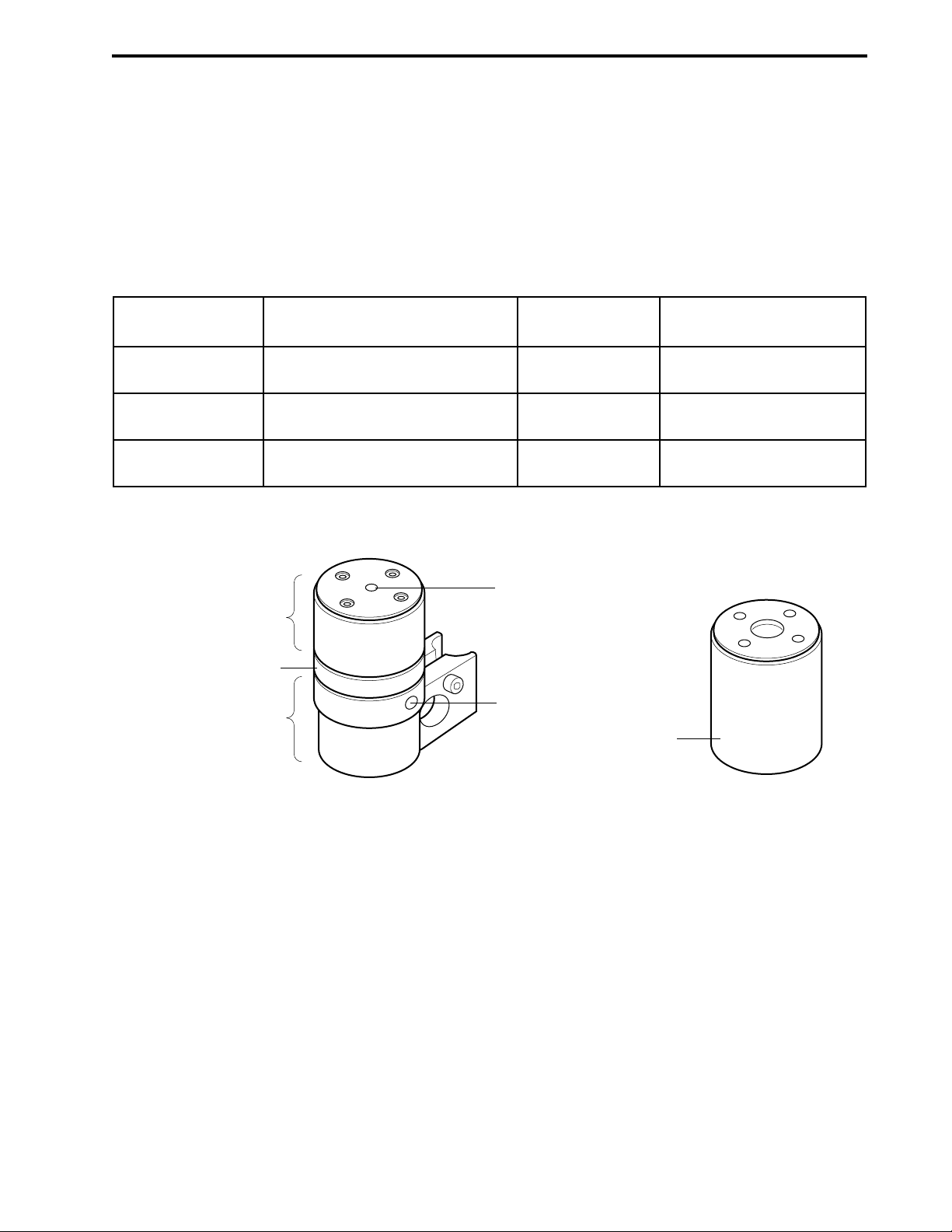
2.4.2 Maximizer Mixer
The Maximizer mixer provides the larger capacity required when the Maximizer is used. The Maximizer
mixer may be used with or without a mixer barrel: the mixer body, mixer top, and mixer barrel are provided
with the system; an optional mixer barrel extender is available. The mixer barrels fit between the mixer body
and the mixer top and are used for higher flow rates. Refer to the following table to determine the
appropriate mixer volume.
Table 2-11.
Mixer Barrels and Mixer Capacity for the Maximizer Mixer
Flow Rate Barrel Extension Capacity Assembly Screws
0.5 to 10 ml/min none 750 µl
1/4-20 x 1/2” (1.3 cm)
10 to 40 ml/min 5 ml Barrel Extender 5 ml 1/4-20 x 1 1/2” (3.8 cm)
40 to 80 ml/min 12 ml Barrel Extender 12 ml 1/4-20 x 3 1/4” (8.2 cm)
The procedure for changing the mixer capacity is provided in the following section.
Figure 2-3. Maximizer Mixer and Mixer Barrel Extender
DESCRIPTION OF BIOLOGIC DUOFLOW SYSTEMSYSTEM OVERVIEW
2-19
OUTLET PORT
MIXER
TOP
BARREL
5 ml MIXER
EXTENDER
MIXER
BODY
INLET PORT
12 ml MIXER
BARREL EXTENDER
MAXIMIZER MIXER
Page 33

2.4.3 Changing Mixer Capacity
Be sure to follow these directions carefully. The mixer may leak if it is assembled incorrectly, or if an O-ring
is not correctly placed in the O-ring groove.
Note: Flush any hazardous material from the system. Drain fluid from the mixer and disconnect the
mixer plumbing and cables.
1. If you will be changing the mixer capacity, use the information in Table 2-10 and Table 2-11 to select
the appropriate screws and barrel extension.
2. Use the hex key provided to remove the four screws from the top of the mixer (see Figure 2-4).
3. Remove the mixer top and turn it upside down to remove the O-ring. If the O-ring does not easily
dislodge, use your fingers to remove it.
4. Refer to Figure 2-4 for re-assembling the mixer. Make sure that the magnetic stir bar lies flat. If the
standard mixer barrel is to be used, assure the O-ring groove faces up.
5. Place an O-ring in each O-ring groove. If you are using only the mixer body, only one O-ring is
required. If the mixer barrel is used, two O-rings are required.
Figure 2-4. Assembly of Mixers
DESCRIPTION OF BIOLOGIC DUOFLOW SYSTEM SYSTEM OVERVIEW
2-20
SCREWS
12 ml MIXER
BARREL
MIXER
TOP
MIXER
BODY
SCREWS
OUTLET PORT
O-RING
O-RING GROOVE
5 ml MIXER
BARREL EXTENDER
O-RING GROOVE
MAGNETIC
STIR BAR
INLET PORT
MIXER
TOP
MIXER
BODY
OUTLET PORT
O-RING
O-RING GROOVE
750 µl MIXER
BARREL
EXTENDER
O-RING
O-RING GROOVE
MAGNETIC
STIR BAR
INLET PORT
ASSEMBLY OF THE MAXIMIZER MIXER
ASSEMBLY OF THE MX-1 MIXER
Page 34

2.5 DETECTION SYSTEMS
The DuoFlow system supports the following detection and monitoring devices:
• UV Detector
• Conductivity Monitor
• QuadTec UV/VIS Detector
• pH Monitor
2.5.1 UV Detector
The UV detector is a single beam, fixed wavelength UV absorbance detector specifically designed for high
resolution protein chromatography.
• Available in several configurations.
• Rack mountable and portable, which enables it to be positioned close to a column outlet for better
resolution and decreased peak band broadening.
• Optional 214 nm filter and zinc lamp available for sensitive peptide analysis.
Figure 2-5. UV Detector, with Mercury Lamp, 254 & 280 nm Filters, and Conductivity Flow Cell
The UV detector consists of the optics bench, a filter tray, a flow cell, and a lamp. It is designed to hold the
Conductivity monitor flow cell. The following configurations are available:
• Mercury Lamp and Filters. The mercury lamp comes installed in the optics module along with 280
nm and 254 nm filters. The filters are both held by a single tray. To switch filters, rotate the filter
holder. Filters for different wavelengths are also available from Bio-Rad. These include 365 nm, 405
nm, 436 nm, and 546 nm filters.
• Zinc Lamp and 214 nm Filter. The zinc lamp and 214 nm filter are optional. The zinc lamp attaches
directly to the optics module in place of the mercury lamp. (Refer to Figure 2-6)
DESCRIPTION OF BIOLOGIC DUOFLOW SYSTEMSYSTEM OVERVIEW
2-21
Page 35

Two flow cells are available with the detector. Both use 1/4-28 flat-bottom fittings.
• Analytical 5 mm flow cell. This flow cell is recommended for high resolution detection. This flow cell
has a 5 mm path length, a volume of 16 µl, and is rated to 750 psi at flow rates between 0.1 and 10
ml/min.
To reduce the risk of an entrapped air bubble causing an unstable baseline, the 5 mm flow cell
should be used with the backpressure regulator (see page 2-52). Connect the backpressure
regulator after the Conductivity monitor in the system plumbing.
• Preparative 2 mm flow cell. This flow cell is recommended for most applications which demand less
sensitivity, for flow rates greater than 10 ml/min, or when working with high protein concentrations. It
has a 2 mm path length, a volume of 30 µl, and is rated to 750 psi.
The UV detector receives power via the Workstation, to which it is connected by the UV lamp cable. The UV
detector communicates with the system via the UV optics cable, which plugs into the UV optics connector on
the back of the Workstation.
The UV detector sensitivity ranges from 0 to 2.0 AUFS (Absorbance Units Full Scale). The UV sensitivity
range for the chart recorder is set in the system software in either the Manual or Run screens. A Zero
Baseline button is available in the Manual and Run screens and a programmable Zero Baseline command is
available as part of a method protocol. Refer to the discussion of the chart recorder for setting the chart
recorder range, page 2-55.
To replace an expired lamp, refer to Chapter 11, Maintenance, or to the instruction sheet for the replacement
lamp.
Figure 2-6. UV Detector, with Zinc Lamp, 214 nm Filter, and Conductivity Flow Cell
To change the UV flow cell or UV filter:
If the system has been used, make sure that any hazardous material has been flushed from the system
and the pumps are not running. Drain fluid from the UV detector and disconnect its plumbing and
cables.
1. To remove the UV flow cell, loosen the flow cell thumbscrews and lift the flow cell out.
2. To insert a flow cell, place it into the UV detector and tighten the thumbscrews.
3. To change the UV filter, loosen the flow cell thumbscrews and lift the filter tray out.
4. Rotate the filter tray to use the correct filter, and then place it into the UV detector and tighten the
thumbscrews.
DESCRIPTION OF BIOLOGIC DUOFLOW SYSTEM SYSTEM OVERVIEW
2-22
Page 36

2.5.2 Conductivity Monitor
The Conductivity monitor, included with all DuoFlow systems, measures fluid conductivity to track the
accuracy of a salt gradient. This data is useful for optimizing purification protocols and column cleaning
procedures. Conductivity monitor sensitivity ranges from 0 to 500 mS/cm. The Conductivity monitor consists
of the following:
• Flow cell with Inlet/Outlet ports: To connect the tubing, use 1/4-28 flat bottom fittings. The flow cell
allows flow in either direction. The flow cell can be plumbed immediately after the UV flow cell or at any
other point in the flowpath. It is designed to fit into a receptacle on the UV detector (see Figure 2-7).
The volume in the cell is a nominal 6 µl.
• Signal cable: To connect to the back of the Workstation. Electrical power for the Conductivity monitor is
drawn from the signal cable. If a Maximizer is in use, connect to its COND port.
Figure 2-7. Conductivity Monitor
The Conductivity monitor can be calibrated by either entering the cell constant or by calibrating the cell
against a known standard. The Conductivity Flow Cell Constant Calibration feature is found under the
Utilities drop-down menu. The cell constant can be found on the tag attached to the cable.
The Conductivity sensitivity range for the chart recorder is set in the system software Manual and Run
screens. When setting the range, choose one that will accommodate the maximum conductivity expected
during the chromatography run. Keep in mind that although the chart recorder range can be manipulated
during a chromatography run, the data will be stored unattenuated, allowing for re-scaling at a later time.
2.5.3 QuadTec UV/VIS Detector
The BioLogic QuadTec UV/Vis detector enables four wavelengths to be monitored simultaneously and
displayed on the DuoFlow Controller. The QuadTec detector has a wavelength range of 190-370 nm using
the deuterium lamp and 370-740 nm with the halogen lamp. The deuterium lamp is standard and is required
for the detection of peptides, proteins, and nucleic acids. Both lamps are pre-aligned, calibrated, and userserviceable.
Wavelengths are selected through the use of a moveable grating monochromator with an accuracy of +/- 1
nm in 1 nm steps. When using the deuterium lamp for the monitoring of wavelengths >380 nm, an automatic
cutoff filter is activated. Because very little light of wavelengths greater than 400 nm is emitted from a
deuterium lamp, the halogen lamp is required for routine detection above 380 nm.
The QuadTec includes the following:
• 3mm Peek Flow Cell (1 µl flow cell volume, 4 µl including flow cell inlet and outlet tubes)
• 10-32 Fingertight fittings (quantity 4)
DESCRIPTION OF BIOLOGIC DUOFLOW SYSTEMSYSTEM OVERVIEW
2-23
CONDUCTIVITY MONITOR
CONDUCTIVITY FLOW CELL CONNECTOR
ON REAR OF WORKSTATION
FLOW CELL
SIGNAL CABLE TO
Page 37

• System Cable 25, RS232. To connect to the Instrument Control Module (ICM). If a Maximizer is in
use, connect to its COM1 port instead of the ICM.
• Power cord
An optional 2 mm PEEK flow cell (2.2 µl flow cell volume, 18 µl including flow cell inlet and outlet tubes) is
available for flow rates up to 80 ml/min including 10-32 long Fingertight fittings (quantity 4).
Figure 2-8. QuadTec UV/Vis Detector
For a complete discussion of the QuadTec detector, refer to its separate documentation.
DESCRIPTION OF BIOLOGIC DUOFLOW SYSTEM SYSTEM OVERVIEW
2-24
Load
Prog
Edit Prog
Link
Clear O
Events: 2
off 0 on /
Time
(min)
Signal 1
[ au ]
Signal 2
[ au ]
1
(nm)
Setup
GLP
2
(nm)
ARROW KEYS
AUTO ZERO KEY
SCAN KEY
View
Hold 0
Run 1
AUTO
ZERO
12345
SCAN
67890
FLOW PATH PORT
3
0
NUMERIC KEYS
FLOW PATH PORT
FLOW CELL
SLIDES
Page 38

2.5.4 pH Monitor
The BioLogic DuoFlow pH monitor enables direct monitoring of pH conditions during a run. The pH monitor
is optional for all DuoFlow systems.
The pH monitor consists of the following:
• Flow cell: The PEEK flow cell has a swept volume of approximately 80 µl when the pH electrode is
inserted. The flow cell mounts to the BioLogic rack using an attached mounting bracket, which can
also be used to attach the UV detector and Conductivity monitor. The flow cell should be positioned
so that the flow path is angled upward to promote bubble clearance. Plumb the flow cell with the
inlet tube attached to the lower port and the outlet tube attached to the upper port. The inlet and
outlet ports are threaded for use with 1/16” (1.6 mm) OD tubing and 1/4-28 flat bottom fittings. The
pH monitor is designed for flow rates up to 80 ml/min and flow cell pressure less than 75 psi, and
therefore should be plumbed downstream of the backpressure regulator.
• pH electrode: The pH probe is a sealed Calomel type electrode consisting of a pH and a reference
electrode built into the same body. The sealed reference design eliminates the need to add
electrolyte solutions and minimizes reference dryout. The Calomel electrode is fully compatible with
buffers (such as Tris) that may not be compatible with the Ag/AgCl (silver/silver chloride) containing
electrodes.
• Signal Cable: To connect the pH probe to the BNC connector of a Signal Import Module or
Maximizer.
Figure 2-9. pH Monitor
The pH electrode and flow cell are described in detail in their separate documentation.
2.5.5 Other Detectors
Detectors other than those offered by Bio-Rad may be used when connected to the Signal Import Module
(SIM.) Refer to Section 2.9.6.
DESCRIPTION OF BIOLOGIC DUOFLOW SYSTEMSYSTEM OVERVIEW
2-25
SIGNAL CABLE
pH ELECTRODE
pH FLOW CELL
Page 39

2.6 VALVES
BioRad offers an extensive variety of valves that enable greater flexibility for multiple sample and advanced
application options. The DuoFlow system controls 3 AVR high pressure valves and 3 SV low pressure
valves. DuoFlow systems with a Maximizer double the number of valves to 6 AVR high pressure and 6 SV
low pressure valves. Methods that include automated injection, buffer selection, column switching, and large
volume fraction collection are easily performed using various valve configurations.
For further discussion of valving applications and protocols, refer to Chapters 8-9.
2.6.1 AVR7-3 Sample Inject Valve
The AVR7-3 sample inject valve is a 7-port, 3-position valve for injecting samples and is an essential
component of all DuoFlow systems. It is rated to 3500 psi (233 bar) and is designed with non-metallic
wetted parts and minimal internal dead volume. Some features of this valve include:
• Patented make-before-break design (MBB
TM
) prevents pressure spikes when the valve rotates from
one port to another, eliminating baseline interferences and prevents pump shutdowns due to
transient over pressure situations. This is especially beneficial when using more fragile low pressure
columns or flow sensitive detectors (e.g. refractive index).
• Applications include sample injection, reverse flow chromatography and two-column switching.
• A valve rebuild kit is available.
Figure 2-10. AVR7-3 Sample Inject Valve
DESCRIPTION OF BIOLOGIC DUOFLOW SYSTEM SYSTEM OVERVIEW
2-26
A
e
v
l
A
GRADIENT
PUMP
5
4
COLUMN
3
SAMPLE
LOOP
a
V
u
n
t
o
o
i
t
S
c
e
e
l
6
WASTE
5
7
4
1
3
2
SAMPLE
WASTE
LOOP
SAMPLE
INJECT
Page 40
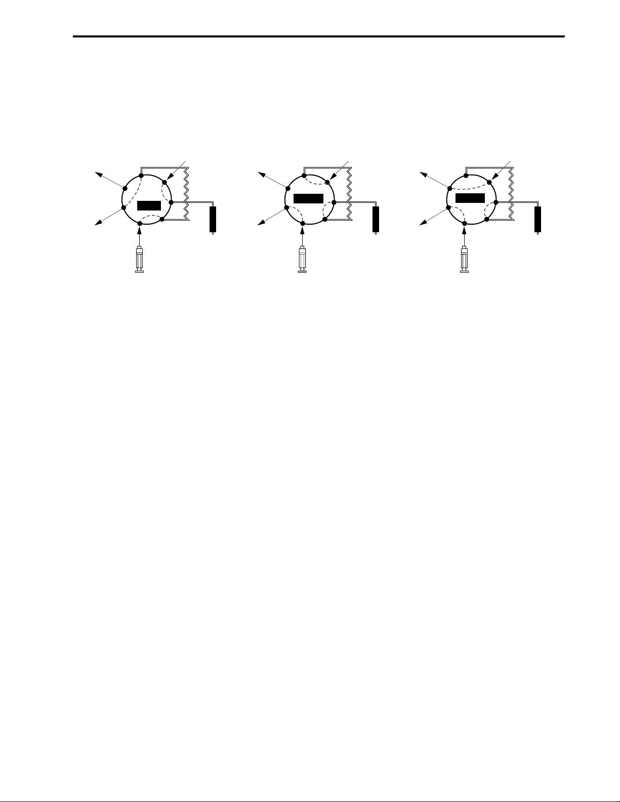
The three valve positions are Load (position 1), Inject (position 2), and Purge (position 3). See Figure 2-11.
Load is the default position when the system is powered up or at the end of a method run unless configured
differently from the Edit User Preferences window, available from the Options menu in the system software.
Figure 2-11. Sample Load Positions
The valve uses 1/16” (1.6 mm) OD tubing and 1/4-28 fittings. Sample loop sizes are available from 50 µl
loop (in the Starter kit included with all systems) to a maximum of 5 ml PEEK loop. Larger volume injections
may be obtained using Dynaloops, additional valves and/or an auxiliary pump.
Connect the AVR7-3 valve signal cable to any of the available Automated Valve connectors on the back of
the Workstation (ports 4, 5, or 6). If a Maximizer is in use connect to ports 7, 8, or 9 before those on the
Workstation. If more than 3 valves are desired, you may connect additional. valves to ports 4, 5, and 6 on
the Workstation. All valves will be active.
DESCRIPTION OF BIOLOGIC DUOFLOW SYSTEMSYSTEM OVERVIEW
2-27
WASTE
WASTE
7
1
SAMPLE
INJECT
6
LOAD
2
WORKSTATION
PUMP
5
4
COLUMN
3
SAMPLE
LOOP
WASTE
7
1
WASTE
SAMPLE
INJECT
6
INJECT
2
WORKSTATION
PUMP
5
4
COLUMN
3
SAMPLE
LOOP
WASTE
WASTE
7
1
SAMPLE
INJECT
6
PURGE
2
WORKSTATION
PUMP
5
4
COLUMN
3
SAMPLE
LOOP
Page 41
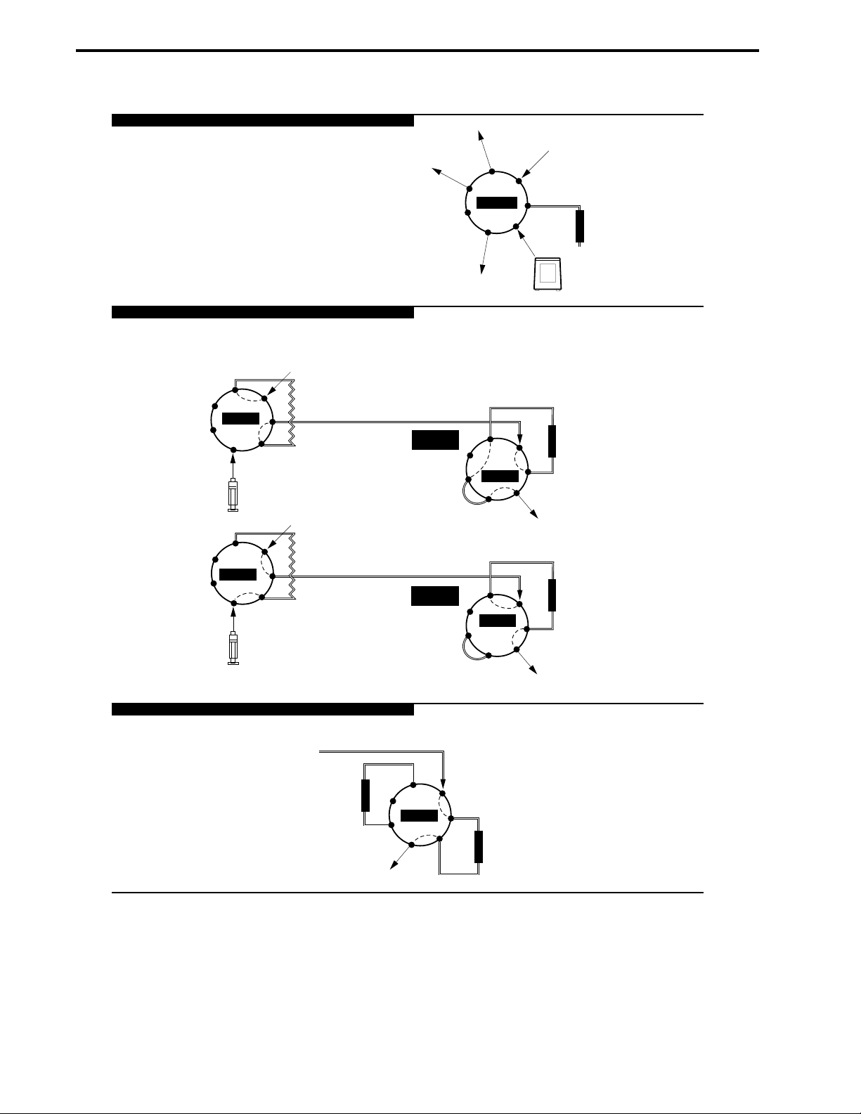
Figure 2-12. Examples of AVR7-3 Valve Tubing
DESCRIPTION OF BIOLOGIC DUOFLOW SYSTEM SYSTEM OVERVIEW
2-28
LARGE VOLUME SAMPLE LOADING
SAMPLE LOADING AND AFFINITY CHROMATOGRAPHY
AVR7-3 VALVE FOR SAMPLE LOADING
WORKSTATION
PUMP
6
5
7
1
SAMPLE
INJECT
2
4
3
SAMPLE
LOOP
INJECT
WORKSTATION
PUMP
6
5
7
1
SAMPLE
LOAD
2
4
3
SAMPLE
LOOP
INJECT
COLUMN SWITCHING
AVR7-3 AS COLUMN SWITCHING VALVE
SAMPLE LOADING
6
AVR7-3
2
WORKSTATION
PUMP
5
4
3
WASTE
WASTE
7
1
AUX
PUMP
PURGE
AUX PUMP
AVR7-3 VALVE AS "CHANGE FLOW" VALVE
FORWARD
FLOW
6
7
1
LOAD
COLUMN
5
4
3
2
UV MONITOR & FRACTION COLLECTOR
REVERSE
FLOW
6
7
INJECT
1
COLUMN
5
4
3
2
UV MONITOR & FRACTION COLLECTOR
LOW
PRESSURE
COLUMN
COLUMN #2
6
7
1
2
LOAD
5
4
3
COLUMN #1
UV/CONDUCTIVITY FLOW CELLS
Page 42

2.6.2 AVR9-8 Stream Select Valve
The AVR9-8 stream select valve is an 9-port 8-position valve. This valve is optional for all DuoFlow systems.
The valve is rated at 3500 psi (233 bar) and is designed with non-metallic wetted parts for bio-compatibility
and minimal internal dead volumes.
• The AVR9-8 is ideal for stream selection, column switching, and large volume fraction collection.
• The AVR9-8 stream select valve uses a patented make-before-break design (MBB) that prevents
pressure spikes when the valve rotates from one port to another, eliminating baseline interferences,
and prevents pump shutdowns due to transient over pressure situations. This is especially beneficial
when using more fragile low pressure columns or flow sensitive detectors (e.g. refractive index).
• A valve rebuild kit is available.
Figure 2-13. AVR9-8 Stream Select Valve
The valve’s use dictates its plumbing. For example:
• When two AVR9-8 valves are used as a column switching valve, up to eight columns may be run
sequentially.
• An AVR9-8 expands the number of available buffers or solvents when used as an Inlet Valve.
• When used in conjunction with an auxiliary peristaltic pump (such as the Bio-Rad Model EP-1 Econo
pump or EGP Econo Gradient Pump) for loop filling and an AVR7-3 inject valve, the AVR9-8 valve
may be used to select up to eight samples for consecutive chromatography runs.
DESCRIPTION OF BIOLOGIC DUOFLOW SYSTEMSYSTEM OVERVIEW
2-29
A
e
v
l
A
a
V
u
n
t
o
o
i
t
S
c
e
e
l
6
7
5
COMMON
4
1
3
2
Page 43

Position 1 on the AVR9-8 is the default position when the system is powered up or at the end of a
method run unless configured differently from the Edit User Preferences window, available from the
Options menu.
The valve uses 1/4-28 fittings and 1/16” (1.6 mm) OD PEEK tubing supplied with the fitting kit
when plumbing these valves.
Connect the AVR9-8 valve signal cable to any of the available automated valve connectors on the
back of the Workstation (ports 4, 5, or 6). If a Maximizer is in use connect to ports 7, 8, or 9 before
those on the Workstation. If more than three valves are desired, you may connect additional valves
to ports 4, 5, and 6 on the Workstation. All valves will be active.
Figure 2-14. Two Examples Using AVR9-8 Valves
DESCRIPTION OF BIOLOGIC DUOFLOW SYSTEM SYSTEM OVERVIEW
2-30
AVR7-3 INJECT VALVE FOR SAMPLE APPLICATION
WORKSTATION
WASTE
WASTE
1
RINSE
SAMPLE #1
SAMPLE #2
AVR9-8 FOR LOADING MULTIPLE SAMPLES
2
3
1
8
4
6
7
INJECT
2
PUMP
7
9
5
SAMPLE #3
AUX
6
5
4
3
SAMPLE
LOOP
PUMP
COLUMN
UP TO 8
DIFFERENT
COLUMNS
TWO AVR9-8 VALVES FOR
COLUMN SWITCHING
5
4
3
2
5
4
3
2
UV MONITOR &
FRACTION COLLECTOR
6
9
7
8
1
6
9
7
8
1
COLUMN INLET
AVR9-8 AS COLUMN
SWITCHING VALVE
TO RECEIVE SAMPLE
COLUMN OUTLET
SECOND AVR9-8 AS
COLUMN SWITCHING VALVE
TO DIRECT ELUENT,
TO MONITORS AND
FRACTION COLLECTOR
Page 44
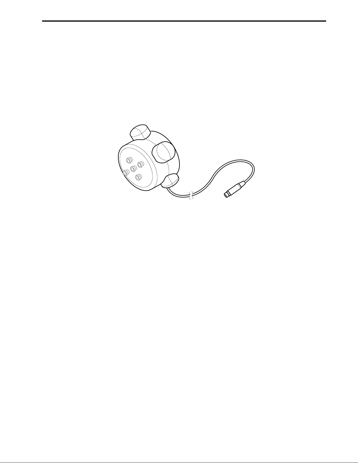
2.6.3 SV5-4 Buffer Select and Automated Sample Loading Valve
The SV5-4 valve is a low pressure, 5-port, 4-position valve used for automatic buffer selection and sample
loading. The SV5-4 valve may be used for:
• Buffer and/or sample selection when placed before the Workstation pumps or an auxilary load
pump. An SV5-4 valve connected to a Workstation pump inlet enables access to four separate
solutions.
• Fraction collection when placed after the column.
• Purging or rinsing all tubing lines for cleaning purposes.
Figure 2-15. SV5-4 Buffer Select Valve
When loading samples directly through the Workstation pump, first filter the sample through a 0.45 µm
filter. Flush the valve pump and lines with a sanitizing solution to remove protein residues after the
sample has been loaded; protein residues might otherwise reduce pump piston seal lifetime.
Connect the SV5-4 valve cable to any of the available solenoid valve connectors on the back of the
Workstation (ports 1, 2, or 3). If a Maximizer is in use, connect to ports 4, 5, or 6 before those on the
Workstation.
From the Manual screen you may manually operate each inlet port on the SV5-4. Manual valve control is
useful for the following:
• When priming the tubing and the valves with buffer and or sample prior to starting a method.
• For purging all tubing lines for cleaning purposes.
Prior to programming a method in the Protocol screen, you may name each of the valves positions in the
Setup screen. The name that you apply in the Setup screen will appear in the method Protocol screen when
you program an Isocratic Flow, Change Valve, or Linear Gradient step.
DESCRIPTION OF BIOLOGIC DUOFLOW SYSTEMSYSTEM OVERVIEW
2-31
1
2
COMMON
3
Use 1/8” (3.2 mm) OD PTFE tubing and 1/4-28 fittings when plumbing the SV5-4 valve to the Workstation
pump inlet.
To prevent air from entering the system, unused ports should be closed with 1/4-28 plugs.
Page 45
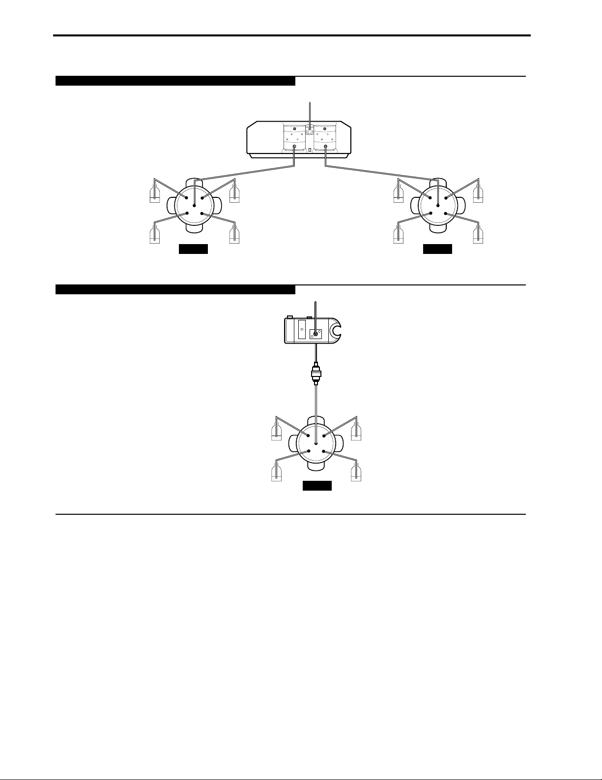
Figure 2-16. Two Examples using SV5-4 Valves
DESCRIPTION OF BIOLOGIC DUOFLOW SYSTEM SYSTEM OVERVIEW
2-32
SV5-4 FOR BUFFER AND SAMPLE LOADING
TO COLUMN
WORKSTATION
A B
RUNNING
BUFFER
STORAGE SOLUTION
(I.E., 20% ETHANOL)
SV5-4 AS FRACTION COLLECTOR
SV5-4 SV5-4
SAMPLE LOADING
& BUFFER SELECT VALVE
UV MONITOR
FRACTION
COLLECTION
FRACTION
COLLECTION
SAMPLE
SANITIZING SOLUTION
(I.E., 1M SODIUM
HYDROXIDE)
SV5-4
FRACTION COLLECTION
RUNNING
BUFFER
RUNNING
BUFFER
CONDUCTIVITY
FLOW CELL
FRACTION
COLLECTION
WASTE
RUNNING
BUFFER
RUNNING
BUFFER
BUFFER SELECT VALVE
Page 46

2.6.4 SVT3-2 Diverter Valve
The SVT3-2 diverter valve is a low pressure 3-port, 2-position valve. This valve may be used in a number of
ways:
• To divert the eluant stream from the detectors to a fraction collector or a waste container.
• As a sample select valve when placed before Workstation pump A.
The Maximizer may not be used in this application.
• As a water rinse valve when placed before Workstation pump B.
• As a user-define valve when included as part of the plumbing setup.
Figure 2-17. SVT3-2 Diverter Valve
Connect the SVT3-2 valve’s signal cable to any of the available solenoid valve connectors on the back of
the Workstation (ports 1, 2 or 3).
Plumbing connections depend on the valve’s use:
• Plumbing as a diverter valve: Use 1/16” (1.6 mm) OD PEEK tubing and 1/4-28 fittings. Use orange
PEEK 0.020” (0.51 mm) ID tubing for the F10 pumps, and green PEEK 0.030” (0.76 mm) ID tubing
for the F40 pumps.
• Plumbing before a pump: Use 1/8” (3.2 mm) OD tubing and 1/4-28 fittings.
From the Manual screen you can manually switch inlet ports on the SVT3-2. Manual valve control is useful
for the following:
• When priming the tubing and the valves with buffer prior to starting a method.
• For purging or rinsing all tubing lines during cleaning process.
In the Setup screen you can name each of the two valve positions. For example, when the SVT3-2 is placed
before the Workstation pump, you can identify the valve by the name or composition of the buffer. The name
that you apply in the Setup screen will appear in the method Protocol screen when you program an Isocratic
Flow step, a Change Valve step, or a Linear Gradient step.
When used as a diverter valve with a Model 2110 or generic fraction collector, this valve should be named
as such in the Setup screen. Position 1 of this valve is Waste; position 2, Collect.
DESCRIPTION OF SYSTEM COMPONENTSSYSTEM OVERVIEW
2-33
Page 47

Figure 2-18. Two Configurations of the SVT3-2 Valve
When used as a diverter valve with a Model 2110 or generic fraction collector, this valve should be named
as such from the Setup screen. Position 1 of this valve is Waste; position 2, Collect.
DESCRIPTION OF SYSTEM COMPONENTS SYSTEM OVERVIEW
2-34
WORKSTATION
UV MONITOR
SAMPLE SELECT
VALVE
A B
A
SAMPLE
B
WATER
RINSE
WATER RINSE
VALVE
WASTE
OR GENERIC FRACTION COLLECTOR
CONDUCTIVITY
FLOW CELL
DIVERTER
VALVE
COLLECT TO MODEL 2110
Page 48

2.7 FRACTION COLLECTORS
The DuoFlow features several options for fraction collection:
• BioFrac fraction collector
• Model 2110 fraction collector
• Model 2128 fraction collector
• Non-Bio-rad fraction collectors
The BioFrac fraction collector, the Model 2110 fraction collector, and the Model 2128 fraction collector are
programmable and can be run via BioLogic software version 4.0 or higher.
2.7.1 BioFrac Fraction Collector
The BioFrac functions with the BioLogic DuoFlow system and as a stand-alone fraction collector with the
BioLogic HR and non Bio-Rad chromatography systems. It is suited for both analytical and preparative
applications.
Figure 2-19. BioFrac Fraction Collector
Features of the BioFrac include:
• It can be used with any chromatography system at flow rates up to 100 ml/min.
• It can collect in time, drop or volume mode (time and drop mode are only available in stand-alone
mode).
• A diverter valve, mounted on either side of the vertical bars, diverts unwanted eluant to waste.
• Can be fitted with an optional drop former (25 µl drops) designed for collecting small sample sizes.
DESCRIPTION OF SYSTEM COMPONENTSSYSTEM OVERVIEW
2-35
BioFrac Fraction Collector
1
2
F1
F2
F3
F4
F5
3
4
5
6
7
8
9
0
COLLECT WASTE
COMMON
Page 49

• The BioFrac collects fractions in a serpentine pattern for all racks but may be changed to a row or
column pattern for microplates and microtiter tubes. Fourteen collection choices are possible with a
total of nine racks. The BioFrac accommodates 12-20 mm and 30 mm tube diameters, microtubes,
and scintillation vials in a variety of diameters. The optional ice bath/microplate rack allows collection
into 13 mm diameter tubes, microplates, and microtiter tubes that meet SBS standards required for
automated microplate systems. The drop head height can be adjusted to accomodate tubes up to
150 mm.
The following racks are available.
Table 2-12.
BioFrac Racks Available
Rack Name Description Capacity (Format)
F1 12-13 mm diameter tube; 2 racks (6x15), 180 tubes
150 mm height
F2 15-16 mm diameter tube; 2 racks (5x12), 120 tubes
150 mm height
F3 18-20 mm diameter tube; 2 racks (4x10), 80 tubes
150 mm height
H1 1.5-2.0 ml capless microtubes 4 racks (6x7), 168 tubes
H2 0.5 ml capless microtubes 4 racks (7x9), 120 tubes
H3 16 mm scintillation vials 4 racks (5x6), 120 tubes
H4 30 mm scintillation vials 4 racks (2x3), 24 vials
H4-High 30 mm tubes 4 racks (2x3), 24 tubes
Ice Bath, Ice bath for 13 mm diameter 1 rack (10x12), 120 tubes
Microplate rack tubes, standard microplate or 4 plates (12x8), 96 wells
microtiter tubes (SBS standard 4 plates (8x6), 48 wells
format) 4 plates (4x6), 24 wells
4 plates (3x4) 12 wells
Prep-20 Preparative rack bottle size fractions (20 funnels)
The BioFrac communicates with the DuoFlow Controller via the Instrument Bus. To connect the BioFrac to
the bitbus use either of the instrument bus connectors on the rear of the fraction collector. The BioFrac
fraction collector supports collection schemes such as Collect All, Threshold, Collection Windows, and
Threshold + Collection Windows (all with Delay volume, if required). The BioFrac diverter valve can be
mounted on either side of the fraction collector’s upright supports. See Section 3.8.1 for more information on
connecting the BioFrac to the DuoFlow system.
The BioFrac is plumbed to the DuoFlow system using 0.020” diameter PEEK tubing and 1/4-28 fittings for
flow rates up to 20 ml/min or with 0.030” diameter PEEK tubing and 1/4-28 fittings for flow rates up to
100 ml/min.
This instrument is described in detail in its separate documentation.
DESCRIPTION OF SYSTEM COMPONENTS SYSTEM OVERVIEW
2-36
Page 50

2.7.2 Model 2110 Fraction Collector
The Model 2110 is programmed in the DuoFlow software and can function as a stand-alone fraction collector
with non Bio-Rad systems. It uses a stationary, drop-dispensing head and collects up to 80 fractions in a
motor-driven carousel. It also uses standard 13 x 100 test tubes. An optional adapter is available for use
with 1.5 ml microcentrifuge test tubes. The Model 2110 includes the following features:
• In stand-alone mode the Model 2110 accepts small chromatography columns that can mount directly
to the drop-former to minimize dead volume.
• It can collect from 1 drop (50 µl) to 9 ml fraction in the 13 x 100 test tubes or 1.5 ml micro test
tubes.
• It is coldroom compatible.
Figure 2-20. Model 2110 Fraction Collector with Optional Dust Cover
The Model 2110 is connected to the Maximizer or Workstation with system cable 5, bare wires to DB-9 via
the AUX connector, black wire to pin 5 and white wire to pin 9. To prevent shorting, cut or tape wires not in
use. If a Maximizer is being used, the Model 2110 should be connected to it rather than to the Workstation.
The Model 2110 is plumbed to the DuoFlow system using 1/16” (1.6 mm) OD inlet tubing connecting directly
to the fraction collector’s drop former, without the need for additional fittings.
The SVT3-2 diverter valve is required by the Model 2110 for collection schemes other than “Collect All.”
When this valve is configured as the fraction collector diverter valve in the Setup screen, additional
collection parameters (Collect All, Threshold, Collection Windows, and Threshold + Collection Windows)
become available in the Protocol screen.
When controlled by the DuoFlow system, fraction collection is specified by volume. The fraction collection
scheme is programmed in the Protocol screen of the software where a Delay Volume feature is standard
(see Chapter 7 for discussion of Delay Volume.)
Note: Collection by drop count is not available with the DuoFlow system.
This instrument is described in detail in its separate documentation.
DESCRIPTION OF SYSTEM COMPONENTSSYSTEM OVERVIEW
2-37
MODEL 2110 FRACTION COLLECTOR
Page 51

2.7.3 Model 2128 Fraction Collector
The Model 2128 provides X/Y motion drop-dispensing across 5 available racks which accommodate a wide
range of tube diameters and lengths, microtiter plates, microtubes, and “bottle size” fractions. It is suited for
both analytical and preparative applications.
Figure 2-21. Model 2128 Fraction Collector
The following racks are available.
Table 2-13.
Model 2128 Racks Available
Rack Name Tube Description Capacity
(Software ID
Number)
Rack #1 (1) 12 and 13 mm diameter; 128 (16 X 8) tubes
180 mm height (max.)
Rack #2 (2) 16 to 18 mm diameter; 78 (13 X 6) tubes
180 mm height (max.)
Micro-Adapter (3) Microplate 3 plates (288 wells)
(96 wells in 8 X 12 format)
Micro-Adapter (4) Microtubes 128 microtubes
(capless tubes required)
Prep-Adapter (5) Bottles of any size 10 bottles
DESCRIPTION OF SYSTEM COMPONENTS SYSTEM OVERVIEW
2-38
MODEL 212
FRA
8
CTION COLLECTOR
Threshold
Next tube 2
Draining
ADV COLL STOP
7
8
9
4
5
6
1
2
HELP
3
CE
0
.
Page 52

The Model 2128 is controlled by the DuoFlow Controller via the Instrument Bus. See Chapter 3.8.3 for
connection instructions.
The Model 2128 is plumbed to the DuoFlow system using 1/16” (1.6 mm) OD inlet tubing and either of the
following fittings:
• To connect directly to the dispenser head, use 1/4-28 flat bottom fittings.
• To connect to the optional on-arm diverter valve, use the 10-32 nut and ferrule fittings supplied with
the valve.
When the Model 2128 is configured in the Setup screen, collection schemes such as Collect All, Threshold,
Collection Windows, and Threshold + Collection Windows (all with Delay volume, if required) automatically
become available in the Protocol screen. The starting and ending tube numbers also may be specified. The
Model 2128’s optional diverter valve mounts on the fraction collector’s arm and minimizes liquid spills during
fraction advances. If this valve is used, it is automatically sensed by the system and hence is not configured
by the user in the Setup screen.
This instrument is described in detail in its separate documentation.
2.7.4 Generic Fraction Collectors
A non-Bio-Rad collector may be used as an integral part of the DuoFlow system providing its tube advance
function can be initiated by an active low TTL signal (>100 ms). Electrical connection from the collector is to
pin 5 (Frac Advance) and pin 9 (ground) of the Workstation’s AUX connector. See the pin-out information in
your collector manual.
With an optional SVT3-2 diverter valve configured as a fraction collector diverter valve in the Setup screen,
the DuoFlow Controller will control all collection parameters including advanced features such as collection
by Threshold and/or Collection Windows. If the optional valve is not used, then only Collect All is available.
Fraction advance marks to a Bio-Rad chart recorder are embedded on the UV signal from the Workstation.
DESCRIPTION OF SYSTEM COMPONENTSSYSTEM OVERVIEW
2-39
Page 53

2.8 SAMPLE LOADING OPTIONS
The BioLogic DuoFlow system supports several methods for sample loading. Typically a sample is loaded
through a static fixed volume loop on the AVR7-3 inject valve. When large volume sample injections are
required, the following options are available:
• Sample loading through the Workstation pumps: The SV5-4, SV3-2 or AVR9-8 valve may be used to
load large sample volumes through the Workstation pumps. Refer to Sections 2.62 through 2.64 for
the discussion of these valves.
• Sample loading through a DynaLoop sliding-piston loop: When used with an AVR7-3 inject valve, the
DynaLoop may be used for large volume sample loading or repetitive injections of smaller volumes
of sample. The DynaLoop comes in two sizes: 25 and 90 ml volume.
• Sample loading through an auxiliary pump, such as the EP-1 Econo pump (EP-1) or the Econo
Gradient Pump (EGP). When used with an AVR7-3 inject valve, an EP-1 or EGP pump may be used
for large volume sample injections. Placing an SV5-4 or AVR9-8 valve before the pump inlet allows
loading of multiple samples.
2.8.1 DynaLoop Large Volume Sample Injection Loop
The DynaLoop, available in 25 ml and 90 ml sizes, is a sliding-piston dynamic loop for injection of a large
sample volume or repetitive injections of smaller samples. The DynaLoop has a sliding piston that functions
like a syringe. The loop is installed on the AVR7-3 in place of the static loop (see Figure 2-23). Sample is
loaded into the DynaLoop’s sample end connector through port #2 on the AVR7-3 valve and may be loaded
with a syringe or auxiliary pumps (such as the Bio-Rad Econo Gradient Pump or EP-1 pump). The loading of
the sample pushes the DynaLoop’s sliding seal towards the buffer end connector. As solution flows into the
buffer end of the DynaLoop it pushes the sample into the system.
Figure 2-22. DynaLoop
DESCRIPTION OF SYSTEM COMPONENTS SYSTEM OVERVIEW
2-40
SAMPLE END
PORT 6 ON AVR 7-3
SLIDING SEAL
ASSEMBLY
0 5 10 15 20 25
30 35 40 45 50 55 60 65 70 75 80 85 90
0 5 10 15 20 25
BUFFER END
PORT 3 ON AVR 7-3
Page 54

Figure 2-24. Plumbing the DynaLoop for use with an Inject Valve
When plumbed directly to the AVR7-3 inject valve, the DynaLoop functions just like a static sample loop. The
sample end of the DynaLoop should be plumbed to port 3 and the buffer end to port 6 of the inject valve.
The valve’s operation and sample loading are controlled automatically, simplifying the sample injection
process and insuring precise sample loading and gradient formation. The DynaLoop can be filled using a
syringe or auxiliary pump.
Use a 1/4x28 to female Luer adapter between the sample load syringe and the AVR7-3 valve port 2 makes
filling the loop much easier.
Consult the DynaLoop user's manual for additional information.
DESCRIPTION OF SYSTEM COMPONENTSSYSTEM OVERVIEW
2-41
WORKSTATION
PUMP
WASTE
LOOP
OVERFILL
TO WASTE
6
2
5
4
3
COLUMN
LOAD PUMP
7
AVR7-3
1
SYRINGE OR AUXILIARY
DYNALOOP
Page 55

2.8.2 Model EP-1 Econo Pump
The Model EP-1 Econo pump is a two-channel, bi-directional, variable speed peristaltic pump for lowpressure chromatography. The EP-1 offers a full range of features to facilitate ease of use as a stand-alone
pump or as an accessory to the DuoFlow System to load large volumes onto low pressure columns. This
instrument is described in detail in its separate documentation. Features of the EP-1 include:
• The EP-1 has preset calibration for common tubing sizes and manual calibration for nonstandard
size tubing.
• It controls various fraction collectors, including the BioFrac, Model 2110, and Model 2128 fraction
collectors.
• It can control the run length with a programmable total run volume.
• It is coldroom compatible.
Figure 2-24. Model EP-1 Econo Pump
The EP-1 Econo pump is ideal for loading samples onto a low-pressure column. When using a low-pressure
column, such as an Econo-Pac cartridge, remove the 40 psi backpressure regulator from the post-column
position. Place it at the outlet of the Workstation pump. This will allow the check valves to properly seat and
ensure pump flow performance.
The EP-1 Econo pump must contain firmware version 2.12 or higher to function with the BioLogic DuoFlow
system. To confirm the firmware version, simultaneously press and hold down the Direction key and the
down arrow key on the front panel of the EP-1 Econo pump. If the Econo pump does not have the correct
firmware version, contact BioRad for information on how to upgrade the pump.
The EP-1 Econo pump receives start/stop signals only. The flow rate of the EP-1 Econo pump is set from
the pump, and the flow rate is recorded in the yellow data entry boxes of the Load/Inject Sample dialog box.
The DuoFlow system starts/stops the Aux pump and cannot control the flow of the EP-1 Econo pump. The
correct flow rate must be set at the EP-1 Econo pump.
Consult the EP-1 Econo pump user's manual for additional information.
DESCRIPTION OF SYSTEM COMPONENTS SYSTEM OVERVIEW
2-42
ECONO PUMP
ml
min
ml/min
%
0.8
1.6
3.2
CAL
V
o
V
t
Page 56

2.8.3 EGP Econo Gradient Pump
The Econo Gradient Pump (EGP) is a two-channel, bi-directional, variable speed peristaltic pump for lowpressure chromatography and general laboratory use. The EGP has the following features:
• The EGP can be programmed to run a gradient.
• The EGP controls a splitter valve for stream splitting.
• The EGP may be used with most flexible tubing having an inner diameter less than or equal to 3.2
mm (1/8”), and a wall thickness of 1.0 mm or less, including Silicone, Tygon, and PharMed.
• Flow rates are 0.01-20 ml/min per channel, depending upon tubing ID.
• It has start/stop control of fraction collectors and chart recorders.
• It is coldroom compatible.
Figure 2-25. EGP Econo Gradient Pump
Consult the Econo gradient pump user manual for additional information.
DESCRIPTION OF SYSTEM COMPONENTSSYSTEM OVERVIEW
2-43
Platen
ECONO GRADIENT PUMP
RunPurge
Next
Cancel
Step
Arrow Keys
Reverse
Remote
Setup
Manual
Program
Mode
LCD Display
Soft Keys
Page 57

2.8.4 Other Gradient Pumps
The BioLogic DuoFlow system sends a TTL signal to control an external pump. This signal is normally TTL
high (5 volts). The DuoFlow system commands the external pump to run by holding Pin 4 "low". Any pump
accepting this signal may be used with the DuoFlow system as a sample loading pump. Refer to your
pump’s separate documentation when connecting the pump to the DuoFlow system.
DESCRIPTION OF SYSTEM COMPONENTS SYSTEM OVERVIEW
2-44
Page 58

2.9 SYSTEM PERIPHERALS
A number of system peripherals are available for use with DuoFlow systems. The following system
peripherals are discussed in this section:
• System rack
• Starter kit
• Fittings kit
• Fittings tightener
• Backpressure regulator
• SIM
• F10 and F40 Pump kits
• Chart recorders, including the Model 1327 chart recorder
• Uninterruptable power supply (UPS)
• Printers
2.9.1 System Rack
The BioLogic rack is an adaptable and durable racking system made of solvent-resistant polypropylene,
stainless steel, and glass-filled nylon. The rack can stand alone or be placed directly on the Workstation and
supports various columns and cartridges, valves, detection modules, buffer bottles, and peripheral
equipment.
The rack should be assembled before placing it on the Workstation as described below (see Figure 2-26).
Keep in mind that the illustration is only an example. Alternative rack arrangements include mounting the
column clamps on the side of the rack to hold tall columns or setting up the rack to use only one or two
trays.
1. Fit the tapered collars into the ringed grooves on the rods. The collars are tapered so that when they
are attached to the rods and the rods are fitted into the holes at each end of the tray, the rods and
collars serve as the legs of the tray. With this in mind, note the following guidelines:
• For a 2 or 3-tray rack, you will need four long rods; for a 1-tray rack you will need just two long
rods. The long rods have three grooves, one at each end and one in the middle. Attach the
collars to one of the end grooves. It doesn’t matter which of the end grooves you use. Attach the
collars so that they flare out toward the end of the rod that will be placed at the bottom of the
rack.
• For a one tray rack, use the two short rods which have only one groove. Fit the collars onto the
grooves so that the collars flare out toward the end of the rod that will be placed at the bottom of
the rack.
DESCRIPTION OF SYSTEM COMPONENTSSYSTEM OVERVIEW
2-45
Page 59
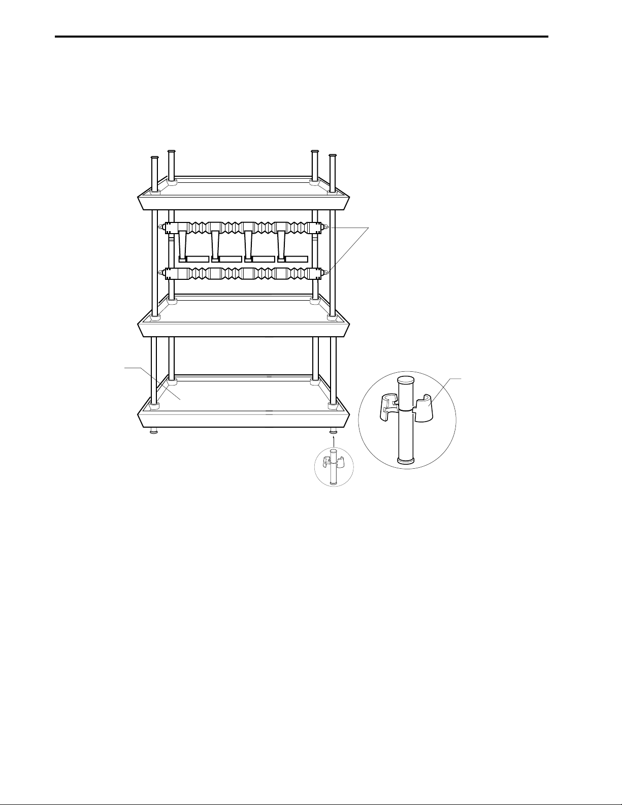
2. Insert the rods into the holes at each corner of a tray. Insert the rods from underneath the tray such
that they produce a firm fit in the holes.
3. For a 2 or 3-tray rack, attach sleeves to the middle of all four long vertical bars. Remember that the
sleeves should be oriented so that the wide part of the taper is nearest the rod’s bottom end.
Figure 2-26. Rack Assembly
4. For a 2 or 3-tray rack, place the second tray on top of the four sleeves and press firmly to seat the
tray. Repeat these instructions to add the upper tray.
5. Mount the 2-piece column clamping arrangement across the two long rods using the attached
thumbscrews.
6. Two horizontal bars with rod clamps and an Allen wrench are provided with the system. These are
used to hold devices, such as valves. Position them between any of the upright bars.
7. Remove the four green caps covering the holes at the four corners on top of the Workstation. Place
the rack into the four corner holes.
DESCRIPTION OF SYSTEM COMPONENTS SYSTEM OVERVIEW
2-46
COLUMN
CLAMPING
ARRANGEMENT
TRAY
TAPERED
COLLAR
Page 60

DESCRIPTION OF SYSTEM COMPONENTSSYSTEM OVERVIEW
2-47
2.9.2 Starter Kit
The Starter kit is included with each DuoFlow system. The kit includes step-by-step instructions for
programming and running a separation of a premixed anion exchange standard containing equine
myoglobin, conalbumin, chicken ovalbumin, and soybean trypsin inhibitor, using a 1.3 ml UNO Q1 Column.
The Starter kit includes the following items for running a separation:
• 50 ml of Buffer A, 250 mM Tris buffer pH 8.1 (10 X concentrate)
• 50 ml of Buffer B, 250 mM Tris buffer pH 8.1 plus 5.0 M NaCl (10 X concentrate)
• One vial of Anion Exchange Protein Standards (catalog number 125-0561)
• One 1-ml disposable sample injection syringe
• One 50 µl sample loop
• 50 ml of Maximizer solution A1 (10x concentrate)
• 50 ml of Maximizer solution A2 (10x concentrate)
• 50 ml of Maximizer solution B2 (2.5x concentrate)
The UNO Q1 Column (catalog number 720-0001) is not included with the Starter kit but is included with
each DuoFlow system.
For a complete discussion of the Starter kit, refer to its separate documentation.
2.9.3 Fittings kit, including Tubing kit
The DuoFlow Fittings kit is included with all DuoFlow system. It contains the following components:
• PEEK and PTFE Tubing
• Tefzel Plugs, Adaptors, Unions, and Caps
• Tubing Cutter
• 3 ml Syringe and 10 ml Luer Slip Syringe
• Molded Bottle Caps
• BioLogic Fittings Tool
• Screwdriver
• PEEK F to M and F to F Luers
• Delrin Nuts
• Super Flangeless Ferrules
• F10 Tubing Kit
Optional tubing kits include the following:
• F10 Tubing Kit
The F10 Tubing Kit includes precut 1/4-28 fitted PTFE, Tefzel, and 0.02” ID PEEK tubing for easy
installation of a DuoFlow basic systems. An installation chart indicates suggested placement of each
piece of labeled tubing (see Section 4.0).
The kit includes: a length of PTFE tubing, 1/8” OD, for connecting solution bottles to the Workstation
pumps A and B; a length of Tefzel tubing, 1/16” OD, for connecting AVR7-3 waste lines; and 8
additional pieces of PEEK, orange, 1/16” OD x 0.02” ID tubing, to connect the pump, mixer, column,
detector, and other components.
Page 61

• F40 Tubing kit
The F40 Tubing kit is identical to the F10 kit (described previously), however, all orange PEEK
tubing is replaced with PEEK, green, 1/16” OD x 0.03” ID tubing. The large bore tubing is designed
for use with the higher flow rates when using the Maximizer or F40 Workstation pumps.
• Maximizer Tubing kit
Inlet A1 uses red tubing and is used for acid solutions. Inlet A2 uses blue tubing and is used for
base solutions. Inlet B1 uses yellow tubing and is used for water solutions. Inlet B2 uses green
tubing and is used for salt solutions.
The kit includes an installation chart.
• Maximizer Interconnect Tubing kit
This kit contains cut and fitted tubing to connect the Workstation pumps A and B inlets to the
Maximizer valves A and B outlets. There are two preformed PEEK 1/8” OD sets of tubing in this kit.
• pH Montior Tubing kit
The pH monitor includes cut and fitted tubing to connect the pH flow cell to the Conductivity flow
cell. There is a length of PEEK, orange, 1/16” OD x 0.02” ID tubing rated to 5000 psi and a length of
PEEK, green, 1/16” OD x 0.03” ID tubing rated to 3000 psi for higher flow rates.
2.9.4 Fittings Tightener
The fittings tightener is designed to apply appropriate tightness to the nut, stainless steel lock ring, and the
ferrule, when installing 1/4-28 fittings on the end of tubing. The flattened end of the lock ring should face
towards the nut with the tapered end facing the tapered end of the brown ferrule. Place the tubing and
fittings into the green fittings tightener. Do not allow the tubing to slip out of the ferrule. Tighten the fitting to
seat the ferrule onto the tubing, but do not over-tighten. Once the fitting is made, it can be inserted into the
port. Refer to instructions on next page.
Figure 2-27. Making 1/4-28 Flat Bottom Fittings
DESCRIPTION OF SYSTEM COMPONENTS SYSTEM OVERVIEW
2-48
The tubing kit that accompanies the Maximizer for connecting the reagent bottles to the valves is
composed of FEP PTFE, 1/8” OD x 0.062” ID. Each length of tubing is color coded to identify its
connection
site and solution.
FITTINGS TIGHTENER
PEEK FERRULE
STAINLESS STEEL
COMPRESSION RING
CUT THE
TUBING
TUBING
FITTINGS
TIGHTENER
NUT
Page 62

The following procedure describes ferrule installation.
1. Slide the nut, stainless steel compression ring and the ferrule, in that order, onto the tubing as
shown at left. The flattened end of the ring should face the nut. The tapered end of the ferrule
should face the ring.
2. Allow tubing to extend slightly beyond the end of the ferrule.
3. Place the fitting into the green fittings tightener. Do not allow the tubing to slip out of the ferrule.
4. Insert the tubing and fitting into the fittings tool to tighten to seat the ferrule onto the tubing, do not
overtighten.
2.9.5 Backpressure Regulator
The 40 psi backpressure regulator is used with flow rates below 10 ml/min. Plumb the backpressure
regulator following the direction of the arrow.
The Backpressure Regulator helps eliminate bubble formation within the detector. As a solution is pumped
through a column, the column exerts a backpressure that serves to keep any air bubbles in solution.
Solution exiting the column returns to atmospheric pressure and air bubbles may form. As the bubbles pass
through, or lodge in the detector flow cell they may cause artifacts on the baseline chromatogram that
appear as spikes. This “outgassing” may be minimized by thoroughly degassing buffers and by placing a
backpressure regulator after the Conductivity monitor. The backpressure from the regulator helps to keep
the bubbles in solution.
When using low pressure columns such as an Econo-Pac® cartridge, plumb the 40 psi backpressure
regulator between the Workstation pump outlet and the mixer. This aids in seating the check valves,
preventing permanent damage to the cartridge or column.
Figure 2-28. Backpressure Regulator
DESCRIPTION OF SYSTEM COMPONENTSSYSTEM OVERVIEW
2-49
Page 63

2.9.6 Signal Import Module (SIM)
The Signal Import Module digitizes an analog signal and transmits it to the DuoFlow Controller. It is used to
import signals from non Bio-Rad detectors into the DuoFlow software.
• The SIM allows for connection of any pH probe and detector that outputs an analog signal between
-2.5 Volts to +2.5 Volts. Instruments that may be connected in this way could include a variable
wavelength UV detector, a refractive index detector, or a fluorescence detector.
• Two SIMs may be connected to a DuoFlow system.
Figure 2-29. Signal Import Module (front and rear views)
The output from a pH electrode is connected to the pH connector (a BNC connector) on the SIM; the output
from any other detector is connected at the 3-pin connector (+, -, gnd) of the SIM. The Automatic
Temperature Compensation (ATC) connector is reserved for future upgrades and enhancements.
The instrument bus cable connects the SIM to the USB Bitbus Communicator. (Refer to Figures 2-29 and
2-30.) If a second SIM is to be used, one of the instrument bus cables is used to connect the two SIMs. The
SIM is described in detail in its separate documentation. When a SIM is connected to the instrument bus,
the USB Bitbus device must be connected to an external powersource (see Section 2.1.2).
Figure 2-30. Cable Connections to the Signal Import Module
DESCRIPTION OF SYSTEM COMPONENTS SYSTEM OVERVIEW
2-50
IN(+) IN(-) GND
ANALOG ATC pH
INSTRUMENT BUS POWER/
DEVICE
NUMBER
STATUS
CONNECTING A SINGLE SIM
INSTRUMENT BUS POWER/
TO USB BITBUS
COMMUNICATOR
DEVICE
NUMBER
STATUS
CONNECTION TO THE
FOLLOWING DEVICES
(LISTED IN SEQUENCE):
• MAXIMIZER (IF AVAILABLE)
• WORKSTATION
TO USB BITBUS
COMMUNICATOR
CONNECTING TWO SIMs
INSTRUMENT BUS POWER/
DEVICE
NUMBER
STATUS
INSTRUMENT BUS POWER/
DEVICE
NUMBER
STATUS
TO WORKSTATION
Page 64

2.9.7 Pump Kits
The Workstation pumps are easily converted to either a F10 or F40 pumphead to expand functional pump
flow rates as indicated in the table below.
Table 2-14.
Workstation Pump Configuaration Flow Rates
Workstation Pump Flow Rate Flow Rate with Maximizer
F10 0.01-10 ml/min 0.5-20 ml/min
F40 0.5-40 ml/min 1.0-80 ml/min
There are two kits, the F10 Pump kit and the F40 Pump kit. Each kit contains fully assembled pumpheads
with seals and check valves installed.
The F10 Pump kit contains the following items:
• Two F10 pumpheads assembled with check valves, seals, and O-rings
• Four F10 piston assemblies
• Installation instructions
PEEK tubing, orange, 1/6” OD x 0.02 ID is supplied in the Fittings kit of the DuoFlow system
The F40 Pump kit contains the following items:
• Two F40 pumpheads assembled with check valves, seals, and O-rings
• Four F40 piston assemblies
• One 2 ml mixer barrel extender
• Two mixer O-rings
• One 2mm UV flow cell
• PEEK tubing, green, 1/16” OD x 0.03” ID (rated to 3000 psi)
• Installation instructions
For a complete discussion of the Pump kits, refer to the separate documentation supplied with the kits.
DESCRIPTION OF SYSTEM COMPONENTSSYSTEM OVERVIEW
2-51
Page 65

2.9.8 Model 1327 Chart Recorder
The Model 1327 chart recorder is a dual-pen chart recorder that is compatible with many detection devices.
The chart recorder includes the following features:
• Two-channel, dual-pen capability.
• Compact in size (31 x 23 x 7.6 cm).
• Voltage ranges from 1 mV to 20V.
• Twelve chart speeds for recording methods.
Figure 2-31. Model 1327 Chart Recorder
The DuoFlow Controller outputs the UV analog data signal, pen up/down, and Stop/Start commands to the
Model 1327 chart recorder via the Workstation’s UV Chart connector (cabled to the chart recorder using
System Cable 2 mini DIN to standard DIN). The Conductivity analog data signal is sent from the
Workstation’s Conductivity Chart (Cond Chart) connector to channel 2 of the chart recorder using System
Cable 4 (mini-DIN to banana plugs). The chart recorder should be set to all green settings (1V). The chart
recorder is described in detail in its separate documentation.
Note: The chart speed is set at the recorder. The BioLogic DuoFlow does not control this function.
Event marks are recorded on the chart recorder for the following:
• Fraction Collector Advance: When the fraction collector advances to the next tube.
• A manual event mark from the Run screen. Pressing the Event Mark button on the Run screen
allows you to “mark” events as they happen.
Non-Bio-Rad UV detectors: If the Model 1327 chart recorder is used in conjunction with a SIM and a thirdparty detector to replace the DuoFlow UV Detector, System Cable 20 should be used to control the
recorder. Channel 1 signals should be sent directly from the third-party detector using a bare wires-tobanana plug cable. In this case, the appropriate input voltage range must be selected on the recorder. Refer
to the documentation for your non-Bio-Rad UV detector.
2.9.9 Generic Chart Recorders
A non-Bio-Rad chart recorder may be used as an integral part of the DuoFlow system. If the DuoFlow
system’s UV detector is used, a mini-DIN to breakout cable (System Cable 7) must connect the
Workstation’s UV Chart connector to the chart recorder. Pen Up/Down and Start/Stop functions are available
providing the control polarity of the generic recorder is compatible. See the pin-out information in your chart
recorder manual.
Conductivity signals require a Bio-Rad mini-DIN to banana plug cable (System Cable 4).
Set the chart recorder’s input signal voltage to 1 V for both BioLogic DuoFlow UV detector and Conductivity
monitor signals. Chart speed is set at the recorder itself, it is not controlled by the DuoFlow system.
DESCRIPTION OF SYSTEM COMPONENTS SYSTEM OVERVIEW
2-52
Page 66

2.9.10 Uninterruptible Power Supply (UPS)
A UPS may be required in laboratory environments that experience power outages or where the quality of
power varies. Bio-Rad can supply a UPS in both 110 V and 220 V configurations. For questions about this
UPS, consult your local Bio-Rad representative.
2.9.11 Printers
Any Windows
®
2000 compatible printer may be used with the DuoFlow systems. The printer must include a
connection cable and a printer driver.
To install a printer driver, exit the DuoFlow software. If the printer driver disk is available, follow the
instructions that are included with that disk. If the printer driver disk is not available, click on the Windows
®
Start button and from Settings, select Control Panel.
In the Control Panel, double-click on the Printers icon to open the Printers window. Then double-click on the
Add Printer icon and follow the on-line instructions. If your printer does not appear in the list of printers
available, contact the printer manufacturer for a recommendation on which driver to use.
DESCRIPTION OF SYSTEM COMPONENTSSYSTEM OVERVIEW
2-53
Page 67

2.10 COLUMNS AND COLUMN FITTINGS
Bio-Rad offers a variety of column chemistries and formats. The following pages provide a summary of the
different column types and column fittings for use with BioLogic DuoFlow systems. Bio-Rad columns for the
DuoFlow use the following matrices:
• UNO
TM
columns use the new Continuous Bed matrix which contains an advanced polymer matrix
that is completely homogeneous. These columns are superior to beaded supports in resolution,
binding capacity, speed, and value.
• Bio-Scale chemistries are based on 10 µm Macro-Prep
®
supports. They are offered in various sizes
and allow for scale-up separation and purification. These medium-pressure columns are ideally
suited for use on the DuoFlow system.
• The Econo-Pac cartridge chemistries are based on 50 µm Macro-Prep
®
supports and are ideal for
first step purification.
2.10.1 Anion Exchange: Q Strong Anion Exchange
The Q strong anion exchanger chemistry is available in the following formats:
• UNO Q Biochromatography Columns: These columns are designed to handle separations at high
flow rates with low back pressure. Instead of a traditional bed of packed beads or particles, each
column contains an advanced polymer matrix, called the Continuous Bed matrix, which is nonporous
and homogeneous. The matrix is designed to maximize resolution, binding capacity, and speed.
Refer to bulletins 2116 and 1946.
• Bio-Scale Q Prepacked Medium Pressure Columns: These columns are designed for high
resolution separations of proteins, peptides, and polynucleotides in analytical to semipreparative
medium pressure applications. They are available in four column sizes. Methods developed on the
Bio-Scale columns can be transferred to production scale using the Macro-Prep
®
supports. Refer to
bulletins 1880, 1946, and 2079.
• Econo-Pac High Q Low Pressure Chromatography Cartridges: These cartridges are available in
1 ml and 5 ml formats to accommodate most sample loads. They are recommended for method
scouting and for first step purification of crude samples. They are based on 50 µm Macro-Prep
®
supports. Refer to bulletin 1946.
• Macro-Prep
®
High Q Support: This is a strong anion exchanger containing quaternary amine
functional groups with a 50 µm particle size. It is ideal for rapid purification of acidic and neutral
proteins and peptides. Refer to bulletins 1840 (A-100), 1917, and 1985.
2.10.2 Cation Exchange: S Strong Cation Exchange
The S strong cation exchanger chemistry is available in the following formats:
• UNO S Biochromatography Columns: These columns are designed to handle separations at high
flow rates with low back pressure. Instead of a traditional bed of packed beads or particles, each
column contains an advanced polymer matrix, called the Continuous Bed matrix, which is nonporous
and homogeneous. The matrix is designed to maximize resolution, binding capacity, and speed.
Refer to bulletins 2116 and 1946.
• Bio-Scale S Pre-packed Medium Pressure Columns: These columns are designed for high
resolution separations of proteins, peptides, and polynucleotides in analytical to semipreparative
medium pressure applications. They are available in four column sizes. Methods developed on the
Bio-Scale columns can be transferred to production scale using the Macro-Prep
®
50 µm supports.
Refer to bulletins 1881, 1946, and 2079.
DESCRIPTION OF SYSTEM COMPONENTS SYSTEM OVERVIEW
2-54
Page 68

• Econo-Pac High S Low Pressure Chromatography Cartridges: These cartridges are available in
1 ml and 5 ml formats to accommodate most sample loads. They are recommended for method
scouting and for first step purification of crude samples. They are based on 50 µm Macro-Prep
®
supports. Refer to bulletin 1985.
• Macro-Prep
®
High S Support: This is a strong cation exchanger containing sulfonic acid functional
groups with a 50 µm particle size. It is ideal for purification of basic and neutral proteins and
peptides. Refer to bulletins 1840 (A-200), 1917, and 2079.
2.10.3 Anion Exchange: DEAE Weak Anion Exchange
The DEAE weak anion exchanger chemistry is available in the following formats:
• Bio-Scale DEAE Prepacked Medium Pressure Columns: These columns are designed for high
resolution separations of proteins, peptides, and polynucleotides in analytical to semipreparative
medium pressure applications. They are available in four column sizes. Methods developed on the
Bio-Scale columns can be transferred to production scale using the Macro-Prep
®
10 µm supports.
Refer to bulletins 1930, 1946, and 2079.
• Econo-Pac DEAE Blue Low Pressure Chromatography Cartridges: These cartridges are
available in 1 ml and 5 ml formats to accommodate most sample loads. They are recommended for
method scouting and for first step purification of crude samples. They are based on 50 µm MacroPrep
®
supports. Refer to bulletin 1946.
• Macro-Prep
®
DEAE Support: This is a weak anion exchanger containing diethylaminoethyl
functional groups with a 50 µm particle size. It is ideal for purification of acidic and neutral proteins
and peptides. Refer to bulletin 1840 (A-400).
2.10.4 Cation Exchange: Carboxy Methyl (CM) Weak Cation Exchange
The CM weak cation exchanger chemistry is available in the following formats:
• Econo-Pac CM Low Pressure Chromatography Cartridges: These cartridges are available in 1
ml and 5 ml formats to accommodate most sample loads. They are recommended for method
scouting and for first step purification of crude samples. They are based on 50 µm Macro-Prep
®
supports.
2.10.5 Ceramic Hydroxyapatite (CHT)
The CHT chemistry is available in the following formats:
• Bio-Scale CHT Type I Prepacked Medium Pressure Columns: These columns are designed for
high resolution separations of proteins, peptides, and polynucleotides in analytical to
semipreparative medium pressure applications. They are available in four column sizes. Methods
developed on the Bio-Scale columns can be transferred to production scale using the Macro-Prep
®
10 µm supports. Refer to bulletins 1929, 1946, 2079, and 2156.
• Econo-Pac CHT-II Low Pressure Chromatography Cartridges: These cartridges are available in
1 ml and 5 ml formats to accommodate most sample loads. They are recommended for method
scouting and for first step purification of crude samples. They are based on 20 µm Macro-Prep
®
supports. Refer to bulletin 1946.
DESCRIPTION OF SYSTEM COMPONENTSSYSTEM OVERVIEW
2-55
Page 69

• Macro-Prep®CHT Support: Macro-Prep®ceramic hydroxyapatite (CHT) overcomes the physical
and chemical instability of crystalline hydroxyapatite and is available in two types. Type I has a high
protein binding capacity and better binding capacity for acidic proteins. Type II is better suited for
proteins that elute early and for nucleic acids. Refer to bulletins 1842 (C-100), 1927, 1971, and
2156.
2.10.6 Size Exclusion Chromatography (SEC)
The SEC supports are available in the following formats:
• HPLC SEC Columns: Bio-Sil and Bio-Select 5 µm silica-based columns separate compounds by
the mechanism of size exclusion. The technique is based on diffusion in and around highly porous
spherical silica beads. The columns are recommended for the separation of peptides, proteins, and
nucleic acids, for desalting or buffer exchange, and for molecular weight or molecular constant
determination. Columns are available in both stainless steel (Bio-Sil columns) and biocompatible
PEEK plastic hardware (Bio-Select columns). Each column is shipped with a free vial of Bio-Rad’s
protein standards. Refer to bulletins 1737 and 1946.
• Econo-Pac P6 Low Pressure Chromatography Cartridges: This 5 ml cartridge is used for
desalting and buffer exchange. Refer to bulletin 1946.
2.10.7 High Pressure Reversed Phase Columns
The following type of column is available:
• Hi-Pore reversed phase columns: These columns are commonly used for the purification and
analysis of small proteins (<50 kd), peptides, oligonucleotides, and amino acids. Refer to bulletin
1946.
2.10.8 Hydrophobic Interaction Chromatography (HIC)
The HIC chemistry is available in the following formats:
• Econo-Pac t-Butyl HIC Low Pressure Chromatography Cartridges: These cartridges are
available in a 5 ml format to accommodate most sample loads. They are recommended for method
scouting and for first step purification of crude samples. They are based on 50 µm Macro-Prep
®
supports. Refer to bulletins 1946 and 2079.
• Econo-Pac HIC Low Pressure Chromatography Cartridges: HIC is offered in both methyl and
t-butyl chemistries. These cartridges are available in 1 ml and 5 ml formats to accommodate most
sample loads. They are recommended for method scouting and for first step purification of crude
samples. They are based on 50 µm Macro-Prep supports. Refer to bulletin 1946.
• Macro-Prep
®
HIC Support: HIC is offered in both methyl and t-butyl chemistries. The Macro-Prep
®
methyl HIC support is ideal for purification of proteins with strongly hydrophobic regions. The
Macro-Prep
®
t-butyl HIC support is ideal for purification of proteins with few or weakly hydrophobic
regions. Refer to bulletin 1841.
DESCRIPTION OF SYSTEM COMPONENTS SYSTEM OVERVIEW
2-56
Page 70

2.10.9 Affinity Chromatography
Affinity chromatography is available in the following formats:
• Econo-Pac Protein A Low Pressure Chromatography Cartridges: These cartridges are available
in 1 ml and 5 ml formats to accommodate most sample loads. They are recommended for
monoclonal antibody purification. Refer to bulletin 1946.
• Econo-Pac Blue and DEAE Blue Low Pressure Chromatography Cartridges: These chemistries
are available in a 5 ml format and are recommended for albumin and protease removal. Refer to
bulletin 1946.
2.10.10 Empty Columns
The following columns are available:
• Bio-Scale MT empty columns: These columns allow for easy packing of a chromatographic media,
bed height adjustment, sample application, and equilibration. The availability of four column sizes
(2, 5, 10, and 20 ml) allows easy scale-up of separation and purification protocols. Request bulletin
1970.
• Glass Econo-Column columns: Econo-Column chromatography columns are the standard for high
quality, affordable low pressure chromatography columns. They accept both Econo-Column funnels
and flow adapters.
DESCRIPTION OF SYSTEM COMPONENTSSYSTEM OVERVIEW
2-57
Page 71

DESCRIPTION OF SYSTEM COMPONENTS SYSTEM OVERVIEW
2-58
2.10.11 Column Fittings
Table 2-15.
Columns and Column Fittings
Fittings Required
Catalog # 732-0113
Econo-Pac
®
Cartridge to
Fittings Kit
Catalog # 750-0565
Econo-Column
®
to
BioLogic System Fittings Kit
This kit includes all the parts
needed to connect EconoColumns and flow adapters
to the BioLogic DuoFlow
system.
Catalog # 750-0561
Union, 1/4-28 to M6
Column Type
Econo-Pac®
Cartridge
Econo-Column®/
Low Pressure
Columns and flow
adapters
FPLC® Column
Description
The Econo-Pac cartridge has one male and one
female luer-lock fitting. To connect it to the
BioLogic system use 1/4-28 to male and 1/4-28 to
female luer adapters, provided in the kit shown to
the right. One set is included in the Fittings kit.
Econo-Columns have two male luer-lock fittings.
To connect to the system, use female luer to 1/428 adapters.
If a flow adapter with flexible tubing is to be used,
attach the barbed-to-male luer fitting (included in
this kit), then connect the female luer to 1/4-28
adapter.
If the column adapter uses PTFE tubing, attach
the small length of 1/16” (1.6 mm) ID Tygon®
tubing and insert the barbed male luer fitting into
open end. Five cm of Tygon tubing is included in
this kit. Connect as above.
Pharmacia’s FPLC columns use M-6 fittings. To
connect to the system, use 1/4-28 to M6 adapter
union. Two of these are supplied with the Fittings
kit.
Page 72

Table 2-15. (continued)
Columns and Column Fittings
DESCRIPTION OF SYSTEM COMPONENTSSYSTEM OVERVIEW
2-59
Column Type
HPLC Column, or
Pharmacia’s
RESOURCE
™
Column
UNO
™
Column to
FPLC system
UNO
™
Column to
HPLC system
Description
These columns accept 10/32 nuts. To connect this
type of column to the system, use two 1/4-28 to
10-32 adapters.
This kit includes two nuts and four ferrules to
connect an UNO column to an FPLC system.
This kit includes two nuts and four ferrules to
connect an UNO column to an HPLC system.
Fittings Required
Catalog # 750-0564
HPLC Column to BioLogic
System Adapters
Catalog #750-0567
M6 Fittings Kit
Catalog #750-0568
10-32 Fittings Kit
Page 73

3.0 SYSTEM SETUP
The modular design of BioLogic DuoFlow systems permits you to arrange the system to best meet
application and space requirements. Each of the following subsections discuss how to set up the different
components. Setup of each component is the same, regardless of the system you have.
The Workstation and the Maximizer have many rear panel connectors that are identical.The conductivity
monitor must be connected to the Maximizer.
Figure 3-1. Example of a DuoFlow Pathfinder System Configuration
SYSTEM SETUPSYSTEM INSTALLATION AND SETUP
3-1
TM
UNO Q1 COLUMN
AVR7-3 SAMPLE
INJECT VALVE
MAXIMIZER MIXER
USB BITBUS COMMUNICATOR
DELL CONTROLLER
KEYBOARD
MOUSE
A B
MAXIMIZER
VALVE A VALVE B
QUADTEC DETECTOR
pH MONITOR
CONDUCTIVITY
MONITOR
WORKSTATION
BioFrac Franction Collector
F1 F2
F3 F4 F5
1 2 3
4 5 6
7 8 9
0
BIOFRAC
Page 74

The compact design of the Workstation and rack are ideal for laboratories with limited space or for systems
that must go into a cold box or cold room. For these instances the Controller can be placed away from the
Workstation (see Figure 3-2 below). Bus communication cables of lengths up to 100 feet can be purchased
from Bio-Rad, and USB cables can be purchased from any computer supply store.
Figure 3-2. DuoFlow Pathfinder Setup in Non-Condensing Environment
3.1 CONTROLLER CABLE CONNECTIONS
The Controller consists of a monitor, computer, keyboard, and mouse. Bio-Rad provides a Dell computer for
use as a Controller.
Detailed instructions for setting up your Controller are provided in the separate documentation
provided with your Controller.
1. Place the Controller so that the back side is facing you. Connect the monitor, keyboard, and mouse
to the computer.
2. Connect the power cables to the computer and monitor. If the computer has a second power outlet,
use it to plug in the monitor power cable. Do not turn on power to these devices yet.
SYSTEM SETUP SYSTEM INSTALLATION AND SETUP
3-2
LABORATORY
USB BITBUS
COMMUNICATOR
USB BUS
INSTRUMENT BUS
COLD ROOM
AB
VALVE A VALVE B
Page 75

SYSTEM SETUPSYSTEM INSTALLATION AND SETUP
3-3
3.2 USB BITBUS COMMUNICATOR CABLE CONNECTIONS
The USB Bitbus Communicator allows communication between the Controller and the rest of the DuoFlow
system. To connect the USB Bitbus Communicator:
1. Connect System Cable 31 from the USB Bitbus Communicator to the computer USB connector.
Refer to the illustration below.
2. If a Signal Import Module (SIM) is to be used with the system (see lower half of Figure 3-3).
a. Connect the USB Bitbus Communicator power adapter (catalog number 760-2034).
b. Set the Power Select switch to External.
Figure 3-3. USB Bitbus Communicator Cabling
REAR VIEW
REAR VIEW
DELL CONTROLLER
SYSTEM
CABLE 31
DELL CONTROLLER
PWR
SELECT
EXT
INT
USB BUS
PWR
SELECT
EXT
INT
REAR VIEW
INSTRUMENT BUS
SYSTEM CABLE
17, 18, 19, 21, OR 30
REAR VIEW
USB BITBUS
COMMUNICATOR
FRONT VIEW
SYSTEM CABLE
17, 18, 19, 21 OR 30
INSTRUMENT BUS
USB BITBUS
COMMUNICATOR
FRONT VIEW
CONNECTION TO THE
FOLLOWING DEVICES
(LISTED IN SEQUENCE):
MAXIMIZER (IF AVAILABLE)
WORKSTATION
SIGNAL IMPORT MODULE
REAR VIEW
CONNECTION TO THE
FOLLOWING DEVICES
(LISTED IN SEQUENCE):
SIM (IF AVAILABLE) OR
MAXIMIZER (IF AVAILABLE)
WORKSTATION
WALL AC POWER
SYSTEM
CABLE 31
USB BUS
UNIVERSAL
AC/DC INLINE ADAPTOR
Page 76
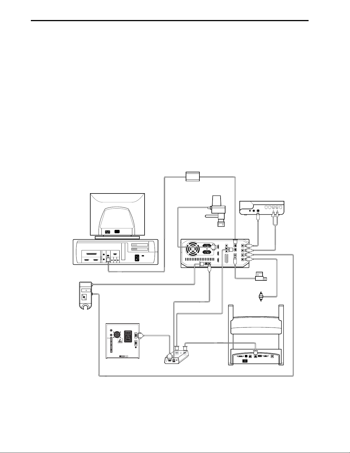
SYSTEM SETUP SYSTEM INSTALLATION AND SETUP
3-4
3.3 WORKSTATION CABLE CONNECTIONS
1. Confirm the voltage setting for the Workstation power supply. A red switch on the back of the
Workstation allows you to switch between 110 VAC and 240 VAC.
2. Connect the power cable to the Workstation. Do not turn on this device yet.
3.3.1 Systems without a Maximizer
If the Maximizer is NOT to be part of the system, follow the procedure below to connect the Workstation to
the USB Bitbus Communicator.
1. Note the two connectors marked “Instr Bus.” These connectors are identical: either may be used
when connecting bus communication cables.
2. Select a System Cable of sufficient length to reach the USB Bitbus Communicator. System Cables
17, 18, 19, 21, and 30 differ only in their lengths.
Figure 3-4. System Cable Connections (without Maximizer)
UV DETECTOR
DELL CONTROLLER
USB CABLE
SYSTEM
CABLE 25
SYSTEM
CABLE 31
USB BITBUS
COMMUNICATOR
AVR7-3
INJECT
VALVE
SYSTEM CABLE 26,
ICM POWER CORD
SYSTEM CABLE
17, 18, 19, 21, OR 30
SYSTEM CABLE
17, 18, 19, 21, OR 30
SYSTEM CABLE
17, 18, 19, 21, OR 30
WORKSTATION
MODEL 1327
CHART RECORDER
SYSTEM
CABLE 2
MX-1 MIXER
CONDUCTIVITY
MONITOR
SYSTEM
CABLE 4
QUADTEC
DETECTOR
ICM MODULE
BIOFRAC
Page 77

SYSTEM SETUPSYSTEM INSTALLATION AND SETUP
3-5
3.3.2 Systems with a Maximizer
If the Maximizer is to be part of the system, follow the procedure below to connect the Maximizer to the
Workstation and the USB Bitbus Communicator.
1. Place the Workstation on top of the Maximizer.
2. Note the two connectors marked “Instr Bus.” These connectors are identical: either may be used
when connecting instrument bus cables.
3. With the back side of the Workstation and Maximizer facing you, connect System Cable 30
between the Workstation and the Maximizer.
4. Select a System Cable of sufficient length to reach the USB Bitbus Communicator. System Cables
17, 18, 19, 21, and 30 are different only in their lengths.
5. Connect the power cable to the Maximizer. Do not turn on this device yet.
Figure 3-5. System Cable Connections (with Maximizer)
SYSTEM CABLE 30
DELL CONTROLLER
MODEL 1327
CHART RECORDER
AVR7-3
INJECT
VALVE
MAXIMIZER
MIXER
MAXIMIZER
SYSTEM
CABLE 25
SYSTEM
CABLE 31
USB BITBUS
COMMUNICATOR
CONDUCTIVITY
MONITOR
WORKSTATION
SYSTEM CABLE
17, 18, 19, 21, OR 30
UV DETECTOR
SYSTEM
CABLE 2
BIOFRAC
SYSTEM
CABLE 4
QUADTEC
DETECTOR
pH MONITOR
SYSTEM CABLE
17, 18, 19, OR 21
Page 78

SYSTEM SETUP SYSTEM INSTALLATION AND SETUP
3-6
3.4 SYSTEM RACK SETUP
Assemble the system rack before placing it on the Workstation. Detailed discussion of system rack
assembly is provided in Section 2.9.1. Keep in mind that the illustration is only an example. Alternative rack
arrangements include setting up the rack to use only one or two trays.
To mount the system rack on the Workstation, remove the four green caps covering the holes at the four
corners on top of the Workstation. Place the rack into the four corner holes.
Figure 3-6. Rack Assembly
COLUMN
CLAMPING
ARRANGEMENT
TRAY
TAPERED
COLLAR
Page 79

3.5 MIXERS
Two mixers have been designed for use with the DuoFlow system: the MX-1 mixer and the higher capacity
Maximizer mixer. The mixers are shipped pre-assembled with their mixer barrel. The mixer barrel may be
removed or replaced increasing or decreasing the internal volume to provide the mixer capacity appropriate
to the flow rate. Refer to table 3.1 when selecting a mixer volume.
Figure 3-7. Mixers
Table 3-1.
Mixer Flow Rates
Flow Rate Barrel Extension Capacity Assembly Screws
MX-1 Mixer (for use without Maximizer)
less than 1ml/min none 263 µl 10-32 x 5/8” (1.6 cm)
1 to 10 ml/min 750 µl mixer barrel extender 750 µl 10-32 x 7/8” (2.2 cm)
10 to 40 ml/min 2 ml mixer barrel extender 2 ml 10-32 x 1-1/2” (3.8 cm)
Maximizer Mixer (for use with Maximizer)
0.5 to 10 ml/min none 750 µl 1/4-20 x 1/2” (1.3 cm)
10 to 40 ml/min 5 ml mixer barrel extender 5 ml 1/4-20 x 1-1/2” (3.8 cm)
40 to 80 ml/min 12 ml mixer barrel extender 12 ml 1/4-20 x 3-1/4” (8.2 cm)
SYSTEM SETUPSYSTEM INSTALLATION AND SETUP
3-7
SCREWS
SCREWS
OUTLET PORT
MIXER
TOP
OUTLET PORT
O-RING
O-RING GROOVE
750 µl MIXER
BARREL
EXTENDER
O-RING
O-RING GROOVE
MAGNETIC
STIR BAR
INLET PORT
12 ml MIXER
BARREL
MIXER
BODY
ASSEMBLY OF THE MAXIMIZER MIXER
O-RING
O-RING GROOVE
5 ml MIXER
BARREL EXTENDER
O-RING GROOVE
MAGNETIC
STIR BAR
INLET PORT
MIXER
TOP
MIXER
BODY
ASSEMBLY OF THE MX-1 MIXER
Page 80

To attach the Mixer to the rack:
1. Confirm that the selected mixer and its capacity volume is appropriate for the flow rate. If it is not,
refer to the previous chapter for the procedure for changing the mixer capacity.
2. Attach the mixer to a vertical bar using its rod clamp. The mixer should be positioned between the
pump and the AVR7-3 inject valve. Attach the mixer to the rack so that the mixer outlet port faces
upward.
3. Connect the mixer signal cable (mini-DIN connector) to the connector marked Mixer on the rear of
the Maximizer, if available. Otherwise, connect to the Workstation. Refer to Figures 3-4 and 3-5.
4. Plug the unused inlet port using the plug provided.
SYSTEM SETUP SYSTEM INSTALLATION AND SETUP
3-8
Page 81

3.6 DETECTION SYSTEM CONNECTIONS
This section discusses how to connect the UV detector, the Conductivity monitor, the QuadTec detector, and
non-Bio-Rad UV detectors.
3.6.1 UV Detector and Conductivity Monitor
Two flow cells are available for use with the UV detector.
• Analytical 5 mm flow cell for high resolution protein chromatography applications and low flow rates.
It has a path length of 5 mm for maximum sensitivity and a volume of only 16 µl. It can be used with
flow rates from 0.1 to 10 ml/min.
• Preparative 2 mm flow cell for work not requiring high sensitivity, or when working with high protein
concentrations, and for flow rates greater than 10 ml/min. It has a path length of 2 mm and a volume
of 30 µl.
Figure 3-8. UV Detector and Conductivity Monitor
To attach the UV Detector and Conductivity Monitor to the rack:
1. Using the information provided above, confirm that the UV flow cell capacity volume is appropriate
for the flow rate. Complete discussion of the UV detector and conductivity monitor is provided in
Section 2.5, including the procedure for changing the UV flow cell.
2. Using the rod clamps, attach the UV detector to a vertical or horizontal bar close to the column
outlet.
3. Connect the power cable (square connector) from the UV detector lamp into the connector marked
UV Lamp on the rear of the Workstation. Refer to Figures 3-4 and 3-5.
4. Connect the UV detector signal cable (mini-DIN connector) to the connector marked UV Optics on
the rear of the Workstation. Refer to Figures 3-4 and 3-5.
5. Connect the Conductivity monitor’s combined power and signal cable (mini-DIN connector) to the
connector marked Cond. Flow cell on the rear of the Maximizer, if available. Otherwise, connect it
to the Workstation. Refer to Figures 3-4 and 3-5.
6. The Conductivity monitor is designed to be held in the circular notch of the optics bench, but may be
placed anywhere in the fluid path.
SYSTEM SETUPSYSTEM INSTALLATION AND SETUP
3-9
Page 82

3.6.2 QuadTec UV/Vis Detector
The QuadTec detector is shipped with a “dummy” flow cell installed. Before operating the detector, you need
to install the biocompatible 3mm PEEK flow cell. For complete discussion of the QuadTec detector, including
the procedure for installing the flow cell, refer to the QuadTec Instruction Manual.
1. Make sure the detector power is OFF.
2. Loosen the two knurled screws on the front of the flow cell and gently pull them out. This allows the
flow cell housing to slide out.
3. Remove the dummy cell by gently pulling it upward. Save the dummy cell in a secure place. It is
required for measuring signal and reference output values for the lamps. See Section 5.1, Checking
the Status of D2 Lamp, in the QuadTec instruction manual for instruction on recording signal and
reference values.
4. Insert the new flow cell and make sure that the engraved specifications point towards the user and
that the fixing hole on the back side of the cell meets the corresponding metal pin of the detector's
housing.
5. Slide the complete system towards the detector, insert the two knurled screws, and tighten them by
hand.
6. Attach the 10-32 Fingertight fittings and tubing to the inlet and outlet ports and use a syringe to rinse
the flow cell with 10-20 ml of 100% analytical grade methanol, followed by 5 ml distilled deionizied
(DDI) water.
7. Connect the QuadTec to the DuoFlow system. If the Maximizer is to be used, the QuadTec should
be connected to the Maximizer rear panel Com 1 connector using System Cable 25. If the
Maximizer is not in use, connect the QuadTec via the Instrument Control Module (ICM), as
discussed on page 3-11.
Figure 3-9. QuadTec Detector
SYSTEM SETUP SYSTEM INSTALLATION AND SETUP
3-10
Load
Prog
Edit Prog
Clear O
Events: 2
off 0 o
(min)
n /
Time
3
Hold 0
Run 1
12345
67890
1
(nm)
Signal 1
[ au ]
Signal 2
[ au ]
Setup
GLP
2
(nm)
FLOW PATH PORT
0
FLOW CELL
FLOW PATH PORT
ZERO
SCAN
Link
View
AUTO
SLIDES
FLOW CELL HOUSING
Page 83

The ICM translates the signal from the QuadTec detector and transmits it to the DuoFlow Workstation.
Figure 3-10. Instrument Control Module (ICM)
(front and rear views; for use when the Maximizer is not to be used)
The ICM contains the following:
Front View of ICM Module (required if Maximizer is not in use)
• Address setting: dial should always be set to position 1.
• Instrument bus connector: System Cable 17 connects to the Workstation and the BioFrac fraction
collector (if used). (Refer to Figures 3-4 and 3-5.)
Rear View
• Serial Comm connector: System Cable 25 (QuadTec RS232 cable), connects to the QuadTec
detector.
• Power connector: System Cable 26, connects to the DuoFlow Workstation DC outlet.
The QuadTec detector is equipped with a universal power supply, which operates with supply voltages from
90 to 260 Volts AC. A manual setting of the supply voltage is not required.
CAUTION! Make sure to use a properly grounded power outlet and the power cable provided with the
system.
To connect the QuadTec to the Workstation via the ICM module,
1. Use System Cable 25 to connect from the RS232 connector on the back of the QuadTec to the
COMM connector on the ICM module.
2. Use System Cable 26, the ICM power cord, to connect to the back of the Workstation.
3. Use System Cable 17 to connect between an instrument bus connector on the ICM and an available
instrument bus connector on the Workstation.
4. If you are using a Bio-Rad device with an instrument bus connector, such as the BioFrac fraction
collector, use another System Cable 17 to connect between the instrument bus connectors on the
BioFrac and the ICM.
SYSTEM SETUPSYSTEM INSTALLATION AND SETUP
3-11
INSTR. BUS INSTR. BUS
DEVICE
NUMBER
2
3
1
4
0
5
7
6
FRONT VIEW REAR VIEW
RX
TX
COMM
POWER
_ _ _
9...25 V
0.3A MAX
ON
Page 84

3.6.3 pH Monitor
The pH monitor, available as an option from Bio-Rad, (refer to section 2.5.4 for more information) may be
connected to the DuoFlow system in one of two ways:
• To a Workstation connect the Signal Import Module (SIM) included with the pH Monitor. The SIM
connects to the DuoFlow Workstation through the bus communication cables (System Cables 17,
18, 19, 21, or 30).
• To a Maximizer, if in use, connect to the rear BNC connector labeled pH.
Figure 3-11. pH Monitor
To connect the Bio-Rad pH electrode to the SIM,
1. Connect the output cable from the pH electrode to the connector labeled pH Connector on the SIM.
2. Connect the SIM to the USB Bitbus Communicator by using an Instrument Bus cable (System
Cables 17, 18, 19, 21, or 30), as shown below.
3. Connect an external power source to the USB Bitbus device (see Section 2.1.2).
Figure 3-12. SIM Connections
SYSTEM SETUP SYSTEM INSTALLATION AND SETUP
3-12
SIGNAL CABLE
pH ELECTRODE
pH FLOW CELL
CONTROLLER
USB BITBUS
pH
MONITOR
COMMUNICATOR
WORKSTATION
SIM
NON-BIO-RAD
UV DETECTOR
SYSTEM CABLE #20
CHART
RECORDER
BARE WIRE TO
BANANA PLUGS
FOR CHANNEL 1
Page 85

3.6.4 Non-Bio-Rad Detectors
The Signal Import Module (SIM), available from Bio-Rad, allows you to connect a variety of additional
devices such as UV, fluorescence, and RI detectors. Before connecting the detector to the SIM, consult the
documentation provided with the detector to determine the cable requirements for connecting to the 3-pin
connector (+, -, Gnd) on the SIM.
The SIM connects to the DuoFlow Workstation and Controller through the use of the Instrument Bus cables
(System Cables 17, 18, 19, 21, or 30), as shown above. Channel 1 signals are sent to the chart recorder by
connecting the UV detector to the chart recorder using bare wires to banana plugs. System Cable 20
transmits start/stop, pen up/down, and event mark signals.
SYSTEM SETUPSYSTEM INSTALLATION AND SETUP
3-13
Page 86

3.7 VALVE CONNECTIONS
The DuoFlow system is shipped with an AVR7-3 inject valve. The connection of all valves is similar, as
discussed below:
• To connect either the AVR7-3 inject valve or an AVR9-8 stream select valve, mount the valve to a
vertical bar on the system rack and connect its cable to any of the connectors labeled Automated
Valves 10, 11, or 12 on the rear of the Maximizer, if available. Otherwise, connect it to connectors 4,
5, or 6 on the Workstation.
• To connect an SVT3-2 diverter valve or the SV5-4 buffer select valve, mount the valve to a vertical
bar on the system rack and then connect its cable to any of the connectors labeled Solenoid Valves
7, 8, or 9 on the rear of the Maximizer, if available. Otherwise, connect it to connectors 1, 2, or 3 on
the Workstation.
• Refer to section 2.6 for more detailed information about each valve.
Figure 3-13. DuoFlow Valves
SYSTEM SETUP SYSTEM INSTALLATION AND SETUP
3-14
HIGH PRESSURE
A
e
v
l
a
A
V
u
n
t
o
o
i
t
S
c
e
e
l
GRADIENT
PUMP
5
6
WASTE
5
7
4
4
COLUMN
1
3
3
SAMPLE
2
SAMPLE
LOOP
WASTE
LOOP
SAMPLE
INJECT
A
e
v
l
a
A
V
u
n
t
o
o
i
t
S
c
e
e
l
6
7
5
COMMON
4
1
3
2
1
COMMON
LOW PRESSURE
2
3
AVR7-3 AVR9-8 SV5-4 SVT3-2
Page 87

3.8 FRACTION COLLECTOR CONNECTIONS
This section discusses the connections for the following instruments and devices:
• BioFrac fraction collector
• Model 2110 fraction collector
• Model 2128 fraction collector
Refer to section 2.7 for more detailed information about the fraction collectors.
3.8.1 BioFrac Fraction Collector
The BioFrac fraction collector is controlled by the DuoFlow software version 4.0 or greater via the
Instrument Bus. The BioFrac fraction collector is connected to the system as discussed below:
1. Connect the USB Bitbus to the Controller as discussed in Section 3.2.
2. Use either of the instrument bus connectors on the rear of the fraction collector to connect the
BioFrac fraction collector to the Instrument bus. (see Section 3.3)
3. Select BioFrac in the BioLogic Configuration Utility.
3.8.2 Model 2110 Fraction Collector
The Model 2110 fraction collector may be connected to the Workstation, as discussed below:
1. Connect the DB-9 connector on System Cable 5 to the Model 2110 fraction collector.
2. Connect the bare wires to the AUX connector on the Workstation as follows: Black wire to pin 5 and
white wire to pin 9.
3.8.3 Model 2128 Fraction Collector
The Model 2128 fraction collector is controlled by the DuoFlow Controller via the Instrument Bus. The
Model 2128 fraction collector is connected to the system as discussed below:
1. Connect the USB Bitbus to the Controller as discussed in section 3.2.
2. Use the instrument bus connector on the rear of the fraction collector to connect the Model 2128
fraction collector to the instrument bus. Since the Model 2128 has only one instrument bus
connector, it should be the last device "daisy-chained" to the instrument bus.
3. Select Model 2128 in the BioLogic Configuration Utility.
SYSTEM SETUPSYSTEM INSTALLATION AND SETUP
3-15
Page 88
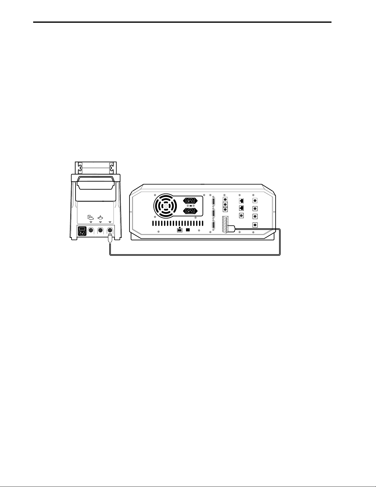
3.9 PUMP CONNECTIONS
This section discusses the connections for the following instruments and devices:
• Model EP-1 Econo pump
• Econo Gradient Pump (EGP)
3.9.1 Model EP-1 Econo Pump
The EP-1 Econo pump is connected to the system as discussed below:
To connect the EP-1 Econo pump with the DuoFlow system, make the following cable connections:
Figure 3-14. Connecting an EP-1 Econo Pump to the BioLogic DuoFlow Workstation
1. On System Cable 7 locate the red and blue wires at the wire end of the cable and connect them to
the DuoFlow Workstation.
Cut short all other wires and insulate with tape.
a. Connect the red wire to pin 6 of the Aux connector.
b. Connect the blue wire to pin 9 of the Aux connector.
2. Plug the 8-pin mini-DIN connector into the Aux connector on the rear panel of the Econo pump.
PharMed tubing is recommended for use in the pumphead of the EP-1 Econo pump. For additional
information on this pump, consult its user manual. The illustration below shows the Aux pump connected to
port 3 of the Inject Valve.
SYSTEM SETUP SYSTEM INSTALLATION AND SETUP
3-16
ECONO PUMP
REAR PANEL
WORKSTATION
REAR PANEL
4
AUX
UV LAMP
10..25V 0.3A MAX.
5
6
1
2
3
SOLENOID VALVES
1. INJECT
2. n/c
3. n/c
4. n/c
AUTOMATED VALVES
5. FC ADV
6. AUX PUMP
7. n/c
8. n/c
9. GND
INSTR. BUS
MIXER
UV
CHART
COND
CHART
UV
OPTICS
COND
FLOWCELL
RED TO PIN #6
BLUE TO PIN #9
SYSTEM CABLE 7
Page 89

Figure 3-15. Example of Direct Inject Sample Loading using an Econo Pump
The EP-1 Econo pump can be used to load up to 7 samples sequentially when used with an AVR9-8 at the
pump’s inlet valve, as shown below.
Figure 3-16. Example of Multiple Sample Loading using an Econo Pump
3.9.2 Econo Gradient Pump (EGP)
Refer to section 2.8.3 for more information. The EGP is connected to the Workstation using an Instrument
Bus communication cable (System Cables 17, 18, 19, 21, or 30). Connect its power cable to an available
outlet. Be sure to use the appropriate fuse. Refer to the separate documentation for the EGP for fuse
specifications.
The EGP is connected to the DuoFlow Workstation with Bus communication cable (System cables 17, 18,
19, or 21). When the DuoFlow assumes control of the EGP, the EGP is automatically set to Remote mode.
SYSTEM SETUPSYSTEM INSTALLATION AND SETUP
3-17
WASTE
WASTE
WASTE
7
1
2
EP-1
PUMP
PURGE
6
AVR7-3
WORKSTATION
PUMP
5
4
3
EP-1
ECONO
PUMP
LOW
PRESSURE
COLUMN
WORKSTATION
PUMP
WASTE
AVR7-3
LOOP OVERFILL
TO WASTE
6
LOAD
5
4
LOW
3
PRESSURE
COLUMN
7
1
2
EP-1 ECONO
PUMP
8
RINSE
SAMPLE #1
SAMPLE #2
1
2
3
4
7
9
5
SAMPLE #3
6
AVR9-8
Page 90

In Remote mode, the EGP keys provide limited control, allowing only basic observation of EGP operating
parameters. For a complete discussion of the EGP, refer to its separate documentation.
The illustration below shows the Aux pump connected to port 3 of the inject valve.
Figure 3-17. Example of Direct Inject Sample Loading using an Econo Gradient Pump (EGP)
The Econo Gradient Pump (EGP) can be used to load up to 7 samples sequentially when used with an
AVR9-8 at the pump’s inlet valve, as shown below. See Chapter 8 for more details.
Figure 3-18. Example of Multiple Sample Loading using an Econo Gradient Pump (EGP)
SYSTEM SETUP SYSTEM INSTALLATION AND SETUP
3-18
WASTE
WASTE
WASTE
7
AVR7-3
1
2
EGP
PUMP
PURGE
WORKSTATION
6
5
4
3
ECONO
GRADIENT
PUMP
LOW
PRESSURE
COLUMN
PUMP
WORKSTATION
PUMP
WASTE
AVR7-3
LOOP OVERFILL
TO WASTE
6
LOAD
5
4
LOW
3
PRESSURE
COLUMN
7
1
2
ECONO GRADIENT
PUMP (EGP)
8
RINSE
SAMPLE #1
SAMPLE #2
1
2
3
4
7
9
5
SAMPLE #3
6
AVR9-8
Page 91

3.10 MODEL 1327 CHART RECORDER CONNECTIONS
The Model 1327 chart recorder is optional. It may be positioned on the rack shelf or on the bench.
1. Connect System Cable 2 between the Workstation and the recorder as follows:
a. The mini-DIN connector is connected to the connector marked “UV Chart” on the rear of the
Workstation. Refer to Figures 3-4 and 3-5.
b. The DIN connector is connected to the single DIN connector on the side of the chart recorder.
This cable provides system control of pen up/down, event marks and paper advance, but chart
speed MUST be set on the recorder faceplate itself.
2. Conductivity signals are recorded on channel 2 of the recorder using System Cable 4 as follows:
a. The mini-DIN connector is connected to the connector marked “Cond. Chart” on the rear of the
Workstation. Refer to Figures 3-4 and 3-5.
b. The banana plugs are connected to the connectors marked CH 2 on the side of the recorder
(red wire to +, black wire to ground | ).
3. Set both channel inputs on the recorder to 1V. Set all other switches to their position marked in
green. Connect the power adapter to the chart recorder.
3.11 COMPLETING SYSTEM SETUP
Once you have completed the system setup, turn the units around. Connect the USB cable to the USB
Bitbus communicator and connect the instrument bus cables. Plug in the power cords, and turn on the
system. In certain laboratory environments, an uninterruptable power supply (UPS) may be required. BioRad offers both 110 V and 220 V UPS configurations; consult your local Bio-Rad representative.
3.11.1 DuoFlow System Network Connections
The DuoFlow system can be connected to an Ethernet network, allowing you to print reports and export files
over the network. Refer to the documentation provided with your PC computer for details on cable
connection and software setup. Contact your site administrator to ensure proper communication and access
with the existing network.
3.11.2 System Power Up
Power up the system. The following is intended as a checklist of instruments and devices that may be
connected to the system. The sequence is not important, although it is best to power on the Controller last.
1. Turn on power to the DuoFlow Workstation.
2. Turn on power to the Maximizer, if in use.
3. Turn on power to the following devices and instruments, if they are available:
a. Power up the QuadTec using the power switch on the rear of the detector.
The QuadTec detector goes through a startup routine, self-test, and lamp calibration routine.
b. Power up the auxiliary pump. Auxiliary pumps include the EP-1 Econo pump and the Econo
Gradient Pump (EGP).
c. Power up the fraction collector. Fraction collectors include the BioFrac, the Model 2110, and the
Model 2128.
4. Power up the Controller. At this point, the DuoFlow software application may be launched.
5. When the DuoFlow Controller establishes communication with the system, the faceplate in the
Manual screen and the status bar at the bottom of the screen show which devices and instruments
are connected and communicating with the system. The system is ready for operation.
SYSTEM SETUPSYSTEM INSTALLATION AND SETUP
3-19
Page 92
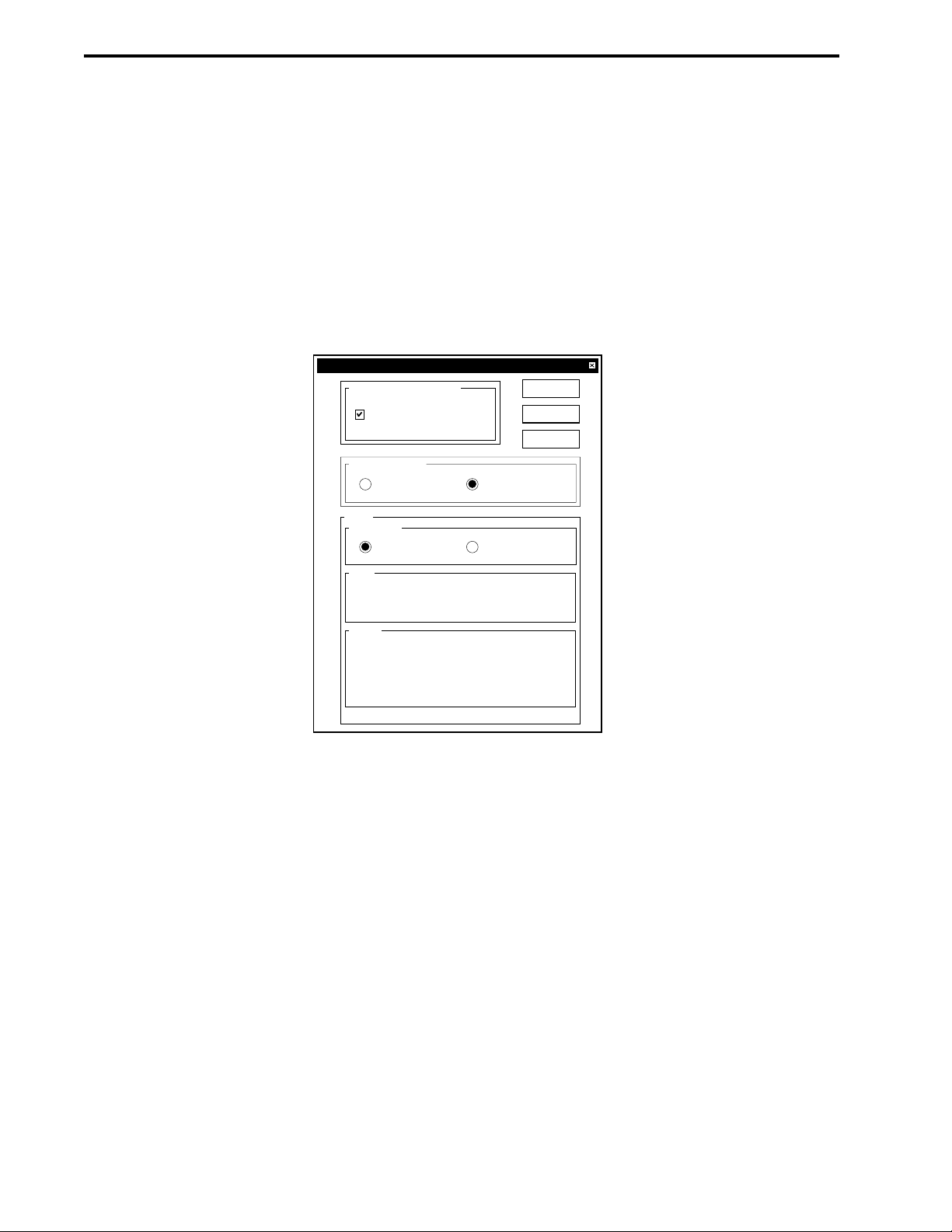
3.11.3 BioLogic Configuration Utility Software
The BioLogic Configuration utility is used anytime the pumpheads are changed or a Maximizer is installed. It
is also used to choose between Bio-Rad’s BioFrac and Model 2128 fraction collectors. To run this software:
1. Exit the BioLogic DuoFlow software by selecting Exit from the File drop-down menu.
2. Double-click on the BioLogic Configuration icon.
3. In the BioLogic Configuration Utility window, indicate the pump that will be used with the system,
whether or not the Maximizer will be used with the system, and the default Bio-Rad fraction collector
(either the BioFrac or the Model 2128).
4. Exit the BioLogic Configuration Utility and double-click on the BioLogic DuoFlow icon to start the
software.
Figure 3-19a. BioLogic Configuration Utility Software Screen
SYSTEM SETUP SYSTEM INSTALLATION AND SETUP
3-20
BioLogic Configuration Utility
Workstation Configuration
Maximizer is installed
Fraction Collector
Model 2128
BioFrac
OK
Cancel
Help
Pump
Pump Head
F10 F40
Spec
Flow Rate Range:
Max Pressure:
Setting
Purge Flow Rate:
High Pressure Limit:
Low Pressure Limit:
0.02 - 20.00 ml / min
3500 psi
10.00 ml / min
3500 psi
0 psi
Page 93

4.0 SYSTEM PLUMBING
This chapter discusses recommended plumbing practices and provides general guidelines for system setup.
The system will work more efficiently if tubing lengths are as short as possible. Bio-Rad provides precut and
1/4-28 fitted, labeled tubing in the Fittings Kit. The illustration below shows where the tubing is designed to
be connected. Discussion of how to create your own tubing can be found in the following section.
Use 1/16” (1.6 mm) OD PEEK tubing and 1/4-28 fittings. Use orange PEEK 0.020” (0.51 mm) ID tubing for
the F10 pumps, and green PEEK 0.030” (0.76 mm) ID tubing for the F40 pumps. Premade tubing kits are
provided with your Fittings kit.
Figure 4-1. System Plumbing using Tubing Kit from Fittings Kit
SYSTEM PLUMBINGSYSTEM INSTALLATION AND SETUP
4-1
COLUMN
AB
PUMP
AVR7-3 INJECT VALVE
LOOP
#3
AVR7-3 SAMPLE
INJECT VALVE
WASTEWASTE
6
5
7
1
4
2
3
#3
#2
MIXER
#2
#4
UV DETECTOR
#5
CONDUCTIVITY
INJECT
PORT
COLUMN
MONITOR
QUADTEC DETECTOR
#1
PUMP
#6
COLUMN
TO FRACTION
COLLECTOR
MIXER
INLET A/B INLET A/B
CONDUCTIVITY
MONITOR
Page 94

4.1 GENERAL GUIDELINES FOR CREATING YOUR OWN TUBING CONNECTIONS
The DuoFlow system uses three types of tubing. Use the following table to select the appropriate tubing.
The Fittings Kit comes with fittings, tubing, and an F10 Tubing Kit, with the necessary tubing cut and
fitted for each system connection (see Figure 4-1). Complete description of each of these items is
provided with the Fittings kit.
Table 4-1.
Tubing Guidelines
Use Tubing Dimensions Tubing Material Fittings Vol/cm
Pre-pump* 1/8” OD x 0.062” ID
Super flangeless fittings 20 µl
(Workstation (3.2 mm OD x 1.6 mm ID) for 1/8” (3.2 mm) OD tubing
and Aux pumps)
Post-pump** 1/16 OD x 0.02” ID clear, Tefzel Super flangeless fittings 2 µl
(1.6 mm OD x 0.5 mm ID) for 1/16” (1.6 mm) OD tubing
Post-pump** 1/16” OD x 0.020” ID orange, PEEK 1/4-28 Super flangeless fittings 2 µl
with F10 (1.6 mm OD x 0.5 mm ID) for 1/16” (1.6 mm) OD tubing
pumphead
Post-pump** 1/16” OD x 0.030” ID green, PEEK 1/4-28 Super flangeless fittings 4.5 µl
with F40 (1.6 mm OD x 0.76 mm ID) for 1/16” (1.6 mm) OD tubing
pumphead
* Pre-pump refers to all tubing leading up to pump inlet port. Pumps include Workstation pumps, EP-1 pump, and Econo Gradient Pump. Maximizer uses
pre-pump tubing.
**Post-pump refers to all tubing following the pump outlet port.
When plumbing the system, be sure to keep tubing lengths to a minimum. All fittings should be finger-tight.
Do not over-tighten, as you risk damaging the connection.
Ferrule Installation: 1/8” (3.2 mm) OD and 1/16” (1.6 mm) OD tubing
1. Cut the tubing with the tubing cutter provided in the Fittings Kit. This will give a flat, clean cut to the
tubing; this is important in making a fitting that does not leak.
Figure 4-2. Making 1/4-28 flat bottom fittings
SYSTEM PLUMBING SYSTEM INSTALLATION AND SETUP
4-2
clear, PTFE
TUBING
FITTINGS TIGHTENER
PEEK FERRULE
STAINLESS STEEL
COMPRESSION RING
CUT THE
TUBING
NUT
FITTINGS
TIGHTENER
Page 95

2. Slide the nut, stainless steel compression ring, and the ferrule, in that order, onto the tubing as
shown in Figure 4-2. The flattened end of the compression ring should face towards the nut with the
tapered end facing the tapered end of the brown ferrule.
The stainless steel lock ring is not in the fluid path, so biocompatibility is maintained.
3. Allow the tubing to extend slightly beyond the end of the ferrule.
4. Place the fitting and tubing into the green fittings tightener. Do not allow the tubing to slip out of the
ferrule.
5. Tighten with your fingers to seat the ferrule onto the tubing, but do not over-tighten. The ferrule
should be flush with the tubing.
6. Once the fitting is made, the compression ring and ferrule should adhere to the end of the tubing
while the nut will be moveable.
4.2 PLUMBING A DUOFLOW SYSTEM
This section discusses how to create your own plumbing arrangement of a DuoFlow system. The plumbing
for each of the DuoFlow valves is discussed later in the chapter.
The Fittings Kit includes an F10 tubing kit that includes all tubing required for a basic installation. Refer to
Figure 4-1.
Figure 4-3. System Plumbing with Maximizer
SYSTEM PLUMBINGSYSTEM INSTALLATION AND SETUP
4-3
INSTRUMENT BUS
USB BITBUS
COMMUNICATOR
MIXER
WORKSTATION
A B
MAXIMIZER
A1
A2 A3
WASTE
WASTE
VALVE BVALVE A
A4
COMMON
7
1
2
INJECT
PORT
RINSE
1
6
SVT3-2
AVR7-3
INJECT
VALVE
5
4
3
BACKPRESSURE
COLUMN
CONDUCTIVITY
MONITOR
REGULATOR
pH MONITOR
2
UV DETECTOR OR
QUADTEC DETECTOR
USB BUS
DELL CONTROLLER
WASTE
COLLECT TO MODEL 2110
FRACTION COLLECTOR
COLLECT TO BIOFRAC
OR
Page 96
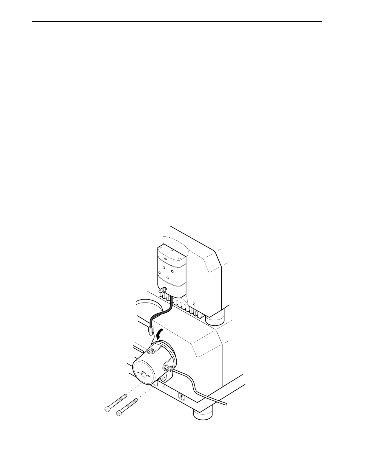
1.
a. From the Maximizer Tubing Kit, identify the following:
The red tubing labeled Inlet A1 connects the buffer container to the Maximizer valve port A1.
The blue tubing labeled Inlet A2 connects the buffer container to the Maximizer valve port A2.
The yellow tubing labeled Inlet B1 connects the buffer container to the Maximizer valve port B1.
The green tubing labeled Inlet B2 connects the buffer container to the Maximizer valve port B2.
For complete discussion of Maximizer tubing installation, refer to the Maximizer Tubing Kit
diagram.
b. Screw the tubing into the inlet connectors on the sides of the valves. Ensure a firm connection
but do not over-tighten.
Plumbing the Maximizer Valve Outlets to the Workstation Pump Inlets
c. Connect the two preformed fittings provided between the Maximizer valve ports and the
Workstation pump inlet ports. Connect to the Workstation first.
d. Because the tubing is rigid, you will need to lower the Maximizer valves in order to connect the
tubing. This requires loosening the two screws at the base of each valve so that you can tilt the
valve downward. Refer to the illustration below.
e. Insert the tubing fitting into the Maximizer outlet port and screw in the fitting.
Figure 4-4. Maximizer Plumbing
SYSTEM PLUMBING SYSTEM INSTALLATION AND SETUP
4-4
Plumbing the Maximizer.
The Maximizer Tubing Kit provides colored FEP PTFE 1/8” OD, 0.062” ID, prefitted, tubing lengths.
Plumbing the Buffer Reservoirs to the Inlets on Maximizer Valves A and B
1
0
VALVE B
B1
B2
WATER
SALT
Page 97

SYSTEM PLUMBINGSYSTEM INSTALLATION AND SETUP
4-5
2. Plumbing the Workstation pump Inlets.
a. Workstation pump inlets, attach two fittings to 1/8” (3.2 mm) OD PTFE tubing as described
earlier. (See Section 4.1, General Guidelines for Creating Your Own Tubing.)
To connect the SV5-4 buffer select valve or the SVT3-2 valve before the pump inlet, 1/8” (3.2
mm) OD PTFE tubing is used.
b. Screw the tubing into the inlet connectors on the bottom of the Workstation pump housing.
Ensure a firm connection but do not over-tighten.
c. Place opposite end of tubing in solution bottles A and B. Refer to figure 4-1. If an SV5-4 valve is
in use, attach the pump inlet tube to its common port. Refer to section 2.6.3.
TO MIXER INLET PORT
PUMPHEAD
WASHOUT PORT
INLET
PUMP A OUTLET
PUMP OUTLET
PORT
PRIMING PORT A
A
WASHOUT PORT
OUTLET
TUBING FROM BUFFERS
OR
MAXIMIZER VALVE OUTLETS
B
PUMP B OUTLET
PRESSURE
TRANSDUCER
HOUSING
PRIMING PORT B
Figure 4-5. Plumbing Connections to the Workstation Pump
3. Plumbing from the Workstation pumpheads to the Transducer (Figure 4-3).
a. Use the two pieces of tubing labeled PUMP from the tubing kit or make two fittings using 1/16”
(1.6 mm) OD orange PEEK tubing and 1/4-28 fittings, as described in section 4.1.
b. Connect the tubing to each pumphead outlet port and to each transducer inlet port. Ensure a
firm connection but do not over-tighten.
4. Plumbing from the Transducer to the Mixer (Figures 4-2 and 4-3).
a. Use the tubing labeled #1 from the tubing kit or make a fitting using 1/16” (1.6 mm) OD orange
PEEK tubing and 1/4-28 fittings.
b. Connect the tubing to the transducer outlet port and to either of the inlet ports on the mixer. Plug
the unused mixer inlet port using the plug provided for this purpose. Ensure a firm connection
but do not over-tighten.
5. Plumbing from the Mixer to the AVR7-3 Inject Valve.
a. Use the tubing labeled #2 from the tubing kit or cut a suitable length of 1/16” (1.6 mm) OD
orange PEEK tubing that will reach from the mixer outlet port to port 5 of the inject valve. Attach
1/4-28 fittings to each end.
b. Connect the tubing to the mixer outlet port and to port 5 on the inject valve. Ensure a firm
connection but do not over-tighten.
Page 98

6. Plumbing the AVR7-3 Inject Valve.
a. The inject port assembly and needle are included with each AVR7-3 inject valve. Screw this
assembly into port 2 of the valve until it is secure.
b. Connect the sample loop to ports 3 and 6.
c. Plumb the inject valve according to Figure 4-6. Use the tubes labeled "waste" or make fittings
using 1/16” (1.6 mm) OD Tefzel tubing and 1/4-28 fittings for waste lines 1 and 7.
d. Use the tube labeled #3 or make a fitting using 1/16" (1.6 mm) OD Tefzel tubing and 1/4-28
fitting to go from port 4 to the column.
Figure 4-6. Inject Valve Plumbing for an AVR7-3
7. Plumbing the UV Detector and Conductivity Monitor.
a. Connect a piece of 1/16” (1.6 mm) OD orange PEEK tubing (tube #4 in the tubing kit) between
the column outlet and the bottom inlet of the UV detector flow cell using 1/4-28 fittings. If you
are using the QuadTec detector, connect it to the flow cell which is bidirectional, using 10-32
fittings provided with the QuadTec.
b. Use the tube labeled #5 in the tubing kit or cCut approximately 8 cm of 1/16” (1.6 mm) OD
orange PEEK tubing and attach 1/4-28 fittings. Connect one end into the top of the UV detector
flow cell. Connect the other end into the Conductivity monitor flow cell which is bi-directional. If
you are using a QuadTec detector, connect tubing from its flow cell outlet using a 10-32 fitting to
either port of the Conductivity monitor using 1/4-28 fittings.
c. Place the Conductivity flow cell into the notch of the optics bench. This is a gentle push-fit.
There is a tag (with a number) attached to the conductivity cable. This number is the flow cell
constant and must be entered in the software before beginning a run. Refer to Table 5-6, page
5-10 Utilities drop-down Menu: Conductivity Flow Cell Constant Calibration.
d. For flow rates below 10 ml/min, insert the 40 psi backpressure regulator after the conductivity
monitor. Plumb the backpressure regulator following the direction of the arrow.
SYSTEM PLUMBING SYSTEM INSTALLATION AND SETUP
4-6
WASTE
WASTE
7
1
SAMPLE
INJECT
2
6
LOAD
WORKSTATION
PUMP
5
4
3
SAMPLE
LOOP
COLUMN
WASTE
WASTE
7
1
SAMPLE
INJECT
6
INJECT
2
WORKSTATION
PUMP
5
4
3
SAMPLE
LOOP
COLUMN
WASTE
WASTE
7
1
SAMPLE
INJECT
6
PURGE
2
5
4
3
SAMPLE
LOOP
WORKSTATION
PUMP
COLUMN
Page 99

Figure 4-7. Backpressure Regulator
The backpressure regulator is required to help eliminate bubbles from becoming trapped in the
detector flow cell.
When using low pressure columns such as an Econo-Pac
®
cartridge or Econo column, plumb
the 40 psi backpressure regulator at the Workstation pump outlet. This aids in seating the check
valves, preventing permanent damage to the cartridge or column.
Refer to section 2.9.5, for more information.
8. Connection to a Fraction Collector.
Connection to a BioFrac Fraction Collector
a. Use the tube labeled #6 in the fittings kit or make a fitting using 1/16” (1.6 mm) OD orange
PEEK tubing and 1/4-28 fittings.
b. Connect the fitting between the Conductivity flow cell (or the backpressure regulator or pH
monitor flow cell, if they are installed) and the BioFrac. (For complete instructions, refer to the
documentation for the BioFrac fraction collector.)
Connection to a Model 2128 Fraction Collector
a. Use the tube labeled #6 in the fittings kit or make a fitting using 1/16” (1.6 mm) OD orange
PEEK tubing and 1/4-28 fittings.
Assure that the tubing length allows unrestricted movement of the fraction collector arm.
b. Connect the fitting between the Conductivity flow cell (or the backpressure regulator or pH
monitor flow cell, if they are installed) and the drop-head of the Model 2128 or the Model 2128
diverter valve. (For complete instructions, refer to the documentation for the Model 2128 fraction
collector.)
Connection to a Model 2110 Fraction Collector and a SVT3-2 Fraction Collector Diverter
valve.
a. Connect a piece of 1/16” OD orange PEEK tubing between the Conductivity flow cell (or the
backpressure regulator, if that was installed) and the SVT3-2 valve common port (labeled
“Common”) using the 1/4-28 fittings.
b. Connect a piece of 1/16” OD Tefzel tubing from port 1 of the SVT3-2 valve (see Figure 4-3) for
use as a waste line.
c. Connect a piece of 1/16” OD Tefzel tubing from port 2 of the SVT3-2 valve (see Figure 4-3) to
the Model 2110 fraction collector drop-head. This tubing sits inside the drop-head, and no fittings
are required.
SYSTEM PLUMBINGSYSTEM INSTALLATION AND SETUP
4-7
FLOW DIRECTION
Page 100

4.3 PRIMING THE SYSTEM
Before a method can be run, the system must filled with buffer and all air bubbles purged from the system.
The following procedure should be used to prime the system for the first time and when changing buffers.
1. Priming the Workstation pump.
a. Immerse the Workstation pump A and B or Maximizer A1, A2, B1 and B2 inlet lines into a
container of HPLC grade (filtered, degassed) or other high quality water.
b. Place the 10 ml luer syringe (supplied with the fittings kit) in the priming port of pumphead A. If a
Maximizer is connected, select Inlet A1.
c. Turn the priming port counter-clockwise to open the port and gently draw water into the syringe
from the pumphead.
d. Repeat this operation until no air bubbles are visible in the inlet tubing.
e. Disconnect the pumphead outlet tube and hold a beaker up to the port. With the syringe full of
water inject water into the priming port using several short pulses to dislodge any trapped air
bubbles. Once all the bubbles have been dislodge, close priming port and reconnect the
pumphead outlet tube.
f. Repeat this priming procedure for the pump B inlet or inlets A2, B1 and B2, if a Maximizer is
connected.
2. Flush the System Through to the Fraction Collector.
a. Take the column out of line if it has been connected.
b. From the Manual screen, place the AVR7-3 injection valve into the Purge position. The AVR7-3
valve control panel is labeled with the valve type and the Workstation port where the valve is
connected. For example, if the valve is connected at Workstation port 4, the panel will be named
"AVR7-3 at port 4." The AVR7-3 valve the panel shows three valve positions Load (L), Inject (I)
and Purge (P).
c. Press the Purge buttons A and B on the front of the Workstation. The Workstation pump will run
and the indicator lights will flash green. The default purge flow rate is 10 ml/min for F10 pumps
and 40 ml/min for F40 pumps. The default purge flow rate can be changed from the
Options/Manual Setup menu option on the Manual screen.
d. Run both pumps for about 2 minutes. If a Maximizer is connected to the system, place the valve
inlets at position A2 and B2 for about a minute and then at A1 and B1 for an additional minute.
Press the Purge buttons again to stop the pump.
e. From the Manual screen place the AVR7-3 injection valve into the Inject (I) position.
f. Set the pump flow rate to 1.0 ml/min and start the pump. Water will now flow through the sample
loop, the UV Conductivity flow cells, and ultimately to the fraction collector.
g. After the system is filled, change the AVR7-3 injection valve to Load and monitor the pressure
displayed on the status bar for a few minutes. If the pressure variation exceeds ± 10 % repeat
step 1e until the pressure is stable. It is best to monitor the pressure with some backpressure on
the pumps (such as the 40 psi backpressure device). See Section 11.3 for additional
information.
SYSTEM PLUMBING SYSTEM INSTALLATION AND SETUP
4-8
 Loading...