

B&G Vulcan R Installation Manual

Vulcan R Series
In
stallation Manual
ENGLISH
www.bandg.com


Preface
Disclaimer
As Navico is continuously improving this product, we retain the
right to make changes to the product at any time which may not be
reflected in this version of the manual. Please contact your nearest
distributor if you require any further assistance.
It is the owner’s sole responsibility to install and use the equipment
in a manner that will not cause accidents, personal injury or
property damage. The user of this product is solely responsible for
observing safe boating practices.
NAVICO HOLDING AS AND ITS SUBSIDIARIES, BRANCHES AND
AFFILIATES DISCLAIM ALL LIABILITY FOR ANY USE OF THIS PRODUCT
IN A WAY THAT MAY CAUSE ACCIDENTS, DAMAGE OR THAT MAY
VIOLATE THE LAW.
Governing Language: This statement, any instruction manuals, user
guides and other information relating to the product
(Documentation) may be translated to, or has been translated from,
another language (Translation). In the event of any conflict between
any Translation of the Documentation, the English language version
of the Documentation will be the official version of the
Documentation.
This manual represents the product as at the time of printing.
Navico Holding AS and its subsidiaries, branches and affiliates
reserve the right to make changes to specifications without notice.
Copyright
Copyright © 2017 Navico Holding AS.
Warranty
The warranty card is supplied as a separate document.
In case of any queries, refer to the brand website of your unit or
system: www.bandg.com.
Compliance statements
This equipment complies with:
• CE under 2014/53/EU Directive
Preface | Vulcan R Series Installation Manual
3

• The requirements of level 2 devices of the Radio communications
(Electromagnetic Compatibility) standard 2008
• Part 15 of the FCC Rules. Operation is subject to the following
two conditions: (1) this device may not cause harmful
interference, and (2) this device must accept any interference
received, including interference that may cause undesired
operation.
The relevant Declaration of conformity is available in the product's
section at the following website: www.bandg.com.
Industry Canada
IC RSS-GEN, Sec 8.4 Warning Statement
This device complies with Industry Canada license-exempt RSS
standard(s). Operation is subject to the following two conditions: (1)
this device may not cause interference, and (2) this device must
accept any interference, including interference that may cause
undesired operation of the device.
Le présent appareil est conforme aux CNR d’Industrie
Canada applicables aux appareils radio exempts de licence.
L’exploitation est autorisée aux deux conditions suivantes: (1)
l’appareil ne doit pas produire de brouillage, et (2) l’utilisateur de
l’appareil doit accepter tout brouillage radioélectrique subi, même si
le brouillage est susceptible d’en compromettre le fonctionnement.
Warning
The user is cautioned that any changes or modifications not
expressly approved by the party responsible for compliance could
void the user’s authority to operate the equipment.
This equipment generates, uses and can radiate radio frequency
energy and, if not installed and used in accordance with the
instructions, may cause harmful interference to radio
communications. However, there is no guarantee that the
interference will not occur in a particular installation. If this
equipment does cause harmful interference to radio or television
reception, which can be determined by turning the equipment off
and on, the user is encouraged to try to correct the interference by
one or more of the following measures:
• Reorient or relocate the receiving antenna
4
Preface | Vulcan R Series Installation Manual

• Increase the separation between the equipment and receiver
• Connect the equipment into an outlet on a circuit different from
that of the receiver
• Consult the dealer or an experienced technician for help
Internet usage
Some features in this product use an internet connection to
perform data downloads and uploads. Internet usage via a
connected mobile/cell phone internet connection or a pay-per-MB
type internet connection may require large data usage. Your service
provider may charge you based on the amount of data you transfer.
If you are unsure, contact your service provider to confirm rates and
restrictions.
Countries of intended use in the EU
AT - Austria
BE - Belgium
BG - Bulgaria
CY - Cyprus
CZ - Czech Republic
DK - Denmark
EE - Estonia
FI - Finland
FR - France
DE - Germany
GR - Greece
HU - Hungary
IS - Iceland
IE - Ireland
IT - Italy
LV - Latvia
LI - Liechtenstein
LT - Lithuania
LU - Luxembourg
MT - Malta
NL - Netherlands
Preface | Vulcan R Series Installation Manual
5

NO - Norway
PL - Poland
PT - Portugal
RO - Romania
SK - Slovak Republic
SI - Slovenia
ES - Spain
SE - Sweden
CH - Switzerland
TR - Turkey
UK - United Kingdom
Trademarks
B&G® is a registered trademark of Navico Holding AS.
Navionics® is a registered trademark of Navionics, Inc.
NMEA® and NMEA 2000® are registered trademarks of the National
Marine Electronics Association.
SiriusXM® is a registered trademark of Sirius XM Radio Inc.
Fishing Hot Spots® is a registered trademark of Fishing Hot Spots Inc.
Copyright© 2012 Fishing Hot Spots.
FUSION-Link™ Marine Entertainment Standard™ is a registered
trademark of FUSION Electronics Ltd.
C-MAP® is a registered trademark of C-MAP.
SD™ and microSD™ are trademarks or registered trademarks of
SD-3C, LLC in the United States, other countries or both.
Additional mapping data: Copyright© 2012 NSI, Inc.: Copyright©
2012 by Richardson’s Maptech.
Bluetooth® is a registered trademark of Bluetooth SIG, Inc.
Navico product references
This manual refers to the following Navico products:
• Broadband Sounder™ (Broadband Sounder)
• Broadband 3G™ (Broadband 3G Radar)
• Broadband 4G™ (Broadband 4G Radar)
• DownScan Imaging™ (DownScan)
6
Preface | Vulcan R Series Installation Manual
• DownScan Overlay™ (Overlay)
• GoFree™ (GoFree)
• INSIGHT GENESIS® (Insight Genesis)
About this manual
This manual is a reference guide for installing the Vulcan Series
units.
Important text that requires special attention from the reader is
emphasized as follows:
Ú
Note: Used to draw the reader’s attention to a comment or
some important information.
Warning: Used when it is necessary to warn
personnel that they should proceed carefully to
prevent risk of injury and/or damage to equipment/
personnel.
Preface | Vulcan R Series Installation Manual
7

8
Preface | Vulcan R Series Installation Manual

Contents
11 Check the contents
11 Parts included
13 Overview
13 Front controls
14 Rear connections
15 Card reader
16 Installation
16 Mounting location
17 Bracket mounting
20 Panel mounting
20 Bezel fitment and removal
21 Transducer installation
22 Wiring
22 Guidelines
23 Power connections
24 Power Control connection
27 External alarm
27 Connecting control devices
28 NMEA 2000 backbone
30 CZone connection to NMEA 2000
31 Transducer connection
31 Radar connector
33 Software Setup
33 First time startup
33 Time and Date
33 Start line - vessel configuration
34 Rotating mast compensation
35 Data source selection
36 Device list
37 Network groups
38 Diagnostics
39 Damping
39 Calibration
39 External Alarm Setup
Contents | Vulcan R Series Installation Manual
9

39 Echosounder setup
43 StructureScan
43 Radar setup
46 Autopilot setup
46 Fuel setup
50 CZone setup
51 Wireless setup
56 NMEA 2000 setup
57 Mercury®
57 Software updates and data backup
61 Accessories
63 Supported data
63 NMEA 2000 compliant PGN List
66 Technical specifications
66 All units
68 Dimensional drawings
68 5" unit dimensional drawings
68 7" unit dimensional drawings
69 9" unit dimensional drawings
69 12" unit dimensional drawings
10
Contents | Vulcan R Series Installation Manual
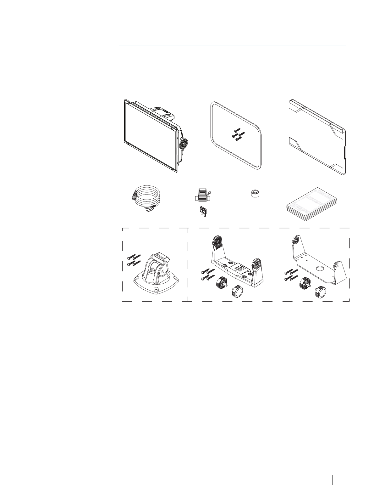
Check the contents
Check the contents of the box for your unit.
Parts included
E
N
GL
IS
H
I
nstallation M
a
nual
b
a
n
dg
.co
m
E
NGLIS
H
I
n
s
tallati
on Manual
b
a
ndg.
c
o
m
E
NGLI
S
H
I
ns
talla
tion
Manual
b
a
n
dg.co
m
E
N
GLI
S
H
I
ns
talla
tion Manual
ban
dg
.com
1
2
3
4
5
6
7
8A
8B
8C
1 Display unit
2 Panel mounting kit
• Gasket
• Mounting screws (4x #4 x 3/4" PN HD SS)
3 Sun cover
4 Cable
Combined power and NMEA 2000 cable - 5" unit
Power cable - 7", 9" and 12" units
5 Fuseholder and fuse (3 A, ATC-blade)
1
Check the contents | Vulcan R Series Installation Manual
11

6 Protective caps
2x - 5" unit
3x - 7", 9" and 12" units
7 Documentation package
• Installation manual
• Quick guide
• Mounting template
8 A: Bracket mounting kit - 5" unit
• Quick Release Bracket
• Mounting screws (4x #10 x 3/4" PN HD SS)
B: Bracket mounting kit - 7" and 9" units
• U bracket (plastic)
• Mounting screws (4x #10 x 3/4" PN HD SS)
• Bracket knobs (2x)
C: Bracket mounting kit - 12" unit
• U bracket (metal)
• Mounting screws (4x #10 x 3/4" PN HD SS)
• Bracket knobs (2x)
12
Check the contents | Vulcan R Series Installation Manual

Overview
The unit has a built-in CHIRP/Broadband, StructureScan and
ForwardScan Echosounder.
The unit can network over NMEA 2000, this allows access to sensor
data.
The unit has a built-in high speed GPS receiver (10Hz). The system
supports charts from Navionics and C-MAP as well as content
created by a variety of third party mapping providers in the AT5
format. For a full selection of available charts, visit
www.gofreemarine.com, www.c-map.com or www.navionics.com.
The unit may be mounted to the vessel with the supplied mounting
bracket, or panel mounted.
The unit is intended for 12 V DC operation and will accept the
moderate fluctuations commonly seen in DC systems.
Front controls
2
1
1 Touch screen
2 Power button
Press and hold to turn the unit ON/OFF.
Press once to display the System Controls dialog.
2
Overview | Vulcan R Series Installation Manual
13
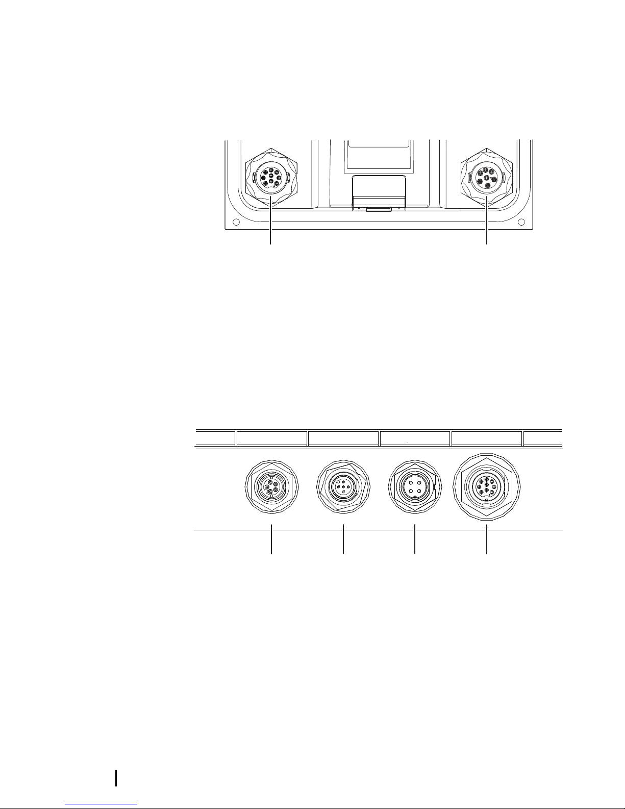
Rear connections
5" unit rear connections
1 2
1 Sonar - CHIRP, Broadband, DownScan, and SideScan
imaging (dependent on the transducer)
2 Power 12 V DC supply input and NMEA 2000
7", 9" and 12" units rear connections
1
2
3 4
RADAR NMEA2000 POWER SONAR
1 Radar - radar (Ethernet) connection
2 NMEA 2000 - data input / output
3 Power - 12 V DC supply input
4 Sonar - CHIRP, Broadband, DownScan, and SideScan
imaging (dependent on the transducer)
14
Overview | Vulcan R Series Installation Manual
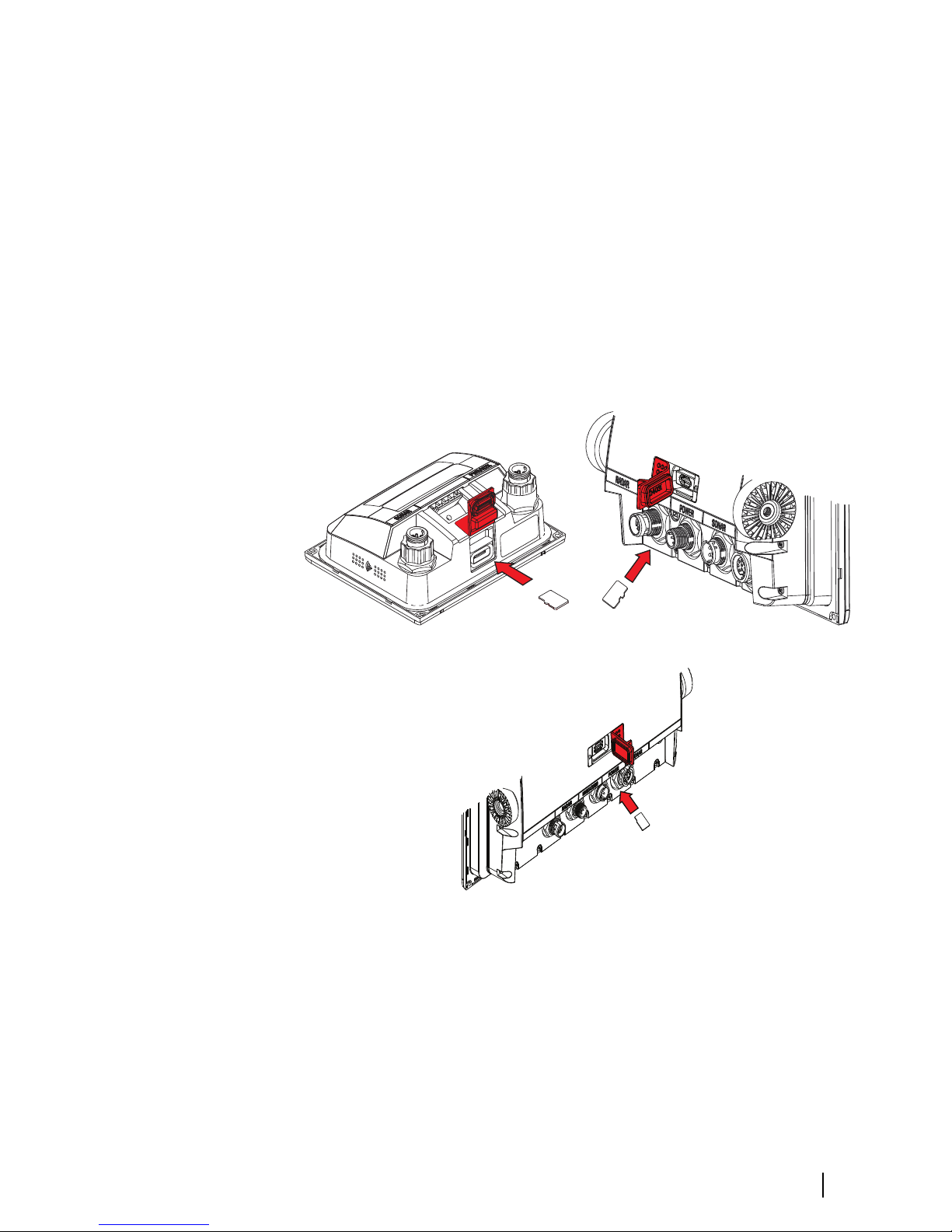
Card reader
Used for inserting a microSD memory card. The memory card can
be used for detailed chart data, software updates, transfer of user
data, and system backup.
Ú
Note: Do not download, transfer or copy files to a chart card.
Doing so can damage chart information on the chart card.
The card reader door is opened by pulling the rubber cover open.
The card reader door should always be securely shut immediately
after inserting or removing a card, in order to prevent possible water
ingress.
Card reader on the 5" unit Card reader on the 7" and 9" units
Card reader on the 12" unit
Overview | Vulcan R Series Installation Manual
15

Installation
Mounting location
Choose the mounting locations carefully before you drill or cut.
For overall width and height requirements, refer to "Dimensional
drawings" on page 68.
Do not mount any part where it can be used as a hand hold, where
it might be submerged, or where it will interfere with the operation,
launching, or retrieving of the boat.
The unit should be mounted so that the operator can easily use the
controls and clearly see the screen.
The unit has a high-contrast screen and is viewable in direct
sunlight, but for best results install the unit out of direct sunlight.
The chosen location should have minimal glare from windows or
bright objects.
The mounting location and surrounding materials may affect the
internal wireless and/or GPS performance. Metal and carbon
materials are known to impact the performance in a negative way.
Test the unit in its intended location to ensure satisfactory
reception.
An external GPS source can be added to overcome poor GPS
reception areas.
An external wireless module can be added to compatible devices to
overcome poor wireless reception areas.
Consider access to the card reader which is located in the back of
the unit.
Check that it is possible to route cables to the intended mounting
location.
Leave sufficient clearance to connect all relevant cables.
Before cutting a hole in a panel, make sure that there are no hidden
electrical wires or other parts behind the panel.
Ensure that any holes cut are in a safe position and will not weaken
the boat’s structure. If in doubt, consult a qualified boat builder, or
marine electronics installer.
Ú
Note: Where flush mounted, the enclosure should be dry and
well ventilated. In small enclosures, it may be required to fit
forced cooling.
3
16
Installation | Vulcan R Series Installation Manual
Warning: Inadequate ventilation and subsequent
overheating of the unit may cause unreliable operation
and reduced service life. Exposing the unit to
conditions that exceeds the specifications could
invalidate your warranty. – refer to "Technical specifications" on
page 66.
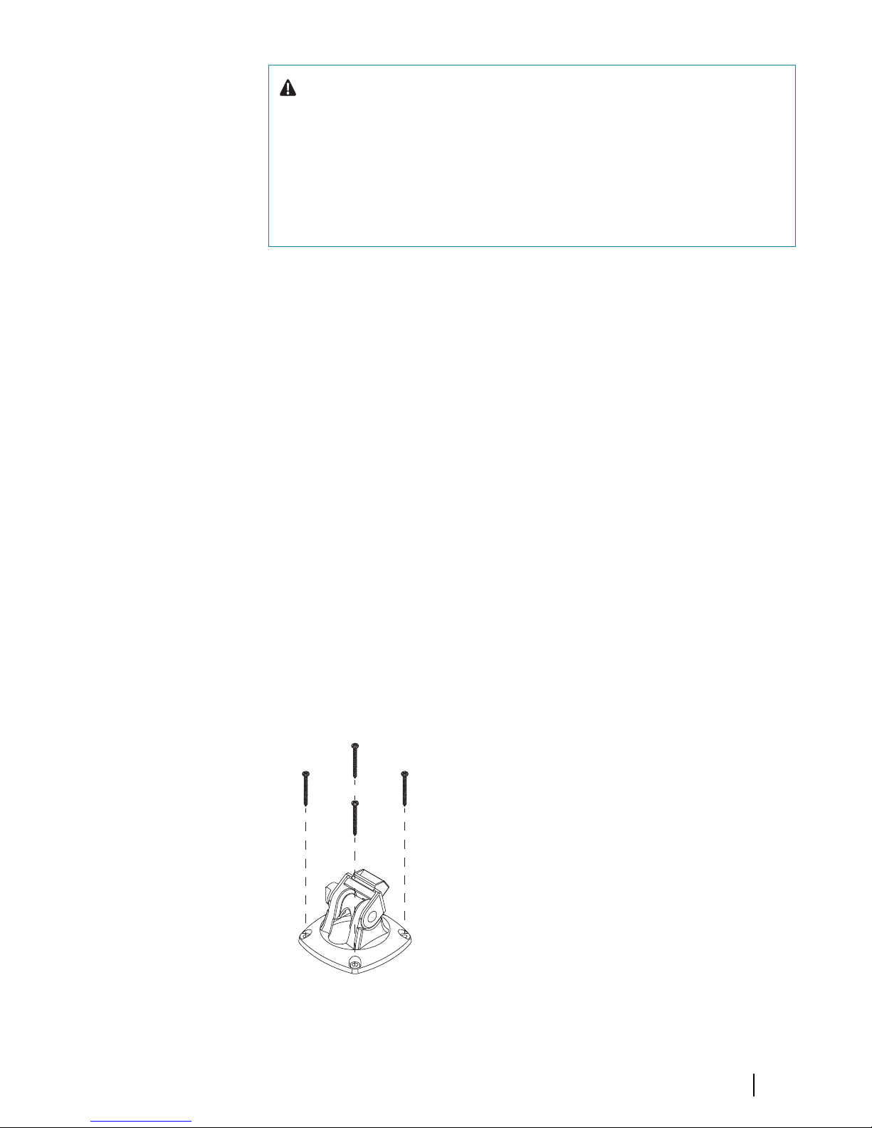
Bracket mounting
Quick release bracket mounting
The 5" unit can be mounted with the quick release bracket.
1. Place the bracket in the desired mounting location. Ensure that
the chosen location has enough height to accommodate the
unit fitted in the bracket, allows tilting of the unit and
connecting cables in the back.
Ú
Note: Ensure that the chosen location has enough height to
accommodate the unit fitted in the bracket, allows tilting of the
unit and connecting cables in the back.
2. Mark the screw locations using the bracket as a template, and
drill pilot holes.
Ú
Note: Use fasteners suited to the mounting surface material. If
the material is too thin for self-tappers, reinforce it, or mount
the bracket with machine screws and large washers. Use only
304 or 316 stainless steel fasteners.
3. Screw down the bracket.
4. Snap the unit to the bracket.
Installation | Vulcan R Series Installation Manual
17
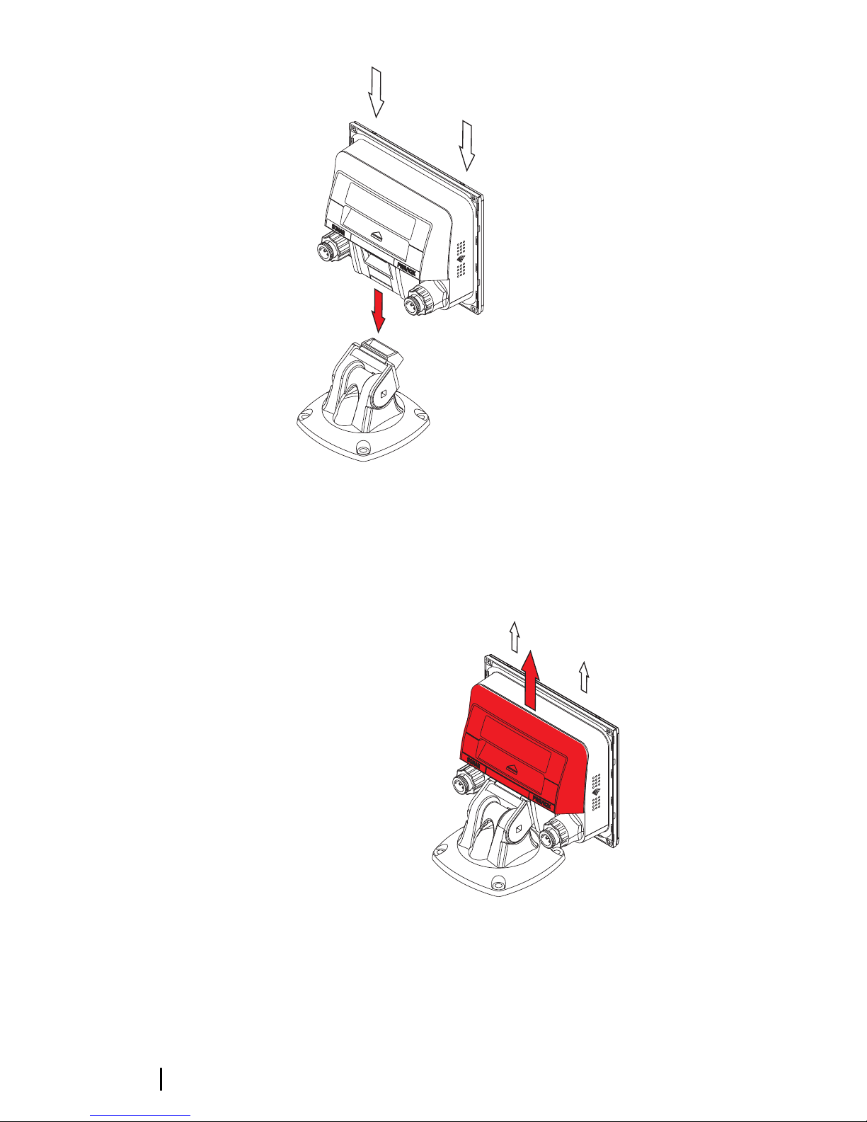
5. Tilt the unit to the desired position angle.
Removing the unit from the quick release bracket
Pull and hold the release handle and then pull the unit from the
bracket.
18
Installation | Vulcan R Series Installation Manual
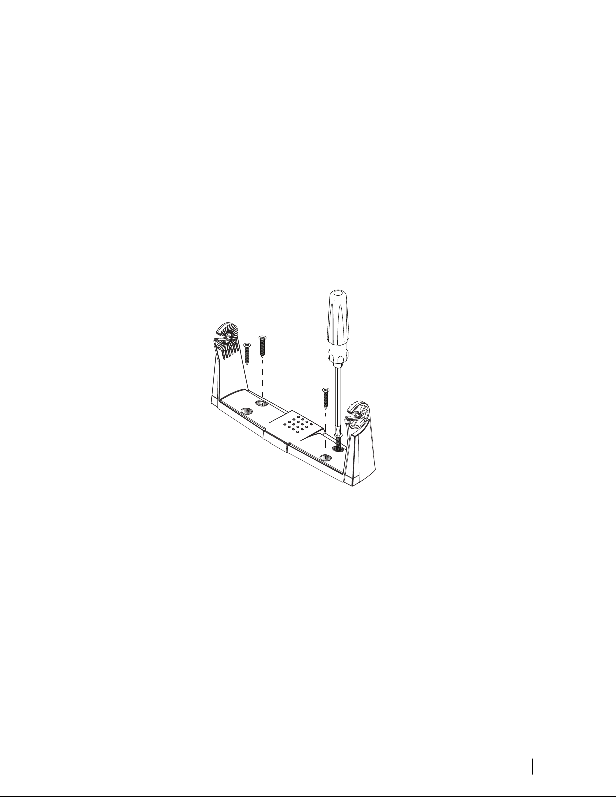
U-bracket mounting
The 7", 9" and 12" units can be mounted with the U-bracket.
1. Place the bracket in the desired mounting location. Ensure that
the chosen location has enough height to accommodate the
unit fitted in the bracket, and allows tilting of the unit. Also
adequate space is required on both sides to allow tightening
and loosening of the knobs.
2. Mark the screw locations using the bracket as a template, and
drill pilot holes. Use fasteners suited to the mounting surface
material. If the material is too thin for self-tappers, reinforce it, or
mount the bracket with machine screws and large washers. Use
only 304 or 316 stainless steel fasteners.
3. Screw down the bracket.
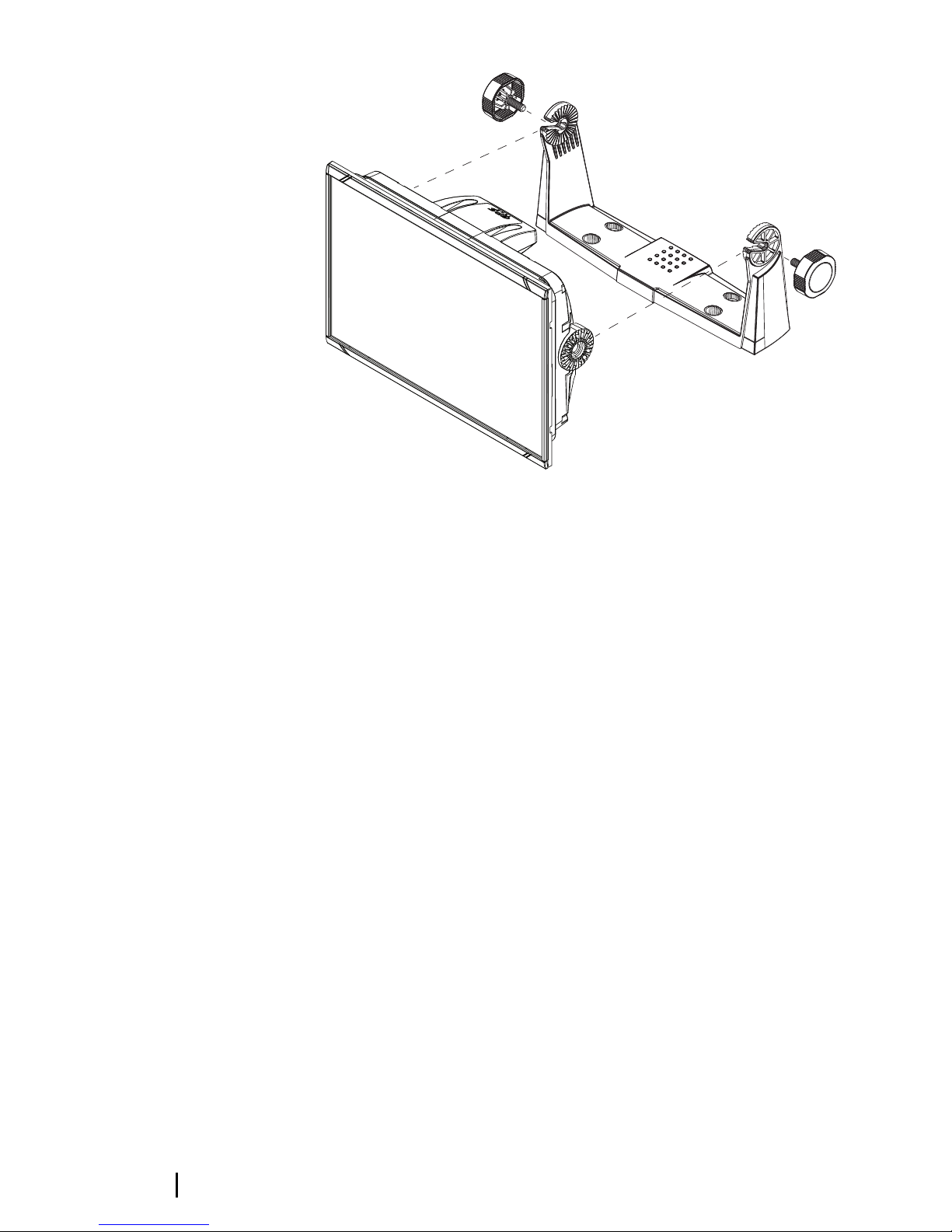
4. Mount the unit to the bracket using the knobs. Hand tighten
only. The ratchet teeth in the bracket and unit ensure a positive
grip and prevent the unit from changing from the desired angle.
Installation | Vulcan R Series Installation Manual
19
Panel mounting
The screws and gasket used for panel mounting are included in the
box.
For mounting instructions, refer to the mounting template.
Bezel fitment and removal
The bezel trim have been designed to be very low profile, and
therefore fully conceal the locking tabs that keep it from being
accidentally disengaged from the mounting flange. To release the
locking tabs, gently insert a thin object between the bezel and the
screen frame. When the first locking tab is released and an opening
is visible, carefully release the remaining locking tabs and remove
the bezel.
20
Installation | Vulcan R Series Installation Manual
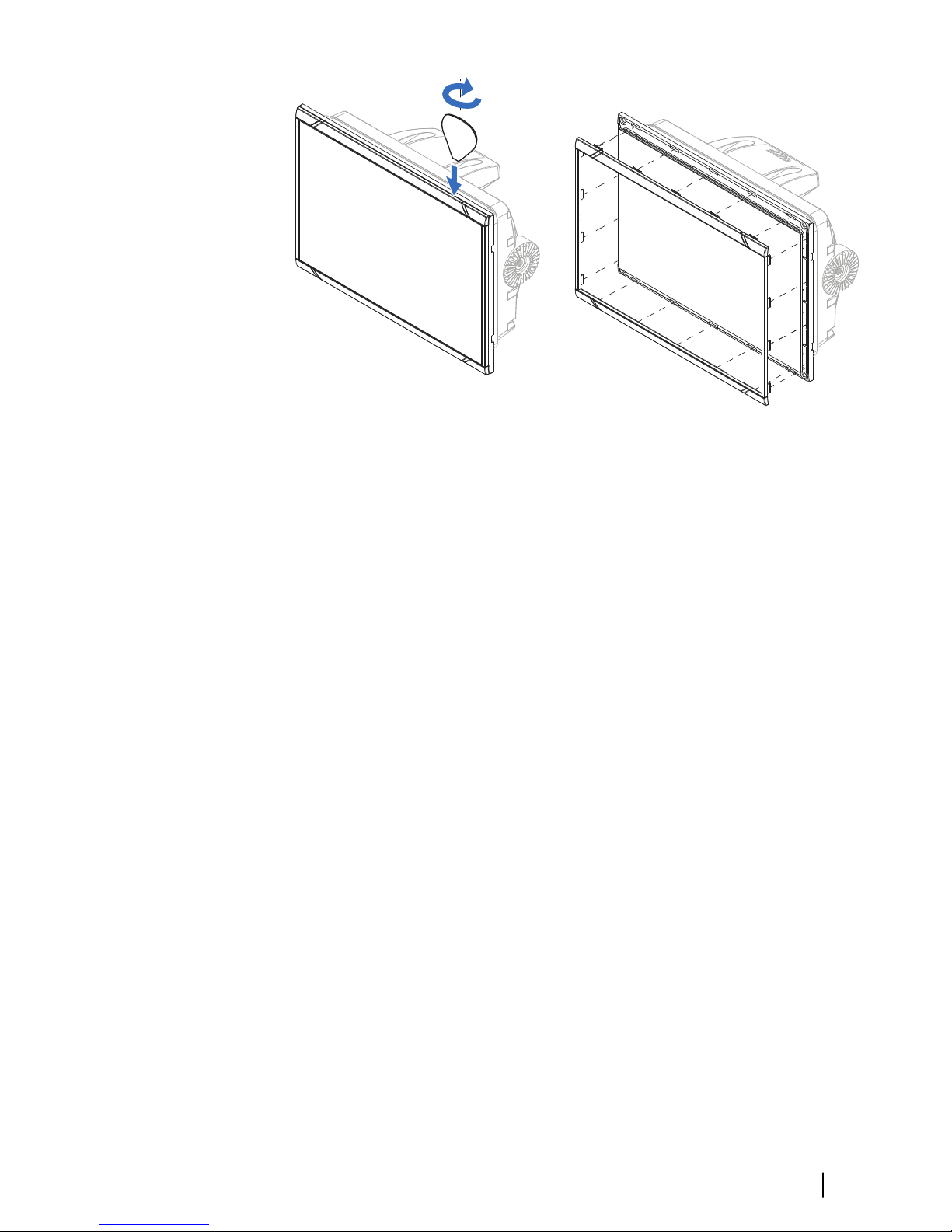
When fitting the bezel, ensure that the hook tabs on the back of the
bezel recess in to opposing slots in the screen frame. Secure the
bezel to the screen frame by gently pressing the bezel against the
screen frame.
Transducer installation
For transducer installation information, refer to separate installation
instructions included with the transducer.
Installation | Vulcan R Series Installation Manual
21
Wiring
Guidelines
Don't:
• make sharp bends in the cables
• run cables in a way that allows water to flow down into the
connectors
• run the data cables adjacent to radar, transmitter, or large/high
current carrying cables or high frequency signal cables.
• run cables so they interfere with mechanical systems
• run cables over sharp edges or burrs
Do this:
• make drip and service loops
• use cable-tie on all cables to keep them secure
• solder/crimp and insulate all wiring connections if extending or
shortening the cables. Extending cables should be done with
suitable crimp connectors or solder and heat shrink. Keep joins as
high as possible to minimize possibility of water immersion.
• leave room adjacent to connectors to ease plugging and
unplugging of cables
Warning: Before starting the installation, be sure to
turn electrical power off. If power is left on or turned on
during the installation, fire, electrical shock, or other
serious injury may occur. Be sure that the voltage of the
power supply is compatible with the unit.
Warning: The unit has a voltage rating of 12 V DC, it
is not suited for use with 24 V DC systems.
Warning: The positive supply wire (red) should
always be connected to (+) DC with the supplied fuse
or a circuit breaker (closest available to fuse rating).
4
22
Wiring | Vulcan R Series Installation Manual
 Loading...