

B&G Vulcan Installation Manual
ENGLISH
Vulcan Series
Installation Manual
bandg.com


Preface
Disclaimer
As Navico is continuously improving this product, we retain the
right to make changes to the product at any time which may not be
reflected in this version of the manual. Please contact your nearest
distributor if you require any further assistance.
It is the owner’s sole responsibility to install and use the equipment
in a manner that will not cause accidents, personal injury or
property damage. The user of this product is solely responsible for
observing safe boating practices.
NAVICO HOLDING AS AND ITS SUBSIDIARIES, BRANCHES AND
AFFILIATES DISCLAIM ALL LIABILITY FOR ANY USE OF THIS PRODUCT
IN A WAY THAT MAY CAUSE ACCIDENTS, DAMAGE OR THAT MAY
VIOLATE THE LAW.
Governing Language: This statement, any instruction manuals, user
guides and other information relating to the product
(Documentation) may be translated to, or has been translated from,
another language (Translation). In the event of any conflict between
any Translation of the Documentation, the English language version
of the Documentation will be the official version of the
Documentation.
This manual represents the product as at the time of printing.
Navico Holding AS and its subsidiaries, branches and affiliates
reserve the right to make changes to specifications without notice.
Copyright
Copyright © 2016 Navico Holding AS.
Warranty
The warranty card is supplied as a separate document.
In case of any queries, refer to the brand website of your unit or
system: bandg.com.
Regulatory statements
This equipment is intended for use in international waters as well as
coastal sea areas administered by the USA, and countries of the E.U.
and E.E.A.
Preface | Vulcan Series Installation Manual
3

This equipment complies with:
• CE under 2014/53/EU Directive
• The requirements of level 2 devices of the Radio communications
(Electromagnetic Compatibility) standard 2008
• Part 15 of the FCC Rules. Operation is subject to the following
two conditions: (1) this device may not cause harmful
interference, and (2) this device must accept any interference
received, including interference that may cause undesired
operation.
The relevant Declaration of conformity is available in the Vulcan
section on the following website: bandg.com.
Industry Canada
IC RSS-GEN, Sec 7.1.3 Warning Statement- (Required for
license exempt devices)
This device complies with Industry Canada license-exempt RSS
standard(s). Operation is subject to the following two conditions: (1)
this device may not cause interference, and (2) this device must
accept any interference, including interference that may cause
undesired operation of the device.
Le présent appareil est conforme aux CNR d’Industrie
Canada applicables aux appareils radio exempts de licence.
L’exploitation est autorisée aux deux conditions suivantes: (1)
l’appareil ne doit pas produire de brouillage, et (2) l’utilisateur de
l’appareil doit accepter tout brouillage radioélectrique subi, même si
le brouillage est susceptible d’en compromettre le fonctionnement.
Warning
The user is cautioned that any changes or modifications not
expressly approved by the party responsible for compliance could
void the user’s authority to operate the equipment.
This equipment generates, uses and can radiate radio frequency
energy and, if not installed and used in accordance with the
instructions, may cause harmful interference to radio
communications. However, there is no guarantee that the
interference will not occur in a particular installation. If this
equipment does cause harmful interference to radio or television
reception, which can be determined by turning the equipment off
4
Preface | Vulcan Series Installation Manual

and on, the user is encouraged to try to correct the interference by
one or more of the following measures:
• Reorient or relocate the receiving antenna
• Increase the separation between the equipment and receiver
• Connect the equipment into an outlet on a circuit different from
that of the receiver
• Consult the dealer or an experienced technician for help
Countries of intended use in the EU
AT - Austria
BE - Belgium
BG - Bulgaria
CY - Cyprus
CZ - Czech Republic
DK - Denmark
EE - Estonia
FI - Finland
FR - France
DE - Germany
GR - Greece
HU - Hungary
IS - Iceland
IE - Ireland
IT - Italy
LV - Latvia
LI - Liechtenstein
LT - Lithuania
LU - Luxembourg
MT - Malta
NL - Netherlands
NO - Norway
PL - Poland
PT - Portugal
RO - Romania
SK - Slovak Republic
Preface | Vulcan Series Installation Manual
5

SI - Slovenia
ES - Spain
SE - Sweden
CH - Switzerland
TR - Turkey
UK - United Kingdom
Trademarks
Lowrance® and Navico® are registered trademarks of Navico.
Simrad® is used by license from Kongsberg.
Navionics® is a registered trademark of Navionics, Inc.
NMEA® and NMEA 2000® are registered trademarks of the National
Marine Electronics Association.
SiriusXM® is a registered trademark of Sirius XM Radio Inc.
Fishing Hot Spots® is a registered trademark of Fishing Hot Spots Inc.
Copyright© 2012 Fishing Hot Spots.
FUSION-Link™ Marine Entertainment Standard™ is a registered
trademark of FUSION Electronics Ltd.
C-MAP is a trademark of Jeppesen.
The terms HDMI and HDMI High-Definition Multimedia Interface,
and the HDMI Logo are trademarks or registered trademarks of
HDMI Licensing LLC in the United States and other countries.
SD™ and microSD™ are trademarks or registered trademarks of
SD-3C, LLC in the United States, other countries or both.
Wi-Fi® is a registered trademark of the Wi-Fi Alliance®.
Additional mapping data: Copyright© 2012 NSI, Inc.: Copyright©
2012 by Richardson’s Maptech.
Bluetooth® is a registered trademark of Bluetooth SIG, Inc.
Navico product references
This manual refers to the following Navico products:
• Broadband Sounder™ (Broadband Sounder)
• DownScan Imaging™ (DownScan)
• DownScan Overlay™ (Overlay)
• GoFree™ (GoFree)
6
Preface | Vulcan Series Installation Manual
• INSIGHT GENESIS® (Insight Genesis)
• SonicHub® (SonicHub)
About this manual
This manual is a reference guide for installing the Vulcan Series
units.
Important text that requires special attention from the reader is
emphasized as follows:
Ú
Note: Used to draw the reader’s attention to a comment or
some important information.
Warning: Used when it is necessary to warn
personnel that they should proceed carefully to
prevent risk of injury and/or damage to equipment/
personnel.
Preface | Vulcan Series Installation Manual
7

8
Preface | Vulcan Series Installation Manual

Contents
11 Check the contents
11 Vulcan 5 box contents
12 Vulcan 7 FS box contents
13 Overview
13 Front controls
14 Rear connections
16 Card reader
17 Installation
17 Mounting location
18 Bracket mounting
20 Panel mounting
20 Transducer installation
21 Wiring
21 Guidelines
22 Power Connections
23 Power Control connection
24 External alarm
25 Connecting control devices
25 NMEA 2000 backbone
27 CZone connection to NMEA 2000
28 Transducer connection
29 Software Setup
29 First time startup
29 Time and Date
29 Data source selection
31 Sonar setup
32 StructureScan
33 Autopilot setup
44 Fuel setup
47 CZone setup
48 Wireless setup
51 NMEA 2000 setup
52 Software updates and data backup
Contents | Vulcan Series Installation Manual
9

55 Accessories
56 Supported data
56 NMEA 2000 compliant PGN List
61 Specifications
61 Mechanical/Environmental
61 Electrical
62 Interfaces
63 Dimensional drawings
63 Vulcan 5 Dimensional drawings
63 Vulcan 7 FS Dimensional drawings
10
Contents | Vulcan Series Installation Manual
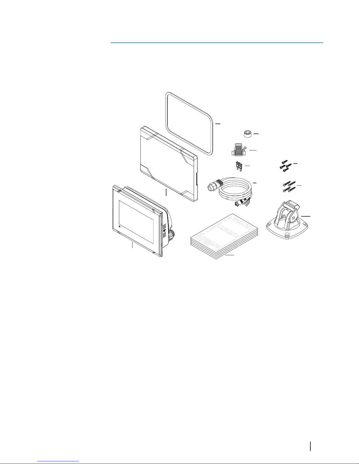
Check the contents
Check the contents of the box for your unit.
Vulcan 5 box contents
E
NGLIS
H
Installation
M
anual
bandg.
com
E
NGLISH
In
stallation M
anua
l
band
g
.com
E
NGLISH
In
stalla
t
ion Manual
bandg.
c
om
E
NGLI
SH
In
stall
at
ion Manual
bandg
.
com
1
2
4
5
6
7
10
9
11
8
3
1 Vulcan 5
2 Sun cover
3 Panel mount gasket
4 Cap (2x on NMEA 2000 and Sonar connectors)
5 Fuse holder (ATC blade)
6 Fuse (3 amp)
7 Power/NMEA 2000 cable
8 Panel mount screws (4x #10 x 1/2" PN HD SS)
9 Quick Release Bracket screws (4x #10 x 3/4" PN HD SS)
10 Quick Release Bracket
11 Documentation pack
1
Check the contents | Vulcan Series Installation Manual
11
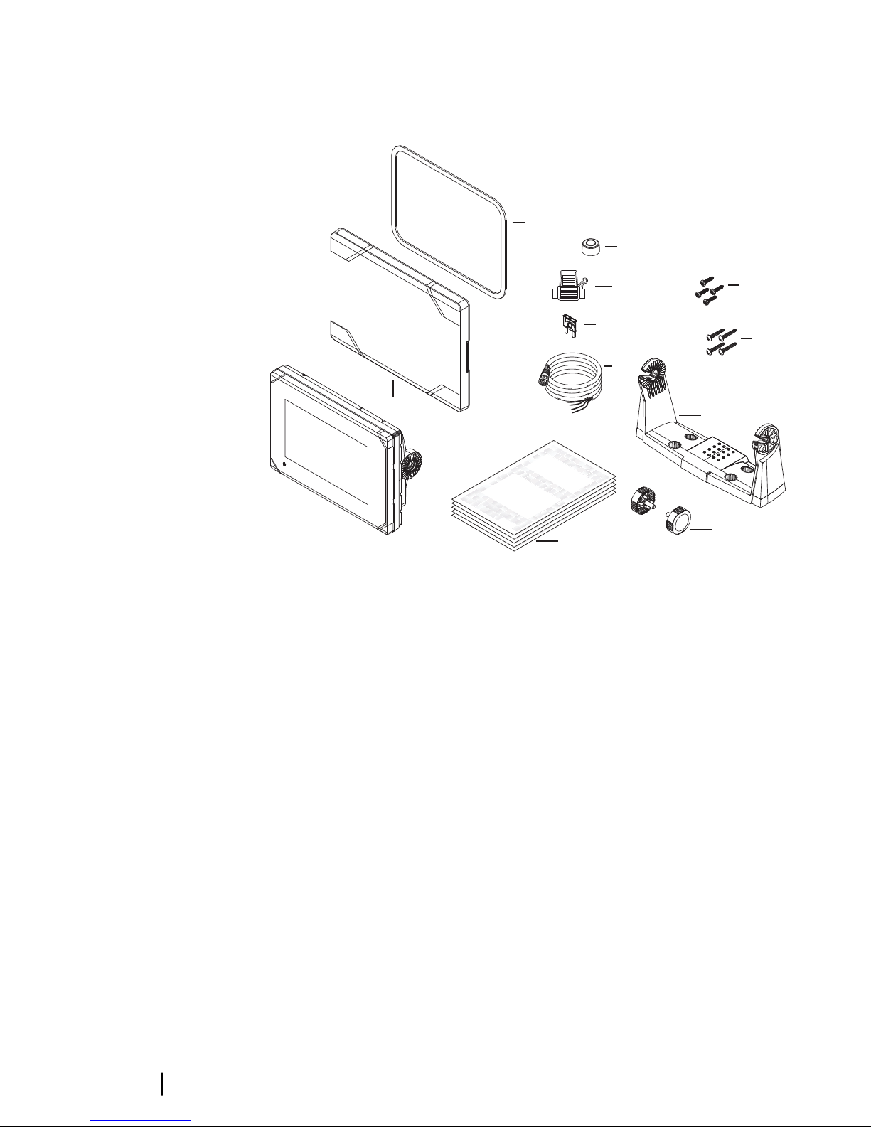
Vulcan 7 FS box contents
E
NGLISH
I
nstallati
on Manua
l
band
g.com
E
NGLIS
H
Install
a
tion Manual
band
g
.com
E
NGLIS
H
Installa
tion
M
anua
l
bandg.
c
o
m
ENGLISH
I
nstalla
tion Manual
band
g
.
com
1
2
4
5
6
7
10
9
12
11
8
3
1 Vulcan 7 FS
2 Sun cover
3 Panel mount gasket
4 Caps (2x, on NMEA 2000 and Sonar connectors)
5 Fuse holder (ATC blade)
6 Fuse (3 amp)
7 Power cable
8 Panel mount screws (4x #10 x 1/2" PN HD SS)
9 U Bracket mount screws (4x #10 x 3/4" PN HD SS)
10 U Bracket
11 Bracket knobs (2x)
12 Documentation pack
12
Check the contents | Vulcan Series Installation Manual
Overview
The unit has a built-in CHIRP/Broadband and StructureScan sonar.
The Vulcan units can network over NMEA 2000, this allows access to
sensor data.
The unit has built-in high speed GPS receiver (10Hz) and supports
Insight charts from Navico including Insight Genesis. The system
also supports charts from Navionics and Jeppesen as well as
content created by a variety of third party mapping providers in the
AT5 format. For a full selection of available charts, visit
gofreeshop.com, c-map.jeppesen.com, or navionics.com.
The unit may be mounted to the vessel with the supplied mounting
bracket, or panel mounted on the dash.
The unit is intended for 12 V DC operation and will accept the
moderate fluctuations commonly seen in DC systems.
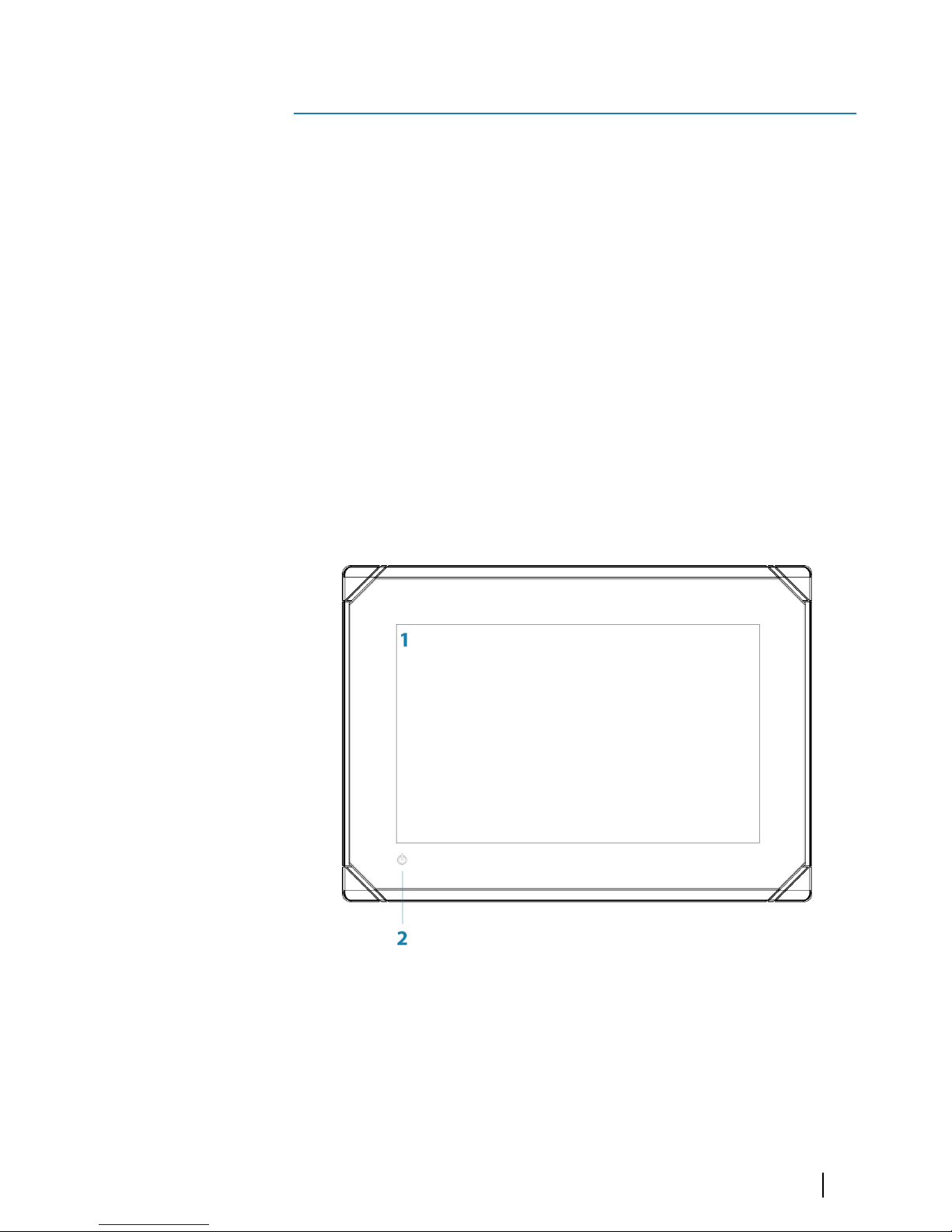
Front controls
1 Touch screen
2 Power button
Press and hold to turn the unit ON/OFF.
Press once to display the System Controls dialog.
2
Overview | Vulcan Series Installation Manual
13
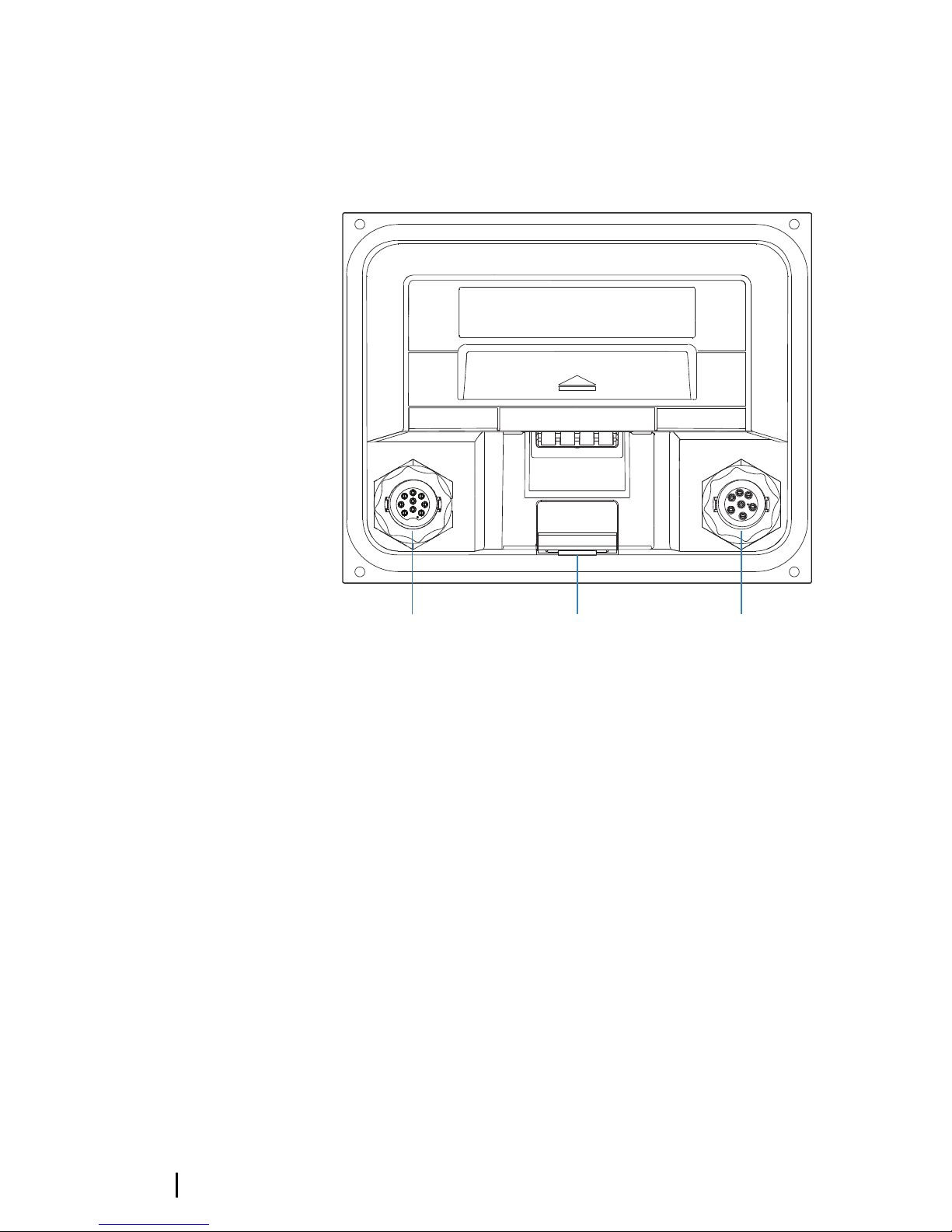
Rear connections
Vulcan 5 rear connections
SONAR
PWR/N2K
1 2 3
1 Sonar - CHIRP, Broadband, DownScan, and SideScan
imaging (dependent on the transducer)
2 Card reader
3 Power 12 V DC supply input and NMEA 2000
14
Overview | Vulcan Series Installation Manual
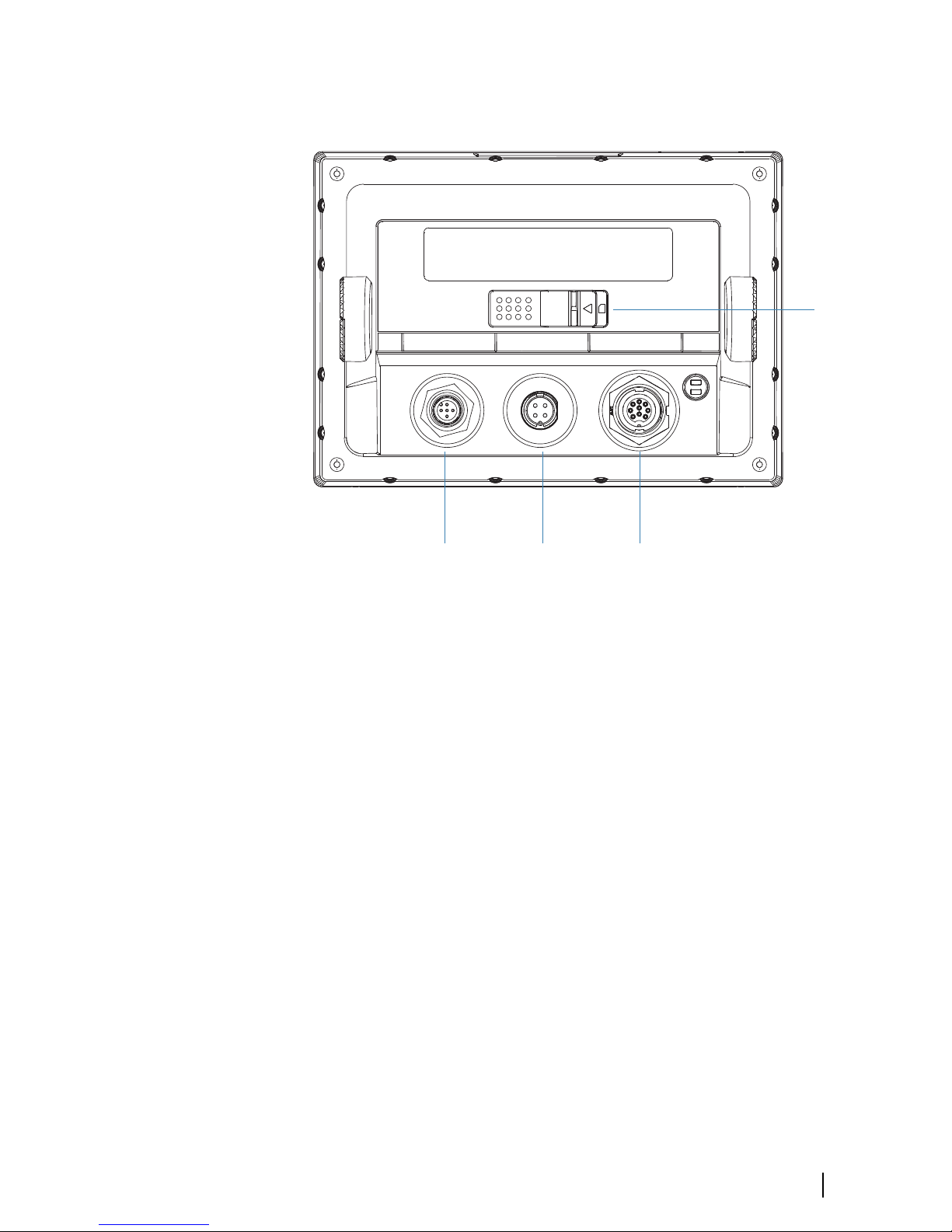
Vulcan 7 FS rear connections
NMEA2000 POWER SONAR
1
2
3
4
1 NMEA 2000 - data input / output
2 Power - 12 V DC supply input
3 Sonar - CHIRP, Broadband, DownScan, and SideScan
imaging (dependent on the transducer)
4 Card reader
Overview | Vulcan Series Installation Manual
15
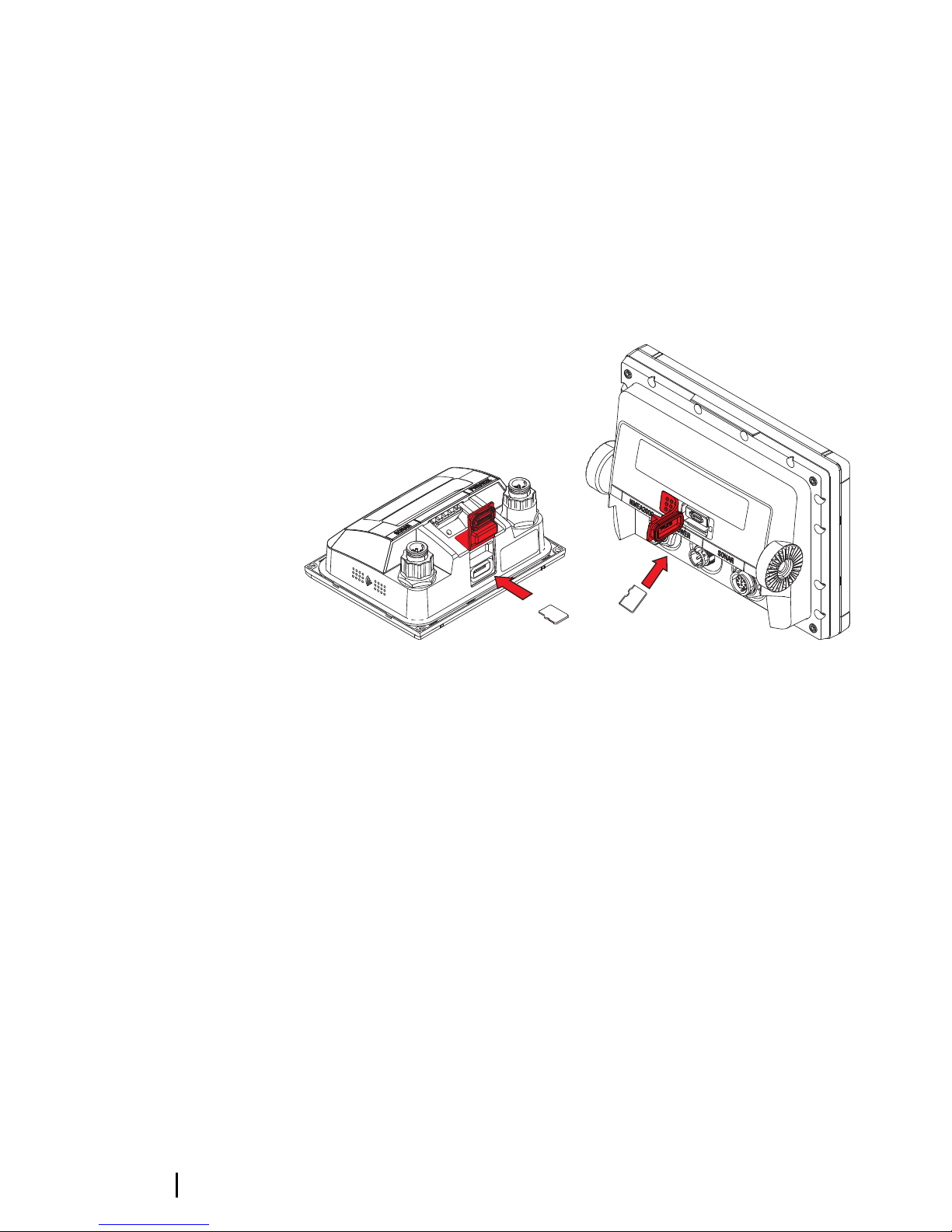
Card reader
Used for attaching a microSD memory card. The memory card can
be used for detailed chart data, software updates, transfer of user
data, and system backup.
The card reader door is opened by pulling the rubber cover open.
The card reader door should always be securely shut immediately
after inserting or removing a card, in order to prevent possible water
ingress.
Card reader on the Vulcan 5 Card reader on the Vulcan 7 FS
16
Overview | Vulcan Series Installation Manual
Installation
Mounting location
Choose the mounting locations carefully before you drill or cut. The
unit should be mounted so that the operator can easily use the
controls and clearly see the screen. Be sure to leave a direct path for
all of the cables. The unit has a high-contrast screen, and is viewable
in direct sunlight, but for best results install the unit out of direct
sunlight. The chosen location should have minimal glare from
windows or bright objects.
Ensure that any holes cut are in a safe position and will not weaken
the boat’s structure. If in doubt, consult a qualified boat builder, or
marine electronics installer.
Before cutting a hole in a panel, make sure that there are no hidden
electrical wires or other parts behind the panel.
Check that it is possible to route cables to the intended mounting
location.
Leave sufficient clearance to connect all relevant cables.
Do not mount any part where it can be used as a hand hold, where
it might be submerged, or where it will interfere with the operation,
launching, or retrieving of the boat.
The mounting location may affect the internal GPS receiver. Test the
unit in its intended location to ensure satisfactory reception. An
external GPS source can be added to overcome poor reception
areas.
Choose an area where the unit will not be subjected to excessive
vibration, or heat.
Good ventilation is required.
Warning: Inadequate ventilation may cause the unit
to overheat. The unit is designed to operate in
temperatures from -15° C to +55° C (+5° F to +131° F).
For overall width and height requirements, refer to "Dimensional
drawings" on page 63.
Choose a location that will not expose the unit to conditions that
exceed the IP rating - refer to "Specifications" on page 61.
3
Installation | Vulcan Series Installation Manual
17
Warning: When installing, ensure appropriate safety
equipment is used. For example, ear muffs, protective
glasses, gloves and a dust mask. Power tools may
exceed safe noise levels, and can cast off dangerous
projectiles. The dust from many materials commonly
used in boat construction may cause irritation or
damage to eyes, skin, and lungs.
Bracket mounting
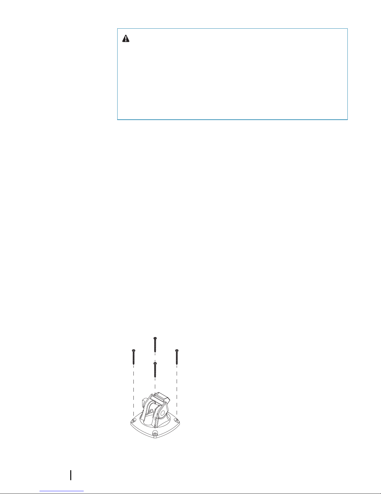
Quick release bracket mounting
The Vulcan 5 can be mounted with the quick release bracket.
1. Place the bracket in the desired mounting location. Ensure that
the chosen location has enough height to accommodate the
unit fitted in the bracket, allows tilting of the unit and
connecting cables in the back.
Ú
Note: Ensure that the chosen location has enough height
to accommodate the unit fitted in the bracket, allows tilting
of the unit and connecting cables in the back.
2. Mark the screw locations using the bracket as a template, and
drill pilot holes.
Ú
Note: Use fasteners suited to the mounting surface
material. If the material is too thin for self-tappers, reinforce
it, or mount the bracket with machine screws and large
washers. Use only 304 or 316 stainless steel fasteners.
3. Screw down the bracket.
4. Snap the unit to the bracket.
18
Installation | Vulcan Series Installation Manual
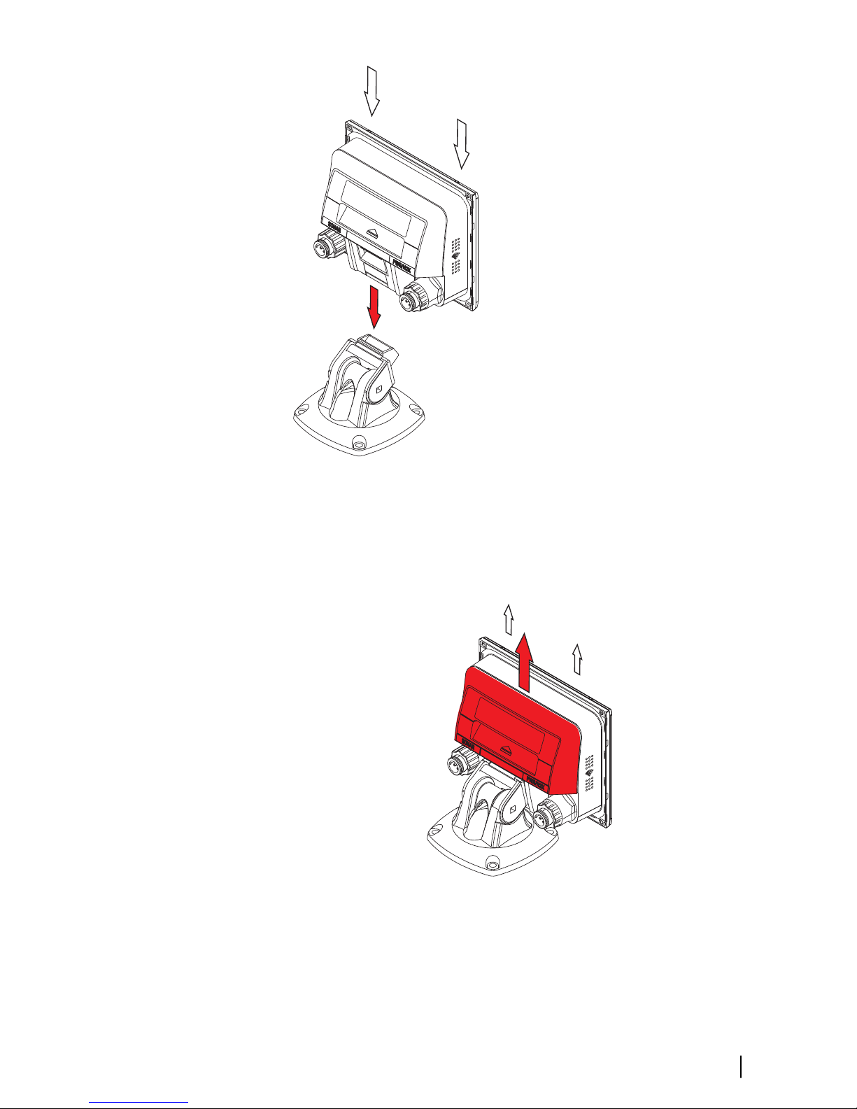
5. Tilt the unit to the desired position angle.
Removing the unit from the quick release bracket
Pull and hold the release handle and then pull the unit from the
bracket.
U Bracket mounting
The Vulcan 7 FS can be mounted with the U bracket.
Installation | Vulcan Series Installation Manual
19
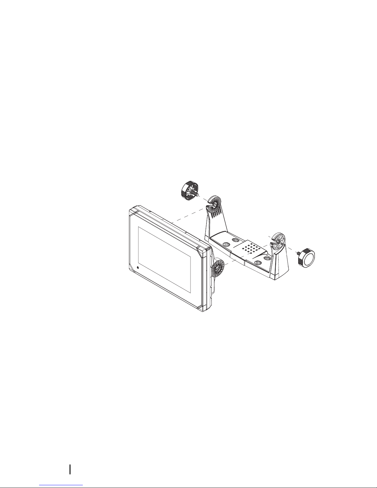
1. Place the bracket in the desired mounting location. Ensure that
the chosen location has enough height to accommodate the
unit fitted in the bracket, and allows tilting of the unit. Also
adequate space is required on both sides to allow tightening
and loosening of the knobs.
2. Mark the screw locations using the bracket as a template, and
drill pilot holes. Use fasteners suited to the mounting surface
material. If the material is too thin for self-tappers, reinforce it, or
mount the bracket with machine screws and large washers. Use
only 304 or 316 stainless steel fasteners.
3. Screw down the bracket.
4. Mount the unit to the bracket using the knobs. Hand tighten
only. The ratchet teeth in the bracket and unit case ensure a
positive grip and prevent the unit from changing from the
desired angle.
Panel mounting
The screws and gasket used for panel mounting are included in the
box. For mounting instructions, refer to the Panel mounting
template.
Transducer installation
For transducer installation information, refer to separate installation
instructions included with the transducer.
20
Installation | Vulcan Series Installation Manual
 Loading...