

B & G H3000 Pilot Owner's Manual

Pilot Handbook
www.bandg.com

H3000 Pilot Handbook___________________________________________________
NOTIFICATION
The information contained in this document is subject to change without
prior notice.
Navico UK Ltd. shall not be liable for errors contained herein or for
incidental or consequential damages in connection with the furnishing,
performance, or use of this document.
No part of this work covered by the copyright hereon may be reproduced
or otherwise copied without prior permission from Navico UK Ltd.
© 2008 Navico UK Ltd. All rights reserved.
Tel: +44 1794 518448
Fax: +44 1794 518077
www.bandg.com
Email: sales@bandg.com
Navico UK Ltd.
Premier Way, Abbey Park
Romsey, SO51 9DH
United Kingdom
Email: support@bandg.com
HB-3001-02
2

___________________________________________________H3000 Pilot Handbook
LIABILITY AND SAFETY WARNINGS
Navico Limited accept no responsibility for the use and/or operation of this equipment. It is
the user’s responsibility to ensure that under all circumstances the equipment is used for the
purposes for which it has been designed.
Warning: Electrical Hazard
This equipment uses high voltage electr ical power. Contact with high voltages may result in
injury and/or loss of life.
Warning: Calibration
The safe operation of this equipment is dependent on accurate and correct calibration.
Incorrect calibration of this equipment may lead to false and inaccurate navigational readings
placing the yacht into danger.
Warning: Operational Hazard
The H3000 system is an Electronic Navigation aid and is designed to assist in the navigation
of your yacht. It is not designed to totally replace conventional navigation procedures and
precautions and all necessary precauti ons sho uld be t ake n to ensure that the yacht is not placed
into danger.
The Pilot is an aid to steering the vessel. It is the users responsibility to ensure the safe control
and movement of the vessel at all times.
Warning: Navigation Hazard
The Pilot must be fully commissioned and a satisfactory sea-trial completed before the Pilot is
used to steer the vessel. Failure to do so could endanger life and/or other vessels.
Caution: Electrical Supply
This equipment is designed for use with a power su pply source of 12V dc. The application of
any other power supply may result in permanent damage to the equipment.
Caution: Cleaning
The use of alcohol or solvent-based cleaners will damage this equipment and any warranty in
force will be invalidated.
Caution: Display Installation
Displays installed into locations manufactured from conductive materials ( e.g. Steel, Carbon
Fibre etc.) should be insulated from the structure to prevent damage to the casings as a result
of the effects of electrolysis.
Caution: Processor Installation
All B&G Processors should be installed below decks in a dry location protected from wat er
and moisture.
Power Off Disclaimer
When in standby mode the H3000 system continues to consume power. To conserve the
vessel’s battery life switch off power at the main breaker.
HB-3001-02
3

H3000 Pilot Handbook___________________________________________________
CONTENTS
NOTIFICATION .......................................................................................................... 2
LIABILITY AND SAFETY WARNINGS ................................................................. 3
ABOUT B&G ................................................................................................................ 6
ABOUT THIS MANUAL .......................................................................................... 6
INTRODUCTION ........................................................................................................ 7
SYSTEM OVERVIEW .............................................................................................. 7
H3000 SYSTEM EXAMPLE ...................................................................................... 8
OPERATING INFORMATION ............................................................................... 15
GETTING STARTED .............................................................................................. 16
GPD KEYS EXPLAINED ....................................................................................... 16
GPD MAIN MENU .................................................................................................. 21
TIMER .................................................................................................................. 21
PILOT ................................................................................................................... 21
INSTRUMENTS .................................................................................................. 24
GPS ....................................................................................................................... 26
TRIP CONTROL ................................................................................................. 27
REMOTE UNITS ................................................................................................. 28
SETUP ...................................................................................................................... 29
ALARMS ............................................................................................................. 29
CALIBRATION ................................................................................................... 31
COMPASS CALIBRATION ............................................................................... 31
HALCYON 2000 COMPASS CALIBRATION PROCEDURE(Auto Swing) ... 32
HALCYON GYRO COMPASS CALIBRATION and SETUP .......................... 34
HEADING SOURCE SELECTION .................................................................... 35
DAMPING ........................................................................................................... 35
DYNAMIC DAMPING ....................................................................................... 35
THIS DISPLAY ....................................................................................................... 36
PAGE SETUP ...................................................................................................... 37
SCREEN ............................................................................................................... 38
SHOW ALARMS ON THIS DISPLAY .............................................................. 38
FAVOURITES ..................................................................................................... 38
UNITS .................................................................................................................. 39
UNIT INFORMATION ....................................................................................... 40
KEY LOCK .......................................................................................................... 40
COMMISSION ........................................................................................................ 40
USE SOG AS SPEED INPUT ............................................................................. 41
HEADING ............................................................................................................ 41
PILOT ................................................................................................................... 42
START COMPASS SWING ................................................................................ 42
SYSTEM .............................................................................................................. 42
PILOT OPERATION ................................................................................................ 43
ENGAGING THE PILOT ........................................................................................ 43
DIS-ENGAGING THE PILOT ................................................................................ 43
CHANGING THE PILOT COURSE ....................................................................... 43
PILOT MODE SELECTION ................................................................................... 44
HB-3001-02
4

___________________________________________________H3000 Pilot Handbook
STEER TO COMPASS (COMP) ...................................................................... 44
STEER TO APPARENT WIND ANGLE (WIND A) ...................................... 45
STEER TO TRUE WIND ANGLE (WIND T) ................................................. 45
STEER TO WAYPOINT (NAV) ......................................................................... 45
STEER TO TARGET TWA (POLAR) ................................................................ 47
POWER (MANUAL STEER) ......................................................................... 47
RESPONSE MODE ................................................................................................. 48
Response Settings with Halcyon Gyro-Stabilised Compass ................................ 48
Response Settings with Halcyon 2000 compass or other sources ........................ 48
ACTION ................................................................................................................... 49
SETUP ...................................................................................................................... 51
COMMISSIONING ................................................................................................. 52
PILOT COMMISSION ............................................................................................. 56
DOCKSIDE SETUP ................................................................................................. 56
SEA TRIAL .............................................................................................................. 60
ADVANCED SETTINGS ........................................................................................ 64
SPEED SOURCE ................................................................................................. 65
AUTOMATIC RESPONSE ................................................................................. 65
RECOVERY MODE ............................................................................................ 66
NAV SOURCE ..................................................................................................... 67
MAGNETIC DIP ZONE ...................................................................................... 68
PILOT SPEED CAL ............................................................................................ 69
INSTALLATION INFORMATION ......................................................................... 72
CABLE AND CONNECTION INFORMATION ................................................... 72
EMC Compliance ................................................................................................. 72
General Wiring Notes ........................................................................................... 72
Pilot Drive Unit Cables ........................................................................................ 73
ACP Unit Terminal Details .................................................................................. 74
Clutch Voltage Selection ...................................................................................... 75
Dip Switch Location ............................................................................................. 76
ACP WIRING CONNECTIONS ............................................................................. 77
Network and Alarm Connections ......................................................................... 77
Pilot Display Connections .................................................................................... 78
Network Installation ................................................................................................. 79
MOB, Joystick, Hand-held Controller Connections ............................................ 80
Hydraulic Ram Drive Connections ...................................................................... 81
Rotary Drive Connections .................................................................................... 82
Sterndrive Unit Connections ................................................................................ 83
Proportional Solenoid Connections ...................................................................... 84
Continuous Drive Connections ............................................................................ 85
Linear Feedback Connections .............................................................................. 86
Halcyon 2000 Compass ........................................................................................ 87
Halcyon Gyro Stabilised Compass Connections .................................................. 88
Direct Speed Input Connections ........................................................................... 89
Using a non B&G speed sensor ............................................................................ 90
ROTARY RUDDER REFERENCE SENSOR ........................................................ 91
LINEAR FEED BACK UNIT .............................................................................. 94
DIAGNOSTIC DATA ................................................................................................ 95
FAULT DIAGNOSIS ................................................................................................. 96
HB-3001-02
5

H3000 Pilot Handbook___________________________________________________
ABOUT B&G
B&G has welcomed the constant challenge to develop new electronic
solutions for every sailor’s need. Harnessing technical developments and
providing proven solutions has continued to be the focus that keeps B&G
on the leading edge of advanced marine electronics.
Proven in the worlds most testing environments, B&G offers the most
accurate and reliable systems used by blue water cruisers, single-handed
racers and record breakers alike firmly establishing ourselves as one of t he
leading innovators of the most highly advanced marine electronics.
B&G is renowned for tried and trusted solutions and is ever evolving to
offer the best technology to the customer.
B&G’s Promise.
“Uncompromising performance, precision and reliability from both our
products and our people”.
ABOUT THIS MANUAL
Instructions in this manual describe the controls and calibration of your
H3000 Pilot system. You can also use the controls on the B&G
RemoteVision details of which can be found in the RemoteVision
handbook.
The icons shown below are used in this manual
Icon Meaning
Indicates that the function is
available on H3000 Performance
systems only
HB-3001-02
6

___________________________________________________H3000 Pilot Handbook
INTRODUCTION
SYSTEM OVERVIEW
The H3000 Pilot fully integrates with the H3000 instrument system, both
in terms of style and performance. The instrument system transmits sensor
information via the B&G Fastnet network to the ACP Pilot computer unit.
The Pilot computer processes the sensor data and then sends signals to the
rudder drive system (linear ram, rotary drive or hydraulic pump) to steer
the vessel on the desired course. The complex learning algorithms used in
the Pilot computer ensure that the steering performance is optimised for
the sea and weather conditions, and quickly responds to any changes that
may occur.
Control of the Pilot is via the keys on any one of the dedicated Graphical
Pilot Displays (GPD). Each display acts as a master allowing control of
the Pilot from any station.
H3000 Pilots are available with a wide range of powerful and reliable 12V
or 24V dc rudder drive units suitable for boats of over 7m (23ft). The ACP
(Advanced Control Program) Pilot computers are supplied in two
specifications ACP1 or ACP2 (Advanced Control Programming)
depending on the size of vessel, power requirements and options in use.
The H3000 Pilot can be used for both sailing and power boats that have a
H3000 System installed.
HB-3001-02
7
H3000 Pilot Handbook___________________________________________________
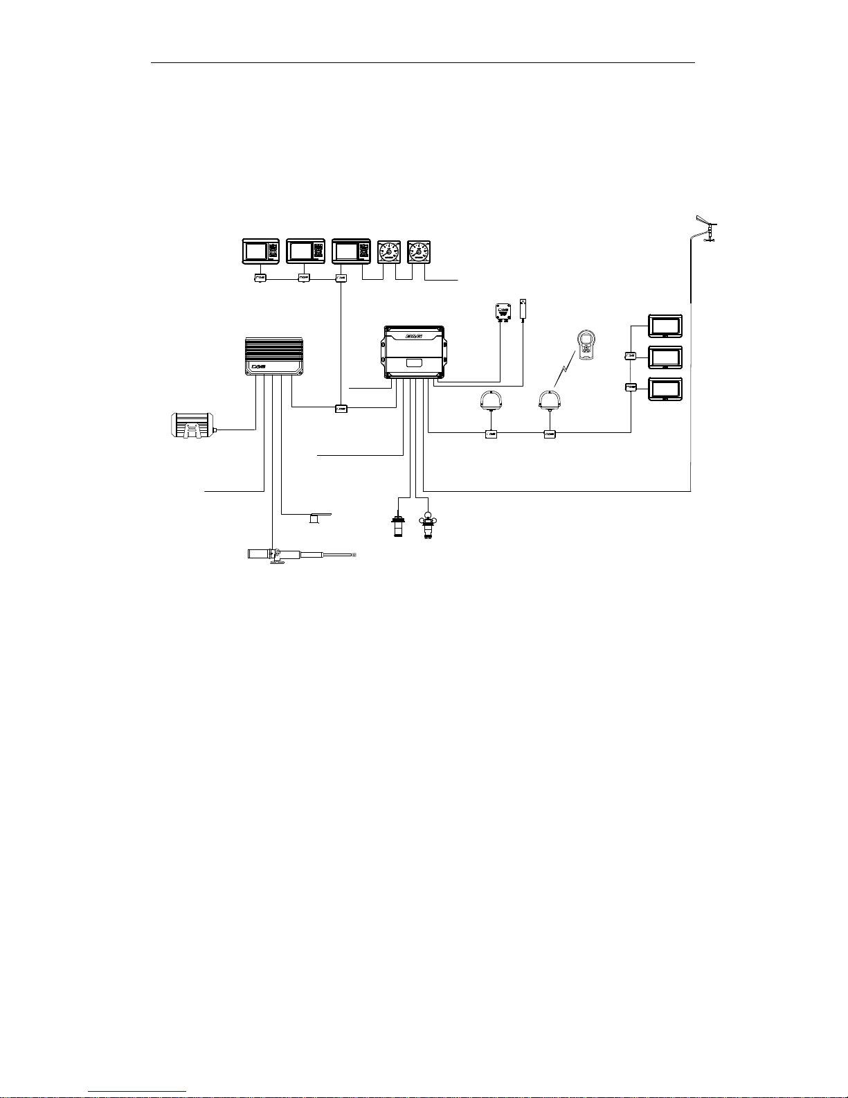
H3000 System Example
FFD
ACP 2 Pilot
Processor
GFDGPD
Analogue
Displays
H3000 CPU
Hercules
Performance
12V
Barometric
Pressure & Air
Temperature
Sensor
RemoteVision
Vertical Masthead
Unit
20/20
Displays
3-Axis Gyro -
Stabilised
Compass
12 / 24 V
Pilot Drive Unit
12 V
NMEA IN / OUT
Rudder
Reference
Unit
Speed &
Depth
Sensors
Halcyon
2000
Compass
RemoteVision
Wireless Port
H3000 System example with Pilot
Above is an example of a typical H3000 system. At the centre of the
system is the Central Processor Unit (CPU).
All sensor information is fed back to the CPU and can be easily controlled
and configured via the Graphical Function Display (GFD).
The ACP Pilot processor integrates with the CPU to optimise the
performance of the B&G system providing data for the autopilot to steer
the boat.
HB-3001-02
8
___________________________________________________H3000 Pilot Handbook
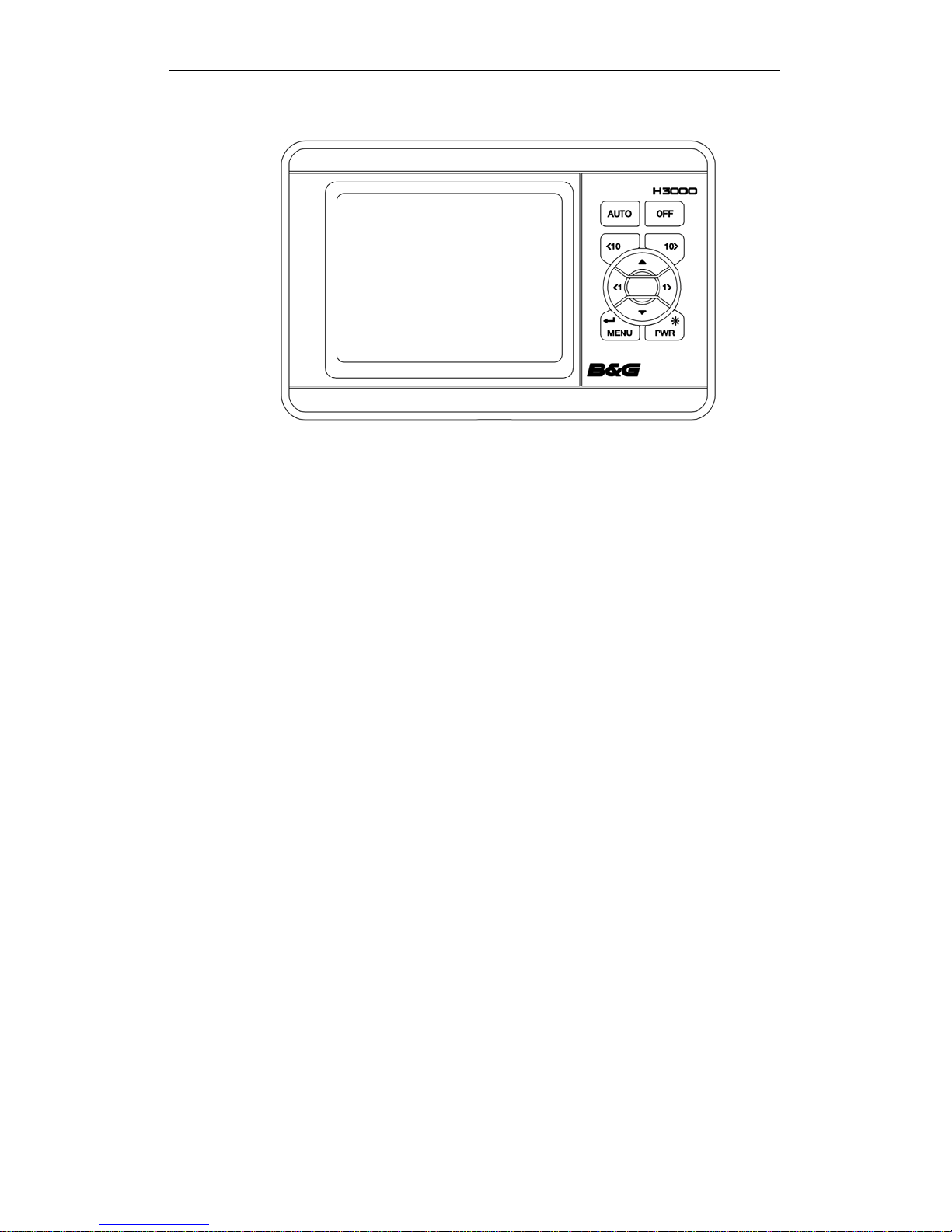
GRAPHICAL PILOT DISPLAY (GPD)
H3000 GPD – Graphical Pilot Display
The GPD utilises a high-resolution graphical display that allows the use of
a very intuitive user interface, and flexible data representation.
Monochrome and colour versions are available. The monochrome version
is intended for on-deck use and viewing from distance, the colour version
is designed to allow additional clarity in short-range applications such as
navigation stations, cabins, pedestal mounts etc
The GPD has a simple, easy to learn, user interface and keypad l ayout that
simplifies the operation and configuration of the system.
There are dedicated keys for direct Pilot control (Auto, Off, 10º port, and
10º starboard) as well as the menu navigation keys used on the GFD.
It is possible to display a number of user configurable instrument pages,
and access the main H3000 setup and control menus as per the GFD.
Index matched bonded display technology is used to give the dual benefits
of increased display clarity in all lighting conditions and complete
elimination of the possibility of condensation obscuring the display.
HB-3001-02
9
H3000 Pilot Handbook___________________________________________________
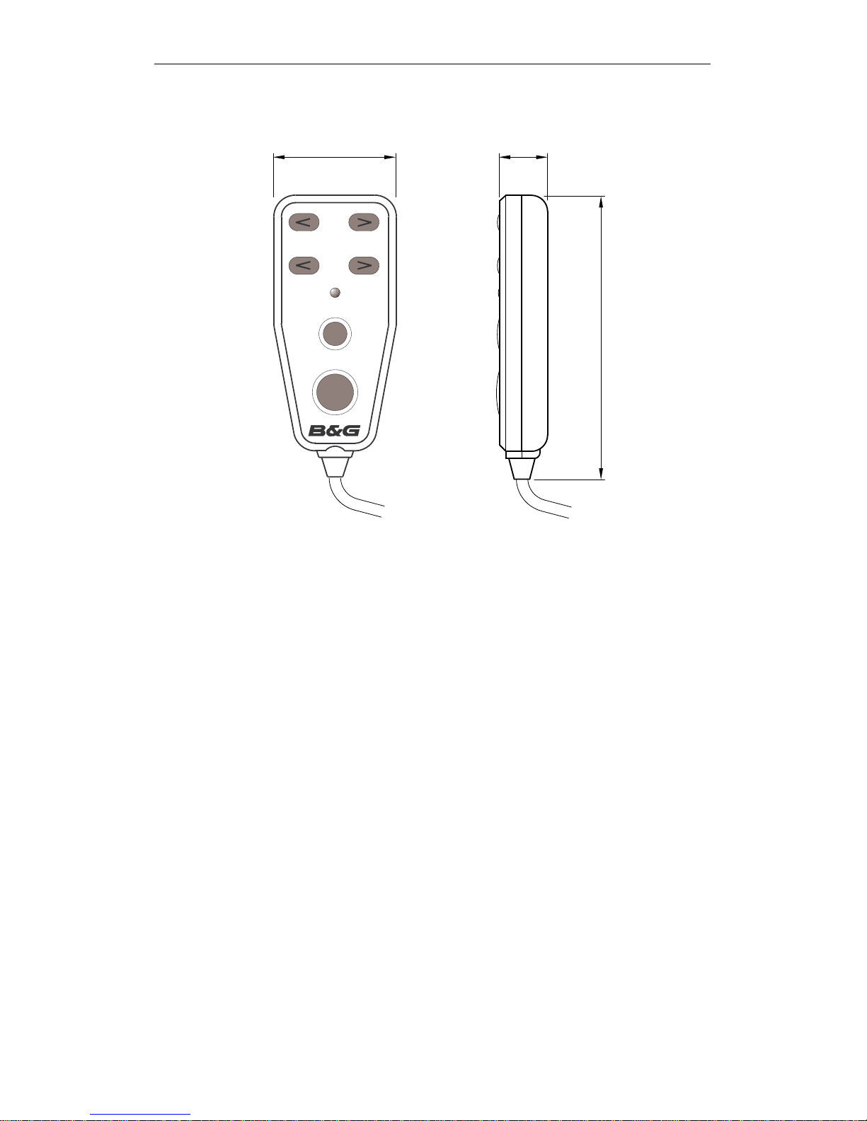
HAND-HELD CONTROLLER
56.5 24.0
10
1
auto/resume
128.0
off
Hand-held Controller
The Hand-held Controller provides a wired remote control of the H3000
Pilot. The six keys used for dedicated functions are as follows:
10 degree course change (Port/Starboard).
1 degree course change (Port/Starboard).
Auto/Resume - Pilot engage and return to course.
Off - Pilot disengage.
HB-3001-02
10
___________________________________________________H3000 Pilot Handbook
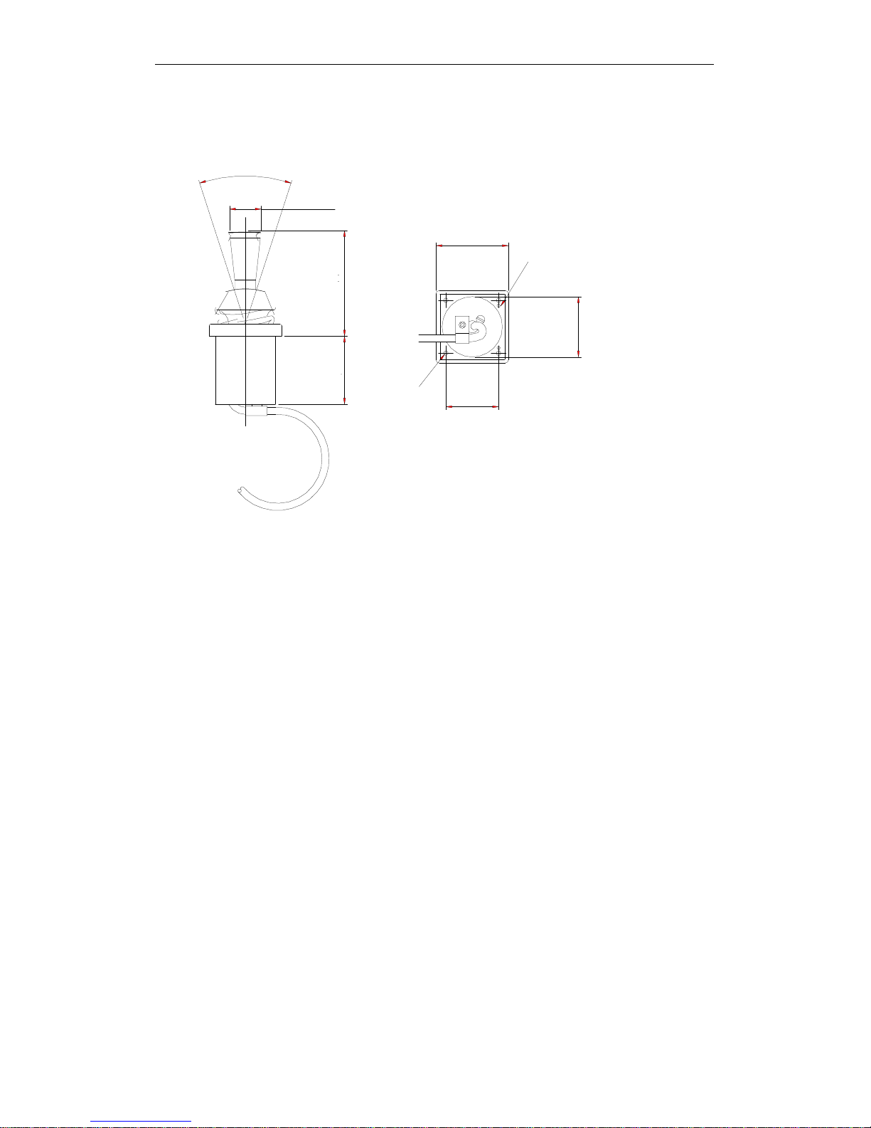
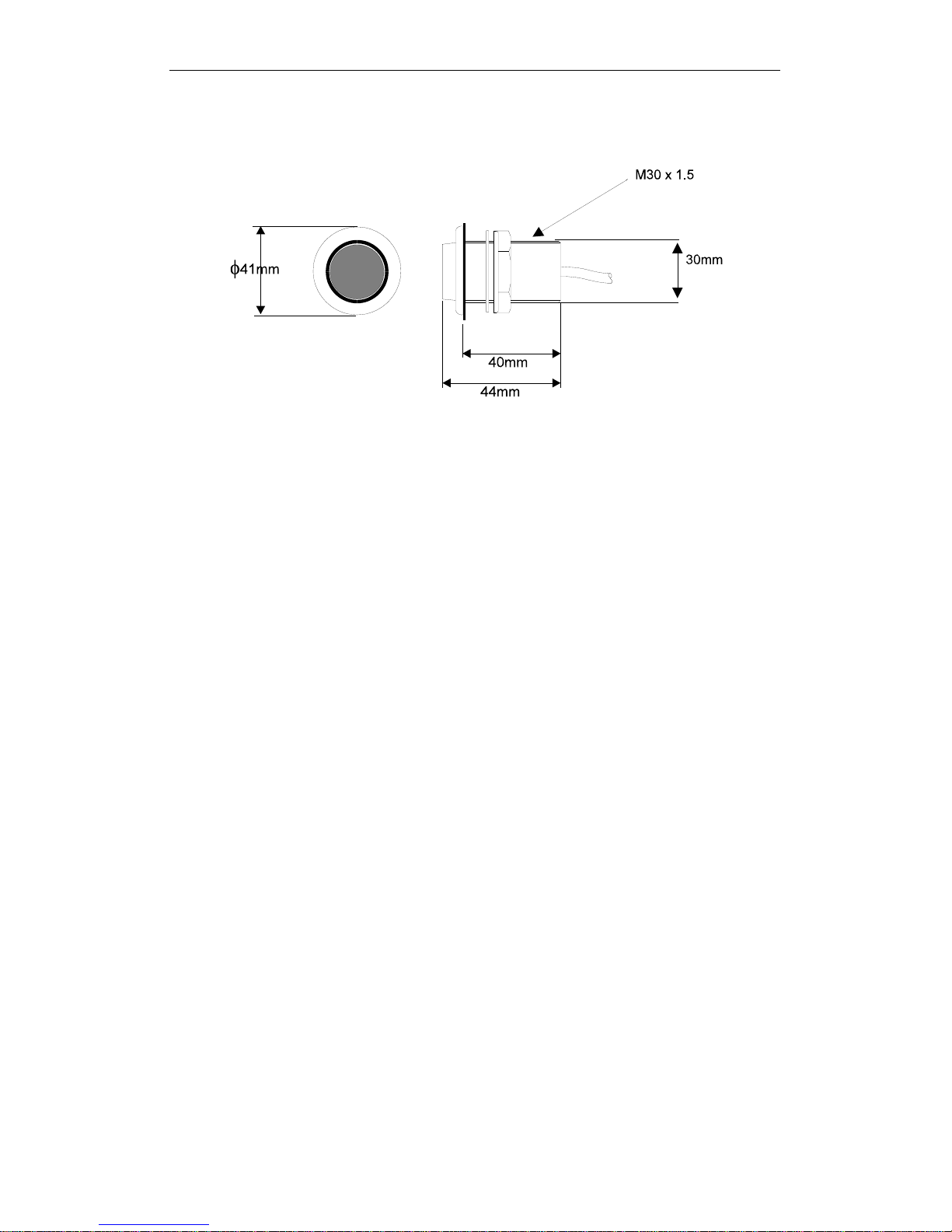
JOYSTICK
o
36.0
View from underside
dia 21.0 mm
48.0 mm
Forward indicator marks
70. 0 mm
dia 40.0 mm
45.0 mm
4 holes
dia 3.0 mm
35.0 mm
Joystick
The Joystick allows direct control of the rudder via the Pilot control
electronics. The unit is deck-mountable, allowing it to be used internal or
external steering positions. A 10m (30ft) 6-core screened cable connects
the unit directly into the ACP. Joystick steering is engaged and
disengaged with the separate red control button. The lever controls the
port and starboard movement of the rudder.
There are two modes of joystick operation available to the Helmsman,
these are as follows:
Normal Steering - The rudder moves in the direction of the Joystick.
When the Joystick is returned to the central position the rudder movement
stops. The greater the movement of the Joystick the faster the response of
the rudder.
Proportional Steering - The position of the rudder follows the position of
the Joystick. When the Joystick returns to the central position the rudder
returns to its initial position.
HB-3001-02
11
H3000 Pilot Handbook___________________________________________________
MAN OVERBOARD BUTTON
Man Overboard Button
The Man Overboard (MOB) button is an optional extra that activates the
Pilot's Man Overboard procedure to assist in the recovery of the person, or
persons, that may have been lost overboard.
The MOB facility will operate when the system has a valid source of boat
speed in use (not Manual Speed or SOG). It will function whether the
Pilot is engaged or not.
Two modes of operation are available, Manual Recovery and Automatic
Recovery.
Manual Recovery displays Range and Bearing to the MOB position on
the GPD, GFD and FFD displays to enable the crew to steer the boat back
to the MOB position. The range and bearing is calculated by dead
reckoning so tidal influences are effectively corrected for. If you have a
GPS MOB facility you should also activate this to store a geographic
MOB position. Manual recovery is available for both sailing and power
boats.
Automatic Recovery allows power boat users to follow the range &
bearing function with a request to the Pilot to carry out a Williamson turn
which will bring the boat back in the vicinity of the MOB position.
HB-3001-02
12

___________________________________________________H3000 Pilot Handbook
Manual Recovery procedure:
WARNING
This procedure is in addition to standard MOB practices, ensure that you
and your crew are familiar with normal MOB procedures.
1) Press the MOB button as soon as the person is lost overboard. The
alarm will sound (if fitted) and the displays will show the Man
Overboard message. The GFD, GPD and FFD displays will now
show the bearing and distance to the person overboard. On FFDs
the bearing will be flashed three times and then the distance (in
Nautical Miles) once, this pattern will repeat until cancelled.
2) Maintain a lookout and keep visual contact with the person in the
water. Steer the boat back to the person overboard following the
bearing and distance displays. The boat can be steered using the
course change buttons when the Pilot is engaged, or press the red
Off Key to disengage the Pilot and steer the boat manually.
Recover the person overboard.
3) To end the MOB sequence press and hold the MOB for 5 seconds.
The displays of bearing and distance are cancelled and the Pilot will
return to the normal (previous) setting. Alternatively select Silence
on a GFD or GPD alarm window, or click Enter twice on a FFD.
Automatic Recovery procedure:
WARNING
This procedure is in addition to standard MOB practices, ensure that you
and your crew are familiar with normal MOB procedures. If you are
unfamiliar or unsure of the Automatic Recovery mode do NOT use it, use
manual recovery and standard MOB practices instead.
1) Press the MOB button as soon as the person is lost overboard. The
alarm will sound (if fitted) and the displays will show the Man
Overboard message. The GFD, GPD and FFD displays will now
show the bearing and distance to the person overboard. On FFDs
the bearing will be flashed three times and then the distance (in
Nautical Miles) once, this pattern will repeat until cancelled.
HB-3001-02
13

H3000 Pilot Handbook___________________________________________________
2) Maintain a lookout and keep visual contact with the person in the
water. Reduce the boat speed to LESS THAN 8 knots. Ensure that
the area is clear of other boats and obstacles.
3) Press the MOB three times in quick succession to initiate an
Automatic Recovery. The Pilot will control the steering and execute
a Williamson Turn. AT ANY STAGE you may press the red Off
Key to disengage the Pilot and steer the boat manually. Recover
the person overboard.
4) To end the MOB sequence press and hold the MOB for 5 seconds.
The displays of bearing and distance are cancelled and the Pilot will
return to the normal (previous) setting. Alternatively select Silence
on a GFD or GPD alarm window, or click Enter twice on a FFD.
HB-3001-02
14

___________________________________________________H3000 Pilot Handbook
OPERATING INFORMATION
SWITCHING ON
The H3000 Pilot has two power supplies (instrument and heavy duty
rudder drive supply) these are normally connected via circuit breaker. The
Pilot computer and Pilot displays are powered via the Fastnet network
cable and share the same source of power supply as the H3000 instrument
system.
The hydraulic ram, rotary drive or hydraulic pump supplies are routed via
the Pilot computer. The heavy-duty supply is dedicated to the rudder drive
unit and is connected via a separate heavy-duty fuse or circuit breaker.
To switch the Pilot ON, proceed as follows:
Switch ON the instrument supplies.
Switch ON the heavy-duty power supply for the rudder drive unit.
The Pilot will only operate if both the heavy duty and instrument
supplies are switched ON.
Notes:
If the Pilot Display indicates Fault 115 when engaged for the first time,
check that the heavy-duty drive supply is switched ON. If it is off switch
ON the heavy-duty supply and clear the fault message.
If the Pilot Display shows Fault 104 when engaged, this indicates that
there is no boat speed input from the sensor. This is normal if the Pilot is
switched on at the dockside.
HB-3001-02
15
H3000 Pilot Handbook___________________________________________________
GETTING STARTED
GPD KEYS EXPLAINED
Power / Lights
To power on/off the H3000 system press and hold
the Power key until the unit powers up/powers
down. At start up the Pilot screen will be
displayed.
A Short press of the Power key will provide full
background illumination on all system displays.
Further short presses of the key decrease the
illumination in three stages from full brightness to
OFF. The next press of the key enables full
illumination.
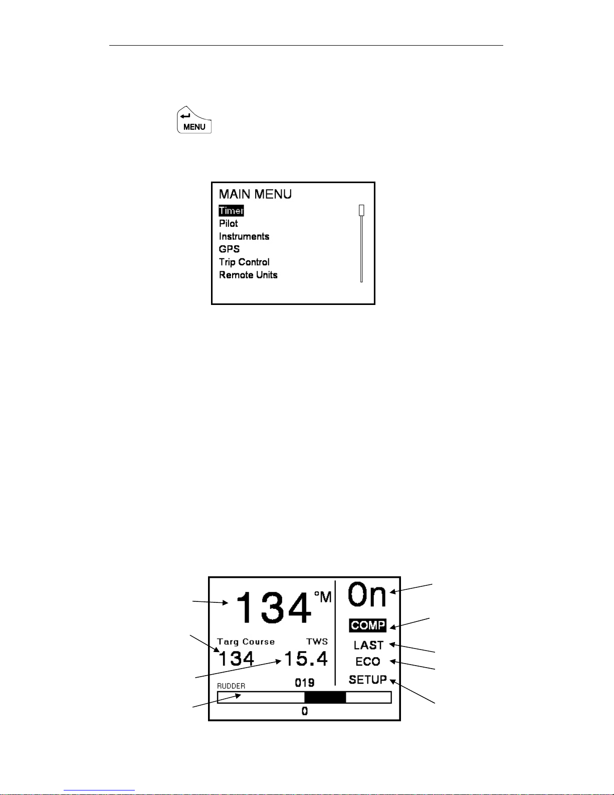
Menu / Enter
The Menu/Enter key either activates the main
menu or actions a menu item.
When the GPD is in compass mode NORMAL
pressing the menu key (MENU) will bring up the
main menu as shown on page 21
However if a menu item is highlighted the key
acts as an enter key to select the menu choice.
If editing a parameter this key also confirms the
new value.
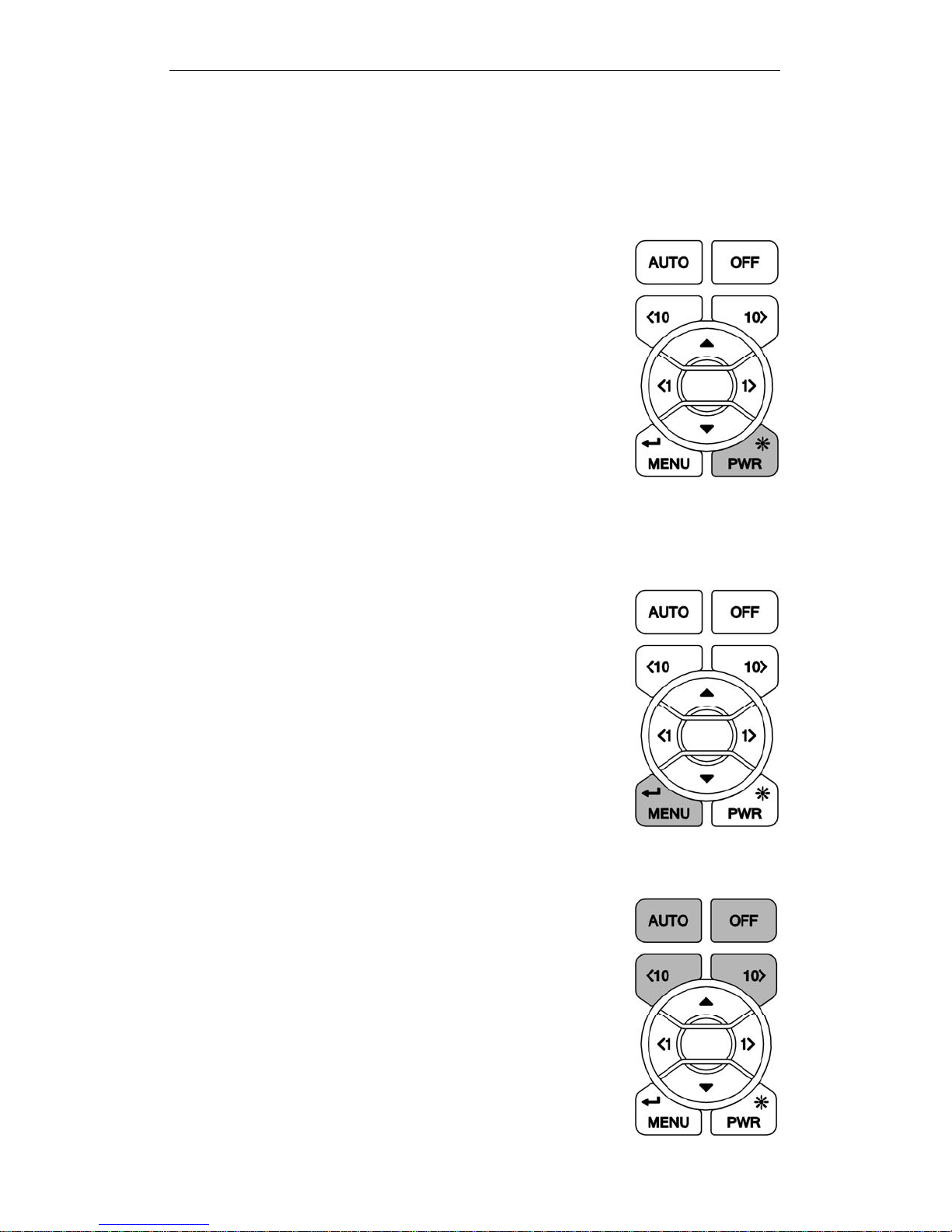
Pilot function keys
These are dedicated function keys that will
control the Pilot regardless of which menu you
are navigating.
Pressing one of these keys whilst in any menu
will bring up the Pilot screen and perform the
relevant function at the same time.
HB-3001-02
16

___________________________________________________H3000 Pilot Handbook
Auto: When the Pilot is in standby a single press engages the
Pilot. The Pilot screen will be displayed.
Off: (RED Button) When the Pilot is engaged a single press
disengages the Pilot. The Pilot screen will be displayed.
10º Port: This is a 10º degree dodge function that changes the
Pilot course by 10º Port.
The Pilot screen will be displayed.
10º Starboard: This is a 10º dodge function that changes the
Pilot course by 10º Starboard. The Pilot screen will be
displayed.
WARNING: Pressing the Auto key when the Pilot is disengaged will
engage the Pilot. Pressing the Off key when the Pilot is engaged will
disengage the Pilot. Be aware of your Pilot status before your use these
keys!
1º Keys
These function keys change the Pilot course by 1º
Port or 1ºStarboard as applicable. When in
compass mode you can use these keys to pre-set the
course.
When navigating menus they perform as left and
right action keys. Un this mode they do not affect
the Pilot course.
Up & Down
Navigate up and down within the Pilot screen and
standard menu modes.
HB-3001-02
17

H3000 Pilot Handbook___________________________________________________
GPD Menu Structure
The central concept to the operation of the GPD is the menu system; once
this is grasped operation very quickly becomes familiar.
The idea of structured layers of menus is seen everywhere in modern
software, and regular mobile phone or computer users should have a head
start.
The principle is that at any one level there is a set of choices that you can
scroll through until you find the one you want. Having found the correct
menu entry, it is then selected by pressing ↵ (or X key) the GPD then
displays the next menu down.
Here you again scroll through the available options until you find and
select your choice. In many cases this is as far as you will need to go, e.g.
to choose a function for display.
To complete some actions such as entering a calibration value, switching
on an alarm, and so on, you will need to navigate the GPD menus.
Throughout this handbook there are some standard formats used to assist
you.
Each menu choice selected will be in CAPITALS.
The page description / contents will be in lower case.
Indicates the menu key should be pressed to enter main menu
Indicates scroll right, to enter a sub menu
X
Indicates scroll left, to return to the previous menu
W
Indicates scroll down / Reduce value
T
Indicates scroll up / Increase value
S
Indicates press Enter to confirm an action
↵
Indicates 1º right
Indicates 1º left
Indicates Dodge 10º right
Indicates Dodge 10º left
HB-3001-02
18

___________________________________________________H3000 Pilot Handbook
At any time during the navigation of the GPD, press the key to
return to the Pilot screen, and engage the Pilot.
At any time during the navigation of the GPD, press the key to
return to the Pilot screen, and disengage the Pilot.
At any time during the navigation of the GPD, press the keys
to return to the Pilot screen. If the Pilot is engaged it will dodge 10º in the
direction that corresponds to the key press.
Example 1: Engaging the Pilot
At anytime whilst the Pilot is disengaged press to engage the Pilot.
The Pilot will steer the boat to the currently selected course for the mode
selected. e.g. in compass mode the current heading is selected as the
desired course. In WIND T mode the Pilot will steer to the current TWA
(True Wind Angle).
Example 2: Disengaging the Pilot
Press to disengage the Pilot. The Pilot will be switched off and
you will be required to take manual control of the wheel.
Example 3: To set a course from the Pilot screen
You must be on the Pilot screen and the Pilot must be engaged for you to
be able to utilise this function.
T Highlight SET COURSE ↵ ST Set the required course ↵
Example 4: To set an alarm function.
SETUP X ALARMS X Select Alarm XInput Value X Toggle
ON/OFF ↵
HB-3001-02
19

H3000 Pilot Handbook___________________________________________________
Example 5: Watch Alarm
The Pilot will sound an alarm (if an audible alarm is installed to the
Instrument system) and cause all the system displays to display a warning
at a pre-set time interval to keep the helmsman and crew alert. There are
two selections:
OFF: The alarm is disabled (default).
ON: 1 to 360 - A number is set in minutes. The alarm is enabled when
the value is entered.
To set-up WATCH alarm:
SETUP X ALARMS X WATCH X Using TS Set the
required time X Using TS turn on watch.
HB-3001-02
20
___________________________________________________H3000 Pilot Handbook
GPD MAIN MENU
Pressing the key will display the main menu.
Below is a list of the menu options, their functions, or setup information.
TIMER
The timer is designed as a start / elapsed timer; it will count up from zero
and will count down to zero if a time value is set.
TIMER X T
SYNC ↵ Jumps to the nearest whole minute. i.e. 4:45
or 5:07 both become 5:00
START ↵ Starts Timer
SET ↵ TS (Set countdown timer value) ↵ To timer menu.
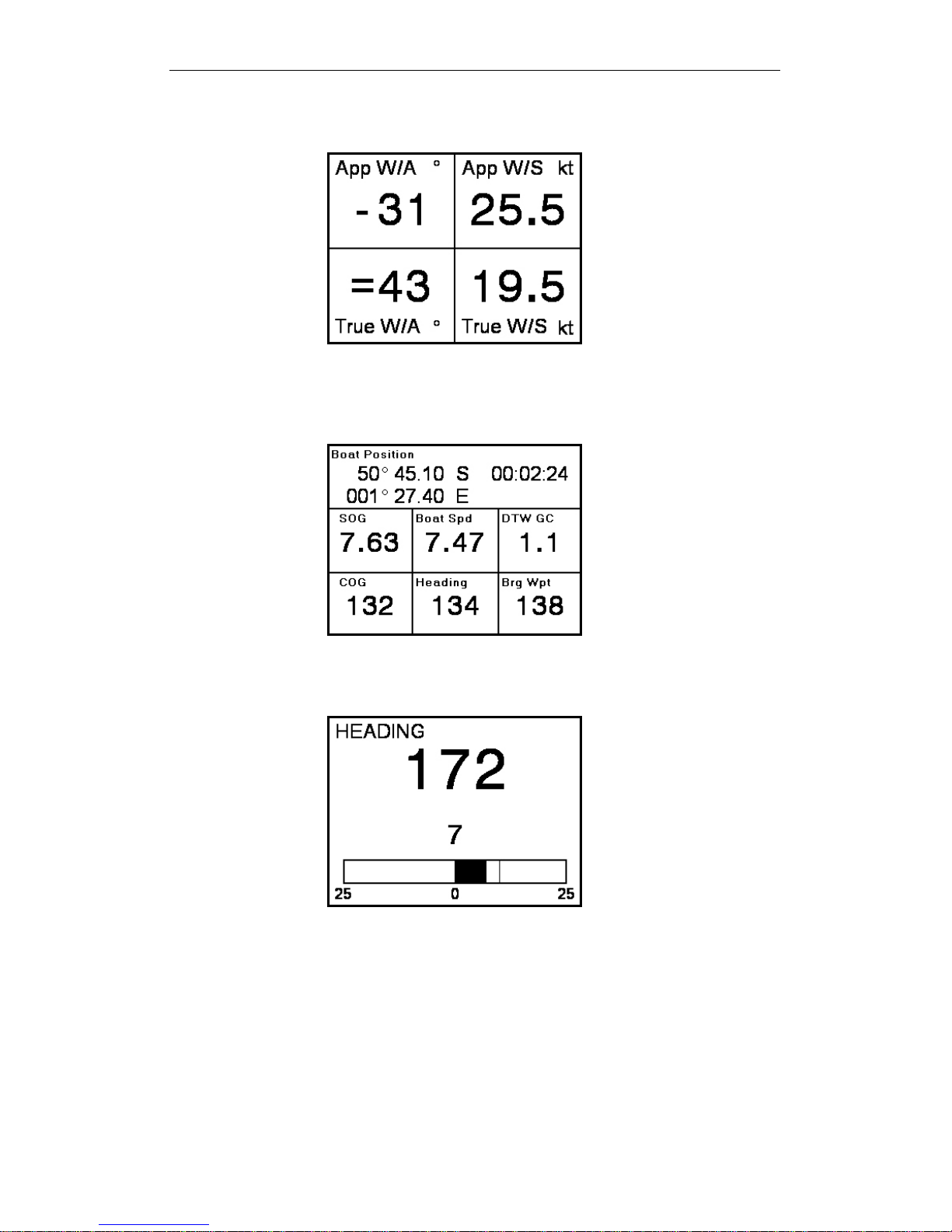
PILOT
Selecting Pilot will take you to the Pilot screen.
PILOT X Pilot Data Page
Pilot Status
Current Heading
Steering Mode
Pilot Target
Action
Instrument Data
Rudder Angle
HB-3001-02
Response Mode
Setup
21

H3000 Pilot Handbook___________________________________________________
Current Heading
• Current system Heading
Pilot Target
• Desired Course, Wind Angle, Bearing to Waypoint or Cross
Track Error.
Note: This will display different types of data determined by which
steering mode is selected.
Instrument Data
• Displays one item of data from the H3000 Instrument system.
TWS is the default but this can be changed to show any of the
H3000 systems instruments data.
Rudder Angle
• Graphic in 1-degree resolution, to Port or Starboard.
• Numeric value shown above graphic
Pilot Status "ON" or "OFF"
Can be controlled by the ON/OFF keys on Pilot display, or RemoteVision.
Steering Mode Indication
• COMP - Steer to Compass
• WINDA - Steer to Apparent Wind
• WINDT - Steer to True Wind
• NAV - Steer to Waypoint
• POLAR - Steer to Target TWA.
• POWER - Manual steering via the GPD Port & Starboard keys
Action
• Last – Last course –Option in COMP mode
• Next – Next waypoint – Option in NAV mode
• Tack – Tack on command – Option in WINDA & T modes
• Gybe – Gybe on command – Option in WINDA & T modes
• Mid – Return to mid position – Option in POWER mode
HB-3001-02
22

___________________________________________________H3000 Pilot Handbook
g
Response Mode
• ECON – Economy: The rudder movement is limited; this
reduces the overall consumption of the autopilot system.
• NORM – Normal course keeping and rudder response.
• DWIND – Downwind: More active steering control especially
for downwind steering in demanding conditions.
• PERF1
• PERF2
• PERF3
• PERF4
Performance. W hen a Gy ro Compass i s connected
you will have the performance option - PERF this
function has 4 levels that allow for manual
increase and decrease of steerin
response.
Note: ECON consumes the least amount of power when steering
the Pilot but offers the slowest response to the Pilot processors
information. PERF4 consumes the most power but has the highest
response time.
Setup shortcut
• Advanced Settings Menu.
Note: This menu can also be found via: MENU X SETUP X
COMMISSION X PILOT X ADVANCED SETTINGS
See Page 64 for Advanced Settings
HB-3001-02
23

H3000 Pilot Handbook___________________________________________________
INSTRUMENTS
There are six pre-set pages of instrument data.
INSTRUMENTS X
Use the
Page 1: Boat Speed - Velocity Made Good (VMG)
X key to step through each of the instrument pages.
X Page 2: Boat Speed - True Wind Angle
X Page 3: Timer, Boat Speed - True Wind Direction
HB-3001-02
24
___________________________________________________H3000 Pilot Handbook
X Page 4: Apparent Wind Angle - Apparent Wind Speed - True Wind Angle - True
Wind Speed
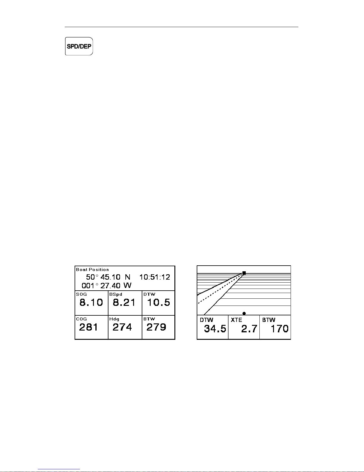
X Page 5: Boat Position – Speed Over Ground – Boat Speed – Distance to Waypoint
– Course Over Ground – Heading – Bearing to Waypoint - Local Time
X Page 6: Steering Compass Graphic
Displaying temporary information on any instrument page
It is possible to quickly access additional information from the instrument
pages, you can display this data by following the example below.
To change the display data whilst navigating the speed and depth pages.
HB-3001-02
25
H3000 Pilot Handbook___________________________________________________
Select the page you wish to temporarily change T
Highlight the data you wish to change ↵
Select the new data to be displayed ↵
Note: Any changes in configuration made to the current display page by
this method are not stored, the page will return to its previous
configuration when any other display page is selected. To permanently
change contents see page 37
GPS
There are two pages that show GP S data.
Page 1 shows nine pieces of data:
Boat Position – Speed Over ground – Boat Speed – Distance to Waypoint
– Course Over Ground – Heading – Bearing to Waypoint – Local Time
Page 2 has a rolling road with three pieces of data: Distance to Waypoint
– Cross Track Error – Bearing to Waypoint. Both shown below.
GPS X GPS Data Page 1 X GPS Data Page 2
X
Note: This Information relies on a suitable GPS interfaced to the H3000
via NMEA 0183, or the USB port.
HB-3001-02
26
___________________________________________________H3000 Pilot Handbook
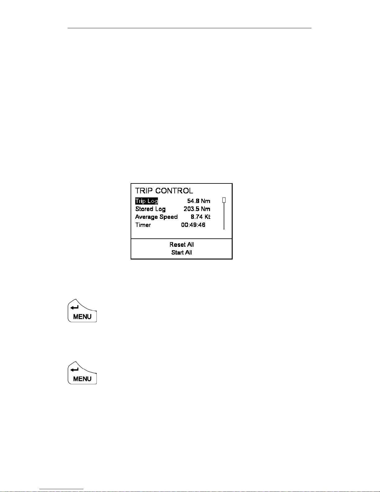
TRIP CONTROL
This page shows all trip functions in one menu including the stored log
that allows easy access to reset and start operations. The stored log is also
displayed but cannot be reset.
When any trip function is started, all other trip functions that have been
reset start simultaneously, except when the timer countdown is started.
Under this condition, the other functions start, again if previously reset,
when the countdown reaches zero.
This is designed for the beginning of races, so that you have DR, log and
timer running automatically, from the race start time.
Example 1: Reset Trip Log
TRIP CONTROL X Trip Log X T Reset ↵
Example 2: Start all trip functions.
TRIP CONTROL T Start All ↵
HB-3001-02
27
H3000 Pilot Handbook___________________________________________________
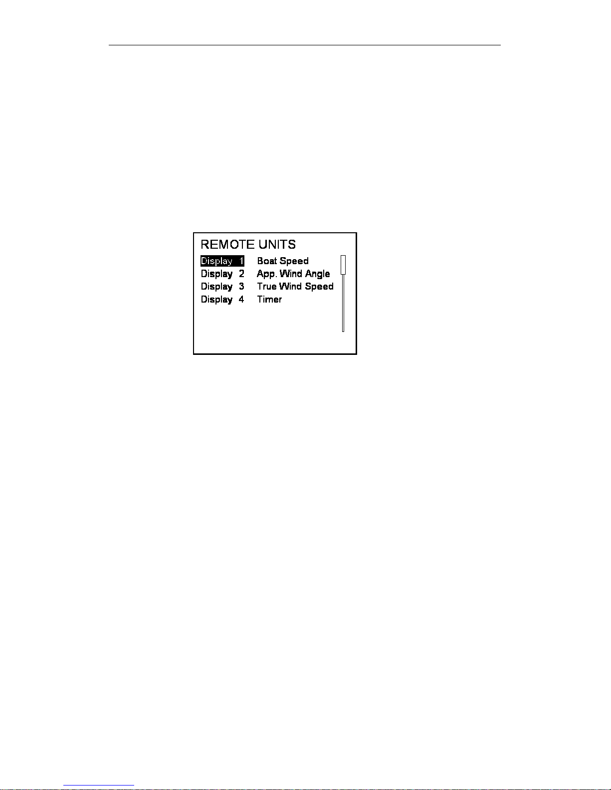
REMOTE UNITS
This option provides remote control of any 20/20 or 40/40 type display.
Below is an example of how to change the data shown on display 1.
REMOTE UNITS X Display 1 X Boat Speed TS Select one of the 14
preset data pages W Scroll left to save the new display data
Note: When a display is selected, as shown above, the remote display will
flash so you can identify the physical display unit you are controlling.
Below is an example of how to change any of the pre-set pages to display
alternative data.
REMOTE UNITS X Display 1 X Boat Speed ↵
This will display the data menu X Highlight the required piece of
data ↵ Will bring you back to the remote units page.
Note: The selected function data will then be stored in that particular
remote display’s preset page.
HB-3001-02
28
___________________________________________________H3000 Pilot Handbook
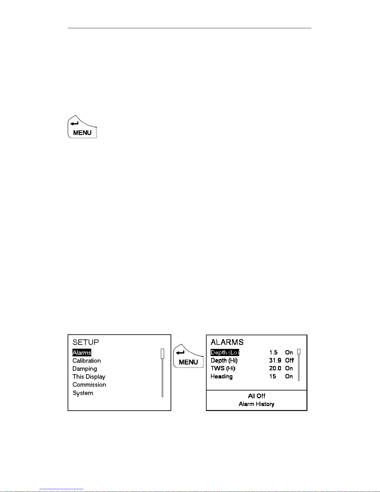
SETUP
The Setup menu provides access to system alarms, calibration, damping,
this display, and commissioning.
ALARMS
You can preset alarm parameters to trigger a warning when the set li mits
are reached. This will flash a message on the display to warn you. An
audible alarm can also be installed. Any user alarm can be switched on or
off.
SETUP X ALARMS
There are 3 types of alarm. Hi, Low and Sector. The sector alarm is
activated if you move outside a specified sector angle.
When an alarm is on and that alarm is triggered it will send a warning
message to all GPDs and GFDs. FFDs will flash with the function that
has triggered the alarm. If you select ignore then the alarm will not be
displayed on that individual unit, but will continue to be shown on all
other displays until silenced.
If you select ‘silent’ the warning screen will disappear on all displays.
The alarm will automatically become active again once you move back
within the alarm limits.
Each time the alarm zone is reached it will trigger the alar m. You must set
the alarm to off to deactivate it completely.
Note: All alarms can be turned off by highlighting ALL OFF in the
alarms menu and pressing ↵
HB-3001-02
or
X
29
H3000 Pilot Handbook___________________________________________________
Note: Only the common alarms are listed. For other available alarms go to
ALARMS X OTHER ALARMS
Example 1: Setting Depth Low Alarm
SETUP X ALARMS X Depth (Low) X Set TS Lo limit X Switch
TS On/Off
Example 2: Accessing Alarm History
SETUP X ALARMS X ALARM HISTORY ↵
Alarm History displays all alarms that have been triggered. This
information is cleared when the power is switched off.
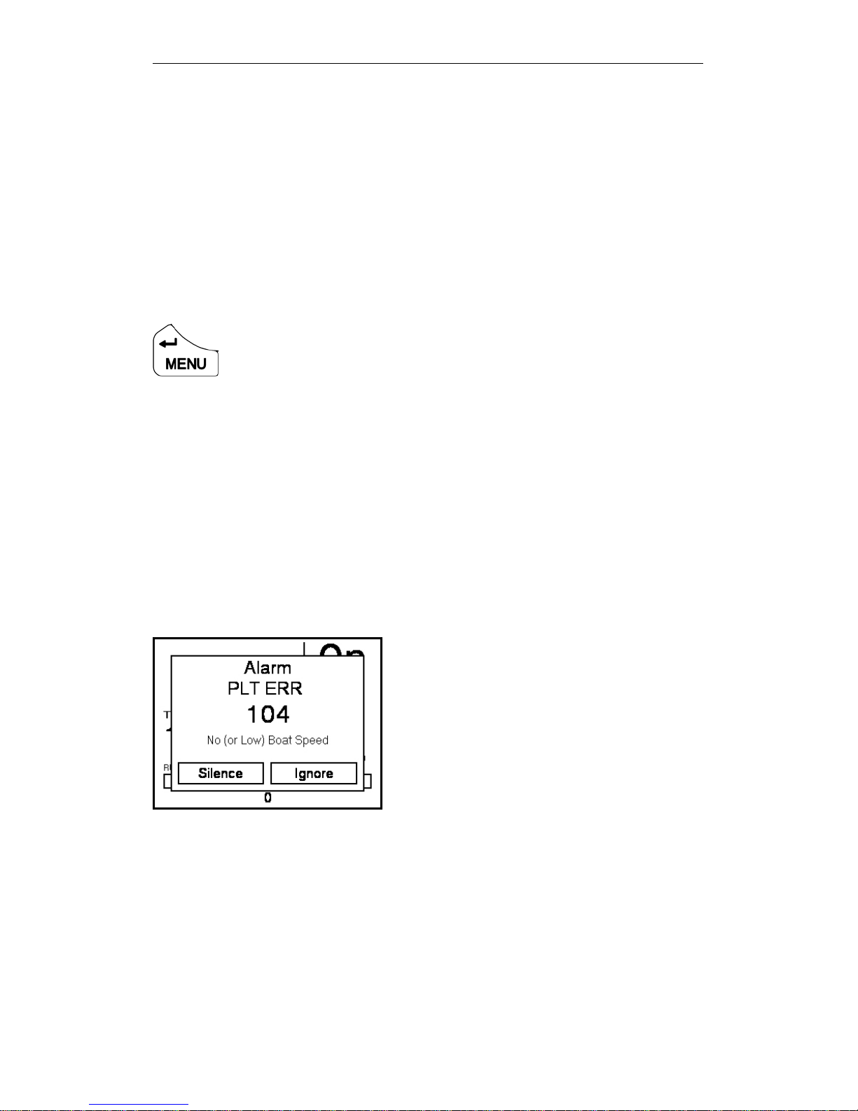
Example 3: No (or Low) Boat Speed Alarm
In the screen shot below the ‘No (or Low) Boat Speed’ Alarm is shown.
To accept and clear remove the alarm window globally from all GFDs
select SILENCE and press ↵, if you wish to remove this warning from
the display you are using select IGNORE and press ↵
HB-3001-02
30
T W SILENCE ↵
T X IGNORE ↵
 Loading...