

Page 1

www.bandg.com
Page 2

Page 3

H3000 Pilot Handbook
CONTENTS
B&G
Notication ........................................................................................................ 7
Liability and Safety Warnings ........................................................................... 8
About B&G ....................................................................................................... 9
About this Handbook ........................................................................................ 9
SYSTEM INTRODUCTION
H3000 System Example .................................................................................. 11
H3000 Pilot ACP ............................................................................................. 12
Graphical Pilot Display (GPD) ....................................................................... 13
Hand-Held Controller ...................................................................................... 14
Joystick ............................................................................................................ 15
Man Overboard Button .................................................................................... 16
OPERATING INFORMATION
Switching On ................................................................................................... 20
GETTING STARTED
Graphic display (GPD) Keys Explained ......................................................... 21
GPD Menu Structure ....................................................................................... 24
GPD MAIN MENU
Timer ............................................................................................................... 27
Pilot ................................................................................................................. 27
Instruments ...................................................................................................... 30
GPS ................................................................................................................. 32
Trip Control .................................................................................................... 33
Remote Units ................................................................................................... 34
Setup ................................................................................................................ 35
Alarms ....................................................................................................... 35
Calibration ................................................................................................. 37
Compass Calibration.................................................................................. 37
Halcyon 2000 Compass Calibration .......................................................... 38
Halcyon Gyro Compass Calibration and Setup ......................................... 39
Heading Source Selection .......................................................................... 40
Damping .......................................................................................................... 40
Dynamic Damping ..................................................................................... 40
This Display .................................................................................................... 42
Page Setup ................................................................................................ 42
Screen ........................................................................................................ 43
HB-3001-03
3
Page 4

H3000 Pilot Handbook
Show Alarms on this Display ....................................................................43
Favourites .................................................................................................. 44
Units........................................................................................................... 45
Unit Information ........................................................................................ 46
Key Lock ................................................................................................... 46
Commission ..................................................................................................... 46
Use SOG as Speed Input ........................................................................... 46
Heading ...................................................................................................... 47
Pilot ............................................................................................................ 47
System ....................................................................................................... 48
PILOT OPERATION
Engaging the Pilot ........................................................................................... 49
Dis-Engaging the Pilot .................................................................................... 49
Changing the Pilot Course............................................................................... 49
Pilot Mode Selection ....................................................................................... 50
Steer to Compass ....................................................................................... 50
Steer to Apparent Wind Angle ................................................................... 51
Steer to True Wind Angle .......................................................................... 51
Steer to Waypoint ...................................................................................... 51
Steer to Target TWA .................................................................................. 53
Power ......................................................................................................... 53
Response Mode ............................................................................................... 54
Response Mode: Halcyon Gyro-Stabilised Compass ................................ 54
Response Mode: Halcyon 2000 Compass or Other Sources ..................... 54
Action .............................................................................................................. 55
COMMISSIONING
Pilot Installation Check List ............................................................................ 60
Drive Unit and Steering System ................................................................ 60
Hydraulic Rams ......................................................................................... 60
Hydraulic Pumps ....................................................................................... 61
Rotary Drives ............................................................................................. 61
Compass Installation.................................................................................. 62
Electronics Installation .............................................................................. 62
Parameters to be Set .................................................................................. 63
Pilot Commission ............................................................................................ 64
Dockside Setup .......................................................................................... 64
Sea Trial...........................................................................................................68
Checking Rudder Gain Learning ............................................................... 69
Setting the Rudder Gain Manually ............................................................ 69
Setting the Rudder Gain Value .................................................................. 70
4
HB-3001-03
Page 5

H3000 Pilot Handbook
Checking the Boat Lag .............................................................................. 71
Boat Lag Response .................................................................................... 71
Setting the Boat Lag Value ........................................................................ 72
Advanced Settings ........................................................................................... 72
Speed Source ............................................................................................. 73
Automatic Response .................................................................................. 73
Recovery Mode ............................................................................ ............ 74
Nav Source ................................................................................................ 75
Magnetic Dip Zone .................................................................................... 76
Pilot Speed Cal .......................................................................................... 77
Setting the Speed Calibration Value .......................................................... 78
Joystick Type ............................................................................................. 78
Boat Length ............................................................................................... 79
Rudder Max Angle.....................................................................................79
Watch Alarm Lock ..................................................................................... 79
INSTALLATION INFORMATION
Cable and Connection Information ................................................................. 80
General Wiring Notes ................................................................................80
Pilot Drive Unit Cables.............................................................................. 81
Network Installation ........................................................................................ 82
Pilot Display Connections ............................................................................... 84
ACP Unit Terminal Details ............................................................................. 85
Clutch Voltage Selection ............................................................................86
DIP Switch Location .................................................................................. 87
ACP Wiring Connections ................................................................................ 88
Network & Alarm ...................................................................................... 88
Man Overboard Button & Hand-held Controller ...................................... 89
Remote Button & Joystick ......................................................................... 90
Hydraulic Ram Drives ............................................................................... 91
Rotary Drives ............................................................................................. 92
Stern Drives ............................................................................................... 93
Proportional Solenoid ................................................................................ 94
Continuous Drives ..................................................................................... 95
Linear Feedback ........................................................................................ 96
Halcyon 2000 Compass ............................................................................. 97
Halcyon Gyro Stabilised Compass ............................................................ 98
Direct Speed Input ..................................................................................... 99
Direct Speed Input ................................................................................... 100
Rotary Rudder Reference Sensor .................................................................. 101
Installation of RRF .................................................................................. 101
Typical System with Tiller Arm and Quadrant ........................................ 102
HB-3001-03
5
Page 6

H3000 Pilot Handbook
Steering System Orientation .................................................................... 103
RRF Position............................................................................................ 104
Drag-Link & RRF Position...................................................................... 104
Linear Feed Back Unit ............................................................................. 105
Diagnostic Data
Fault Diagnosis .............................................................................................. 107
6
HB-3001-03
Page 7

H3000 Pilot Handbook
B&G
NOTIFICATION
The information contained in this document is subject to change without prior
notice.
Navico UK Ltd. shall not be liable for errors contained herein or for incidental or
consequential damages in connection with the furnishing, performance or use of
this document.
No part of this work covered by the copyright hereon may be reproduced or
otherwise copied without prior permission from Navico UK Ltd.
© 2008 Navico UK Ltd. All rights reserved.
HB-3001-03
Navico UK Ltd.
Premier Way, Abbey Park,
Romsey, SO51 9DH,
United Kingdom
Tel: +44 1794 518448
Fax: +44 1794 518077
www.bandg.com
email: sales@bandg.com
email: support@bandg.com
7
Page 8

H3000 Pilot Handbook
LIABILITY AND SAFETY WARNINGS
Navico UK Limited accept no responsibility for the use and/or operation of this
equipment. It is the user’s responsibility to ensure that under all circumstances the
equipment is used for the purposes for which it has been designed.
Warning: Electrical Hazard
This equipment uses high voltage electrical power. Contact with high voltages may result in
injury and/or loss of life.
Warning: Calibration
The safe operation of this equipment is dependent on accurate and correct calibration.
Incorrect calibration of this equipment may lead to false and inaccurate navigational readings
placing the yacht into danger.
Warning: Operational Hazard
The H3000 system is an Electronic Navigation aid and is designed to assist in the navigation
of your yacht. It is not designed to totally replace conventional navigation procedures and
precautions and all necessary precautions should be taken to ensure that the yacht is not
placed into danger.
The Pilot is an aid to steering the vessel. It is the users responsibility to ensure the safe
control and movement of the vessel at all times.
Caution: Electrical Supply
This equipment is designed for use with a power supply source of 12V dc. The application
of any other power supply may result in permanent damage to the equipment.
Caution: Cleaning
The use of alcohol or solvent-based cleaners will damage this equipment and any warranty
in force will be invalidated.
Caution: Display Installation
Displays installed into locations manufactured from conductive materials (e.g. Steel, Carbon
Fibre etc.) should be insulated from the structure to prevent damage to the casings as a result
of the effects of electrolysis.
Caution: Processor Installation
All B&G Processors should be installed below decks in a dry location protected from water
and moisture.
Power Off Disclaimer
When in standby mode the H3000 system continues to consume power. To conserve the
vessel’s battery life switch off power at the main breaker.
8
HB-3001-03
Page 9

H3000 Pilot Handbook
ABOUT B&G
B&G has welcomed the constant challenge to develop new electronic solutions
for every sailor’s need. Harnessing technical developments and providing proven
solutions has continued to be the focus that keeps B&G on the leading edge of
advanced marine electronics.
Proven in the world's most testing environments, B&G offers the most accurate
and reliable systems used by blue water cruisers, single-handed racers and record
breakers alike rmly establishing ourselves as one of the leading innovators of the
most highly advanced marine electronics. B&G is renowned for tried and trusted
solutions and is ever evolving to offer the best technology to the customer.
B&G’s Promise.
“Uncompromising performance, precision and reliability from both our
products and our people”.
ABOUT THIS HANDBOOK
Instructions in this handbook describe the controls and calibration of your H3000
Pilot system. You can also use the controls on the RemoteVision.
All functions described in this handbook refer to the standard Hydra processor
settings unless indicated with a Hercules logo as shown below.
HERCULES
Indicates that the information listed relates to Hercules
processor functionality which includes Hydra functions.
Indicates that the information listed relates to Performance
PERFORM
processor functionality which includes Hercules and Hydra
functions.
Please contact your local dealer if you wish to upgrade your processor. A list of
B&G approved dealers can be found at www.bandg.com
HB-3001-03
9
Page 10

H3000 Pilot Handbook
SYSTEM INTRODUCTION
The H3000 Pilot fully integrates with the H3000 instrument system, both in terms
of style and performance. The instrument system transmits sensor information via
the B&G Fastnet network to the ACP Pilot computer unit.
The Pilot computer processes the sensor data and then sends signals to the rudder
drive system (linear ram, rotary drive or hydraulic pump) to steer the vessel on the
desired course. The complex learning algorithms used in the Pilot computer ensure
that the steering performance is optimised for the sea and weather conditions, and
quickly responds to any changes that may occur.
Control of the Pilot is via the keys on any one of the dedicated Graphical Pilot
Displays (GPD). Each display acts as a master allowing control of the Pilot from
any station.
H3000 Pilots are available with a wide range of powerful and reliable 12V or 24V
dc rudder drive units suitable for boats of over 7m (23ft). The ACP (Advanced
Control Program) Pilot computers are supplied in two specications ACP1 or
ACP2 (Advanced Control Programming) depending on the size of vessel, power
requirements and options in use.
The H3000 Pilot can be used for both sailing and power boats that have a H3000
System installed.
10
HB-3001-03
Page 11
H3000 Pilot Handbook
GFDGPD
Analogue
Displays
Barometric
Pressure & Air
Temperature
Sensor
ACP 2 Pilot
Processor
3-Axis Gyro
Stabilised
Compass
Halcyon
2000
Compass
Wireless
Port
Remote
Vision
Vertical
Masthead
Unit
20/20
Displays
H3000 CPU
Hercules
Performance
Pilot Drive Unit
Rudder
Reference Unit
Speed & Depth
Sensors
12 / 24 V
12 V
NMEA In / Out
12 V
USB
10/10
Displays
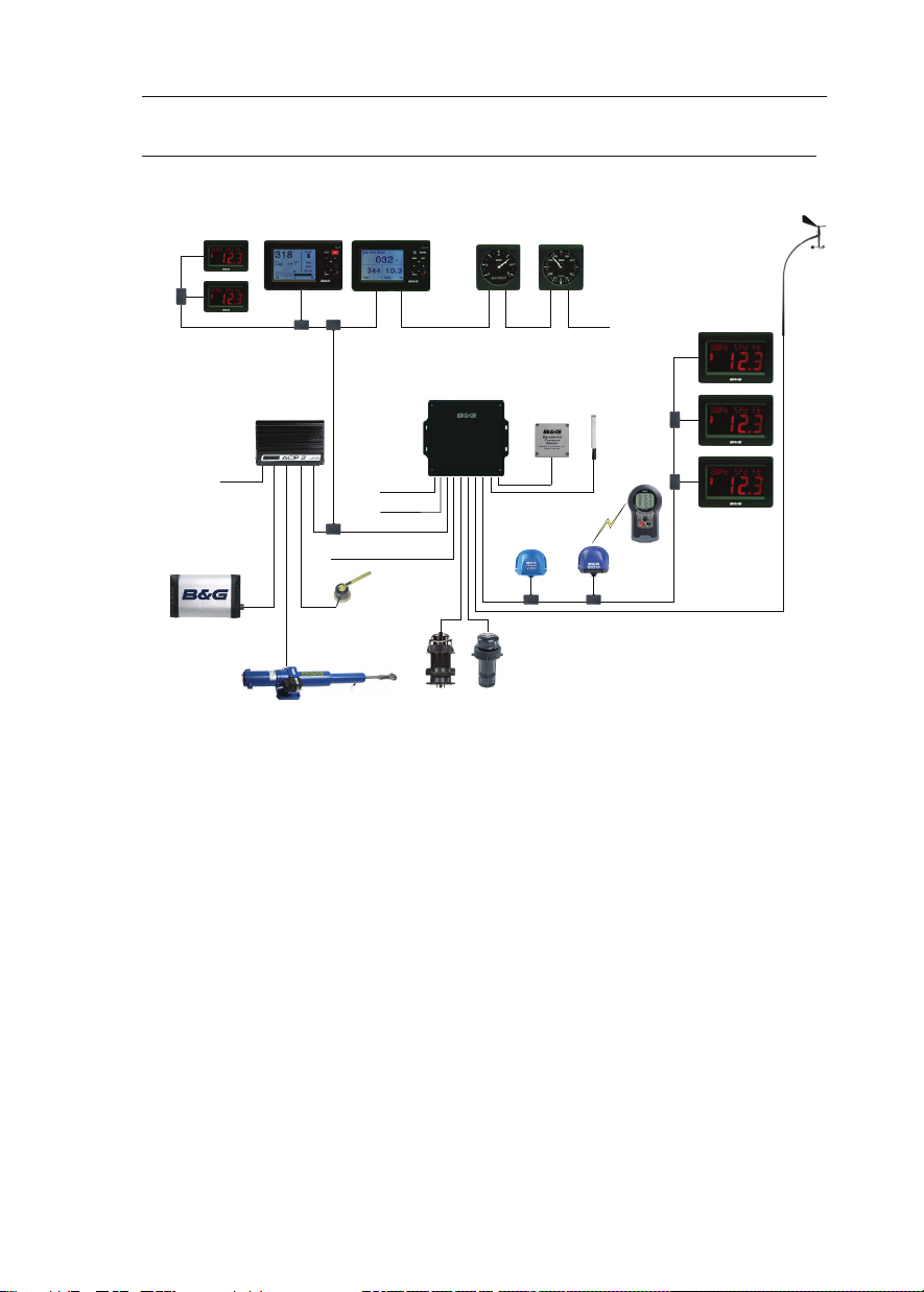
H3000 SYSTEM EXAMPLE
H3000 System example with Pilot Processor H3000 ACP
Above is an example of a typical H3000 system. At the centre of the system is the
Central Processor Unit (CPU).
All sensor information is fed back to the CPU and can be easily controlled and
congured via the Graphical Function Display (GFD).
The ACP Pilot processor integrates with the CPU to optimise the performance of
the B&G system providing data for the autopilot to steer the boat.
HB-3001-03
11
Page 12
H3000 Pilot Handbook
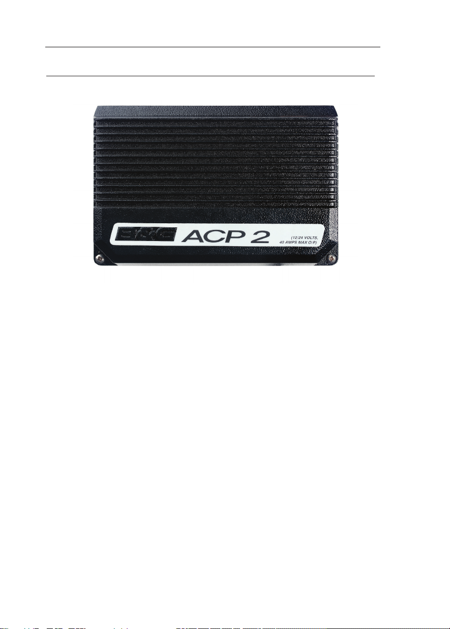
H3000 PILOT ACP
The B&G H3000 Pilot Processor has been proven in the world's most testing
environments.
Used by bluewater cruisers, single handed sailors and record breakers alike
the ACP takes on the role of an extra crew member who never tires and can be
called upon 24 hours a day to take control of your boat and sail it in your desired
direction.
• The ACP can be set to:
• Steer to compass
• Steer to Apparent or True wind angle
• Steer to waypoint
• Power steer mode (Enables you to manually steer the pilot via the Graphical
Pilot Display (GPD)
The Pilot offers smart tack & gybe,.enhansed response and recovery features
as well as auto response for optimum course keeping. (requires Halcyon GyroStabilised Compass (HGSC)
12
HB-3001-03
Page 13
H3000 Pilot Handbook
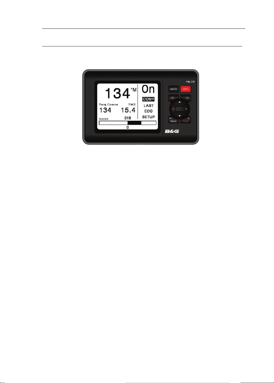
GRAPHICAL PILOT DISPLAY (GPD)
The GPD utilises a high-resolution graphical display that allows the use of a very
intuitive user interface, and exible data representation.
Monochrome and colour versions are available. The monochrome version is
intended for on-deck use and viewing from distance, the colour version is designed
to allow additional clarity in short-range applications such as navigation stations,
cabins, pedestal mounts etc
The GPD has a simple, easy to learn, user interface and keypad layout that simplies
the operation and conguration of the system.
There are dedicated keys for direct Pilot control (Auto, Off, 10º port, and 10º
starboard) as well as the menu navigation keys used on the GFD.
It is possible to display a number of user congurable instrument pages, and access
the main H3000 setup and control menus as per the GFD.
Index matched bonded display technology is used to give the dual benets of
increased display clarity in all lighting conditions and complete elimination of the
possibility of condensation obscuring the display.
HB-3001-03
13
Page 14
H3000 Pilot Handbook
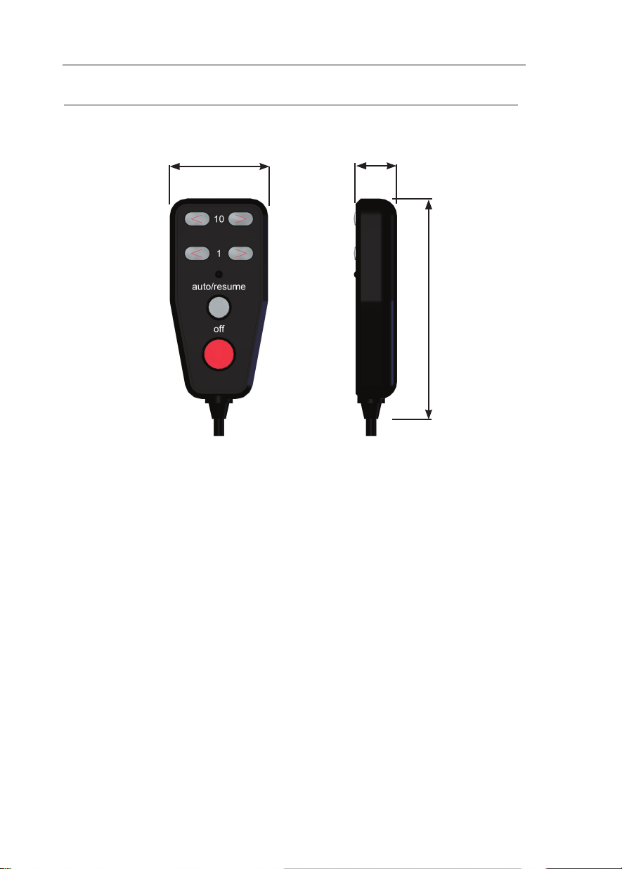
HAND-HELD CONTROLLER
56.5 mm
24.0 mm
128.0 mm
The Hand-held Controller provides a wired remote control of the H3000 Pilot. The
six keys used for dedicated functions are as follows:
• 10 degree course change (Port/Starboard)
• 1 degree course change (Port/Starboard).
• Auto/Resume - Pilot engage and return to course.
• Off - Pilot disengage.
14
HB-3001-03
Page 15
H3000 Pilot Handbook
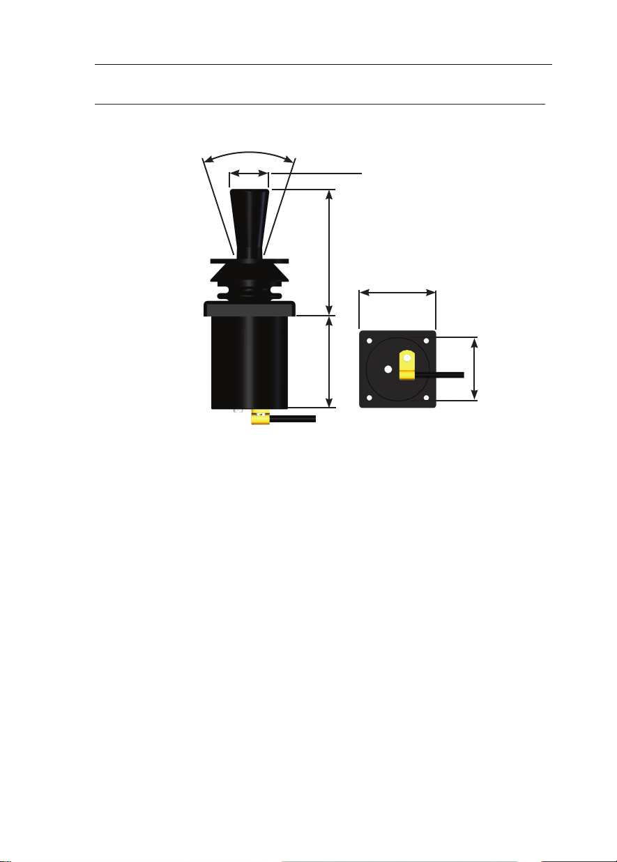
JOYSTICK
36.0 º
ø 21.0 mm
70.0 mm
48.0 mm
45.0 mm
ø 40.0 mm
The Joystick allows direct control of the rudder via the Pilot control electronics.
The unit is deck-mountable, allowing it to be used internal or external steering
positions. A 10m (30ft) 6-core screened cable connects the unit directly into the
ACP. Joystick steering is engaged and disengaged with the separate red control
button. The lever controls the port and starboard movement of the rudder.
There are two modes of joystick operation available to the Helmsman, these are as
follows:
Normal Steering ~ The rudder moves in the direction of the Joystick. When the
Joystick is returned to the central position the rudder movement stops. The greater
the movement of the Joystick the faster the response of the rudder.
Proportional Steering ~ The position of the rudder follows the position of the
Joystick. When the Joystick returns to the central position the rudder returns to its
initial position.
HB-3001-03
15
Page 16
H3000 Pilot Handbook
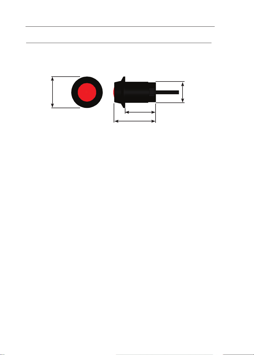
MAN OVERBOARD BUTTON
Ø 41 mm
30 mm
40 mm
44 mm
The Man Overboard (MOB) button is an optional extra that activates the Pilot’s
Man Overboard procedure to assist in the recovery of the person, or persons, that
may have been lost overboard.
The MOB facility will operate when the system has a valid source of boat speed
in use (not Manual Speed or SOG). It will function whether the Pilot is engaged
or not.
Two modes of operation are available, Manual Recovery and Automatic
Recovery.
Manual Recovery ~ Displays Range and Bearing to the MOB position on the
GPD, GFD and FFD displays to enable the crew to steer the boat back to the MOB
position. The range and bearing is calculated by dead reckoning so tidal inuences
are effectively corrected for.
If you have a GPS MOB facility you should also activate this to store a geographic
MOB position. Manual recovery is available for both sailing and power boats.
Automatic Recovery ~ Allows power boat users to follow the range & bearing
function with a request to the Pilot to carry out a Williamson turn which will bring
the boat back in the vicinity of the MOB position.
16
HB-3001-03
Page 17

H3000 Pilot Handbook
Manual Recovery procedure:
WARNING
This procedure is in addition to standard MOB practices, ensure that you and your
crew are familiar with normal MOB procedures.
1) Press the MOB button as soon as the person is lost overboard. The alarm
will sound (if tted) and the displays will show the Man Overboard message.
The GFD, GPD and FFD displays will now show the bearing and distance to
the person overboard. On FFDs the bearing will be ashed three times and
then the distance (in Nautical Miles) once, this pattern will repeat until
cancelled.
2) Maintain a lookout and keep visual contact with the person in the water. Steer
the boat back to the person overboard following the bearing and distance
displays. The boat can be steered using the course change buttons when the
Pilot is engaged, or press the red Off Key to disengage the Pilot and steer the
boat manually. Recover the person overboard.
3) To end the MOB sequence press and hold the MOB for 5 seconds. The
displays of bearing and distance are cancelled and the Pilot will return to the
normal (previous) setting. Alternatively select Silence on a GFD or GPD
alarm window, or click Enter twice on a FFD.
Automatic Recovery procedure:
WARNING
This procedure is in addition to standard MOB practices, ensure that you and your
crew are familiar with normal MOB procedures. If you are unfamiliar or unsure of
the Automatic Recovery mode do NOT use it, use manual recovery and standard
MOB practices instead.
1) Press the MOB button as soon as the person is lost overboard. The alarm will
sound (if tted) and the displays will show the Man Overboard message. The
GFD, GPD and FFD displays will now show the bearing and distance to the
person overboard.
On FFDs the bearing will be ashed three times and then the distance (in
Nautical Miles) once, this pattern will repeat until cancelled.
HB-3001-03
17
Page 18

H3000 Pilot Handbook
2) Maintain a lookout and keep visual contact with the person in the water.
Reduce the boat speed to less than 8 knots. Ensure that the area is clear of
other boats and obstacles.
3) Press the MOB three times in quick succession to initiate an Automatic
Recovery. The Pilot will control the steering and execute a Williamson Turn.
AT ANY STAGE you may press the red Off Key to disengage the Pilot and
steer the boat manually. Recover the person overboard.
4) To end the MOB sequence press and hold the MOB for 5 seconds. The
displays of bearing and distance are cancelled and the Pilot will return to the
normal (previous) setting. Alternatively select Silence on a GFD or GPD
alarm window, or click Enter twice on a FFD.
18
HB-3001-03
Page 19

H3000 Pilot Handbook
OPERATING INFORMATION
SWITCHING ON
The H3000 Pilot has two power supplies (instrument and heavy duty rudder drive
supply) these are normally connected via circuit breaker. The Pilot computer and
Pilot displays are powered via the Fastnet network cable and share the same source
of power supply as the H3000 instrument system.
The hydraulic ram, rotary drive or hydraulic pump supplies are routed via the
Pilot computer. The heavy-duty supply is dedicated to the rudder drive unit and is
connected via a separate heavy-duty fuse or circuit breaker.
To switch the Pilot ON, proceed as follows:
• Switch ON the instrument supplies.
• Switch ON the heavy-duty power supply for the rudder drive unit.
The Pilot will only operate if both the heavy duty and instrument supplies are
switched ON.
Notes:
• If the Pilot Display indicates Fault 115 when engaged for the rst time, check
that the heavy-duty drive supply is switched ON. If it is off switch ON the
heavy-duty supply and clear the fault message.
• If the Pilot Display shows Fault 104 when engaged, this indicates that there is
no boat speed input from the sensor. This is normal if the Pilot is switched on
at the dockside.
HB-3001-03
19
Page 20
H3000 Pilot Handbook
GETTING STARTED
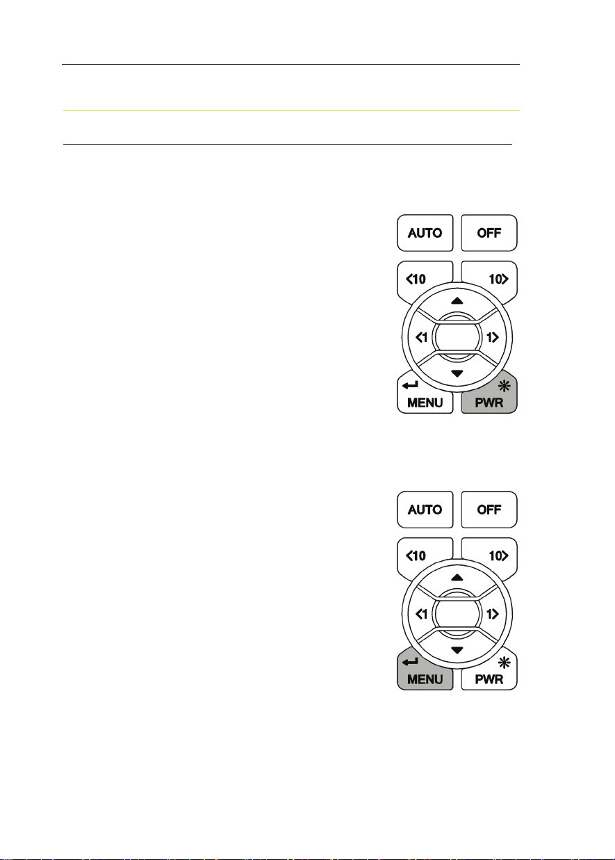
GRAPHIC DISPLAY (GPD) KEYS EXPLAINED
Power / Lights
To power on/off the GFD press and hold the Power
key until the unit powers up/powers down. At start
up the last page used on the previous operation will
be displayed.
A Short press of the Power key will provide full
background illumination on all system displays.
Further short presses of the key decrease the
illumination in three stages from full brightness
to OFF. The next press of the key enables full
illumination. Display lighting can be localised so
that the level is adjustable for individual displays.
Menu / Enter
The Menu/Enter key either activates the main menu
or actions a menu item.
When the GPD is in compass mode NORMAL
pressing the menu key (MENU) will bring up the
main menu as shown on page 21
However if a menu item is highlighted the key acts
as an enter key to select the menu choice.
If editing a parameter this key also conrms the
new value.
20
HB-3001-03
Page 21
H3000 Pilot Handbook
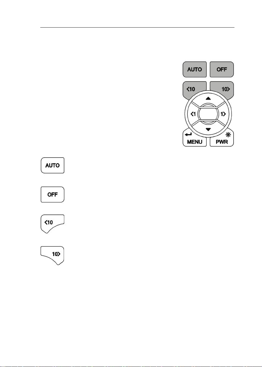
Pilot function keys
These are dedicated function keys that will
control the Pilot regardless of which menu you are
navigating.
Pressing one of these keys whilst in any menu will
bring up the Pilot screen and perform the relevant
function at the same time.
Auto: When the Pilot is in standby a single press engages the Pilot.
The Pilot screen will be displayed.
Off: (RED Button) When the Pilot is engaged a single press
disengages the Pilot. The Pilot screen will be displayed.
10º Port: This is a 10º degree dodge function that changes the Pilot
course by 10º Port.
The Pilot screen will be displayed.
10º Starboard: This is a 10º dodge function that changes the Pilot
course by 10º Starboard. The Pilot screen will be displayed.
WARNING ~ Pressing the Auto key when the Pilot is disengaged will engage the
Pilot. Pressing the Off key when the Pilot is engaged will disengage the Pilot. Be
aware of your Pilot status before your use these keys!
HB-3001-03
21
Page 22
H3000 Pilot Handbook
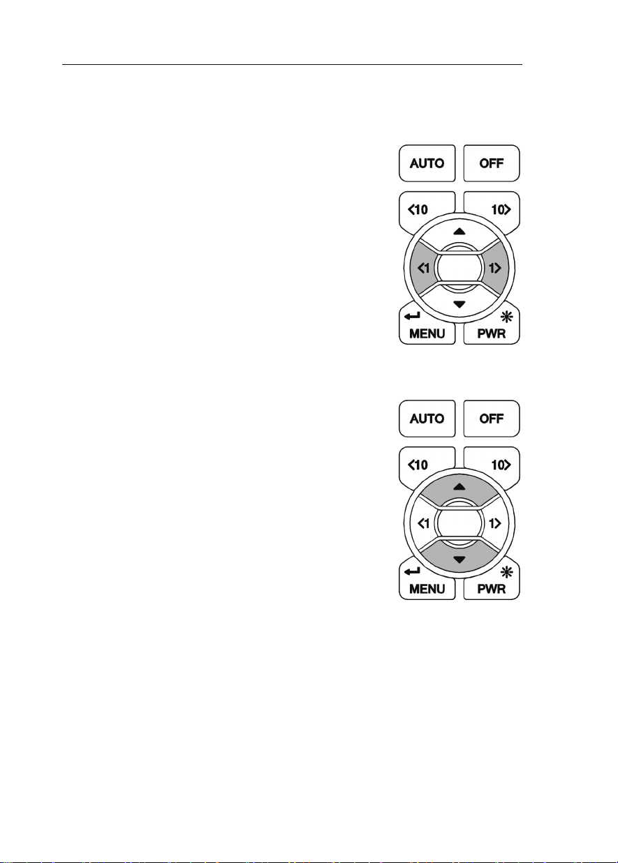
1º Keys
These function keys change the Pilot course by 1º
Port or 1ºStarboard as applicable. When in compass
mode you can use these keys to pre-set the course.
When navigating menus they perform as left and
right action keys. Un this mode they do not affect
the Pilot course.
Up & Down
Navigate up and down within the Pilot screen and
standard menu modes.
22
HB-3001-03
Page 23

H3000 Pilot Handbook
GPD MENU STRUCTURE
The central concept to the operation of the GPD is the menu system; once this is
grasped operation very quickly becomes familiar. The idea of structured layers
of menus is seen everywhere in modern software, and regular mobile phone or
computer users should have a head start.
The principle is that at any one level there is a set of choices that you can scroll
through until you nd the one you want. Having found the correct menu entry, it
is then selected by pressing ↵ (or key) the GPD then displays the next menu
down.
Here you again scroll through the available options until you nd and select your
choice. In many cases this is as far as you will need to go, e.g. to choose a function
for display. To complete some actions such as entering a calibration value, switching
on an alarm, and so on, you will need to navigate the GPD menus. Throughout this
handbook there are some standard formats used to assist you.
Each menu choice selected will be in CAPITALS. The page description / contents
will be in lower case.
Indicates the menu key should be pressed to enter Main Menu
Indicates scroll right, to enter a sub menu
Indicates scroll left, to return to the previous menu
Indicates scroll down / Reduce value
Indicates scroll up / Increase value
↵ IndicatespressEntertoconrmanaction
Indicates 1º right
Indicates 1º left
Indicates dodge 10º right
Indicates dodge 10º left
HB-3001-03
23
Page 24

H3000 Pilot Handbook
At any time during the navigation of the GPD, press the key to return to the
Pilot screen, and engage the Pilot.
At any time during the navigation of the GPD, press the key to return to the
Pilot screen, and disengage the Pilot.
At any time during the navigation of the GPD, press the keys to
return to the Pilot screen. If the Pilot is engaged it will dodge 10º in the direction
that corresponds to the key press.
Example 1 ~ Engaging the Pilot
At anytime whilst the Pilot is disengaged press to engage the Pilot. The
Pilot will steer the boat to the currently selected course for the mode selected. e.g.
in compass mode the current heading is selected as the desired course. In WIND T
mode the Pilot will steer to the current TWA (True Wind Angle).
Example 2 ~ Disengaging the Pilot
Press to disengage the Pilot. The Pilot will be switched off and you will be
required to take manual control of the wheel.
Example 3 ~ To set a course from the Pilot screen
You must be on the Pilot screen and the Pilot must be engaged for you to be able
to utilise this function.
Highlight SET COURSE ↵ Set the required course ↵
Example 4 ~ To set an alarm function.
SETUP ALARMS Select Alarm Input Value Toggle ON/OFF ↵
24
HB-3001-03
Page 25

H3000 Pilot Handbook
Example 5 ~ Watch Alarm
The Pilot will sound an alarm (if an audible alarm is installed to the Instrument
system) and cause all the system displays to display a warning at a pre-set time
interval to keep the helmsman and crew alert. There are two selections:
OFF: The alarm is disabled (default).
ON: 1 to 360 - A number is set in minutes. The alarm is enabled when the value
is entered.
To set-up WATCH alarm:
SETUP ALARMS WATCH Using Set the required time Using
turn on watch.
HB-3001-03
25
Page 26
H3000 Pilot Handbook
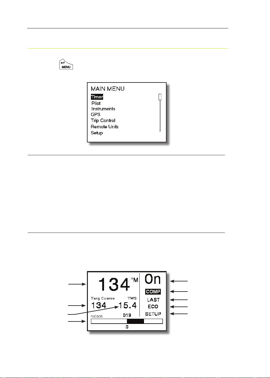
GPD MAIN MENU
Pressing the key will display the main menu.
Below is a list of the menu options, their functions, or setup information.
TIMER
The timer is designed as a start / elapsed timer; it will count up from zero and will
count down to zero if a time value is set.
TIMER
SYNC ↵ Jumps to the nearest whole minute. i.e. 4:45
or 5:07 both become 5:00
START ↵ Starts Timer
SET ↵ (Set countdown timer value) ↵ To timer menu
PILOT
Selecting Pilot will take you to the Pilot screen.
PILOT Pilot Data Page
Current Heading
Pilot Target
Instrument Data
Rudder Angle
26
Pilot Status
Steering Mode
Action
Response Mode
Setup
HB-3001-03
Page 27

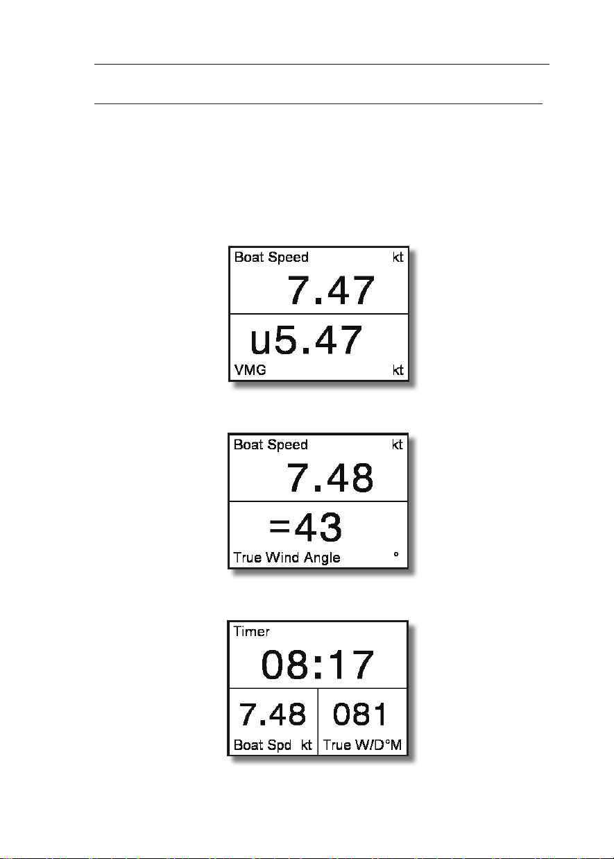
H3000 Pilot Handbook
Current Heading
• Current system Heading
Pilot Target
• Desired Course, Wind Angle, Bearing to Waypoint or Cross Track Error.
Note: This will display different types of data determined by which steering mode
is selected.
Instrument Data
• Displays one item of data from the H3000 Instrument system. TWS is
the default but this can be changed to show any of the H3000 systems
instruments data.
Rudder Angle
• Graphic in 1-degree resolution, to Port or Starboard.
• Numeric value shown above graphic
Pilot Status "ON" or "OFF"
Can be controlled by the ON/OFF keys on Pilot display, or RemoteVision.
Steering Mode Indication
• COMP - Steer to Compass
• WINDA - Steer to Apparent Wind
• WINDT - Steer to True Wind
• NAV - Steer to Waypoint
• POLAR - Steer to Target TWA.
• POWER - Manual steering via the GPD Port & Starboard keys
Action
• Last – Last course –Option in COMP mode
• Next – Next waypoint – Option in NAV mode
• Tack – Tack on command – Option in WINDA & T modes
• Gybe – Gybe on command – Option in WINDA & T modes
• Mid – Return to mid position – Option in POWER mode
HB-3001-03
27
Page 28

H3000 Pilot Handbook
Response Mode
• ECON – Economy: The rudder movement is limited; this reduces the
overall consumption of the autopilot system.
• NORM – Normal course keeping and rudder response.
• DWIND – Downwind: More active steering control especially for
downwind steering in demanding conditions.
• PERF1
• PERF2
• PERF3
• PERF4
Note: ECON consumes the least amount of power when steering the Pilot but
offers the slowest response to the Pilot processors information. PERF4 consumes
the most power but has the highest response time.
Setup shortcut
• Advanced Settings Menu.
This menu can also be found via: MENU SETUP COMMISSION PILOT
ADVANCED SETTINGS
See Page 64 for Advanced Settings
28
HB-3001-03
Page 29
H3000 Pilot Handbook
INSTRUMENTS
There are six pre-set pages of instrument data.
INSTRUMENTS
Use the key to step through each of the instrument pages.
Page 1: Boat Speed - Velocity Made Good (VMG)
Page 2: Boat Speed - True Wind Angle
Page 3: Timer, Boat Speed - True Wind Direction
HB-3001-03
29
Page 30
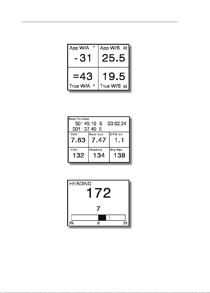
H3000 Pilot Handbook
Page 4: Apparent Wind Angle - Apparent Wind Speed - True Wind Angle True Wind Speed
Page 5: Boat Position – Speed Over Ground – Boat Speed – Distance to
Waypoint – Course Over Ground – Heading – Bearing to Waypoint - Local
Time
Page 6: Steering Compass Graphic
Displaying temporary information on any instrument page
It is possible to quickly access additional information from the instrument pages,
you can display this data by following the example below.
To change the display data whilst navigating the instrument pages,
30
HB-3001-03
Page 31

H3000 Pilot Handbook
Select the page you wish to temporarily change
Highlight the data you wish to change ↵
Select the new data to be displayed ↵
Note: Any changes in con guration made to the current display page by this
method are not stored, the page will return to its previous con guration when any
other display page is selected. To permanently change contents see page 37
GPS
There are two pages that show GPS data.
Page 1 shows nine pieces of data:
Boat Position – Speed Over ground – Boat Speed – Distance to Waypoint – Course
Over Ground – Heading – Bearing to Waypoint – Local Time
Page 2 has a rolling road with three pieces of data: Distance to Waypoint – Cross
Track Error – Bearing to Waypoint. Both shown below.
GPS GPS Data Page 1 GPS Data Page 2
Note: This Information relies on a suitable GPS interfaced to the H3000 via
NMEA 0183, or the USB port.
HB-3001-03
31
Page 32

H3000 Pilot Handbook
TRIP CONTROL
This page shows all trip functions in one menu including the stored log that allows
easy access to reset and start operations. The stored log is also displayed but cannot
be reset.
When any trip function is started, all other trip functions that have been reset start
simultaneously, except when the timer countdown is started. Under this condition,
the other functions start, again if previously reset, when the countdown reaches
zero.
This is designed for the beginning of races, so that you have DR, log and timer
running automatically, from the race start time.
Example 1 ~ Reset Trip Log
TRIP CONTROL Trip Log Reset ↵
Example 2 ~ Start all trip functions.
TRIP CONTROL Start All ↵
32
HB-3001-03
Page 33

H3000 Pilot Handbook
REMOTE UNITS
This option provides remote control of any 20/20 or 40/40 type display.
Below is an example of how to change the data shown on display 1.
REMOTE UNITS Display 1 Boat Speed Select one of the 14 preset
data pages Scroll left to save the new display data
Note: When a display is selected, as shown above, the remote display will fl ash so
you can identify the physical display unit you are controlling.
Below is an example of how to change any of the pre-set pages to display alternative
data.
REMOTE UNITS Display 1 Boat Speed ↵
This will display the data menu Highlight the required piece of data
↵ Will bring you back to the remote units page.
Note: The selected function data will then be stored in that particular remote
display’s preset page.
HB-3001-03
33
Page 34

H3000 Pilot Handbook
SETUP
The Setup menu provides access to system alarms, calibration, damping, this
display, and commissioning.
Alarms
SETUP ALARMS
You can preset alarm parameters to trigger a warning when the set limits are
reached. This will ash a message on the display to warn you. An audible alarm
can also be installed. Any user alarm can be switched on or off.
There are 3 types of alarm. Hi, Low and Sector. The sector alarm is activated if you
move outside a speci ed sector angle.
When an alarm is on and that alarm is triggered it will send a warning message to
all GPDs and GFDs. FFDs will ash with the function that has triggered the alarm.
If you select ignore then the alarm will not be displayed on that individual unit, but
will continue to be shown on all other displays until silenced.
If you select ‘silent’ the warning screen will disappear on all displays.
The alarm will automatically become active again once you move back within the
alarm limits.
Each time the alarm zone is reached it will trigger the alarm. You must set the alarm
to off to deactivate it completely.
Note: All alarms can be turned off by highlighting ALL OFF in the alarms menu
and pressing ↵
34
HB-3001-03
Page 35

H3000 Pilot Handbook
Note: Only the common alarms are listed. For other available alarms go to
ALARMS OTHER ALARMS
Example 1 ~ Setting Depth Low Alarm
SETUP ALARMS Depth (Low) Set Lo limit Switch On/Off
Example 2 ~ Accessing Alarm History
SETUP ALARMS ALARM HISTORY ↵
Alarm History displays all alarms that have been triggered. This information is
cleared when the power is switched off.
Example 3 ~ No (or Low) Boat Speed Alarm
In the screen shot below the ‘No (or Low) Boat Speed’ Alarm is shown. To accept
and clear remove the alarm window globally from all GFDs select SILENCE and
press ↵, if you wish to remove this warning from the display you are using select
IGNORE and press ↵
HB-3001-03
SILENCE ↵
IGNORE ↵
35
Page 36

H3000 Pilot Handbook
Calibration
SETUP CALIBRATION
It cannot be over stressed how important it is to calibrate the system properly, in
both the initial stages of the installation and operation, and throughout the life of
the system.
Calibration is an ongoing process and is something you must be aware of each
time you go sailing. This is particularly relevant of the true wind calibration, where
constant re ning will pay huge dividends in accuracy.
To this end the process has been simpli ed as far as possible, so that all you require
for accurate instrument data is some background knowledge together with a few
simple techniques.
Note: Information regarding calibrating your H3000 system can be found in the
H3000 Instrument Handbook.
Compass Calibration
B&G's Autoswing compasses contain software that allows them to record the
magnetic elds in the yacht that are causing deviation errors. It calculates the
corrections when the COMP CAL function is started and provided the following
conditions are met: -
The 360º turn - Halcyon 2000 and Halcyon Gyro Stabilised Compass is completed
in the same direction.
The rate of change of heading does not exceed 3°/s; i.e. the turn should take about
3 minutes to complete.
36
HB-3001-03
Page 37

H3000 Pilot Handbook
The rate of change of heading must not fall below 0.2 of a degree per second during
the 360° turn, i.e. the turn must not take longer than 12 minutes.
The rate of change in heading is reasonably constant.
The compass is installed in a location a safe distance from magnetic interference
such as iron keels, engines, loudspeakers etc.
Consideration should also be given to electrical cables which may carry high
currents (e.g. large motors).
The compass is installed in a location as close to the centreline of the boat as
possible. Avoid areas such as the fore peak and the sides of the hull where the
effects of pitch and roll are at their greatest.
On steel hulled vessels, the compass will need to be installed above decks away
from the effects of the hull.
Halcyon 2000 Compass Calibration
Check for any magnetic devices placed near the compass, especially ones that are
out of their normal places.
On a calm day select a stretch of open water with little trafc (so you will not have
to take avoiding action which would affect the calibration). The atter the water
and the less the wind the easier it will be to meet the conditions for calibration.
Check for and avoid sailing close to any large steel structures nearby, that may
cause additional, erratic deviations.
Now select:-
SETUP COMMISSION START COMPASS SWING
The display will now show the degrees of turn completed so far. When the full 360
deg turn has completed within the limits described earlier, the display should say
“PASS” to indicate a successful swing.
HB-3001-03
37
Page 38

H3000 Pilot Handbook
A “FAIL” indication suggest that the turn was not completed within the guidelines
or quite possibly that there is too great a magnetic inuence close to the sensor.
This will require investigation before the swing process is retried.
Now the swing is complete its important to eliminate any constant error in heading
due to the physical alignment of the sensor relative to the fore / aft line of the
boat.
This is normally checked for by using shore-based transits, once the error is known
it can be eliminated by entering the value into the system under:
SETUP CALIBRATION HEADING SET OFFSET VALUE (Enter new
value) ↵
For example, the compass was reading 320º and it should read 316º, then the value
to enter would be –4º from the current set value
Note: The rst time the system is switched on, or after a system reset, the Heading
will alternate with CAL. This is to indicate to the user that the compass must be
calibrated. This will disappear after the compass has been swung correctly.
Halcyon Gyro Compass Calibration and Setup
This section describes the setup and calibration of the Halcyon Gyro compass
connected to the H3000 system via the Halcyon Gyro Processor unit.
The conditions and preparations for performing an Auto swing are the same as
described in the previous section for the Halcyon 2000 Compass.
Once ready to start the swing select:-
SETUP CALIBRATION OTHER CALIBRATION MISC HALCYON
START (Set value to 1 starts swing) ↵
The display will now show the degrees of turn completed so far. When the full 360
deg turn has completed within the limits described earlier, the display should say,
“PASS” to indicate a successful swing.
A “FAIL” indication suggest that the turn was not completed within the guidelines
or quite possibly that there is too great a magnetic inuence close to the sensor.
This will require investigation before the swing process is retried.
38
HB-3001-03
Page 39

H3000 Pilot Handbook
Now the swing is complete its important to eliminate any constant error in heading
due to the physical alignment of the sensor relative to the fore / aft line of the
boat.
This is normally checked for by using shore-based transits, once the error is known
it can be eliminated by entering the value into the system under:
SETUP CALIBRATION HEADING SET OFFSET VALUE (Enter new
value) ↵
For example, the compass was reading 320 degrees and it should read 316, then the
value to enter would be –4 from the current set value
Heading Source Selection
The H3000 System can accept heading data from a variety of different sources.
These different sources are known as Nodes and allow the system to identify which
heading devices are connected to the system.
DAMPING
SETUP DAMPING
Another important facility that you need to be constantly aware of is the damping
available on certain functions. This allows you to lter signal noise on the function
when in unstable or rough conditions.
The damping works by applying a lter over a time period; the more you increase
this time period, the smoother the data readings will be, but the longer it will take
to see the effect of any change. Similarly the lower the time period the greater the
jumps you will see in the numbers, but the response to any change will be faster. It
is recommended to use the smallest value which still gives stable data.
Dynamic Damping
Dynamic Damping adjusts your system to deliver the most accurate and real-time
information, i.e. when on a beat, it is essential that the wind angle information
is accurate but steady with most ‘noise ltered out, however, when tacking, data
HB-3001-03
39
Page 40

H3000 Pilot Handbook
needs to be more real-time. With Dynamic Damping, the damping value applied
will reduce to almost zero during conditions when the data is changing rapidly and
then settles again after the tack.
The Damping value is set (in seconds) to a steady state value, the Dynamic Damping
is set to a value between 0 (off) and 10 (maximum), the higher the value, the more
sensitive the function is to rates of change, and the faster the damping value is
lowered.
This allows the effects of the change to be more readily seen on the instruments. As
the rate of change of the function reduces, so the damping value is allowed to rise
to the preset Damping Value to ensure signal noise is ltered out of the data.
Damping should not be confused with the update rate which is the number of times
per second that the function value is sent to the display. The update rate is xed for
all the functions.
Example 1 ~ Set Boat Speed Damping
SETUP DAMPING BOAT SPD Set Value ↵
40
HB-3001-03
Page 41

H3000 Pilot Handbook
THIS DISPLAY
SETUP THIS DISPLAY
THIS DISPLAY menu is where you can modify the general settings of the GPD.
Any changes to the default settings will be saved. To return to default settings go
to:
SETUP SYSTEM RESET OPTIONS THIS DIDSPLAY. This will only affect
the individual display unit.
Page Setup
You can recon gure the Instrument pages are accessed from the Main Menu. You
can change the default pages, and change how each page is con gured.
Screen layouts can be selected for each page and con gured to display whatever
data is required. Once this has been changed it is saved for future use.
Example 1 ~ To change data displayed on page 1
Highlight the page that you want to recon gure ↵
HB-3001-03
41
Page 42

H3000 Pilot Handbook
Select which page format you desire ↵
Highlight the display pane you wish to recongure ↵
Select the new data you wish to be displayed ↵
Note: reconguring the page key in this manner will permanently change the
displayed data. To return to the default pages see reset defaults on page 36
Displaying temporary information on any data page
To enable you to quickly access additional information whilst navigating the data
pages you can display this data by following the example below.
Note: Any changes in conguration made to the current display page will return
to its previous conguration when any other display page is selected.
Screen
The screen option allows modication of Lighting and Contrast settings.
SCREEN Highlight lights control Select local or system
Highlight colour Select Red or White
Highlight contrast bar to modify contrast
Show Alarms on this Display
Enable or disable alarms appearing on an individual display. This function is useful
where many displays are installed next to each other and it is unnecessary for all
to show alarms.
42
HB-3001-03
Page 43

H3000 Pilot Handbook
Favourites
Favourites enables you to con gure six pieces of the most commonly required
instrument data. Normally these are six additional pieces of data that are not already
allocated to the page keys.
Example 1 ~ Modifying the favourites menu.
FAVOURITES (Select data header you wish to change) ↵
Highlight top-level data menu heading e.g. SPEED
Select type of data e.g. BOAT SPEED Kt ↵
HB-3001-03
43
Page 44

H3000 Pilot Handbook
Units
Allows you to con gure the units and type of measurement used for Heading, Wind
Speed, Depth, Boat Speed, and Nav Mode.
Example 1 ~ Changing the Heading reference from Magnetic to True.
UNITS HEADING TRUE ºT ↵
GFD Units of Measurement
Type Options Abbrev Default
Heading
Wind Speed
Magnetic ºM
True ºT
Knots Kts
Metres/s m/s
Magnetic / ºM
Knots / Kts
Metres m
Depth
Metres / mFeet Ft
Fathoms Fm
Knots Kts
Boat Speed
Knots / KtsKm Per Hr KPH
Miles Per Hr MPH
Nav Mode
Great Circle GC
Rhumb Line RL
Great Circle / GC
44
HB-3001-03
Page 45

H3000 Pilot Handbook
Unit Information
Displays the current software version operating in your H3000 system
SETUP THIS DISPLAY UNIT INFORMATION
Key Lock
Pressing and holding the Menu and Lights key together will lock the keys to the
GPD. There are two key lock settings that you can choose from.
All Keys Locks all keys except the OFF key
Pilot Keys Locks Auto, OFF, 10º & 10º
All Keys is the default setting. Whichever key lock setting you select will be
remembered
COMMISSION
From the commission menu you can setup the H3000 system. From here you can
decide to use SOG as boat speed, set which compass is being used, commission the
Pilot, start a compass swing and setup a second depth input.
SETUP COMMISSION
Use SOG as Speed Input
This sets the speed source used by the instrument system.
Choose between Boat Speed and SOG (Speed Over Ground) as your speed input.
The default setting takes speed input from the paddle wheel sensor.
If you choose to use SOG instead of boat speed this will take data from your GPS
input. This can be used in the event of damage/fouling of the paddle wheel sensor
and/or on very high-speed vessels where the sensor has limited contact with the
water.
Note: If SOG is selected the Pilot will also be using SOG even if set to use boat
speed. If you wish to use SOG only on the Pilot refer to page 65.
HB-3001-03
45
Page 46

H3000 Pilot Handbook
Example 1 ~ Use SOG as speed input
COMMISSION USE SOG AS BOATSPEED ON/OFF ↵
Heading
This setting controls the source of heading data used by the instrument and Pilot
system.
Select the heading source:
Device Node
CPU (NMEA Input) 5
Halcyon Processor (“Halcyon Gyro” Input) 15
Halcyon Processor (NMEA Input) 15
Halcyon 2000 Compass 16
ACP Pilot (Direct “Halcyon Gyro” Input) 18
NMEA Input to NMEA FFD 96,97...
Example 1 ~ Set the heading source to use a Halcyon Gyro-Stabilised Compass
connected directly to the PILOT ACP
COMMISSION HEADING Select Source (18) ↵
Pilot
The Pilot can be fully commissioned via the GPD. For full detailed instructions on
how to do this please refer to page 56
COMMISSION PILOT
Start Compass Swing
Example 1 ~ Starting a compass swing.
COMMISSION START COMPASS SWING ↵
Note: The compass swing will automatically nish once a 360º turn has been
46
HB-3001-03
Page 47

H3000 Pilot Handbook
completed. If the commission has been successful then the display will show
PASS. If unsuccessful the display will show FAIL and the process will need to be
repeated.
System
From this menu you can look up software versions and reset any B&G equipment
on the network.
Example 1 ~ Reset Options – How to reset this display
SETUP SYSTEM RESET OPTIONS THIS DISPLAY Reset this display
YES/NO ↵
Example 2 ~ System Versions - How to check the software versions currently
installed on the system.
SETUP SYSTEM SYSTEM VERSIONS THIS DISPLAY Shows current
software version for that display.
HB-3001-03
47
Page 48

H3000 Pilot Handbook
PILOT OPERATION
ENGAGING THE PILOT
From the Pilot Display: Steer the boat on the desired course, press the AUTO key
to engage the Pilot.
From the Hand-held Controller: Steer the boat on the desired course, press the
Auto/Resume Key to engage the Pilot.
DIS-ENGAGING THE PILOT
Note: When the Pilot is engaged, the instrument system GFD and FFD PowerOff keys are disabled, preventing accidental switching OFF of the Pilot whilst in
use.
At any Pilot Display press the Red Off Key. The Pilot immediately disengages and
returns the boat to manual steering.
From the Handheld Controller press the Red Off Key. The Pilot immediately
disengages and returns the boat to manual steering.
CHANGING THE PILOT COURSE
Note: The Pilot can be immediately disengaged and the steering returned to
manual control by pressing the Red Off Key on any Pilot Display or Hand-held
Controller.
Fine Adjustments - Multiple key operations are added together to give the required
course change, e.g. for a 5º course change press the 1º button 5 times.
Coarse Adjustments - Multiple key operations are added together to give the
required course change, e.g. for an 11º course change press the 10º + 1º button.
48
HB-3001-03
Page 49

H3000 Pilot Handbook
PILOT MODE SELECTION
The Pilot software automatically determines which modes of operation are available
depending on the boat type selection and available data.
When rst switched ON the Pilot will be in Standby and Steer to Compass (COMP)
mode.
There are up to 6 modes to select from:
Mode Description
COMP Steer to Compass
WIND A Steer to Apparent Wind Angle
WIND T Steer to True Wind Angle
N AV Steer to Waypoint
POLAR Steer to Target True Wind Angle
POWER Manual Steering via the GPD Port & Starboard Buttons
The mode is changed by highlighting the mode indicator and press ↵
PILOT SCREEN highlight mode ↵ Select mode type ↵
Each mode of steering is described in the following pages.
Steer to Compass
(COMP)
Steer to Compass is available with all Pilot con gurations and is the basic method
of Pilot steering. The boat is steered on the desired compass heading and the Pilot
is engaged with a single key press.
HB-3001-03
49
Page 50

H3000 Pilot Handbook
The Pilot will steer using heading data either from a Halcyon 2000 Compass
connected to the Fastnet databus, a Halcyon Gyro Stabilised compass connected
directly to the Pilot ACP processor, or from other system sources.
The Pilot Target will show your target course (Pilot Course)
Steer to Apparent Wind Angle
(WIND A)
This mode of steering is available to sailing boats that have a H3000 System tted
with a masthead Unit.
When WIND A is selected the Pilot will steer a course that maintains a pre-dened
Apparent Wind Angle (AWA). If the wind shifts, or the boat moves off course, the
Pilot will alter course so that the AWA remains the same.
The Pilot Target will show your desired AWA(Pilot AWA)
In general this works well when sailing upwind. For downwind steering to TWA
may often prove more efcient.
Steer to True Wind Angle
(WIND T)
This mode of steering is only available to sailing boats that have H3000 system
tted with a masthead unit.
When WINDT is selected the Pilot will steer a course that maintains a pre-dened
True Wind Angle (TWA). If the wind shifts, the Pilot will alter course so that the
actual wind angle remains the same.
The Pilot Target will show your desired TWA (Pilot TWA)
This mode is particularly effective when trying to maintain a steady wind angle
downwind when the boat tends to change speed signicantly on waves.
Steer to Waypoint
(NAV)
This mode of steering is available to both sail and powerboats. It is available for Pilot
systems that are using a H3000 Instrument system, interfaced with a compatible
position-xing device using NMEA 0183 protocols.
When engaged in NAV mode the Pilot will steer a course using waypoint data from
the position xer programmed with the waypoint positions.
50
HB-3001-03
Page 51

H3000 Pilot Handbook
It is important to remember that when the Pilot is steering to a waypoint using
NMEA data, any erratic data or positional errors generated by the position xer
will be transferred to the Pilot via the NMEA interface and the; instrument system.
Position xer errors can be due to many causes including: poor reception, bad
satellite constellation, radio beacon chain transitions, local geography and high
power transmitters.
Position xer errors can cause steering inaccuracy. Always maintain a log and
position plot on an up-to-date chart. Remember to check that the Pilot course
(waypoint to waypoint) will steer the boat clear of any obstacles, taking into
account the effects of tide and possible course errors.
Before using the NAV mode steer the boat manually until the XTE distance is less
than 0.03 NM and the heading is close to the waypoint Bearing (Waypoint Course)
as shown on the Pilot Display.
If XTE is more than 0.03 NM when the Pilot is engaged in Steer to waypoint mode,
the course will be altered by up to 30º to bring the boat back onto track.
The Pilot Target will alternate between your bearing to waypoint (BTW) and cross
track error (XTE)
Caution: Before using NAV mode, check the following points:
The position xer has a compatible NMEA 0183 interface set-up in accordance with
the manufacturer’s instructions. The appropriate NMEA sentences are selected and
set to be transmitted. The minimum data requirement is XTE (cross track error);
however, XTE and BTW give the best steering performance. For Pilot operation
select any of the following NMEA sentences: RMB (best option), XTE, APA, or
APB together with BWR or BWC.
The position xer is switched ON and has the correct current position.
The signal and noise levels are within the manufacturer's recommended limits.
The waypoints have been entered correctly, and the waypoint arrival alarm is
switched ON.
If using waypoints in a route or sail plan, the waypoints have been entered correctly
and in the correct order, the direction of the route has been selected and the route
is enabled.
HB-3001-03
51
Page 52

H3000 Pilot Handbook
Steer to Target TWA
Polar mode steers the boat to the Target TWA, this
(POLAR)
PERFORM
feature is available to sailing boats using the H3000 Hercules Performance CPU.
Data from the H3000 polar tables, stored in the H3000 Hercules Performance CPU
allows the boat to sail at the Target TWA and is particularly useful for achieving
maximum VMG (Velocity Made Good) upwind or downwind
The Pilot Target will show your Target TWA
Power
(Manual Steer)
Power steer is available with all Pilot con gurations, and allows the helmsman to
directly control the rudder using either the GPD keys or the Hand-held Controller.
When in Power Steer mode, the Pilot control software is by-passed and the key
operations directly control the rudder drive unit.
Power steer can be used in an emergency if the normal manual steering linkage
becomes defective.
52
HB-3001-03
Page 53

H3000 Pilot Handbook
RESPONSE MODE
The Response Mode controls the response of the steering. Different selections are
available dependent on whether the heading source is from the Halcyon GyroStabilised Compass, or from standard heading source.
Response Mode: Halcyon Gyro-Stabilised Compass
NORM ~ Normal course keeping and rudder response (default).
ECON ~ Economy: The rudder movement is limited, this reduces the overall
power consumption of the Pilot system, however there is a slight reduction in
course keeping.
PERF 1 to 4 ~ Performance: Rudder movement is increased to give added course
keeping performance at the expense of additional power consumption.
Of the four PERF settings, PERF 1 is the minimum setting and PERF 4 is the
maximum.
Response Mode: Halcyon 2000 Compass or Other Sources
NORM ~ Normal course keeping and rudder response (default).
ECON ~ Economy: the rudder movement is limited, this reduces the overall power
consumption of the Pilot system, however there is a slight reduction in course
keeping.
DWIND ~ Down wind: The response is changed for down-wind steering by
applying the rudder more quickly. This allows the Pilot to hold a better course in
adverse conditions, such as sailing down-wind or with a quartering sea. However
there is an increase in the power consumption.
ECON consumes the least amount of power when steering and offers the slowest
response time consumes the most power and has the highest response time down
wind.
HB-3001-03
53
Page 54

H3000 Pilot Handbook
ACTION
The action eld will be populated with the relevant available action associated with
the steering mode.
To implement the action, highlight the action on the Pilot screen press ↵ select
YES, press ↵. The action will be implemented immediately.
Highlight the ACTION eld ↵ Highlight YES ↵
Mode Action Description
COMP LAST Last Course
N AV NEXT Next Waypoint
WIND A & T TACK Tack on Command
WIND A & T GYBE Gybe on Command
POWER MID Return to Original Position
54
HB-3001-03
Page 55

H3000 Pilot Handbook
LAST
In compass mode (COMP) As soon as you use the º10 left or right dodge keys to
change course LAST will be shown in the action eld.
When the boat is dodged 10º or a combination of 10º key
presses the last course is kept in the Pilots memory and LAST will appear in the
action eld.
Highlight the eld as shown in the action example and press Enter.
Select Yes and press Enter. The Pilot will return the boat to the last course.
Original
Course
"LAST"
HB-3001-03
Original
Course
55
Page 56

H3000 Pilot Handbook
NEXT
In navigation mode (NAV) NEXT is shown in the action eld as soon as you reach
each waypoint.
Selecting NEXT will change your course to head towards the next waypoint. As the
boat passes waypoint 2 NEXT will appear in the action eld.
Highlight the eld as shown in the action example and press
Select Yes and press enter. The Pilot will steer the course to the next waypoint.
WARNING: If no action is taken the boat will continue on its current course.
Current Course
in NAV Mode
Waypoint 3
56
"LAST"
Waypoint 2
Waypoint 1
HB-3001-03
Page 57

H3000 Pilot Handbook
TACK & GYBE
In WIND A & WIND T modes depending on whether you are sailing upwind or
downwind you will be given the option to TACK or GYBE in the action eld.
As shown in the diagram, when sailing upwind TACK will be shown in the action
eld. The tack option is available up to 90º TWA.
When sailing downwind GYBE will be shown in the action eld. The gybe option
is available from 120º to 180º TWA
Between 90º and 120º the action eld will remain blank.
Upwind
0 º
HB-3001-03
90 º
TACK
GYBE
180 º
Downwind
TACK
GYBE
90 º
120 º120 º
57
Page 58

H3000 Pilot Handbook
MID
In POWER mode MID is shown in the action eld at all times.
Current
Rudder Position
"MID"
Original
Rudder Position
When you manoeuvre the boat in power mode via the GPD the rudder will move
from the original rudder position, which keeps you on a straight course. To return
the rudder to this position highlight the eld as shown in the action example and
press ↵.
Select Yes and press ↵. The Pilot will then return the rudder to the original
position.
SETUP
Setup takes you directly to Advanced Settings. See page 64 for details of these
settings and how to update and modify them.
58
HB-3001-03
Page 59

H3000 Pilot Handbook
COMMISSIONING
Before the H3000 Pilot can be used, it is necessary to carry out some commissioning
procedures. This encompasses the setting and calibration of various parameters,
installation and functional checks of the Pilot equipment. These items are listed
below.
The procedure for commissioning can be divided into two stages. The rst stage
is carried out alongside at the dock and the second stage is performed during the
course of a sea trial. The order in which the commissioning procedures are carried
out is not the order in which they appear in the menu.
This manual covers both the ACP 1 (25A) and ACP 2 (40A) Pilot Systems.
PILOT INSTALLATION CHECK LIST
The checklist below should be used before the commissioning of the Pilot to ensure
that the entire system is functional before applying power.
Drive Unit and Steering System
Drive unit securely xed to a rigid part of the boat structure.
Correct gauge of power cable has been selected.
Hydraulic Rams
Mechanical end stops must limit the rudder movement, not the stroke of the
hydraulic ram.
Split pins and spacers that secure the ram to its mounting foot are secure.
Absence of oil leaks.
Correct diameter bolt in universal ball joint, correct size hole in tiller.
Ram free to move side to side and up and down throughout the rudder travel.
Oil reservoir is at the highest point if external to the Ram.
HB-3001-03
59
Page 60

H3000 Pilot Handbook
Hydraulic Pumps
Pump unit is shielded from the direct effects of the elements.
Minimise the lengths of the hydraulic lines from the pump to the cylinder and
where possible the pump motor supply cables.
Absence of oil leaks.
Absence of air in the hydraulic system.
Rotary Drives
No backlash or excessive slackness in chains/linkages.
Rudder Reference Installation
Base securely xed to boat structure.
Arm securely xed to boss.
Ball joint securely xed to arm.
Linkage has not been over extended.
No slack or backlash in the linkage.
Linkage does not foul when rudder moved hard over to hard over.
Arm moves through at least 90° when rudder moved hard over to hard over (there
must be at least a 1.0V difference between the end stops).
Ball joint securely xed to quadrant/tiller.
60
HB-3001-03
Page 61

H3000 Pilot Handbook
Compass Installation
Mount the unit according to the installation guidelines.
Fitted as near to centre of motion of boat as other factors allow, aft of centre
preferred as there is usually less motion than forward of centre.
A safe distance from external magnetic interference: 1m/3ft from VHF, loudspeakers,
depth sounders, engines, power cables carrying heavy current, etc., 3m/(10ft) from
radar and SSB equipment. Check the other side of bulkheads.
Electronics Installation
Cables secure.
Cables undamaged.
No loose bits of wire.
Screens connected in accordance with wiring instructions and sleeved where
appropriate.
HB-3001-03
61
Page 62

H3000 Pilot Handbook
Parameters to be Set
The following is a list of the parameters that have to be set during commissioning.
These parameters must be set and congured prior to using the Autopilot.
Parameter Page No.
Boat Type: Select Sail, Power Planning or, Power Displacement 56
Compass Swing: Compass deviation correction 31
Heading Source: Compass data selection 35
Heading Offset: Compass alignment correction 31
Magnetic DIP angle compensation 68
Rudder drive type selection 57
Rudder end stop Port position 57
Rudder end stop Starboard position 58
Rudder Mid position 58
Rudder hard over time 58
Speed sensor calibration 69
Boat waterline length in meters 70
Boat Lag value 64
Rudder Gain value 62
Watch alarm lock – Disables alarm ON/OF control 71
62
HB-3001-03
Page 63

H3000 Pilot Handbook
PILOT COMMISSION
Dockside Setup
The following parameters must be set and con gured before leaving the dockside.
When you leave the dockside follow the sea trial instructions before using the
Pilot.
SETUP COMMISSION PILOT
Step 1 ~ Select Dockside Setup
Highlight Dockside Setup ↵
Step 2 ~ Select the Boat Type that the Pilot is tted to.
SET BOAT TYPE Select Boat Type ↵
HB-3001-03
63
Page 64

H3000 Pilot Handbook
Step 3 ~ Select the Drive Type that is tted to the boat. This information should be
available in the documentation that was supplied with the vessel. We recommend
that a visual con rmation of this is made before proceeding.
SET DRIVE TYPE ↵
Step 4: Turn rudder hard to port so that the wheel is turned until the rudder gets to
its physical end stop. This enables the Pilot to know its maximum possible extent
of the rudder travel.
TURN RUDDER HARD TO PORT OK ↵
Step 5 ~ Turn rudder hard to starboard so that the wheel is turned until the rudder
gets to its end stop. This enables the Pilot to know its maximum possible extent of
the rudder travel.
64
HB-3001-03
Page 65

H3000 Pilot Handbook
TURN RUDDER HARD TO STARBOARD ↵
Step 6 ~ Set the rudder to the mid position. This stores the rudders mid position.
This is reset during the sea trial so absolute accuracy is not critical at this stage.
SET RUDDER MID POINT ↵
Step 7 ~ Start hard over time test. This will turn the rudder hard to port then hard
to starboard back to port and then return to the mid position.
WARNING ~ Stand well clear of the boat wheel as in many cases this will turn as
the rudder is moved from side to side.
TEST RUDDER HARD OVER TIME START TEST ↵
HB-3001-03
65
Page 66

H3000 Pilot Handbook
Step 8: Set the waterline boat length. This is the length of the boat in the water
from stern to bow. Highlight each number individually and modify using the up
and down keys Set the boat length in meters ↵
SET WATERLINE BOAT LENGTH ↵
After you have set the boat length dockside commissioning is complete. Select OK
to return to normal operation.
DOCKSIDE COMMISSIONING IS COMPLETE OK ↵
66
HB-3001-03
Page 67

H3000 Pilot Handbook
SEA TRIAL
Before using the Pilot the following parameters must be set and con gured during
a sea trial.
SETUP COMMISSION PILOT
Step 1 ~ Select Sea Trial
SEA TRIAL ↵
Step 2 ~ Set Rudder Mid Point.
Steer the boat manually under motor at a speed no greater than 15 knots. Head
towards a landmark and maintain a straight course.
The rudder bar may well show a slight deviation from the centre line that was set
at the dockside. When you are happy that you are on a straight course highlight
OK without moving the wheel and press ↵ This will reset the rudder mid position
to zero.
RUDDER MID POINT ↵
HB-3001-03
67
Page 68

H3000 Pilot Handbook
Step 3 ~ Set Rudder Gain
When the Pilot is part of an integrated system; boat speed data is supplied via
Fastnet network from the H3000 instruments. By monitoring boat speed and rate
of turn the Pilot will automatically 'learn' the correct value for Rudder Gain giving
a rate of turn of approximately 6º per second for a sailing boat or 8º for a power
boat.
If there is no direct speed input, or the speed source is set to manual, the Rudder
Gain value must be entered manually; for these types of installations omit this
section and proceed to Manual Rudder Gain below.
Checking Rudder Gain Learning
Steer the boat onto a suitable heading; allow time for the boat to settle on this
course.
Engage the Pilot in Compass mode.
At a speed not exceeding 15 knots, make a minimum of 6 large course changes of
at least 100º (ideally 170º) by multiple presses of the 10º course change buttons on
any GPD or Handheld Controller. This enables the Pilot to learn the rudder gain
value.
When the Pilot has learnt the rudder gain value the rate of turn will be approximately
6º (sail) or 8º (power) per second.
Press the Off Key to disengage the Pilot and return to manual steering.
Setting the Rudder Gain Manually
Steer the boat onto a suitable heading; allow time for the boat to settle on this
course.
Engage the Pilot in Compass mode.
At a speed not exceeding 15 knots, make at least six large course changes of at least
100º by multiple presses of the 10º course change buttons on any GPD or Handheld
Controller.
Observe and estimate the rate of turn. It should be approximately 6º to 8º per
second.
68
HB-3001-03
Page 69

H3000 Pilot Handbook
Observe the performance of the Pilot when changing course. The rudder gain value
is inversely proportional, therefore if the rate of turn is too SLOW, REDUCE the
value of rudder gain and the Pilot will use more rudder. If the rate of turn is too
FAST, INCREASE the value of rudder gain and the Pilot will use less rudder.
Adjust the Rudder Gain to give an average rate of turn of approximately 6º to 8º
per second.
Rudder Gain Value
Boat Type Factory Set Value Typical Values
Sail 2.0 1.0 to 3.0
Power 0.8 0.3 to 1.0
The factory set value is selected by setting Boat Type and Rudder Drive Type
during commissioning.
Setting the Rudder Gain Value
The Pilot must be disengaged and in commissioning mode to adjust the Rudder
Gain value.
RUDDER GAIN ↵ Adjust value ↵
WARNING ~ When manually changing Rudder Gain use small increments (0-1)
and test between each change. Very low values can cause steering instability.
HB-3001-03
69
Page 70

H3000 Pilot Handbook
Step 4 ~ Boat lag
Boat Lag is the time taken for the boat to respond to changes in helm. Heavy
displacement hulls require a larger value for boat lag.
Checking the Boat Lag
At a speed not exceeding 15 knots, change course by 90o in either direction.
Observe the Pilot steering performance. The boat should turn onto the new heading
with minimal overshoot (a slight overshoot is acceptable).
If the overshoot is consistently more than 5o for course changes in both directions
increase the Boat Lag value in steps of 0.1 until the overshoot is corrected.
It is easier to spot overshoot than undershoot, hence if no overshoot is observed
decrease the boat lag in steps of 0.1 until a small overshoot is seen. Use the smallest
value of Boat Lag possible to minimise overshoot.
Boat Lag Response
70
Boat Lag
Value Correct
Minimal Overshoot
Autopilot
controlled turn
Returned to Course
Boat Lag
Value Incorrect
(to small)
Large Overshoot
Returned to Course After
Several Overshoots
Autopilot
controlled turn
HB-3001-03
Page 71

H3000 Pilot Handbook
Setting the Boat Lag Value
BOAT LAG ↵ Adjust value ↵
ADVANCED SETTINGS
These are optional settings that can be con gured to optimise the performance of
the Pilot. These settings are not essential for the Pilot to operate correctly.
SETUP COMMISSION PILOT ADVANCED SETTINGS
From the advanced settings menu you can access and modify the Pilot speci c
settings.
HB-3001-03
71
Page 72

H3000 Pilot Handbook
Speed Source
The Speed Source set-up allows the source used for speed data to be selected.
To select the desired speed source Highlight the required source ↵
When manual speed is selected you will also need to set the speed value. Use the
keys to adjust the value in increments of 0.5 to the desired speed within the
range 0.5 to 60.0 and press ↵
The default value for a sailing boat is 8.0 knots and 25.0 knots for a powerboat.
Automatic Response
This option is only available if a Halcyon Gyro Stabilised Compass is tted.
The Auto Response set-up enables the Pilot to automatically alter the response
level. There are four options available:
Off ~ The Pilot will always remain in the response mode selected.
Economy ~ The Pilot will need to sense large environmental changes before
increasing the response setting.
Normal ~ The Pilot will respond to moderate environmental changes state before
increasing the response setting.
Sport ~ The Pilot will be most sensitive to changing conditions and will
automatically increase its response rate to counter environmental changes.
72
HB-3001-03
Page 73

H3000 Pilot Handbook
The Automatic Response mode will never reduce the response setting below the
manually set value.
When the conditions have improved the Pilot will automatically return to the
manual response setting.
Recovery Mode
This function is only available when a Halcyon Gyro Stabilised Compass is
connected to the system.
Recovery Mode allows the user to set the sensitivity to course errors. Pilot to react
to unexpected events, for example sudden wave or wind shifts. This function allows
the Pilot to instantaneously increase the steering response to its maximum setting
(PERF 4), and make a rapid recovery.
The Recovery Mode will automatically switch off after 15 seconds or when the
heading error has been corrected. The Pilot will then resume the previous response
setting and continue normal operation.
There are four options available.
Off ~ The Recovery Mode function is switched off.
Narrow ~ The Pilot is most sensitive to sudden course changes corrected.
Medium ~ The Pilot is con gured to the medium value when correcting sudden
course changes.
Wide ~ The Pilot is least sensitive to sudden course changes.
HB-3001-03
73
Page 74

H3000 Pilot Handbook
Nav Source
Nav Source allows the selection of a NMEA input on the system to use as the
primary source of navigation data for the Pilot Steer to Waypoint mode. In most
systems, where there is only one source of NMEA navigation data, this can be left
on the default setting of zero which will automatically prioritise the navigation data
from that source.
If you have more than one source of data it is necessary to enter the node address
of the source you wish to use, normally this value will be for either the CPU (node
5) or a NMEA FFD (node 96, 97...).
74
HB-3001-03
Page 75

H3000 Pilot Handbook
Magnetic Dip Zone
All magnetic compasses are affected by “northerly turning errors” in the northern
hemisphere or “southerly turning errors” in the southern hemisphere, which
increase with boat speed and magnetic DIP angle in higher latitudes.
These can cause heading instability at boat speeds greater than 20 knots when
steering with a Pilot. By entering the dip value indicated on the compensation chart,
the Pilot will be able to correct for these errors and improve the heading stability.
Select Magnetic DIP zone from the menu. Enter the value using the keys
and press ↵ Use the minimum value necessary to stabilise the heading.
Note: This applies to boats faster than 20 Knots only.
HB-3001-03
75
Page 76

H3000 Pilot Handbook
Pilot Speed Cal
The ACP computer unit can take a direct speed input from a paddle wheel with
a hall-effect output. Normally the Pilot uses boat speed supplied via the Fastnet
network from the instrument system, this facility is only used when the installation
does not include a compatible instrument system.
All B&G paddle wheel type speed sensors are compatible. The Hertz/Knot value
is entered into the system to ensure the Pilot steering response is controlled with
reference to an accurate boat speed. The default Hertz/Knot value is 3.80; this is the
default setting for B&G speed sensors.
To determine if the value is correct compare the boat speed value displayed by the
Pilot display (when the Speed Key is pressed) with the displayed value of speed on
the log/speedometer tted.
76
HB-3001-03
Page 77

H3000 Pilot Handbook
Setting the Speed Calibration Value
The speed cal reading is inversely proportional; i.e. to increase the boat speed,
decrease the Hertz/Knot value.
Joystick Type
The joystick allows direct control of the rudder via the Pilot computer for quick and
responsive steering. Joystick steering is engaged and disengaged with the separate
Red Joystick Button. The lever can only be moved to port or starboard.
There are two joystick steering options available to the helmsman:
Normal Steering
The rudder moves in the direction of the joystick movement, when the joystick
returns to the central position the rudder movement stops. The greater the movement
of the joystick, the faster the response of the rudder.
Proportional Steering
The position of the rudder follows the position of the joystick. When the joystick
returns to the central position the rudder returns to its initial position.
Joystick mode can only be engaged by using the Joystick Button. Select Normal or
Proportional via the GPD by highlighting your selection and pressing �. This is the
mode that will be used when you engage the Pilot via the Joystick button.
When the Pilot is engaged in Joystick mode the rudder position at the moment of
engaging will become the central (null) position of the joystick. To counteract any
external in uences on the steering, e.g. wind and tide, steer the boat on to a straight
and steady course before engaging the Pilot.
HB-3001-03
77
Page 78

H3000 Pilot Handbook
Boat Length
Use the keys to set the waterline length of your boat. Highlight each digit
individually and change it accordingly. Press ↵ when this is completed.
Rudder Max Angle
This sets the maximum angle of the rudder between 25º and 45º. The default angle
is 40º. The angle should be set to match the physical value from centre line to
rudder end stop on the boat.
Watch Alarm Lock
Watch Alarm Lock removes the ability to disable the watch alarm via the normal
Alarms menu. The Watch Alarm lock must be unlocked before alarms can be
disabled.
78
HB-3001-03
Page 79

H3000 Pilot Handbook
INSTALLATION INFORMATION
CABLE AND CONNECTION INFORMATION
EMC Compliance
B&G equipment is designed to be operated in leisure craft. Every care has been
taken in the design and testing to ensure compliance with the European EMC
Directive. Provided the equipment is installed and operated in accordance with the
instructions supplied and the units and cables are used unmodied no problems
should be encountered. Specic attention is drawn to the requirements to maintain
cable separation, where stated. To comply with these regulations:
Ensure proper connection of cable screens
Transmissions from poorly installed or maintained Single Sideband (SSB)
equipment may adversely affect the functioning of this equipment. On vessels
tted with an SSB, it is essential that such equipment be installed following good
installation practice and as recommended by the manufacturer.
General Wiring Notes
CAUTION: Do not apply power to the Pilot system until all units are connected
and the wiring has been checked.
Where spade connectors are supplied always use the correct crimping tool to attach
them to the cable. This is extremely important where cables carry high currents, i.e.
rudder drive unit supply cables (ACP 1 - 25 Amps or ACP 2 - 40 Amps).
Keep supply cables as short as possible to reduce voltage drop in the cables.
Always t a suitable fuse or circuit breaker in supply cables. A 25 Amp (ACP 1) or
40 Amp (ACP 2) MCB is essential for the heavy-duty power cables.
Clearly identify each cable to prevent incorrect connection.
All cables should be routed at least 1m/(3ft) from cables or components that carry
or generate high currents, e.g. alternators, starter motors and cabling, trim-tab
cables, etc.
HB-3001-03
79
Page 80

H3000 Pilot Handbook
To minimise interference avoid routing Network cables alongside high power
radio or Radar cables, allow 3m/(10ft) spacing, or within 1m/(3ft) of engine starter
motors and cables and other cables carrying heavy current.
To prevent damage to cabling always secure in position using cable clips or tiewraps. Where cables pass through bulkheads always protect the cable from chang
by installing grommets.
Do not allow cables to rest in the bilge where prolonged immersion in water, fuel
etc. could occur.
Always t splash covers and lids on processors, computer units and junctions
boxes, where supplied.
Pilot Drive Unit Cables
All Rudder Drives - Heavy Duty Power Cables
Cable Length B&G Cable Copper Area Cable Gauge
Up to 8m (26ft) 135-0A-128 4.0mm ² 12 AWG
Up to 12m (40ft) Not Available 6.0mm ² 10 AWG
Up to 20m (65ft) Not Available 10.0mm ² 7 AWG
Rams and Rotary Drives - Clutch/Valve Cables
Cable Length B&G Cable Copper Area Cable Gauge
Up to 9m (30ft) 135-0C-096 0.5mm ² 22 AWG
Up to 15m (50ft) 135-0B-096 0.5mm ² 22 AWG
80
HB-3001-03
Page 81

H3000 Pilot Handbook
Processor
Fastnet Cable
Switch to '0' (Off Position)
T
Network Terminator
Insert
Grommet Plug
G
W
Scn
Blk R
= Network Terminator
T
NETWORK INSTALLATION
The Fastnet network installation shown below should be installed in a linear fashion
and ideally run in a line from one end to another with short ‘spurs’ to displays and
processors etc. A ‘star’ network with many network spurs off one point will not
work correctly, and must be avoided.
Example 1~ Two network cables. Processor switch to OFF. Terminated in the last
junction box at each end.
HB-3001-03
81
Page 82

H3000 Pilot Handbook
Processor
Switch to ' ' (On Position)
Fastnet Cable
Network Terminator
Insert
Grommet Plug
G
W
Scn
Blk R
Network Terminator
Example 2~ Single network cable. Processor switch to ON. Terminated at processor
unit via switch as shown. Add a network terminator to the last junction box at the
end.
Note: A network terminator must be tted across the green and white network
data wires of the last unit or junction box at each end of the network cable. When
adding more displays or units to the network, ensure that the terminator is moved
to the ends of the network cable. Never t more than two terminators on the
network.
82
HB-3001-03
Page 83

H3000 Pilot Handbook
Scn
Fastnet
PILOT DISPLAY CONNECTIONS
GPD
TERMINAL COLOUR FUNCTION
1 GREEN Network Data -ve
2 WHITE Network Data +ve
3 SHIELD Network Cable Shield
4 BLACK Ground
5 RED Supply +ve (Normal 12V)
HB-3001-03
83
Page 84

H3000 Pilot Handbook
ACP UNIT TERMINAL DETAILS
84
Wire Colour Coding/Abbreviations
BLK Black
BL Blue
BR Brown
G Green
R Red
SLV Silver
V Violet
W White
Y Yellow
Blank Not Used
HB-3001-03
Page 85

H3000 Pilot Handbook
Clutch Voltage Selection
The ACP computer unit can output different clutch/solenoid voltages depending
upon the size of the rudder drive unit tted. The clutch/solenoid valve is only
required for rams or rotary drive units. This is achieved by setting dip switches on
the computer drive PCB in the lid of the computer unit.
Set the switches as per the table below. The default setting is 9V, (switch 4 ON)
suitable for size 1, 12V rams and size 2, 12V rams.
ACP DIP Switch Selection
DIP Switch Clutch Voltage Drive Size / Type
1 24V 24V Rotary
2 18V Size 3, 24V Ram
3 12V 12V Rotary
4 9V Size 1 & 2, 12V Rams
Note: when using drives from another manufacturer, it is important to refer to the
documentation supplied with that drive to determine the correct clutch voltage
selection. Refer to the manufacturer of the drive for further information.
HB-3001-03
85
Page 86

H3000 Pilot Handbook
DIP Switch Location
DIP Switches
86
HB-3001-03
Page 87

H3000 Pilot Handbook
ACP WIRING CONNECTIONS
Network & Alarm
Alarm Unit
130-PK-10
12V
24V
Screen
Junction Box
288-00-001
Connect like colours together
Note: The maximum rating for the alarm output is 12V, 20mA
HB-3001-03
87
Page 88

H3000 Pilot Handbook
Man Overboard Button & Hand-held Controller
Hand-Held
Controller
PLHH-ACP
88
M.O.B Button
302-00-007
HB-3001-03
Page 89

H3000 Pilot Handbook
Remote Button & Joystick
Joystick
545-00-060
HB-3001-03
Remote Button
302-00-007
89
Page 90

H3000 Pilot Handbook
Hydraulic Ram Drives
Heavy Duty
Power Supply
Reference Unit
Rudder
RRF-ACP
90
Circuit Breaker
Hydraulic Ram Drive
HB-3001-03
Page 91

H3000 Pilot Handbook
Rotary Drives
Rudder
Heavy Duty
Power Supply
Reference Unit
RRF-ACP
HB-3001-03
Circuit Breaker
Rotart Drive Unit
91
Page 92

H3000 Pilot Handbook
Stern Drives
Heavy Duty
Power Supply
Reference Unit
Rudder
RRF-ACP
92
Circuit Breaker
Stern Drive Unit
(Power Assisted)
HB-3001-03
Page 93

H3000 Pilot Handbook
Proportional Solenoid
Rudder
Heavy Duty
Power Supply
Clutch Output
if Required
Circuit Breaker
Reference Unit
RRF-ACP
Port
HB-3001-03
Valve
Interface
Unit
Solenoid Valves
Starboard
93
Page 94

H3000 Pilot Handbook
Continuous Drives
Circuit Breaker
94
Heavy Duty
Power Supply
HB-3001-03
Page 95

H3000 Pilot Handbook
Linear Feedback
Heavy Duty
Power Supply
HB-3001-03
Circuit Breaker
95
Page 96

H3000 Pilot Handbook
R Blk W G
Scn
Halcyon 2000 Compass
96
HB-3001-03
Page 97

H3000 Pilot Handbook
Halcyon Gyro Stabilised Compass
HB-3001-03
97
Page 98

H3000 Pilot Handbook
Direct Speed Input
98
HB-3001-03
Page 99

H3000 Pilot Handbook
Direct Speed Input
You can use a non B&G speed sensor but it must have a speed signal output from a
Hall-effect device giving positive pulses up to a maximum of 12V.
Locate the cable from the speed sensor to the instrument input, cut cable if necessary
and insert a junction box. Connect like colours. Use a length of 2-core screened
cable to connect the speed signal and ground of the paddle sensor to the speed input
of the Pilot computer unit.
Calibrate the speed input in accordance with the instructions given in the 'Speed
Source' section of the 'Advanced Settings' menu.
Pilot Computer Unit
Boat Speed Terminals
Green Speed Signal Input Red Wire
Red Not Used Not Used
Black Ground Blue Wire
Silver Screen Screen
HB-3001-03
Non B&G Paddle Wheel Connection
Function
Cable
135-0B-098
99
Page 100

H3000 Pilot Handbook
ROTARY RUDDER REFERENCE SENSOR
Installation of RRF
A number of key points must be considered for optimum performance of the unit:
Mount the unit on a at surface next to the tiller arm or steering quadrant. Construct
a small platform if necessary.
Do not lengthen the drag-link arm as this can transmit excessive vibration to the
sensor.
The sensor operating arm can be rotated through 360º. The mid-point of the RRF
wiper travel is when the arm is opposite the cable entry point. The sensor arm
should be approximately opposite the cable entry point when the helm is in the
mid-ships position.
When the rudder is moved hard-over port or hard-over starboard, the RRF arm
should travel through a minimum angle of 90º to ensure sufcient voltage swing.
Measure the voltage difference between the blue (0V) and green (signal) wires
from the RRF; there should be at least a 1V dc change from port to starboard.
After tting and connection of the RRF test the full movement of the steering gear
to ensure no fouling occurs between the ram drive, steering gear and RRF.
Check for backlash in the linkages. Excessive backlash will cause errors in the
operation of the Pilot.
The example opposite shows a plan view of a typical system with a tiller arm and
quadrant. When viewed in elevation, the ram drive arm and rudder reference unit
drag-link must not be more than ±9º from horizontal. Ideally, everything should be
horizontally aligned as this prevents excessive stress during operation.
100
HB-3001-03
 Loading...