

Page 1

h2000 Autopilot
User Manual
!
The use of solvent based or chemical
cleaners on the Pilot Displays will result
in damage and invalidate your warranty.
Abbey Park, Romsey
Hampshire, SO51 9DH, UK
www.BandG.com
© B&G Ltd. 2004
The copyright of this manual is the property of B&G Ltd.
WARNING
Premier Way
HB-0842-04
Page 2

Intentionally Left Blank
Page 3

h2000 Autopilot User Manual
h2000 AUTOPILOT
USER MANUAL
CONTENTS
Product Liability and Safety Warnings
PART 1 - INTRODUCTION
PART 2 - OPERATING INFORMATION
PART 3 - CALIBRATION
PART 4 - INSTALLATION INFORMATION
PART 5 - OPTIONS
PART 6 - DIAGNOSTIC DATA
HB-0842-04
Page 4

h2000 Autopilot User Manual
PRODUCT LIABILITY AND SAFETY WARNINGS
PRODUCT LIABILITY: Brookes and Gatehouse Ltd. accept no
responsibility for the use and/or operation of this equipment. It is the
users’ responsibility to ensure that under all circumstances the
equipment is used for the purposes for which it has been designed.
WARNING - ELECTRICAL HAZARD: This equipment uses high voltage
electrical power. Contact with high voltages may result in injury and/or
loss of life.
WARNING - CALIBRATION: The safe operation of this equipment is
dependent on accurate and correct calibration. Incorrect calibration of
this equipment may lead to false and inaccurate navigational readings
placing the vessel into danger.
CAUTION: The system electronics are designed for use with a power
supply source of 12V dc. The application of any other power supply
may result in permanent damage to the equipment.
HB-0842-04
Page 5

h2000 Autopilot User Manual
Part 1 - Introduction
PART 1 - INTRODUCTION
CONTENTS
Para Page
1.1 SYSTEM OVERVIEW 1-3
1.2 AUTOPILOT OPERATION 1-4
1.3 CONTROLLING THE AUTOPILOT 1-4
1.4 AUTOPILOT DISPLAY 1-5
1.5 HAND-HELD CONTROLLER 1-6
1.6 JOYSTICK 1-7
1.7 MAN OVERBOARD BUTTON 1-8
ILLUSTRATIONS
Fig No Page
1.1 Autopilot Display 1-5
1.2 Hand-held Controller 1-6
1.3 Joystick 1-7
1.4 Man Overboard Button 1-8
1-1
HB-0842-04
Page 6

h2000 Autopilot User Manual
Part 1 - Introduction
Intentionally Left Blank
HB-0842-04
1-2
Page 7

h2000 Autopilot User Manual
Part 1 - Introduction
PART 1 - INTRODUCTION
1.1 SYSTEM OVERVIEW
The h2000 Autopilot fully integrates with, and complements the
Hydra 2000, Hercules 2000 and HS2000 instrument systems, both
in terms of style and performance. The instrument system
transmits sensor information via the B&G Fastnet Data cabling to
the Autopilot Computer Unit.
The Autopilot Computer processes the sensor data and then
sends signals to the rudder driving system (linear ram, rotary drive
or hydraulic pump) to steer the vessel on the desired course. The
complex learning algorithms (a form of artificial intelligence) used
in the Autopilot Computer, ensure that the steering performance is
optimised regardless of the weather conditions, and quickly
responds to any changes that may occur.
Control of the Autopilot is via the keys on any one of the dedicated
Autopilot displays. Each display acts as a master allowing control
of the Autopilot from any station.
The h2000 Autopilots are available with a wide range of powerful
and reliable 12V or 24V dc rudder drive units suitable for boats of
over 7m (23ft). The control electronics (the Autopilot Computer)
are supplied as ACP1 or ACP2 (Advanced Control Programming)
depending on the size of vessel, power requirements and options
that have been selected and fitted.
The h2000 Autopilot can be used for both sail and powerboats that
have a Hydra 2000, Hercules 2000 or HS2000 System installed.
If the relevant sensor data is available, the Autopilot offers the
following Steering Options:
(a) Steer to Compass - Uses data from the Autopilot
Gyro or Instrument Compass to maintain the selected
compass heading.
(b) Steer to Wind - Uses data from the Instrument
Masthead Unit (not powerboats) to steer to the Apparent
Wind Angle.
(c) Steer to Waypoint - Uses NMEA data from a
compatible Position Fixer, Chart Plotter or PC charting
package.
HB-0842-04
1-3
Page 8

h2000 Autopilot User Manual
Part 1 - Introduction
(d) Power Steering - Allows the Autopilot direct control
of the steering.
(e) Steering to Optimum Wind Angle - This option is
only available when a Hercules Performance Processor is
installed.
Other options for the h2000 Autopilot include the following:
(a) Hand-held Controller.
(b) Joystick Steering.
(c) Man Overboard (MOB) alarm and recovery
assistance.
1.2 AUTOPILOT OPERATION
Part 2 - Operating Information describes how to operate the h2000
Autopilot after it has been installed, commissioned and sea trials
have been successfully completed. Information relating to
calibration, commissioning, and installation are given in Parts 3
and 4 of this Manual, respectively.
WARNING - NAVIGATION HAZARD: The Autopilot must be
fully commissioned and a satisfactory sea-trial completed
before the Autopilot is used to steer the vessel. Failure to do
so could endanger life and/or other vessels.
1.3 CONTROLLING THE AUTOPILOT
The Autopilot Display is the primary method of controlling the
Autopilot. Several displays positioned around the vessel allow
Autopilot control from any station. Each display acts as a Master
providing readouts of autopilot course, actual heading and
autopilot function. Operational control is via a keypad.
HB-0842-04
1-4
Page 9
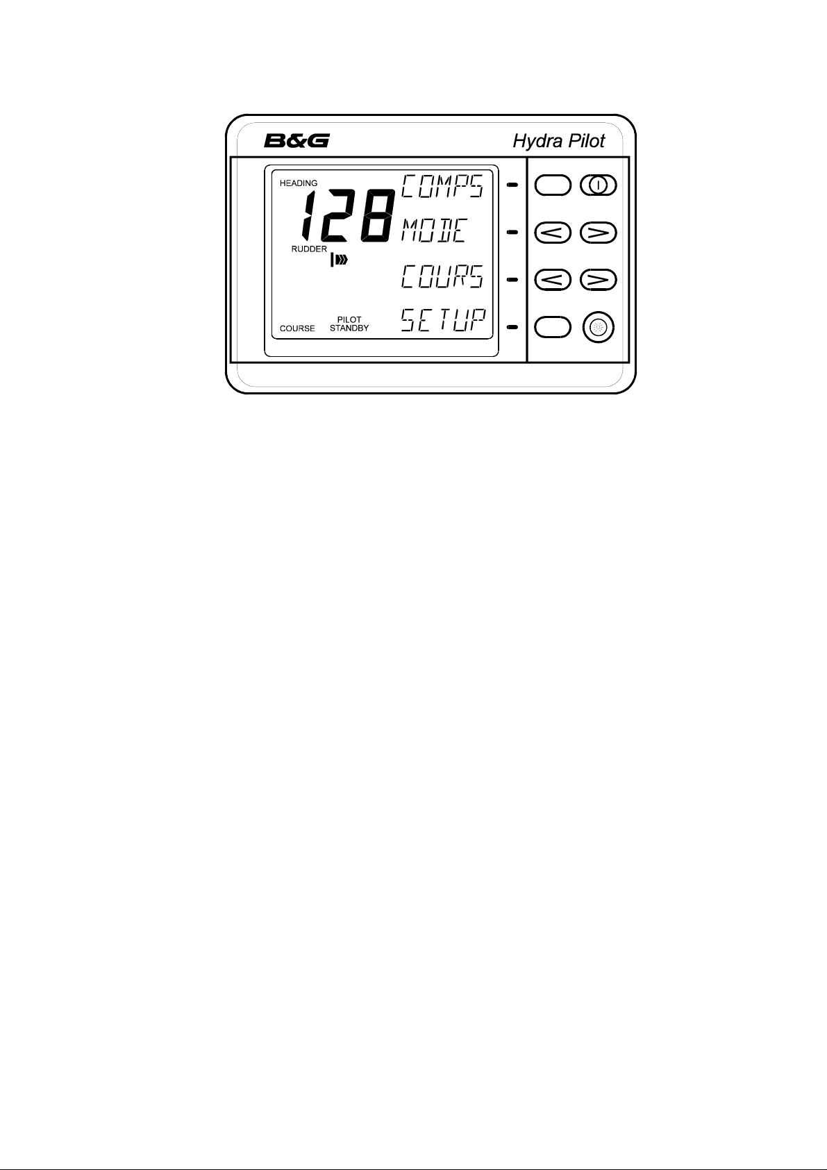
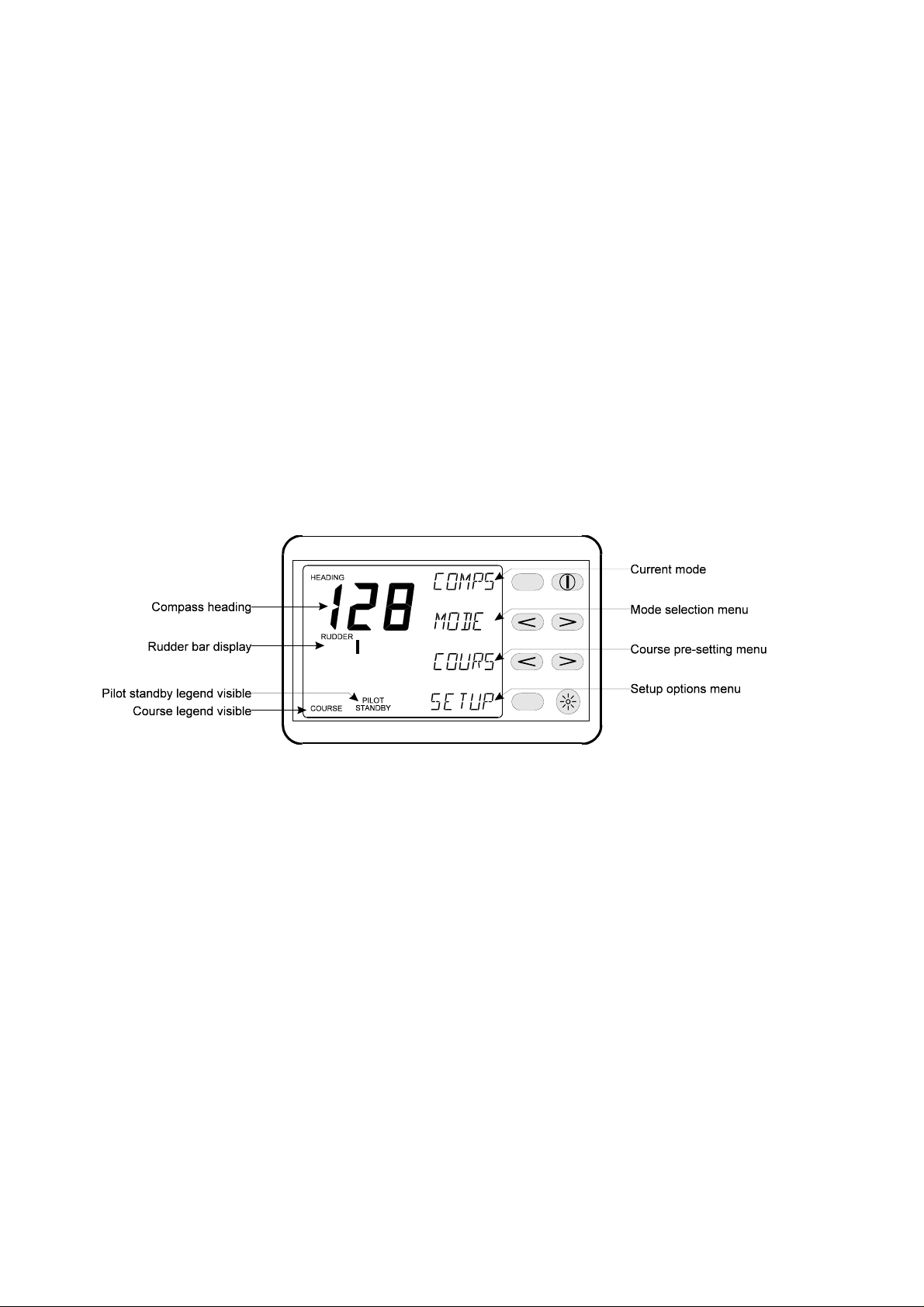
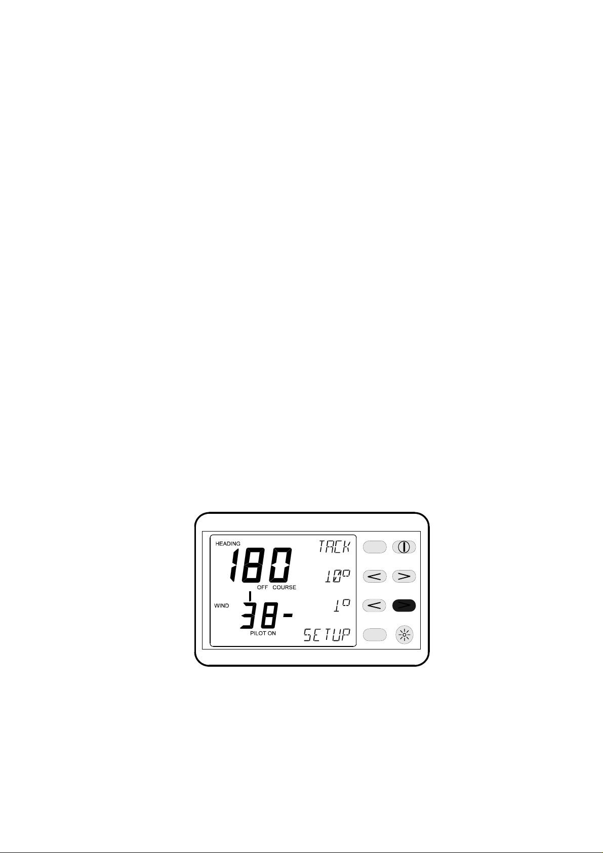
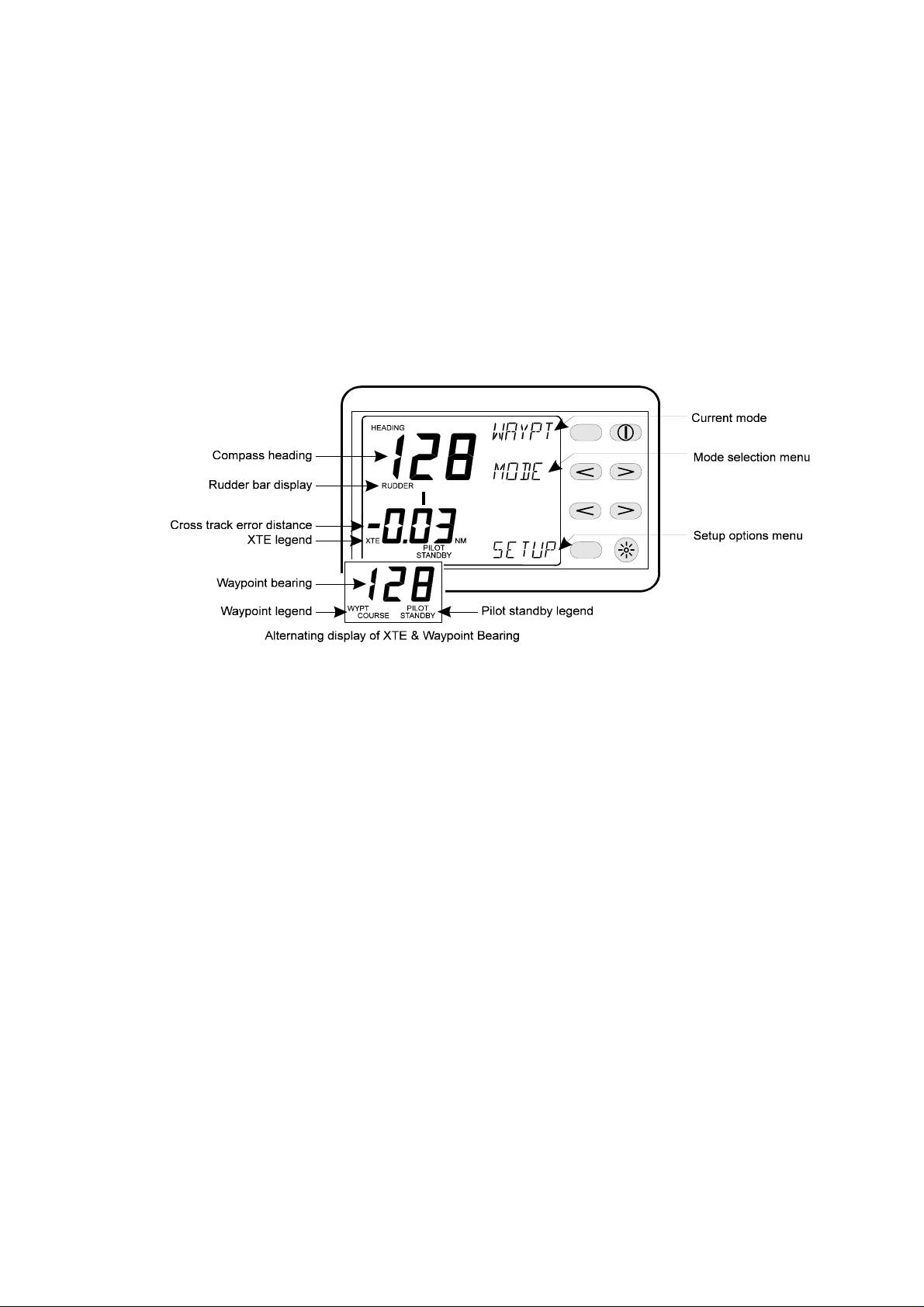
1.4 AUTOPILOT DISPLAY
Fig 1.1 - Autopilot Display
h2000 Autopilot User Manual
Part 1 - Introduction
The backlit Liquid Crystal Display (LCD) shows the following
information:
(a) Large Digits (top centre) - The current heading as
provided by the Autopilot Compass or Instrumentation
System.
(b) Rudder Legend (centre) - The mode selected for the
analogue bar immediately below. This can be set to
RUDDER or OFF COURSE.
(c) Rudder Bar Display (centre) - Analogue indication of
Rudder Angle in increments of 5q up to r35q. This can be
set to show either OFF COURSE or RUDDER ANGLE.
(d) Autopilot Legend - (bottom centre) - Indicates the
Autopilot Operational Status. This can be set to either
STANDBY or ON.
(e) Key Legends and Keypad (right top to bottom) - The
legends change according to the operating mode
selected, assigning different functions to each key as
required. Pressing the key(s) adjacent to each legend will
cause an action, e.g. Change of Course, or provide a list
of options and selections. These lists are referred to as
Menus and are fully described in Part 2 - Operating
Information.
1-5
HB-0842-04
Page 10
h2000 Autopilot User Manual
Part 1 - Introduction
(f) Red Off Key (top right of keypad) - This key
disengages the Autopilot and returns the boat to Manual
Steering. It has no other function.
(g) Lights Key (bottom right of keypad) - This key turns
the LCD back lighting ON and OFF, and allows three
levels of illumination to be selected for all displays
(including Instrument System FFDs) under system control.
It has no other function.
Note
The Autopilot can be disengaged at any time from any mode or
menu by pressing the Red Off Key.
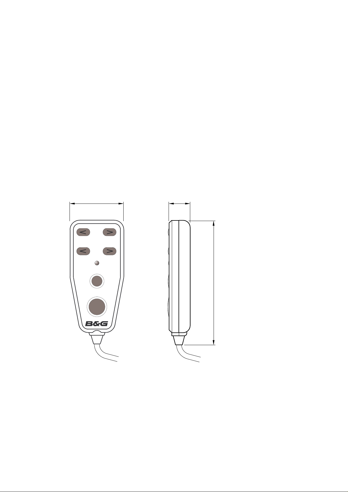
1.5 HAND-HELD CONTROLLER
56.5 24.0
10
1
auto/resume
off
128.0
Fig 1.2 - Hand-held Controller
The Hand-held Controller provides remote control of the h2000
Autopilot. The six keys used for dedicated functions are as follows:
(a) 10 degree course change (Port/Starboard).
(b) 1 degree course change (Port/Starboard).
HB-0842-04
1-6
Page 11
(c) Auto/Resume - Autopilot engage and return to course.
(d) Off - Autopilot disengage.
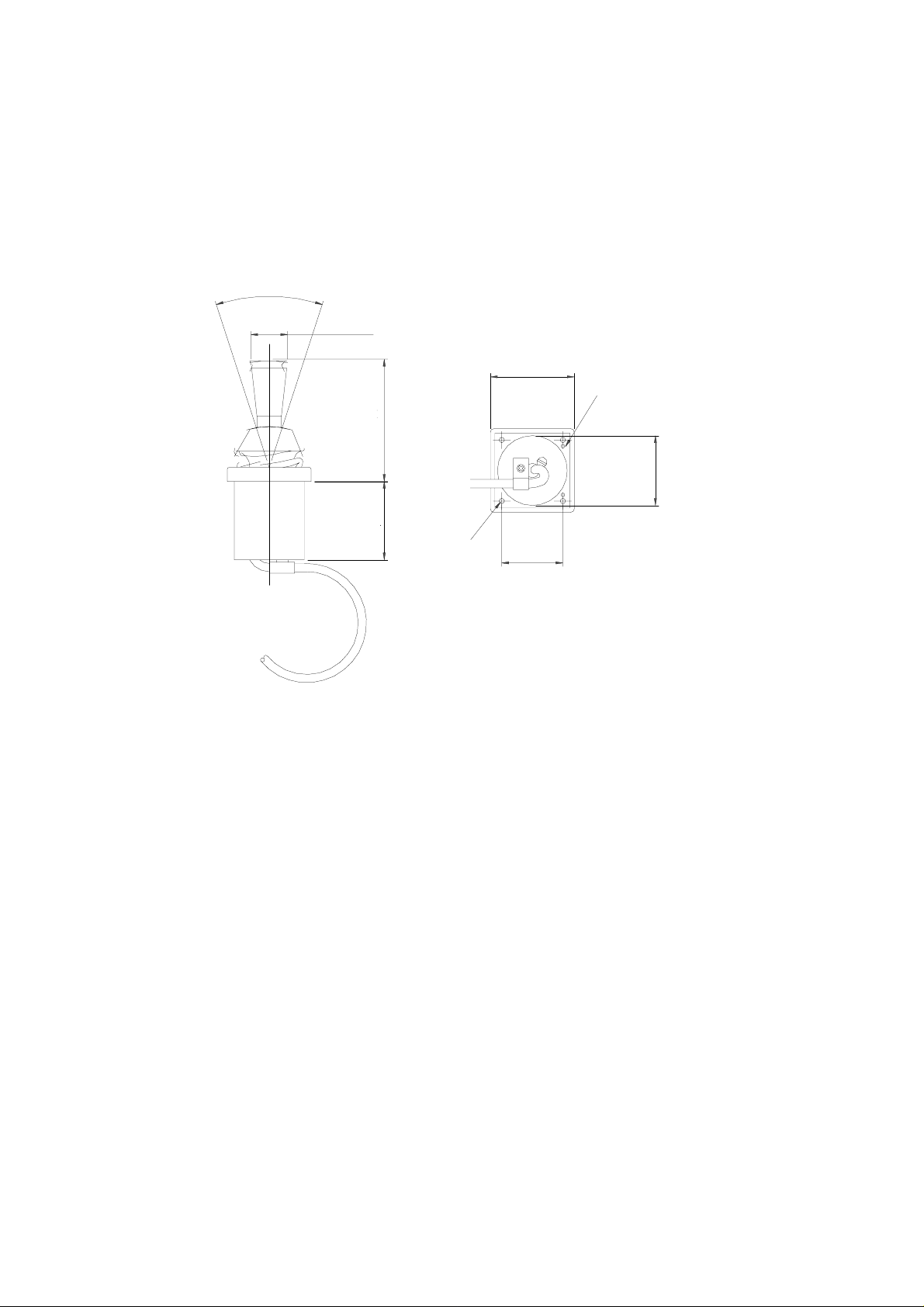
1.6 JOYSTICK
o
36.0
dia 21.0 mm
h2000 Autopilot User Manual
Part 1 - Introduction
View from underside
48.0 mm
Forward indicator marks
70. 0 mm
dia 40.0 mm
45.0 mm
4 holes
dia 3.0 mm
35.0 mm
Fig 1.3 - Joystick
The Joystick allows direct control of the rudder via the autopilot
control electronics. The unit is deck-mountable, allowing it to be
used inside or outside the steering positions. A 10m/30ft 6-core
screened cable connects the unit directly into the ACP unit’s
terminals. Joystick steering is engaged and disengaged with the
separate red button. The lever can only be moved to port and
starboard.
There are two modes of joystick operation available to the
Helmsman, these are as follows:
(a) Normal Steering (Norm) - The rudder moves in the
direction of the Joystick. When the Joystick is returned to
the central position the rudder movement stops. The
greater the movement of the Joystick the faster the
response of the rudder.
HB-0842-04
1-7
Page 12
h2000 Autopilot User Manual
Part 1 - Introduction
(b) Proportional Steering (Prop) - The position of the
rudder follows the position of the Joystick. When the
Joystick returns to the central position the rudder returns
to its initial position.
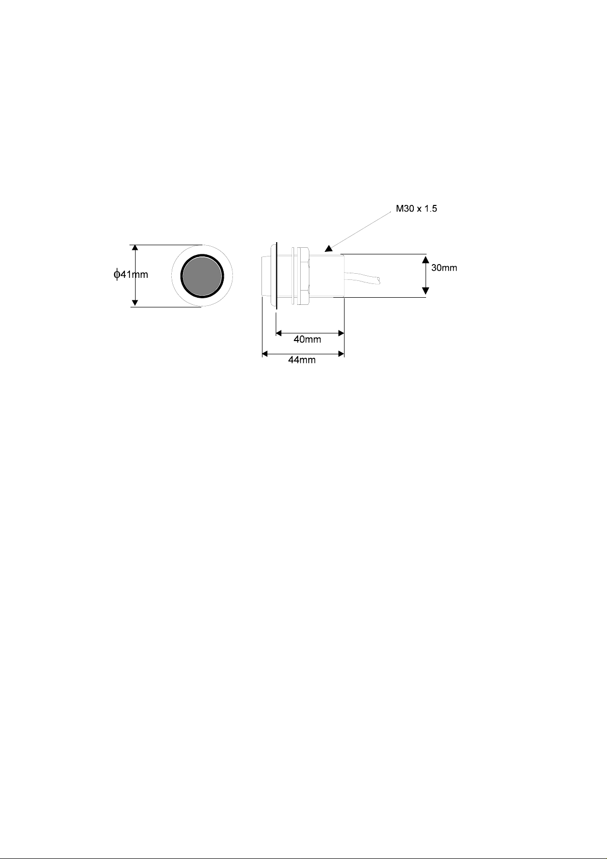
1.7 MAN OVERBOARD BUTTON
Fig 1.4 - Man Overboard Button
The Man Overboard Button (MOB) is an optional extra that
activates the Autopilot Man Overboard Alarm Procedure to assist
in the recovery of the person, or persons, that may have been lost
overboard. It may be used when the Autopilot is engaged or
disengaged.
For this facility to operate, a speed sensor input must be available.
It will not work with a user entered fixed speed or Speed Over
Ground from a Position Fixer.
Sailboats, because of the need to tack or gybe, must use Manual
recovery. The bearing and distance displays must be followed and
the boat steered back, either manually or under Autopilot Control,
to the person(s) in the water.
Powerboats can use the Autopilot for Automatic Recovery. When
the MOB is operated the Autopilot will control the steering to
execute a ‘Williamson Turn’ and return the boat on a reciprocal
course.
HB-0842-04
1-8
Page 13

h2000 Autopilot User Manual
Part 2 - Operating Information
PART 2 - OPERATING INFORMATION
CONTENTS
Para Page
2.1 SWITCHING ON 2-3
2.2 MODE SELECTION 2-4
2.2.1 Introduction 2-4
2.2.2 Mode Selection 2-4
2.3 STEER TO COMPASS 2-4
2.3.1 Introduction 2-4
2.3.2 Selecting Compass Mode 2-5
2.3.3 Engaging the Autopilot 2-5
2.3.4 Dis-engaging the Autopilot 2-5
2.3.5 Changing the Autopilot Course 2-6
2.3.6 Pre-setting the Autopilot Course 2-7
2.3.7 Pre-setting the Next Leg 2-7
2.4 STEER TO WIND INTRODUCTION 2-8
2.4.1 Hydra 2000 and Hydra Autopilot 2-8
2.4.2 Hercules and Hercules Autopilot 2-8
2.4.3 Selecting Wind Mode 2-9
2.4.4 Engaging the Autopilot 2-9
2.4.5 Dis-engaging the Autopilot 2-10
2.4.6 Steer to Wind Adjustments 2-10
2.4.7 Pre-setting the Target AWA 2-11
2.4.8 Auto Tack 2-12
2.4.9 Auto Gybe 2-13
2.4.10 Gybe Zone 2-13
2.4.11 Using the Gybe Key 2-14
2.5 STEER TO WAYPOINT 2-13
2.5.1 Steer to Waypoint Introduction 2-14
2.5.2 Selecting the Waypoint Mode 2-15
2.5.3 Engaging the Autopilot 2-15
2.5.4 Dis-engaging the Autopilot 2-16
2.5.5 Changing the Autopilot Course 2-16
2.5.6 Returning to Original Course 2-17
2.5.7 Waypoint Arrival Next Leg 2-17
2-1
HB-0842-04
Page 14

h2000 Autopilot User Manual
Part 2 - Operating Information
CONTENTS (Contd.)
Para Page
2.6 POWER STEER 2-18
2.6.1 Introduction 2-18
2.6.2 Selecting Power Steer Mode 2-18
2.6.3 Engaging the Autopilot 2-19
2.6.4 Dis-engaging the Autopilot 2-19
2.6.5 Fine Rudder Adjustments 2-19
2.6.6 Coarse Rudder Changes 2-20
2.6.7 Mid Key 2-20
2.7 JOYSTICK STEERING 2-20
2.7.1 Introduction to Joystick Steering 2-20
2.7.2 Engaging the Autopilot 2-21
2.7.3 Dis-engaging the Autopilot 2-22
2.7.4 Normal Steering 2-22
2.7.5 Proportional Steering 2-22
2.8 SET-UP OPTIONS 2-23
2.8.1 Manual Response Set-Up (RESP) 2-24
2.8.2 Mode Set-Up (MODE) 2-25
2.8.3 Automatic Response Set-Up (ARESP) 2-26
2.8.4 Recovery Mode Sensitivity (RECOV) 2-28
2.8.5 Speed Set-Up (SPEED) 2-29
2.8.6 Off Course Set-Up (Off-C) 2-30
2.8.7 Compass Damping Set-Up (C DMP) 2-31
2.8.8 NMEA Source Set-Up (N SRC) 2-32
2.8.9 Course Alarm Set-Up (CRS A) 2-34
2.8.10 Watch Alarm Set-Up (WATCH) 2-35
2.8.11 Back Lighting Set-Up (LIGHT) 2-36
2.8.12 Joystick Set-Up (JYSTK) 2-37
2.9 AUTOPILOT INFORMATION ON FFD 2-38
2.9.1 Autopilot Course (PLT CRSE °M) 2-38
2.9.2 Rudder Angle (RUDDER °) 2-38
2.9.3 Off Course Error (OFF CRSE °) 2-38
2.9.4 Man Overboard Facility (MAN OVER) 2-38
2.9.5 Autopilot Faults and Errors (PLT ERR) 2-38
2.10 MAN OVERBOARD FACILITY 2-39
2.10.1 Man Overboard Procedure 2-39
2.10.2 Manual Recovery (All Boats) 2-40
2.10.3 Automatic Recovery (Power Only) 2-40
HB-0842-04
2-2
Page 15

h2000 Autopilot User Manual
Part 2 - Operating Information
PART 2 - OPERATING INFORMATION
2.1 SWITCHING ON
The h2000 Autopilot has two power supplies (instrument and
heavy duty) connected via circuit breakers and/or fuses. The
Autopilot Computer and Autopilot Displays are powered via the
Fastnet data cable and share the same source of supply as the
Hydra, Hercules or HS2000 Instrument System.
The hydraulic ram, rotary drive or hydraulic pump supplies are
routed via the Autopilot Computer. The heavy-duty supply is
dedicated to the rudder drive unit and is connected via a separate
heavy-duty fuse or circuit breaker.
To switch the Autopilot ON, proceed as follows:
(1) Switch ON the heavy-duty power supply for the
rudder drive unit.
(2) Switch ON the instrument supplies.
The Autopilot will only operate if both the heavy duty and
instrument supplies are switched ON.
Notes
1. If the Autopilot Display indicates Fault 103 when engaged for
the first time, check that the heavy-duty drive supply is switched
ON.
2. If the Autopilot Display indicates the Fault Message above,
switch ON the heavy-duty supply and clear the fault message.
3. If the Autopilot Display shows Fault 104 when engaged, this
indicates that there is no boat speed input from the sensor. For
example, this would occur if the Autopilot were switched on at the
dockside.
4. To clear the Fault Message, press the key next to the FAULT
legend on any Autopilot Display twice. Alternatively, press the
Enter Key on any FFD twice.
HB-0842-04
2-3
Page 16
h2000 Autopilot User Manual
Part 2 - Operating Information
2.2 MODE SELECTION
2.2.1 Introduction
The Autopilot software automatically determines which modes of
operation are available depending on whether the vessel is a
powerboat or a sailboat. The Autopilot also receives Waypoint or
Wind data via the Fastnet databus from either a compatible
position fixer or the Masthead Unit.
At initial switch ON the Autopilot will be in Standby and Steer to
Compass (COMPS) mode.
2.2.2 Mode Selection
The mode is changed by pressing the key next to the MODE
legend on the FFD.
Each mode of steering is described in the following sections.
2.3 STEER TO COMPASS
2.3.1 Introduction
Steer to Compass is available with all Autopilot configurations for
sailboats and powerboats and is the basic method of Autopilot
steering. The boat is steered on the desired compass heading and
the Autopilot is engaged with a single key press. The Autopilot will
steer using heading data either from a Halcyon 2000 Compass
connected to the Fastnet databus, a Gyro sensor connected
directly to the Autopilot processor, or from the B&G Halcyon Gyro
Processor.
HB-0842-04
2-4
Page 17
2.3.2 Selecting Compass Mode
Press the < Key next to the MODE legend until COMPS
appears on the top line.
2.3.3 Engaging the Autopilot
(1) From the Autopilot Display and with the boat steered
on the desired course, press the Key next to the COMPS
legend.
h2000 Autopilot User Manual
Part 2 - Operating Information
(2) From the Hand-held Controller steer the boat onto
the desired course, press the Auto/Resume Key to
engage the Autopilot.
2.3.4 Dis-engaging the Autopilot
Note
When the Autopilot is engaged, the Instrument System FFDs
Power-Off Key is disabled, preventing accidental switching OFF of
the Autopilot and Instrument System.
(1) At any Autopilot Display press the Red Off Key. The
Autopilot immediately disengages and returns the boat to
manual steering.
(2) From the Hand-held Controller press the Red Off
Key. The Autopilot immediately disengages and returns
the boat to manual steering.
HB-0842-04
2-5
Page 18
h2000 Autopilot User Manual
Part 2 - Operating Information
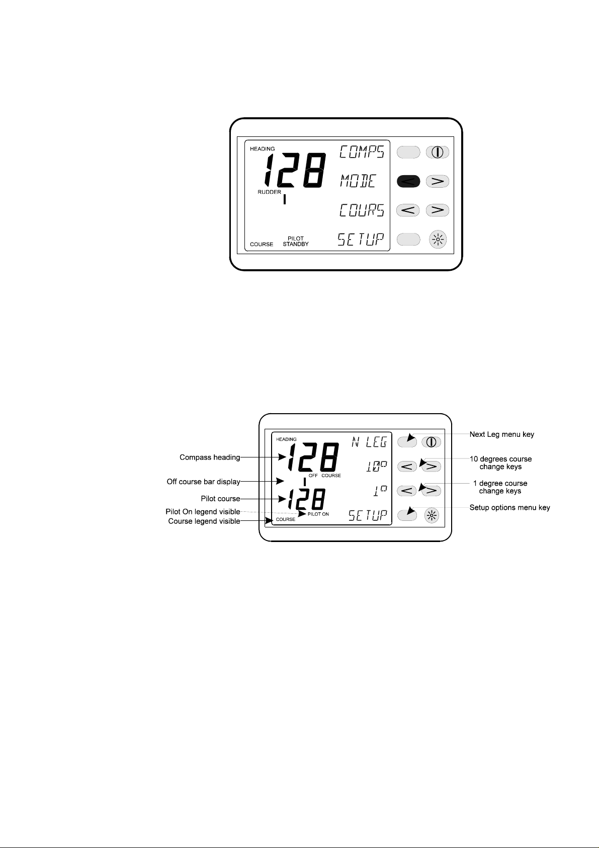
2.3.5 Changing the Autopilot Course
Note
The Autopilot can be immediately disengaged and the steering
returned to manual control by pressing the Red Off Key on any
Autopilot Display or Hand-held Controller.
(1) Fine Adjustments - Multiple key operations are
added together to give the required course change, e.g.
o
for a 5
course change press the 1o button 5 times.
(2) Coarse Adjustments - Multiple key operations are
added together to give the required course change, e.g.
o
for an 11
course change press the 10o+ 1o button.
HB-0842-04
2-6
Page 19

h2000 Autopilot User Manual
Part 2 - Operating Information
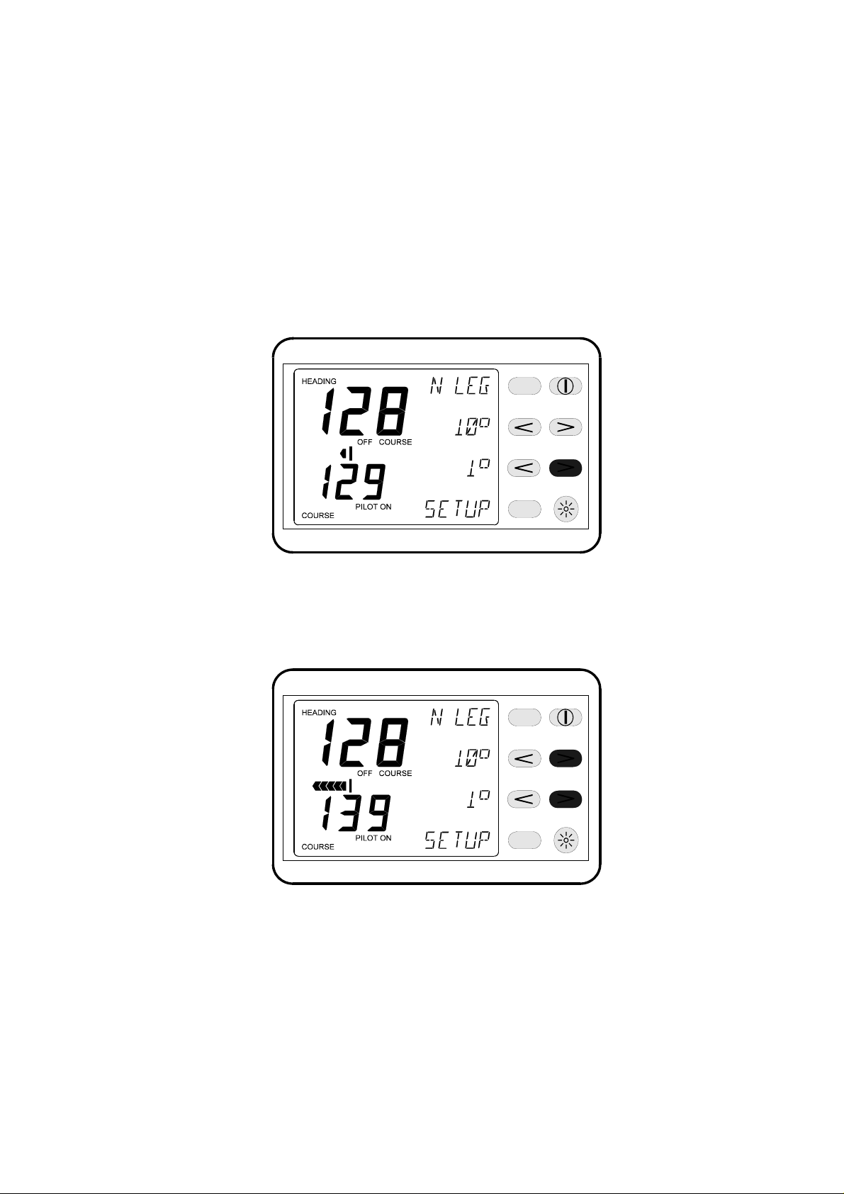
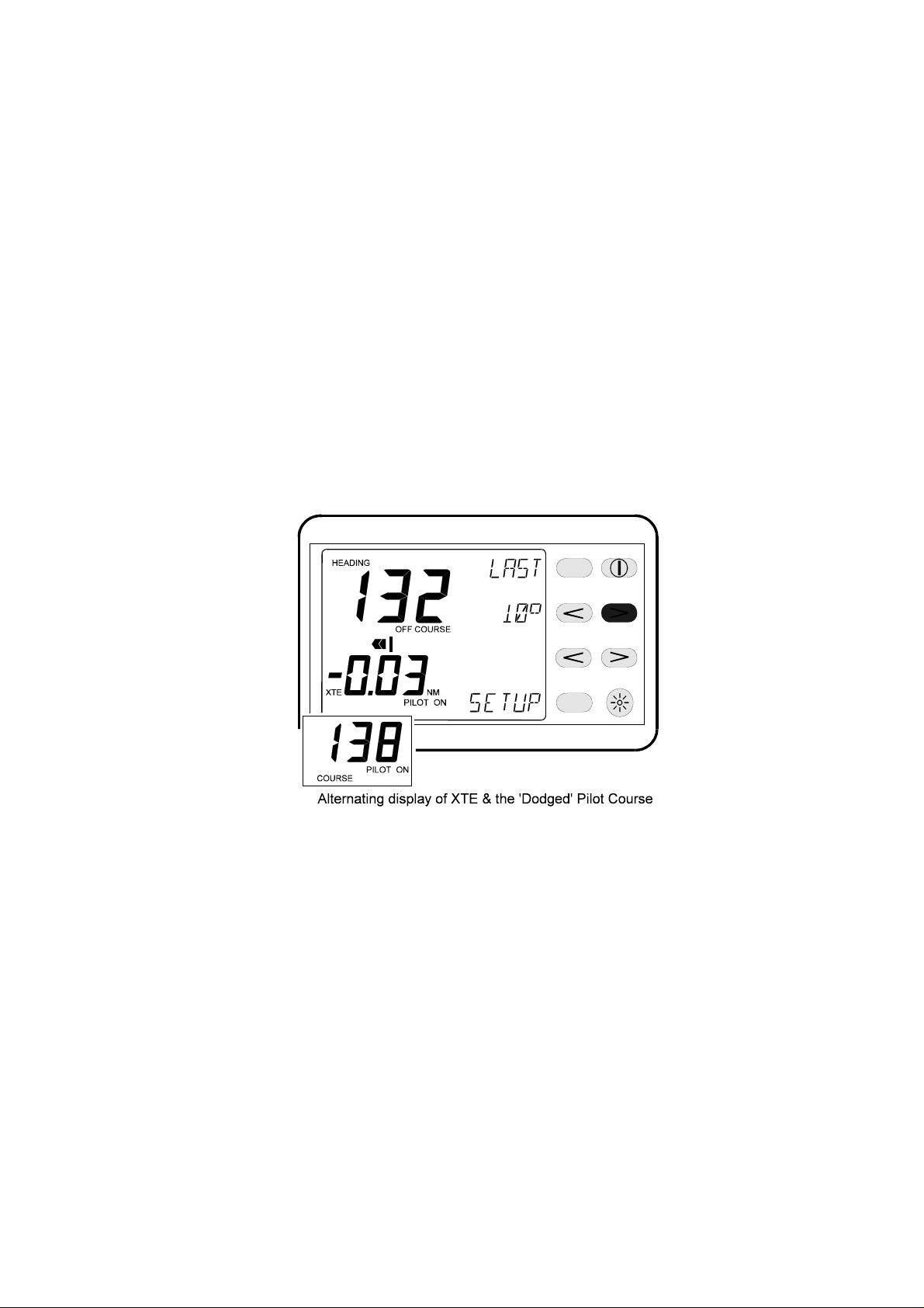
(3) Temporary Changes (Dodging) - At any Autopilot
o
display press the > Key next to the 10
the Autopilot course to starboard by 10
legend to change
o
. When the key is
pressed, the last course is stored in the Autopilot
Computer course memory. The Autopilot course digits
alternate between current and last course: Press the <
o
Key next to the 10
to port by 10
legend to change the Autopilot course
o
. The last course memory works as
described above.
At the Hand-held Controller press the Auto/Resume Key
to return to the original course.
USER TIP
o
The 10
and Last Keys can be used to "dodge" around
obstacles in the Autopilot’s course. Multiple key
operations are added together to give the required course
o
change, e.g. for a 20
course change press the 10oKey
twice.
Note
o
If the 1
o
Key, the course memory is cleared and the last
10
Key is pressed immediately after pressing the
course cannot be recalled. To return to the original
course use the Reciprocal Key.
2.3.6 Pre-Setting the Autopilot Course
(1) At any Autopilot Display, with the Autopilot System in
Standby, press the key next to the COURS legend to
display the Course Pre-setting Menu.
(2) Press the < Key (Decrease) and > Key (Increase)
next to the < < > > legend to alter the Autopilot course.
This is displayed on the LCD lower digits.
(3) Press the key next to the COMPS legend to engage
the Autopilot on the new pre-set course.
2.3.7 Pre-Setting the Next Leg
(1) At any Autopilot Display and with the Autopilot
engaged, press the key next to the N LEG legend to
display the Next Leg Pre-Setting Menu.
2-7
HB-0842-04
Page 20

h2000 Autopilot User Manual
Part 2 - Operating Information
(2) Press the < Key (Decrease) and > Key (Increase)
next to the < < > > legend to alter the Autopilot legend to
pre-set the Autopilot course, displayed on the lower
digits.
The keys next to the 10
required.
(3) When the course change is required, press the key
next to the ENTER legend.
The Autopilot will then steer the boat on to the pre-set
next course.
The course change can be abandoned at any time by
pressing the key next to the QUIT legend.
o
legend allow course dodges if
USER TIP
The Next Leg facility can be used to pre-set the next
course change before arriving at a Waypoint, point of
interest or navigational mark. It allows you to plan ahead.
2.4 STEER TO WIND INTRODUCTION
This mode of steering is only available to sailing boats that have a
Hydra or Hercules System fitted with a Masthead Unit.
2.4.1 Hydra Autopilot
When WIND is selected with a Hydra Autopilot System, the
Autopilot will steer a course that maintains a pre-defined Wind
Angle. If the Apparent Wind Angle (AWA) shifts, the Autopilot will
alter course so that the actual wind angle remains the same.
2.4.2 Hercules Autopilot
The Hercules Autopilot System has the additional feature of Steer
to Optimum Wind Angle. Data from the Hercules System's polar
tables, stored in the Performance Processor, allow the boat to sail
at the Optimum Wind Angle and is particularly useful for achieving
maximum VMG (Velocity Made Good) to windward.
HB-0842-04
2-8
Page 21
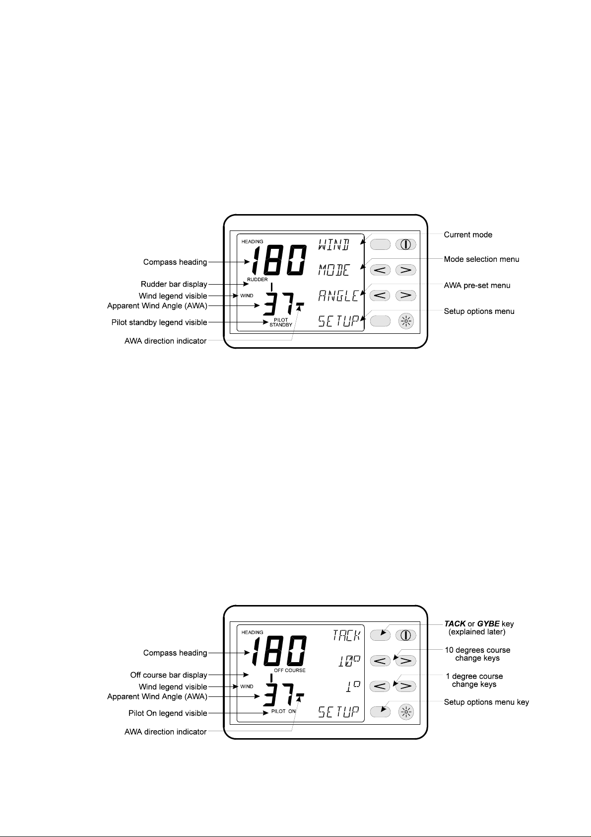
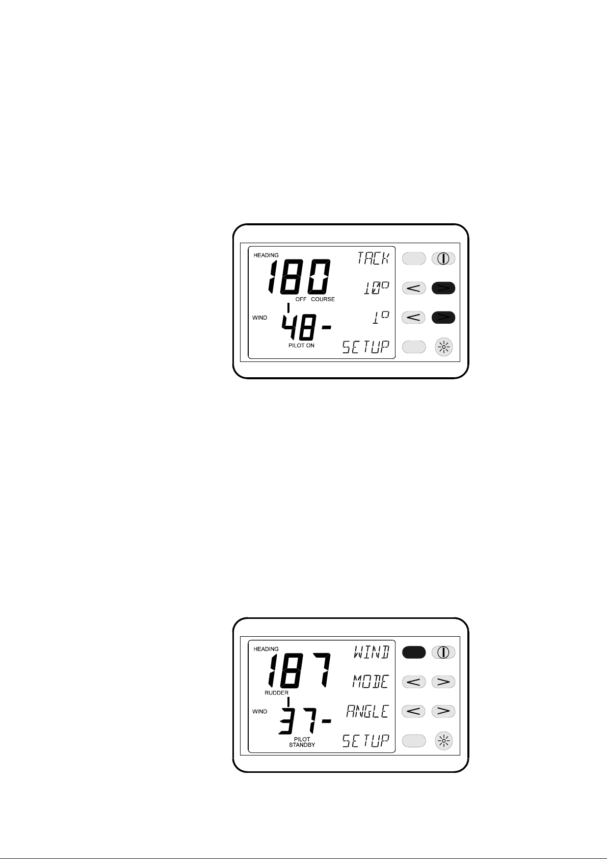
2.4.3 Selecting Wind Mode
(1) At the Autopilot Display press the key next to the
MODE legend until WIND appears on the top line.
The Apparent Wind Angle (AWA) displayed on the bottom
digits is the same as the displayed APP W/A on the
Instrument System. The position of the bar indicates the
direction of AWA:
h2000 Autopilot User Manual
Part 2 - Operating Information
Bar to the right of the digits, wind angle to starboard.
Bar to the left of the digits, wind angle to port.
2.4.4 Engaging the Autopilot
(1) At any Autopilot Display steer the boat until the
desired wind angle is displayed. Press the key next to the
WIND legend to engage the Autopilot.
(2) From any Hand-held Controller steer the boat until
the desired wind angle is displayed. Press the
Auto/Resume Key to engage the Autopilot with the
Hand-held Controller.
2-9
HB-0842-04
Page 22
h2000 Autopilot User Manual
Part 2 - Operating Information
2.4.5 Dis-engaging the Autopilot
(1) At any Autopilot Display press the Red Off Key. The
Autopilot disengages and returns to manual steering.
(2) At the Hand-held Controller press the Red Off Key.
The Autopilot disengages and returns to manual steering.
Notes
1. When the Autopilot System is steering to wind, course
changes are effected by changing the ‘target’ wind angle using the
o
10
and 1oKeys. The Autopilot calculates the course required to
maintain the new ‘target’ wind angle.
2. The Autopilot Wind mode does not have a course memory so
temporary course changes (dodges) are not possible. To return to
a previous course the reciprocal course changes must be entered.
2.4.6 Steer to Wind Adjustments
(a) Fine Adjustments - At any Autopilot Display press
o
the < Key next to the 1
‘target’ wind angle by 1
o
to starboard.
1
legend to change the Autopilot
o
to port, and the > Key to change
At the Hand-held Controller, press the 1
right to change the Autopilot ‘target’ wind angle to port or
starboard by 1
o
.
o
Keys left and
HB-0842-04
USER TIPS
Multiple key operations are added together to give the
o
required course change, e.g. for a 1
o
press the 1
button.
2-10
course change
Page 23
h2000 Autopilot User Manual
Part 2 - Operating Information
Multiple key operations are added together to give the
required wind angle change, e.g. for a 5
o
angle change press the 1
button 5 times.
o
‘target’ wind
(b) Coarse Adjustments - At any Autopilot Display
o
press the < Key next to the 10
the Autopilot ‘target’ wind angle by 11
o
Key to change 11
Controller press the 10
to starboard. At the Hand-held
o
Autopilot ‘target’ wind angle to port or starboard by 11
and 1olegends to change
o
to port and the >
and 1oKeys to change the
o
.
USER TIP
Multiple key operations are added together to give the
required course change, e.g. for an 11
o
press the 10
+ 1obutton.
o
course change
2.4.7 Pre-Setting the Wind Angle
When the boat is steered to a course and the Autopilot is then
engaged, the Wind Angle is approximate. When a specific Wind
Angle is required, this angle can be set up before engaging the
Autopilot.
(1) At the Autopilot Display and with Autopilot in Standby
press the key next to the ANGLE legend to display the
Wind Angle Pre-setting Menu.
2-11
HB-0842-04
Page 24
h2000 Autopilot User Manual
Part 2 - Operating Information
(2) Press the <> Keys next to the <<>> legend to alter
the wind angle displayed on the lower digits.
(3) Press the key next to the WIND legend to engage
the Autopilot on the User Defined Wind Angle. The boat
will now steer to the User pre-set wind angle.
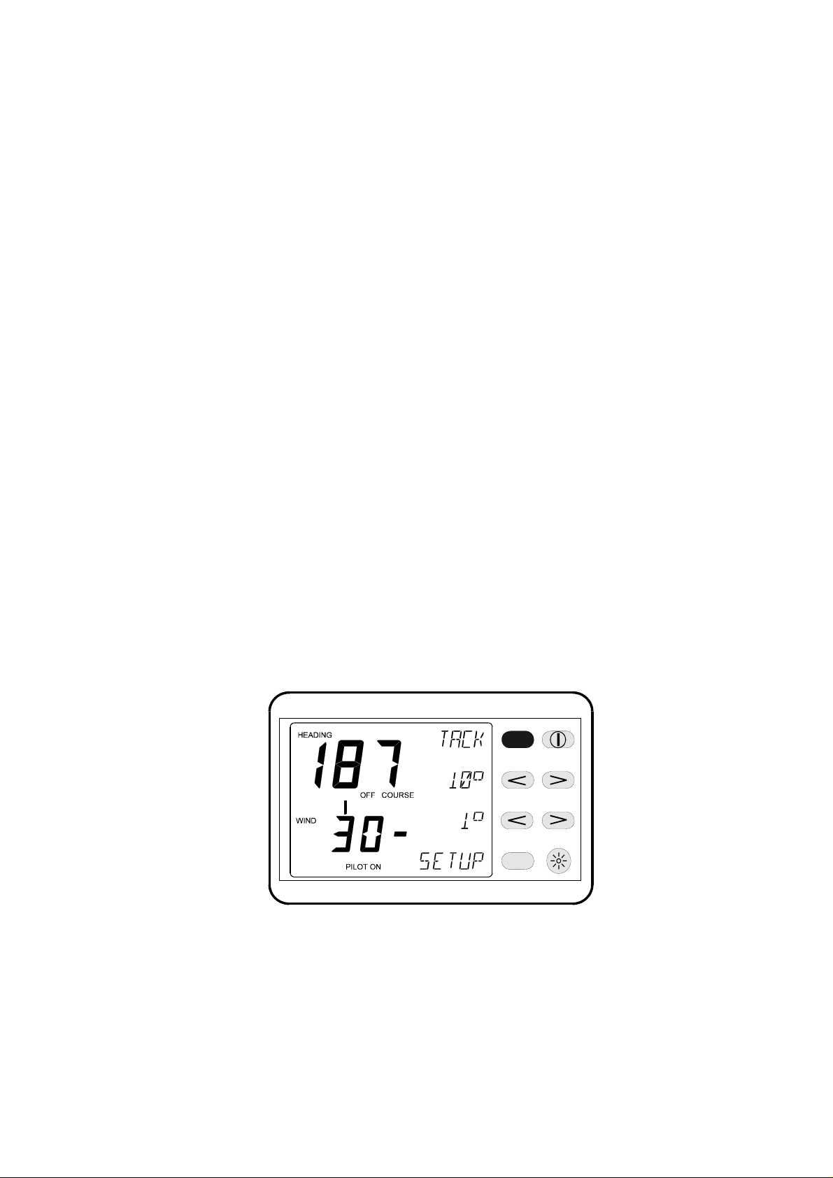
2.4.8 Auto Tack
When engaged in the Wind mode the Autopilot Computer
calculates the True Wind Angle (TWA), thus enabling the Autopilot
to indicate when it is possible to execute a Autopilot controlled
tack. When the Tack Key is pressed the boat will be steered on
the same User Defined Wind Angle but on the opposite tack.
The Autopilot software steers the boat through the wind, calculates
a new ‘target’ wind angle and adds 5
o
to force the boat to bear
away to ensure a fast pick up of speed. When the boat
approaches the modified wind angle, the Autopilot alters course to
sail to the original wind angle.
When the TWA is in the range of -90
o
to +90o, the boat is sailing in
the tack zone. When TACK is indicated on any Autopilot Display:
(1) Press the key next to the TACK legend to execute
an auto tack.
(2) At the Hand-held Controller press both the 10oKeys
simultaneously to execute an auto tack when the boat is
in the tack zone.
The boat will tack as described previously on the opposite tack.
HB-0842-04
2-12
Page 25
h2000 Autopilot User Manual
Part 2 - Operating Information
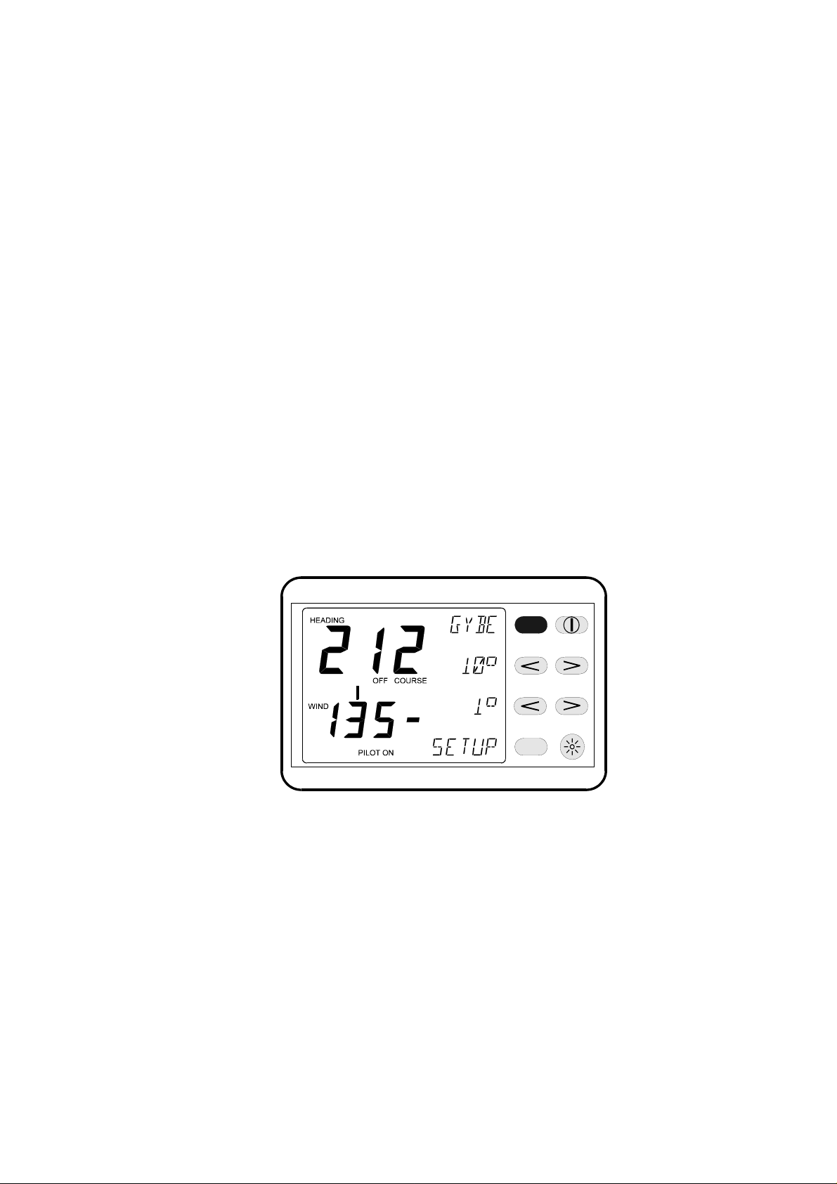
2.4.9 Auto Gybe
The Autopilot is also able to indicate when it is possible to execute
a Autopilot controlled gybe. When the Gybe Key is pressed the
boat will be steered on to exactly the same Target AWA, but on the
opposite tack.
The Autopilot software controls the steering so that the wind slowly
passes astern of the boat. This ensures the boom and sails are
safely transferred to the opposite tack.
2.4.10 Gybe Zone
o
When the TWA is in the range -120
to +120othe boat is sailing in
the gybe zone.
2.4.11 Using the Gybe Key
At any Autopilot Display, when in the gybe zone, the Autopilot
Display will show GYBE. Press the key next to the GYBE legend
to execute an auto gybe sequence.
2.5 STEER TO WAYPOINT
Notes
Before using Steer to Waypoint, check the following points:
(1) The position fixer has a compatible NMEA 0183
interface set-up in accordance with the manufacturer’s
instructions.
HB-0842-04
2-13
Page 26

h2000 Autopilot User Manual
Part 2 - Operating Information
(2) The appropriate NMEA sentences are selected and
set to be transmitted. The minimum data requirement is
XTE (cross track error); however, XTE and Bearing to
Waypoint give the best steering performance. For
Autopilot operation select any of the following: RMB (best
option), XTE, APA, or APB together with BWR or BWC.
(3) The position fixer is switched ON and has the correct
current position.
(4) The signal and noise levels are within the
manufacturer's recommended limits.
(5) The Waypoints have been entered correctly, and the
Waypoint arrival alarm is switched ON.
(6) If using Waypoints in a route or sail plan (cruise
plan), the Waypoints have been entered correctly and in
the correct order, the direction of the route has been
selected and the route is enabled.
2.5.1 Steer to Waypoint Introduction
This mode of steering is available to both sail and powerboats. It is
also available for Autopilot Systems that are using either a Hydra
or Hercules Instrument System, interfaced with a compatible
position-fixing device using NMEA 0183 protocols.
The position fixer can be a GPS (Global Positioning System) or
Loran-C receiver; which in turn could be interfaced with a chart
plotter.
When engaged in WAYPT mode the Autopilot will steer a course
using Waypoint data from the position fixer or plotter programmed
with the Waypoint positions.
It is important to remember that when the Autopilot is steering to a
Waypoint using NMEA data, any erratic data or positional errors
generated by the position fixer will be transferred to the Autopilot
via the NMEA interface and the Instrument System. Position fixer
errors can be due to many causes including: poor reception, bad
satellite constellation, radio beacon chain transitions, local
geography (e.g. in a marina) and high power transmitters.
HB-0842-04
2-14
Page 27
h2000 Autopilot User Manual
Part 2 - Operating Information
USER TIP
Position fixer errors can cause steering inaccuracy. Always
maintain a log and position plot on an up-to-date chart. Also,
remember to check that the Autopilot course (Waypoint to
Waypoint) will steer the boat clear of any obstacles, taking into
account the effects of tide.
2.5.2 Selecting the Waypoint Mode
At the Autopilot Display, press the key next to the MODE legend
until WAYPT appears on the top line.
2.5.3 Engaging the Autopilot
Note
Before pressing the Waypoint Key steer the boat manually until
the XTE distance is less than 0.03 NM and the heading is close to
the Waypoint Bearing (Waypt Course) as shown on the Autopilot
Display.
(1) At any Autopilot Display, press the key next to the
WAYPT legend to engage the Autopilot.
(2) Press the Auto/Resume Key to engage the Autopilot
from the Hand-held Controller.
Note
If XTE is more than 0.03 NM when the Autopilot is engaged in
o
Steer to Waypoint mode, the course will be altered by up to 30
to
bring the boat back onto track.
2-15
HB-0842-04
Page 28
h2000 Autopilot User Manual
Part 2 - Operating Information
2.5.4 Dis-engaging the Autopilot
(1) At the Autopilot Display press the Red Off Key. The
Autopilot immediately disengages and returns to manual
steering.
(2) At the Hand-held Controller press the Red Off Key.
The Autopilot immediately disengages and returns to
manual steering.
2.5.5 Changing the Autopilot Course
(1) At the Autopilot Display press the > Key next to the
10° legend to change the Autopilot course to starboard by
10°. The Autopilot previous course is stored in the course
memory and the LAST legend is displayed.
(2) Press the < Key next to the 10° legend to change the
Autopilot course to port. The Autopilot previous course is
stored in the course memory and the LAST legend is
displayed.
(3) At the Hand-held Controller, press the 10° Keys to
change the Autopilot course to port or starboard 10°.
Note
The 1° Keys do not function in the Waypoint mode.
USER TIP
Multiple key operations are added together to give the required
o
course change, e.g. for a 20
course change press the 10o Keys
twice.
HB-0842-04
2-16
Page 29
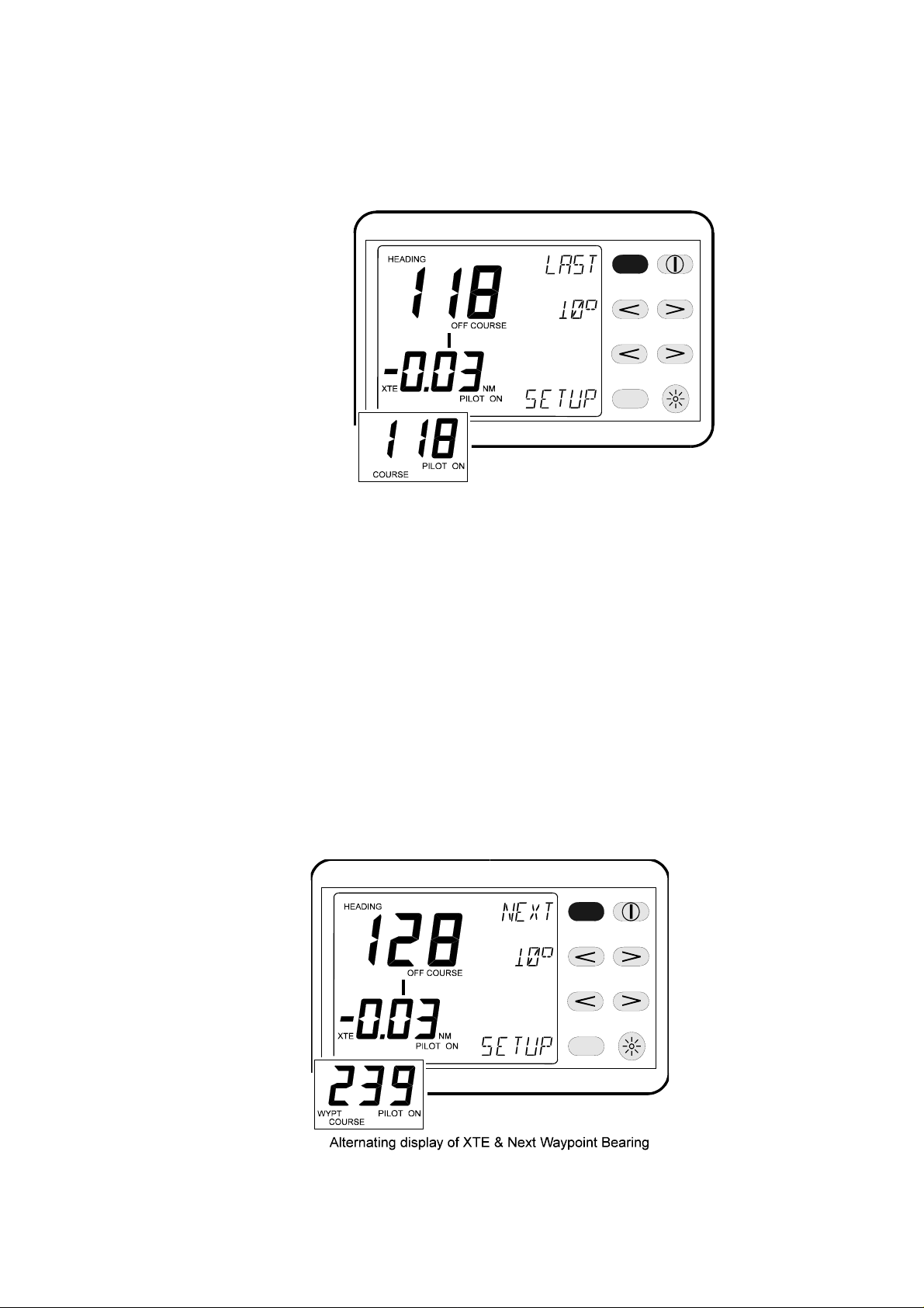
2.5.6 Returning to Original Course
(1) At the Autopilot Display, press the key next to the
LAST legend to resume the last course.
h2000 Autopilot User Manual
Part 2 - Operating Information
(2) At the Hand-held Controller press the Auto/Resume
Key to return to the original course.
2.5.7 Waypoint Arrival Next Leg
Many position fixers automatically switch to the next leg of a sail
plan when a programmed Waypoint is reached. The Autopilot will
not steer the boat to the next leg but displays a prompt to the
helmsman when the Waypoint is reached. The display shows
NEXT legend next to the top key.
At any Autopilot display, press the key next to the NEXT legend to
instruct the Autopilot to steer on the next leg of the sail plan.
2-17
HB-0842-04
Page 30
h2000 Autopilot User Manual
Part 2 - Operating Information
USER TIP
Allow a time margin for the next Waypoint bearing to stabilise
before pressing the next key.
Note
The Bearing to Waypoint must be supplied via the NMEA interface
for this function to operate; i.e. use one of the following NMEA
sentences: APB, BWC, BWR, and RMB.
2.6 POWER STEER
2.6.1 Introduction
Power steer is available with all Autopilot configurations for
sailboats and powerboats, and allows the helmsman to directly
control the boat’s rudder by either the Autopilot Display Unit keys
or the Hand-held Controller. When in Power Steer mode, the
Autopilot control software is by-passed and the key operations
directly control the rudder drive unit.
USER TIP
Power steer can be used in an emergency if the normal manual
steering became defective.
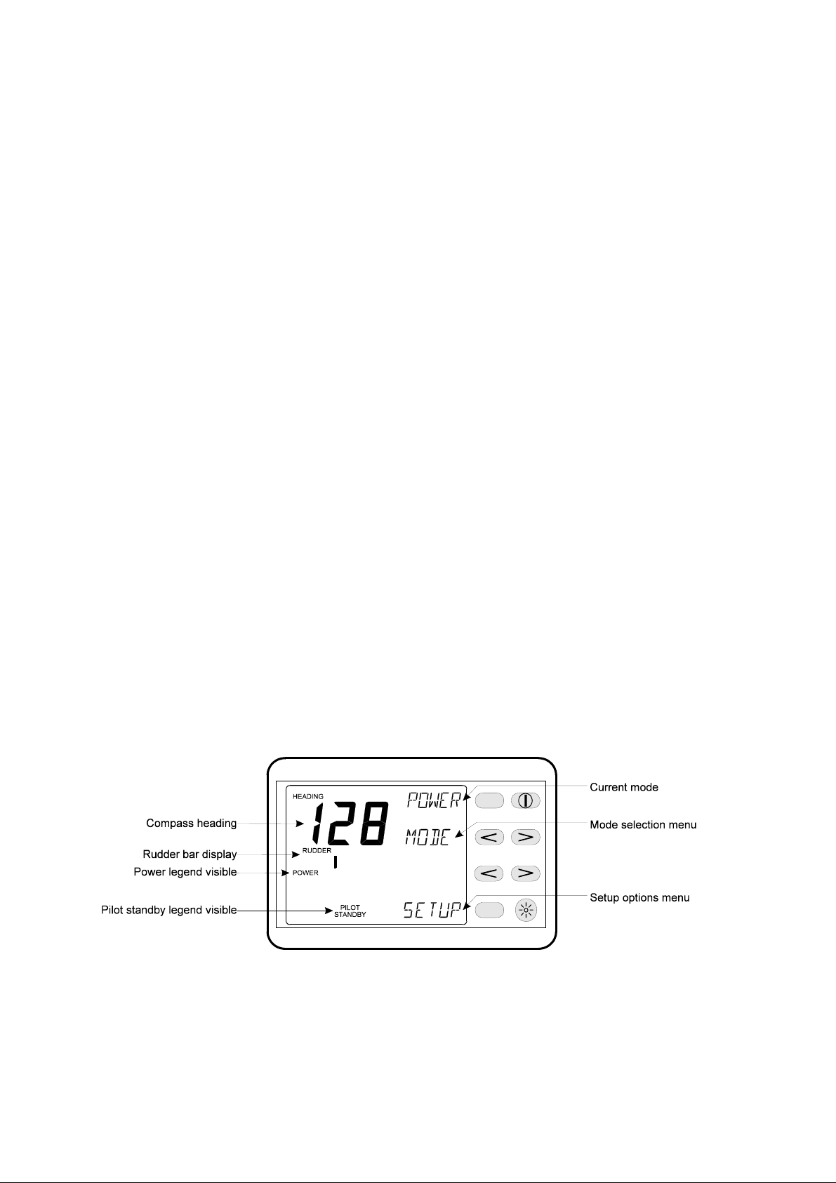
2.6.2 Selecting Power Steer Mode
At any Autopilot Display, press the key next to the MODE legend
until POWER appears on the top line.
HB-0842-04
2-18
Page 31

h2000 Autopilot User Manual
Part 2 - Operating Information
2.6.3 Engaging the Autopilot
Note
The rudder should be in the amidships position (or the position at
which the boat steers a straight course) before the Power Key is
pressed.
(1) At any Autopilot Display, press the key next to the
POWER legend to engage the Autopilot.
(2) At the Hand-held Controller press the Auto/Resume
Key to engage the Autopilot with the Hand-held
Controller.
2.6.4 Dis-engaging the Autopilot
(1) At the Autopilot Display press the Red Off Key. The
Autopilot immediately disengages and returns to manual
steering.
(2) At the Hand-held Controller press the Red Off Key.
The Autopilot immediately disengages and returns to
manual steering.
2.6.5 Fine Rudder Adjustments
(1) At the Autopilot Display press the > Key next to the
legend < > to move the rudder to starboard in steps of
o
0.6
.
(2) Press the < Key next to the legend < > to move the
rudder to port in steps of 0.6
(3) At the Hand-held Controller press the 1
move the rudder to port or starboard in steps of 0.6
o
.
o
Keys to
o
2-19
HB-0842-04
Page 32

h2000 Autopilot User Manual
Part 2 - Operating Information
USER TIP
Multiple operations of the keys are added together to give
the required rudder change.
2.6.6 Coarse Rudder Changes
(1) At the Autopilot Display press the < > Keys next to
the << >> legend to move the rudder to port or starboard
o
in steps of 3
.
(2) At the Hand-held Controller press the 10
move the rudder to port or starboard by 3
USER TIP
Multiple operations of the keys are added together to give
the required change
o
o
.
Keys to
2.6.7 Mid Key
Note
When the MID Key is pressed, the rudder will return to the position
set before POWER steer was engaged. If the rudder was set at the
amidships position then the MID Key will return the rudder to that
position.
(1) At any Autopilot Display press the key next to the
MID legend to return the rudder to the amidships position.
(2) At the Hand-held Controller press the Auto/Resume
Key to return the rudder to the amidships position.
2.7 JOYSTICK STEERING
2.7.1 Introduction to Joystick Steering
The joystick allows direct control of the rudder via the Autopilot
Computer for quick and responsive steering. Joystick steering is
engaged and disengaged with the separate Red Joystick Button.
The lever can only be moved to port or starboard. Refer to
Paragraph 2.8.12 to enable joystick steering.
HB-0842-04
2-20
Page 33

h2000 Autopilot User Manual
Part 2 - Operating Information
There are two joystick steering options available to the helmsman:
(a) Normal Steering (Norm) - The rudder moves in the
direction of the joystick. When the joystick returns to the
central position the rudder movement stops. The greater
the movement of the joystick, the faster the response of
the rudder.
(b) Proportional Steering (Prop) - The position of the
rudder follows the position of the joystick. When the
joystick returns to the central position the rudder returns
to its initial position.
2.7.2 Engaging the Autopilot
Turn the wheel until the rudder is in the amidships position, and
then press the separate Red Joystick Button.
Notes
1. Joystick mode can only be engaged by using the Joystick
Button.
2. When the Autopilot is engaged in Joystick mode the rudder
position (at the moment of engaging) will be the central (null)
position of the joystick. Ensure that the rudder is at the amidships
position before engaging the Autopilot.
USER TIP
To counteract any external influences on the steering, e.g. wind
and tide, steer the boat on to a straight and steady course before
engaging the Autopilot. This is only true so long as the same
course is maintained.
HB-0842-04
2-21
Page 34

h2000 Autopilot User Manual
Part 2 - Operating Information
2.7.3 Dis-engaging the Autopilot
(1) To dis-engage the Autopilot when in Joystick mode
press the Joystick Button and the boat will return to
manual steering.
(2) At the Autopilot Display press the Red Off Key. The
Autopilot disengages and returns to manual steering.
(3) At the Hand-held Controller press the Red Off Key.
The Autopilot disengages and returns to manual steering.
Note
The Autopilot can be immediately disengaged and the steering
returned to manual control by pressing the Red Off Key on any
Autopilot Display or Hand-held Controller.
2.7.4 Normal Steering
The rudder moves in the same direction as the joystick and the
display indicates the direction. When the spring-loaded joystick is
released, it returns to the central position and the rudder
movement stops and remains at this position. The speed of rudder
response is proportional to the joystick displacement.
2.7.5 Proportional Steering
When proportional steering is used, the rudder follows the rate and
direction of the joystick movement from hard to port to hard to
starboard. When the joystick is in the centre position, the rudder is
amidships. The Autopilot LCD rudder bar display indicates the
rudder position.
HB-0842-04
2-22
Page 35

h2000 Autopilot User Manual
Part 2 - Operating Information
2.8 SET-UP OPTIONS
The Hydra and Hercules Autopilots have eleven common set-up
options, however if a Halcyon Gyro Stabilised Compass and its
associated processor are installed into the Autopilot system,
additional set-up options become available. All set-up options are
used to change and select the operating modes, steering
characteristics and alarms of the Autopilot System, whether it is
fitted to a powerboat or a sailing boat.
The Set-up Menu is accessed by pressing the key next to the
SETUP legend on any Autopilot Display Unit, and is available
when the Autopilot is either engaged or disengaged in any steering
mode.
When the Set-up Menu is displayed, the set-up options can be
listed, changed and entered in to the Autopilot memory. The
diagram below shows a typical display when using the Set-up
Menu.
To exit the Set-up Menu following completion of the set-up
procedures described in the Paragraphs 2.8.1 to 2.8.12 press the
key next to the EXIT legend. The LCD will return to the previous
display before selection of the Set-up Menu.
2-23
HB-0842-04
Page 36

h2000 Autopilot User Manual
Part 2 - Operating Information
2.8.1 Manual Response Set-Up (RESP)
The RESP set-up controls the response of the steering. Different
selections are available dependent on whether the heading source
is from the Halcyon 2000 Compass or a B&G Halcyon Gyro
compass.
Response Settings with Halcyon 2000 Compass
(a) NORM - Normal course keeping and rudder
response (default).
(b) ECON - Economy: the rudder movement is limited,
this reduces the overall power consumption of the
Autopilot System, however there is a slight reduction in
course keeping.
(c) DWIND - Down-wind; the response is changed for
down-wind steering by applying the rudder more quickly.
This allows the Autopilot to hold a better course in
adverse conditions, such as sailing down-wind or with a
quartering sea. However there is an increase in the
power consumption.
Response Settings with B&G Halcyon Gyro
(a) NORM - Normal course keeping and rudder
response (default).
(b) ECON - Economy: the rudder movement is limited,
this reduces the overall power consumption of the
Autopilot System, however there is a slight reduction in
course keeping.
(c) PERF 1 to 4 – The PERF function allows for a manual
increase or decrease of steering response by using the
UP/DOWN arrow keys.
HB-0842-04
Of the four PERF settings, PERF 1 is the minimum
setting and PERF 4 is the maximum.
2-24
Page 37

To set-up RESP:
(1) Press the key shown until RESP is displayed.
(2) Press the key shown to scroll through the list of
RESP options.
h2000 Autopilot User Manual
Part 2 - Operating Information
NORM
ECON
PERF 1
PERF 2
PERF 3
PERF 4
(3) When the required response is displayed press the
key next to the ENTER legend. Continue with set-up or
press the key next to the EXIT legend to return to the
normal Autopilot display.
2.8.2 Mode Set-Up (MODE)
The MODE set-up allows the steering mode to be changed while
the Autopilot is engaged. Dependent upon the Autopilot and
Instrument System configuration fitted, there are four options
available:
(a) COMP - Steer to Compass.
(b) WIND - Steer to Wind.
(c) OPT W - Steer to Optimum Wind (Hercules
Autopilot).
(d) WAYPT - Steer to Waypoint.
2-25
HB-0842-04
Page 38

h2000 Autopilot User Manual
Part 2 - Operating Information
To set-up MODE:
(1) Press the key shown until desired MODE is
displayed.
(2) Press the key shown to scroll through the list of
MODE options.
(2) When the required mode is displayed press the key
next to the ENTER legend. Continue with set-up or
press the key next to the EXIT legend to return to the
normal Autopilot display.
2.8.3 Automatic Response Set-Up (ARESP)
This option is only available if a Halcyon Gyro Stabilised Compass
is fitted. The ARESP set-up enables the Autopilot to automatically
alter the response of the steering to be selected. There are four
options available:
(a) OFF – In this mode the Autopilot will remain in the
response mode selected in section 2.8.1.
(b) ECON – Economy: in this mode, the Autopilot will
need to sense large environmental changes before it will
increase its response rate.
HB-0842-04
2-26
Page 39

h2000 Autopilot User Manual
Part 2 - Operating Information
(c) NORM – Normal: in this mode, the Autopilot will
respond to moderate changes in environmental state
before altering its response rate.
(d) SPORT – in this mode, the Autopilot will be most
sensitive to changing conditions and will automatically
increase its response rate to counter environmental
changes.
The Automatic Response setting will not drop below the manual
response setting discussed in section 2.8.1. When the conditions
have improved, the Autopilot will automatically return to the
manual response setting.
To set-up ARESP:
(3) Press the key shown until ARESP is displayed.
ARESP
(2) Press the key shown to scroll through the list of
RESP options.
EXIT
ARESP
OFF
ECON
NORM
SPORT
(3) When the required response is displayed press the
key next to the ENTER legend. Continue with set-up or
press the key next to the EXIT legend to return to the
normal Autopilot display.
HB-0842-04
2-27
Page 40

h2000 Autopilot User Manual
Part 2 - Operating Information
2.8.4 Recovery Mode Sensitivity (RECOV)
This function is only available when a Halcyon Gyro Stabilised
Compass is connected to the system.
Recovery Mode allows the user to select the sensitivity that allows
the Autopilot to react to unexpected events, for example sudden
wave or wind shifts. This function allows the Autopilot to
instantaneously increase the steering response to its maximum
setting (PERF 4), and make a rapid recovery.
The Recovery Mode will automatically switch off after 15 seconds
or when the heading error has been corrected. The Autopilot will
then resume the previous response setting and continue normal
operation.
There are four options available dependent on the severity of the
prevailing conditions:
(a) Off - the Recovery Mode function is switched off.
(b) WIDE - in this setting, the Autopilot is least
sensitive to sudden course changes.
(c) MED - in this setting, the Autopilot is configured to
the medium value when correcting sudden course
changes.
(d) NARR - in this setting, the Autopilot is most
sensitive to sudden course changes.
HB-0842-04
2-28
Page 41

h2000 Autopilot User Manual
Part 2 - Operating Information
2.8.5 Speed Set-Up (SPEED)
The SPEED set-up allows the source used for speed data to be
selected. There are three options available:
(a) B SPD - Boat speed from a speed sensor (default).
(b) SOG - Speed Over Ground from NMEA device.
(c) F SPD - Fixed speed entered by the user.
To set-up SPEED:
(1) Press the key shown until SPEED is displayed.
(2) Press the key shown to scroll through the list of
SPEED options.
Note
SOG will only be displayed when the Autopilot is
receiving valid NMEA data from a position fixer. The
default set-up is B SPD.
2-29
HB-0842-04
Page 42

h2000 Autopilot User Manual
Part 2 - Operating Information
(3) When B SPD or SOG are selected, press the key
next to the ENTER legend. Continue with set-up or press
the key next to the EXIT legend to return to the normal
Autopilot display.
(4) When F SPD is selected press the key next to the
ENTER legend and proceed with steps (5) and (6) to set
the fixed speed value.
(5) Use the keys shown to adjust the value in
increments of 0.5 to the desired fixed speed within the
range 0.5 to 60.0.
Note
The default value for a sailboat is 8.0 knots and 25.0
knots for a powerboat.
(6) Press the key next to the ENTER legend to set the
fixed speed value. Continue with set-up or press the key
next to the EXIT legend to return to the normal Autopilot
display.
2.8.6 Off Course Set-Up (OFF C)
The OFF C set-up selects the Autopilot Display to show either off
course or rudder angle when the Autopilot is engaged in COMP,
WIND, OPT W or WAYPT modes of steering. There are two
options available:
(a) ON - The bar display shows OFF COURSE (default).
(b) OFF - The bar display shows RUDDER.
To set-up OFF C:
(1) Press the key shown until OFF C is displayed.
HB-0842-04
2-30
Page 43

h2000 Autopilot User Manual
Part 2 - Operating Information
(2) Press the key shown to select the display function of
the bar display when the Autopilot is engaged.
(3) When the required display function is displayed
press the key next to the ENTER legend. Continue with
set-up or press the key next to the EXIT legend to return
to the normal Autopilot display.
2.8.7 Compass Damping Set-Up (C DMP)
The C DMP set-up is the amount of damping (response to change)
applied to the displayed value of compass heading (top digits of
Autopilot Display Unit LCD) and can be set in the range 0 to 99
seconds. The default setting is four.
Note
This does not affect the response of the Autopilot.
To set-up C DMP:
(1) Press the key shown until C DMP is displayed.
2-31
HB-0842-04
Page 44

h2000 Autopilot User Manual
Part 2 - Operating Information
(2) Use the keys shown to adjust the value within the
range 0 to 99 seconds.
(3) When the required value is displayed press the key
next to the ENTER legend. Continue with set-up or press
the key next to the EXIT legend to return to the normal
Autopilot display.
2.8.8 NMEA Source Set-Up (N SRC)
The N SRC set-up selects the source of NMEA data when more
than one NMEA position fixer is connected to the Hydra or
Hercules Instrument System. The selections displayed depend
upon the NMEA data that is being received by the instrument
system. The options are listed below:
(a) AT 0 - Automatic selection (default).
(b) GP - GPS data.
(c) LC - Loran-C data.
HB-0842-04
(d) II - Integrated Instrument data.
2-32
Page 45

h2000 Autopilot User Manual
Part 2 - Operating Information
Note
When more than one of the same type of NMEA position fixer is
connected, i.e. two GPS receivers, then the number following the
device identifier, e.g. GP 96, determines which GPS is supplying
the NMEA data.
To set-up N SRC:
(1) Press the key shown until N SRC is displayed.
(2) Press the key shown to scroll through the list of
available N SRC options.
(3) When the required setting is displayed press the key
next to the ENTER legend. Continue with set-up or press
the key next to the EXIT legend to return to the normal
Autopilot display.
2-33
HB-0842-04
Page 46

h2000 Autopilot User Manual
Part 2 - Operating Information
2.8.9 Course Alarm Set-Up (CRS A)
The CRS A set-up enables the Course Alarm facility. The Autopilot
will sound an alarm (if an audible alarm is fitted to the instrument
system) and all the system displays flash a warning when the
Autopilot off course error is greater than the value set. The alarm
is temporarily disabled while the boat is turning. There are two
selections:
(a) OFF - The alarm is disabled (default).
(b) 1 to 180 - A number is set in degrees. The alarm is
enabled when the value is entered.
To set-up CRS A:
(1) Press the key shown until CRS A is displayed.
(2) Use the keys shown to adjust the value within the
range OFF to 180
o
.
HB-0842-04
(3) When the required value is displayed press the key
next to the ENTER legend. Continue with set-up or press
the key next to the EXIT legend to return to the normal
Autopilot display.
2-34
Page 47

h2000 Autopilot User Manual
Part 2 - Operating Information
2.8.10 Watch Alarm Set-Up (WATCH)
The WATCH set-up enables the watch alarm facility. The Autopilot
will sound an alarm (if an audible alarm is fitted to the Instrument
System) and cause all the system displays to flash a warning at a
pre-set time interval to keep the helmsman and crew alert. There
are two selections:
(a) OFF - The alarm is disabled (default).
(b) 1 to 360 - A number is set in minutes. The alarm is
enabled when the value is entered.
To set-up WATCH:
(1) Press the key shown until WATCH is displayed.
(2) Use the keys shown to adjust the value within the
range OFF to 360 minutes.
(3) When the required value is displayed press the key
next to the ENTER legend. Continue with set-up or press
the key next to the EXIT legend to return to the normal
Autopilot display.
2-35
HB-0842-04
Page 48

h2000 Autopilot User Manual
Part 2 - Operating Information
2.8.11 Back Lighting Set-Up (LIGHT)
The LIGHT set-up alters the LCD backlighting colour for all
Autopilot Displays and FFDs connected to the system. There are
two selections:
(a) RED (default).
(b) GREEN.
To set-up LIGHT:
(1) Press the key shown until LIGHT is displayed.
(2) Press the key shown to select either RED or
GREEN.
(3) When the required setting is displayed press the key
next to the ENTER legend. Continue with set-up or press
the key next to the EXIT legend to return to the normal
Autopilot display.
HB-0842-04
2-36
Page 49

h2000 Autopilot User Manual
Part 2 - Operating Information
2.8.12 Joystick Set-Up (JYSTK)
The JYSTK set-up selects the joystick steering, see the joystick
section of this manual for details about the different steering
modes. There are two selections:
(a) NORM - Normal steering mode (default).
(b) PROP - Proportional steering mode.
To set-up JYSTK:
(1) Press the key shown until JYSTK is displayed.
(2) Press the key shown to select either NORM or
PROP.
(3) When the required setting is displayed press the key
next to the ENTER legend. Continue with set-up or press
the key next to the EXIT legend to return to the normal
Autopilot display.
2-37
HB-0842-04
Page 50

h2000 Autopilot User Manual
Part 2 - Operating Information
2.9 AUTOPILOT INFORMATION ON FFD
The Hydra or Hercules Instrument System FFD (full function
display) can be configured to display a limited range of Autopilot
information. This information is accessed via the Autopilot Menu
that only appears when a Autopilot is connected. The following
information is available on any system FFD.
o
2.9.1 Autopilot Course (PLT CRSE
M)
The FFD can display the Autopilot course in degrees magnetic.
The displayed digits are the same as the lower digits of the
Autopilot Display Unit. When the Autopilot is engaged the
AUTOPILOT ON legend appears on the FFD. When the Autopilot
is disengaged, the FFD will show OFF where Autopilot information
is normally displayed.
2.9.2 Rudder Angle (RUDDER
o
)
The rudder angle can be displayed when the Autopilot is engaged
or disengaged; this is particularly useful for manoeuvring. The
angle is shown in degrees port or starboard of the amidships
position, indicated by two bars to the left or right of the digits.
o
2.9.3 Off Course Error (OFF CRSE
)
The digits display the difference between the compass heading
and the Autopilot course in degrees. A "dog-leg" symbol indicates
the direction to steer to correct the course error. When the
Autopilot is disengaged, the display will show OFF.
2.9.4 Man Overboard Facility (MAN OVER)
The Man Overboard Button (MOB) is an optional extra that when
fitted can be used to activate the MOB procedure. This can be
used as an aid in recovering personnel or equipment lost
overboard.
Under normal operating conditions, the display will show a NO
legend. When activated the FFD shows an alternating display of
Bearing and Distance to the MOB.
2.9.5 Autopilot Faults and Errors (PLT ERR)
The Autopilot is constantly self-checking for correct operation. If an
error occurs or a parameter is outside the normal operating
specification, then the FFD can display a number that relates to a
fault. See Part 6 - Diagnostic Data.
HB-0842-04
2-38
Page 51

h2000 Autopilot User Manual
Part 2 - Operating Information
2.10 MAN OVERBOARD FACILITY
The Man Overboard Button (MOB) is an optional extra that
activates the Autopilot's Man Overboard alarm procedure. The
MOB can be used whether the Autopilot is engaged or
disengaged.
The purpose of this feature is to aid in the recovery of crew or
passengers lost overboard. By sending the bearing and distance
to the Autopilot, the execution of a “Williamson Turn” can be
achieved automatically. The boat is returned to the position at
which the MOB was pressed.
2.10.1 Man Overboard Procedure
For this facility to operate there is a requirement to have a speed
sensor input. User entered fixed speed or Speed Over Ground
from a position fixer will not activate the MOB procedure.
Sailboats, because of the need to tack or gybe, must use Manual
Recovery. The boat is steered back to the MOB position, following
the bearing and distance displays, either manually or under
Autopilot control.
Powerboat owners, however, can use the Autopilot for Automatic
Recovery. The Autopilot will control the steering of the boat to
execute a "Williamson Turn" and return the boat along the
reciprocal course.
When the MOB is pressed, the Instrument System audible alarm
will sound (if fitted), the LCDs will show the MOB message and if
the back-lighting is ON, the colour will flash from red to green.
Pressing the Enter Key twice on any Full Function Display silences
the alarm.
The full procedures for Manual and Automatic Man Overboard
Recovery are described overleaf. These procedures should be
practised and explained to all crew and passengers on board the
vessel. This practice could help to save a life.
2-39
HB-0842-04
Page 52

h2000 Autopilot User Manual
Part 2 - Operating Information
2.10.2 Manual Recovery (All Boats)
(1) Press the MOB as soon as the person is lost
overboard. The alarm will sound (if fitted) and the display
will show the Man Overboard message. The Autopilot
display and the FFDs will now show the bearing and
distance to the person overboard. The bearing will be
flashed three times and then the distance (in Nautical
Miles) once only.
(2) Press the key next to the MOB B legend twice on
any Autopilot display or the Enter Key on any FFD to
acknowledge the man overboard. The displays will stop
flashing and the audible alarm will be silenced.
(3) Maintain a lookout and keep visual contact with the
person in the water. Steer the boat back to the person
overboard following the bearing and distance displays.
The boat can be steered using the course change
buttons when the Autopilot is engaged, or press the Red
Off Key to disengage the Autopilot and steer the boat
manually. Recover the person overboard.
(4) To end the MOB sequence at any time press the key
next to the CANCL on any Autopilot Display twice or
press and hold the MOB for 5 seconds. The displays of
bearing and distance are cancelled and the Autopilot will
return to the normal (previous) setting.
2.10.3 Automatic Recovery (Power Only)
(1) Press the MOB as soon as the person is lost
overboard. The alarm will sound and the display will show
the Man Overboard message. The Autopilot display and
the FFDs will now show the bearing and distance to the
person overboard. The bearing will be flashed three
times, then the distance (in NM) once.
(2) Press the key next to the MOB B legend twice on
any Autopilot Display or the Enter Key on any FFD to
acknowledge the man overboard. The displays will stop
flashing and the audible alarm will be silenced.
HB-0842-04
2-40
Page 53

h2000 Autopilot User Manual
Part 2 - Operating Information
(3) Maintain a lookout and keep visual contact with the
person in the water. Reduce the boat speed to LESS
THAN 8 knots. Ensure that the area is clear of other
boats and obstacles.
(4) Press the MOB three times in quick succession to
initiate an automatic recovery. The Autopilot will control
the steering and execute a “Williamson Turn”.
Alternatively, press the Red Off Key to disengage the
Autopilot and steer the boat manually. Recover the
person overboard.
(5) To end the MOB sequence press the key next to the
CANCL on any Autopilot Display twice or press and hold
the MOB for 5 seconds. The displays of bearing and
distance are cancelled and the Autopilot will return to the
normal (previous) setting.
2-41
HB-0842-04
Page 54

h2000 Autopilot User Manual
Part 2 - Operating Information
Intentionally Left Blank
HB-0842-04
2-42
Page 55

h2000 Autopilot User Manual
Part 3 - Commissioning and Calibration
PART 3 - COMMISSIONING AND CALIBRATION
CONTENTS
Para Page
3.1 INTRODUCTION TO PILOT COMMISSIONING 3-3
3.1.1 h2000 Autopilot Commissioning 3-3
3.1.2 Autopilot Installation Check List 3-3
3.1.3 Parameters to be Set 3-6
3.2 COMMISSIONING MODE SELECTION 3-7
3.2.1 Entering Commissioning Mode 3-7
3.3 COMMISSIONING/CALIBRATION ALONGSIDE 3-8
3.3.1 Boat Type Selection (B TYPE) 3-8
3.3.2 Setting the Boat Type 3-8
3.3.3 Heading Source (Compass) H SRC 3-9
3.3.4 Setting the Heading Source Value 3-9
3.3.5 Heading Offset (Compass Alignment) H OFF 3-10
3.3.6 Adjusting the Heading Offset 3-10
3.3.7 Magnetic DIP Angle DIP 3-10
3.3.8 Setting the Magnetic DIP Value 3-10
3.3.9 Rudder Drive Type (Drive) 3-11
3.3.10 Setting the Drive Type 3-11
3.3.11 Setting the Rudder End Stops 3-12
3.3.12 Setting the Boat Length (B LEN) 3-15
3.4 SEA TRIAL COMMISSIONING/CALIBRATION 3-15
3.4.1 Introduction 3-15
3.4.2 Verify Rudder Power Drive 3-16
3.4.3 Selecting Power Steer Mode 3-17
3.4.4 Power Steer Check 3-17
3.4.5 Compass Swing Calibration 3-18
3.4.6 Calibrating the Autopilot Compass 3-18
3.4.7 Setting the Heading Offset Value (H Off) 3-19
3.4.8 Calibration of Speed Input (S CAL) 3-19
3.4.9 Setting the Speed Calibration Value 3-20
3.4.10 Rudder Gain (R GAN) 3-20
3.4.11 Checking Rudder Gain Learning 3-21
3.4.12 Setting the Rudder Gain Manually 3-21
3.4.13 Setting the Rudder Gain Value 3-22
3.4.14 Boat Lag Value 3-23
3.4.15 Checking the Boat Lag 3-23
3-1
HB-0842-04
Page 56

h2000 Autopilot User Manual
Part 3 - Commissioning and Calibration
CONTENTS (Contd.)
Para Page
3.4.16 Setting the Boat Lag Value 3-24
ILLUSTRATIONS
Fig No Page
3-1 Magnetic DIP Angle Corrections 3-11
3-2 Boat Lag Response 3-23
TABLES
Table No Page
3.1 Compass Data 3-9
3.2 Rudder Gain Value 3-22
3.3 Boat Lag Value Table 3-24
HB-0842-04
3-2
Page 57

h2000 Autopilot User Manual
Part 3 - Commissioning and Calibration
PART 3 - COMMISSIONING AND CALIBRATION
3.1 INTRODUCTION TO AUTOPILOT COMMISSIONING
3.1.1 h2000 Autopilot Commissioning
Before the h2000 Autopilot can be used, it is necessary to carry
out commissioning tests. This encompasses the setting and
calibration of various parameters, installation and functional
checks of the autopilot System equipment. These items are listed
below in Paragraph 3.1.2.
The procedure for commissioning can be divided into two stages.
The first stage is carried out alongside at the dock and the second
stage is performed during the course of a sea trial. The order in
which the commissioning procedures are carried out is not the
order in which they appear when the keys are pressed. Press the
function key until the required parameter is displayed.
This manual covers both the ACP 1 (25A) and ACP 2 (40A)
Autopilot Systems.
3.1.2 Autopilot Installation Check List
The checklist below should be used before the commissioning of
the autopilot to ensure that the entire system is functional before
applying power.
Drive Unit and Steering System
(1) Drive unit securely fixed to a rigid part of the boat
structure.
(2) Correct gauge of power cable has been selected.
Hydraulic Rams
(1) Boat end stops must limit the rudder movement,
not the stroke of the hydraulic ram.
(2) Split pins and spacers that secure the ram to its
mounting foot are secure.
(3) Absence of oil leaks.
(4) Correct diameter bolt in universal ball joint,
correct size hole in tiller.
HB-0842-04
3-3
Page 58

h2000 Autopilot User Manual
Part 3 - Commissioning and Calibration
(5) Ram free to move side to side and up and down.
(6) Reservoir at highest point if ram split.
For Size Three Rams only:
(7) The reservoir has been fixed to a bulkhead
above the ram and pump.
(8) The sealed reservoir transit cap has been
replaced with the breather cap supplied.
(9) The reservoir has been filled with the oil supplied.
(10) The reservoir tap has been switched to the 'ON'
position allowing the oil to flow between the reservoir and
the pipe.
Note
The tap 'ON' position is in alignment with the pipe.
Hydraulic Pumps
(1) A position should be chosen convenient for the
steering system hydraulic delivery lines.
(2) The site should be rigid and flat to prevent
excess vibration.
(3) Shielded from the direct effects of the elements.
(4) Minimise the lengths of the hydraulic lines from
the pump to the cylinder and where possible the pump
motor supply cables.
(5) Absence of oil leaks.
(6) Absence of air in the hydraulic system.
HB-0842-04
Rotary Drives
(1) No backlash or excessive slackness in chain.
Rudder Reference Installation
(1) Base securely fixed to boat structure.
(2) Arm securely fixed to boss.
(3) Ball joint securely fixed to arm.
3-4
Page 59

h2000 Autopilot User Manual
Part 3 - Commissioning and Calibration
(4) Linkage has not been over extended.
(5) No slack or backlash in the linkage.
(6) Linkage does not foul when rudder moved hard
over to hard over.
(7) Arm moves through at least 90° when rudder
moved hard over to hard over (there must be at least a
1.0V difference between the end stops).
(8) Ball joint securely fixed to quadrant/tiller.
Compass Installation
(1) Mount the unit upright on a flat, vertical bulkhead.
(2) A safe distance from external magnetic
interference: 1m/3ft from VHF, loudspeakers, depth
sounders, engines, power cables carrying heavy current,
etc., 3m/10ft from radar and SSB equipment. Check the
other side of bulkheads.
(3) Reasonably well protected from direct physical
damage.
(4) With the connector facing downwards.
(5) Fitted as near to centre of motion of boat as other
factors allow, aft of centre preferred as there is usually
less motion than forward of centre.
Electronics Installation
(1) Secure the unit in the selected site using the nonmagnetic self-tapping screws provided.
(2) Cables secure.
(3) Cables undamaged.
(4) No loose bits of wire.
(5) Screens connected in accordance with wiring
instructions and sleeved where appropriate.
HB-0842-04
3-5
Page 60

h2000 Autopilot User Manual
Part 3 - Commissioning and Calibration
3.1.3 Parameters to be Set
The following is a list of the parameters that have to be set during
commissioning. They are selected by pressing the keys indicated
on the diagrams while in commissioning mode. Each parameter is
explained in the following sections:
B TYPE Select boat type: Sail, Power P, Power D
SWING Compass Deviation Correction
H SRC Heading Source, compass data selection
H OFF Heading Offset, compass alignment correction
DIP Magnetic DIP Angle compensation
DRIVE Rudder drive type selection
RUD P Rudder end stop Port
RUD S Rudder end stop Starboard
RUD M Rudder mid position
RUD T Rudder Hard-over time
S CAL Speed sensor calibration
B LEN Boat waterline length in metres
B LAG Boat Lag value
R GAN Rudder Gain value
LOCK Watch alarm lock facility, disables alarm on/off
control
HB-0842-04
3-6
Page 61

h2000 Autopilot User Manual
Part 3 - Commissioning and Calibration
3.2 COMMISSIONING MODE SELECTION
3.2.1 Entering Commissioning Mode
Notes
1. The autopilot must be in STANDBY to carry out this
operation.
2. If it is the first time the autopilot has been commissioned,
SELCT will be displayed instead of SAIL, PWR P or PWR D.
(1) To enter the commissioning mode
simultaneously press the < > Keys next to the
COURS legend.
(2) To scroll backwards and forwards through
the list of commissioning parameters, press either of
the < > keys next to the B TYPE legend.
(3) To exit commissioning mode press the key
next to the EXIT legend.
3-7
HB-0842-04
Page 62

h2000 Autopilot User Manual
Part 3 - Commissioning and Calibration
3.3 COMMISSIONING/CALIBRATION ALONGSIDE
The following parameters should be set before a sea trial:
B TYPE Select boat type: Sail, Power P, Power D
H SRC Heading Source, compass data selection
H OFF Heading Offset, compass alignment correction
DIP Magnetic DIP Angle compensation
DRIVE Rudder drive type selection
RUD P Rudder end stop Port
RUD S Rudder end stop Starboard
RUD M Rudder mid position
RUD T Rudder hard-over Time
B LEN Boat waterline length in metres
3.3.1 Boat Type Selection (B TYPE)
Three selections are available:
SAIL For all sailboats
PWR D For powerboats with displacement hulls
PWR P For powerboats with planing hulls
3.3.2 Setting the Boat Type
(1) Select B TYPE from the menu.
(2) Press the < > keys and select SAIL or PWR
P or PWR D.
(3) Press Enter to store the parameter.
HB-0842-04
3-8
Page 63

h2000 Autopilot User Manual
Part 3 - Commissioning and Calibration
3.3.3 Heading Source (Compass) H SRC
The Heading Source setting defines the source for compass data.
This setting is determined by the type of heading sensor
connected to the system.
Most systems will use the Halcyon 2000 compass unit. The
compass sensor supplies heading data via the Fastnet cable to the
autopilot and instruments. However, some systems may have a
Halcyon Gyro Sensor fitted. This could be in addition or in lieu of
the Halcyon 2000 compass. Settings are available to select any of
the compass sensors, select the correct one for the system from
the table below:
H SRC COMPASS DATA
5 Super Halcyon 3, connected via the h2000
instrument system
9 NMEA Data input into Hercules Performance
Processor
15 Halcyon Gyro Stabilised Compass System
15 NMEA Data input into Halcyon Gyro Processor
16 Halcyon 2000 Compass
18 Gyro Sensor Connected to Autopilot ACP
Processor
96* NMEA Data input into NMEA FFD
* NMEA FFDs are sequentially numbered
dependent on the number of displays connected
to the system; i.e. 96, 97, 98 . . .
Table 3.1 Compass Data
3.3.4 Setting the Heading Source Value
(1) Select H SRC from the menu.
(2) Select the value from the table.
(3) Press Enter to store the value.
3-9
HB-0842-04
Page 64

h2000 Autopilot User Manual
Part 3 - Commissioning and Calibration
3.3.5 Heading Offset (Compass Alignment) H OFF
The Compass Alignment electronically compensates for the
misalignment between the autopilot’s fluxgate compass and the
Earth’s magnetic field.
The boat’s actual heading must be known; use a calibrated bowl
compass or hand-held compass for reference.
Enter the heading offset (in degrees) to correct the misalignment,
in the range -180 to +180. For example: the boats actual heading
is Due North, 000. The autopilot display is indicating West, 270.
Enter the heading offset value of +90. The heading offset should
be checked during a sea trial to ensure that it has been entered
accurately.
3.3.6 Adjusting the Heading Offset
(1) Select H OFF from the menu.
(2) Calculate the correct value for the offset.
(3) Press Enter to store the value.
3.3.7 Magnetic DIP Angle (DIP)
All magnetic compasses are affected by “Northerly turning errors”
in the Northern Hemisphere or “Southerly turning errors” in the
Southern Hemisphere, which increase with Boat Speed and
Magnetic DIP Angle in higher latitudes. These can cause heading
instability at boat speeds greater than 20 knots when steering with
an autopilot. By entering the dip value indicated on the
compensation chart, the autopilot will be able to correct for these
errors and improve the heading stability. Use the minimum value
necessary to stabilise the heading.
Note
This applies to boats faster than 20 Knots only.
3.3.8 Setting the Magnetic DIP Value
(1) Select DIP from the menu.
(2) Select the correct value from the chart below.
HB-0842-04
3-10
Page 65

h2000 Autopilot User Manual
Part 3 - Commissioning and Calibration
(3) Press Enter to store the value.
Fig 3.1 Magnetic DIP Angle Corrections
3.3.9 Rudder Drive Type (Drive)
Note
Depending upon the type of rudder drive unit fitted, the autopilot
controls the rudder drive motor in different ways; this optimises the
autopilot steering response.
There are three selections for DRIVE:
TYP-A All Linear Rams, Hydraulic pumps and Rotary
drives.
TYP-B Pedestal drive motors fitted by some steering
gear manufacturers.
TYP-C Outdrive drive units and Continuous drive units.
3.3.10 Setting the Drive Type
(1) Select DRIVE from the menu.
(2) Select the correct value from the list above.
(3) Press Enter to store the drive type.
HB-0842-04
3-11
Page 66

h2000 Autopilot User Manual
Part 3 - Commissioning and Calibration
3.3.11 Setting the Rudder End Stops
Before the autopilot can be used, the position of the rudder end
stops must be entered.
Notes
1. If the boat is equipped with hydraulically power assisted
steering, the engines must be running whilst setting the end stops.
2. The rudder hard-over to hard-over time can only be
calculated if the boat is stationary and there is no fixed speed
entered.
RUD P - Setting the Port End Stop
(1) Select RUD P from the menu.
(2) Turn the wheel until the rudder is hard-over to
Port.
(3) Change the OFF legend to ON using the next
keys.
(4) Press Enter to set the Port end stop position.
The display reverts to OFF.
HB-0842-04
3-12
Page 67

h2000 Autopilot User Manual
Part 3 - Commissioning and Calibration
RUD S - Setting the Starboard End Stop
(1) Select RUD S from the menu.
(2) Turn the wheel until the rudder is hard over to
Starboard.
(3) Change the OFF legend to ON using the
adjacent keys.
(4) Press Enter to set the Starboard end stop
position. The display reverts to OFF.
RUD M - Setting the Midships Position
(1) Select RUD M from the menu.
(2) Turn the wheel until the rudder is amidships.
(3) Change the OFF legend to ON using the
adjacent keys.
(4) Press Enter to set the midships position. The
display reverts to OFF.
Notes
1. Due to hull design and steering characteristics the best
rudder amidships position can only be set when underway, at
normal cruising speed. It is therefore necessary to re-adjust the
midships position during a sea trial.
2. When entering end stops, ensure that the helm is moved all
the way to the end stop position. The autopilot automatically limits
the amount of travel when operating to prevent damage to the
system.
HB-0842-04
3-13
Page 68

h2000 Autopilot User Manual
Part 3 - Commissioning and Calibration
RUD T - Rudder Hard-Over Time
To finish the rudder end stop commissioning procedure
the autopilot must calculate the rudder hardover Port to
hardover Starboard time. The following points must be
observed before carrying out the procedure:
(a) If the boat is equipped with hydraulic power
assisted steering, the engines must be running during the
rudder hard-over time test.
(b) The rudder hard-over to hard-over time can only
be calculated with the boat stationary.
(1) Select RUD T from the menu.
(2) Change the OFF legend to ON using the
adjacent keys.
(3) Press Enter to start the timing. The autopilot will
drive the rudder to measure the hard over to hard over
time.
WARNING
ENSURE THAT HANDS ETC. ARE KEPT CLEAR FROM THE
STEERING MECHANISM BEFORE PERFORMING THE
RUDDER HARD-OVER TIME.
Note
If RUD T fails to work then check the boat speed; this must be less
than 2 knots. Turn the wheel and check that the rudder bar display
on the autopilot display is indicating. If it fails to indicate carry out
the end stop procedures again. The rudder reference unit must
move through a minimum of 90° when the wheel is turning from
lock to lock. Check to ensure that there is a minimum of a 1V dc
change from Port to Starboard measured between the Green and
Blue wires from the rudder position sensor.
HB-0842-04
3-14
Page 69

h2000 Autopilot User Manual
Part 3 - Commissioning and Calibration
3.3.12 Setting the Boat Length (B LEN)
The boat’s waterline length in Metres must be entered into the
autopilot for it to steer accurately.
(1) Select B LEN from the menu.
(2) Enter the correct waterline length in metres.
(3) Press Enter to set the value.
Caution
Until all parameters have been set or checked, the autopilot
should not be used to steer the boat.
3.4 SEA TRIAL COMMISSIONING/CALIBRATION
3.4.1 Introduction
To complete the setting of parameters and commissioning
procedure a sea trial is necessary.
The following parameters should be set and checked during the
initial sea trial:
SWING Compass Deviation Correction
H OFF Heading Offset, compass alignment correction
RUD M Rudder mid position
S CAL Speed sensor calibration
B LAG Boat lag value
R GAN Rudder gain value
LOCK Watch alarm lock facility, disables alarm on/off
control
3-15
HB-0842-04
Page 70

h2000 Autopilot User Manual
Part 3 - Commissioning and Calibration
The commissioning sea trial should be carried out under power in
open water on a calm day. The procedures for the remainder of
the commissioning involve continual course and speed changes, it
is therefore important that a constant look out is maintained.
The autopilot will initially operate from the factory default values for
Boat Lag (B LAG) and Rudder Gain (R GAN). These are different
for sail or powerboats. During the sea trial the autopilot learning
algorithm will automatically set and adjust the value for rudder
gain. The values for boat lag and rudder gain will be checked and
adjusted to finely tune the autopilot steering performance when
necessary. The default values for steering are automatically set
dependent upon the type of vessel as set by boat type (B TYPE).
Notes
1. On the initial sea trial DO NOT EXCEED 15 KNOTS.
Sailboats should be commissioned at the normal cruising
speed.
2. Always maintain a proper lookout.
3. If in doubt, disengage the autopilot with the Red Off Key on
any Autopilot Display or Hand-held Controller, and return to
manual steering.
To Engage the Autopilot
(1) Steer the boat onto a suitable heading, allow time
for the boat to settle on this course.
(2) Engage autopilot in COMPS (compass) mode.
(3) The autopilot will now be steering the boat on the
selected heading. Alter course in multiple increments
using the 10
o
and 1o course change buttons on any
Autopilot Display or Hand-held Controller.
To Disengage the Autopilot
(1) Press the Red Off Key to disengage the autopilot
and return to manual steering.
3.4.2 Verify Rudder Power Drive
Power Steer mode can be used to verify that the rudder drive is
operating correctly. This mode allows the user to directly control
the boat’s rudder by using any Autopilot Display or Hand-held
Controller course change keys.
HB-0842-04
3-16
Page 71

h2000 Autopilot User Manual
Part 3 - Commissioning and Calibration
This facility could be used in an emergency if the normal manual
steering system became defective, e.g. a broken steering quadrant
cable or control rod. It can also assist with diagnosis of faults in the
ram drive unit, drive pump or the rudder reference unit and its
linkage to the steering system since the autopilot normal course
control software is by-passed.
3.4.3 Selecting Power Steer Mode
Note
The autopilot must be in STANDBY.
(1) Turn the wheel so the rudder is in the amidships
position (if possible).
(2) Press the key next to the POWER legend.
(3) To exit power steer mode press the Red Off Key.
Note
When the MID Key is pressed, the rudder will return to the position
it was in when POWER steer was engaged. If the rudder was set
at the amidships position then MID Key will return it to that
position.
(4) Press the keys next to the MODE legend until
POWER is displayed on the top line. With the rudder
amidships, press the key next to the POWER legend to
engage the autopilot in power steer mode.
(5) Use the < < or > > Keys to adjust the rudder
position by 3
position by 1
o
. Use the < or > Keys to adjust the rudder
o
. Press MID to return the rudder to the
amidships position.
3.4.4 Power Steer Check
(1) Engage the autopilot, check clutch/bypass valve
operation.
(2) With the autopilot engaged, try to move rudder
with the wheel. The backlash should be less than 1
o
of
rudder movement. Investigate and rectify any backlash
steering problems immediately.
HB-0842-04
3-17
Page 72

h2000 Autopilot User Manual
Part 3 - Commissioning and Calibration
(3) Use the << >> Keys to move the rudder, check
that the autopilot can move the rudder by large amounts,
verify by watching the rudder angle on the display, each
press should give approximately 3
o
rudder movement.
(4) Use the < > Keys to move the rudder, check that
the autopilot can move the rudder by small amounts,
verify by watching the rudder angle on the display, each
press should give about 1
o
rudder movement.
3.4.5 Autopilot Gyro Compass Calibration
This procedure will automatically correct the Autopilot’s Gyro
Compass Sensor connected directly to the ACP unit for any
deviation errors. It should be carried out in open water, preferably
on a calm day, with minimal wind, waves and minimum traffic.
Note
If the autopilot is using the Halcyon 2000 Compass or Halcyon
Gyro Stabilised Compass System, the calibration procedure
described in section 3.4.6 is the same.
3.4.6 Calibrating the Autopilot Gyro Compass
(1) Scroll through the commissioning parameters
until SWING is displayed.
(2) Change the OFF legend to ON using the
adjacent keys.
(3) Press Enter to start the swing.
Note
The COMPASS SWING can be stopped at any time by pressing
the Exit Key.
HB-0842-04
3-18
Page 73

h2000 Autopilot User Manual
Part 3 - Commissioning and Calibration
(4) With the speed below 5 knots, turn the boat
o
through 360
not greater than 2
up to a maximum of 720q at a rate of turn
o
per second. The display will show the
amount of turn completed so far in degrees.
(5) Keep turning until PAS (PASS) or FAIL is
displayed.
PAS will alternately be displayed with a number that indicates the
correction coefficient applied. The number is for reference only.
If FAIL shows the swing was unsuccessful, the display will return
to 000
o
and the procedure will have to be repeated.
3.4.7 Setting the Heading Offset Value (H OFF)
The heading offset was originally set while the boat was alongside.
It is advisable that the offset value is checked after the Compass
Swing has been completed. Refer to Setting the Heading Offset to
review the procedure in full.
(1) Select H OFF from the menu.
(2) Calculate the correct value for the offset.
(3) Press Enter to store the value.
3.4.8 Calibration of Speed Input (S CAL)
The ACP Computer Unit can take a direct speed input from a
Paddle Wheel with a hall-effect output. Normally the autopilot uses
boat speed supplied via the Fastnet cable from the Instrument
System, this facility is only used when the installation does not
include an H-range Instrument System.
HB-0842-04
3-19
Page 74

h2000 Autopilot User Manual
Part 3 - Commissioning and Calibration
All B&G paddle wheel type speed sensors are compatible. The
Hertz/Knot value is entered into the system to ensure the autopilot
steering response is controlled with reference to boat speed. The
default Hertz/Knot value is 3.80; this is the default setting for B&G
speed sensors.
To determine if the value is correct compare the boat speed value
displayed by the autopilot display (when the Speed Key is
pressed) with the displayed value of speed on the
log/speedometer fitted.
3.4.9 Setting the Speed Calibration Value
(1) Select S CAL from the menu.
(2) Adjust the value with the < > Keys.
(3) Press Enter to set the value.
Note
The speed cal reading is inversely proportional; i.e. to increase the
boat speed, decrease the Hertz/Knot value.
3.4.10 Rudder Gain (R GAN)
When the autopilot is part of an integrated system, boat speed
data is supplied via the Fastnet cable from the h2000 Instruments.
By monitoring boat speed and rate of turn the autopilot will
automatically 'learn' the correct value for Rudder Gain giving a rate
of turn of approximately 6
o
per second for a sail boat or 8ofor a
power boat.
If there is no direct speed input or the speed is being set by the
Autopilot Display Manual Speed Band selections, then the Rudder
Gain value must be entered manually; for these types of
installations omit this section and proceed to Manual Rudder Gain.
HB-0842-04
3-20
Page 75

Part 3 - Commissioning and Calibration
3.4.11 Checking Rudder Gain Learning
(1) Steer the boat onto a suitable heading, allow time
for the boat to settle on this course.
(2) Engage the autopilot in COMPS (compass)
mode.
h2000 Autopilot User Manual
(3) AT A SPEED NOT EXCEEDING 15 KNOTS,
make at least 6 large course changes of at least 100
(ideally 170q) by multiple presses of the 10o course
change buttons on any Autopilot Display or Hand-held
Controller. This enables the autopilot to learn the rudder
gain value.
(4) When the autopilot has learnt the rudder gain
value the rate of turn will be approximately 6
(power) per second. To estimate the rate of turn the
display is updated twice per second, therefore the
heading display should jump in 3
o-4o
(5) Press the Red Off Key to disengage the autopilot
and return to manual steering.
3.4.12 Setting the Rudder Gain Manually
steps.
o
(sail) or 8
o
o
(1) Steer the boat onto a suitable heading; allow time
for the boat to settle on this course.
(2) Engage the autopilot in COMPS (compass)
mode.
(3) AT A SPEED NOT EXCEEDING 15 KNOTS,
make at least six large course changes of at least 100
multiple presses of the 10
o
course change buttons on any
o
by
Autopilot Display or Hand-held Controller.
(4) Observe and estimate the rate of turn. It should
be approximately 6
o
to 8oper second. To estimate the
rate of turn the display is updated twice per second,
therefore the heading display should jump in 3
o
to 4
o
steps.
3-21
HB-0842-04
Page 76

h2000 Autopilot User Manual
Part 3 - Commissioning and Calibration
(5) Observe the performance of the autopilot when
changing course. The rudder gain value is inversely
proportional, therefore, if the rate of turn is too SLOW,
REDUCE the value of rudder gain and the autopilot will
use more rudder. If the rate of turn is too FAST,
INCREASE the value of rudder gain and the autopilot will
use less rudder.
(6) Adjust the Rudder Gain to give an average rate
of turn of approximately 6
o
to 8o per second.
Boat Type Factory Set Value Typical Values
Sail Boats 2.0 1.0 to 3.0
Power Boats 0.8 0.3 to 1.0
Table 3.2 Rudder Gain Value
Note
The factory set value is selected by setting Boat Type and Rudder
Drive Type during commissioning.
3.4.13 SETTING THE RUDDER GAIN VALUE
Note
The autopilot must be disengaged and in commissioning mode to
adjust the Rudder Gain value.
(1) Select R GAN from the menu.
(2) Adjust the value with the < > Keys shown.
(3) Press Enter to set the value.
HB-0842-04
3-22
Page 77

h2000 Autopilot User Manual
Part 3 - Commissioning and Calibration
3.4.14 Boat Lag Value
Boat Lag is the time taken for the boat to respond to changes in
helm. For example, heavy displacement hulls require a larger
value for boat lag.
3.4.15 Checking the Boat Lag
(1) Engage the autopilot as previously explained in
Initial Autopilot Sea Trial.
(2) At a speed not exceeding 15 knots, change
course by 90
o
in each direction.
(3) Observe the autopilot steering performance. The
boat should turn onto the new heading with minimal
overshoot (a slight overshoot is acceptable).
(4) If the overshoot is consistently more than 5
o
course changes in both directions increase the Boat Lag
value in steps of 0.1 until the overshoot is corrected.
(5) It is easier to spot overshoot than undershoot,
hence if no overshoot is observed decrease the boat lag
in steps of 0.1 until a small overshoot is seen. Use the
smallest value of Boat Lag to stop overshoot.
Boat Lag Value Correct Boat Lag Value
Incorrect (too small)
for
Fig 3.2 Boat Lag Response
3-23
HB-0842-04
Page 78

h2000 Autopilot User Manual
Part 3 - Commissioning and Calibration
Boat Type Factory Set Value Typical Values
Sail Boats 0.3 0.3 to 1.0
Power Boats 0.5 0.3 to 1.0
Table 3.3 Boat Lag Value Table
Note
The factory set value is selected by setting Boat Type and Rudder
Drive Type during commissioning.
3.4.16 Setting the Boat Lag Value
Note
The autopilot must be disengaged and commissioning mode
selected to adjust the Boat Lag value.
(1) Select B LAG from the menu.
(2) Adjust the value with the < > Keys.
(3) Press Enter to set the value.
HB-0842-04
3-24
Page 79

h2000 Autopilot User Manual
Part 4 - Installation Information
PART 4 - INSTALLATION INFORMATION
CONTENTS
Para Page
4.1 CABLE AND CONNECTION INFORMATION 4-3
4.1.1 EMC Compliance 4-3
4.1.2 General Wiring Notes 4-3
4.1.3 Autopilot Drive Unit Cables 4-4
4.1.4 ACP Unit Terminal Details 4-5
4.1.5 Clutch Voltage Selection 4-6
4.1.6 Dip Switch Location 4-7
4.2 ACP WIRING CONNECTIONS 4-8
4.2.1 Network and Alarm Connections 4-8
4.2.2 Autopilot Display Connections 4-9
4.2.3 MOB, Joystick, Hand-held Controller
Connections 4-10
4.2.4 Hydraulic Ram Drive Connections 4-11
4.2.5 Continuous Drive Connections 4-12
4.2.6 Direct Speed Input Connections 4-13
4.2.7 Linear Feedback Connections 4-14
4.2.8 Gyro Stabilised Compass Connections 4-15
4.3 ROTARY RUDDER REFERENCE
SENSOR (RRF) 4-16
4.3.1 Installation of RRF 4-16
4.4 LINEAR FEED BACK UNIT 4-19
4.4.1 Linear Feedback Unit 4-19
4.5 RUDDER DRIVE UNIT 4-20
4.5.1 Description 4-20
4.5.2 Sterndrive Unit Connections 4-21
4.5.3 Rotary Drive Connections 4-22
4.5.4 Proportional Solenoid Connections 4-23
4.6 USING A NON-B&G SPEED SENSOR 4-24
4-1
HB-0842-04
Page 80

h2000 Autopilot User Manual
Part 4 - Installation Information
CONTENTS (Contd.)
ILLUSTRATIONS
Fig No Page
4.1 ACP Unit Terminal Details 4-5
4.2 DIP Switch Location 4-7
4.3 Network and Alarm Connections 4-8
4.4 Autopilot Display Connections 4-9
4.5 MOB, Joystick, Hand-held Controller
Connections 4-10
4.6 Hydraulic Ram Drive Connections 4-11
4.7 Continuous Drive Connections 4-12
4.8 Direct Speed Input Connections 4-13
4.9 Linear Feedback Connections 4-14
4.10 Gyro Stabilised Compass Connections 4-15
4.11 Plan View - Typical System with Tiller Arm and
Quadrant 4-17
4.12 Steering System Orientation 4-17
4.13 RRF Position 4-18
4.14 Drag-Link and RRF Position 4-18
4.15 Linear Feedback Unit 4-19
4.16 Sterndrive Unit Connections 4-21
4.17 Rotary Drive Connections 4-22
4.18 Proportional Solenoid Connections 4-23
4.19 Non-B&G Paddle Connection 4-24
TABLES
Table No Page
4.1 All Rudder Drives - Heavy Duty Power Cables 4-4
4.2 Rams and Rotary Drives - Clutch/Valve Cables 4-4
4.3 Wire Colour Coding/Abbreviations 4-5
4.4 DIP Switch Selection 4-6
4.5 Non-B&G Paddle Connection 4-25
HB-0842-04
4-2
Page 81

h2000 Autopilot User Manual
Part 4 - Installation Information
PART 4 - INSTALLATION INFORMATION
4.1 CABLE AND CONNECTION INFORMATION
4.1.1 EMC Compliance
B&G equipment is designed to be operated in leisure craft. Every
care has been taken in the design and testing to ensure
compliance with the European EMC Directive. Provided the
equipment is installed and operated in accordance with the
instructions supplied and the units and cables are used unmodified
no problems should be encountered. Specific attention is drawn to
the requirements to maintain cable separation, where stated. To
comply with these regulations:
(a) A supply line filter is required. This may be obtained
from your installer quoting B&G part number: 990-00-001.
(b) Ensure proper connection of cable screens.
Transmissions from poorly installed or maintained Single Sideband
equipment may adversely affect the functioning of this equipment.
On vessels fitted with an SSB, it is essential that such equipment
be installed following good installation practice and as
recommended by the manufacturer.
4.1.2 General Wiring Notes
CAUTION Do not apply power to the autopilot system until all
units are connected and the wiring has been checked.
Where spade connectors are supplied always use the correct
crimping tool to attach them to the cable. This is extremely
important where cables carry high currents, i.e. rudder drive unit
supply cables (ACP 1 - 25 Amps or ACP 2 - 40 Amps).
Keep supply cables as short as possible to reduce voltage drop in
the cables.
Always fit a suitable fuse or circuit breaker in supply cables. A 25
Amp (ACP 1) or 40 Amp (ACP 2) MCB is essential for the heavyduty power cables.
Clearly identify each cable to prevent incorrect connection.
HB-0842-04
4-3
Page 82

h2000 Autopilot User Manual
Part 4 - Installation Information
All cables should be routed at least 1m/3ft from cables or
components that carry or generate high currents, e.g. alternators,
starter motors and cabling, trim-tab cables, etc.
To minimise interference avoid routing Network cables alongside
high power radio or Radar cables, allow 3m/10ft spacing, or within
1m/3ft of engine starter motors and cables and other cables
carrying heavy current.
To prevent damage to cabling always secure in position using
cable clips or tie-wraps. Where cables pass through bulkheads
always protect the cable from chafing by installing grommets.
Do not allow cables to rest in the bilge where prolonged immersion
in water, fuel, etc. could occur.
Always fit splash covers and lids on processors, computer units
and junctions boxes, where supplied.
4.1.3 Autopilot Drive Unit Cables
Cable Length
B&G Cable
Part No.
Copper
Cable Gauge
Area
Up to 8m/26ft 135-0A-128 4.0mm² 12 AWG
Up to 12m/40ft Not available 6.0mm² 10 AWG
Up to 20m/65ft Not available 10.0mm² 7 AWG
Table 4.1 All Rudder Drives - Heavy Duty Power Cables
Cable Length
B&G Cable Part
No.
Copper
Cable Gauge
Area
Up to 9m/30ft 135-0C-096 0.5mm² 22 AWG
Up to 15m/50ft 135-0B-096 0.5mm² 22 AWG
Table 4.2 Rams and Rotary Drives - Clutch/Valve Cables
HB-0842-04
4-4
Page 83

4.1.4 ACP Unit Terminal Details
BR
BL
SLV
R
BL
SLV
BL
R
-
+
DRIVE
SUPPLY
-
+
DRIVE
SUPPLY
SLV
IN OUT
h2000 Autopilot User Manual
Part 4 - Installation Information
1A
R
BL
CLUTCHMOBALARM
SLV
R
BLK
G
W
BL
Y
SLV
BLK
PADDLEGYRO-STABILISED COMPASS
G
R
SLV
R
W
BR
G
V
BL
Y
BLK
SLV
R
G
SLV
BL
R
R
BL
SLV
G
W
Y
BR
R
BLK
SLV
R
RUDDER
G
BL
JOYSTICK HANDHELD
SLV
Fig 4.1 ACP Unit Terminal Details
Wire Colour Table
R Red V Violet
BLK Black Y Yellow
BL Blue O Orange
BR Brown W White
G Green Blank Silver N/C
Table 4.3 Wire Colour Coding/Abbreviations
4-5
HB-0842-04
Page 84

h2000 Autopilot User Manual
Part 4 - Installation Information
4.1.5 Clutch Voltage Selection
The ACP Computer Unit can output different clutch/solenoid
voltages depending upon the size of the rudder drive unit fitted.
The clutch/solenoid valve is only required for rams or rotary drive
units. This is achieved by setting dipswitches on the Computer
Drive PCB in the lid of the Computer Unit.
Set the switches as per the table below. The default setting is 9V,
switch 4 ON, suitable for Size 1, 12V Rams and Size 2, 12V Rams.
DIP Switch Clutch Voltage Drive Size/Type
4 24V 24V Rotary
3 18V Size 3, 24V Ram
2 12V 12V Rotary
1 9V Size 1 and 2 12V Rams
(to save power)
Table 4.4 ACP DIP Switch Selection
Note: when using drives from another manufacturer, it is important
to refer to the documentation supplied with that drive to determine
the correct clutch voltage selection. Refer to the manufacturer of
the drive for further information.
HB-0842-04
4-6
Page 85

4.1.6 Dip Switch Location
9V
12V
18V
h2000 Autopilot User Manual
Part 4 - Installation Information
24V
Fig 4.2 DIP Switch Location
4-7
HB-0842-04
Page 86

h2000 Autopilot User Manual
Part 4 - Installation Information
4.2 ACP WIRING CONNECTIONS
4.2.1 Network and Alarm Connections
1A
-
+
DRIVE
SUPPLY
IN OUT
-
+
DRIVE
SUPPLY
BR
BL
SLV
BL
SLV
BL
SLV
R
BL
CLUTCHMOBALARM
PADDLEGYRO-STABILISED COMPASS
SLV
BLK
W
BL
SLV
BLK
SLV
R
G
Y
G
R
R
R
W
BR
BL
BLK
SLV
SLV
BL
R
G
V
Y
R
G
R
R
BL
SLV
G
W
Y
BR
R
BLK
SLV
R
RUDDER
G
BL
JOYSTICK HANDHELD
SLV
JUNCTION BOX
288-00-001
NETWORK CABLE
135-0A-130 (10m/30ft)
Connect like
colours together
To the other units connected
to the 'FasNet' network
ALARM UNIT
130-PK-10
+
REAR
VIEW
-
Fig 4.3 Network and Alarm Connections
Note: the maximum rating for the alarm output is 12V, 20mA.
HB-0842-04
4-8
Page 87

4.2.2 Autopilot Display Connections
y
Connect like colours together
To other units on
the Fastnet Network.
Network Cable
135-0A-130 (10m/33ft)
h2000 Autopilot User Manual
Part 4 - Installation Information
Junction Box
288-00-001
Note:
The extreme ends of the Fastnet Network should be
terminated by connecting terminators between the
white and green data wires. Maximum of two per
s
stem.
Fig 4.4 Autopilot Display Connections
HB-0842-04
4-9
Page 88

h2000 Autopilot User Manual
Part 4 - Installation Information
4.2.3 MOB, Joystick, Hand-held Controller Connections
1A
-
+
DRIVE
SUPPLY
SUPPLY
IN OUT
-
DRIVE
+
BR
BL
SLV
R
BL
SLV
BL
R
SLV
R
BL
CLUTCHMOBALARM
SLV
R
BLK
G
W
BL
Y
SLV
BLK
PADDLEGYRO-STABILISED COMPASS
G
R
SLV
R
W
BR
G
V
BL
Y
BLK
SLV
R
G
SLV
BL
R
R
BL
SLV
G
W
Y
BR
R
BLK
SLV
R
RUDDER
G
BL
JOYSTICK HANDHELD
SLV
Man Overboard
Button (MOB)
Joystick and Button
545-00-060
302-00-007
Fig 4.5 MOB, Joystick, Hand-held Controller Connections
HB-0842-04
4-10
Hand-held Controller
Page 89

h2000 Autopilot User Manual
Part 4 - Installation Information
4.2.4 Hydraulic Ram Drive Connections
-
+
Heavy Duty
Power Supply
Circuit Breaker
DRIVE
SUPPLY
IN OUT
-+
DRIVE
SUPPLY
-
Black
1A
BR
+-
SLV
SLV
SLV
BL
R
BL
BL
R
R
BL
CLUTCHMOBALARM
SLV
R
BLK
G
W
BL
Y
SLV
BLK
PADDLEGYRO-STABILISED CO MPASS
G
R
SLV
BLK
SLV
SLV
R
W
BR
G
V
BL
Y
R
G
BL
R
R
BL
SLV
G
W
Y
BR
R
BLK
SLV
R
RUDDER
G
JOYSTICK HANDHELD
BL
SLV
Red
Rudder Reference Unit
RRF-ACP
Solenoid
Connector
Hydraulic Ram Drive
RAM-T0-12V
RAM-T1-12V
RAM-T2-12V
RAM-T2-24V
RAM-T3-24V
Fig 4.6 Hydraulic Ram Drive Connections
4-11
HB-0842-04
Page 90

h2000 Autopilot User Manual
Part 4 - Installation Information
4.2.5 Continuous Drive Connections
These are general wiring instructions only, showing the
implementation of the ACP outputs to drive a continuous drive
pump solenoid valves. The continuous drive pump motor will also
require a heavy-duty supply, which is not provided. However,
suitable units can be obtained from your dealer. Clutch output is
used to control the motor supply.
Note: The ram solenoid must be designed to operate at the
same voltage as the pump.
+
Heavy Duty
Power Supply
-
Circuit Breaker
DRIVE
SUPPLY
IN OUT
-+
DRIVE
SUPPLY
+-
-
Black
Continuous Drive
Pump Solenoid
Red
Valves
Clutch
Output
PORT
STBD
R
R
CLUTCHMOBALARM
PADDLEGYRO-STABILISED COMPASS
Brown
1A
R
BL
SLV
R
BLK
G
W
BL
Y
SLV
BLK
G
R
SLV
Blue
BR
BL
SLV
BL
SLV
BL
SLV
CR Pump
Supply
*Not supplied by B&G
R
W
BR
G
V
BL
Y
BLK
SLV
R
G
SLV
BL
R
R
BL
SLV
G
W
Y
BR
R
BLK
SLV
R
RUDDER
G
JOYSTICK HANDHELD
BL
SLV
Rudder Reference Unit
RRF-ACP
-
Circuit Breaker*
+
Continuous
Running
Pump
Relay*
Ram
Solenoid
HB-0842-04
Fig 4.7 Continuous Drive Connections
4-12
Page 91

4.2.6 Direct Speed Input Connections
1A
-
+
DRIVE
SUPPLY
IN OUT
-
+
DRIVE
SUPPLY
BR
BL
SLV
BL
SLV
BL
SLV
R
BL
CLUTCHMOBALARM
PADDLEGYRO-STABILISED COMPASS
SLV
R
BLK
G
W
BL
Y
SLV
BLK
G
R
SLV
R
R
R
W
BR
G
V
BL
Y
BLK
SLV
R
G
SLV
BL
R
h2000 Autopilot User Manual
Part 4 - Installation Information
R
BL
SLV
G
W
Y
BR
R
BLK
SLV
R
RUDDER
G
BL
JOYSTICK HANDHELD
SLV
Consult your dealer for the
specific speed sensor and
housing type suitable for
your vessel
Fig 4.8 Direct Speed Input Connections
4-13
HB-0842-04
Page 92

h2000 Autopilot User Manual
Part 4 - Installation Information
4.2.7 Linear Feedback Connections
Heavy Duty
Power Supply
_
Black
Red
+
Circuit Breaker
DRIVE
SUPPLY
IN OUT
-+
Black
DRIVE
SUPPLY
-
Red
+-
Solenoid
Connector
1A
CLUTCHMOBALARM
BL
SLV
BLK
SLV
BLK
PADDLEGYRO-STABILISED COMPASS
SLV
R
R
G
W
BL
Y
G
R
BR
BL
SLV
R
BL
SLV
BL
R
SLV
R
W
BR
G
V
BL
Y
BLK
SLV
R
G
SLV
BL
R
R
BL
SLV
G
W
Y
BR
R
BLK
SLV
R
RUDDER
Y
JOYSTICK HANDHELD
BL
SLV
RAM-T1-12V, RAM-T2-12V, RAM-T2-24V, RAM-T3-24V
Hydraulic Ram Drive
Fig 4.9 Linear Feedback Connections
Linear Rudder Reference Unit
SEN-RUD-LFB
HB-0842-04
4-14
Page 93

h2000 Autopilot User Manual
Part 4 - Installation Information
4.2.8 Gyro Stabilised Compass Connections
1A
-
DRIVE
SUPPLY
+
-
+
DRIVE
SUPPLY
IN OUT
Cut Back Unused Wires
BR
BL
SLV
R
BL
SLV
BL
R
SLV
R
BL
CLUTCHMOBALARM
SLV
R
BLK
G
W
BL
Y
SLV
BLK
PADDLEGYRO-STABILISED COMPASS
G
R
SLV
BR
BL
BLK
SLV
SLV
BL
R
W
G
V
Y
R
G
R
R
BL
SLV
G
W
Y
BR
R
BLK
SLV
R
RUDDER
G
BL
JOYSTICK HANDHELD
SLV
+ Red
12V Gyro
Compass Supply
- Blue
Fig 4.10 Gyro Stabilised Compass Connections
Gyro Stabilised
Compass Sensor
4-15
HB-0842-04
Page 94

h2000 Autopilot User Manual
Part 4 - Installation Information
4.3 ROTARY RUDDER REFERENCE SENSOR (RRF)
4.3.1 Installation of RRF
A number of key points must be considered for optimum
performance of the unit:
(1) Mount the unit on a flat surface next to the tiller arm
or steering quadrant. Construct a small platform if
necessary.
(2) Do not lengthen the drag-link arm as this can
transmit excessive vibration to the sensor.
(3) The sensor operating arm can be rotated through
360º. The mid-point of the RRF wiper travel is when the
arm is opposite the cable entry point. The sensor arm
should be approximately opposite the cable entry point
when the helm is in the mid-ships position.
(4) When the rudder is moved hard-over port or hardover starboard, the RRF arm should travel through a
minimum angle of 90º to ensure sufficient voltage swing.
Measure the voltage difference between the blue (0V)
and green (signal) wires from the RRF; there should be at
least a 1V dc change from port to starboard.
(5) After fitting and connection of the RRF test the full
movement of the steering gear to ensure no fouling
occurs between the ram drive, steering gear and RRF.
(6) Check for backlash in the linkages. Excessive
backlash will cause errors in the operation of the
autopilot.
The example opposite shows a plan view of a typical system with a
tiller arm and quadrant. When viewed in elevation, the ram drive
arm and rudder reference unit drag-link must not be more than ±9º
from horizontal. Ideally, everything should be horizontally aligned
as this prevents excessive stress during operation.
HB-0842-04
4-16
Page 95

h2000 Autopilot User Manual
Part 4 - Installation Information
Fig 4.11 Plan View - Typical System with Tiller Arm and Quadrant
The RRF can be mounted in many different positions and
orientations depending on the layout of the steering system.
Fig 4.12 Steering System Orientation
4-17
HB-0842-04
Page 96

h2000 Autopilot User Manual
ARIA
Part 4 - Installation Information
If the maximum rudder angle is less than 90º then the position of
the RRF or the drag-link must be adjusted so that the operating
arm of the RRF swings through a minimum of 90º and the output
voltage difference is greater than 1 volt from port to starboard lock.
Measure the output of the RRF between the green and blue wires.
Note
If there is less than 1V dc difference, the autopilot will not
commission.
1V MINIMUM
V
TION
RRF
90° MINIMUM RRF ANGLE
Fig 4.13 RRF Position
The rudder hard-over angle should only be limited by the rudder
stops and not the RRF linkage. Check that when hard-over the
RRF arm and drag-link, do not form a straight line. If this occurs,
the steering system could become damaged or jammed
endangering the boat and crew. Rectify this immediately by
adjusting the position of the RRF.
Move RRF to
Correct
Drag-Link and RRF Arm must NOT
form a straight line
Fig 4.14 Drag-Link and RRF Position
HB-0842-04
4-18
Page 97

h2000 Autopilot User Manual
Part 4 - Installation Information
4.4 LINEAR FEED BACK UNIT
4.4.1 Linear Feedback Unit
Where installation of the conventional rudder reference unit is
difficult or physically impossible, a linear feedback unit (SEN-RUDLFB) can be used. The linear feedback unit comprises of a tube
approximately 23mm (7/8 inch) in diameter and 300mm (12 inch)
long. This assembly is attached to the top of the B&G Blue Ram
Types T1 or T2. Each end of the linear feedback unit has a small
rose joint that is attached to corresponding pillars on the ram; the
rose joints are retained using washers and spring clips.
Note: For electrical connection, refer to the table below.
LINEAR
FEEDBACK
UNIT
Autopilot Computer
Colours
Red +5V Supply Red
Blue 0V Supply Black
Green Signal (Wiper) Yellow
Fig 4.15 Linear Feedback Unit
Function Linear Feedback Colours
4-19
HB-0842-04
Page 98

h2000 Autopilot User Manual
Part 4 - Installation Information
4.5 RUDDER DRIVE UNIT
4.5.1 Description
A compact dc driven reversible hydraulic pump cylinder assembly
for boats without hydraulic steering systems. Five sizes of ram are
available giving a wide thrust range to suit all sizes and types of
vessel.
Size 1 and Size 2 rams combine motor, pump and hydraulic
cylinder as one unit referred to as an actuator. Size 3 and 4 rams
are supplied split into a separate motor/pump unit, reservoir and
hydraulic cylinder, connected by 1m/3ft hoses. Longer hoses are
available, please contact your dealer. The units can also be
mounted on a vertical bulkhead.
HB-0842-04
4-20
Page 99

4.5.2 Sterndrive Unit Connections
h2000 Autopilot User Manual
Part 4 - Installation Information
Heavy Duty
Power Supply
(12 v Only)
BLACK
RED
DRIVE
SUPPLY
DRIVE
SUPPLY
IN OUT
-+-+
RED
BLACK
RED
BLACK
BR
BL
SLV
BL
SLV
BL
SLV
1A
R
BL
CLUTCHMOBALARM
R
R
SLV
R
BLK
G
W
BL
Y
SLV
BLK
PADDLEGYRO-STABILISED COMPASS
G
R
SLV
R
W
BR
G
V
BL
Y
BLK
SLV
R
G
SLV
BL
R
R
BL
SLV
G
W
Y
BR
R
BLK
SLV
R
RUDDER
G
BL
JOYSTICK HANDHELD
SLV
Stern Drive Unit
(Power Assisted)
Fig 4.16 Sterndrive Unit Connections
Rudder Reference Unit
4-21
HB-0842-04
Page 100

h2000 Autopilot User Manual
Part 4 - Installation Information
4.5.3 Rotary Drive Connections
Power Supply
BLACK
RED
Heavy Duty
_
+
DRIVE
SUPPLY
DRIVE
SUPPLY
IN OUT
-+-+
RED
BLACK
BLACK
RED
BR
BL
SLV
BL
SLV
BL
SLV
1A
BR
BLK
SLV
SLV
R
W
G
V
BL
Y
R
G
BL
R
R
BL
CLUTCHMOBALARM
SLV
PADDLEGYRO-STABILISED COMPASS
BLK
SLV
BLK
SLV
R
G
W
BL
Y
G
R
R
R
R
BL
SLV
G
W
Y
BR
R
BLK
SLV
R
RUDDER
G
BL
JOYSTICK HANDHELD
SLV
Rotary Drive Unit
Fig 4.17 Rotary Drive Connections
Rudder Reference Unit
HB-0842-04
4-22
 Loading...