

B&G h1000 system User Manual

h1000 system
user manual
HB-1000D
Issue: 0001
h1000
introduction
Congratulations on your purchase of the h1000 System from B&G. The h1000 navigation system
combines clever thinking with incredibly simple operation, and represents B&G’s commitment to
providing customers with the finest marine navigation systems. The h1000 is a fully expandable
integrated system of Pilot, Instrument and Chart Plotters offering a major advance in display
flexibility. You can access any information from any display unit, so even one display unit can do
everything providing the se nsors are in the system.
Before you begin using your new h1000 System, please take the time to read this manual to help
you achieve the full potential from your new system.
overviewoverview
Page 1

introduction
h1000
certification
warnings & precautions:warnings & precautions:
WARNING:
DO NOT USE AN ALCOHOL BAS ED CLEANER ON THIS DISPLAY.
Note:
This equipment generates, uses, and can radiate radio frequency energy and, if not installed and
used in accordance with the instructions, may cause harmful interference to radio
communications. However, there is no guarantee that interference will not occur in a particular
installation. If this equipment does cause harmful interference, the user is encouraged to try to
correct the interference by relocating the equipment or connecting the equipment to a different
circuit. Consult an authorised dealer or other qualified technician for additional help if these
remedies do not correct the problem.
This device meets requirements for CFR47 Part 15 of the FCC limits for Class B equipment.
The h1000 meets the standards set out in European Standard EN 60945: 1997 IEC 945 : 1996 for
maritime navigation and radiocommunication equipment and systems.
The h1000 contains no user-serviceable parts. Repairs should only be made by an authorised
service centre. Unauthorised repairs or modifications will void your warranty.
trademarkstrademarks
All rights reserved. No part of this manual may be reproduced or transmitted in any form or by any
means including photocopying and recording, for any purpose without the express written
permission of B&G.
Information in this document is subject to change without notice. B&G reserves the right to
change or improve its products and to make changes in the content without obligation to notify any
person or organisation of such changes.
B&G, h1000 are all trademarks of Brookes & Gatehouse Ltd and may not be used without the
express permission of B&G.
Page 2

h1000
contents
contents
Overview 1
Certification 2
Warnings & Precautions: 2
Trademarks 2
Contents 3
Display overview 5
Lighting Controls 5
Switching on and off 7
Switching On 7
Switching Off 7
Default Data Pages 6
Default factory settings 8
Display format 8
Display Formats 8
Custom Pages 7
Pages 9
Composite Pages 9
Track Screen 9
Depth 9
Pilot Display 9
Main Menu 10
Menu System 10
Timer 9
Memories 11
Memories 11
Compass 11
Reset Trip Log 11
Alarms 11
Lighting 12
Calibrations 13
Calibration 13
Entering Secure Mode 12
Depth calibration 14
Depth Calibration 14
Speed calibration 14
Speed Calibration 14
Page 3

contents
h1000
contents
Wind calibration 17
Wind Calibration 16
Compass calibration 19
Compass Calibration 18
System 21
System set-up 21
Compass 23
Tactical Compass Display 22
Storing the course 22
Last tack information 22
Alarms 23
Alarm conditions 24
Error Conditions 25
Data Failure 25
Technical specifications 26
Installation 27
Precautions 27
Panel mounting 27
Electrical connections 28
External Connections 28
Interface connections 28
Connections 28
System expansion 29
Pilot Features 29
CND Features 29
Analogue 28
3FD Features 30
Interface Box Features 30
System expansion 31
Abbreviations 32
Warranty 33
Page 4
h1000
overview
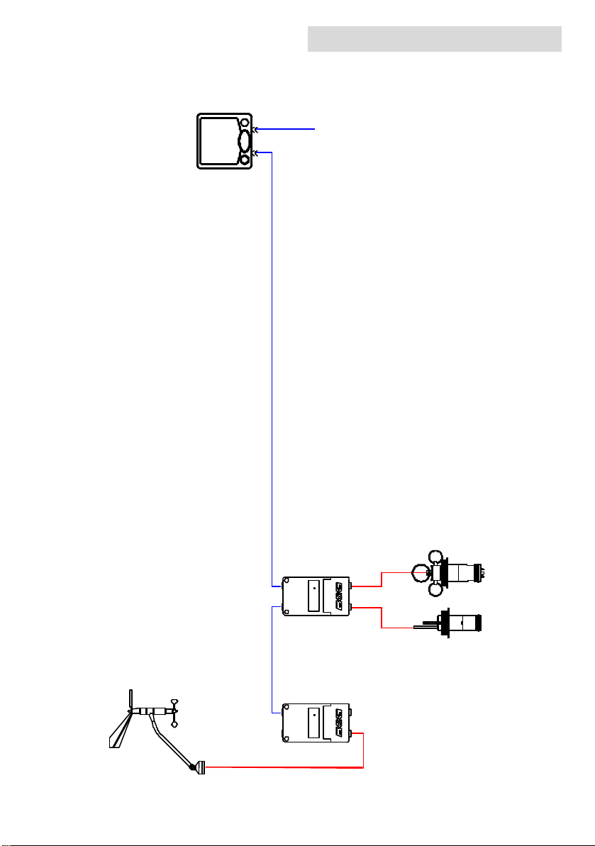
System overview
12 Volts
LCD Display
10m Fastnet Cable2m Fastnet Cable
Speed Depth
Interface Box
Speed
Depth
Masthead Unit
Page 5
Wind
Interface Box
Sensor
Sensor
overview
h1000
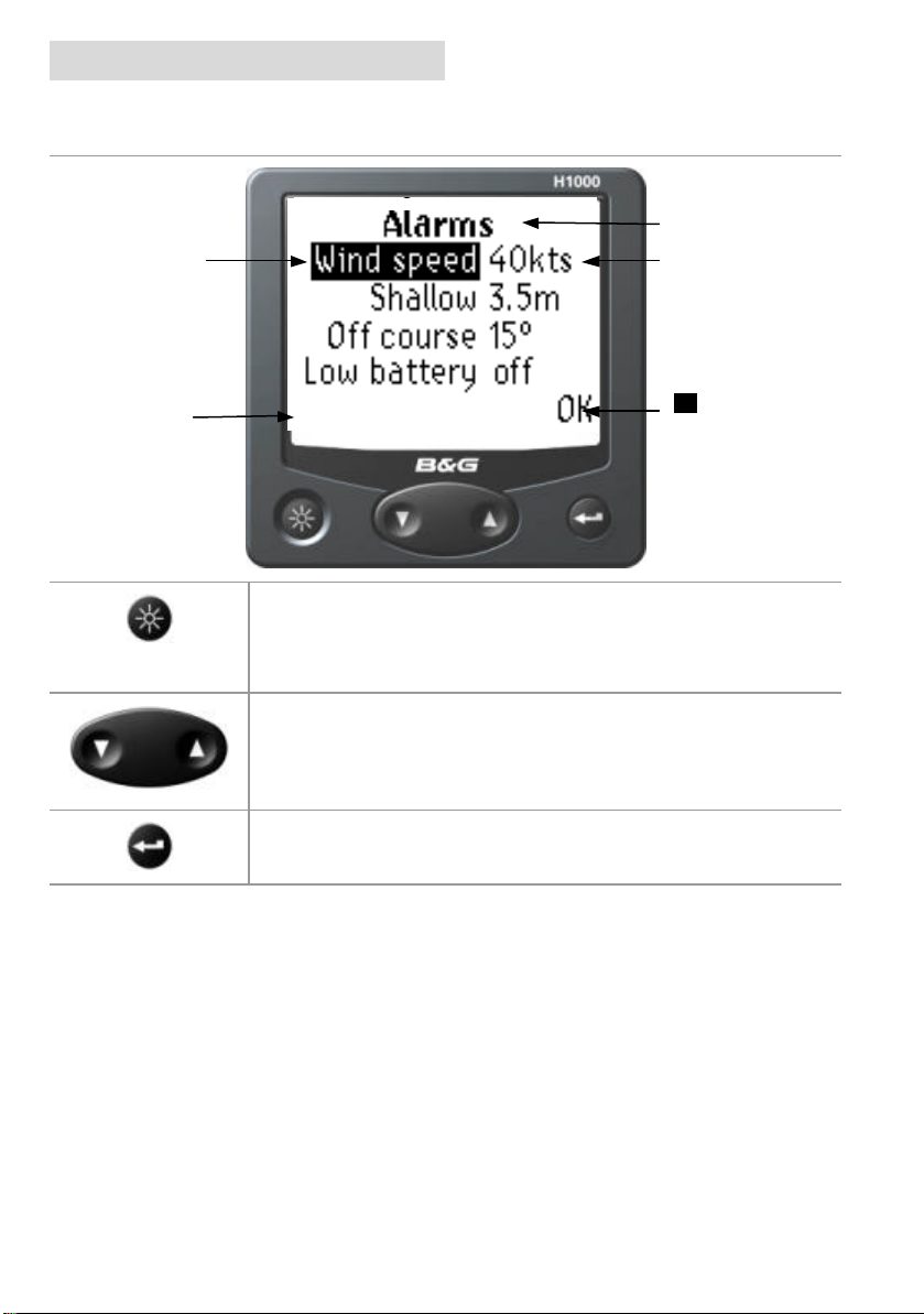
Title Line
Highlighted
Menu Item
Additional
commands are
OK returns to
display overview
Data Entry Field
displayed here
previous menu
when highlighted
light controls
The lighting level can be changed at any time by pressing the LIGHTS key.
This causes the lighting level to cycle in the sequence high - medium -
low - off and then back to high.
The UP/DOWN Keys are used to move through the various display pages
and to scroll through options
Pressing the ENTER key displays the Main Menu, it is also used to select
highlighted items.
Page 6
h1000
getting started
Before switching the h1000 on, check that the
switching on and off
installation instructions detailed on pages 26 & 27
have been correctly followed.
switching On
Turning on the 12 Volt power supply to the System you
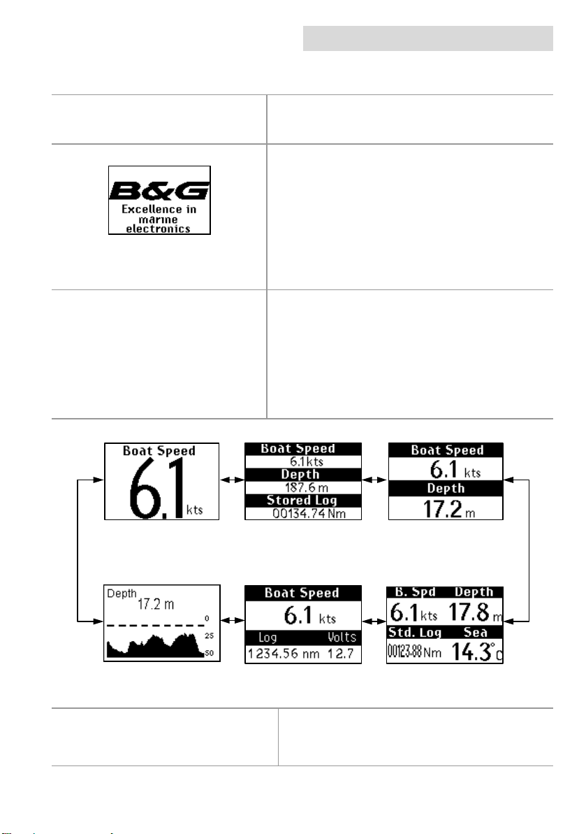
will be presented with the B&G logo splash screen.
The h1000 will then perform a short self test
procedure that checks internal memory and displays
any failure detected on the screen.
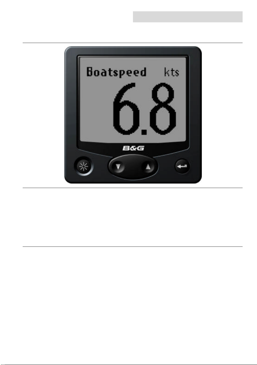
After a few seconds, the screen will display a data
page, from here you can move through the page
options using the UP/DOWN Keys.
default data pages
The h1000 displays are pre -programmed with six
default data page formats. These can be accessed by
pressing the UP/DOWN Keys. To change the default
data page settings, refer to changing display format on
Page 7 of this manual. The flexibility of the h1000
system allows an endless combination of display
formats to suit individual needs.
s t s t
Stored Log
s t
s t
s t
s t
examples of the default data pages
Page 7
Switching Off
Turning off the 12 Volt power supply will power off
the h1000 System.
getting started
h1000
fault factory settings
Language: English
Speed/Distance Units: Nautical Miles
Depth Units: Metres
Wind Speed Units: Knots
Bearing Reference: Magnetic
Date Format: Day-Month-Year
Time Reference: UTC (universal time coordinate)
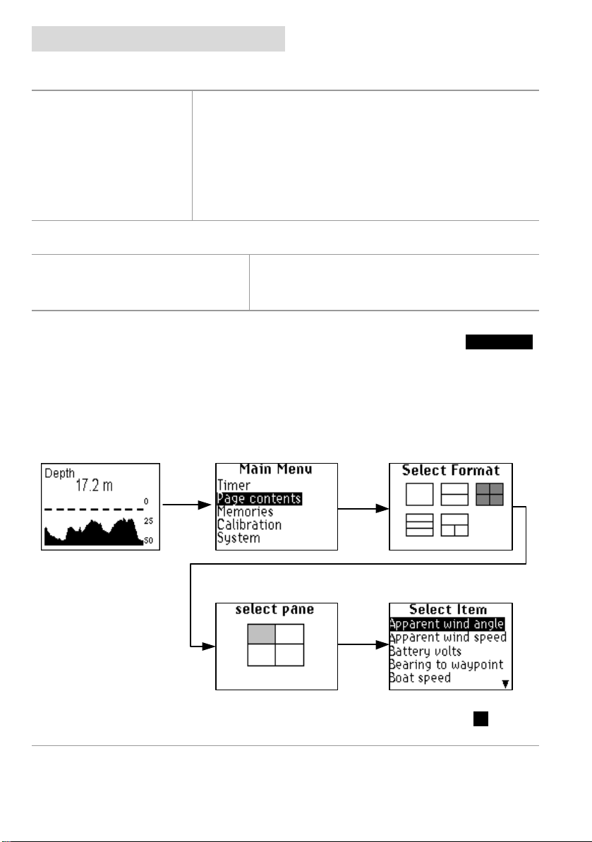
changing display format
changing pages
Pressing the ENTER key from a data page will display the main menu. Select the Page Contents
menu to change the format of the data page previously displayed.
Select one of the pre -defined display formats using the UP/DOWN keys and then press ENTER to
select.
Once a display format has been selected, you can then choose which information is displayed in
each panel. Use the UP/DOWN keys to scroll through the choices and then press the ENTER key to
select.
display formats
The display can be customised for personal
preferences using the page contents menu.
Repeat the selection process until you have made a choice for each pane. Highlight OK and press
the ENTER key to save. You will then be taken back to the Main Menu.
Page 8
h1000
getting started
graphical pages
graphical pages
There are four full screen graphical pages available
when the appropriate data is on the system.
These pages are viewed by selecting Page Contents
from the Main Menu, and then selecting the Full
Screen option from the Select Format page.
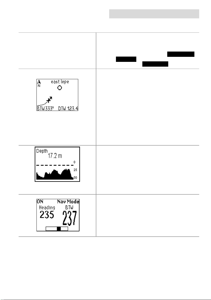
track screen
Available when a GPS is part of the system and
currently navigating to an active waypoint.
The track screen shows the Vessel’s position on the
screen as an XX, the arrow from the vessel’s position
shows the current course over ground to the next
waypoint of the leg.
The relative position of the waypoint is shown as a
circle. The name of the waypoint, the bearing to
waypoint (BTW) and distance to waypoint (DTW)
information are also displayed. The position of this
information depends on the direction of the vessel.
depth
Available when a Depth sensor is part of the system.
Depth is clearly shown in figures in the top half of the
screen.
The histogram in the lower half the screen gives an
impression of the profile of the seabed.
A dashed line shows the minimum depth alarm level, if
set.
pilot display
Available when a Pilot is part of the system.
This is a read-only repeat of the main page on the pilot
display unit.
The layout of this page will depend on the mode
currently selected by the pilot. Refer to the h1000 Pilot
User manual for more details.
Page 9
main menu
h1000
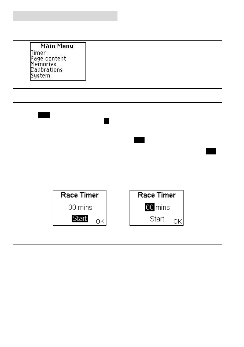
main menu
menu system
From any data page, press the ENTERENTER key to access
the h1000 menu system. The Main MenuMain Menu will be
displayed.
If no other key is pressed within a period of six
seconds, the display will revert to the previously
displayed data page.
timer
timer
When the timer is selected from the Main Menu for the first time, the display will show Time to
Start. To adjust the start time, highlight 00 mins and press the ENTER key when ready. Alter the
countdown start time by using the UP/DOWN keys and press the ENTER key to move between the
digits.
To start the timer, use the UP/DOWN keys to highlight Start and press the ENTER key when ready.
If the timer is counting down to the start of a race, the Title will remain as Time to Start. When the
timer reaches zero, the title will change to Elapsed Time and continue counting up until Reset is
selected.
The timer function continues to operate even when the timer page is exited. This allows access to
other pages if necessary or perhaps even configure a data page to show the Race timer function.
Page 10
 Loading...