

B&G DAR-04 Installation And Operation Manual
PLEASE READ BEFORE USING THE EQUIPMENT
EN 2.0
INSTALLATION AND OPERATION MANUAL
English
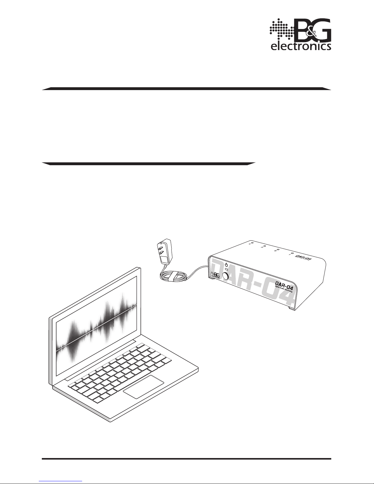
DAR-04
Digital Audio Recording System
& Digital Audio Recording Software
DAR-04 Digital Audio Recording System DAR-04 Digital Audio Recording System
2 3
INTRODUCTION
DAR (Digital Audio Recording system) has the capability to record and process conversations,
executing a digital audio processing to deliver a higher quality.
DAR records conversations from 1 to 4 audio inputs simultaneously and stores them in an
internal memory. All the conversations are stored during a week time for each audio input
and, once the maximum storage capacity has been reached, it starts to rewrite the oldest
recordings rst, and so it records in a continuous loop. The equipment accepts different
audio input devices, such as B&G microphones or B&G intercoms.
DAR can be set to record at specic time schedules; otherwise, DAR records continuously by
default, even when the intercoms are off.
The equipment includes a software for recording management, where the recorded audios
can be ltered by date, played, and downloaded. For the equipment and software to function,
both the DAR and the computer executing the software need to be connected to the same
computer network (LAN).
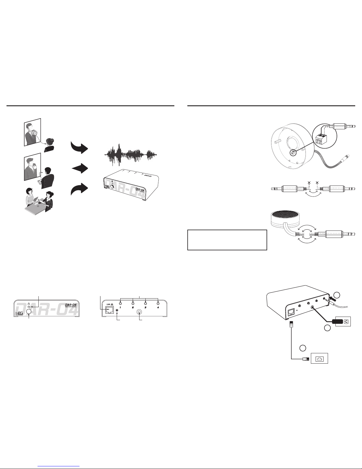
Part diagram
Power indicator
Power button
Audio input connectors
Power connection
Network connection
Reset
INSTALLATION
Before installing the DAR, make sure that the audio input device to plug in (intercom or
microphone) is properly installed and operational.
Depending on the input device to connect with the DAR, locate the audio wires and perform
all the required junctions, as explained on the next page.
If the wire’s length is sucient for the installation space, connect them directly to the DAR;
otherwise, add more wire and do all the jointing. Take the recommendations into account to
avoid affecting the input device’s correct operation.
Connection instructions according to the input device
Connection to LTG intercom
Plug the wires into the terminal as shown
in the gure.
Adjust the wires with the terminal screws,
leaving some slack wire.
SHIELD
RED
Connection to LTC intercom
Join and weld the wires as shown in the
gure. Insulate the wires upon nishing.
D
L
E
I
H
S
D
E
R
WHITEWHITE
Connection to Microphone
Join and weld the wires as shown in the
gure. Insulate the wires upon nishing.
D
L
E
I
H
S
S
H
I
E
L
D
D
E
R
W
H
I
T
E
NOTE: Avoid connecting the red’s
shield to the white’s shield to prevent
introducing noise into the recordings.
Once you have done all the needed wire joints, follow the installation procedure.
Installation procedure
When selecting the place where the DAR electronic unit is to be installed, make sure that
there is a nearby network point.
1. Connect the 3.5 mm stereo plug
coming from the audio input (LTG,
LTC or microphone) into one of the
DAR’s audio connectors.
2. Connect the UTP cable to the nearest
LAN port.
3. Connect the 5VDC power adapter to a
110 or 220VAC power outlet.
4. To turn on the equipment, press and
hold the power button (5 s) until the
power indicator blinks. The power
indicator will stop blinking once the
DAR has started up correctly.
5. To turn off the equipment, press and
hold the power button (5 s).
110V / 220V
AC
LAN
Network
RJ-45
1
2
3
 Loading...