

BFT ZARA BTL2 Installation Manual

ZARA BTL2
D812059 00100_02 31-10-14
ZARA BTL2
QUADRO COMANDO
CONTROL PANEL
CENTRALE DE COMMANDE
SELBSTÜBERWACHENDE STEUERUNG
CUADRO DE MANDOS
BEDIENINGSPANEEL
ISTRUZIONI DI INSTALLAZIONE
INSTALLATION MANUAL
INSTRUCTIONS D’INSTALLATION
MONTAGEANLEITUNG
INSTRUCCIONES DE INSTALACION
INSTALLATIEVOORSCHRIFTEN
Attenzione! Leggere attentamente le “Avvertenze” all’interno! Caution! Read “Warnings” inside carefully! Attention! Veuillez lire attentivement les Avertissements qui se trouvent à l’intérieur! Achtung! Bitte lesen Sie
aufmerksam die „Hinweise“ im Inneren! ¡Atención¡ Leer atentamente las “Advertencias”en el interior! Let op! Lees de “Waarschuwingen”tigre aan de binnenkant zorgvuldig!
www.BFTGateOpeners.com | (800) 878-7829

2 - ZARA BTL2
D812059 00100_02
A
C
0,75
0,75
0,75
0,75
*
*
3x2,5 mm
2
*
3x2,5 mm
2
D
JP3
725150 70
24V ~
2
1
TX1
2
1
RX1
4
5
3
DIP 3 = OFF
ELS
Y #
F2 4 AT
F1 1.25 AT(220-230V)
F1 2.5 AT (120V)
ANT.
ANT
SHIELD
230V
(*)
24V
(*) 110V
220
S4
T1 T2 T3
T4
PWR ON
FLT2
FLT1
PHOT
STOP
OPEN
START
SW02
SW01
SWC2
SWC1
BAR
10
11
M1
14 15
20
21
28 29
40
41
42
43
44
45 50
51
52
60 61
62
70
71
72
73
74 75
M2
24V
24V -
24V +
24 VSafe+
COM
NO
NO
NC
NC
NC
24V-max15W
max 25W
SW2
-
+
-
+
SW1
JP5 JP2
JP4
+
+
+
+
S3
X1
START
S3
X1
STOP
START
L N
L
N
220-230V ~
*
START
OPEN
COM
PHOT
STOP
FAULT 1
BAR
FAULT 2
S1
S2
S3
RADIO
EER
SET
INSTALLAZIONE VELOCE-QUICK INSTALLATION
INSTALLATION RAPIDE
- INSTALACIÓN RÁPIDA
PREDISPOSIZIONE TUBI, TUBE ARRANGEMENT, PRÉDISPOSITION DES TUYAUX, VORBEREITUNG DER LEITUNGEN,
DISPOSICIÓN DE TUBOS, VOORBEREIDING LEIDINGEN.
Vedere specica motore
See motor specications
Consultez les caractéristiques du moteur
Siehe Motordaten
Véase especicaciones motor
Zie motorspecicatie
Antenna
Antenne
Antena
Antenne
Sicurezze
Safety devices
Sécurités
Sicherheitsvorrichtungen
Dispositivos de seguridad
Veiligheden
Collegamento di 1 coppia di fotocellule non vericate
Connection of 1 pair of non-tested photocells
Connexion 1 paire photocellules no vériées
Anschluss von einem Paar nicht überprüften Fotozellen
Conexión de 1 par fotocélulas no comprobadas
Aansluiting van 1 paar fotocellen anders dan “trusted device”
Comandi / Commands
Commandes/Bedienelemente
Mandos/ Commando’s
Alimentazione accessori
Accessories power supply
Alimentation des accessoires
Stromversorgung Zubehör
Alimentación accesorios
Voeding accessoires
Ingressi necorsa
Limit switch inputs
Entrées des ns de course
Eingänge Anschlag
Entradas nales de carrera
Ingangen
Elettroserratura / Solenoid lock
Serrure électrique / Elektroschloss
Cerradura eléctrica / Elektrisch slot
Lampeggiante / Blinker / Clignotant
Warnblinkleuchte / Bombilla / Knipperlicht
Motore / Motor / moteur
Motor /Eindaanslag/Encoder
Altre tensioni disponibili a richiesta
Other voltages available on request
Autres tensions disponibles sur demande
Weitere Spannungen auf Anfrage erhältlich
Otras tensiones disponibles a petición
Andere spanningen op aanvraag beschikbaar

ZARA BTL2 - 3
D812059 00100_02
ENGLISH FRANÇAIS ESPAÑOL
NEDERLANDS
DEUTSCHITALIANO
E
F
START
OK
S1
S1
S1
x1
S1 S2 S3
RADIO RADIO RADIO
=
5s
S1 S2 S3
S2S1 S3
SET
S2S1 S3
SET
S2S1 S3
SET
OK KO
AUTO OPEN
AUTO CLOSE
AUTO OPEN
AUTO CLOSE
G
A
B
MEMORIZZAZIONE RADIOCOMANDO/MEMORIZING REMOTE CONTROLS/MÉMORISATION RADIOCOMMANDE
ABSPEICHERUNG DER FERNBEDIENUNG /MEMORIZACIÓN DEL RADIOMANDO/MEMORIZAÇÃO DO RADIOCOMANDO
LEGENDA - KEY - LÉGENDE - LEGENDE - LEYENDA - LEGENDA
Fisso
Steadily lit
Fixe
Ununterbrochen an
Fijo
Continu
Lampeggio continuo
Continuous ashing
Clignotement continu
Kontinuierliches Blinken
Parpadeo continuo
Continu knipperen
Lampeggio intermittente
Intermittent ashing
Clignotement intermittent
intermittierendes Blinken
Parpadeo intermitente
Met intervallen knipperen
REGOLAZIONE AUTOSET, ADJUSTING AUTOSET
RÉGLAGE AUTOSET , EINSTELLUNG AUTOSET
REGULACIÓN AUTOSET, REGULAÇÃO AUTOSET.

4 - ZARA BTL2
D812059 00100_02
H
50
51
52
70
71
72
73
74 75
24V -
24V +
24 VSafe+
COM
PHOT
BAR
STOP
FAULT 1
FAULT 2
NC
NC
NC
PHOT
1
2
1
2
3
4
5
51
TX1 RX1
1
2
1
2
3
4
5
52
50
TX1 RX1
1
2
1
2
3
4
5
TX1 RX1
1
2
1
2
3
4
5
TX2 RX2
1
2
1
2
3
4
5
TX1 RX1
1
2
1
2
3
4
5
TX1 RX1
1
2
1
2
3
4
5
TX1 RX1
1
2
1
2
3
4
5
TX2 RX2
1 PHOT / 1 PHOT CL
1 PHOT / 1 PHOT CL
2 PHOT / 2 PHOT CL
BAR 8K2
50
52
50
52
50
51
50
51
50
51
50
51
50
70
72
70
72
73
70
70
72
73
BAR
Bar 1
1
2
3
4
5
6
Bar 1
1
2
3
4
5
Bar 2
1
2
3
4
5
Bar 1
1
2
3
4
5
6
6
6
Bar 1
1
2
3
4
5
6
Bar 1
1
2
3
4
5
Bar 2
1
2
3
4
5
Bar 1
1
2
3
4
5
6
6
6
BAR 8K2
1 BAR
1 BAR
2 BAR
51
51
50
51
50
51
50
52
52
52
74
70
74
70
75
74
70
51
50
70
75
70
74
8,2Kohm 5%
SAFETY EDGE
SAFETY EDGE
DIP2 OFF
DIP4 OFFDIP4 ON
DIP2 ON
DIP3 OFFDIP3 ON
1
2
3
4
5

ZARA BTL2 - 5
D812059 00100_02
ITALIANO
MANUALE PER L’INSTALLAZIONE
AVVERTENZE PER L’INSTALLATORE
Tutto quello che non è espressamente previsto nel manuale d’installazione, non è permesso. ll buon funzionamento dell’operatore è garantito
solo se vengono rispettati i dati riportati. La ditta non risponde dei danni
causati dall’inosservanza delle indicazioni riportate in questo manuale.
Lasciando inalterate le caratteristiche essenziali del prodotto, la Ditta
si riserva di apportare in qualunque momento le modiche che essa
ritiene convenienti per migliorare tecnicamente, costruttivamente
e commercialmente il prodotto, senza impegnarsi ad aggiornare la
presente pubblicazione.
ATTENZIONE! Importanti istruzioni di sicurezza. Leggere e seguire attentamente tutte le avvertenze e le istruzioni che accompagnano il prodotto
poiché un’installazione errata può causare danni a persone, animali o cose.
Le avvertenze e le istruzioni forniscono importanti indicazioni riguardanti la
sicurezza, l’installazione, l’uso e la manutenzione. Conservare le istruzioni
per allegarle al fascicolo tecnico e per consultazioni future.
SICUREZZA GENERALE
Questo prodotto è stato progettato e costruito esclusivamente per l’utilizzo
indicato in questa documentazione. Usi diversi da quanto indicato potrebbero
essere causa di danni al prodotto e di pericolo.
- Gli elementi costruttivi della macchina e l’installazione devono essere in accordo
con le seguenti Direttive Europee, ove applicabili: 2004/108/CE, 2006/95/CE,
2006/42/CE, 89/106/CE, 99/05/CE e loro modiche successive. Per tutti i Paesi
extra CEE, oltre alle norme nazionali vigenti, per un buon livello di sicurezza è
opportuno rispettare anche le norme citate.
- La Ditta costruttrice di questo prodotto (di seguito “Ditta”) declina qualsiasi
responsabilità derivante da un uso improprio o diverso da quello per cui è
destinato e indicato nella presente documentazione nonché dall’inosservanza
della Buona Tecnica nella costruzione delle chiusure (porte, cancelli, ecc.) e dalle
deformazioni che potrebbero vericarsi durante l’uso.
- L’installazione deve essere eseguita da personale qualicato (installatore professionale, secondo EN12635), nell’osservanza della Buona Tecnica e delle norme
vigenti.
- Prima di installare il prodotto apportare tutte le modiche strutturali relative
alle realizzazione dei franchi di sicurezza a alla protezione o segregazione di
tutte le zone di schiacciamento, cesoiamento, convogliamento e di pericolo in
genere, secondo quanto previsto dalle norme EN 12604 ed 12453 o eventuali
norme locali di installazione. Vericare che la struttura esistente abbia i necessari
requisiti di robustezza e stabilità.
- Prima di iniziare l’installazione vericare l’integrità del prodotto.
- La Ditta non è responsabile della inosservanza della Buona Tecnica nella costruzione e manutenzione degli inssi da motorizzare, nonché delle deformazioni
che dovessero intervenire nell’utilizzo.
- Vericare che l’intervallo di temperatura dichiarato sia compatibile con il luogo
destinato all’installazione dell’automazione.
- Non installare questo prodotto in atmosfera esplosiva: la presenza di gas o fumi
inammabili costituisce un grave pericolo per la sicurezza.
- Togliere l’alimentazione elettrica, prima di qualsiasi intervento sull’impianto.
Scollegare anche eventuali batterie tampone se presenti.
- Prima di collegare l’alimentazione elettrica, accertarsi che i dati di targa corrispondano ai quelli della rete di distribuzione elettrica e che a monte dell’impianto
elettrico vi siano un interruttore dierenziale e una protezione da sovracorrente
adeguati. Prevedere sulla rete di alimentazione dell’automazione, un interruttore
o un magnetotermico onnipolare che consenta la disconnessione completa nelle
condizioni della categoria di sovratensione III.
- Vericare che a monte della rete di alimentazione, vi sia un interruttore dierenziale con soglia non superiore a 0.03A e a quanto previsto dalle norme vigenti.
- Vericare che l’impianto di terra sia realizzato correttamente: collegare a terra
tutte le parti metalliche della chiusura (porte, cancelli, ecc.) e tutti i componenti
dell’impianto provvisti di morsetto di terra.
- L’installazione deve essere fatta utilizzando dispositivi di sicurezza e di comandi
conformi alla EN 12978 e EN12453.
- Le forze di impatto possono essere ridotte mediante l’utilizzo di bordi deformabili.
- Nel caso in cui le forze di impatto superino i valori previsti dalle norme, applicare
dispositivi elettrosensibili o sensibili alla pressione.
- Applicare tutti i dispositivi di sicurezza (fotocellule, coste sensibili, ecc.) necessari
a proteggere l’area da pericoli di impatto, schiacciamento, convogliamento,
cesoiamento. Tenere in considerazione le normative e le direttive in vigore,
i criteri della Buona Tecnica, l’utilizzo, l’ambiente di installazione, la logica di
funzionamento del sistema e le forze sviluppate dall’automazione.
- Applicare i segnali previsti dalle normative vigenti per individuare le zone
pericolose (i rischi residui). Ogni installazione deve essere identicata in modo
visibile secondo quanto prescritto dalla EN13241-1.
- Successivamente al completamento dell’installazione, applicare una targa
identicativa della porta/cancello
- Questo prodotto non può essere installato su ante che incorporano delle porte
(a meno che il motore sia azionabile esclusivamente a porta chiusa).
- Se l’automazione è installata ad una altezza inferiore a 2,5 m o se è accessibile,
è necessario garantire un adeguato grado di protezione delle parti elettriche e
meccaniche.
- Installare qualsiasi comando sso in posizione tale da non causare pericoli e
lontano da parti mobili. In particolare i comandi a uomo presente devono essere
posizionati in vista diretta della parte guidata, e, a meno che non siano a chiave,
devono essere installati a una altezza minima di 1,5 m e in modo tale da non
essere accessibili al pubblico.
- Applicare almeno un dispositivo di segnalazione luminosa (lampeggiante) in
posizione visibile, ssare inoltre alla struttura un cartello di Attenzione.
- Fissare in modo permanente una etichetta relativa al funzionamento dello sblocco
manuale dell’automazione e apporla vicino all’organo di manovra.
- Assicurarsi che durante la manovra siano evitati o protetti i rischi meccanici ed
in particolare l’impatto, lo schiacciamento, il convogliamento, il cesoiamento tra
parte guidata e parti circostanti.
- Dopo aver eseguito l’installazione, assicurarsi che il settaggio dell’automazione
motore sia correttamente impostato e che i sistemi di protezione e di sblocco
funzionino correttamente.
- Usare esclusivamente parti originali per qualsiasi manutenzione o riparazione.
La Ditta declina ogni responsabilità ai ni della sicurezza e del buon funziona-
mento dell’automazione se vengono impiegati componenti di altri produttori.
- Non eseguire alcuna modica ai componenti dell’automazione se non espressamente autorizzata dalla Ditta.
- Istruire l’utilizzatore dell’impianto per quanto riguarda gli eventuali rischi residui,
i sistemi di comando applicati e l’esecuzione della manovra apertura manuale
in caso di emergenza: consegnare il manuale d’uso all’utilizzatore nale.
- Smaltire i materiali di imballo (plastica, cartone, polistirolo, ecc.) secondo quanto
previsto dalle norme vigenti. Non lasciare buste di nylon e polistirolo alla portata
dei bambini.
COLLEGAMENTI
ATTENZIONE! Per il collegamento alla rete utilizzare: cavo multipolare di sezione
minima 5x1,5mm
2
o 4x1,5mm2 per alimentazioni trifase oppure 3x1,5mm2 per
alimentazioni monofase (a titolo di esempio, il cavo può essere del tipo H05 VV-F
con sezione 4x1.5mm2). Per il collegamento degli ausiliari utilizzare conduttori
con sezione minima di 0,5 mm2.
- Utilizzare esclusivamente pulsanti con portata non inferiore a 10A-250V.
- I conduttori devono essere vincolati da un ssaggio supplementare in prossi-
mità dei morsetti (per esempio mediante fascette) al ne di tenere nettamente
separate le parti in tensione dalle parti in bassissima tensione di sicurezza.
-
Il cavo di alimentazione, durante l’installazione, deve essere sguainato in modo da
permettere il collegamento del conduttore di terra all’appropriato morsetto lasciando
però i conduttori attivi il più corti possibile. Il conduttore di terra deve essere l’ultimo
a tendersi in caso di allentamento del dispositivo di ssaggio del cavo.
ATTENZIONE! i conduttori a bassissima tensione di sicurezza devono essere
sicamente separati dai conduttori a bassa tensione.
L’accessibilità alle parti in tensione deve essere possibile esclusivamente per il
personale qualicato (installatore professionale)
VERIFICA DELL’AUTOMAZIONE E MANUTENZIONE
Prima di rendere denitivamente operativa l’automazione, e durante gli interventi
di manutenzione, controllare scrupolosamente quanto segue:
- Vericare che tutti i componenti siano ssati saldamente;
- Vericare l’operazione di avvio e fermata nel caso di comando manuale.
- Vericare la logica di funzionamento normale o personalizzata.
-
Solo per cancelli scorrevoli: vericare il corretto ingranamento cremagliera pignone con un gioco di 2 mm lungo tutta la cremagliera; tenere la rotaia di
scorrimento sempre pulita e libera da detriti.
-Solo per cancelli e porte scorrevoli: vericare che il binario di scorrimento del
cancello sia lineare, orizzontale e le ruote siano idonee a sopportare il peso del
cancello.
-Solo per cancelli scorrevoli sospesi (Cantilever): vericare che non ci sia abbas-
samento o oscillazione durante la manovra.
-Solo per cancelli a battente: vericare che l’asse di rotazione delle ante sia
perfettamente verticale.
- Solo per barriere: prima di aprire la portina la molla deve essere scarica
(asta verticale).
- Controllare il corretto funzionamento di tutti i dispositivi di sicurezza (fotocellule,
coste sensibili, ecc) e la corretta regolazione della sicurezza antischiacciamento
vericando che il valore della forza d’impatto misurato nei punti previsti dalla
norma EN 12445, sia inferiore a quanto indicato nella norma EN 12453.
- Le forze di impatto possono essere ridotte mediante l’utilizzo di bordi deformabili.
- Vericare la funzionalità della manovra di emergenza ove presente.
- Vericare l’operazione di apertura e chiusura con i dispositivi di comando applicati.
- Vericare l’integrità delle connessioni elettriche e dei cablaggi, in particolare lo
stato delle guaine isolanti e dei pressa cavi.
- Durante la manutenzione eseguire la pulizia delle ottiche delle fotocellule.
- Per il periodo di fuori servizio dell’automazione, attivare lo sblocco di emergenza
(vedi paragrafo “MANOVRA DI EMERGENZA”) in modo da rendere folle la parte
guidata e permettere così l’ apertura e la chiusura manuale del cancello.
- Se il cavo di alimentazione è danneggiato, esso deve essere sostituito dal co-
struttore o dal suo servizio di assistenza tecnica o comunque da una persona
con qualica similare, in modo da prevenire ogni rischio.
- Se si si installano dispositivi di tipo “D” (come deniti dalla EN12453), collegati
in modalità non vericata, prescrivere una manutenzione obbligatoria con
frequenza almeno semestrale.
- La manutenzione come sopra descritta deve essere ripetuta con frequenza
almeno annuale o ad intervalli di tempo minori qualora le caratteristiche del
sito o dell’installazione lo richiedessero.
ATTENZIONE!
Ricordarsi che la motorizzazione è una facilitazione dell’uso del cancello/porta e non
risolve problemi a difetti e decienze di installazione o di mancata manutenzione.
DEMOLIZIONE
L’eliminazione dei materiali va fatta rispettando le norme vigenti. Non
gettate il vostro apparecchio scartato, le pile o le batterie usate nei
riuti domestici. Avete la responsabilità di restituire tutti i vostri riuti
da apparecchiature elettriche o elettroniche lasciandoli in un punto di
raccolta dedicato al loro riciclo.
SMANTELLAMENTO
Nel caso l’automazione venga smontata per essere poi rimontata in altro sito bisogna:
- Togliere l’alimentazione e scollegare tutto l’impianto elettrico.
- Togliere l’attuatore dalla base di ssaggio.
- Smontare tutti i componenti dell’installazione.
- Nel caso alcuni componenti non possano essere rimossi o risultino danneggiati,
provvedere alla loro sostituzione.
LA DICHIARAZIONE DI CONFORMITÀ PUÒ ESSERE CONSULTATA SUL SITO:
WWW.BFT.IT NELLA SEZIONE PRODOTTI.
AVVERTENZE PER L’INSTALLATORE D811766_12

6 - ZARA BTL2
D812059 00100_02
MANUALE PER L’INSTALLAZIONE
1) GENERALITÁ
Il quadro comandi ZARA BTL2 viene fornito dal costruttore con settaggio standard.
Qualsiasi variazione, deve essere impostata mediante congurazione dei TRIMMER
e DIP SWITCH.
Supporta completamente il protocollo EELINK.
Le caratteristiche principali sono:
- Controllo di 1 o 2 motori 24V BT
Nota: Devono essere utilizzati 2 motori dello stesso tipo.
- Regolazione elettronica della coppia con rilevamento ostacoli
- Ingressi separati per le sicurezze
- Ricevitore radio incorporato rolling-code con clonazione trasmettitori.
La scheda è dotata di una morsettiera di tipo estraibile per rendere più agevole
la manutenzione o la sostituzione. Viene fornita con una serie di ponti precablati
per facilitare l’installatore in opera.
I pon ti ri guard ano i mor setti : 70-71, 70-72, 70-74. Se i morsetti sopraindicati
vengono utilizzati, togliere i rispettivi ponti.
VERIFICA
Il quadro
ZARA BTL2
eettua il controllo (verica) dei relè di marcia e dei dispo-
sitivi di sicurezza (fotocellule), prima di eseguire ogni ciclo di apertura e chiusura.
In caso di malfunzionamenti vericare il regolare funzionamento dei dispositivi
collegati e controllare i cablaggi.
2) DATI TECNICI
Alimentazione 220-230V 50/60 Hz*
Isolamento rete/bassa tensione > 2MOhm 500V
Temperatura di funzionamento -20 / +55°C
Protezione termica Software
Rigidità dielettrica rete/bt 3750V~ per 1 minuto
Corrente di commutazione relè motore
10A
Potenza massima motori 40W + 40W (24V
)
Alimentazione accessori
24V ~ (0,2A assorbimento max)
24V ~ safe
Elettroserratura 24V ~ 15W max
Lampeggiante 24V 25W max
Fusibili vedi Fig. C
N° combinazioni 4 miliardi
N° max radiocomandi memorizzabili
63
Tempo lavoro massimo 3 minuti
Potenza massima 130W
Ciclo massimo S3 13s -1-13s-1x30
pausa
90 min.
(* altre tensioni disponibili a richiesta)
Versioni trasmettitori utilizzabili:
Tutti i trasmettitori ROLLING CODE compatibili con
3) PREDISPOSIZIONE TUBI Fig. A
Predisporre l’impianto elettrico facendo riferimento alle norme vigenti per gli
impianti elettrici CEI 64-8, IEC364, armonizzazione HD384 ed altre norme nazionali.
4) COLLEGAMENTI MORSETTIERA Fig. C
AVVERTENZE - Nelle operazioni di cablaggio ed installazione riferirsi alle norme
vigenti e comunque ai principi di buona tecnica.
I conduttori alimentati con tensioni diverse, devono essere sicamente separati,
oppure devono essere adeguatamente isolati con isolamento supplementare
di almeno 1mm.
I conduttori devono essere vincolati da un ssaggio supplementare in prossimità
dei morsetti, per esempio mediante fascette.
Tutti i cavi di collegamento devono essere mantenuti adeguatamente lontani
dal dissipatore.
ATTENZIONE! Per il collegamento alla rete, utilizzare cavo multipolare di
sezione minima 3x1.5mm
2
e del tipo previsto dalle normative vigenti.
Per il collegamento dei motori, utilizzare cavo di sezione minima 1,5 mm
2
e del tipo previsto dalle normative vigenti. A titolo di esempio, se il cavo
è all’esterno (all’aperto), deve essere almeno pari a H07RN-F mentre, se
all’interno (in canaletta), deve essere almeno pari a H05 VV
Morsetto Denizione Descrizione
Alimentazione
L FASE
Alimentazione monofase
220-230V ~ 50/60 Hz*
N NEUTRO
JP2
PRIM TRASF
Collegamento primario trasformatore, 220-230V ~
*
JP5
JP4 SEC TRASF
Alimentazione scheda:
24V~ Secondario trasformatore
24V= Alimentazione da batteria tampone
Motore
10 MOT 1 +
Collegamento motore 1. Sfasamento ritardato in chiusura. (T4)
11 MOT 1 14 MOT 2 +
Collegamento motore 2. Sfasamento ritardato in apertura. 2s
15 MOT 2 -
Aux
20
Lampeggiante
24V
(1A MAX)
Uscita lampeggiante 24V max 25W. Il contatto rimane chiuso durante la movimentazione dell’anta .
21
28
Elettroserratura
24V ~ 15W max
29
Finecorsa
40 Non utilizzato
41 Non utilizzato
42 SW1 Finecorsa motore 1
43 SW2 Finecorsa motore 2
44 Non utilizzato
45 Non utilizzato
Alim.
Accessori
50 24V-
Uscita alimentazione accessori.
51 24V+
52 24 Vsafe+
Uscita alimentazione per dispositivi di sicurezza vericati (trasmettitore fotocellule e trasmettitore costa sensibile).
Uscita attiva solo durante il ciclo di manovra.
Comandi
60 Comune Comune ingressi START, OPEN
61 START
Pulsante di comando START (N.O.)
Funzionamento secondo logiche “3-4 PASSI”
62 OPEN
Pulsante di comando OPEN (N.O.)
Il comando esegue un’apertura. Se il l’ingresso rimane chiuso, le ante rimangono aperte no all’apertura del
contatto. A contatto aperto l’automazione chiude dopo il tempo di tca, se attivato.
Sicurezze
70 Comune Comune ingressi STOP, PHOT e BAR
71 STOP
Il comando interrompe la manovra. (N.C.)
Se non si utilizza lasciare il ponticello inserito.
72
PHOT (*
*)
Ingresso FOTOCELLULA (N.C.)
Funzionamento secondo le logiche “FOTOCELLULA/ FOTOCELLULA IN CHIUSURA”. Se non si utilizza lasciare il
ponticello inserito.
73 FAULT 1 Ingresso verica dispositivi di sicurezza collegati al PHOT.
74
BAR (*
*)
Ingresso costa sensibile BAR (N.C.).
Congurabile secondo le logiche “BAR/ 8K2”.
Il comando inverte il movimento per 2 sec.
Se non si utilizza lasciare il ponticello inserito.
75 FAULT 2 Ingresso verica dispositivi di sicurezza collegati al BAR.
Antenna
Y ANTENNA
Ingresso antenna.
Usare una antenna accordata sui 433MHz. Per il collegamento Antenna-Ricevente usare cavo coassiale RG58. La
presenza di masse metalliche a ridosso dell’antenna, può disturbare la ricezione radio. In caso di scarsa portata del
trasmettitore, spostare l’antenna in un punto più idoneo.
# SHIELD
(*) Altre tensioni disponibili a richiesta
(**) Se si si installano dispositivi di tipo “D” (come deniti dalla EN12453), collegati in modalità non vericata, prescrivere una manutenzione obbligatoria con frequenza almeno semestrale.

ZARA BTL2 - 7
D812059 00100_02
ITALIANO
MANUALE PER L’INSTALLAZIONE
5) COMANDI LOCALI Fig.C
La pressione del tasto S3 comanda uno START. Un ulteriore pressione del tasto,
mentre l’automazione è in movimento, viene comandato uno STOP.
6) DISPOSITIVI DI SICUREZZA
Nota: utilizzare solamente dispositivi di sicurezza riceventi con contatto
in libero scambio.
6.1) DISPOSITIVI VERIFICATI Fig. H
6.2) COLLEGAMENTO DI 1 COPPIA DI FOTOCELLULE NON VERIFICATE Fig. D
7) MEMORIZZAZIONE RADIOCOMANDO Fig. E
RADIO
- NOTA IMPORTANTE: CONTRASSEGNARE IL PRIMO TRASMETTITORE MEMORIZZATO CON IL BOLLINO CHIAVE (MASTER).
Il primo trasmettitore, nel caso di programmazione manuale, assegna il CODICE
CHIAVE DELLA RICEVENTE; questo codice risulta necessario per poter eettuare
la successiva clonazione dei radiotrasmettitori.
La ricevente di bordo incorporato Clonix dispone inoltre di alcune importanti
funzionalità avanzate:
• Clonazione del trasmettitore master (rolling-code o codice sso).
• Clonazione per sostituzione di trasmettitori già inseriti nella ricevente.
Per l’utilizzo di queste funzionalità avanzate fate riferimento alle istruzioni del programmatore palmare universale ed alla Guida generale programmazioni riceventi.
8) REGOLAZIONE AUTOSET Fig. F
Consente di eettuare il settaggio automatico della Coppia motori.
Se viene a mancare l’alimentazione, al ripristino l’automazione eseguirà le manovre
a velocità di autoset no all’individuazione dei ne corsa.
ATTENZIONE!! L’operazione di autoset va eettuata solo dopo aver vericato
l’esatto movimento dell’anta (apertura/chiusura) ed il corretto posizionamento
dei blocchi meccanici.
Si deve eettuare un autoset ogni volta che si modica la forza motore (T2) lo
spazio di rallentamento (T3).
ATTENZIONE! Durante la fase di autoset la funzione di rilevamento ostacoli non
è attiva, quindi l’installatore deve controllare il movimento dell’automazione e
impedire a persone e cose di avvicinarsi o sostare nel raggio di azione dell’automazione.
ATTENZIONE: i valori di coppia impostati dall’autoset sono riferiti alla forza motore
impostata durante l’autoset. Se si modica la forza motore occorre eseguire una
nuova manovra di autoset.
ATTENZIONE: vericare che il valore della forza d’impatto misurato nei punti
previsti dalla norma EN12445, sia inferiore a quanto indicato nella norma EN 12453.
Un’errata impostazione della sensibilità può creare danni apersone, animali o cose.
ELETTROSERRATURA
ATTENZIONE: Nel caso di ante di lunghezza superiore a 3m,
risulta indispensabile l’installazione di una elettroserratura.
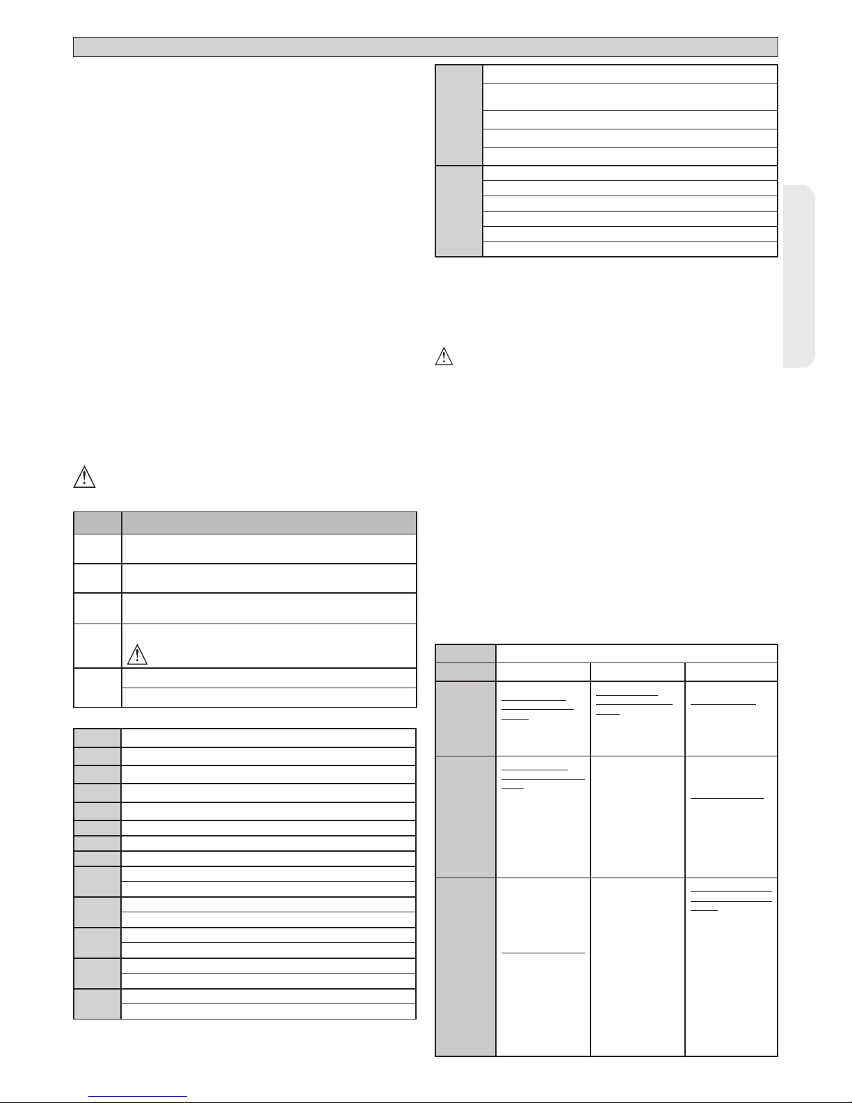
TASTI
TASTI Descrizione
S1
Aggiungi Tasto start
associa il tasto desiderato al comando Start
S2
Aggiungi Tasto pedonale
associa il tasto desiderato al comando pedonale
S2
>5s
Convalida le modiche apportate alla regolazione dei parametri e
alle logiche di funzionamento.
S1+S2
>10s
Elimina Lista
ATTENZIONE! Rimuove completamente dalla memoria della
ricevente tutti i radiocomandi memorizzati.
S3
La pressione BREVE comanda uno START.
La pressione PROLUNGATA (>5s) attiva l’ AUTOSET.
SEGNALAZIONI LEDS:
POWER
Rimane acceso: - Presenza di rete - Scheda alimentata - Fusibile
F1 integro
START
Acceso: attivazione ingresso START
OPEN
Acceso: attivazione ingresso pedonale OPEN
STOP
Spento: attivazione ingresso STOP
PHOT
Spento: attivazione ingresso fotocellula PHOT
FAULT 1
Diagnostica dell’ingresso verica sicurezze ingresso PHOT
BAR
Spento: attivazione ingresso costa BAR
FAULT 2
Diagnostica dell’ingresso verica sicurezze ingresso BAR
SWC1
Acceso: il necorsa chiusura del motore 1 è libero
Spento: Attivazione ingresso necorsa chiusura del motore 1
SWO1
Acceso: il necorsa apertura del motore 1 è libero
Spento: Attivazione ingresso necorsa apertura del motore 1
SWC2
Acceso: il necorsa chiusura del motore 2 è libero
Spento: Attivazione ingresso necorsa chiusura del motore 2
SWO2
Acceso: il necorsa apertura del motore 2 è libero
Spento: Attivazione ingresso necorsa apertura del motore 1
ERR
SPENTO: nessun errore
ACCESO: vedi tabella diagostica errori
RADIO
(VERDE)
Spento: programmazione radio disattiva
Lampeggiante solo led Radio: Programmazione radio attiva, atte-
sa tasto nascosto.
Lampeggiante sincrono con led Set: Cancellazione radiocomandi in corso
Acceso: programmazione radio attiva, attesa tasto desiderato.
Acceso 1s: attivazione canale della ricevente radio
SET
Acceso: tasto Set premuto / Autoset concluso positivamente
Triplice lampeggio: Autoset in corso
Lampeggio Veloce: Autoset Fallito
Lampeggiante sincrono con led Radio: cancellazione radiocoman-
di in corso
Acceso 1s: start/stop per attivazione tasto S3
Acceso 10s: autoset concluso correttamente
9 PROCEDURA DI REGOLAZIONE
Prima dell’accensione vericare i collegamenti elettrici.
Eseguire l’impostazione dei seguenti parametri: Tempo Chiusura Automatica,
forza motore, spazio di rallentamento .
Eseguire l’impostazione delle logiche.
Eseguire la procedura di autoset.
ATTENZIONE! Un’errata impostazione può creare danni a persone, animali
o cose.
ATTENZIONE: Verificare che il valore della forza d’impatto
misurato nei punti previsti dalla norma EN12445, sia inferiore a quanto
indicato nella norma EN 12453.
Per ottenere un risultato migliore, si consiglia di eseguire l’autoset con motori a
riposo (cioè non surriscaldati da un numero considerevole di manovre consecutive).
10) SEQUENZA VERIFICA INSTALLAZIONE
1. Eseguire la manovra di AUTOSET (*)
2. Vericare le forze di impatto: se rispettano i limiti (**) vai al punto 9 della
sequenza altrimenti
3. Adeguare eventualmente il parametro sensibilità (forza): vedi tabella parametri.
4. Rivericare le forze di impatto: se rispettano i limiti (**) vai al punto 9 della
sequenza altrimenti
5. Applicare una costa passiva
6. Rivericare le forze di impatto: se rispettano i limiti (**) vai al punto 9 della
sequenza altrimenti
7. Applicare dispositivi di protezione sensibili alla pressione o elettrosensibili (per
esempio costa attiva) (**)
8. Rivericare le forze di impatto: se rispettano i limiti (**) vai al punto 9 della
sequenza altrimenti
9. Assicurarsi che tutti i dispositivi di rilevamento presenza nell’area di manovra
funzionino correttamente
(*) Prima di eseguire l’autoset assicurarsi di avere eettuato correttamente tutte
le operazioni di montaggio e di messa in sicurezza come prescritto dalle av-
vertenze per l’installazione del manuale della motorizzazione.
(**) In funzione dell’analisi dei rischi potrebbe essere necessario comunque
ricorrere alla applicazione di dispositivi di protezione sensibili
ATTENZIONE! Un’errata impostazione può creare danni a persone, animali
o cose.
LED ERR:
Led ERR
Led SET Acceso
Lampeggiante
lento
Lampeggiante veloce
Spento
Inversione per
ostacolo, Amperostop
- Vericare eventuali ostacoli lungo il
percorso
Test Fotocellule,
Costa o Costa 8k2
fallito
- Vericare collegamento fotocellule
e/o impo stazioni
logiche
Termica
- Attendere il rareddamento dell’automazione
Acceso
Errore interno di
controllo supervisione sistema
- Provare a spegnere e riaccendere
la scheda. Se il
problema persiste
contattare l’assistenza tecnica.
Errore necorsa
- vericare collegamenti dei necorsa
Lam-
peg-
giante
lento
Errore test hardware scheda
- Vericare collegamenti al motore
- Problemi hardware alla scheda (contattare l’assistenza
tecnica)
Modicati parametri
e/o Logiche di funzionamento
- Se viene modicato lo
“spazio di rallentamento”, eseguire un nuovo
Autoset per convalidare la nuova impostazione.
- Se vengono modicati gli altri parametri o/e
le logiche di funzionamento premere per 5s
S2 per convalidare.
NOTA: L’autoset convalida comunque tutte
le modiche apportate
alla scheda

8 - ZARA BTL2
D812059 00100_02
MANUALE PER L’INSTALLAZIONE
TABELLA “A” PARAMETRI
TRIMMER Parametro
+
min.
+
max.
Descrizione
T1
Tempo chiusura
automatica [s]
0 120
Tempo di attesa prima della chiusura automatica.
NOTA: Impostare a 0 se non utilizzato.
T2 Forza ante [%] 10 100
Forza esercitata dall’anta/e. Rappresenta la percentuale di forza erogata, oltre quella memorizzata durante l’autoset (e successivamente aggiornata), prima di generare un allarme ostacolo.
ATTENZIONE: Inuisce direttamente nella forza di impatto: vericare che con il valore impostato vengano rispettate le norme di sicurezza vigenti (*). Installare se necessario dispositi-
vi di sicurezza antischiacciamento.
T3
Spazio
rallentamento
[%]
5 50
Imposta lo spazio di rallentamento in percentuale alla corsa totale. Questo spazio viene eseguito a velocità bassa.
Nota: modicando questo paramentro, va eseguito un nuovo Autoset per convalidarlo.
T4
Tempo di
ritardo chiusura
motore 1 [s]
0 25
Tempo di ritardo alla chiusura del motore 1 rispetto al motore 2.
NOTA: impostare a 0 per funzionamento un solo motore attivo (anta 1).
(*) Nell’Unione Europea applicare la EN12453 per i limiti di forza, e la EN12445 per il metodo di misura.
TABELLA “B” LOGICHE
DIP Logica Default
Barrare il settaggio
eseguito
Descrizione
1
Programmazione
radiocomandi
ON
ON
Abilita la memorizzazione via radio dei radiocomandi:
1-
Premere in sequenza il tasto nascosto e il tasto normale (T1-T2-T3-T4) di un radiocomando già memorizzato in modalità standard attraverso il menu radio.
2- Premere entro 10s il tasto nascosto ed il tasto normale (T1-T2-T3-T4) di un radiocomando da memorizzare.
La ricevente esce dalla modalità programmazione dopo 10s, entro questo tempo è
possibile inserire ulteriori nuovi radiocomandi.
Questa modalità non richiede l’accesso al quadro comando.
IMPORTANTE: Abilita l’inserimento automatico di nuovi radiocomandi, cloni e replay.
OFF
Disabilita la memorizzazione via radio dei radiocomandi e l’inserimento automatico dei
cloni. I radiocomandi vengono memorizzati solo utilizzando l’apposito menu Radio o
in automatico con i replay.
IMPORTANTE: Disabilita l’inserimento automatico di nuovi radiocomandi, cloni
2 BAR / 8K2 OFF
ON
Ingresso congurato come Bar 8k2 (Fig.H, rif.5). Ingresso per bordo resistivo 8K2.
Il comando inverte il movimento per 2 sec.
OFF
Ingresso congurato come Bar, costa sensibile (Fig.H, rif.3-4).
Il comando inverte il movimento per 2 sec.
3
Verica ingresso
fotocellula
OFF
ON
Abilita la verica delle sicurezze sull’ingresso PHOT
OFF
Verica delle sicurezze sull’ingresso PHOT non abilitata
4 Verica ingresso costa OFF
ON Abilita la verica delle sicurezze sull’ingresso BAR
OFF Verica delle sicurezze sull’ingresso BAR non abilitata.
5
Fotocellule in
chiusura
OFF
ON
In caso di oscuramento è escluso il funzionamento della fotocellula in apertura. In fase
di chiusura, inverte immediatamente.
OFF
In caso di oscuramento, le fotocellule sono attive sia in apertura che in chiusura. Un oscuramento della fotocellula in chiusura, inverte il moto solo dopo il disimpegno della fotocellula.
6 Chiusura rapida OFF
ON
Chiude dopo 3 secondi dal disimpegno delle fotocellule prima di attendere il termine
del TCA impostato
OFF Logica non attiva
7
Blocca impulsi in
apertura
OFF
ON L’impulso di start non ha eetto durante l'apertura.
OFF L’impulso di start ha eetto durante l'apertura.
8 Logica 3 passi ON
ON
Abilita la logica 3 passi, lo
start durante la fase di chiusura inverte il movimento.
3 passi 4 passi
CHIUSA
apre
apre
IN CHIUSURA stop
APERTA chiude chiude
IN APERTURA stop + TCA stop + TCA
DOPO STOP apre apre
OFF Abilita la logica 4 passi.
9
Colpo di ariete in
apertura
OFF
OFF Logica non attiva
ON
Prima di eettuare l’apertura il cancello spinge per circa 2 secondi in chiusura. Questo
consente lo sgancio più agevole dell’elettroserratura.
IMPORTANTE - In assenza di adeguati fermi d’arresto meccanici, non usare
questa funzione.
10
Pressione
necorsa chiusura
OFF
OFF
Il movimento viene fermato esclusivamente dall’intervento del necorsa di chiusura,
in questo caso è necessario provvedere ad una precisa regolazione dell’intervento del
necorsa di chiusura (Fig.G Rif.B).
ON
Da utilizzare in presenza di fermo meccanico di chiusura.
Questa funzione attiva la pressione delle ante sul fermo meccanico, senza che questo
venga considerato come ostacolo dal sensore amperostop.
Lo stelo continua quindi la sua corsa per alcuni secondi dopo l’intercettazione del
necorsa di chiusura o no all’arresto meccanico. In questo modo, anticipando leggermente l’intervento dei necorsa di chiusura, si avrà la perfetta battuta delle ante
sul fermo di arresto (Fig.G Rif.A).
ZARA BTL2 - 9
D812059 00100_02
ENGLISH
INSTALLATION MANUAL
INSTALLER WARNINGS
Anything that is not explicitly provided for in the installation manual is not allowed. The operator’s proper operation can only be
guaranteed if the information given is complied with. The Firm shall
not be answerable for damage caused by failure to comply with the
instructions featured herein.
While we will not alter the product’s essential features, the Firm reserves
the right, at any time, to make those changes deemed opportune to
improve the product from a technical, design or commercial point of
view, and will not be required to update this publication accordingly.
WARNING! Important safety instructions. Carefully read and comply with
all the warnings and instructions that come with the product as incorrect
installation can cause injury to people and animals and damage to property.
The warnings and instructions give important information regarding safety,
installation, use and maintenance. Keep hold of instructions so that you can
attach them to the technical le and keep them handy for future reference.
GENERAL SAFETY
This product has been designed and built solely for the purpose indicated herein.
Uses other than those indicated herein might cause damage to the product and
create a hazard.
- The units making up the machine and its installation must meet the requirements
of the following European Directives, where applicable: 2004/108/EC, 2006/95/
EC, 2006/42/EC, 89/106/EC, 99/05/EC and later amendments. For all countries
outside the EEC, it is advisable to comply with the standards mentioned, in addition to any national standards in force, to achieve a good level of safety.
- The Manufacturer of this product (hereinafter referred to as the “Firm”) disclaims
all responsibility resulting from improper use or any use other than that for
which the product has been designed, as indicated herein, as well as for failure
to apply Good Practice in the construction of entry systems (doors, gates, etc.)
and for deformation that could occur during use.
- Installation must be carried out by qualied personnel (professional installer,
according to EN 12635), in compliance with Good Practice and current code.
- Before installing the product, make all structural changes required to produce
safety gaps and to provide protection from or isolate all crushing, shearing and
dragging hazard areas and danger zones in general in accordance with the
provisions of standards EN 12604 and 12453 or any local installation standards.
Check that the existing structure meets the necessary strength and stability
requirements.
- Before commencing installation, check the product for damage.
- The Firm is not responsible for failure to apply Good Practice in the construction
and maintenance of the doors, gates, etc. to be motorized, or for deformation
that might occur during use.
- Make sure the stated temperature range is compatible with the site in which the
automated system is due to be installed.
- Do not install this product in an explosive atmosphere: the presence of ammable
fumes or gas constitutes a serious safety hazard.
- Disconnect the electricity supply before performing any work on the system.
Also disconnect buer batteries, if any are connected.
- Before connecting the power supply, make sure the product’s ratings match the
mains ratings and that a suitable residual current circuit breaker and overcurrent
protection device have been installed upline from the electrical system. Have
the automated system’s mains power supply tted with a switch or omnipolar
thermal-magnetic circuit breaker with a contact separation that provide full
disconnection under overvoltage category III conditions.
- Make sure that upline from the mains power supply there is a residual current
circuit breaker that trips at no more than 0.03A as well as any other equipment
required by code.
- Make sure the earth system has been installed correctly : earth all the metal parts
belonging to the entry system (doors, gates, etc.) and all parts of the system
featuring an earth terminal.
- Installation must be carried out using safety devices and controls that meet
standards EN 12978 and EN 12453.
- Impact forces can be reduced by using deformable edges.
- In the event impact forces exceed the values laid down by the relevant standards,
apply electro-sensitive or pressure-sensitive devices.
- Apply all safety devices (photocells, safety edges, etc.) required to keep the
area free of impact, crushing, dragging and shearing hazards. Bear in mind the
standards and directives in force, Good Practice criteria, intended use, the installation environment, the operating logic of the system and forces generated by
the automated system.
- Apply all signs required by current code to identify hazardous areas (residual
risks). All installations must be visibly identied in compliance with the provisions
of standard EN 13241-1.
- Once installation is complete, apply a nameplate featuring the door/gate’s data.
- This product cannot be installed on leaves incorporating doors (unless the motor
can be activated only when the door is closed).
- If the automated system is installed at a height of less than 2.5 m or is accessible,
the electrical and mechanical parts must be suitably protected.
- Install any xed controls in a position where they will not cause a hazard, away
from moving parts. More specically, hold-to-run controls must be positioned
within direct sight of the part being controlled and, unless they are key operated,
must be installed at a height of at least 1.5 m and in a place where they cannot
be reached by the public.
- Apply at least one warning light (ashing light) in a visible position, and also
attach a Warning sign to the structure.
- Attach a label near the operating device, in a permanent fashion, with information on how to operate the automated system’s manual release.
- Make sure that, during operation, mechanical risks are avoided or relevant
protective measures taken and, more specically, that nothing can be banged,
crushed, caught or cut between the part being operated and surrounding parts.
- Once installation is complete, make sure the motor automation settings are
correct and that the safety and release systems are working properly.
- Only use original spare parts for any maintenance or repair work. The Firm disclaims all responsibility for the correct operation and safety of the automated
system if parts from other manufacturers are used.
- Do not make any modications to the automated system’s components unless
explicitly authorized by the Firm.
- Instruct the system’s user on what residual risks may be encountered, on the
control systems that have been applied and on how to open the system manually in an emergency. give the user guide to the end user.
- Dispose of packaging materials (plastic, cardboard, polystyrene, etc.) in accordance with the provisions of the laws in force. Keep nylon bags and polystyrene
out of reach of children.
WIRING
WARNING! For connection to the mains power supply, use: a multicore cable with
a cross-sectional area of at least 5x1.5mm
2
or 4x1.5mm2 when dealing with threephase power supplies or 3x1.5mm2 for single-phase supplies (by way of example,
type H05 VV-F cable can be used with a cross-sectional area of 4x1.5mm2). To connect auxiliary equipment, use wires with a cross-sectional area of at least 0.5 mm2.
- Only use pushbuttons with a capacity of 10A-250V or more.
- Wires must be secured with additional fastening near the terminals (for example,
using cable clamps) in order to keep live parts well separated from safety extra
low voltage parts.
- During installation, the power cable must be stripped to allow the earth wire
to be connected to the relevant terminal, while leaving the live wires as short
as possible. The earth wire must be the last to be pulled taut in the event the
cable’s fastening device comes loose.
WARNING! safety extra low voltage wires must be kept physically separate from
low voltage wires.
Only qualied personnel (professional installer) should be allowed to access
live parts.
CHECKING THE AUTOMATED SYSTEM AND MAINTENANCE
Before the automated system is nally put into operation, and during maintenance
work, perform the following checks meticulously:
- Make sure all components are fastened securely.
- Check starting and stopping operations in the case of manual control.
- Check the logic for normal or personalized operation.
- For sliding gates only: check that the rack and pinion mesh correctly with 2 mm
of play along the full length of the rack; keep the track the gate slides on clean
and free of debris at all times.
- For sliding gates and doors only: make sure the gate’s running track is straight
and horizontal and that the wheels are strong enough to take the weight of the
gate.
- For cantilever sliding gates only: make sure there is no dipping or swinging
during operation.
- For swing gates only: make sure the leaves’ axis of rotation is perfectly vertical.
-For barriers only: before opening the door, the spring must be decompressed
(vertical boom).
- Check that all safety devices (photocells, safety edges, etc.) are working properly
and that the anti-crush safety device is set correctly, making sure that the force
of impact measured at the points provided for by standard EN 12445 is lower
than the value laid down by standard EN 12453.
- Impact forces can be reduced by using deformable edges.
- Make sure that the emergency operation works, where this feature is provided.
- Check opening and closing operations with the control devices applied.
- Check that electrical connections and cabling are intact, mak ing extra sure that
insulating sheaths and cable glands are undamaged.
- While performing maintenance, clean the photocells’ optics.
- When the automated system is out of service for any length of time, activate the
emergency release (see “EMERGENCY OPERATION” section) so that the operated
part is made idle, thus allowing the gate to be opened and closed manually.
-
If the power cord is damaged, it must be replaced by the manufacturer or their
technical assistance department or other such qualied person to avoid any risk .
- If “D” type devices are installed (as dened by EN12453), connect in unveried
mode, foresee mandatory maintenance at least every six months
- The maintenance described above must be repeated at least once yearly or at
shorter intervals where site or installation conditions make this necessary.
WARNING!
Remember that the drive is designed to make the gate/door easier to use and
will not solve problems as a result of defective or poorly performed installation
or lack of maintenance
SCRAPPING
Materials must be disposed of in accordance with the regulations in
force. Do not throw away your discarded equipment or used batteries
with household waste. You are responsible for taking all your waste
electrical and electronic equipment to a suitable recycling centre.
DISMANTLING
If the automated system is being dismantled in order to be reassembled at another
site, you are required to:
- Cut o the power and disconnect the whole electrical system.
- Remove the actuator from the base it is mounted on.
- Remove all the installation’s components.
- See to the replacement of any components that cannot be removed or happen
to be damaged.
THE DECLARATION OF CONFORMITY CAN BE VIEWED ON THIS WEBSITE:
WWW.BFT.IT IN THE PRODUCT SECTION.
AVVERTENZE PER L’INSTALLATORE D811766_12

10 - ZARA BTL2
D812059 00100_02
INSTALLATION MANUAL
1) GENERAL INFORMATION
The ZARA BTL2 control panel comes with standard factory settings. Any change
must be set by means of the TRIMMER and DIP SWITCH settings.
The Control unit completely supports the EELINK protocol.
Its main features are:
- Control of 1 or 2 24V BT motors
Note: 2 motors of the same type must be used.
- Electronic torque control with obstacle detection
- Separate inputs for safety devices
- Built-in radio receiver rolling code with transmitter cloning.
The board has a terminal strip of the removable kind to make maintenance
or replacement easier. It comes with a series of prewired jumpers to make the
installer’s job on site easier.
The jumpers concern terminals: 70-71, 70-72, 70-74. If the above-mentioned
terminals are being used, remove the relevant jumpers.
TESTING
TheZARA BTL2 panel controls (checks) the start relays and safety devices (pho-
tocells) before performing each opening and closing cycle.
If there is a malfunction, make sure that the connected devices are working
properly and check the wiring.
2) TECHNICAL SPECIFICATIONS
Power supply 220-230V 50/60 Hz*
Low voltage/mains insulation > 2MOhm 500V
Operating temperature range -20 / +55°C
Thermal overload protection Software
Dielectric rigidity mains/LV 3750V~ for 1 minute
Motor relay switching current
10A
Maximum motor power 40W + 40W (24V
)
Accessories power supply
24V ~ (demand max. 0,2A)
24V ~ safe
Solenoid lock 24V ~ max. 15W
Flashing light 24V max. 25W
Fuses see Fig. C
N° of combinations 4 billion
Max.n° of transmitters that can be memorized 63
Maximum work time 3 minutes
Maximum power 130W
Maximum cycle
S3 13s -1-13s-1x30
pause
90 min.
(*other voltages to order)
Usable transmitter versions:
All ROLLING CODE transmitters compatible with
3) TUBE ARRANGEMENT Fi g. A
Install the electrical system referring to the standards in force for electrical systems
CEI 64-8, IEC 364, harmonization document HD 384 and other national standards.
4) TERMINAL BOARD WIRING Fig. C
WARNINGS - When performing wiring and installation, refer to the standards in
force and, whatever the case, apply good practice principles.
Wires carrying dierent voltages must be kept physically separate from each other,
or they must be suitably insulated with at least 1mm of additional insulation.
Wires must be secured with additional fastening near the terminals, using devices
such as cable clamps.
All connecting cables must be kept far enough away from the dissipater.
WARNING! For connection to the mains power supply, use a multicore cable
with a cross-sectional area of at least 3x1.5mm2 of the kind provided for by
the regulations in force.
To connect the motors, use a cable with a cross-sectional area of at least
1.5mm2 of the kind provided for by the regulations in force. By way of example,
if the cable is run outside (unprotected), it must be at least type H07RN-F,
while if it is run inside (in a raceway), it must be at least type H05 VV-F.
Terminal Denition Description
Power supply
L LINE
Single-phase power supply
220-230V ~50/60 Hz*
N NEUTRAL
JP2
TRANSF PRIM
Transformer primary winding connection, 220-230V
~*
JP5
JP4 TRANSF SEC
Board power supply:
24V~ Transformer secondary winding
24V= Buer battery power supply
Motor
10 MOT 1 +
Connection motor 1. Time lag during closing. (T4)
11 MOT 1 14 MOT 2 +
Connection motor 2. Time lag during opening. 2s
15 MOT 2 -
Aux
20
BLINKER
24V
(MAX. 1A)
Flashing light 24V output max. 25W. Contact stays closed while leaf is operating.
21
28
Solenoid lock
24V ~ max. 15W
29
Limit switches
40 Not used
41 Not used
42 SW1 Limit switch motor 1
43 SW2 Limit switch motor 2
44 Not used
45 Not used
Accessories
power
supply
50 24V-
Accessories power supply output.
51 24V+
52 24 Vsafe+
Tested safety device power supply output (photocell transmitter and safety edge transmitter).
Output active only during operating cycle.
Commands
60 Common START and OPEN inputs common
61 START
START command button (N.O.).
Operation according to “3/4-STEP” logic
62 OPEN
OPEN command button (N.O.).
Gate opened with this command. If the input stays closed, the leaves stay open until the contact is opened.
When the contact is open, the automated device closes following the TCA time, where activated.
Safety devices
70 Common STOP, PHOT and BAR inputs common
71 STOP
The command stops movement. (N.C.)
If not used, leave jumper inserted.
72 PHOT (**)
PHOTOCELL input (N.C.).
Operation according to “PHOTOCELL/PHOTOCELL DURING CLOSING” logic. If not used, leave jumper inserted.
73 FAULT 1 Test input for safety devices connected to PHOT.
74 BAR (**)
BAR safety edge input (N.C.).
Congurable according to the “BAR/ 8K2” logic.
The command reverses movement for 2 sec.
If not used, leave jumper inserted.
75 FAULT 2 Test input for safety devices connected to BAR.
Antenna
Y ANTENNA
Antenna input.
Use an antenna tuned to 433MHz. Use RG58 coax cable to connect the Antenna and Receiver. Metal bodies
close to the antenna can interfere with radio reception. If the transmitter’s range is limited, move the antenna
to a more suitable position.
# SHIELD
(*) Other voltages available on request
(*) If “D” type devices are installed (as dened by EN12453), connect in unveried mode, foresee mandatory maintenance at least every six months.
ZARA BTL2 - 11
D812059 00100_02
ENGLISH
INSTALLATION MANUAL
5) LOCAL COMMANDS Fig. C
Pressing the S3 key commands one START. By pressing the key again while the
automated device is moving a STOP is commanded.
6) SAFETY DEVICES
Note: only use receiving safety devices with free changeover contact.
6.1) TESTED DEVICES Fig. H
6.2
CONNECTION OF 1 PAIR OF NON-TESTED PHOTOCELLS Fig. D
7 MEMORIZING TRANSMITTERS FIG. E
RADIO
- IMPORTANT NOTE: THE FIRST TRANSMITTER MEMORIZED MUST BE
IDENTIFIED BY ATTACHING THE KEY LABEL (MASTER).
In the event of manual programming, the rst transmitter assigns the RECEIVER’S
KEY CODE: this code is required to subsequently clone the radio transmitters. The
Clonix built-in on-board receiver also has a number of important advanced features:
• Cloning of master transmitter (rolling code or xed code).
• Cloning to replace transmitters already entered in receiver.
To use these advanced features, refeXr to the universal handheld programmer’s
instructions and to the general receiver programming guide.
8 AUTOSET ADJUSTMENT FIG. F
Enables Motor Torque to be set automatically.
If the power is suddenly disconnected and then restored the automation performs
the operations at autoset speed till the travel limits are identied.
WARNING!! The autoset operation must be performed only once you have checked that the leaf is moving accurately (opening/closing) and that the mechanical
stops are positioned correctly. You must run an autoset cycle whenever the motor
force (T2), the slow-down distance (T3) .
WARNING! While the autoset function is running, the obstacle detection function
is not active. Consequently, the installer must monitor the automated device’s
movements and keep people and property out of range of the automated device.
WARNING: the torque values set by the autoset function refer to the motor force
set during the autoset cycle. If motor force is edited, an autoset opening and
closing cycle will need to be performed again.
WARNING: check that the force of impact measured at the points provided for
by standard EN 12445 is lower than the value laid down by standard EN 12453.
Setting sensitivity incorrectly can result in damage to property and injury to
people and animals.
SOLENOID LOCK
WARNING: In the case of leaves longer than 3m, it is essential to install
a solenoid lock.
KEYS
KEYS Description
S1
Add Start Key
associates the desired key with the Start command.
S2
Add Pedestrian Key
associates the desired key with the pedestrian command.
S2
>5s
Conrms the changes made to parameter settings and operating
S1+S2
>10s
Erase List
WARNING! Erases all memorized transmitters from the
receiver’s memory.
S3
Pressed BRIEFLY, it gives the START command.
HELD DOWN (>5 sec.), it activates the AUTOSET function.
LED INDICATORS:
POWER Steadily lit: - Mains power on - Board powered - Fuse F1 intact
START Lit: START input activated
OPEN Lit: OPEN pedestrian input activated
STOP Unlit: STOP input activated
PHOT Unlit: PHOT photocell input activated
FAULT 1 PHOT input safety device test input diagnostics
BAR Unlit: BAR safety edge input activated
FAULT 2 BAR input safety device test input diagnostics
SWC1
Lit: the limitswitch closing of motor 1 is free
Unlit: motor 1 closing limit switch input activated
SWO1
Lit: the limitswitch opening of motor 1 is free
Unlit: motor 1 opening limit switch input activated
SWC2
Lit: the limitswitch closing of motor 2 is free
Unlit: motor 2 closing limit switch input activated
SWO2
Lit: the limitswitch opening of motor 2 is free
Unlit: motor 2 opening limit switch input activated
ERR
Unlit: no error
LIT: see error diagnostics table
RADIO
(GREEN)
Unlit: remote programming not active
Radio LED only ashing: Remote programming active, waiting for
hidden key.
Flashing in sync with Set LED: Transmitter deletion in progress
Lit: remote programming active, waiting for desired key.
Lit 1s: Radio receiver channel activated
SET
Lit: Set key pressed / Autoset completed successfully
Flashes three times: Autoset in progress
Fast ashing 10s: Autoset failed
Flashing in sync with Radio LED: Transmitter deletion in progress
Lit 1s: Start/Stop after key S3 pressed
Lit 10s: Autoset completed correctly
9 ADJUSTMENT PROCEDURE
Before turning the unit on, check electrical connections.
- Set the following parameters: Automatic Closing Time, motor force, slow-down
distance.
- Set the logics.
- Run the autoset function.
WARNING! Incorrect settings can result in damage to property and injury
to people and animals.
WARNING: Check that the force of impact measured at the points
provided for by standard EN 12445 is lower than the value laid down
by standard EN 12453.
For best results, it is advisable to run the autoset function with the motors idle (i.e.
not overheated by a considerable number of consecutive operations)
10) INSTALLATION TEST PROCEDURE
1. Run the AUTOSET cycle (*)
2. Check the impact forces: if they fall within the limits (**) skip to point 9 of the
procedure, otherwise
3. Where necessary, adjust the sensitivity (force) parameter: see parameters table.
4. Check the impact forces again: if they fall within the limits (**) skip to point 9
of the procedure, otherwise
5. Apply a shock absorber prole
6. Check the impact forces again: if they fall within the limits (**) skip to point 9
of the procedure, otherwise
7. Apply pressure-sensitive or electro-sensitive protective devices (such as a
safety edge) (**)
8. Check the impact forces again: if they fall within the limits (**) skip to point 9
of the procedure, otherwise
9. Make sure all devices designed to detect obstacles within the system’s operating
range are working properly
(*) Before running the autoset function, make sure you have performed all the
assembly and make-safe operations correctly, as set out in the installation
warnings in the drive’s manual.
(**)
Based on the risk analysis, you may nd it necessary to apply sensitive protective
devices anyway
WARNING! Incorrect settings can result in damage to property and injury
to people and animals.
LED ERR:
Led ERR
Led SET Lit slow ashing fast ashing
Unlit:
Reverse due to
obstacle - Amperostop
- Check for obstacles in path
Photocell test,
Costa o Costa 8k2
failed
- Check photocell
connection and/or
logic settings
Thermal cutout
- Allow automated
device to cool
Lit
Internal system
supervision control
error.
- Try switching the
board o and back
on again.
If the problem
persists, contact
the technical
assistance department.
Limit switch error
- Check limit
switch connections
slow
ashing
Photocell test failed
- Check photocell
connection and/or
logic settings
Parameters and/
or Operating Logic
edited
- If the “Slow-down
distance” is edited,
run a new Autoset
cycle to conrm
the new setting.
- If other parameters and/or operating logic are edited, hold down S2
for 5s to conrm.
NOTE: In any case,
the Autoset function conrms all
changes made to
the board.
 Loading...