

BFT VIRGO SMART BT A Installation Manual
AUTOMAZIONI A BRACCIO PER CANCELLI A BATTENTE
ARM AUTOMATIONS FOR SWING GATES
AUTOMATIONS A BRAS POUR PORTAILS BATTANTS
ARM AUTOMATIONEN FUER FLUGELGITTERTIRE
AUTOMATIZACIONES A BRAZO PARA PORTONES CON BATIENTE
AUTOMATIZAÇÕES DE BRAÇO PARA PORTÕES DE BATENTE
D812939 00096_03 09-07-18
MONTAGEANLEITUNG
ISTRUZIONI DI INSTALLAZIONE
INSTALLATION MANUAL
INSTRUCTIONS D’INSTALLATION
INSTRUCCIONES DE INSTALACION
INSTRUÇÕES DE USO E DE INSTALAÇÃO
Attenzione! Leggere attentamente le “Avvertenze” all’interno! Caution! Read “Warnings” inside carefully! Attention! Veuillez lire attentivement les Avertissements qui se trouvent à l’intérieur!
Achtung! Bitte lesen Sie aufmerksam die „Hinweise“ im Inneren! ¡Atención¡ Leer atentamente las “Advertencias”en el interior! Atenção! Ler atentamente as “Instruções “ que se encontram no interior!
VIRGO SMART BT A

USER WARNINGS (GB)
WARNING! Important safety instructions. Ca-
D812939 00096_03
refully read and comply with the Warnings and
Instructions that come with the product as improper use can cause injury to people and animals
and damage to property. Keep the instructions
for future reference and hand them on to any
new users.
This product is meant to be used only for the
purpose for which it was explicitly installed.
Any other use constitutes improper use and,
consequently, is hazardous. The manufacturer
cannot be held liable for any damage as a result
of improper, incorrect or unreasonable use.
GENERAL SAFETY
Thank you for choosing this product. The Firm is
condent that its performance will meet your operating needs.
This product meets recognized technical standards
and complies with safety provisions when installed
correctly by qualied, expert personnel (professional
installer).
If installed and used correctly, the automated system
will meet operating safety standards. Nonetheless,
it is advisable to observe certain rules of behaviour
so that accidental problems can be avoided:
- Keep adults, children and property out of range of
the automated system, especially while it is moving.
- Do not allow children to play or stand within range
of the automated system.
- The unit can be used by children over 8 years old
and by people with reduced physical, sensory or
mental capabilities or with no experience or necessary knowledge on condition they are supervised
or trained about the safe use of the equipment
and understand the risks involved. Children must
not play with the unit. Cleaning and maintenance
must not be performed by unsupervised children.
- Children must be supervised to ensure they do not
play with the device. Do not allow children to play
with the xed controls. Keep remote controls out
of reach of children.
-
Do not work near hinges or moving mechanical parts.
- Do not hinder the leaf’s movement and do not
attempt to open the door manually unless the actuator has been released with the relevant release
knob.
- Keep out of range of the motorized door or gate
while they are moving.
- Keep remote controls or other control devices out
of reach of children in order to avoid the automated
system being operated inadvertently.
- The manual release’s activation could result in uncontrolled door movements if there are mechanical
faults or loss of balance.
- When using roller shutter openers: keep an eye
on the roller shutter while it is moving and keep
people away until it has closed completely. Exercise
care when activating the release, if such a device
is tted, as an open shutter could drop quickly in
the event of wear or breakage.
- The breakage or wear of any mechanical parts of
the door (operated part), such as cables, springs,
supports, hinges, guides…, may generate a hazard.
Have the system checked by qualied, expert personnel (professional installer) at regular intervals
according to the instructions issued by the installer
or manufacturer of the door.
D811767_09
- When cleaning the outside, always cut o mains
power.
- Keep the photocells’ optics and illuminating indicator devices clean. Check that no branches or
shrubs interfere with the safety devices.
- Do not use the automated system if it is in need of
repair. In the event the automated system breaks
down or malfunctions, cut o mains power to the
system; do not attempt to repair or perform any
other work to rectify the fault yourself and instead
call in qualied, expert personnel (professional
installer) to perform the necessary repairs or maintenance. To allow access, activate the emergency
release (where tted).
- If any part of the automated system requires direct
work of any kind that is not contemplated herein,
employ the services of qualied, expert personnel
(professional installer).
- At least once a year, have the automated system, and
especially all safety devices, checked by qualied,
expert personnel (professional installer) to make
sure that it is undamaged and working properly.
- A record must be made of any installation, maintenance and repair work and the relevant documentation kept and made available to the user on
request.
- Failure to comply with the above may result in
hazardous situations.
SCRAPPING
Materials must be disposed of in accordance
with the regulations in force. Do not throw
away your discarded equipment or used batteries with household waste. You are responsible for taking all your waste electrical and
electronic equipment to a suitable recycling
centre.
Anything that is not explicitly provided for in the
user guide is not allowed. The operator’s proper
operation can only be guaranteed if the instructions given herein are complied with. The Firm
shall not be answerable for damage caused by
failure to comply with the instructions featured
herein.
While we will not alter the product’s essential
features, the Firm reserves the right, at any time,
to make those changes deemed opportune to
improve the product from a technical, design or
commercial point of view, and will not be required
to update this publication accordingly.
VIRGO SMART BT A - 3
OFF
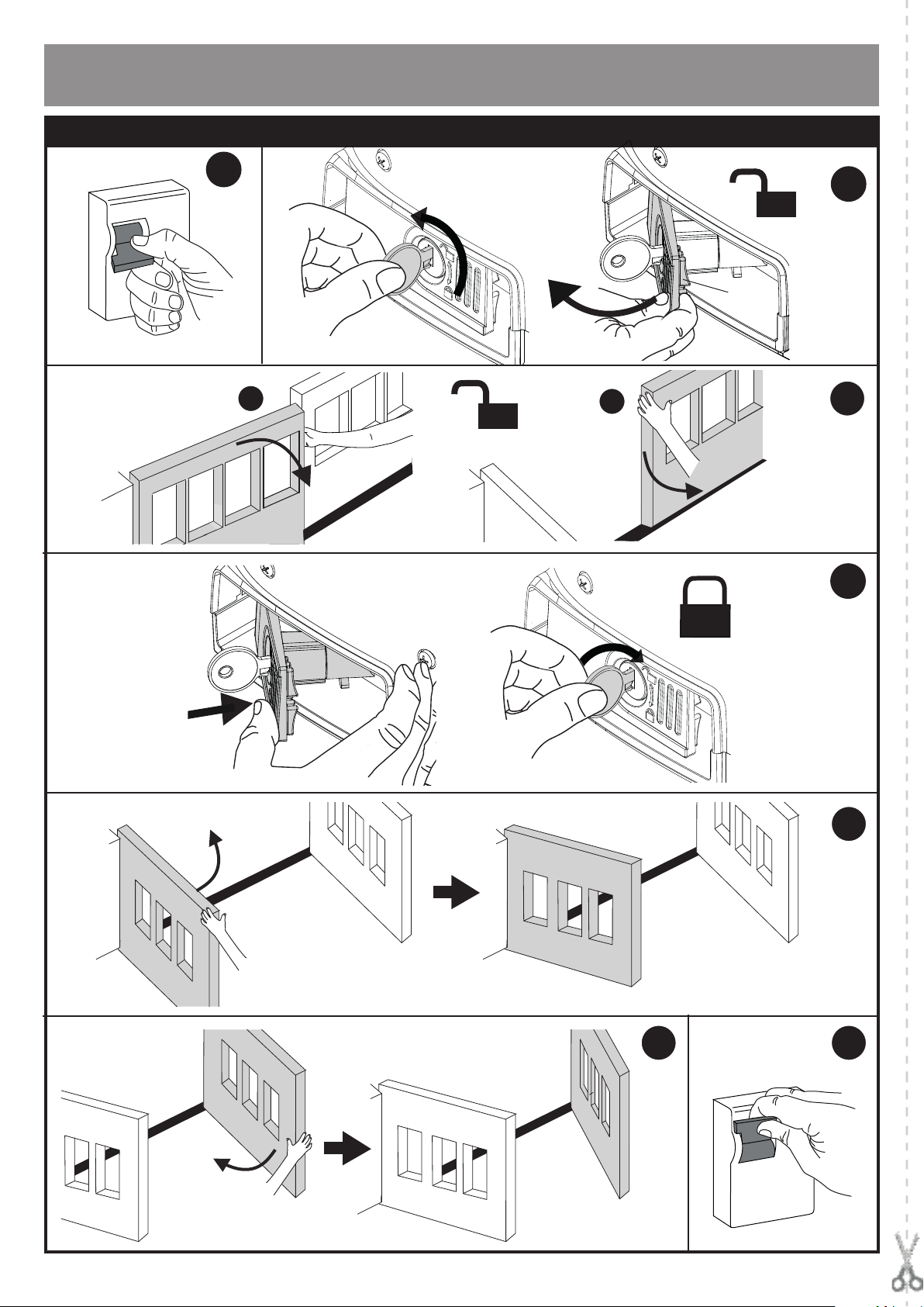
MANUALE D’USO: MANOVRA DI EMERGENZA / USER GUIDE: EMERGENCY OPERATION
MANUEL D’UTILISATION: DE LA MANOEUVRE D’URGENCE / BEDIENUNGSHANDBUCH: NOTFALLMANÖVER
MANUAL DE USO: MANIOBRA DE EMERGENCIA / MANUAL DE USO-MANOBRA DE EMERGÊNCIA
FIG. 1
A
(
1
8
0
°
)
S
D812939 00096_03
B
click
1
2
C
D
(180°)
E
8 - VIRGO SMART BT A
click
E
F
ON

INSTALLER WARNINGS
WARNING! Important safety instructions. Carefully read and comply with
all the warnings and instructions that come with the product as incorrect
installation can cause injury to people and animals and damage to property.
The warnings and instructions give important information regarding safety,
installation, use and maintenance. Keep hold of instructions so that you can
attach them to the technical le and keep them handy for future reference.
GENERAL SAFETY
This product has been designed and built solely for the purpose indicated herein.
Uses other than those indicated herein might cause damage to the product and
create a hazard.
- The units making up the machine and its installation must meet the requirements
of the following European Directives, where applicable: 2014/30/UE, 2014/35/UE,
2006/42/UE, 2011/305/UE, 2014/53/UE and later amendments. For all countries
outside the UE, it is advisable to comply with the standards mentioned, in addition to any national standards in force, to achieve a good level of safety.
- The Manufacturer of this product (hereinafter referred to as the “Firm”) disclaims
all responsibility resulting from improper use or any use other than that for
which the product has been designed, as indicated herein, as well as for failure
to apply Good Practice in the construction of entry systems (doors, gates, etc.)
and for deformation that could occur during use.
- Installation must be carried out by qualied personnel (professional installer,
according to EN 12635), in compliance with Good Practice and current code.
- Before installing the product, make all structural changes required to produce
safety gaps and to provide protection from or isolate all crushing, shearing and
dragging hazard areas and danger zones in general in accordance with the
provisions of standards EN 12604 and 12453 or any local installation standards.
Check that the existing structure meets the necessary strength and stability
requirements.
- Before commencing installation, check the product for damage.
- The Firm is not responsible for failure to apply Good Practice in the construction
and maintenance of the doors, gates, etc. to be motorized, or for deformation
that might occur during use.
- Make sure the stated temperature range is compatible with the site in which the
automated system is due to be installed.
- Do not install this product in an explosive atmosphere: the presence of ammable
fumes or gas constitutes a serious safety hazard.
- Disconnect the electricity supply before performing any work on the system.
Also disconnect buer batteries, if any are connected.
- Before connecting the power supply, make sure the product’s ratings match the
mains ratings and that a suitable residual current circuit breaker and overcurrent
protection device have been installed upline from the electrical system. Have
the automated system’s mains power supply tted with a switch or omnipolar
thermal-magnetic circuit breaker with a contact separation that provide full
disconnection under overvoltage category III conditions.
- Make sure that upline from the mains power supply there is a residual current
circuit breaker that trips at no more than 0.03A as well as any other equipment
required by code.
- Make sure the earth system has been installed correctly: ear th all the metal parts
belonging to the entry system (doors, gates, etc.) and all parts of the system
featuring an earth terminal.
- Installation must be carried out using safety devices and controls that meet
standards EN 12978 and EN 12453.
- Impact forces can be reduced by using deformable edges.
- In the event impact forces exceed the values laid down by the relevant standards,
apply electro-sensitive or pressure-sensitive devices.
- Apply all safety devices (photocells, safety edges, etc.) required to keep the
area free of impact, crushing, dragging and shearing hazards. Bear in mind the
standards and directives in force, Good Practice criteria, intended use, the installation environment, the operating logic of the system and forces generated by
the automated system.
- Apply all signs required by current code to identify hazardous areas (residual
risks). All installations must be visibly identied in compliance with the provisions
of standard EN 13241-1.
- Once installation is complete, apply a nameplate featuring the door/gate’s data.
- This product cannot be installed on leaves incorporating doors (unless the motor
can be activated only when the door is closed).
- If the automated system is installed at a height of less than 2.5 m or is accessible,
the electrical and mechanical parts must be suitably protected.
- For roller shutter automation only
1) The motor’s moving parts must be installed at a height greater than 2.5 m
above the oor or other surface from which they may be reached.
2) The gearmotor must be installed in a segregated and suitably protected space
so that it cannot be reached without the aid of tools.
- Install any xed controls in a position where they will not cause a hazard, away
from moving parts. More specically, hold-to-run controls must be positioned
within direct sight of the part being controlled and, unless they are key operated,
must be installed at a height of at least 1.5 m and in a place where they cannot
be reached by the public.
- Apply at least one warning light (ashing light) in a visible position, and also
attach a Warning sign to the structure.
- Attach a label near the operating device, in a permanent fashion, with information on how to operate the automated system’s manual release.
- Make sure that, during operation, mechanical risks are avoided or relevant
protective measures taken and, more specically, that nothing can be banged,
crushed, caught or cut between the part being operated and surrounding parts.
- Once installation is complete, make sure the motor automation settings are
correct and that the safety and release systems are working properly.
- Only use original spare parts for any maintenance or repair work. The Firm disclaims all responsibility for the correct operation and safety of the automated
system if parts from other manufacturers are used.
- Do not make any modications to the automated system’s components unless
explicitly authorized by the Firm.
- Instruct the system’s user on what residual risks may be encountered, on the
control systems that have been applied and on how to open the system manually in an emergency. give the user guide to the end user.
- Dispose of packaging materials (plastic, cardboard, polystyrene, etc.) in accordance with the provisions of the laws in force. Keep nylon bags and polystyrene
out of reach of children.
WIRING
WARNING! For connection to the mains power supply, use: a multicore cable with
a cross-sectional area of at least 5x1.5mm
phase power supplies or 3x1.5mm2 for single-phase supplies (by way of example,
type H05RN-F cable can be used with a cross-sectional area of 4x1.5mm2). To connect auxiliary equipment, use wires with a cross-sectional area of at least 0.5 mm2.
- Only use pushbuttons with a capacity of 10A-250V or more.
- Wires must be secured with additional fastening near the terminals (for example,
using cable clamps) in order to keep live parts well separated from safety extra
low voltage parts.
- During installation, the power cable must be stripped to allow the earth wire
to be connected to the relevant terminal, while leaving the live wires as short
as possible. The earth wire must be the last to be pulled taut in the event the
cable’s fastening device comes loose.
WARNING! safety extra low voltage wires must be kept physically separate from
low voltage wires.
Only qualied personnel (professional installer) should be allowed to access
live parts.
CHECKING THE AUTOMATED SYSTEM AND MAINTENANCE
Before the automated system is nally put into operation, and during maintenance
work, perform the following checks meticulously:
- Make sure all components are fastened securely.
- Check starting and stopping operations in the case of manual control.
- Check the logic for normal or personalized operation.
- For sliding gates only: check that the rack and pinion mesh correctly with 2 mm
of play along the full length of the rack; keep the track the gate slides on clean
and free of debris at all times.
- For sliding gates and doors only: make sure the gate’s running track is straight
and horizontal and that the wheels are strong enough to take the weight of the
gate.
- For cantilever sliding gates only: make sure there is no dipping or swinging
during operation.
- For swing gates only: make sure the leaves’ axis of rotation is perfectly vertical.
-For barriers only: before opening the door, the spring must be decompressed
(vertical boom).
- Check that all safety devices (photocells, safety edges, etc.) are working properly
and that the anti-crush safety device is set correctly, making sure that the force
of impact measured at the points provided for by standard EN 12445 is lower
than the value laid down by standard EN 12453.
- Impact forces can be reduced by using deformable edges.
- Make sure that the emergency operation works, where this feature is provided.
- Check opening and closing operations with the control devices applied.
- Check that electrical connections and cabling are intact, making extra sure that
insulating sheaths and cable glands are undamaged.
- While performing maintenance, clean the photocells’ optics.
- When the automated system is out of service for any length of time, activate the
emergency release (see “EMERGENCY OPERATION” section) so that the operated
part is made idle, thus allowing the gate to be opened and closed manually.
-
If the power cord is damaged, it must be replaced by the manufacturer or their
technical assistance department or other such qualied person to avoid any risk .
- If “D” type devices are installed (as dened by EN12453), connect in unveried
mode, foresee mandatory maintenance at least every six months
- The maintenance described above must be repeated at least once yearly or at
shorter intervals where site or installation conditions make this necessary.
WARNING!
Remember that the drive is designed to make the gate/door easier to use and
will not solve problems as a result of defective or poorly performed installation
or lack of maintenance
Materials must be disposed of in accordance with the regulations in
DISMANTLING
If the automated system is being dismantled in order to be reassembled at another
site, you are required to:
- Cut o the power and disconnect the whole electrical system.
- Remove the actuator from the base it is mounted on.
- Remove all the installation’s components.
- See to the replacement of any components that cannot be removed or happen
to be damaged.
SCRAPPING
force. Do not throw away your discarded equipment or used batteries
with household waste. You are responsible for taking all your waste
electrical and electronic equipment to a suitable recycling centre.
2
or 4x1.5mm2 when dealing with three-
DECLARATIONS OF CONFORMITY CAN BE FOUND AT http://www.bft-
automation.com/CE
INSTRUCTIONS FOR USE AND ASSEMBLY CAN BE FOUND IN THE DOWNLOAD SECTION.
Anything that is not explicitly provided for in the installation manual is not allowed. The operator’s proper operation can only be
guaranteed if the information given is complied with. The Firm shall
not be answerable for damage caused by failure to comply with the
instructions featured herein.
While we will not alter the product’s essential features, the Firm reserves
the right, at any time, to make those changes deemed opportune to
improve the product from a technical, design or commercial point of
view, and will not be required to update this publication accordingly.
D812939 00096_03
10 - VIRGO SMART BT A
D811766_17

INSTALLAZIONE VELOCE-QUICK INSTALLATION-INSTALLATION RAPIDE
SCHNELLINSTALLATION-INSTALACIÓN RÁPIDA - INSTALAÇÃO RÁPIDA
D812939 00096_03
5x0,75mm
A
2x1,5mm
3x0,75mm
2x0,75mm
ENGLISH FRANÇAIS ESPAÑOL PORTUGUÊSDEUTSCHITALIANO
5x0,75mm
2x0,75mm
P3
188
P2
P1
S
Ø 20
224
B
292
VIRGO SMART BT A - 15

1
A
C
D812939 00096_03
B
700
2
337
125
MIN
12.5
35
123
MIN
300
sx
APERTURA VERSO L’ESTERNO
5
OUTWARDS OPENING
OUVERTURE VERS L’EXTÉRIEUR
ÖFFNUNG NACH AUSSEN
APERTURA HACIA EL EXTERIOR
ABERTURA PARA O EXTERNO
255
128.5
470
90°
60
62
3 4
390
125
MIN
12.5
MAX
235
240
453
35
140
123
123
62
MIN
300
30 90° 92° 95° 100° 102° 105° 107° 110° 112° 115° 118° 120°
40 90° 92° 95° 100° 102° 105° 107° 110° 112° 115° 115° 118°
50 90° 92° 95° 100° 102° 105° 107° 110° 110° 110° 115° 115°
60 90° 92° 95° 100° 102° 105° 107° 107° 110° 110° 115° 115°
70 90° 92° 95° 97° 100° 102° 107° 107° 110° 110° 112° 115°
80 90° 92° 95° 97° 100° 102° 105° 107° 107° 110° 112° 112°
90 90° 92° 95° 97° 100° 102° 105° 107° 107° 110° 112° 112°
100 90° 92° 95° 97° 100° 102° 105° 105° 107° 110° 112° 112°
110 90° 92° 95° 97° 100° 102° 102° 105° 107° 107° 110° 112°
120 90° 92° 95° 97° 100° 100° 102° 105° 107° 107° 110° 112°
130 90° 92° 95° 97° 100° 100° 102° 105° 105° 107° 110°
B
140 90° 92° 92° 97° 97° 100° 102° 105° 105° 107°
150 90° 90° 92° 97° 97° 100° 102° 102° 105°
160 90° 90° 92° 95° 97° 100° 100° 102°
170 90° 90° 92° 95° 97° 100° 100°
180 90° 90° 92° 95° 97° 100°
190 90° 90° 92° 95° 97°
200 90° 90° 92° 95°
210 90° 90° 92° 95°
220 90° 90° 92°
230 90° 90°
235 90°
sx
128,5 140 150 160 170 180 190 200 210 220 230 240 250
MIN
300
A
sx
30
120°
62
16 - VIRGO SMART BT A

1 2
A
D812939 00096_03
B
3
D
Non in dotazione
Not supplied
Ne sont pas fournis
Nicht im lieferum
No asignadas en el
equipamiento base
Não fornecidas
MAX M10
MAX L=25 mm
62
min 300
4
o
or
ou
oder
o
ou
ENGLISH FRANÇAIS ESPAÑOL PORTUGUÊSDEUTSCHITALIANO
25 MAX
D
E
P
Destra - Right
Droitea - Rechts
Derecha - Direita
D
L
Sinistra - Left
Gauche - Links
Izquierda - Esquerda
F
VIRGO SMART BT A - 17
 Loading...