


Bertazzoni MAST366GASXTLP, PROF304GASROTLP, PROF366GASARTLP, PROF486GGASROTLP, MAST304GASXVLP Installation Manual

BERTAZZONI
INSTALLATION MANUAL
FREESTANDING FULL GAS RANGES
3070290
WWW.BERTAZZONI.COM

/ Table of contents
TABLE OF CONTENTS
WARNINGS ___________________________________________________________________ |
4 |
|
DATA RATING LABEL ___________________________________________________________ |
6 |
|
BEFORE INSTALLATION |
________________________________________________________ |
6 |
VENTILATION PREPARATION ____________________________________________________ |
7 |
|
SPECIFICATIONS ______________________________________________________________ |
7 |
|
CLEARENCE DIMENSIONS ______________________________________________________ |
9 |
|
INSTALLATION REQUIREMENTS _________________________________________________ |
10 |
|
Electrical ___________________________________________________________________ |
10 |
|
Gas ________________________________________________________________________ |
10 |
|
ELECTRICAL CONNECTION _____________________________________________________ |
10 |
|
WIRING DIAGRAM _____________________________________________________________ |
11 |
|
GAS CONNECTION _____________________________________________________________ |
12 |
|
Manual shut-o valve |
_________________________________________________________ |
12 |
Flexible connections __________________________________________________________ |
12 |
|
Pressure test-point stopper valve _______________________________________________ |
12 |
|
Pressure regulator ____________________________________________________________ |
13 |
|
INSTALLATION ________________________________________________________________ |
14 |
|
Unpackaging the range |
________________________________________________________ |
14 |
Removing the oven door _______________________________________________________ |
14 |
|
Installing the legs _____________________________________________________________ |
15 |
|
Installing the worktop frontguard ________________________________________________ |
15 |
|
Installing the island trim _______________________________________________________ |
16 |
|
Installing backguard (optional) __________________________________________________ |
16 |
|
INSTALLING THE ANTI-TIP DEVICES ______________________________________________ |
17 |
|
Anti-tip brackets ______________________________________________________________ |
17 |
|
Anti-tilt chain ________________________________________________________________ |
17 |
|
GAS CONVERSION _____________________________________________________________ |
18 |
|
INSTALLATION CHECKLIST ______________________________________________________ |
22 |
|
FINAL PREPARATION ___________________________________________________________ |
22 |
|
BERTAZZONI SERVICE |
_________________________________________________________ |
23 |
2

/ Models
Models |
Models |
MAST304GASXV |
PROF304GASART |
MAST304GASXVLP |
PROF304GASBIT |
MAST305GASBIE |
PROF304GASGIT |
MAST305GASNEE |
PROF304GASNET |
MAST305GASXE |
PROF304GASROT |
MAST305GASXELP |
PROF304GASXT |
MAST365GASBIE |
PROF304GASXTLP |
MAST365GASNEE |
PROF366GASART |
MAST365GASXE |
PROF366GASBIT |
MAST365GASXELP |
PROF366GASGIT |
MAST366GASXT |
PROF366GASNET |
MAST366GASXTLP |
PROF366GASROT |
MAST486GGASBIE |
PROF366GASXT |
MAST486GGASNEE |
PROF366GASXTLP |
MAST486GGASXE |
PROF486GGASART |
MAST486GGASXELP |
PROF486GGASBIT |
MAST486GGASXT |
PROF486GGASGIT |
MAST486GGASXTLP |
PROF486GGASNET |
|
PROF486GGASROT |
|
PROF486GGASXT |
|
PROF486GGASXTLP |
3

/ Warnings
WARNINGS
To ensure proper and safe operation, the appliance must be properly installed and grounded by a qualifi ed technician. DO NOT attempt to adjust, repair, service, or replace any part of your appliance unless it is specifi cally recommended in this manual.All other servicing should be referred to a qualifi ed servicer. Have the installer show you the location of the gas shuto valve and how to shut it o in an emergency. A certifi ed technician is required for any adjustments or conversions to Natural or LP gas.
FOR THE INSTALLER: Before installing the Bertazzoni appliance, please read these instructions carefully. This appliance shall be installed in accordance with the manufacturer’s installation instructions.
IMPORTANT: Leave these instructions with the owner, who should save them for local inspector’s use and for future reference. DO NOT remove permanently a xed labels, warnings, or plates from product. This may void the warranty.
Installation must conform with all local codes. In
•United States: installation must conform with the National Fuel Gas Code ANSI Z223.1 INFPA54
•Massachusetts: All gas products must be installed by a “Massachusetts” licensed plumber or gasfi tter. A “T” type handle manual valve must be installed in the gas supply line to the appliance.
•Canada: Installation must be in accordance
with the current CAN/CGA B149.1 & 2 Gas Installation codes and/or local codes. Electri-the absence of codes:
cal installation must be in accordance with the current CSA C22.1 Canadian Electrical Codes Part 1 and/or local codes.
This range is NOT designed for installation in manufactured (mobile) homes or recreational park trailers.
DO NOT install this range outdoors.
This appliance must be properly grounded. Grounding reduces the risk of electric shock by providing a safe pathway for electric current in the event of a short circuit.
Warning!
To avoid risk of property damage, personal injury or death; follow information in this manual exactly to prevent a fi re or explosion.
WARNING!
If the information in these instructions is not followed exactly, a fire or explosion may result causing property damage, personal injury or death.
-Do not store or use gasoline or other fl ammable vapors and liquid in the vicinity of this or any other appliance.
-WHAT TO DO IF YOU SMELL GAS
•Do not try to light any appliance. •Do not touch any electrical switch.
•Do not use any phone in your building. •Immediately call your gas supplier from a neghbor’s phone. Follow the gas supplier’s instructions.
•If you cannot reach your gas suppliers, call the fire department.
- Installation and service must be performed by a qualifi ed installer, service agency or the gas supplier
DANGER!!! ELECTRIC SHOCK HAZARD!!!
To avoid risk of electrical shock, personal injury or death, verify that the appliance has been properly grounded in accordance with local codes or in absence of codes, with the National Electrical Code (NEC). ANSI/NFPA 70latest edition.
DANGER!!! GAS LEAK HAZARD!!!
To avoid risk of personal injury or death, leak-te- sting of the appliance must be conducted according to the manufacturer’s instructions. Before placing appliance in operation, always check for gas leaks with water and soap solution.
DO NOT USE AN OPEN FLAME TO CHECK FOR GAS LEAKS.
Warning - tipping hazard
A child or adult can tip over the range and be killed.
Install the anti-tip device to the structure and/or the range. Verify the anti-tip device has been properly installed and engaged.
4

/ Warnings
Engage the range to the anti-tip device by anti-tip brackets or anti-tip chain (see installing the an- ti-tip device chapter). Ensure the anti-tip device is re-engaged when the range is moved. Re-engage the anti-tip device if the range is moved. Do not operate the range without te anti-ti- pdevice in place and engaged.
See anti-tip device installation instructions for details.
Failure to do so can result in death or serious burns to children or adults.
DO NOT lift the range by the oven door’s handle, as this may damage the door hinges and cause the door to fi t incorrectly.
DO NOT lift the appliance by the range’s control panel.
The unit is heavy and should be handled accordingly. Proper safety equipment such as gloves and adequate manpower of at least two people must be used in moving the range to avoid injury and to avoid damage to the unit or the fl oor.
Rings, watches, and any other loose items that may damage the unit or otherwise might become entangled with the unit should be removed.
Hidden surfaces may have sharp edges. Use caution when reaching behind or under appliance. DO NOT use a hand truck or appliance dolly on the back or front of the unit. Handle from the side only.
 WARNING:
Cancer and Reproductiv Harm-
www.P65Warnings.ca.gov.
5

/ Data rating label / Before installation
DATA RATING LABEL
The data rating label shows the model and serial number of the range. It is located under the control panel and in the last page of this manual.
BEFORE INSTALLATION
•This appliance shall only be installed by an authorized professional.
•This appliance shall be installed in accordance with the manufacturer’s installation instructions.
•This appliance must be installed in accordance with the norms & standards of the country where it will be installed.
•The installation of this appliance must conform to local codes and ordinances. In the absence of local codes, Installations must conforms to American National Standards, National Fuel Gas Code ANSI Z223.1 – latest edition/NFPA 54 or B149.1.
•The appliance, when installed, must be electrically grounded in accordance with local codes or, in the absence of local codes, with the National Electrical Code, ANSI/NFPA 70.
If local codes permit, a fl exible metal appliance connection conduit with the newAGAor CGAcertifi ed design, max. 5 feet (1,5 m) long, ½” I.D. is recommended for connecting this appliance to the gas supply line. Do not bend or damage the fl exible connector when moving the appliance.
This appliance must be used with the pressure regulator provided.
The regulator shall be properly installed in order to be accessible when the appliance is installed in its
final location. The pressure regulator must be set for the type of gas to be used. The pressure regulator has ½” female pipe thread. The appropriate
fitting must be determined based on the size of your gas supply line, the fl exible metal connector and the shuto valve.
The appliance must be isolated from the gas supply piping system by closing its individual manual shuto valve during any pressure testing of the gas supply piping system at test pressures equal to or less than 1/2 PSI (13,8” w.c. or 3,5 kPa).
All opening and holes in the wall and fl oor, back and under the appliance shall be sealed before installation of the appliance.
A manual valve shall be installed in an accessible location in the gas line external to the appliance for the purpose of turning on or shutting o gas to the appliance.
Type of gas
This range can be used with Natural or LP/Propane gas. The range is shipped from the factory for use with the gas indicated on the rating label positioned on the lower face of the control panel and in the last page of this manual.Astep by step conversion procedure is also included in this manual and in each conversion kit.
Gas pressure
The maximum inlet gas supply pressure incoming to the gas appliance pressure regulator is 1/2 PSI (13,8’’ iwc or 3,5 kPa). The minimum gas supply pressure for checking the regulator setting shall be at least 1“ iwc (249 Pa) above the inlet specifi ed manifold pressure to the appliance; this operating pressure is 4” iwc (1.00 kPa) for Natural Gas and 10” iwc (2.50 kPa) for LP Gas.
Room ventilation
An exhaust fan may be used with the appliance; in each case it shall be installed in conformity with the appropriate national and local standards. Exhaust hood operation may a ect other vented appliances; in each case it shall be installed in conformity with the appropriate national and local standards.
Warning
This appliance should not be installed with a ventilation system that directs air in a downward direction toward the range. This type of ventilation system may cause ignition and combustion problems with the appliance resulting in personal injury, property damage, or unintended operation. Ventilating systems that direct the air upwards do not have any restriction.
Do not use aerosol sprays in the vicinity of this appliance while it is in operation.
6
/ Ventilation preparation / Specifi cations
VENTILATION PREPARATION
This range will best perform when installed with Bertazzoni exhaust hoods. These hoods have been designed to work in conjunction with the Bertazzoni range and have the same fi nish for a perfect look.
Before installation of the exhaust hood, consult local or regional building and installation codes for additional specifi c clearance requirements.
Refer to the range hood installation instructions provided by the manufacturer for additional information.
Select Hood and Blower Models:
•For wall installations, the hood should be equal or larger width than the range. Where space permits, a hood larger than the range may be desirable for improved ventilation performance.
•For island installations, the hood width should overhang the range by a minimum of 3” (76 mm) on each side.
Hood Placement:
•For best removal of smoke and odors, the lower edge of the hood should be installed between 25 1/2” (65 cm) and 31 1/2” (80 cm) above the range cooking surface.
•If the hood contains any combustible materials (i.e. a wood covering), it must be installed at a minimum of 36” (914 mm) above the cooking surface.
Consider Make-Up Air:
Due to the high volume of ventilation air, a source of outside replacement air is recommended. This is particularly important for tightly sealed and insulated homes. A qualifi ed heating and ventilating contractor should be consulted.
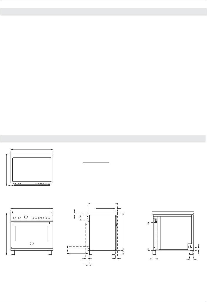
SPECIFICATIONS
A
|
30’’ |
A |
48’’ |
/8 |
36’’ |
||
27'' |
|
|
|
|
|
25'' /16 |
|
A |
|
1'' 15/16 |
|
1''5/8 |
5'' |
|
|
MAX |
|
|
32'' |
37'' 1/2 |
|
|
|
|
'' / |
|
- 5'' 1/2 |
|
|
3'' 3/4 |
|
|
2'' |
1'' 5/8 |
|
|
1'' 1/8 |
|
|
23'' 7/8
|
2'' 7/16 |
3'' 7/16 |
3 '' 11/16 |
7
 Loading...