

Page 1
Instruction Manual
Page 2

Page 3

Table of Contents
NAMES OF PARTS 6
Names of Parts 6
Standard Accessories 7
Extension table 7
Sewing Table and Accessory box 8
Stitch overview 8
GETTING READY TO SEW 9
Connecting the Power Supply 9
Controlling Sewing Speed 10
Machine Operating Buttons 11
Attaching and removing the presser foot holder 13
Dropping or Raising the Feed Dog 14
Changing the needle 14
Fabric and Needle Chart 14
Bobbin Winding and Inserting 15
Threading the Machine 18
Needle threader 19
Drawing up the Bobbin Thread 20
LCD display 21
Setting Mode 22
Adjusting the Thread Tension for a Straight Stitch 23
Adjusting the Needle Thread Tension for a Zigzag Stitch 24
BASIC SEWING 25
Straight Stitch sewing 25
Straight stitch 27
Securing stitch 27
Locking Stitch 27
Stretch Stitch 27
Triple straight stitch 28
Sculpture Stitch 28
Saddle Stitch 28
Zigzag 29
3-step zigzag 30
Stretch Overlock 30
Overlock Stitches 30
Various Kinds of Buttonholes and Their Uses 31
Standard Buttenhole 32
Adjusting the Stitch Width and Density for Buttonholes 34
Round-End Buttonhole 35
Keyhole Buttonhole 35
Stretch Buttonhole 35
Buttonhole with cord 36
Darning program 37
Bartack 38
Eyelet 38
Zipper Sewing 39
Blindstitch 41
Button Sewing 42
Attaching Elastic 43
DECORATIVE STITCHING 43
Vari-Overlock (Scallop seam) 43
Appliqué 44
Scallop Stitch 44
Smocking 45
Patchwork Piecing 46
Fagoting 46
Quilt Stitch 47
Satin Stitches 47
Fringing 48
Drawn work 48
Cross stitch 49
Decorative Stitches 49
Decorative Stitch Combinations 50
Balance 50
CARE OF YOUR MACHINE 51
Cleaning the Hook Race and Feed Dog 51
Installing the Bobbin Holder 51
Problems and Warning Signs 52
Troubleshooting 53
Stitch pattern 54
Overview 54
3
Page 4

IMPORTANT
When using an electrical machine, basic safety
precautions should always be followed, including
the following:
Please read the instruction manual carefully
before using this machine.
Keep the instruction manual at a suitable place
with the machine and hand it over if you give the
machine to a third party.
When the machine is not in use or left unattended, always disconnect the machine from
the power supply system. Unplug it from the
outlet.
WARNING!
To reduce the risk of burns, fire, electric shock or
injury to persons:
DANGER!
To reduce the risk of electric shock:
1. Never leave the machine unattended when
it is plugged in.
2. Always unplug this machine from the electric outlet immediately after using and
before cleaning.
3. LED RADIATION: Do not look directly at
the LED using an optical instrument.
1. The machine mustn’t be used by children
under 8 or by people with reduced physical,
sensory or mental capabilities or if there is a
lack of experience and knowledge how to
operate the machine. Unless they have been
given instruction concerning the use of the
machine and the involved risks by a person
who is responsible for their safety.
2. Do not use this machine as a toy. Close
attention is necessary when this machine is
used by children, near children or people
with reduced sensation.
3. Use this machine only for its intended use
as described in this manual. Use only accessories recommended by the manufacturer.
4. Children should be supervised to ensure
that they do not play with the machine.
5. Never operate this machine if it has a damaged cord or plug, if it is not working properly, if it has been dropped or damaged, or
dropped into water. Return the machine to
the nearest authorized dealer or service
centre for examination, repair, electrical or
mechanical adjustment.
6. Never operate the machine with any air
openings blocked. Keep ventilation openings
of the machine and the foot control free from
accumulation of lint, dust, and loose cloth.
7. Keep fingers away from all moving parts.
Special care is required around the
machine needle.
8. Always use the proper stitch plate. Using
the wrong stitch plate can result in needle
breakage.
9. Do not use bent needles.
10. Do not pull or push the fabric while sewing.
This can result in needle breakage.
11. Switch the machine off (“O”) when making
any adjustments in the needle area, such
as threading or changing the needle,
threading the bobbin, or changing the
presser foot, and the like.
12. Always unplug the machine when performing cleaning or maintenance worksuch as
replacing the sewing light or when making
any other user maintenance adjustments
mentioned in the instruction manual (disconnect the power plug). Cleaning and
maintenance work must not be carried out
by children without supervision.
13. Never drop or insert any object into any
openings.
14. Use this machine only in dry and protected
areas. Never operate the machine in a
damp or wet environment.
15. Do not operate the machine where aerosol
spray products are being used or where
oxygen is being administered.
16. To disconnect, turn the power switch to
(“O”)(off), then remove the plug from the
outlet. Do not unplug by pulling the cord,
instead grasp the plug to pull it from the
outlet.
17. If the supply cord of the foot control is
damaged, it must be replaced by the manufacturer or an appropriate service agent or
a similar qualified person in order to avoid
endangerment.
18. Never place anything on the foot control.
19. The machine may only be used in combination with a foot control of the type YC485-EC-1 (100-240 V area).
4
Page 5
SERVICING OF DOUBLE-
20. The sound pressure level during normal
operation is lower than 75dB(A).
21. This machine is provided with double insulation (except U.S.A/Canada). Use only
identical replacement parts. See instructions for Servicing of double-insulated
products.
INSULATED PRODUCTS
In a double-insulated product, two systems of
insulation are provided instead of grounding. No
grounding means is provided on a double-insulated product nor should a means for grounding
be added to the product. Servicing a doubleinsulated product requires extreme care and
knowledge of the system and should only be
done by qualified service personnel. Replacement parts for a double-insulated product must
be identical to those parts in the product. A
double insulated product is marked with the
words «DOUBLE INSULATION» or «DOUBLE
INSULATED».
The symbol may also be marked on the
product.
SAVE THESE INSTRUCTIONS!
WARNING:
This machine is intended for household use only. If used
intensively or commercially, regular cleaning and especially attentive care is required.
Signs of wear and tear owing to intensive or commercial
use are not covered automatically, even if they occur within
the warranty period. The decision on how to deal with any
such cases rests with the local authorised servicing staff.
PLEASE NOTE:
If the machine is stored in a cold room, it should be brought
to a warm room about one hour before use.
Please note that on disposal, this product must be
safely recycled in accordance with relevant National
legislation relating to electrical /electronic products. If in
doubt please contact your retailer for guidance. (European Union only)
All rights reserved
For technical and product improvement reasons, the machine‘s
features, parts and accessory are subject to unannounced
changes and alterations at any time. The accessory included can
differ from country to country.
EUROPE ONLY:
This appliance may only be used by children over eight
and by persons with reduced physical, sensory or mental
capabilities or by persons who lack experience and knowledge of how to operate the machine under supervision,
after instruction on how to use the equipment safely and
once they have understood the potential dangers. Children
shall not play with the appliance. Cleaning and user maintenance shall not be made by children without supervision.
OUTSIDE OF EUROPE (EXCEPT FOR THE USA
AND CANADA):
This appliance may only be used by persons (including
children) with reduced physical, sensory or mental capabilities or by persons who lack experience and knowledge
of how to operate the machine under supervision and after
instruction on how to use the equipment safely by a person
responsible for their safety.
Children should be supervised to ensure that they do not
play with the appliance.
5
Page 6
NAMES OF PARTS
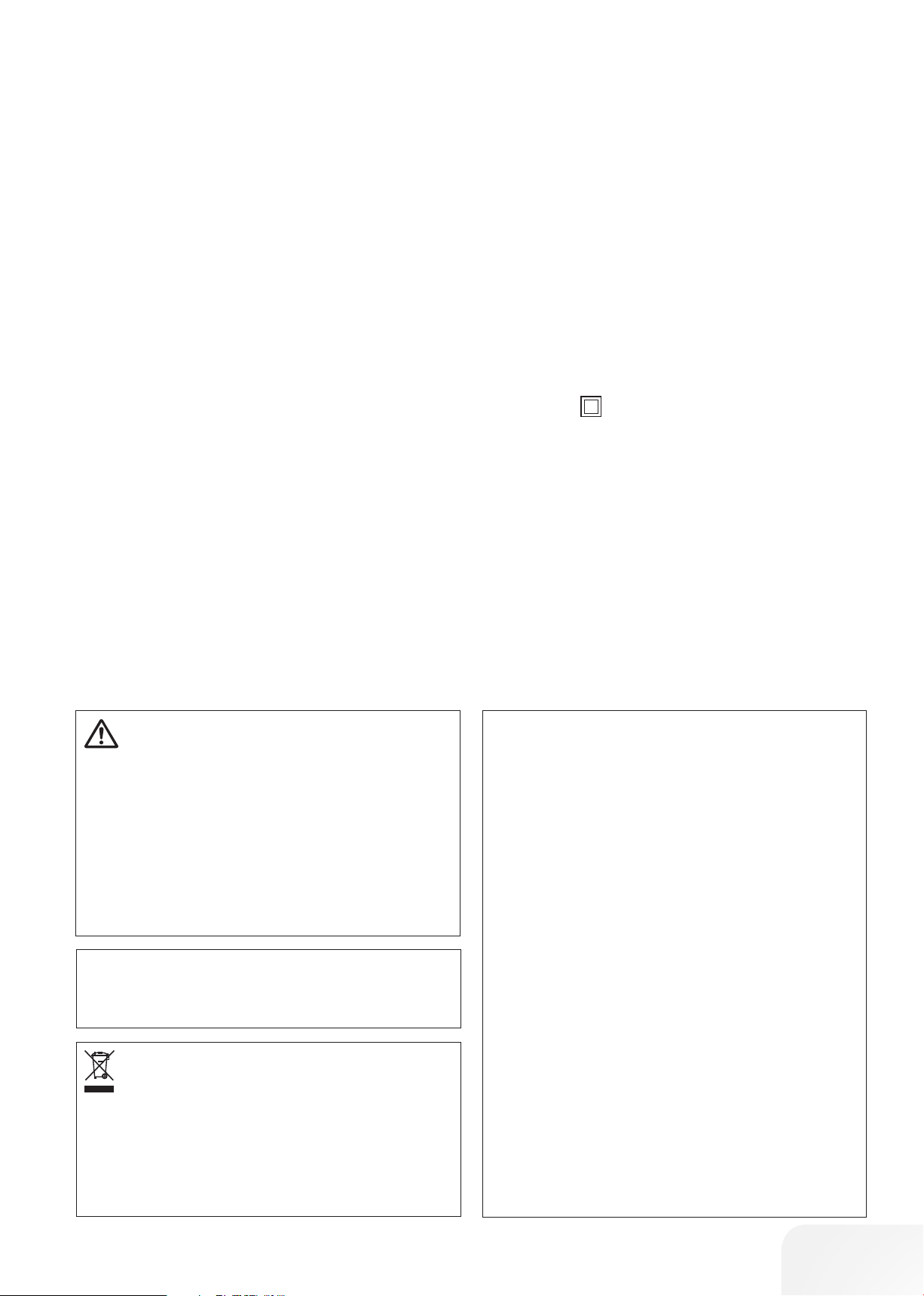
Names of Parts
Sewing table (accessory box)
Stitch plate
Needle Threader
Thread cutter
Head cover
Thread take-up lever
Thread tension
Spool pin
Spool disc large
Bobbin winder spindle
Bobbin winder stopper
Hole for second spool pin
Value set buttons
Cursor buttons
LCD display
Slide speed control
Needle stop up/down button
Auto-lock button
Reverse sewing button
Start/stop button
Drawer for stitch overview
Bobbin cover
Presser foot (Zigzag foot)
Presser foot holder
Needle clamp screw
Needle
Bobbin cover release button
Power cable connection
Foot control connector
Power switch
Handwheel
Carrying handle
Thread guide
Presser Foot Lever
Buttonhole lever
Free arm
Feed dog lever
Foot control
Power cable*
Balance
PLEASE NOTE:
To carry the sewing machine, hold the carrying handle with
your hand, and support the sewing machine with the other
hand.
Design and specifications are subject to change without
prior notice.
*The power cable included may differ from the illustration.
6
Page 7
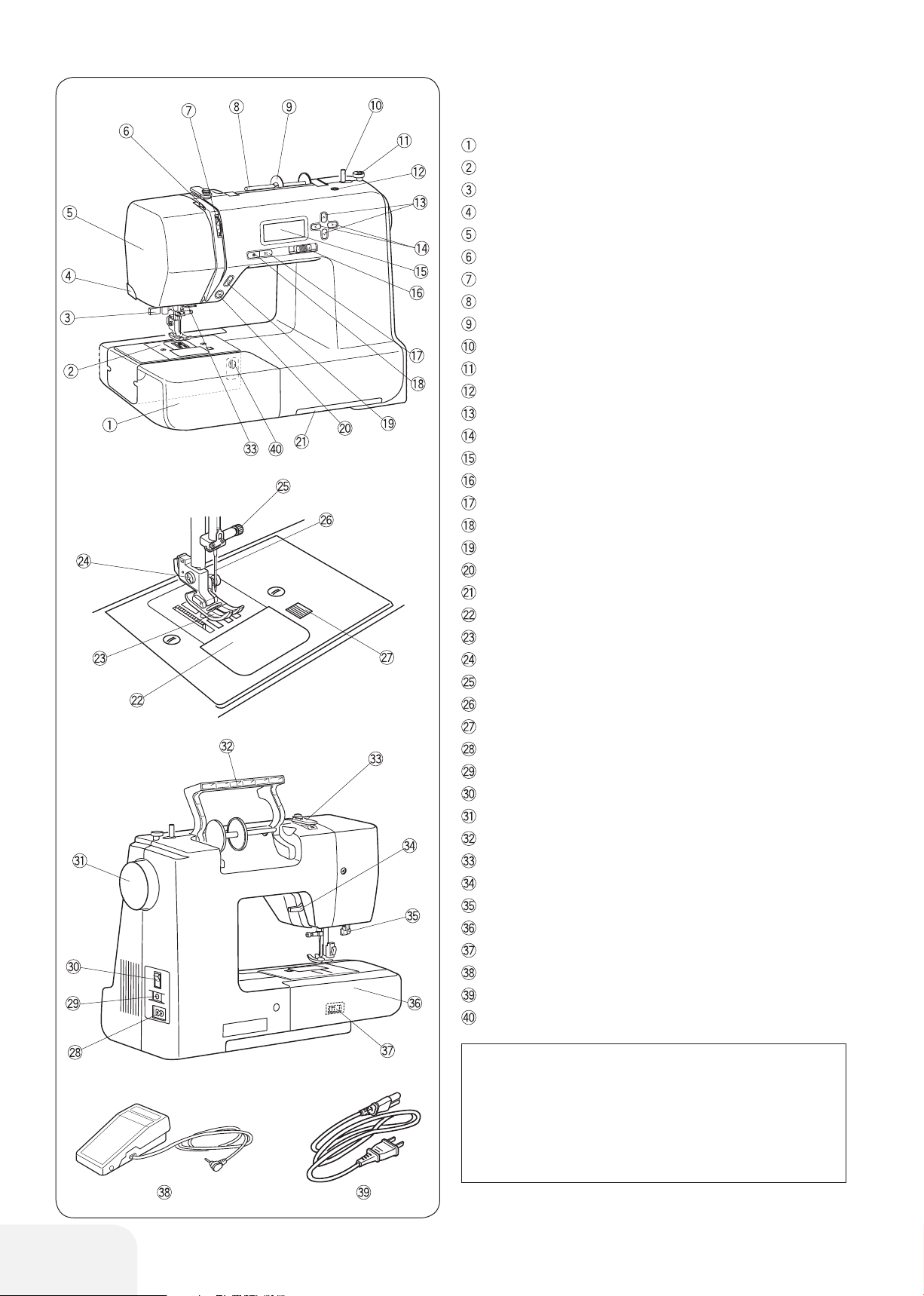
Standard Accessories
Zigzag foot A (set on the machine)
Satin stitch foot F
Buttonhole foot with slide R
Zipper foot E
Button sew-on foot T
Bobbin (x4) (1 set on the machine)
Spool pin felt
Needle set
Second spool pin
Seam ripper (buttonhole opener)
T screwdriver
Brush
Spool disc (Small) (x1) (set on the machine)
Spool disc (Large) (x1)
Spool net
Dust Cover
More information on optional accessories can be found on our
website:
http://www.mybernette.com/accessories
• Dust Cover
Sewing instructions for your own personalized dust
cover are available at:
www.mybernette.com/cover
Extension table
• Attaching the table
Pull the table away from the machine.
Spread the legs of extension table*.
Holding the table with both hands and slide it gently to the right.
Adjusting the table height
Turn setscrews of the table legs with a screwdriver (optional).
* special accessory
7
Page 8
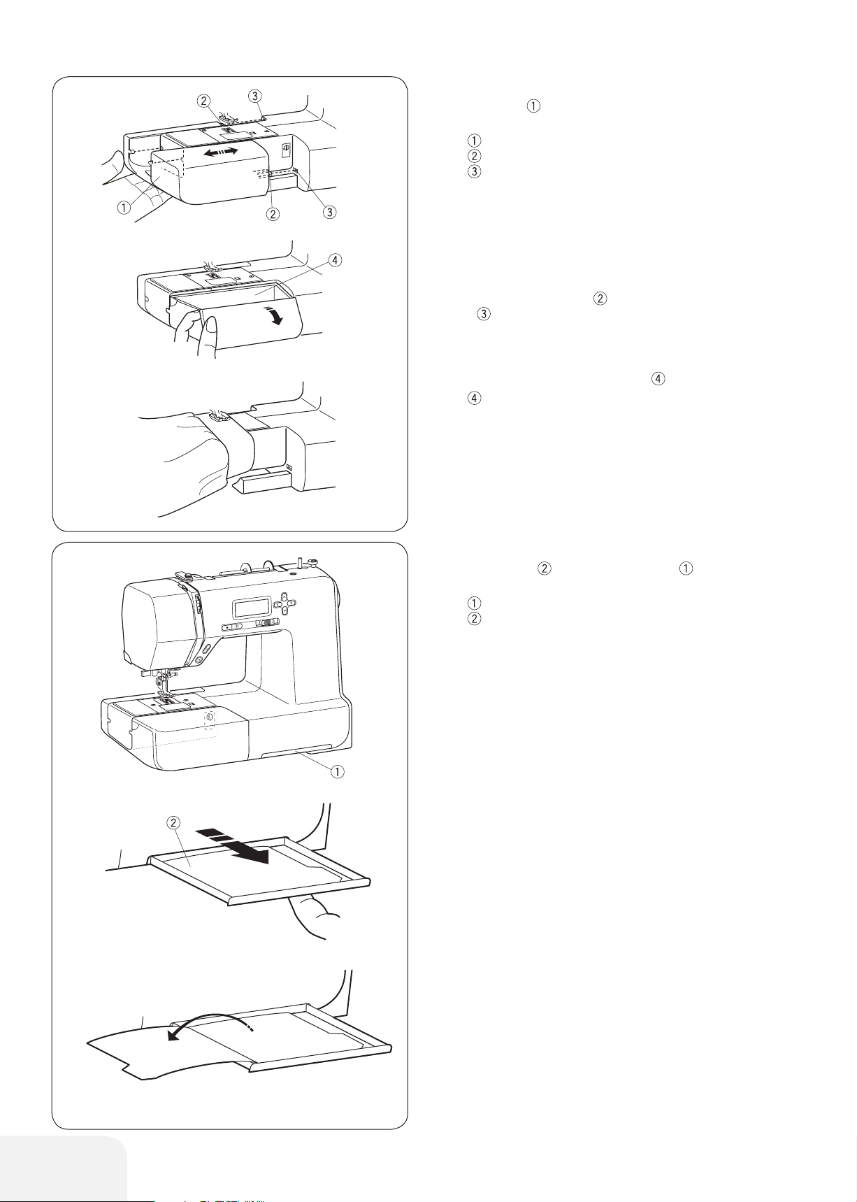
Sewing Table and Accessory box
The sewing table provides an extended sewing area and can
be easily removed for free arm sewing.
Sewing table
Pin
Hole
• Removing Sewing Table
Pull the table away from the machine, as illustrated.
• Attaching Sewing Table
Push the sewing table, inserting the pin into the hole until the
table snaps into the machine. Insert the second spool pin into
the hole .
• Accessory box
The accessories are stored inside the sewing table. Pull the lid
towards you to open the accessory box .
Accessory box
• Free-arm sewing
Free-arm sewing is useful for darning socks and mending the
knee or cuff areas of children’s clothes.
Stitch overview
The stitch overview is stored in the drawer in the lower part
of the sewing machine.
Drawer for stitch overview
Stitch overview
Pull the drawer out with your finger as far as it will go.Turn pages
to refer the stitch overview.
8
Page 9
GETTING READY TO SEW
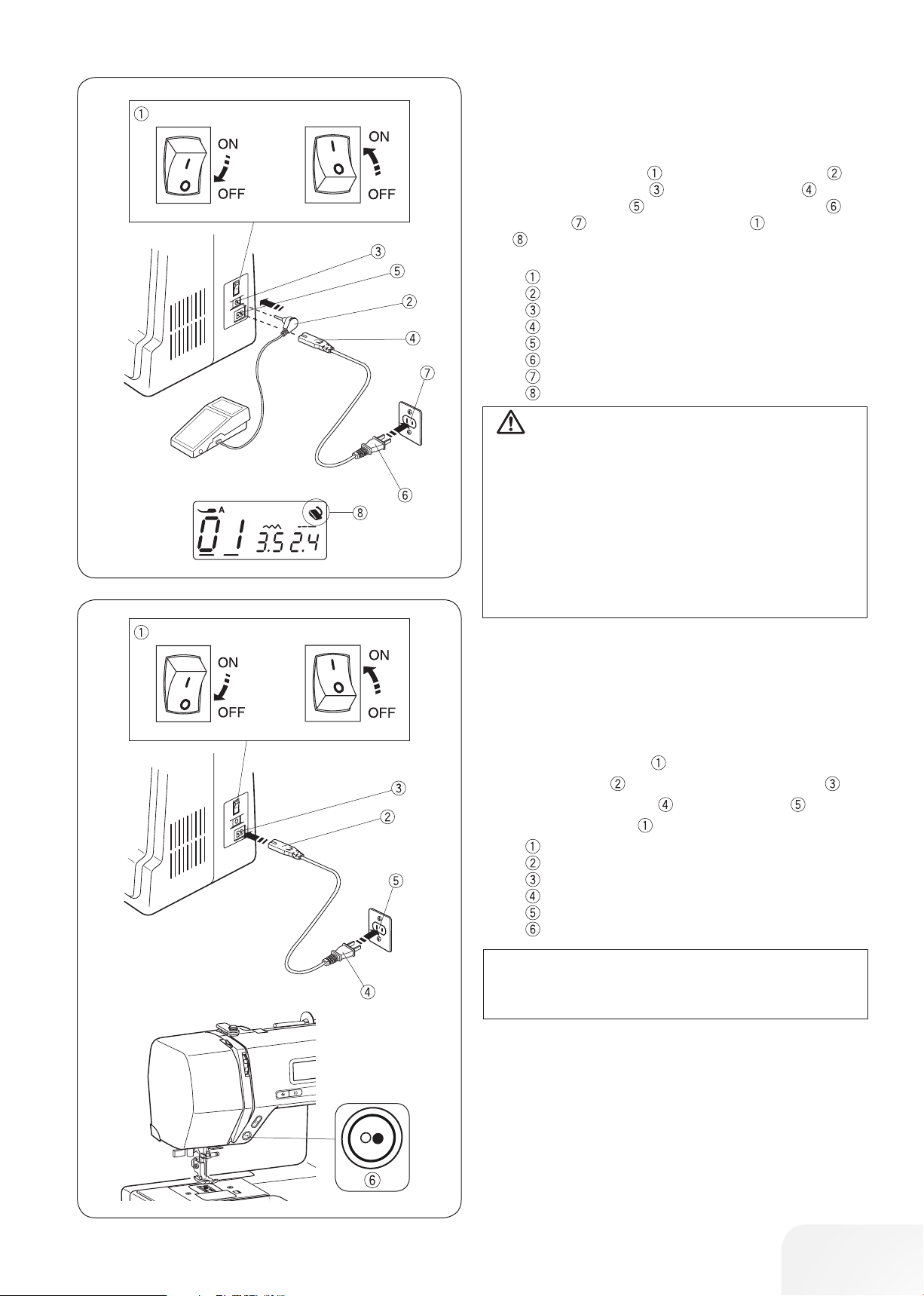
Connecting the Power Supply
• Using the foot control
Switch off the power switch . Insert the foot control plug into
the foot control connection . Insert the cable plug into the
power cable connection . Insert the power supply plug into
the wall outlet . Turn on the power switch . The foot control
sign will be displayed when the foot control is connected to
the machine.
Power switch
Foot control plug
Foot control jack
Cable plug
Power cable connection
Power supply plug
Wall outlet
Foot control sign
WARNING:
While in operation, always keep your eyes on the sewing
area, and do not touch any moving parts such as the
thread take-up lever, handwheel or needle.
Always turn off the power switch and unplug from the
power supply:
- when leaving the machine unattended.
- when attaching or removing parts.
- when cleaning the machine.
Never place anything on the foot control.
• Before Using Your Sewing Machine
Before using your sewing machine for the first time, place a scrap
of fabric under the presser foot and run the machine without
thread for a few minutes. Wipe away any oil which may appear.
• Using the start/stop button
Switch off the power switch .
Insert the cable plug into the power cable connection .
Insert the power supply plug into the wall outlet .
Turn on the power switch .
Power switch
Cable plug
Power cable connection
Power supply plug
Wall outlet
Start/stop button
PLEASE NOTE:
The start/stop button does not work when the foot control
is connected.
• Operating Instructions:
The symbol “0” on a switch indicates the “off” position of a switch.
For appliances with a polarized plug (one blade wider than the
other): To reduce the risk of electric shock, this plug is intended
to fit in a polarized outlet only one way.
If it still does not fit, contact a qualified electrician to install the
proper outlet. Do not modify the plug in any way (U.S.A. and
Canada only).
* Foot control model YC-485EC-1 is used with this sewing
machine.
9
Page 10
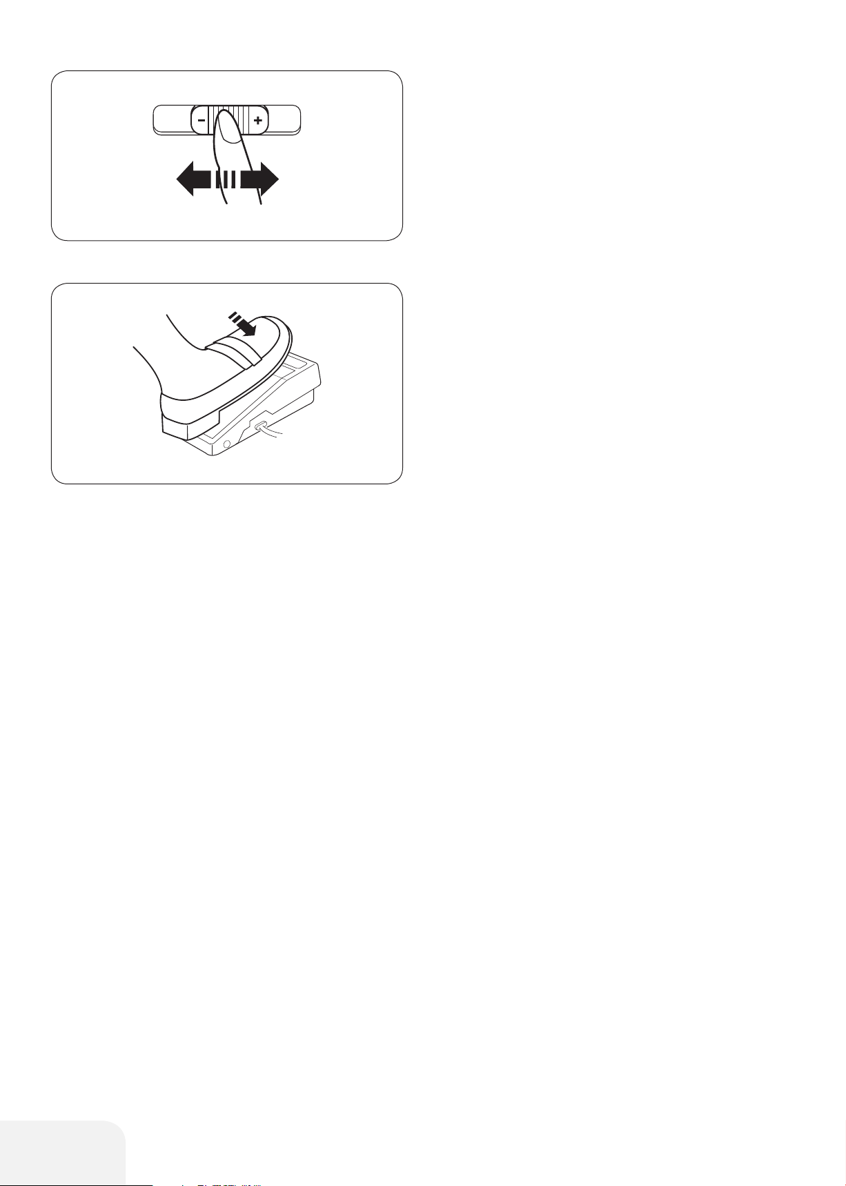
Controlling Sewing Speed
• Slide speed control
Sewing speed can be varied by the slide speed control according
to your sewing needs.
To increase sewing speed, slide the slider to the right.
To decrease sewing speed, slide the slider to the left.
• Foot control
Depress the foot control to start the machine.
The further down you press on the foot control, the faster the
machine runs.
The maximum sewing speed can be varied by the slide speed
control.
10
Page 11
7
1 2 5 6
1 2 5 6
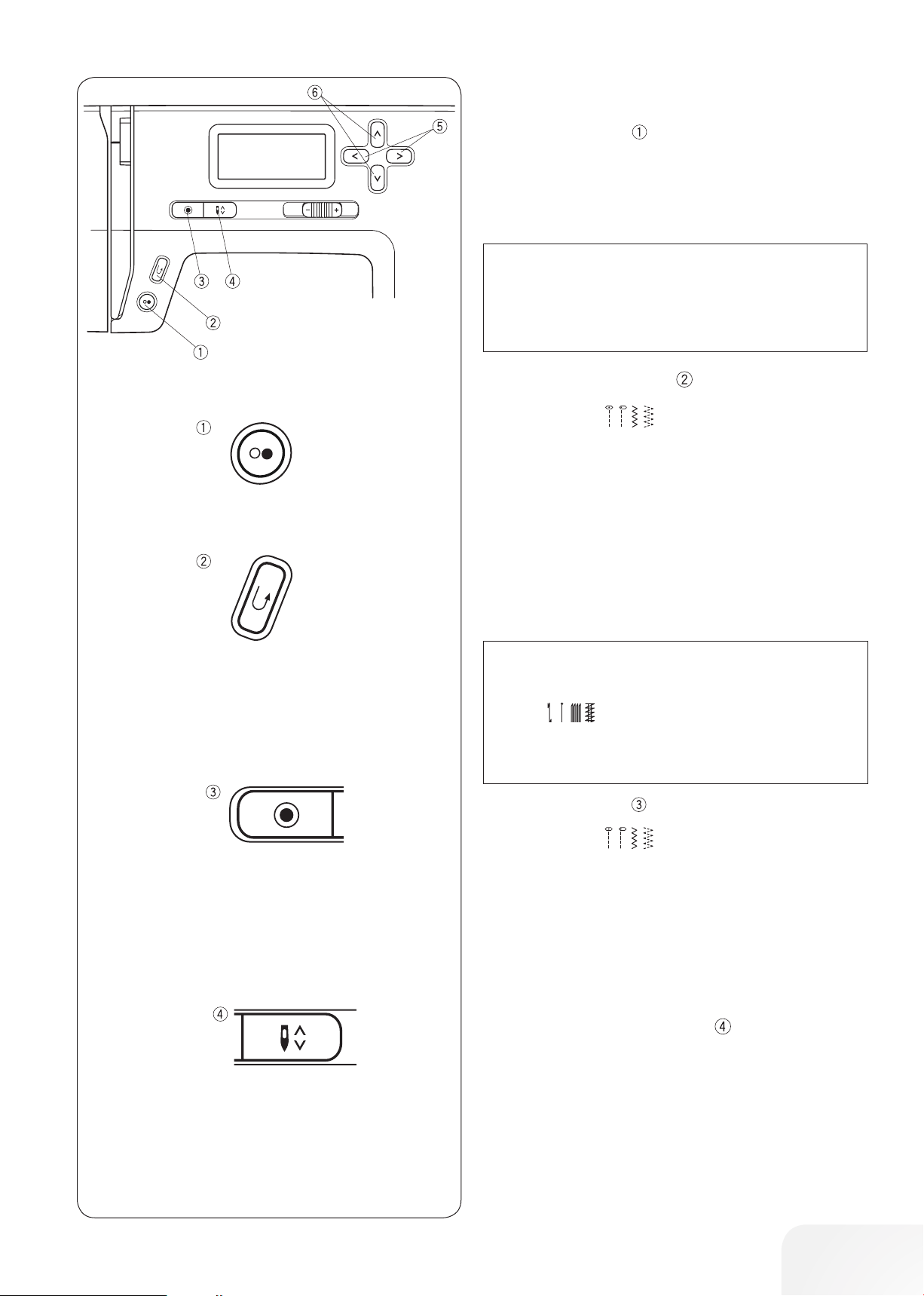
Machine Operating Buttons
• Start/stop button
Press this button to start or stop the machine.
The machine will sew the left row first. The machine starts running slowly for the first few stitches, and it then runs at the speed
set by the slide speed control.
PLEASE NOTE:
The machine runs slowly as long as this button is being
pressed.
The start/stop button cannot be used when the foot control
is connected to the machine.
• Reverse sewing button
When stitch pattern
(01, 02, 05, 06) is selected;
The machine will sew in reverse as long as the reverse sewing
button is pressed. Release the button to sew forward.
When the machine is stopped and foot control is disconnected,
the machine will sew in reverse slowly as long as the reverse
sewing button is pressed. Release the button to stop the
machine.
When any other stitches are selected
If you press the reverse sewing button when sewing any other
patterns, the machine will immediately sew locking stitches and
automatically stop.
PLEASE NOTE:
There will be particular functions of the reverse sewing
button
Refer to page 26, 36 and 37 for instructions.
14
21 22
when pattern is selected.
• Auto-lock button
When stitch pattern
Press the auto-lock button to sew a locking stitch immediately.
The machine will automatically stop.
(01, 02, 05, 06) is selected;
When any other stitches are selected
Press the auto-lock button to sew a locking stitch at the end of
current pattern. The machine will automatically stop.
• Needle stop up/down button
Press the needle stop up/down Button to bring the needle up or
down.
In the case of sewing stop, the needle hold in the desired position until the Needle stop up/down button is pressed again.
11
Page 12
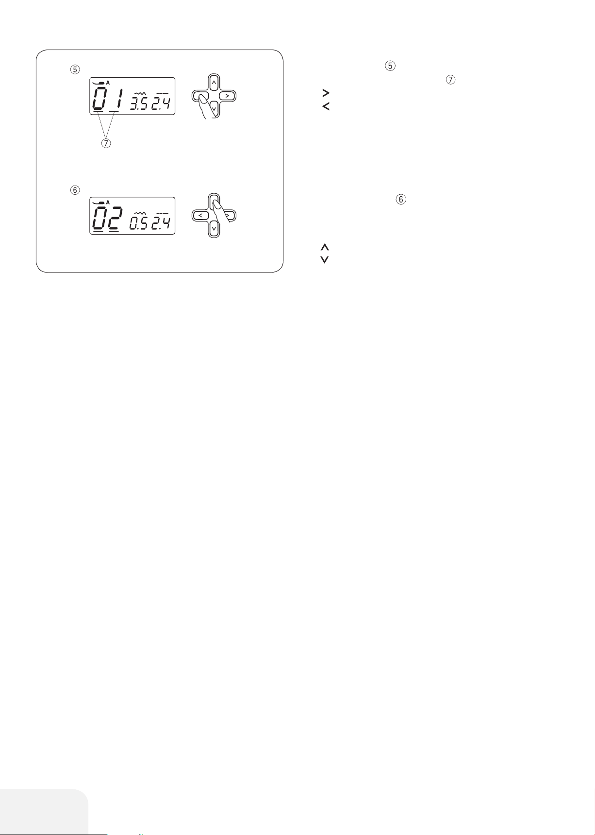
• Cursor buttons
Use these buttons to move the cursor .
Press button to move the cursor to right.
Press button to move the cursor to left.
• Value set buttons
Use these buttons to change the set value.
Move the cursor under the digit you would like to change.
Press button to increase the value.
Press button to decrease the value.
12
Page 13
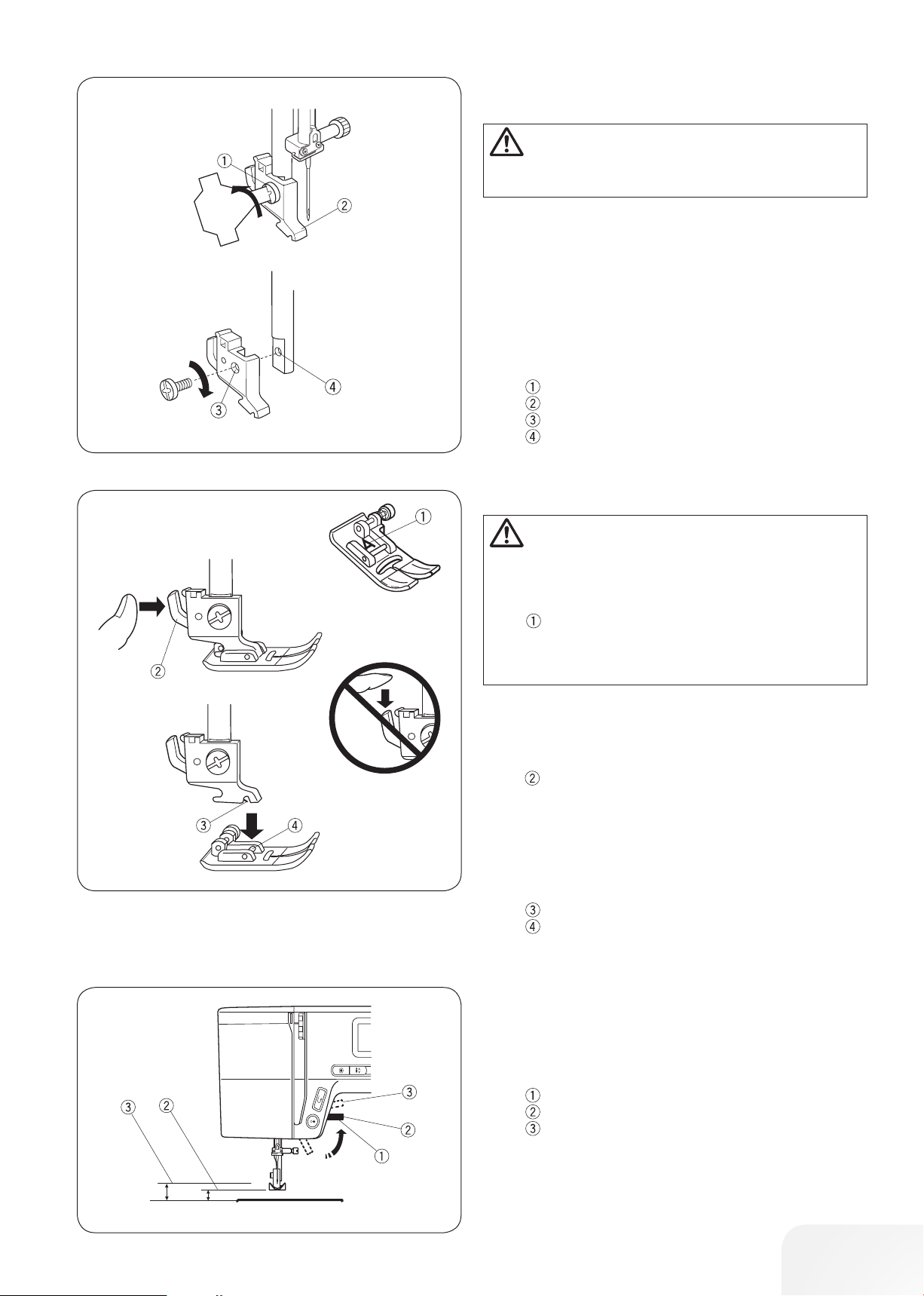
Attaching and removing the presser foot
holder
CAUTION:
Turn OFF the power switch before removing or attaching
the presser foot holder.
Removing Presser foot holder
Remove the setscrew by turning it counterclockwise with a
screwdriver.
Attaching Presser foot holder
Match the hole in the presser foot holder with the threaded hole
in the presser bar.
Fit the setscrew into the hole.
Tighten the setscrew by turning it clockwise with the screwdriver.
Setscrew
Presser foot holder
Hole
Threaded hole
Changing the Presser Foot
CAUTION:
Turn OFF the power switch before changing the foot.
Always use the proper foot for the selected pattern.
The wrong foot can cause the needle to break. Each foot
is marked with an identification letter.
Identification letter
Removing the presser foot
Raise the needle to its highest position by turning the handwheel
counterclockwise. Raise the presser foot, and press the lever on
the back of the presser foot holder.
Lever
Attaching the presser foot
Place the desired presser foot, so that the pin on the foot lies just
under the groove on the presser foot holder.
Lower the presser foot lever to lock the foot in place.
Groove
Pin
Presser Foot Lever
The presser foot lever raises and lowers the presser foot.
You can raise the foot about 1/4˝ (0.6 cm) higher than the normal
up position for easy removal of the presser foot, or to help you
place thick material under the foot.
Presser Foot Lever
Normal up position
Highest position
13
Page 14
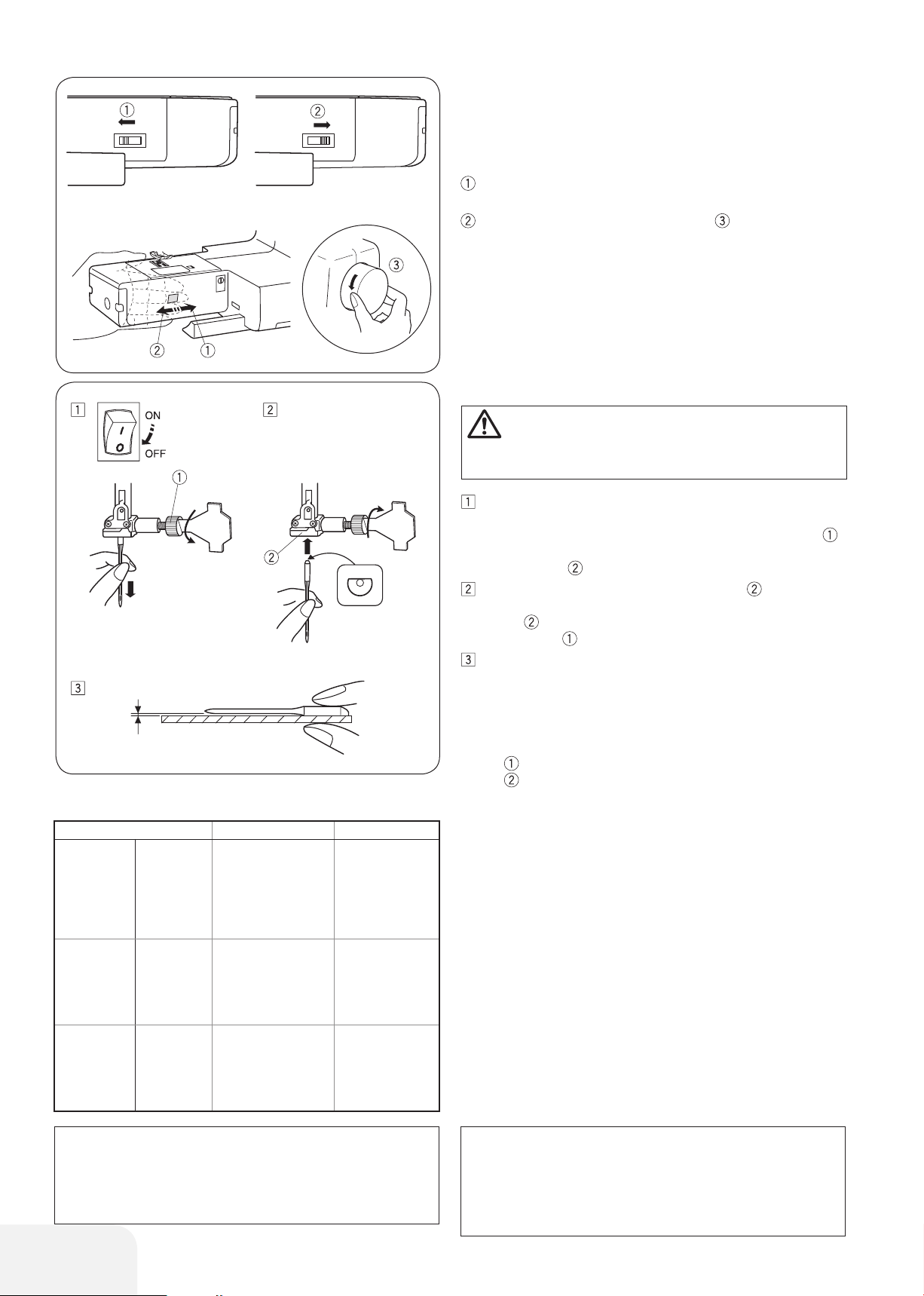
Dropping or Raising the Feed Dog
The drop feed dog lever is located underneath the free arm bed
on the back of the machine.
To drop the feed dog, push the lever in the direction of the arrow
.
To raise the feed dog, push the lever in the direction of the arrow
, as illustrated, and turn the handwheel toward you.
The feed dog must be up for normal sewing.
Changing the needle
CAUTION:
Turn OFF the power switch before changing the needle.
Turn OFF the power switch. Raise the needle to its highest
position by turning the handwheel counterclockwise, and
lower the presser foot. Loosen the needle clamp screw
by turning it counterclockwise. Remove the needle from the
needle clamp .
Insert a new needle into the needle clamp with the flat
side to the rear. When inserting the needle into the needle
clamp , push it up as far as it goes. Tighten the needle
clamp screw firmly by turning it clockwise.
To see if the needle is good, place the flat side of the needle
onto something flat (stitch plate, glass, etc.). The gap
between the needle and the flat surface should be consistent. Never use a bent or blunt needle. A damaged needle
can cause permanent snags or runs in knits, fine silks and
silk-like fabrics.
Needle clamp screw
Needle clamp
Fabric Thread Needle
Lawn
Fine
Medium
Heavy weight
Georgette
Tricot
Organza
Crepe
Sheeting
Jersey
Broadcloth
Fleece
Denim
Tweed
Coating
Quilting
Silk #80-100
Cotton #80-100
Synthetic #80-100
Silk #50
Cotton #50-80
Synthetic #50-80
Silk #30-50
Cotton #40-50
Synthetic #40-50
#9/65-11/75
#11/75-14/90
#14/90-16/100
PLEASE NOTE:
Three no. 14/90 needles are included in the needle set.
For optimal sewing results, it is recommend using Organ
needles.
14
Fabric and Needle Chart
Use a needle size of 11/75 or 14/90 for general sewing work.
A fine thread and needle should be used for sewing lightweight
fabrics, so the fabric will not be marred.
Heavy fabric requires a needle large enough to pierce the fabric
without the needle thread fraying.
Always test the needle size on a small scrap of the fabric that will
be used for actual sewing.
In general, use the same thread for the needle and bobbin.
PLEASE NOTE:
Use a blue shank needle (available separately) when sewing flexible fabrics, very fine fabrics and synthetic fabrics.
The blue shank needle effectively prevents skipped
stitches.
Page 15
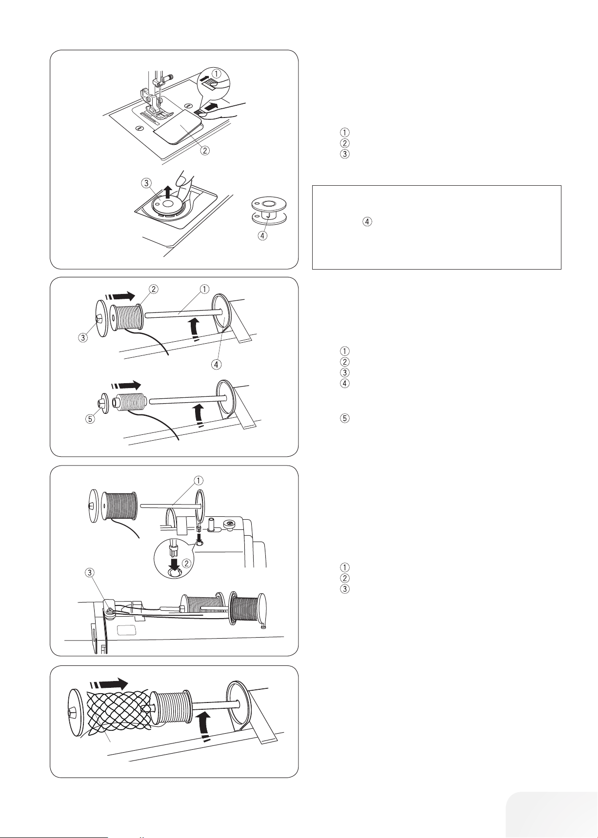
Bobbin Winding and Inserting
• Removing the bobbin
Gently slide the hook cover release button to the right and
remove the hook cover plate.
Lift out the bobbin.
Hook cover release button
Hook cover plate
Bobbin
PLEASE NOTE:
Use the “J” plastic bobbins for horizontal hook (marked
with “J” ). Using other bobbins, such as pre-wound
paper bobbins, may cause stitching problems and/ or damage to the bobbin holder.
• Setting the Spool of Thread
Horizontal spool pin
Lift up the spool pin. Place a spool of thread on the spool pin.
Attach the large spool disc, and press it firmly against the spool
of thread so that the spool rests on the supporter.
Spool pin
Spool
Large spool disc
Supporter
The small spool disc is used with narrow or small spools of
thread.
Small spool disc
Second spool pin
The second spool pin is for winding bobbins without unthreading
the machine.
Insert the second spool pin into the hole.
The second spool pin should point to the bobbin winder tension
disc.
Draw the thread from the spool and pass the thread around the
bobbin winding tension disc as shown.
Second spool pin
Hole for second spool pin
Bobbin winder tension disc
• Spool net
Polyester or bulky nylon threads become loose while unwinding.
To keep consistent feeding of such threads, pull the spool net
over the spool.
15
Page 16
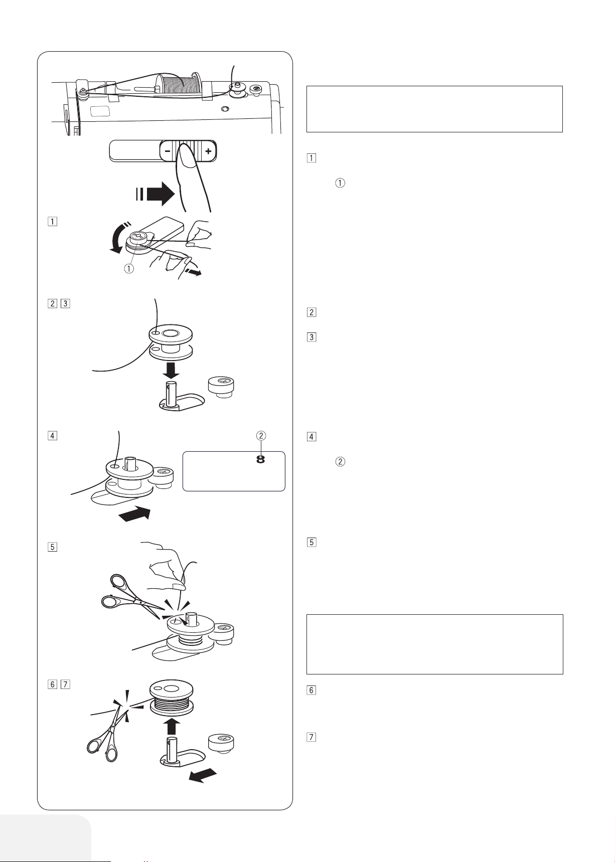
• Bobbin Winding
PLEASE NOTE:
Set the slide speed control at its fastest position for bobbin
winding.
Draw the thread from the spool and pass the thread around
the bobbin winding tension disc.
Bobbin winder tension disc
Thread through the hole in the bobbin from the inside to the
outside.
Put the bobbin on the bobbin winder spindle.
Push the bobbin to the right. The bobbin icon appears on
the LCD display.
Bobbin icon
With the free end of the thread held in your hand, start the
machine. Stop the machine when it has wound a few layers,
and then cut the thread close to the hole in the bobbin.
PLEASE NOTE:
For safety purposes, the machine will automatically
stop 1.5 minutes after starting bobbin winding.
Start the machine. When the bobbin is fully wound, it will
stop automatically. Stop the machine and return the slide
speed control position. Shift the bobbin winder spindle to
the left for stitching. Cut the thread as shown.
Remove the bobbin. Cut the thread as shown. Return the
slide speed control position.
16
Page 17
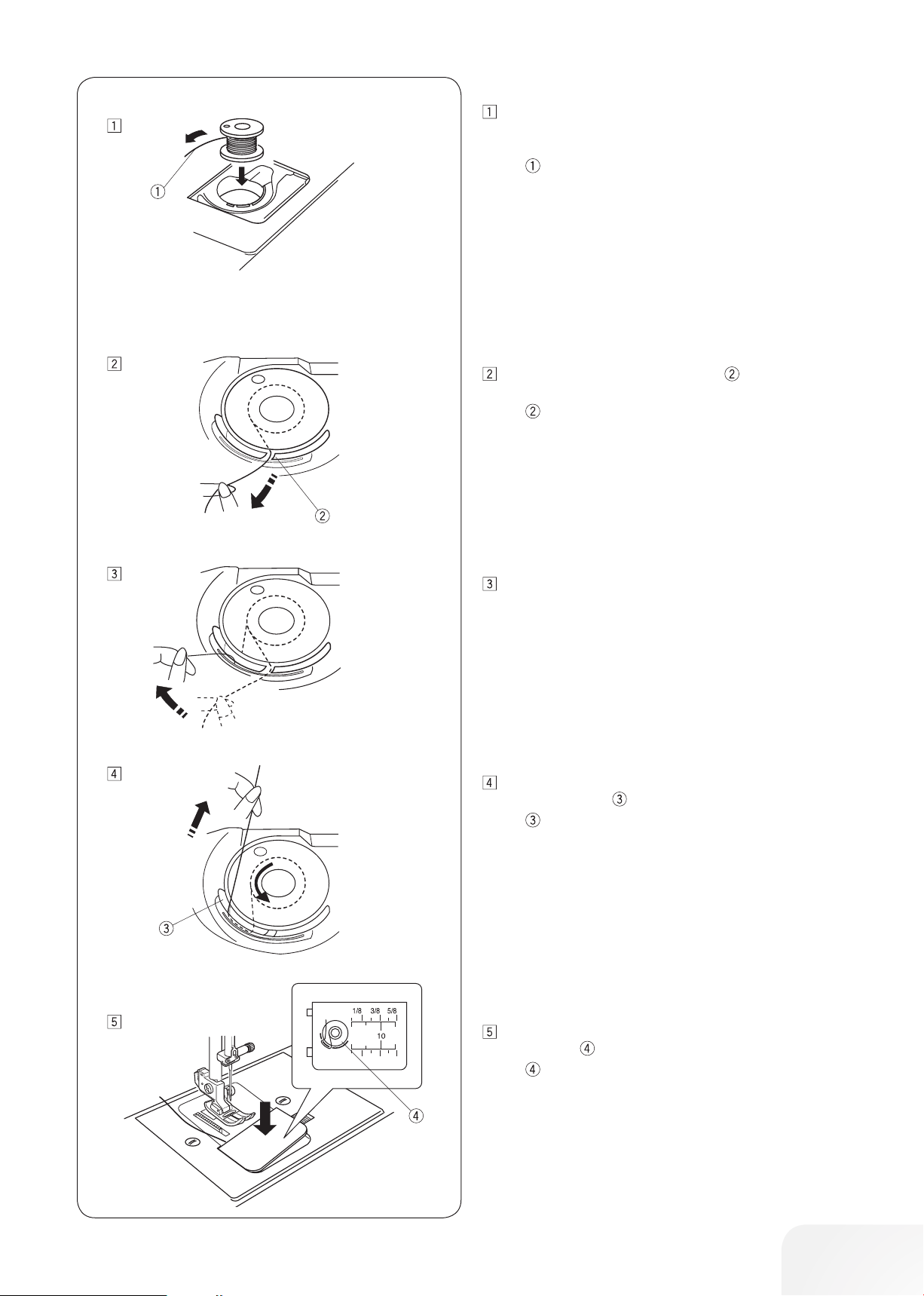
• Insert the bobbin
Put one bobbin on the bobbin winder spindle. Place a bob-
bin in the bobbin holder with the thread running off counterclockwise.
End of thread
Guide the thread into the first notch on the front side of
the bobbin holder.
Notch
Draw the thread to the left, sliding it between the tension
spring blades.
Continue to draw the thread lightly until the thread slips into
the second notch . Pull out about 6˝ (15 cm) of thread.
Notch
Attach the hook cover plate. Check the threading. Refer to
the diagram shown on the hook cover plate.
Threading diagramm
17
Page 18
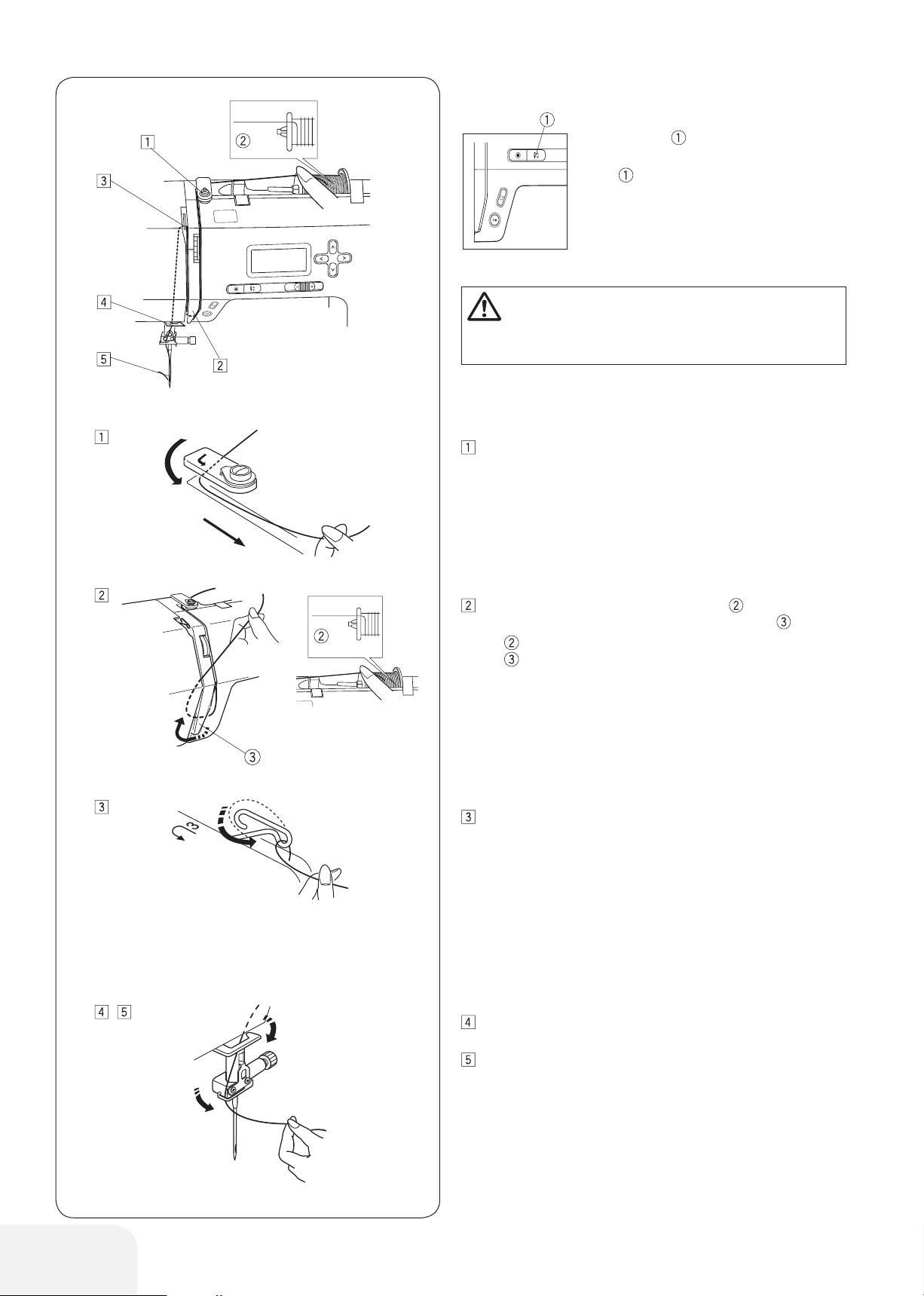
Threading the Machine
Raise the presser foot. Press the needle stop
up/down button to raise the thread take-up
lever to its highest position.
Needle stop up/down button
CAUTION:
Turn OFF the power switch before threading the machine.
• Threading the Machine
Draw the end of the thread around the upper thread guide.
While holding the thread near the spool , draw the end of
the thread down around the check spring holder .
Spool
Check spring holder
Firmly draw the thread up from right to left over the take-up
lever, and down into the take-up lever eye.
Pass the thread through the lower thread guide. Slide the
thread behind the needle bar thread guide on the left.
Thread the needle from front to back, or use the needle
threader.
18
Page 19

CAUTION:
Turn OFF the power switch when using the needle
threader.
Needle threader
Lower the presser foot. Raise the needle to its highest posi-
tion. Pull down the needle threader as far as it will go.
Needle Threader
Turn the needle threader away from you so the hook comes
out through the needle eye. Draw the thread around the
guide and under the hook .
Guide
Hook
Turn the needle threader toward you to pull the thread
through the needle eye. Raise the needle threader in the
direction of the arrow, drawing the thread loop through the
needle.
Pull the thread through the needle eye.
PLEASE NOTE:
The needle threader can be used with a #11 to #16 needle
or a blue shank needle. Thread sizes 50 to 90 are recommended.
19
Page 20

Drawing up the Bobbin Thread
Raise the presser foot. Hold the needle thread lightly with
your left hand.
Press the needle stop up/down button twice to lower and
raise the needle to pick up the bobbin thread.
Needle stop up/down button
Pull both threads 4˝ to 6˝ (10 to 15 cm) under and behind
the presser foot.
20
Page 21

LCD display
The LCD display shows the following information when the
machine is turned on.
Stitch pattern number
Cursors
Stitch width
Stitch length
Presser foot
Press the cursor buttons to move the cursor under the
stitch pattern number.
The cursors appear under both digits when turning the
power on.
Press the value set buttons to change the stitch pat-
tern number until the pattern number of the desired stitch
is indicated.
The number will increase or decrease by 1 each time you
press the value set button.
Press the button to move the cursor under the tens digit
of the stitch pattern number.
The number will increase or decrease by 10 each time you
press the value set button.
Stitch pattern
21
Page 22

Setting Mode
• Auto-o timer
The machine will be turned off if you do not use the machine
within the time period set by this timer.
The auto-off timer can be set from 1 to 12 hours.
The default auto-off timer setting is 7 hours and “07” sign
appears on the screen.
To enter the setting mode, press and hold the needle stop
up/down button and turn the power switch on until the
setting screen "Auto-off timer" is shown (01).
Press or button to increase or decrease the setting
value.
If you wish to turn off the timer, press and hold or but-
ton until “oFF” sign appears on the screen.
Press the start/stop button to apply the setting.
22
PLEASE NOTE:
The auto-off timer is available in EU countries and some
regions which use 200 - 240 voltage standards.
Page 23

Adjusting the Thread Tension for a Straight
Stitch
• Correct tension
Needle thread (top thread)
Bobbin thread (bottom thread)
To loosen tension
To tighten tension
The ideal straight stitch has threads locked between two layers
of fabric, as illustrated (magnified to show detail).
If you look at the top and bottom of the seam, notice that the
stitches are evenly balanced.
When adjusting the thread tension, the higher the number, the
tighter the top thread tension.
Results depend on:
- stiffness and thickness of the fabric
- number of fabric layers
- Stichtyp
• Loosen the Thread Tension
Needle thread (top thread)
Bobbin thread (bottom thread)
To loosen tension
Right side (top side) of fabric
Wrong side (bottom side) of fabric
The bobbin thread shows through on the right side of the fabric,
and the stitch feels bumpy. Turn the dial to a lower tension setting
number to loosen the thread tension.
• Tighten the Thread Tension
Needle thread (top thread)
Bobbin thread (bottom thread)
To tighten tension
Right side (top side) of fabric
Wrong side (bottom side) of fabric
The needle thread shows through on the wrong side of the fabric,
and the stitch feels bumpy. Turn the dial to a higher tension setting number to tighten the thread tension.
23
Page 24

Adjusting the Needle Thread Tension for a
Zigzag Stitch
In an ideal zigzag stitch, the bobbin thread does not show on the
right side (top) of the fabric, and the needle thread shows slightly
on the wrong side (bottom) of the fabric.
See the illustrations for the correct appearance.
To match this appearance, adjust the needle tension as.
• Correct tension
Right side (top side) of fabric
Wrong side (bottom side) of fabric
Minimize the amount of needle thread visible on the wrong side
(bottom side) of the fabric without causing excessive puckering,
or causing the bobbin thread to show on the right side (top side)
of the fabric.
Results vary with fabric, thread and sewing conditions.
• Tension is too tight
Right side (top side) of fabric
Wrong side (bottom side) of fabric
The corner of each zigzag pulls together on the right side of the
fabric.
• Tension is too loose
Right side (top side) of fabric
Wrong side (bottom side) of fabric
The corner of each zigzag point pulls together on the wrong side
of the fabric.
24
Page 25

BASIC SEWING
1
2
3
4
5
6
7
8
9
Straight Stitch sewing
Stitch pattern: 01 or 02
Thread tension: 2 - 6
Presser foot: Zigzag foot
• Starting to sew
Raise presser foot and position the fabric next to a seam guide
line on the stitch plate (5/8˝ (1.6 cm) is most common). Lower the
needle to the point where you want to start. Lower the presser
foot and pull the threads toward the back. Start the machine.
Gently guide the fabric along a seam guide line letting the fabric
feed naturally.
• Changing sewing direction
Stop the machine and bring the needle down into the fabric by
pressing the needle stop up/down button .
Raise the presser foot.
Pivot the fabric around the needle to change the sewing direction
as desired. Lower the presser foot.
Needle stop up/down button
• Finishing sewing
To fasten the ends of a seam, press the reverse sewing button
and sew several Reverse sewing stitches. Raise the presser
foot. Remove the fabric, draw the threads to the back and cut
them with the thread cutter . The threads are cut a proper
length to begin sewing the next seam.
Reverse sewing button
Thread cutter
• Turning square corners
When sewing with fabric edge at 5/8˝ seam guide, to turn a
square corner so that sewing continues at same distance from
edge. Stop the machine when front edge of fabric reaches the
cornering guide lines .
Lower the needle by pressing needle stop up/down button .
Raise the presser foot and turn the fabric counterclockwise 90°.
Lower the presser foot, and begin stitching in the new direction.
Cornering guide
Needle stop up/down button
• Sewing from the edge of thick fabric
The black button on the zigzag foot locks the foot in the horizontal position.
This is helpful when starting to sew from the far edge of thick
fabrics or sewing across a hem. Lower the needle into the
fabric at the point where you wish to start sewing. Lower the foot
while pushing in the black button . The foot is locked in the
horizontal position to avoid slipping.
The button is released automatically after sewing a few stitches.
Black button
Thick fabrics
25
Page 26

• Stitch plate
The seam guides on the stitch plate and the hook cover help you
to measure seam allowance. The numbers on the stitch plate
indicate the distance between the center needle position and
the edge of the fabric .
Center needle position
Edge of the fabric
Number
Distance
Distance
10 15 30 40 3/8 1/2 5/8 1 1 1/2
1.0 1.5 3.0 4.0
(cm)
(inch)
—
3/8 1/2 5/8 1 1 1/2— — — —
— — —
—
The front seam guides are marked at 1/8˝, 3/8˝ and 5/8˝ from
the center needle position .
Front seam guides
• Adjusting the stitch length
Press the cursor buttons to move the cursor under the
stitch length value “2.4” (default setting).
Press the button to decrease stitch length.
Press the button to increase stitch length .
The stitch length can be varied from 0.0 to 5.0.
Cursor
Stitch length (2.4)
PLEASE NOTE:
Reverse sewing stitch length cannot be set longer than
4.0.
• Adjusting the needle position
The needle position can be adjusted for straight stitch patterns
01–03, 07, 14, 35 and 36.
Press the cursor buttons to move the cursor under the
stitch width value “3.5” (default setting).
Press the button to move the needle to the left .
Press the button to move the needle to the right .
Cursor
Left (0.0)
Middle (3.5)
Right (7.0)
26
Page 27

Straight stitch
1
2
3
4
5
6
7
8
9
7
8
9
17
18
19
4A5A6A7A8A9
A
14
15
16
4
5
6
7
8
9
Stitch pattern: 01 or 02
Thread tension: 2 - 6
Presser foot: Zigzag foot
For seaming garments, zipper application and more.
Securing stitch
Stitch pattern: 07
Thread tension: 2 - 6
Presser foot: Zigzag foot
Reverse sewing button
Use this stitch to secure the beginning and the end of a seam
with backstitching.
When you reach the end of the seam, press the reverse sewing
button once. The machine will sew four reverse sewing
stitches, four forward stitches, and then stop sewing automatically.
Locking Stitch
Stitch pattern: 14
Thread tension: 2 - 6
Presser foot: Zigzag foot
Reverse sewing button
This unique stitch is used where an invisible locking stitch is
needed.
Lower the needle close to the front edge of the fabric.
The machine will sew several locking stitches in place and continue sewing forward.
When you press the reverse sewing button at the end of the
seam, the machine will sew several locking stitches in place,
then stop sewing automatically.
Stretch Stitch
Stitch pattern: 04
Thread tension: 3 - 6
Presser foot: Zigzag foot
This stitch is a narrow stretch stitch designed to eliminate puckering on knit fabrics and bias seams, while permitting the seam
to be pressed completely open flat.
27
Page 28

Triple straight stitch
3
4
5
6
7
8
9
17F18
R
35
19
R
36
37
38
5
A
39
6A7A8
A
25
F
9
A
26F27F28F29
F
15
F16F
17F18R19
R
36
37
38
39
6A7A8A9
A
26F27F28F29
F
16
F
Stitch pattern: 03
Thread tension: 2 - 6
Presser foot: Zigzag foot
This strong, durable stitch is recommended when both elasticity
and strength are necessary in order to insure comfort and durability. Use it to reinforce areas such as crotch and armhole
seams. Also use for extra reinforcement when constructing items
such as backpacks.
Sculpture Stitch
Stitch pattern: 35
Thread tension: 3 - 6
Presser foot: Satin stitch
For top stitching and outlining designs.
Sew slowly at the corners.
Saddle Stitch
Stitch pattern: 36
Thread tension: 3 - 6
Presser foot: Zigzag foot
This saddle stitch is formed with one stitch forward, two stitches
backward, and a fourth stitch forward.
You can achieve a lovely hand-worked look when topstitching
suits, blazers, jumpers, and denim outfits with the saddle stitch.
28
Page 29

Zigzag
5
6
7
8
9
Stitch pattern: 05
Thread tension: 2 - 6
Presser foot: Zigzag foot
The zigzag stitch is one of the most useful and versatile stitches.
It is used for overcasting, darning, appliqué, and also used as a
decorative stitch.
PLEASE NOTE:
Use an interfacing when sewing on stretch fabrics such as
knit, jersey or tricot.
• To adjust the stitch width
Press the cursor buttons to move the cursor under the
stitch width value “3.5” (default setting).
Press the button to decrease stitch width .
Press the button to increase stitch width .
The stitch width can be varied from 0.0 to 7.0.
• Adjusting the stitch length
Press the cursor buttons to move the cursor under the
stitch length value “1.5” (default setting).
Press the button to decrease stitch length .
Press the button to increase stitch length .
The stitch length can be varied from 0.2 to 5.0.
29
Page 30

3-step zigzag
6
7
8
9
0
R
17
1
A
18
2
A
19
3A4A5A6A7A8A9
A
10
11
12
13
14
15
16
17
1
A
18
2
A
19
3A4A5A6A7A8A9
A
11
12
13
14
15
16
8
9
Stitch pattern: 06
Thread tension: 3 - 6
Presser foot: Zigzag foot
This stitch is used to finish seams on synthetics and other fabrics
that tend to pucker. The stitch is also excellent for darning and
mending tears.
Place your fabric to allow a 5/8˝ (1.5 cm) seam.
Trim excess close to stitching. Be careful not to cut the stitches.
Stretch Overlock
Stitch pattern: 10
Thread tension: 3 - 6
Presser foot: Zigzag foot
Place your fabric to allow a 5/8˝ (1.5 cm) seam. Trim excess
close to stitching. Be careful not to cut the stitches.
Overlock Stitches
Machine setting
Stitch pattern: 8 or 11
Thread tension: 3 - 7
Presser foot: Zigzag foot
Carefully guide the fabric so the needle falls off the edge when it
swings to the right.
30
Page 31

Various Kinds of Buttonholes and Their Uses
0
1
2
3
4
5
6
7
8
9
18
19
8A9
A
19
9
A
0
R
17
F
1
A
18
R
2
A
19
R
3
A
20
4
A
21
5
A
22
6
A
23
7
A
24
8
A
25
9
A
26
10
A
27
11
A
28
12
A
29
13F14A15
F16F
Standard Buttenhole
This standard buttonhole is widely used on medium to heavy
fabrics. The buttonhole size is automatically determined by placing a button in the buttonhole foot with slide.
Round-End Buttonhole
This buttonhole is used on medium to heavy weight fabrics,
especially for blouses and children’s clothes.
Keyhole Buttonhole
The keyhole buttonhole is widely used on medium to heavy fabrics. It is also suitable for larger and thicker buttons.
Stretch Buttonhole
This buttonhole is suitable for stretch fabrics. It can also be used
as a decorative buttonhole.
PLEASE NOTE:
To sew the buttonholes 18 to 20, follow the same procedure as standard buttonhole (See pages 32 to 33).
The size of a buttonhole is automatically set by placing a
button in the rear of the buttonhole foot with slide R.
The button holder of the foot takes a button size of up to 1˝
(2.5 cm) in diameter.
It is sometimes necessary to change buttonhole size to
match certain heavy or specific materials and threads.
Make a test buttonhole on an extra piece of the fabric to
check your setting.
Place the button on the fabric and mark the top and bottom
to determine the position of the buttonhole on the fabric.
Use interfacing on stretch fabrics.
31
Page 32

Standard Buttenhole
0
1
2
3
4
5
6
7
8
9
Stitch pattern: 00
Thread tension: 1 - 5
Presser foot: Buttonhole foot with slide
Buttonhole lever sign
• To sew
Press the needle stop up/down button to raise the needle.
Attach the buttonhole foot with slide R snapping the pin
into the groove of the presser foot holder.
Groove
Pin
Pull the button holder to the back, and place the button
in it. Push it together tightly against the button.
PLEASE NOTE:
If the button is extremely thick, make a test buttonhole on
an extra piece of the fabric.
If it is difficult to fit the button through the test buttonhole,
you can lengthen the buttonhole by pulling the button
holder back a little. The length of the buttonhole will be
increased.
Button holder
Extra gap
Pull the buttonhole lever down as far as it will go.
Buttonhole lever
Insert the corner of the fabric under the foot. Press the
needle stop up/down button twice. Remove the fabric to the
left to draw the needle thread through the hole of the foot.
Place the fabric under the foot, and lower the needle at the
starting point of the buttonhole mark . Then lower the buttonhole foot with slide R.
Buttonhole mark
Starting point
Slider
Stopper
PLEASE NOTE:
Make sure that is no gap between slider and stopper.
Otherwise the buttonhole is not sewn properly.
No gap
Sewing gap
32
Page 33

Start the machine to sew the buttonhole.
The buttonhole will be automatically sewn.
The machine will sew the left row first.
The machine will sew the back bartack and the right row.
The machine will sew the front bartack, then it stops auto-
matically.
PLEASE NOTE:
If you start sewing the buttonhole without lowering the buttonhole lever, the LCD display will show “bL” message and
the buttonhole lever sign will blink.
Lower the buttonhole lever, then restart the machine.
Remove the fabric and place a pin just below the bartack
at each end to prevent accidentally cutting stitches. Cut the
opening with the seam ripper .
Pin
Seam ripper
When buttonhole sewing is finished, push the buttonhole
lever upward as far as it will go.
Buttonhole lever
33
Page 34

Adjusting the Stitch Width and Density for
Buttonholes
• To adjust the stitch width
Press the cursor buttons to move the cursor under the
stitch width value “5.0” (default setting).
Press the button to decrease stitch width .
Press the button to increase stitch width.
The stitch width can be varied from 2.5 to 7.0 depending on the
selected buttonhole.
• Adjusting the stitch density
Press the cursor buttons to move the cursor under the
stitch density value “0.4” (default setting).
Press the button to make the buttonhole stitch dense .
Press the button to make the buttonhole stitch less dense .
The stitch density can be varied from 0.2 to 0.8 depending on the
selected buttonhole.
34
Page 35

Round-End Buttonhole
18
19
8A9
A
19
9
A
0
R
17
F
1
A
18
R
2
A
19
R
3
A
20
4
A
21
5
A
22
6
A
23
7
A
24
8
A
25
9
A
26
10
A
27
11
A
28
12
A
29
13F14A15
F16F
Stitch pattern: 18
Thread tension: 1 - 4
Presser foot: Buttonhole foot with slide
Sewing procedure is the same as standard buttonhole.
The stitch width can be varied from 2.5 to 5.5.
To change the stitch width or stitch density, refer to page 34.
Keyhole Buttonhole
Stitch pattern: 19
Thread tension: 1 - 4
Presser foot: Buttonhole foot with slide
Sewing procedure is the same as standard buttonhole.
Use the seam ripper and an eyelet punch to open the buttonhole.
Eyelet punch*
The stitch width can be varied from 5.5 to 7.0.
To change the stitch width or stitch density, refer to page 34.
* special accessory
Stretch Buttonhole
Stitch pattern: 20
Thread tension: 1 - 4
Presser foot: Buttonhole foot with slide
The machine will sew the front bartack and left row first.
The machine will sew the back bartack, the right row and will
stop automatically.
The stitch width can be varied from 2.5 to 7.0.
The stitch density can be varied from 0.5 to 1.0.
To change the stitch width or stitch density, refer to page 34.
35
Page 36

Buttonhole with cord
0
1
2
3
4
5
6
7
8
9
Stitch pattern: 00
Thread tension: 1 - 5
Presser foot: Buttonhole foot with slide
Use the same procedure as the standard buttonhole proce-
dure. Set the stitch width to match the thickness of the cord
used.
With the buttonhole foot raised, hook the filler cord on the
spur at the back of the buttonhole foot. Bring the ends
toward you under the buttonhole foot, clearing the front end.
Hook the filler cord into the forks on the front of the buttonhole foot with slide to hold them tight.
Lower the needle into the garment where the buttonhole will
start, and lower the foot.
Spur
Forks.
Start the machine and sew the buttonhole. Both sides of the
buttonhole and the bartacks are sewn over the filler cord.
Remove the fabric from the machine, and cut the sewing
threads only.
Needle thread (top thread)
Bobbin thread (bottom thread)
Pull the loose ends of the filler cord to tighten it. Thread the
end of the cord through a hand-sewing needle. Then draw
them to the wrong side of the fabric and knot.
PLEASE NOTE:
Cut the filler cord at both ends, if the filler cord is stitched
on the fabric and cannot be pulled.
36
Page 37

Darning program
17
F
1
A
18
R
2
A
19
R
3A4
A
21
5
A
22
6
A
23
7
A
24
8
A
25
9
A
26
27
11
A
28
12
A
29
13F14A15
F16F
Stitch pattern: 21
Thread tension: 3 - 6
Presser foot: Buttonhole foot with slide
• Starting to sew
Pull the button holder to the back.
Place the garment under the foot. Press the needle stop up/
down button twice. Move the fabric to the left to draw both
threads under the foot.
Lower the foot and start the machine. The machine will lock
stitch, sew 16 rows of darning, lock stitch again and stop
automatically.
Turn the fabric and repeat sewing.
Button holder
Starting point
3/4˝ (2 cm)
9/32˝ (0.7 cm)
• Sewing a shorter darning
To sew a darning shorter than 3/4˝ (2 cm), first stop the machine
after sewing the required length , then press the reverse sewing button .
The required length has been determined.
Start the machine again and continue sewing until the machine
stops automatically.
Reverse sewing button
Required length
Starting point
• Sewing a same-sized darning
Simply start the machine to sew another darning at the same
size.
• Darning balance
Correct the evenness of the darning as follows:
Press the cursor buttons to move the cursor under the
value “d5” (default setting).
When the right side of the darn is lower than the left side, press
the button to set the value to “d6” – “d9”, and make the darn
even.
When the left side of the darn is lower than the right side, press
the button to set the value to “d1” – “d4”, and make the darn
even.
37
Page 38

Bartack
17F18
R
2
A
19
R
3A4A5
A
22
6
A
23
7
A
24
8
A
25
9
A
26
27
28
12
A
29
13F14A15
F16F
17F18R19
R
3A4A5A6
A
23
7
A
24
8
A
25
9
A
26
27
28
29
13F14A15
F16F
Stitch pattern: 22
Thread tension: 3 - 6
Presser foot: Satin stitch foot
The bartack is used to reinforce pockets, crotches and belt carriers where extra strength is needed.
• Starting to sew
Start the machine and sew until the machine stops automatically.
The machine will sew a bartack 5/8˝ (1.5 cm ) long.
5/8˝ (1.5 cm)
• Sewing shorter bartack
* Set the slide speed control at low speed setting.
To sew a bartack shorter than 5/8˝ (1.5 cm), first stop the
machine after sewing the required length , then press the
reverse sewing button .
The bartack length has been determined.
Start the machine again and continue sewing until the machine
stops automatically.
Required length
Reverse sewing button
Bartack length
Starting point
• Sewing a same-sized bartack
Simply start the machine to sew another bartack at the same
size.
Eyelet
Stitch pattern: 23
Thread tension: 1 - 4
Presser foot: Satin stitch foot
The eyelet is used for belt holes etc.
Starting to sew
Attach the satin stitch foot F.
Start the machine. The machine will stop automatically when
completed.
Open the eyelet with an awl, eyelet punch or pointed scissors.
38
• Adjusting the shape of an eyelet
Correct the shape of the eyelet as follows:
Press the cursor buttons to move the cursor under the
value “L3” (default setting) .
If the eylet is stretched , press the button to make the darn
even. (L1~L2)
If the eylet overlaps , press the button to make the darn
even. (L4~L5)
PLEASE NOTE:
The shape can be adjusted within L1 to L5 (default setting
is L3).
Page 39

Zipper Sewing
1
2
3
4
5
6
7
8
9
Stitch pattern: 01
Thread tension: 1 - 4
Presser foot: Zigzag foot
Zipper foot
• Attaching the zipper foot
Fit the pin on the zipper foot into the groove in the presser
foot holder.
To sew the left-side of the zipper, attach the zipper foot with the
right-hand side of the pin .
To sew the right-side of the zipper, attach the zipper foot with the
left-hand side of the pin .
Groove
Pin
To sew left side
To sew right side
• Fabric preparation
Add 3/8˝ (1 cm) to the zipper length. This is the overall opening
size.
Right side of the fabric
3/8˝ (1 cm)
Opening size
Zipper length
Slider
Zipper teeth
Zipper tape
Wrong side of the fabric
End of the opening
Lay the foreheads of the fabric together and sew until the end of
the zipper opening. Taken into account in a seam allowance of
13/16˝ (2 cm). Reverse the stitch to fasten the seam. Attach the
zigzag foot. Baste along the zipper opening with the stitch length
4.5.
2 cm (13/16˝)
Zipper opening (Basting)
Reverse sewing stitches
End of the opening
Seam
PLEASE NOTE:
Loosen the thread tension to one (1) for basting.
• Starting to sew
Fold up the upper seam allowance. Fold back the bottom
seam allowance to form a 1/8˝ (0.3 cm) fold.
Place the zipper teeth next to the fold and pin it in place.
Bottom fabric
End of the zipper opening
Zipper teeth
1/8˝ (0,3 cm)
Wrong side of the upper fabric
Opening size
Fold
39
Page 40

Attach the zipper foot with the pin on the right. Sew through
all the layers from the end of the zipper opening, guiding the
zipper teeth along the edge of the foot. Stop the machine
2˝ (5 cm) before the foot reaches the slider on the zipper
tape. Lower the needle into the fabric, and raise the foot.
Open the zipper, then lower the foot and stitch the remainder of the seam.
Slider
2˝ (5 cm)
Close the zipper and open the upper fabric flat over the zip-
per. Baste the upper fabric and zipper tape together.
Basting stitch
Attach the zipper foot with the pin on the left. Sew reverse
stitches 3/8˝ (1 cm) over the end of the zipper opening. Turn
the fabric 90 degrees and stitch through the garment and
zipper tape.
Reverse stitches
Stop the machine 2˝ (5 cm) before the foot reaches the
slider on the zipper tape. Lower the needle into the fabric,
and raise the foot. Remove the basting stitches.
Basting stitch
40
Open the zipper, then lower the foot and stitch the remain-
der of the seam.
After finished sewing, remove the basting stitches on the
upper fabric.
Page 41

Blindstitch
9
Stitch pattern: 09
Thread tension: 1 - 4
Presser foot: Zigzag foot
Fold a hem with the wrong side of the fabric up to form a
1/4˝ – 7/16˝ (0.4 – 0.7 cm) allowance.
Wrong side of the fabric
1/4˝ – 7/16˝ (0.4 – 0.7 cm)
(1) On heavyweight fabrics that tend to ravel, the raw edge
should be overcast first.
(2) Fold the hem under the fabric for lightweight fabrics.
Position the fabric, so that the needle at its leftmost posi-
tion just pierces the edge of the fold.
When the needle comes to the left
When the needle comes to the right
Open the fabric after sewing is finished.
PLEASE NOTE:
If the needle pierces too far left, the stitch will show
through on the right side of the fabric.
41
Page 42

Button Sewing
Stitch pattern: 05
Thread tension: 3 - 7
Presser foot: Buttonhole sew-on foot T
Feed dog: Lowered
CAUTION:
Turn OFF the power switch before changing the foot.
Lower the feed dog. Set the slide speed control at low
speed setting.
Place the presser foot so that the back pin on the foot lines
up directly below the back notch of the presser foot holder.
Back pin
Notch on presser foot holder
Lower the presser foot holder and help with fingers to hold
der presser foot until it place. Raise the presser foot.
Place the button on the fabric, turn the handweel and pierce
the needle in the left buttonhole.
Hold the button in position by lowering the presser foot and
align the holes from the button horizontally to the presser
foot.
Turn the handwheel so that the needle will enter the right
hole of the button. Readjust the stitch width if necessary.
Stitch several times.
After the sewing process has finished, cut the thread. Keep
3 – 4 cm of the thread on the knob.
With a hand sewing needle, draw the top thread to the
reverse side of the fabric and knot the threads.
* After the button sewing is completed, raise the feed dog
for normal sewing.
42
Page 43

17
18
19
5A6A7A8A9
A
15
16
Attaching Elastic
17
18
2
A
19
3A4A5A6A7A8A9
A
12
13
14
15
16
Stitch pattern: 12
Thread tension: 3 - 7
Presser foot: Satin stitch foot
Mark the elastic into quarters. Match those to the center front,
center back and side seams, and pin the elastic to the fabric.
Place the elastic under the foot and stitch into place while stretch
the elastic evenly.
DECORATIVE STITCHING
Vari-Overlock (Scallop seam)
Stitch pattern: 15
Thread tension: 6 - 8
Presser foot: Satin stitch foot
Use a lightweight fabric (tricot, for example). Fold the fabric as
shown and stitch on the fold. Allow the needle to just pierce next
to the folded edge to create a Vari-Overlock edge. The thread
tension may need to be increased slightly.
The Vari-Overlock can also be sewn in any direction on knitted
fabrics or fabrics with a soft and smooth texture.
43
Page 44

Appliqué
5
6
7
8
9
17F18R19
R
4A5A6A7
A
24
8
A
25
9
A
26
27
28
29
14A15
F16F17F18R19R
5A6A7A8
A
25
9
A
26
27
28
29
15
F16F17F18R19R
6A7A8A9
A
26
27
28
29
16
F
17F18R19
R
37
38
39
7A8A9
A
27F28F29
F
Stitch pattern: 5, 24, 25 or 26
Thread tension: 1 - 4
Presser foot: Satin stitch foot
* The stitch width of pattern 5, 24, 25 or 26 can be changed
without changing it’s center needle position.
Place an appliqué on the fabric and baste or pin it in place.
Sew while guiding the fabric so the needle falls along the outer
edge of the appliqué.
Appliqué
Outer edge
• To adjust the stitch width
Select pattern 24.
Press the cursor buttons to move the cursor under the
stitch width value “3.5” (default setting).
Press the button to decrease stitch width .
Press the button to increase stitch width .
The stitch width will be varied based on the centered needle
position .
Stitch width (3.5)
Stitch pattern 24 (stitch width decreased)
Stitch pattern 24 (stitch width increased)
Center needle position
44
Scallop Stitch
Stitch pattern: 37
Thread tension: 3 - 6
Presser foot: Zigzag foot
* Stitch pattern 45 can also be used.
Sew the stitches approximately 3/8˝ (1 cm) inside the edge of the
fabric.
Trim the outside of the stitches as shown. Make sure you don’t
cut the thread.
Page 45

Smocking
1
2
3
4
5
6
7
8
9
17
18
19
7A8A9
A
Stitch pattern: 01 and 17
Thread tension: 3 - 6
Presser foot: Satin stitch foot
Smocking is a delicate decorative treatment used on children’s
clothes or women’s blouses.
Choose a soft and lightweight fabric, e.g. batiste. Cut the fabric
three times wider than the projected width. Set stitch length at
“5.0” and sew rows of straight stitches 3/8˝ (1.0 cm) apart across
the area to be smocked.
PLEASE NOTE:
Pull up the bobbin thread and draw a 4˝ to 6˝ thread tail to
the back under the presser foot before start sewing.
Knot the threads along one edge . From the other edge, pull
the bobbin threads (bottom threads) to distribute the gathers
evenly.
Sew the smocking stitches between the gathered rows.
Remove the straight stitches by pulling them out.
Knotted edge
Gathers
PLEASE NOTE:
A similar effect can be achieved by using an elastic thread
as the bottom thread. Wind the elastic thread by hand. Use
a straight stitch.
45
Page 46

171819
3A4A5A6A7A8A9
A
131415
16
171819
6A7A8A9
A
16
17
F
34
1
A
18
R
35
2
A
19
R
36
3
A
37
4
A
21
R
38
5
A
22
F
39
6
A
23
F
7
A
24
F
8
A
25
F
9
A
26F27
F
11
A
28
F
12
A
29
F
13F14
A
31
15
F
32
16
F
33
Patchwork Piecing
17
F
34
18
R
35
19
R
36
3
A
37
4
A
38
5
A
39
6
A
23
F
7
A
24
F
8
A
25
F
9
A
26F27F28F29
F
13F14A15
F16F
33
171819
3A4A5A6A7A8A9
A
131415
16
1
2
3
4
5
6
7
8
9
17
F
34
18
R
35
2
A
19
R
36
3
A
37
4
A
38
5
A
22
F
39
6
A
23
F
7
A
24
F
8
A
25
F
9
A
26F27F28
F
12
A
29
F
13F14A15
F
32
16
F
33
Stitch pattern: 01 and 32
Thread tension: 3 - 6
Presser foot: Zigzag foot
Place the patchwork pieces right sides together. Select
stitch pattern 01. Sew a precise 1/4˝ (0,6 cm) seam allowance.
Wrong side of the fabric
Right side of the fabric
Select stitch pattern 32.
Press the seam allowance to open.
Sew stitch pattern 32 on the right side of the garment cen-
tering over the seam line.
* Stitch patterns 13, 33, 34
can also be used.
Fagoting
Stitch pattern: 31
Thread tension: 3 - 6
Presser foot: Satin stitch foot
Use this stitch to join two pieces of fabric to create an open work
appearance and add design interest.
Fold under each fabric edge 5/8˝ (1.5 cm) and press. Pin the two
edges to paper or tear backing 1/8˝ apart. Sew slowly, guiding
the fabric so the needle catches the folded edge on each side.
After finishing the sewing, take off the paper.
* Stitch patterns 13, 16
0,3 - 0,4 cm (1/8˝)
Paper
can also be used.
46
Page 47

0
R
17
F
34
F
1
A
18
R
35
F
2
A
19
R
36
A
3
A
20
R
37
A
4
A
21
R
38
F
5
A
22
F
39
F
6
A
23
F
40
7
A
24
F
41
8
A
25
F
42
9
A
26
F
43
10
A
27
F
44
11
A
28
F
45
12
A
29
F
46
13
F
30
F
47
14
A
31
F
48
15
F
32
A
49
16
F
33
F
17
F
34
F
18
R
35
F
2
A
19
R
36
A
3
A
37
A
4
A
38
F
5
A
22
F
39
F
6
A
23
F
7
A
24
F
8
A
25
F
42
9
A
26
F
43
27
F
44
28
F
45
12
A
29
F
46
13
F
47
14
A
48
15
F
32
A
49
16
F
33
F
Quilt Stitch
Stitch pattern: 40
Thread tension: 3 - 6
Presser foot: Satin stitch foot
A pre-programmed stippling stitch is a fast and easy method to
quilt small areas.
Place a batting (wadding) between quilt top and backing fabric.
Satin Stitches
Stitch pattern: 45
Thread tension: 3 - 6
Presser foot: Satin stitch foot
* Stitch patterns 42–44 and 46 can be used for satin stitches.
For better sewing results, interfacing should be used on the
wrong side of the fabric when you use stretch or elastic fabrics.
Press the auto-lock button to finish the end of the pattern.
47
Page 48

Fringing
17F18R19
R
4A5A6A7
A
24
8
A
25
9
A
26
27
28
29
14A15
F16F
17F18R19
R
4A5A6A7
A
24
8
A
25
9
A
26
27
28
29
14A15
F16F
Stitch pattern: 24
Thread tension: 3 - 6
Presser foot: Satin stitch foot
Fringing adds a special touch on table linens and shawls.
Choose a firm, woven fabric like linen where threads can be
removed easily.
Carefully cut the fabric on the grain. Remove a single strand
of yarn or thread where the fringing is to begin.
Sew down the left side so the right hand stitches fall in the
open space.
Remove all excess yarn located to the right of the stitching
and create a fringe.
Drawn work
Stitch pattern: 24
Thread tension: 3 - 6
Presser foot: Satin stitch foot
Drawn work uses the same method as fringing. Choose a firm,
woven fabric like linen where threads can be removed easily.
Carefully cut the fabric on the grain. Determine the width of
the drawn work and remove one strand of yarn or fabric
thread at each end.
Sew down the left side, guiding the fabric so the right hand
stitches fall in open space. After finishing the left side, turn
the fabric around 180°. Sew down the other side.
48
Remove the yarn or fabric threads between the stitching.
Page 49

Cross stitch
19
R
39
9
A
29
F
17
18
2
A
19
3A4A5A6A7A8A9
A
121314
15
16
18R19
R
8A9
A
28
29
17F18R19
R
7A8A9
A
272829
19
R
9
A
29
0
R
17
F
34
1
A
18
R
35
2
A
19
R
36
3
A
20
R
37
4
A
21
R
38
5
A
22
F
39
6
A
23
F
7
A
24
F
8
A
25
F
9
A
26
F
10
A
27
F
11
A
28
F
12
A
29
F
13
F
30
14
A
31
15
F
32
16
F
33
18R19
R
38
39
8A9
A
28F29
F
19
R
39
F
9
A
29
F
49
18R19
R
38F39
F
8A9
A
28F29
F
48
49
17
F
34
F
1
A
18
R
35
F
2
A
19
R
36
A
3
A
37
A
4
A
21
R
38
F
5
A
22
F
39
F
6
A
23
F
7
A
24
F
41
8
A
25
F
42
9
A
26
F
43
27
F
44
11
A
28
F
45
12
A
29
F
46
13
F
47
14
A
31
F
48
15
F
32
A
49
16
F
33
F
Stitch pattern: 39
Thread tension: 3 - 6
Presser foot: Satin stitch foot
You can make cross stitch designs with these patterns, in half the
time it would take if embroidered by hand.
* If you press the auto-lock button before sewing, the machine
will sew one unit of the cross stitch and stop automatically.
Choose a plain close weave fabric such as linen or wool flannel
for the background fabric. If you choose light weight fabric, use a
tear away backing for support.
Adjust the stitch width and length as you desire to match the
pattern.
Find the center of the design, or if the design is a border, choose
a starting point.
Use auto-lock button to begin and end.
Decorative Stitches
Stitch pattern: 12, 27–30, 38, 41, 48 or 49
Thread tension: 3 - 6
Presser foot: Satin stitch foot
For the best sewing results, carefully align and guide the fabric
when you sew with decorative stitches.
Use a tear-way backing if necessary.
49
Page 50

Decorative Stitch Combinations
19
R
39
F
9
A
29
F
49
17
F
34
F
18
R
35
F
19
R
36
A
3
A
37
A
4
A
38
F
5
A
39
F
6
A
23
F
7
A
24
F
8
A
25
F
9
A
26
F
43
27
F
44
28
F
45
29
F
46
13
F
47
14
A
48
15
F
49
16
F
33
F
Stitch pattern: 43 and 49
Thread tension: 3 - 6
Presser foot: Satin stitch foot
Example:To combine two units of pattern 43 and 49.
Sew pattern 43 and press the auto-lock button while sewing
the second unit. The machine will stop automatically when
the second unit is completed.
Auto-lock button
Select stitch pattern 49. Use auto-lock button to start sew-
ing.
Machine will sew one unit of pattern 43 and stop automati-
cally.
Repeat the procedure above.
Balance
The sewing results of the stretch patterns may vary depending
upon the sewing conditions, such as sewing speed, type of the
fabric, number of layers etc.
Always test sew on a scrap piece of the fabric that you wish to
use.
If stretch patterns are distorted, correct it with the balance.
Balance
• Stretch stitch pattern
If the pattern is compressed, turn the balance in the direction of
“+”.
If the pattern is drawn out, turn the balance in the direction of “–”.
• Evenness of Bartack
If the stitch does not meet start position, turn the feed
balancing dial in the direction of “+”.
If the stitch does not meet return position, turn the balance in the
direction of “–”.
50
Page 51

CARE OF YOUR MACHINE
Cleaning the Hook Race and Feed Dog
WARNING:
Turn the power switch off and unplug the machin before
cleaning.
The machine must only be disassembled as described in
this section.
CAUTION:
Do not store the machine in a high-humidity area, near a
heat radiator, or in direct sunlight.
PLEASE NOTE:
Clean the outside of the machine with a soft cloth and
soap. After cleaning the machine, make sure the needle
and presser foot are attached.
Press the needle stop up/down button to raise the needle. Turn
off the power switch.
Remove the needle and presser foot.
Remove the cover plate by sliding the cover plate release button
to the right. Take out the bobbin. Brush out dust and lint. (You
may also use a vacuum cleaner.)
Remove the setscrew out of the stitch plate . Use the
T-screwdriver supplied with the machine. Remove the
stitch plate .
Lift up the bobbin holder and remove it.
Clean the bobbin holder with a lint brush .
Clean the feed dog and hook race with the lint brush.
Clean the center of the hook race with a dry cloth.
T screwdriver
Setscrews
Stitch plate
Lint brush
Bobbin holder
Feed dog
Hook race
* The machine does not require oiling.
Installing the Bobbin Holder
Insert the bobbin holder so that the knob fits next to
the stopper in the hook race.
Insert the bobbin.
Attach the stitch plate with the setscrews . After cleaning
the machine, make sure the needle and presser foot are
attached.
Bobbin holder
Stopper
Knob
T screwdriver
Setscrews
51
Page 52

Problems and Warning Signs
Warning sign
Cause
The start/stop button is pressed with the foot control
connected.
The foot control is out of order.
(The foot control sign keeps blinking.)
The machine will stop if the buttonhole is sewn without lowering the buttonhole lever.
The bobbin winder spindle is shifted to the right. Shift the bobbin winder spindle to
The machine is started after halting due to overload. Wait for at least 15 seconds to
Disconnect the foot control.
Contact the service center or the
store from whom the machine was
purchased.
Lower the buttonhole lever and
start the machine again.
the left for stitching.
restart.
Switch off the power switch.
Remove tangled threads around
take-up lever, hook race.
Remedy
Audible signal
Pip
Pip-pip-peep
Pip-pip-pip
Peep
The buzzer sounds when:
Normal operation
Invalid operation
Buttonhole sewing completed
Malfunction
52
Page 53

Troubleshooting
Condition Cause
The needle thread breaks
The bobbin thread breaks
The needle breaks
Skipped stitches
1. The thread is not threaded properly.
2. The thread tension is too tight.
3. The needle is bent or blunt.
4. The needle is incorrectly inserted.
5. The needle thread and the bobbin thread are not set under the
presser foot when start sewing.
6. The threads were not drawn to the rear after sewing.
7. The thread is either too heavy or too fine for the needle.
1. The bobbin thread is not threaded properly in the bobbin holder.
2. Lint has collected in the bobbin holder.
3. The bobbin is damaged and doesn’t turn smoothly.
4. The thread is wound loosely on a bobbin.
1. The needle is incorrectly inserted.
2. The needle clamp screw is loose.
3. The threads were not drawn to the rear after sewing.
4. The needle is too fine for the fabric being used.
5. The presser foot is not appropriate for the stitch pattern being sewn.
6. The needle is incorrectly inserted, bent or blunt.
1. The needle and/or threads are not suitable for the work being sewn.
2. A blue shank needle is not being used for sewing stretch, very fine
fabrics and synthetics.
3. The thread is not threaded properly.
4. A poor quality needle is used.
5. The thread tension is too tight.
Remedy
Page 18, 19
Page 23, 24
Change the needle.
Page 14
Page 20
Page 25
Page 14
Page 17
Page 51
Replace the bobbin.
Page 15, 16
Page 14
Page 15
Page 25
Page 14
Use proper foot.
Change the needle.
Page 14
Page 14
Page 18, 19
Page 14
Page 23, 24
Seam puckering
The cloth is not feeding
smoothly
Stitches form loops below
the works
The machine does not
work
Buttonhole sewing is not
sewn properly
The machine does not run
smoothly and is noisy
Abnormal noise from the
hook area and faulty
stitches
1. The needle is too heavy for the fabric being sewn.
2. The stitch length is too long for the fabric.
1. Accumulation of lint on the feed dog.
2. The stitches are too fine.
3. The feed dog is not raised after “drop feed” sewing.
1. The thread tension is too tight.
2. The needle is either too heavy or too fine for the thread.
1. The machine is not plugged in.
2. Thread has been caught in the hook race.
3. The bobbin winder spindle is not returned to the left after bobbin
winding.
1. The stitch density is not suitable for the fabric being sewn.
2. Suitable interface material has not been used for the stretch or synthetic fabric.
1. Thread has been caught in the hook race.
2. Lint has built up in the hook race or bobbin holder.
1. The bobbin holder is worn or damaged. Replace the bobbin holder.
Page 14
Make the stitches shorter.
Page 51
Make the stitches longer.
Page 14
Page 23, 24
Page 14
Page 9
Page 51
Page 16
Page 34
Use an interfacing.
Page 51
Page 51
53
Page 54

Stitch pattern
Overview
Stitch pattern Needle position Stitch length Stitch width
00 M 0.2 − 0.8
01 M 0.0 − 5.0
02 L 0.0 − 5.0
03 M 1.0 − 4.0
04 M 1.0 − 4.0
05 M 0.2 − 5.0
06 M 0.2 − 5.0
07 M 1.0 − 5.0
08 M 1.0 − 2.5
09 M 0.2 − 5.0
10 M 1.0 − 2.5
11
M 1.0 − 5.0
2.5 − 7.0
0.0 − 7.0
0.0 − 7.0
0.0 − 7.0
0.0 − 3.0
0.0 − 7.0
0.0 − 7.0
0.0 − 7.0
4.5 − 7.0
0.0 − 1.2
2.5 − 7.0
2.5 − 7.0
12 M 1.0 − 2.5 2.5 − 7.0
13 M 1.0 − 2.5 2.5 − 7.0
14 M 1.0 −5.0 0.0 − 7.0
15 L 0.2 − 5.0 0.0 − 7.0
16 M 1.0 − 2.5 2.5 − 7.0
17 M 1.0 − 2.5 2.5 − 7.0
18 M 0.2 − 0.8 2.5 − 5.5
19 M 0.3 − 0.8 5.5 − 7.0
20 M 0.5 − 1.0 2.5 − 7.0
21 − d1 − d9 −
22 M 1.0 − 2.5 1.0 − 5.0
23 − L1 − L5 −
24 M 1.0 − 2.5 1.0 − 7.0
54
Page 55

Stitch pattern Needle position Stitch length Stitch width
25 M 1.0 − 2.5 1.0 − 7.0
26 M 1.0 − 2.5 1.0 − 7.0
27 M 1.0 − 2.5 2.5 − 7.0
28 M 1.0 − 2.5 2.5 − 7.0
29 M 1.0 − 4.0 2.5 − 7.0
30 M 1.0 − 2.5 2.5 − 7.0
31 M 1.0 − 2.5 2.5 − 7.0
32 M 0.2 − 2.5 0.0 − 7.0
33 M 1.0 − 2.5 2.5 − 7.0
34 M 1.0 − 2.5 2.5 − 7.0
35 M 1.0 − 4.0 0.0 − 7.0
36 M 1.0 − 4.0 0.0 − 7.0
37 M 1.0 − 2.5 2.5 − 7.0
38 L 1.0 − 2.5 2.5 − 7.0
39 M 1.0 − 2.5 2.5 − 7.0
40 M 1.0 − 2.5 2.5 − 7.0
41 M 1.0 − 2.5 2.5 − 7.0
42 L 0.2 − 0.8 2.5 − 7.0
43 M 0.2 − 0.8 2.5 − 7.0
44 M 0.2 − 0.8 2.5 − 7.0
45 L 0.2 − 0.8 2.5 − 7.0
46 L 0.2 − 0.8 2.5 − 7.0
47 M 1.0 − 2.5 2.5 − 7.0
48 M 1.0 − 2.5 2.5 − 7.0
49 L 1.0 − 2.5 2.5 − 7.0
55
Page 56

56
Page 57

57
Page 58

58
EN – 04/2017 – 2nd Edition
5060007.0.04 / 808850735
© BERNINA International AG
Steckborn CH, www.bernina.com
Page 59

Page 60

www.mybernette.com/red-dress
EN – 04/2017 – 2nd Edition
5060007.0.04 / 808850735
© BERNINA International AG
Steckborn CH, www.bernina.com
 Loading...