

Page 1
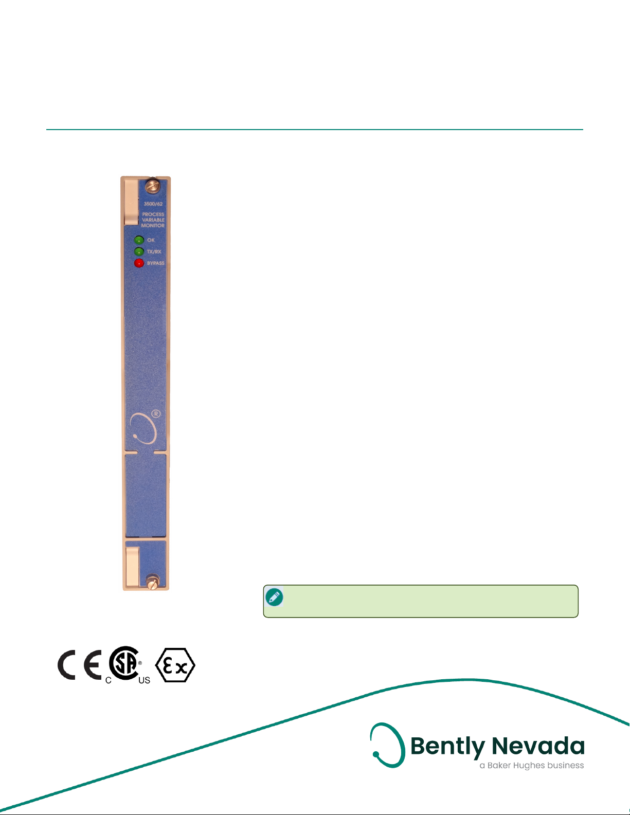
3500/62 Process Variable Monitor
Datasheet
Bently Nevada Machinery Condition Monitoring
Description
The 3500/62 Process Variable Monitor is a 6-channel monitor
for processing machine critical parameters that merit
continuous monitoring, such as pressures, flows,
temperatures, and levels. The monitor accepts +4 to +20 mA
current inputs or any proportional voltage inputs between -10
Vdc and +10 Vdc. It conditions these signals and compares
the conditioned signals to user-programmable alarm
setpoints.
The 3500/62 monitor:
l Continuously compares monitored parameters
against configured alarm setpoints to drive alarms for
machinery protection.
l Provides essential machine information for both
operations and maintenance personnel.
141541 Rev. K
You can program the 3500/62 using the 3500 Rack
Configuration Software to perform either current or voltage
measurements. The 3500/62 offers I/O modules for three
signal input scenarios: +/-10 Volts DC, isolated 4-20 mA, or 420 mA with Intrinsically Safe zener barriers. The Internal Barrier
I/O provides external power input terminals to provide
intrinsically safe power to the 4-20 mA transducers
When used in a Triple Modular Redundant (TMR)
configuration, you must install Process Variable Monitors
adjacent to each other in groups of three. When used in this
configuration, the monitor employs two types of voting to
ensure accurate operation and to avoid loss of machinery
protection due to single-point failures.
Triple Modular Redundant (TMR)Units are no longer
available for purchase.
Page 2

3500/62 Process Variable Monitor
Datasheet 141541 Rev. K
Alarms
Specifications
Inputs
Signal
+/-10 Vdc I/O -10 Vdc to +10 Vdc
4-20 mA Barrier I/O 4-20 mA DC
4-20 mA Isolated I/O 4-20 mA DC.
Voltage Compliance
(4-20 mA Barrier I/O 420mA out)
Isolation
(4-20 mA ISO I/O only)
Input Impedance
+/-10V I/O 1 MΩ
4-20 mA Barrier I/O 50 Ω
4-20 mA Isolated I/O 50 Ω
Power Consumption 7.0 watts, typical.
External transducer
Power (Internal Barrier
I/O Only)
Outputs
Front Panel LEDs
OK LED
TX/RX LED
Bypass LED
Indicates when the Process Variable
Monitor is operating properly.
Indicates when the Process Variable
Monitor is communicating with other
modules in the 3500 rack.
Indicates when the Process Variable
is in Bypass Mode.
13.66 V
500 volts
+24 Vdc. +/- 5% @ 250 mA
max. Fused
Alarm Setpoints
User can set Alert and Danger setpoints for the
value measured by the monitor. Alarms are
adjustable and can normally be set from 0 to
100% of full-scale for each measured value. The
exception is when the full-scale range exceeds
the range of the sensor in which case the
setpoint will be limited to the range of the
sensor. Accuracy of alarms is to within 0.13% of
the desired value. The Process Variable Monitor
has both under and over alarm setpoints.
Alarm Time Delays
User can use software to set alarm delays as
follows:
Alert
Danger
Number of
Active
Channels
0 270
1 360
2 450
3 540
4 630
5 720
6 810
From 1 to 60 seconds in 1 second
intervals.
From 1 to 60 seconds in 0.5 second
intervals or to the minimum alarm
time delay.
Minimum Time Delay (ms)
Signal Conditioning
Specified at +25 °C (+77 °F). Full-scale range for
each channel is set in the field via 3500
Configuration Software. No calibration is
required.
Accuracy
Full Scale
Range
Within ±0.33% of full-scale typical,
±1% maximum.
Maximum 20,000 units mapped over
the input signal span. Minimum
input signal span for voltage input is
2 volts.
You can also set the Danger time delay at a
millisecond interval that varies from 270 to 810
milliseconds, depending on the number of active
channels. The millisecond danger interval is
determined as follows:
270ms minimum time + (90ms x number of active
channels)
As more channels are used, the alarm time delay
increases. The configuration software will
indicate the minimum alarm time delay based
on the channel loading.
2/8
Page 3

3500/62 Process Variable Monitor
Datasheet 141541 Rev. K
Proportional Values
Proportional values are Process Variable
measurements used to monitor the machine.
The Process Variable Monitor returns current or
voltage proportional values in a variety of
different units that are configurable.
Environmental Limits
Operating
Temperature
Operating
Temperature
Storage
Temperature
Humidity 95%, noncondensing.
-30°C to +65°C (-22°F to +149°F)
when used with Internal/External
Termination I/O Module.
0°C to +65°C (+32°F to +149°F) when
used with Internal Barrier I/O Module
(Internal Termination).
40°C to +85°C
(-40°F to +185°F).
Monitor Module
Dimensions
(height x
width x
depth)
Weight 0.82 kg (1.8 lbm)
I/O Modules (without barriers)
Dimensions
(height x
width x
depth)
Weight: 0.20 kg (0.44 lbm)
I/O Module (with barriers)
Dimensions
(height x
width x
depth)
Weight 0.46 kg (1.01 lbm)
241.3 mm x 24.4 mm x 241.8 mm
9.50 in x 0.96 in x 9.52 in)
241.3 mm x 24.4 mm x 99.1 mm
(9.50 in x 0.96 in x 3.90 in)
241.3 mm x 24.4 mm x 99.1 mm
(9.50 in x 0.96 in x 3.90 in)
Rack Space Requirements
Monitor
Module
I/O Modules 1 full-height rear slot.
1 full-height front slot.
3/8
Page 4

3500/62 Process Variable Monitor
Datasheet 141541 Rev. K
Compliance and Certifications
FCC
This device complies with part 15 of the
FCC Rules. Operation is subject to the
following two conditions:
l This device may not cause harmful
interference.
l This device must accept any
interference received, including
interference that may cause
undesired operation.
EMC
European Community Directive:
EMC Directive 2014/30/EU
Standards:
EN 61000-6-2 Immunity for
Industrial Environments
EN 61000-6-4 Emissions for
Industrial Environments
Hazardous Area Approvals
For the detailed listing of country and product
specific approvals, refer to the Approvals Quick
Reference Guide (108M1756) available from
Bently.com.
CSA/NRTL/C
Class I, Zone 2: AEx/Ex nA nC ic
IIC T4 Gc;
When used with
I/O module
ordering options
without internal
barriers
When used with
I/O module
ordering options
with internal
barriers
Class I, Zone 2: AEx/Ex ec nC ic
IIC T4 Gc;
Class I, Division 2, Groups A, B, C,
and D;
T4 @ Ta= -20˚C to +65˚C (-4˚F
to +149˚F)
When installed per drawing
149243 or 149244.
Class I, Zone 2: AEx/Ex nA nC ic
[ia Ga] IIC T4 Gc;
Class I, Zone 2: AEx/Ex ec nC ic
[ia Ga] IIC T4 Gc;
Class I, Division 2, Groups A, B, C,
and D (W/ IS Output for Division
1)
T4 @ Ta= -20˚C to +65˚C (-4˚F
to +149˚F)
When installed per drawing
138547.
Electrical Safety
European Community Directive:
LV Directive 2014/35/EU
Standards:
EN 61010-1
RoHS
European Community Directive:
RoHS Directive 2011/65/EU
Maritime
ABS - Marine and Offshore Applications
DNV GL Rules for Classification – Ships,
Offshore Units, and High Speed and Light
Craft
ATEX/IECEx
When used with
I/O module
ordering options
without internal
barriers
When used with
I/O module
ordering options
with internal
barriers
II 3 G
Ex nA nC ic IIC T4 Gc;
Ex ec nC ic IIC T4 Gc;
T4 @ Ta= -20˚C to +65˚C (-4˚F
to +149˚F)
When installed per drawing
149243 or 149244.
II 3(1) G
Ex nA nC ic [ia Ga] IIC T4 Gc;
Ex ec nC ic [ia Ga] IIC T4 Gc;
T4 @ Ta= -20˚C to +65˚C (-4˚F
to +149˚F)
When installed per drawing
138547.
4/8
Page 5

3500/62 Process Variable Monitor
Datasheet 141541 Rev. K
Ordering Considerations
General
If the 3500/62 Module is added to an existing
3500 Monitoring System, the monitor requires
the following (or later) firmware and software
versions:
l 3500/20 Module Firmware – 1.07 (Rev G)
l 3500/01 Software – Version 2.20
l 3500/02 Software – Version 2.10
l 3500/03 Software – Version 1.20
If the Internal Barrier I/O is used the system
must also meet these requirements:
l 3500/62 Module Firmware- 1.06 (Rev C)
l 3500/01 Software – Version 2.30
You cannot use External Termination
Blocks with Internal Termination I/O
modules.
When ordering I/O Modules with External
Terminations, you must order the External
Termination Blocks and Cables separately.
Internal Barrier I/O Module
Consult the 3500 Internal Barrier
Important
info
Fuse 250 mA, 250 V fast blow type.
specification sheet (part number
141495-01) if you select the Internal
Barrier Option.
5/8
Page 6

3500/62 Process Variable Monitor
Datasheet 141541 Rev. K
Ordering Information
For the detailed listing of country and product
specific approvals, refer to the Approvals Quick
Reference Guide (108M1756) available from
Bently.com.
Process Variable Monitor
3500/62-AA-BB
A: I/O Module Type
01
02
03
04
05
B: Agency Approval Option
00 None
01 CSA/NRTL/C
02 ATEX/CSA (Class 1, Zone 2)
-10 to +10 Vdc I/O Module with Internal
Terminations
-10 to +10 Vdc I/O Module with External
Terminations
Isolated +4 to +20 mA I/O Module with
Internal Terminations
Isolated +4 to +20 mA I/O Module with
External Terminations
Non-Isolated +4 to +20 mA I/O Module with
Internal Barriers and Internal Terminations
Agency Approval Option B 02 is available
only with Ordering Options A 01 and A 05.
External Termination Blocks
136595-01
136603-01
3500/62 External Termination Block
(Terminal Strip Connectors).
3500/62 External Termination Block
(Euro Style Connectors).
Cables
3500/62 Transducer (XDCR) Signal
to External Termination (ET) Block
Cable
134544-AAAA-BB
A: Cable Length
0005 5 feet (1.5 metres)
0007 7 feet (2.1 metres)
0010 10 feet (3 metres)
0025 25 feet (7.5 metres)
0050 50 feet (15 metres)
0100 100 feet (30.5 metres)
B: Assembly Instructions
01 Not assembled
02 Assembled
Spares
Part Number Description
163179-03 3500/62 monitor
136590-01 Firmware IC
04425545 Grounding wrist strap (single use)
04400037 IC removal tool
136491-01
136499-01
136294-01
136483-01
137110-01
136973 3500/62 User Guide
01700059 Replacement fuse for barrier I/O
-10 Vdc to +10 Vdc I/O Module with
internal terminations
-10 Vdc to +10 Vdc I/O Module with
external terminations
Isolated +4 to +20 mA I/O Module
with internal terminations
Isolated +4 to +20 mA I/O Module
with external terminations
4 to 20 mA Barrier I/O Module with
internal terminations
6/8
Page 7

3500/62 Process Variable Monitor
Datasheet 141541 Rev. K
Graphs and Figures
1. Status LEDs
2. Main Module Front View
3. 4 to 20mA Internal Terminations I/O Module
4. –10 to +10 Vdc Internal Terminations I/O Module
5. 4 to 20mA External Terminations I/O Module
6. -10 to +10 Vdc External Terminations I/O Module
Figure 1: Front and Rear Views of the 3500/62 Process Variable Monitor
7/8
Page 8

3500/62 Process Variable Monitor
Datasheet 141541 Rev. K
Copyright 2020 Baker Hughes Company. All rights reserved.
Bently Nevada and Orbit Logo are registered trademarks of Bently Nevada, a Baker Hughes Business, in the United
States and other countries. The Baker Hughes logo is a trademark of Baker Hughes Company. All other product and
company names are trademarks of their respective holders. Use of the trademarks does not imply any affiliation
with or endorsement by the respective holders.
Baker Hughes provides this information on an “as is” basis for general information purposes. Baker Hughes does
not make any representation as to the accuracy or completeness of the information and makes no warranties of
any kind, specific, implied or oral, to the fullest extent permissible by law, including those of merchantability and
fitness for a particular purpose or use. Baker Hughes hereby disclaims any and all liability for any direct, indirect,
consequential or special damages, claims for lost profits, or third party claims arising from the use of the
information, whether a claim is asserted in contract, tort, or otherwise. Baker Hughes reserves the right to make
changes in specifications and features shown herein, or discontinue the product described at any time without
notice or obligation. Contact your Baker Hughes representative for the most current information.
The information contained in this document is the property of BakerHughes and its affiliates; and is subject to
change without prior notice. It is being supplied as a service to our customers and may not be altered or its content
repackaged without the express written consent of Baker Hughes. This product or associated products may be
covered by one or more patents. See Bently.com/legal.
1631 Bently Parkway South, Minden, Nevada USA 89423
Phone: 1.775.782.3611 or 1.800.227.5514 (US only)
Bently.com
8/8
 Loading...