

Page 1
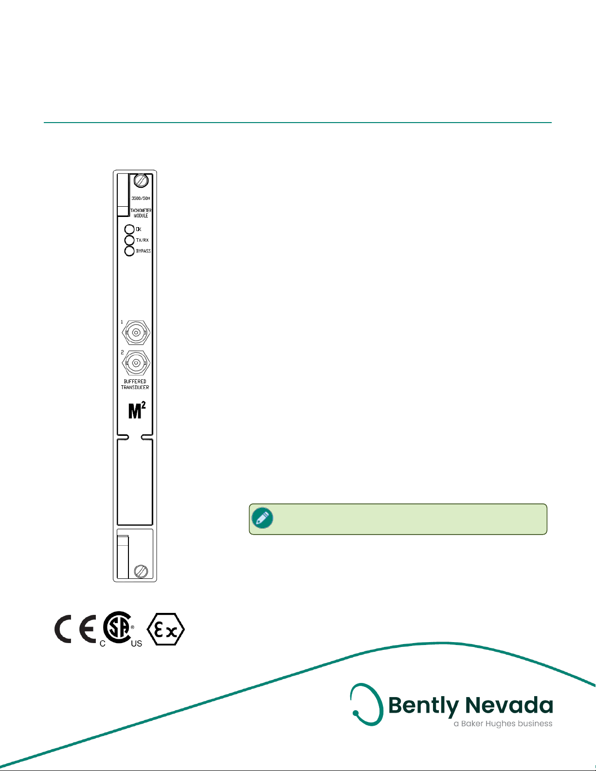
3500/50M Tachometer Module
Datasheet
Bently Nevada Machinery Condition Monitoring
Description
The 3500/50M Tachometer Module is a 2-channel module that accepts
input from proximity probes or magnetic pickups to determine shaft
rotative speed, rotor acceleration, or rotor direction. The module
compares these measurements against user-programmable alarm
setpoints and generates alarms when the setpoints are violated.
The Tachometer Module is programmed using the 3500 Rack
Configuration software. The following configuration options are
available:
l Speed Monitoring, Setpoint Alarming and Speed Band Alarming
l Speed Monitoring, Setpoint Alarming and Zero Speed
Notification
l Speed Monitoring, Setpoint Alarming and Rotor Acceleration
Alarming
l Speed Monitoring, Setpoint Alarming and Reverse Rotation
Notification
141538 Rev. P
The 3500/50M Tachometer Module can be configured to supply
conditioned Keyphasor signals to the backplane of the 3500 rack for use
by other monitors. Therefore, you don't need a separate Keyphasor
module in the rack.
The 3500/50M Tachometer Module has a peak hold feature that stores
the highest speed, the highest reverse speed, or the number of reverse
rotations that the machine has reached. You can reset the peak values.
Bently Nevada offers an Overspeed Protection System
(Product 3701/55).
Page 2
3500/50M Tachometer Module
Datasheet 141538 Rev. P
WARNING
PRODUCT MISUSE
Risk of personal injury or equipment damage.
Do not use the 3500/50M Tachometer Module
independently or as a component of a speed control or an
overspeed protection system because it does not provide
protective redundancy or the response speed needed for
reliable operation as a speed control or overspeed
protection system.
The analog proportional output is suitable for data logging,
chart recording, or display purposes only. Speed alert
setpoints are suitable for annunciation purposes only.
Magnetic Pickups:
Do not use magnetic pickups for the reverse rotation option
or zero speed option. Otherwise, false indications of
rotation direction may occur. The transducers do not
provide a clean edge for the detection circuit during low
speeds.
2/12
Page 3

3500/50M Tachometer Module
Datasheet 141538 Rev. P
module via Euro style connectors.
Specifications
Inputs
Signal
Input signal range
Input impedance 20 k Ω (standard)
Power
consumption
Transducers
Each 3500/50M Tachometer
Module accepts up to two
transducer signals from proximity
probe transducers or magnetic
pickups.
+10.0 V to -24.0 V
Signals exceeding this range are
limited internally by the module.
40 k Ω (TMR)
7.15 k Ω (Internal Barrier)
5.8 watts, typical
Accepts 1 to 2 proximity
transducer signals
Restrictions may apply to
magnetic pickups. See on
page 2.
Output
Impedance
Transducer
Power
Supply
Recorder
Voltage
Compliance
(current
output)
Resolution
550 Ω
24 Vdc, 40 mA maximum per channel
+4 to +20 mA
Values are proportional to module fullscale range (rpm or rpm/min).
Individual recorder values are provided
for each channel.
Monitor operation is unaffected by
short circuits on recorder outputs.
0 to +12 Vdc range across load
Load resistance is 0 to 600 Ω
0.3662 µA per bit ±0.25% error at room
temperature ±0.7% error over
temperature range
Outputs
Front Panel LEDs
OK LED Indicates when the 3500/50M
Tachometer Module is operating
properly.
TX/RX
LED
Bypass
LED
Buffered Transducer
Outputs
Indicates when the Tachometer Module
is communicating with other modules in
the 3500 rack.
Indicates when the Tachometer Module
is in Bypass Mode.
The front of each module has one
coaxial connector for each channel.
Each connector is short circuit and ESD
protected.
Buffered outputs are available at the I/O
Update rate approximately 100 ms
Signal Conditioning
Specified at +25 ºC (+77 ºF)
Speed Input
The 3500/50M Tachometer
Module supports 1 to 255 events
per revolution for Rotor
Acceleration and Zero Speed
channel types.
All other channel types support
0.0039 to 255 events per
revolution.
All channel types support a
maximum full scale range of
99,999 rpm and a maximum input
frequency of 20 kHz.
Minimum input frequency for
3/12
Page 4

3500/50M Tachometer Module
Datasheet 141538 Rev. P
proximity transducers is 0.0167
Hz (1 rpm for 1 event per
revolution).
Minimum input frequency for
passive magnetic pickups is 3.3
Hz.
RPM Accuracy Less than 100 rpm = ± 0.1 rpm
100 to 10,000 rpm = ±1 rpm
10,000 to 99,999 rpm = ± 0.01%
of true shaft speed
RPM/Min
Accuracy
± 20 rpm/min
Transducer Conditioning
Auto Threshold
Manual Threshold
Hysteresis User selectable from 0.2 to 2.5
Use for any input above 0.0167
Hz
(1 rpm for 1 event/revolution)
Minimum signal amplitude for
triggering is 1 volt peak-to-peak.
User selectable from +9.5 Vdc to
-23.5 Vdc
Minimum signal amplitude for
triggering is 500 millivolts peakto-peak
volts
Alarms
Alarm Setpoints
Alarm 1 levels (setpoints) can be
set for each value measured by
the Tachometer.
Alarm 2 setpoints can be set for
any two of the values measured
by the Tachometer.
Alarm setpoints are set using
software configuration.
Alarms are adjustable and can
normally be set from 0 to 100% of
full scale for each measured
value.
Alarm Time
Delays
Alarm 1 Time
Delay
Alarm 2 Time
Delay
Programmable alarm delays for
Alarm 1 and Alarm 2
From 1 to 60 seconds in 1 second
intervals
From 1 to 60 seconds in 0.1
second intervals
Measured Values
Measured values are speed measurements used to
monitor a machine. The 3500/50M Tachometer Module
returns the following measured values:
1
Rotor Speed
Speed
Speed Band
4/12
Page 5

3500/50M Tachometer Module
Datasheet 141538 Rev. P
Peak Speed
Rotor Speed 2 Speed
2
Gap
2
1
Speed Band
2
2
Rotor
Acceleration
Rotor
Acceleration 2
Peak Speed
Rotor Acceleration
Speed
Peak Speed
Rotor Acceleration
2
Gap
Speed
Peak Speed
Zero Speed Zero Speed
2
1
Speed
Peak Speed
Zero Speed 2 Zero Speed
2
Gap
2
1
Speed
Peak Speed
2
Reverse Rotation Reverse Speed
Reverse Peak Speed
Speed (forward)
2
Gap
Num Reverse Rotations
Weight 0.20 kg (0.44 lb)
I/O Modules (internal barrier)
Dimensions
(Height x Width x
Depth)
1
241.3 mm x 24.4 mm x 163.1
mm
(9.50 in x 0.96 in x 6.42 in)
Weight 0.46 kg (1.01 lb)
Rack Space Requirements
1
Monitor Module 1 full-height front slot
I/O Modules 1 full-height rear slot
1
1
The primary value for the channel. This value
can be included in contiguous registers in the
Communications Gateway Module.
2
This measured value is for display and setup
purposes only. No alarms are provided.
Physical
Monitor Module (Main Board)
Dimensions
(Height x Width x
Depth)
Weight
I/O Modules (non-barrier)
Dimensions
(Height x Width x
Depth)
241.3 mm x 24.4 mm x 241.8
mm
(9.50 in x 0.96 in x 9.52 in)
0.82 kg (1.8 lb)
241.3 mm x 24.4 mm x 99.1
mm
(9.50 in x 0.96 in x 3.90 in)
5/12
Page 6

3500/50M Tachometer Module
Datasheet 141538 Rev. P
Compliance and Certifications
FCC
This device complies with part 15 of the FCC
Rules. Operation is subject to the following two
conditions:
l This device may not cause harmful
interference.
l This device must accept any interference
received, including interference that may
cause undesired operation.
EMC
European Community Directive:
EMC Directive 2014/30/EU
Standards:
EN 61000-6-2 Immunity for Industrial
Environments
EN 61000-6-4 Emissions for Industrial
Environments
Electrical Safety
European Community Directive:
LV Directive 2014/35/EU
Standards:
EN 61010-1
Hazardous Area Approvals
For the detailed listing of country and product
specific approvals, refer to the
Quick Reference Guide
from Bently.com.
CSA/NRTL/C
When used with
I/O module
ordering options
without internal
barriers
When used with
I/O module
ordering options
with internal
barriers
(108M1756) available
Class I, Zone 2: AEx/Ex nA nC
ic IIC T4 Gc;
Class I, Zone 2: AEx/Ex ec nC
ic IIC T4 Gc;
Class I, Division 2, Groups A,
B, C, and D;
T4 @ Ta= -20˚C to +65˚C (-4˚F
to +149˚F)
When installed per drawing
149243 or 149244.
Class I, Zone 2: AEx/Ex nA nC
ic [ia Ga] IIC T4 Gc;
Class I, Zone 2: AEx/Ex ec nC
ic [ia Ga] IIC T4 Gc;
Class I, Division 2, Groups A,
B, C, and D (W/ IS Output for
Division 1)
T4 @ Ta= -20˚C to +65˚C (-4˚F
to +149˚F)
When installed per drawing
138547.
Approvals
RoHS
European Community Directive:
RoHS Directive 2011/65/EU
Maritime
ABS - Marine and Offshore Applications
DNV GL Rules for Classification – Ships,
Offshore Units, and High Speed and Light Craft
6/12
Page 7

3500/50M Tachometer Module
Datasheet 141538 Rev. P
ATEX/IECEx
When used with
I/O module
ordering options
without internal
barriers
When used with
I/O module
ordering options
with internal
barriers
II 3 G
Ex nA nC ic IIC T4 Gc;
Ex ec nC ic IIC T4 Gc;
T4 @ Ta= -20˚C to +65˚C (-4˚F
to +149˚F)
When installed per drawing
149243 or 149244.
II 3(1) G
Ex nA nC ic [ia Ga] IIC T4 Gc;
Ex ec nC ic [ia Ga] IIC T4 Gc;
T4 @ Ta= -20˚C to +65˚C (-4˚F
to +149˚F)
When installed per drawing
138547.
7/12
Page 8

3500/50M Tachometer Module
Datasheet 141538 Rev. P
Ordering Considerations
To add the 3500/50M Tachometer Module to an existing
3500 Monitoring System, you must have the following
versions of firmware and software:
Firmware and Software Version
3500/22M Module Firmware
3500/01 Configuration Software Version 4.20 or
3500/02 Data Acquisition
Software
3500/03 Display Software
3500/50M Firmware Revision 5.30 or
3500/50M
Consider the following guidelines and restrictions
before placing an order:
l External Termination Blocks cannot be used
with Internal Termination I/O modules.
l When ordering I/O Modules with External
Terminations, you must order External
Termination Blocks and cables separately.
l Use Bussed External Termination Blocks with
TMR I/O modules only.
l Before selecting the Internal Barrier option, see
3500 Internal Barriers product datasheet
(document 141495).
Revision (1.70)
later
Version 2.52 or
later
Version 1.52 or
later
later
Not
compatible
with any version of
3500/20
8/12
Page 9

3500/50M Tachometer Module
Datasheet 141538 Rev. P
Ordering Information
For the detailed listing of country and product
specific approvals, refer to the
Quick Reference Guide
from Bently.com.
(108M1756) available
3500/50M Tachometer Module
3500/50-AA-BB
A: I/O Module Type
01
02 I/O Module with External Terminations
04 I/O Module with Internal Barriers and Internal
B: Hazardous Area Approval Option
00 None
01
I/O Module with Internal Terminations
Terminations
CSA/NRTL/C (Class 1, Division 2)
Approvals
0005
0007 7 feet (2.1 metres)
0010 10 feet (3.0 metres)
0025 25 feet (7.6 metres)
0050 50 feet (15.2 metres)
0100
B: Assembly Instructions
01
02 Assembled
5 feet (1.5 metres)
100 feet (30.5 metres)
Not Assembled
3500 Recorder Output to ET Block Cable
129529-AAAA-BB
A: I/O Cable Length
0005
0007 7 feet (2.1 metres)
5 feet (1.5 metres)
02
ATEX/IECEx/CSA (Class 1, Zone 2)
External Termination (ET) Blocks
Part Number Description
125808-05 Tachometer ET Block
Euro Style connectors
128015-05 Tachometer ET Block
Terminal Strip connectors
128702-01 Recorder ET Block
Euro Style connectors
128710-01 Recorder ET Block
Terminal Strip connectors
Cables
3500 Tachometer Signal to ET Block Cable
135101-AAAA-BB
A: I/O Cable Length
0010 10 feet (3.0 metres)
0025 25 feet (7.6 metres)
0050 50 feet (15.2 metres)
0100
B: Assembly Instructions
01 Not Assembled
02
100 feet (30.5 metres)
Assembled
9/12
Page 10

3500/50M Tachometer Module
Datasheet 141538 Rev. P
Spares
Part Number Description
288062-02 3500/50M Tachometer Module
133442-01 I/O Module with Internal
Terminations
136703-01 Discrete Internal Barrier I/O
Module with Internal
Terminations
133434-01 I/O Module with External
Terminations
133450-01 TMR I/O Module with External
Terminations
134938 3500/50M Tachometer User
Guide
04425545 Grounding Wrist Strap
Single use only
00580434 Connector Header
Internal Termination
8-position|
Green
00580436 Connector Header
Internal Termination
6-position
Green
00502133 Connector Header
Internal Termination
12-position
Blue
10/12
Page 11

3500/50M Tachometer Module
Datasheet 141538 Rev. P
Graphs and Figures
1. Status LEDs
2. Buffered transducer outputs
3. I/O Module, Internal Terminations
4. I/O Module, External Terminations
5. I/O Module, TMR, External Terminations
6. I/O Module, Internal Barrier, Internal Terminations
Figure 1: Front and Rear Views of the 3500/50M Tachometer Module
11/12
Page 12

3500/50M Tachometer Module
Datasheet 141538 Rev. P
Copyright 2020 Baker Hughes Company. All rights reserved.
Bently Nevada, Orbit Logo and Keyphasor are registered trademarks of Bently Nevada, a Baker Hughes Business, in the
United States and other countries. The Baker Hughes logo is a trademark of Baker Hughes Company. All other product and
company names are trademarks of their respective holders. Use of the trademarks does not imply any affiliation with or
endorsement by the respective holders.
Baker Hughes provides this information on an “as is” basis for general information purposes. Baker Hughes does not make
any representation as to the accuracy or completeness of the information and makes no warranties of any kind, specific,
implied or oral, to the fullest extent permissible by law, including those of merchantability and fitness for a particular purpose
or use. Baker Hughes hereby disclaims any and all liability for any direct, indirect, consequential or special damages, claims
for lost profits, or third party claims arising from the use of the information, whether a claim is asserted in contract, tort, or
otherwise. Baker Hughes reserves the right to make changes in specifications and features shown herein, or discontinue the
product described at any time without notice or obligation. Contact your Baker Hughes representative for the most current
information.
The information contained in this document is the property of Baker Hughes and its affiliates; and is subject to change without
prior notice. It is being supplied as a service to our customers and may not be altered or its content repackaged without the
express written consent of Baker Hughes. This product or associated products may be covered by one or more patents. See
Bently.com/legal.
1631 Bently Parkway South, Minden, Nevada USA 89423
Phone: 1.775.782.3611 or 1.800.227.5514 (US only)
Bently.com
12/12
 Loading...