

Page 1
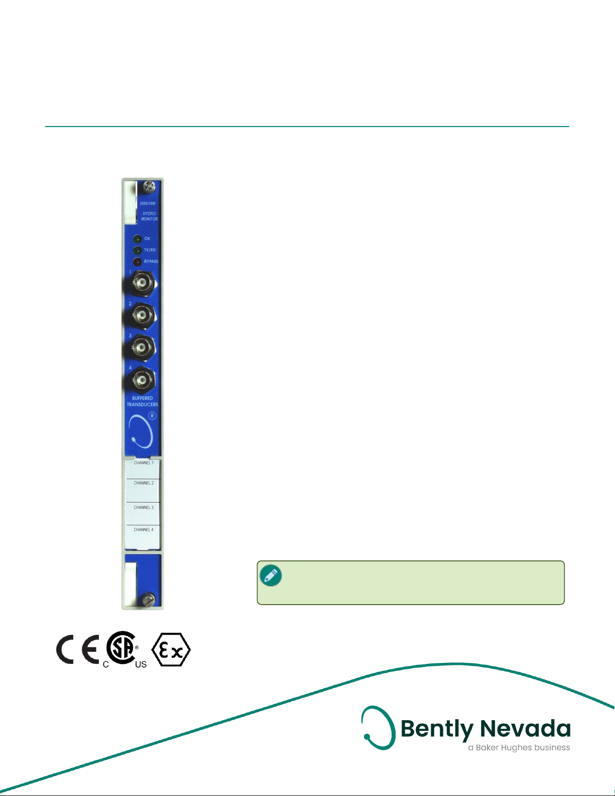
3500/46M Hydro Monitor
Datasheet
Bently Nevada Machinery Condition Monitoring
Description
The 3500/46M Hydro Monitor is a four-channel instrument
that accepts input from proximity, seismic, dynamic pressure
and air gap sensors. The monitor conditions the signal to
provide vibration, position and both static and dynamic
pressure measurements. It then compares the conditioned
signals with user-programmable alarms. Hydro Radial
Vibration channels combine the shaft gap movement with
the NX amplitude to provide a measurement to alarm on
shear-pin failure.
Using the 3500 Rack Configuration Software, you can
configure the 3500/46M Hydro Monitor to perform the
following functions:
l Hydro Radial Vibration
l Hydro Air Gap
l Hydro Velocity
l Hydro Acceleration
l Hydro Thrust
l Multimode Hydro RV
l Multimode Air Gap
l Multimode Hydro Velocity
l Multimode Thrust
l Multimode Acceleration
l Multimode Hydro Dynamic Pressure
l Hydro Stator End Winding (SEW)
144408 Rev. Y
The monitor channels are programmed in pairs. Each
channel may have separate or identical
configurations.
Page 2

3500/46M Hydro Monitor
Datasheet 144408 Rev. Y
The primary purpose of the 3500/46M Hydro
Monitor is to provide the following:
l Machinery protection by continuously
comparing monitored parameters
against configured alarm setpoints to
drive alarms
l Essential machine information for
operations and maintenance personnel
Hydro Velocity channels provide early
warning of pending machinery
problems and assist in diagnosing
them. Due to the nature of high
amplitude, low frequency velocity
events, the Hydro Velocity channel type
cannot be used for automated
machinery protection.
Each channel, depending on configuration,
typically conditions its input signal to generate
various parameters called static values. You
can configure alert setpoints for each active
static value and danger setpoints for any two
of the active static values.
You can configure multimode channels to
have up to eight sets of alarm parameters
including alert and danger set points and
alarm time delays. Each set may be configured
for a specific machine mode.
As the machine changes modes, the monitor
can switch to a specific set using contacts on
multimode I/O modules or software
commands through a communications
gateway.
2/16
Page 3

3500/46M Hydro Monitor
Datasheet 144408 Rev. Y
Hydro SEW 10.19 mV/m/s2 (100 mV/g)
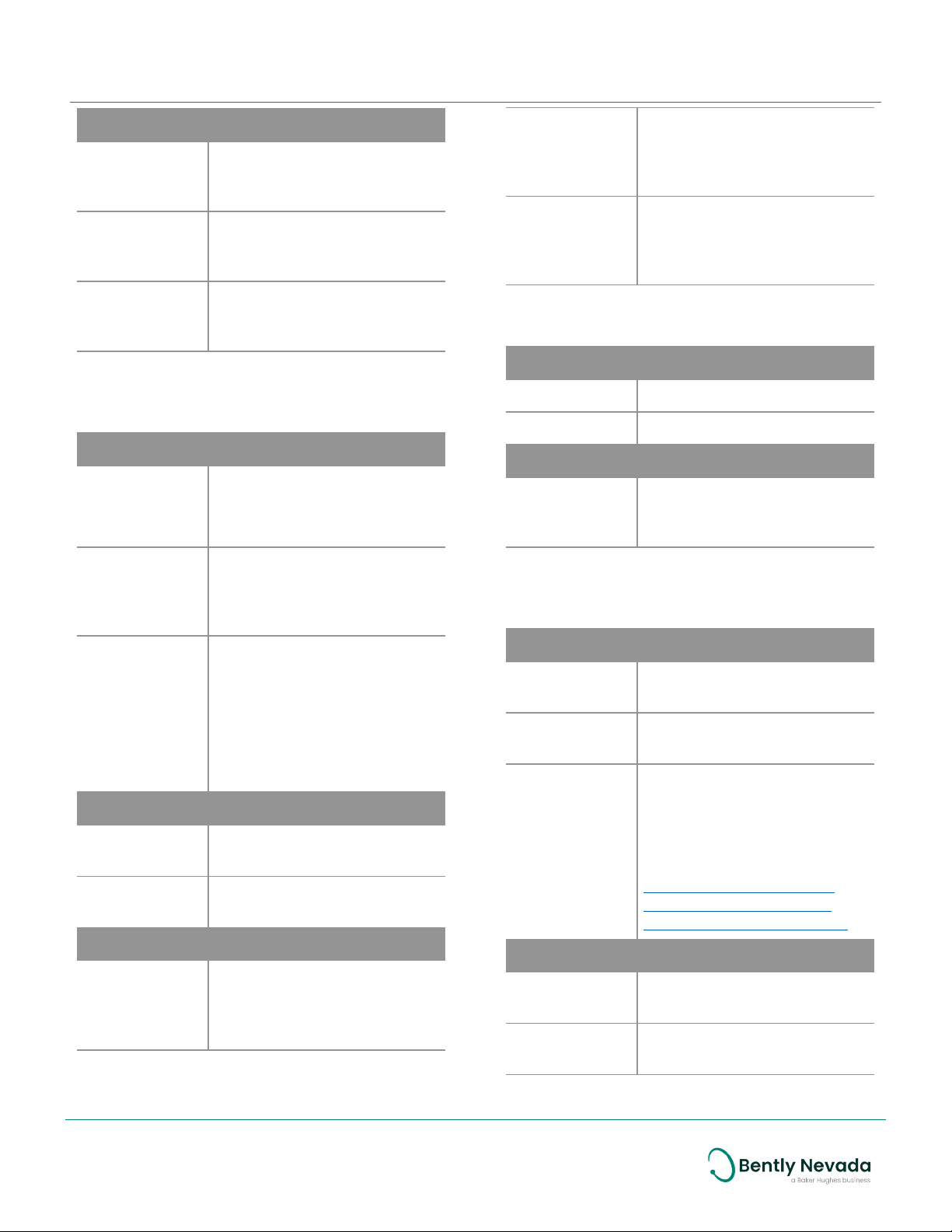
Specifications
Inputs
Signal
Accepts 1 to 4 proximity, air
gap, velocity or acceleration
sensor signals
Multimode
Hydro
Dynamic
Pressure
Outputs
Refer to the Bently Nevada
350300 Dynamic Pressure
Sensor datasheet, document
110M4613
Power
consumption
Multimode
positive input
I/O
Input Impedance
Prox/Velom
I/O and
Multimode
Prox/Velom
I/O
Sensitivity
Hydro Radial
Vibration
and
Multimode
Hydro RV
Hydro Air
Gap and
Multimode
Air Gap
Hydro
Velocity and
Multimode
Hydro
Velocity
Hydro
Thrust and
Multimode
Thrust
Hydro
Acceleration
and
Multimode
Acceleration
0.79 mV/μm (20 mV/mil),
3.94 mV/μm (100 mV/mil) or
7.87 mV/μm (200 mV/mil)
0.20 mV/μm (5 mV/mil),
0.22 mV/μm (5.6 mV/mil),
0.49 mV/μm (12.5 mV/mil) or
0.55 mV/μm (14 mV/mil)
20 mV/mm/s (508 mV/in/s)
3.94 mV/μm (100 mV/mil),
7.87 mV/μm (200 mV/mil) or
11.22 mV/μm (285 mV/mil)
1.02 mV/m/s2 (10 mV/g) or
2.55 mV/m/s2 (25 mV/g)
7.7 watts, typical
50 kΩ
10 kΩ for Prox/Accel
3.5 MΩ for Velomitor
Front Panel LEDs
OK LED Indicates when the 3500/46M Hydro
Monitoris operating properly
TX/RX
LED
Bypass
LED
Buffered
Transducer
Outputs
Output
Impedance
Transducer Power Supply
Prox/Velom
I/O and
Multimode
Prox/Velom
I/O
Multimode
Positive
Input I/O
Recorder
Indicates when the 3500/46M Hydro
Monitor is communicating with
other modules in the 3500 Rack.
Indicates when the 3500/46M Hydro
Monitor is in Bypass Mode.
The front of each monitor has
one coaxial connector for each
channel.
Each connector is short-circuit
protected.
550 Ω
-23 Vdc nominal at 43 mA max
+23 Vdc nominal at 23 mA max
+4 to +20 mA. Output is
proportional to monitor fullscale.
One output is provided for each
channel.
3/16
Page 4

3500/46M Hydro Monitor
Datasheet 144408 Rev. Y
Monitor operation is unaffected
by short circuits on recorder
outputs.
Voltage
Compliance
(current
output)
Resolution
0 to +12 Vdc range across load
Load resistance is 0 to 600 Ω.
0.3662 µA per bit
±0.25% error at room
temperature
±0.7% error over temperature
range
Update rate 100 ms or less
Signal Conditioning
Specified at +25 ºC (+77 ºF) unless
otherwise noted.
Hydro and Multimode Hydro Radial
Vibration
Frequency Response
Direct filter
Gap filter -3 dB at 0.05 Hz
0.104 Hz to 500 Hz
Rotor speed is 25 to 1,500 cpm.
Composite NX amplitude multiplied by the
percent change in gap from its
zero position
Specific for detecting Shear Pin
failure
Accuracy
Direct and
Gap
1X and NX Within ±0.33% of full-scale
Not 1X ±1% of full-scale typical
Composite ±1% of full-scale typical
Within ±0.33% of full-scale
typical
±1% maximum
typical
±1% 1X maximum
±3% NX maximum
±3% maximum
Hydro Air Gap and Multimode Air Gap
Instantaneous
Air Gap
Average Air
Gap
Provides instantaneous gap
measurements when the
pole-passing rate slows to
less than one pole/second
The monitor measures each
pole gap and averages the
values for all poles together
over one revolution.
Not 1X filter 0.25 to 128 times rotor speed
Constant Q notch filter
Minimum rejection in
stopband of -50 dB
1X and NX
vector filter
Constant Q Filter
Minimum rejection in
stopband of –50 dB
The N value in NX is selectable
between 2 and 20 (for
machine speeds of 25 cpm to
1,500cpm) or 2 to 50 (for
machine speeds of 25 cpm to
600 cpm).
1X and NX vector, Not 1X and
composite parameters are
valid for machine speeds per
selected NX value range.
Minimum Air
Gap
Maximum Air
Gap
Min Air Gap
Pole Number
Max Air Gap
Pole Number
4/16
The minimum pole gap
value in a revolution
The maximum pole gap
value in a revolution
The pole number detected
with the minimum gap value
in a revolution
The pole number detected
with the maximum gap
value in a revolution
All values except
instantaneous Air Gap are
valid when the poles passing
rate is between 1 and 200
poles/second.
Page 5
3500/46M Hydro Monitor
Datasheet 144408 Rev. Y
Accuracy
Average Air
Gap
Minimum Air
Gap
Maximum Air
Gap
Within ±0.33% of full scale
typical
±1% maximum
Within ±0.33% of full scale
typical
±1% maximum
Within ±0.33% of full scale
typical
±1% maximum
Hydro Velocity and Multimode Hydro
Velocity
Frequency Response
Bias
Direct Low Mode: 0.1875 to 343.75 Hz,
1X and 2X
vector filter
Filter Quality
High-pass 4-pole (80 dB per decade, 24
Low-pass 2-pole (40 dB per decade,
Accuracy
Direct Within ±1% of full-scale
Low-pass filter
Low Mode: -3dB at 0.02 Hz
High Mode: -3dB at 0.07 Hz
-3dB
High Mode: 0. 75 to 1375 Hz, 3dB
Constant Q Filter
Minimum rejection in
stopband of –51 dB
Low Mode: Valid for machine
speeds of 60 to 6,000 cpm
High Mode: Valid for machine
speeds of 60 to 24,600 cpm
dB per octave)
12dB per octave)
typical
±2% maximum
Exclusive of filters
1X Amplitude Within ±1% of full-scale
typical
±2% maximum
Exclusive of filters
2X Amplitude Within ±1% of full-scale
typical
±2% maximum
Exclusive of filters
Hydro Thrust and Multimode Thrust
Frequency Response
Direct filter -3dB at 1.2 Hz
Gap filter -3dB at 0.4 1 Hz
Accuracy
Direct Within ±0.33% of full-scale
typical
±1% maximum
Hydro Acceleration and Multimode
Acceleration
Frequency Response
Bias filter Low-pass filter
-3dB at 0.01 Hz
Not OKfilter Low-pass filter
-3dB at 2400 Hz
1X and 2X
vector filter
Filter Quality
High pass 4-pole (80 dB per decade,
Low pass 4-pole (80 dB per decade,
Constant Q Filter
Minimum rejection in
stopband of –51 dB
Valid for machine speeds of
60 cpm to 60,000 cpm
See Frequency Ranges -
Multimode Acceleration
Channel on the next page.
24dB per octave)
24dB per octave)
5/16
Page 6

3500/46M Hydro Monitor
Datasheet 144408 Rev. Y
Direct Within ±0.33% of full scale
typical
±1% maximum
Exclusive of filters
Direct
Resultant
Pole Pass
Resultant
±1% of full-scale typical
±2% maximum
±2% of full-scale typical
±3% maximum
1X Amplitude Within ±0.33% of full scale
typical
±1% maximum
Exclusive of filters
2X Amplitude Within ±0.33% of full scale
typical
±1% maximum
Exclusive of filters
Hydro Stator End Winding (SEW)
Frequency Response
Direct 5.0 Hz to 800 Hz (-3dB
corners)
Bias voltage DC to 0.05 Hz (-3dB)
Pole Pass
Amplitude
Direct
Resultant
Pole Pass
Resultant
2x line frequency (100 Hz or
120 Hz)
Constant Q filter (Q=20)
Minimum rejection in stop
band of -60 dB
5.0 Hz to 800 Hz (-3dB
corners)
Resultant of both X and Y
axis inputs
2x line frequency (100 Hz or
120 Hz)
Constant Q filter (Q=20)
Minimum rejection in stop
band of -60 dB
Resultant of both X and Y
axis inputs
Multimode Hydro Dynamic Pressure
Frequency Response
Low mode 0.1875 Hz to 343.7500 Hz
High mode 0.75 Hz to 1375.00 Hz
Filter Quality
High pass 4-pole
(80 dB per decade,
24 dB per octave)
Low pass 4-pole
(80 dB per decade,
24 dB per octave)
Accuracy
Peak Direct
amplitud
RMS Direct
amplitude
Static Pressure ±0.87% of Full Scale
±1% of Full Scale
maximum
±2% of Full Scale
maximum
maximum
Frequency Ranges - Multimode
Acceleration Channel
The following table lists the frequency ranges
for the monitor under different options using
the Multimode Acceleration Channel type:
Accuracy
Direct ±1% of Full Scale maximum
Bias voltage ±1% of Full Scale maximum
Pole Pass
Amplitude
±2% of full-scale typical
±3% maximum
Output Type
RMS 10 to 30,000 10 to 20,000
Peak 3 to 30,000 3 to 20,000
6/16
Non-Integrated
(Hz)
Integrated
(Hz)
Page 7

3500/46M Hydro Monitor
Datasheet 144408 Rev. Y
Physical
Monitor Module (Main Board)
Dimensions
(Height x Width x
Depth)
Weight
I/O Modules
Dimensions
(Height x Width x
Depth)
Weight 0.20 kg (0.44 lb)
241.3 mm x 24.4 mm x
241.8 mm
(9.50 in x 0.96 in x 9.52 in)
0.91 kg (2.0 lb)
241.3 mm x 24.4 mm x 99.1
mm
(9.50 in x 0.96 in x 3.90 in)
Rack Space Requirements
Monitor
Module
I/O Modules 1 full-height rear slot
1 full-height front slot
Alarms
Alarm
setpoints
Use Rack Configuration
Software to set alert levels
for each value measured by
the monitor and danger
setpoints for any two of the
values measured by the
monitor.
Alarms are adjustable from
0 to 100% of full-scale for
each measured value
except when the full-scale
range exceeds the range of
the transducer. In this case,
the range of the transducer
will limit the setpoint.
Multimode
Hydro RV
Hydro Air Gap
and Multimode
Air Gap
Hydro Velocity
and Multimode
Hydro Velocity
Hydro Thrust
and Multimode
Thrust
Hydro
Acceleration
and Multimode
Acceleration
Hydro Stator
End Winding
(SEW)
Multimode
Hydro
Dynamic
Pressure
NX Amplitude
Composite
1X Phase Lag
NX Phase Lag
Direct
Gap
Not 1X Amplitude
1X Amplitude
NX Amplitude
Composite
1X Phase Lag
Average Air Gap
Minimum Air Gap
Direct
1X Amplitude
2X Amplitude
1X Phase Lag
2X Phase Lag
Direct
Gap
Direct
1X Amplitude
2X Amplitude
1X Phase Lag
2X Phase Lag
Direct
Pole Pass Amplitude
Direct Resultant
Pole Pass Resultant
Direct
Static Pressure
1X Amplitude
2X Amplitude
1X Phase Lag
2X Phase Lag
Alarm
accuracy
Hydro Radial
Vibration
Within 0.13% of the desired
value
Direct
Gap
Not 1X Amplitude
1X Amplitude
Alarm Time Delays
You can program alarm delays using
Rack Configuration Software.
Alert From 1 to 400 seconds in one
7/16
Page 8

3500/46M Hydro Monitor
Datasheet 144408 Rev. Y
second intervals
Danger From 1 to 400 seconds in one
second intervals
Multimode
channels
Standard
channels
You can set delays for each
measured value that has
alarm set points.
You can set one alert and
danger delay for the
channel.
8/16
Page 9

3500/46M Hydro Monitor
Datasheet 144408 Rev. Y
3500/46M Hydro Monitor Measured
Variables
Measured variables are used to monitor the
machine. The 3500/46M provides the following
measured variables:
Hydro Radial
Vibration
Multimode
Hydro RV
Hydro Air Gap Average Air Gap
Multimode Air
Gap
Direct
Gap
1X Amplitude
1X Phase Lag
NX Amplitude
NX Phase Lag
Not 1X Amplitude
Composite Amplitude
Direct
Gap
1X Amplitude
1X Phase Lag
NX Amplitude
Not 1X Amplitude
Composite Amplitude
Mode
Instantaneous Air Gap
Minimum Air Gap
Maximum Air Gap
Minimum Air Gap Pole
Number
Maximum Air Gap Pole
Number
Average Air Gap
Instantaneous Air Gap
Minimum Air Gap
Maximum Air Gap
Minimum Air Gap Pole
Number
Maximum Air Gap Pole
Number
Mode
Hydro Velocity Bias
1X Amplitude
1X Phase Lag
2X Amplitude
2X Phase Lag
Mode
Hydro Thrust Direct
Gap
Multimode
Thrust
Hydro
Acceleration
Multimode
Acceleration
Hydro Stator
End Winding
(SEW)
Multimode
Hydro
Dynamic
Pressure
Direct
Gap
Mode
Direct
Bias
1X Amplitude
1X Phase Lag
2X Amplitude
2X Phase Lag
Direct
Bias
1X Amplitude
1X Phase Lag
2X Amplitude
2X Phase Lag
Mode
Direct
Bias Voltage
Pole Pass Amplitude
Direct Resultant
Pole Pass Resultant
Direct
Static Pressure
1X Amplitude
1X Phase Lag
2X Amplitude
2X Phase Lag
Mode
Hydro Velocity Direct
Bias
1X Amplitude
1X Phase Lag
2X Amplitude
2X Phase Lag
Multimode Direct
9/16
Page 10

3500/46M Hydro Monitor
Datasheet 144408 Rev. Y
Compliance and Certifications
FCC
This device complies with part 15 of the
FCC Rules. Operation is subject to the
following two conditions:
l This device may not cause harmful
interference.
l This device must accept any
interference received, including
interference that may cause
undesired operation.
EMC
European Community Directive:
EMC Directive 2014/30/EU
Standards:
EN 61000-6-2 Immunity for
Industrial Environments
EN 61000-6-4 Emissions for
Industrial Environments
Electrical Safety
European Community Directive:
LV Directive 2014/35/EU
Hazardous Area Approvals
For the detailed listing of country and
product specific approvals, refer to the
Approvals Quick Reference Guide
(108M1756) available from Bently.com.
CSA/NRTL/C
Class I, Zone 2: AEx/Ex nA nC ic IIC T4
Gc;
Class I, Zone 2: AEx/Ex ec nC ic IIC T4
Gc;
Class I, Division 2, Groups A, B, C,
and D;
T4 @ Ta= -20˚C to +65˚C (-4˚F to
+149˚F)
When installed per drawing 149243
or 149244.
ATEX/IECEx
II 3 G
Ex nA nC ic IIC T4 Gc
Ex ec nC ic IIC T4/T5 Gc
T4 @ Ta= -20˚C to +65˚C
(-4˚F to +149˚F)
When installed per drawing 149243
or 149244.
Standards:
EN 61010-1
RoHS
European Community Directive:
RoHS Directive 2011/65/EU
Maritime
ABS - Marine and Offshore Applications
DNV GL Rules for Classification – Ships,
Offshore Units, and High Speed and Light
Craft
10/16
Page 11

3500/46M Hydro Monitor
Datasheet 144408 Rev. Y
Ordering Considerations
The 3500/46M Hydro Monitor requires the following or later revisions of these firmware and software
products:
Application
3500/46M
Firmware
Version
3500/01
Software
Version
3500/02
Software
Version
3500/03
Software
Hydro Radial Vibration 2.02 2.70 2.21 1.22
Hydro Air Gap 2.09 3.40 2.30 1.30
Hydro Velocity 2.10 3.70 2.50 1.50
Hydro Acceleration 2.40 4.40
Hydro Thrust 2.40 4.40
Multimode Hydro RV 2.40 3.80 2.51 1.51
Multimode Air Gap 2.40 3.80 2.51 1.51
Multimode Hydro Velocity 2.40 3.80 2.51 1.51
Multimode Thrust 2.40 3.80 2.51 1.51
Multimode Acceleration 2.40 3.80 2.51 1.51
Hydro Stator End Winding (SEW) 4.10 3.93 2.52 1.52
Multimode Hydro Dynamic Pressure 4.21 5.20
Version
Application
Multimode applications
using hardware contacts to change monitor
modes
Multimode applications
using software commands to change monitor
modes
Multimode applications
incorporating the 3500/94 display
Applications requiring full multimode support
from System 1 software
3500/46M
Hardware
Revision S Multimode
3500/22
Firmware
3500/92
Firmware
System
I/O Modules
1.32 1.16
1.60 2.30
1.32 6.0
1
11/16
Page 12

3500/46M Hydro Monitor
Datasheet 144408 Rev. Y
Other Requirements and Restrictions
A multimode recorder ET block must be used with an external termination multimode I/O module. To
connect these components, you must use a signal cable, part number 129525. The ET block provides
recorder outputs and mode inputs.
External Termination Blocks cannot be used with Internal Termination I/O Modules.
When ordering I/O modules with External Terminations, the External Termination Blocks and cables
must be ordered separately.
12/16
Page 13

3500/46M Hydro Monitor
Datasheet 144408 Rev. Y
125808-13 Multimode Recorder Output
Ordering Information
For the detailed listing of country and
product specific approvals, refer to the
Approvals Quick Reference Guide
(108M1756) available from Bently.com.
128702-01 Recorder External
and Mode Input External
Termination Block
Euro Style connectors
Termination Block
Euro Style connectors
Hydro Monitor
3500/46 - AA-BB
A: I/O Module Type
01
02 Prox/Velom I/O Module with External
03 Multimode Prox/Velom I/O Module with
04 Multimode Prox/Velom I/O Module with
05 Multimode Positive Input I/O Module
06 Multimode Positive Input I/O Module
B: Hazardous Area Approval Option
00 None
Prox/Velom I/O Module with Internal
Terminations
Terminations
Internal Terminations
External Terminations
with Internal Terminations
with External Terminations
128015-08
128015-11
128015-12 Multimode Positive Input
128015-13
128710-01
Prox/Velom External
Termination Block
Terminal Strip Connectors
Multimode Prox/Velom
External Termination Block
Terminal Strip connectors
External Termination Block
Terminal Strip connectors
Multimode Recorder Output
and Mode Input External
Termination Block
Terminal Strip connectors
Recorder External ET Block
Terminal Strip connectors
Cables
3500 Transducer (XDCR) to External
Termination (ET) Block Cable
129525 - AAAA-BB
01
02
CSA/NRTL/C (Class 1, Division 2)
ATEX/IECEx/CSA (Class 1, Zone 2)
External Termination Blocks
125808-08 Prox/Velom External
Termination Block
Euro Style connectors
125808-11 Multimode Prox/Velom
External Termination Block
Euro Style connectors
125808-12 Multimode Positive Input
External Termination Block
Euro Style connectors
A: I/O Cable Length
0005
0007 7 feet (2.1 metres)
0010 10 feet (3.0 metres)
0025 25 feet (7.6 metres)
0050 50 feet (15.2 metres)
0100
B: Assembly Instructions
01 Not Assembled
02
13/16
5 feet (1.5 metres)
100 feet (30.5 metres)
Assembled
Page 14

3500/46M Hydro Monitor
Datasheet 144408 Rev. Y
3500 Recorder Output to External
Termination (ET) Block Cable (NonMultimode)
129529 - AAAA-BB
A: I/O Cable Length
0005
0007 7 feet (2.1 metres)
0010 10 feet (3.0 metres)
0025 25 feet (7.6 metres)
0050 50 feet (15.2 metres)
0100
B: Assembly Instructions
01 Not Assembled
02 Assembled
5 feet (1.5 metres)
100 feet (30.5 metres)
Terminations
00561941 Prox/Velom and Multimode
Prox/Velom I/O Module ten-pin
connector shunt
00580434 Euro Style connector header
8 pin
For use on I/O modules with
internal terminations
00580432 Euro Style connector header
10 pin
For use on I/O modules with
internal terminations
Spares
176449-06 3500/46M Hydro Monitor
144403-01 3500/46M Hydro Monitor User
Guide
140471-01 Prox/Velom I/O Module with
Internal Terminations
140482-01 Prox/Velom I/O Module with
External Terminations
169459-01 Multimode Prox/Velom I/O
Module with Internal
Terminations
169459-02 Multimode Prox/Velom I/O
Module with External
Terminations
169715-01 Multimode Positive Input I/O
Module with Internal
Terminations
169715-02 Multimode Positive Input I/O
Module with External
14/16
Page 15

3500/46M Hydro Monitor
Datasheet 144408 Rev. Y
Graphs and Figures
1. Status LEDs
2. Buffered Transducer Outputs
3. Prox/Velom I/O Module with Internal Terminations
4. Prox/Velom I/O Module with External Terminations
5. Multimode Prox/Velom I/O Module with Internal
Terminations
6. Multimode Prox/Velom I/O Module with External
Terminations
7. Multimode Positive Input I/O Module with Internal
Terminations
8. Multimode Positive Input I/O Module with External
Terminations
Figure 1: Front and Rear Views of the 3500/46M Hydro Monitor
15/16
Page 16

3500/46M Hydro Monitor
Datasheet 144408 Rev. Y
Copyright 2020 Baker Hughes Company. All rights reserved.
Bently Nevada and Orbit Logo are registered trademarks of Bently Nevada, a Baker Hughes Business, in the United
States and other countries. The Baker Hughes logo is a trademark of Baker Hughes Company. All other product and
company names are trademarks of their respective holders. Use of the trademarks does not imply any affiliation
with or endorsement by the respective holders.
Baker Hughes provides this information on an “as is” basis for general information purposes. Baker Hughes does not
make any representation as to the accuracy or completeness of the information and makes no warranties of any
kind, specific, implied or oral, to the fullest extent permissible by law, including those of merchantability and fitness
for a particular purpose or use. Baker Hughes hereby disclaims any and all liability for any direct, indirect,
consequential or special damages, claims for lost profits, or third party claims arising from the use of the
information, whether a claim is asserted in contract, tort, or otherwise. Baker Hughes reserves the right to make
changes in specifications and features shown herein, or discontinue the product described at any time without
notice or obligation. Contact your Baker Hughes representative for the most current information.
The information contained in this document is the property of BakerHughes and its affiliates; and is subject to
change without prior notice. It is being supplied as a service to our customers and may not be altered or its content
repackaged without the express written consent of Baker Hughes. This product or associated products may be
covered by one or more patents. See Bently.com/legal.
1631 Bently Parkway South, Minden, Nevada USA 89423
Phone: 1.775.782.3611 or 1.800.227.5514 (US only)
Bently.com
16/16
 Loading...