

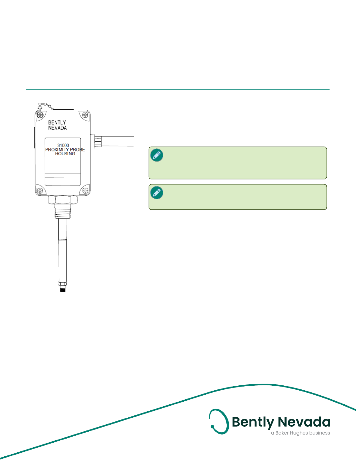
31000 and 32000 Proximity Probe Housing
Assemblies
Datasheet
Bently Nevada Machinery Condition Monitoring
Description
The 31000/32000 Proximity Probe Housing Assemblies are
recommended when mounting proximity probes through the
machine case and are typically used for radially mounted
transducers, whether vibration or Keyphasor measurements.
When using these housings to measure radial
vibration, ensure that the machine casing is affixed to
the bearing in order to get an accurate relative
vibration signal.
When measuring shaft axial position with dual
proximity probes, use housing 21022 instead. Consult
datasheet (Document 141601).
Use of a Proximity probe housing allows external access to
the proximity probe and its extension cable, permitting gap
adjustment or probe replacement without disassembly of the
machine. The 31000/32000 Proximity Probe Housing Assembly
is made of polyphenylene sulfide (PPS), an advanced, highstrength, thermoplastic with excellent corrosion resistance.
Other elements of the housing assembly are made of
corrosion-resistant stainless steel. The housing can be
ordered with installed 3300 XL Proximity Probes and a variety
of conduit fittings.
141610 Rev. K
The 31000/32000 Proximity Probe Housing Assembly is fully
compliant with the American Petroleum Institute's (API) 670
Standard for externally mounted proximity probe housings.
When installed in conjunction with an approved transducer
system and appropriate I.S. barriers, the 31000/32000
Proximity Probe Housing Assembly can be used in intrinsically
safe hazardous area applications.

31000 and 32000 Proximity Probe Housing Assemblies
Datasheet 141610 Rev. K
The 31000/32000 Housing is intended to
provide mechanical and environmental
protection only, and is not an explosionproof housing. When an explosion proof
proximity probe housing assembly is
required, use housing CA21000 or
CA24701. Consult the datasheet
(document 141600).
Related Documents
For probe information, refer to the following
manuals:
n 3300 XL 8mm & 3300 5mm Proximity
Transducer System User Guide
(Document 141078)
n 3300 XL NSv Proximity Transducer System
User Guide (Document 147357)
n 3300 XL 11mm Proximity Transducer
System Installation User Guide
(Document 146255)
n Radiation Resistant Probe and Proximitor
System (Document TW8029407)
2/14
31000 and 32000 Proximity Probe Housing Assemblies
Datasheet 141610 Rev. K
assembly of the probe, causing media
Specifications
Environmental
Temperature Range
-51 °C to +105 °C (-60 °F to + 221 °F)
Hot Water and Steam Exposure Effects
leakage into surrounding areas. Bently
Nevada, LLC, will not be held responsible
for any damages resulting from leaking
Proximity Probe Housing Assemblies. In
addition, Proximity Probe Housing
Assemblies and 3300 XL 8 mm proximity
probes will not be replaced under the
service plan due to probe leakage.
(Specification not guaranteed). Brief
periods (up to one week) of contact with
hot water (95°C [203°F]) and/or
condensing steam should not
significantly affect the strength of the
plastic housing. Contact with these
beyond this length of time may
eventually cause the strength of the
plastic housing to permanently
decrease during the first 6 to 8 weeks of
exposure, and then level at
approximately half of its initial value.
Tests of actual housing performance
after contact with hot water and
condensing steam have not been
conducted.
Probe Pressure
The 31000/32000 Proximity Probe Housing
Assembly is designed to seal differential
pressure between the probe tip and the
housing main body when used with a 3300 XL 8
mm probe. The sealing material internal to the
probe case consists of a Viton O-ring; the Oring between the sleeve and the housing is a
Neoprene O-ring. The plastic housing is certified
to seal against hose-directed water according
to NEMA 4X and IP66 standards but is not
designed to resist internal or external pressure.
Probes are not pressure tested prior to
shipment. Contact our custom design
department if you require a test of the pressure
seal for your application.
It is the responsibility of the customer or
user to ensure that all liquids and gases
are contained and safely controlled
should leakage occur from a Proximity
Probe Housing Assembly. Solutions with
high or low pH values may erode the tip
Mechanical
Type 4X rating certified by
Canadian Standards Association
(CSA). IP66 rating verified by
Protection
Ratings
Housing
Material
Sleeve Material
and Retaining
Chain
Outer Sleeve
and Exterior
Screws
O-Ring
Material
Recommended
Torque
(retaining nut)
Housing
Strength
(typical)
Housing
Impact
Strength
Weight 1.2 kg (2.6 lb) typical
SC115582-1 (e) 106. CENELEC
standard EN50014 rating for
electrostatic dissipation of a plastic
material located in a hazardous
area.
Glass-reinforced Polyphenylene
Sulfide (PPS) thermoplastic
containing conductive fibers
AISI 304 stainless steel
AISI 303 stainless steel
Neoprene
29.4 N·m (260 in·lb)
Outer sleeve was mounted on a test
stand with its axis parallel to
horizontal and the housing
mounted on the outer sleeve
through an end hole. The housing
supported 912 N (205 lb) placed
approximately 38 mm (1.5 inches)
from the unsupported end with the
cover fastened in place and
grounding liner installed.
Certified by BASEEFA to withstand
two separate 4 Joule (3.0 ft·lb)
impacts at -39°C (-38°F) and at 115
°C (239°F). Samples of the housing
and cover were verified by CSA to
withstand a 7 Joule (5.2 ft·lb)
impact at ambient room
temperature.
3/14

31000 and 32000 Proximity Probe Housing Assemblies
Datasheet 141610 Rev. K
Compliance and Certifications
FCC
This device complies with part 15 of the
FCC Rules. Operation is subject to the
following two conditions:
l This device may not cause harmful
interference.
l This device must accept any
interference received, including
interference that may cause
undesired operation.
RoHS
RoHS Directive 2011/65/EU
Hazardous Area Approvals
For the detailed listing of country and product
specific approvals, refer to the Approvals Quick
Reference Guide (108M1756) available from
Bently.com.
21000 and 24701
CA housings are certified by CSA for explosion proof applications in the following areas:
Class 1 Divisions 1 and 2 Groups C and
D
Class 2 Divisions 1 and 2 Groups E, F
North
America
and G
Class III
Enclosure Type 4
T5 @ Ta = -50 °C to +40 °C
T4 @ Ta = -50 °C to +80 °C
4/14
31000 and 32000 Proximity Probe Housing Assemblies
Datasheet 141610 Rev. K
English Proximity Probe Housing
Ordering Information
For the detailed listing of country and product
specific approvals, refer to the Approvals Quick
Reference Guide (108M1756) available from
Bently.com.
Table 1: Maximum "C" Option plus "D" Option
for different "B" Options (probe cable length)
Probe Cable
Length
0.5 meter 394 mm (15.5 in)
1.0 meter 760 mm (30.0 in)
Table 2: Maximum "C" Option plus "D" Option
for different "B" Options (probe cable length)
where P/N and S/N Label on Probe Cable is
visible outside of probe sleeve
Probe Cable
Length
0.5 meter 64 mm (2.5 in)
1.0 meter 483 mm (19.0 in)
Conduit fittings are necessary when
hardline conduit or metal tubing is
brought into the housing. Flexible
conduit should be ordered with integral
3/4-14 NPT fittings and do not require
additional conduit fittings with the
housing. If using flexible conduit, order
the "E" = 00 option.
Maximum C plus D
Maximum C plus D with Visible
P/N and S/N Label
Assemblies
31000 - AA-BB-CC-DDD-EE-FF
A: Probe with Connector
00 Probe not required
16 3300 XL 8 mm probe
26 3300 XL NSv probe
27 3300 XL NSv probe, multiple approvals
28 3300 XL 8 mm probe, multiple approvals
29
30
31 3300 XL NSv probe with connector protector
32
33 3300 XL 11 mm probe
34 3300 XL 11 mm probe, multiple approvals
35
36
B: Probe Cable Length
00 Probe cable not required
05 0.5 m (20 in)
10 1.0 m (39 in)
C: Standoff Adapter Length (Option C
Dimension)
15 Minimum length 1.5 in (38 mm)
75 Maximum length 7.5 in (191 mm)
3300 XL 8 mm probe, with connector
protector
3300 XL 8 mm probe, with connector
protector, multiple approvals
3300 XL NSv probe with connector protector,
multiple approvals
3300 XL 11 mm probe with connector
protector
3300 XL 11 mm probe with connector
protector, multiple approvals
Must be ordered if Standoff Adapter
Length option is not 00.
Recommendation
Order in increments of 0.5 in (13 mm)
D: Probe Penetration Option (Option D
Dimension)
10 Minimum length 1.0 in (25.4 mm)
5/14
Examples
1.5 in (38 mm) = 15
No standoff adapter = 00
Recommendation
Order in increments of 0.1 in (3 mm)

31000 and 32000 Proximity Probe Housing Assemblies
Datasheet 141610 Rev. K
Examples
No probe sleeve = 000
3.7 in (94 mm) = 037
2.4 in (569 mm) = 224
"C" plus "D" dimensions greater than 12 in
(305 mm) require additional sleeve
support near the probe to prevent
resonance from occurring. Sleeve
adjustment range of Probe Penetration
Option "D" is ±0.5 in (13 mm).
For probe penetration lengths between 1.0 and
2.0 inches, it may be necessary to counter bore
the machine case to reduce probe side view or
rear view effects.
E: Fittings
00 Without fittings
01 One 3/4-14 NPT fitting, two plugs.
02 Two 3/4-14 NPT fittings, one plug.
Two plugs, one 3/4-14 NPT fitting
One 3/4-14 to 1/2-14 NPT SST reducer
One cable seal grip with grommets for the
03
06
F: Mounting Thread Option
00 No outer sleeve, retainer, or retaining nut
02
05 7/8-14 UNF 2A
following cable sizes:
• 1/8 to 3/16 inches
• 1/4 to 5/16 inches
• 5/16 to 3/8 inches
One 3/4-14 NPT fitting
One 3/4-14 NPT to 1/2-14 NPR SST reducer
Two plugs
3/4-14 NPT (Required if ordering Standoff
Adapter Option).
Metric Proximity Probe Housing
Assemblies
32000 - AA-BB-CC-DDD-EE-FF
A: Probe with Connector
00 Probe not required
16 3300 XL 8 mm probe
26 3300 XL NSv probe
27 3300 XL NSv probe, multiple approvals
28 3300 XL 8 mm probe, multiple approvals
29
30
31 3300 XL NSv probe with connector protector
32
33 3300 XL 11 mm probe
34 3300 XL 11 mm probe, multiple approvals
35
36
B: Probe Cable Length
00
05 0.5 m (20 in)
10 1.0 m (39 in)
C: Standoff Adapter Length (Option C
Dimension)
04 Minimum length 40 mm
20 Maximum length 200 mm
D: Probe Penetration Option (Option D
Dimension)
760 Maximum length 760 mm
025 Minimum length 25 mm
Examples
3300 XL 8 mm probe, with connector
protector
3300 XL 8 mm probe, with connector
protector, multiple approvals
3300 XL NSv probe with connector protector,
multiple approvals
3300 XL 11 mm probe with connector
protector
3300 XL 11 mm probe with connector
protector, multiple approvals
Probe cable not required (Option A must also
be 00)
Must be ordered if Standoff Adapter
Length option is not 00.
Recommendation
Order in increments of 10 mm
Recommendation
Order in increments of 1.0 mm
6/14

31000 and 32000 Proximity Probe Housing Assemblies
Datasheet 141610 Rev. K
No probe sleeve = 000
50 mm = 050
760 mm = 760
"C" plus "D" dimensions greater than 12 in
(305 mm) require additional sleeve
support near the probe to prevent
resonance from occurring. Sleeve
adjustment range of Probe Penetration
Option "D" is ±0.5 in (13 mm).
For probe penetration lengths between 25 and
50 millimeters, it may be necessary to counter
bore the machine case to reduce probe side
view or rear view effects.
E: Fittings
00
01 One M25 fitting, two plugs.
02 Two M25 fittings, one plug.
03
05 One DIN PG11 fitting, two plugs
07
08
F: Mounting Thread Option
00 No outer sleeve, retainer, or retaining nut
01 M24 X 3
02
Without fittings; two plugs and two
washers.
Two plugs, one M20 fitting
One cable seal grip with grommets for
armored probe cable
One PG21 x M20 fitting
Two plugs
Two PG21 x M20 fittings
One plug
3/4-14 NPT (Required if ordering Standoff
Adapter Option.)
Terminal Housing
106769-AA
The 106769 housing consists of a 31000-style
PPS housing with two terminal mounting blocks
(each terminal block has four terminals)
mounted in each housing. Sixteen ring lugs are
supplied loose inside the housing for
connecting transducer cables. Conduit fittings
are 3/4-14 NPT chrome-plated zinc fittings.
A: Conduit Fitting Option
00 No fittings
01 One fitting
02 Two fittings
7/14

31000 and 32000 Proximity Probe Housing Assemblies
Datasheet 141610 Rev. K
AAA Option for
Accessories
Part Number Description
Probe Support / Oil Seal
37948-01
124200 31000 and 32000 User Guide
Recommended for sleeves longer
than 305 mm (12 in)
31000
ProxProbe
Housing
Housing AAA
option for 3300
XL 11 mm probe
option (A: 33 or
A: 34)
Standoff Adapter Option from
original housing (31000 option C)
+ Probe penetration option from
original housing (31000 option D)
+ 0 1 7.
Example
Original part number 31000-3310-30-113-01-02
Description
English Probe Sleeve for 31000
Proximity Probe Housings
AAA option for replacement sleeve
(030 + 113 + 017) = 1 6 0.
108883-AAA
A: Measured Probe Sleeve Length
Recommendation
Order in increments of 0.1 in (3 mm)
The individual probe sleeve length does not
include the distance from the end of the sleeve
to the probe tip or the gap from the probe tip to
the target material. If only the part number of
the original housing is known, and the sleeve
cannot be measured, use the following table to
determine the sleeve length:
AAA Option for
31000
ProxProbe
Housing
Housing AAA
option for 3300
XL 8 mm probe
option (A: 16 or
A: 28)
Standoff adapter option from
original housing (31000 option C)
+ Probe penetration option from
original housing (31000 option D)
+ 0 2 5.
Example
Original part number 31000-16-1015-035-03-02
Description
Minimum Probe Sleeve Length
3300 XL 8 mm probes 3.5 in (89 mm) = 0 3 5
3300 XL NSv probe 3.6 in (91 mm) = 0 3 6
3300 XL 11 mm probe 2.7 in (69 mm) = 0 2 7
Maximum Probe Sleeve Length
3300 XL 0.5 meter 8 mm
probe
3300 XLNSv 0.5 meter
probe
3300 XL 0.5 metre 11 mm
probe
3300 XL 1.0 meter 8 mm
probe
3300XL NSv 1.0 meter
probe
3300 XL 1.0 meter 11 mm
probe
18.0 in (457 mm) = 180
18.1 in (460 mm) = 181
16.0 in (406 mm) = 160
32.5 in (826mm) = 325
32.6 in (828mm) = 326
31.7 in (805 mm) = 317
Housing AAA
option for 3300
XL NSv probe
option (A: 26 or
A: 27)
AAA option for replacement sleeve
(015 + 035 + 025) = 075
Standoff adapter option from
original housing (31000 option C)
+ Probe penetration option from
original housing (31000 option D)
+ 0 2 6.
Example
Original part number 31000-2710-20-035-03-02
AAA option for replacement sleeve
(020 + 035 + 026) = 0 8 1.
8/14

31000 and 32000 Proximity Probe Housing Assemblies
Datasheet 141610 Rev. K
Metric Probe Sleeve for 32000
Proximity Probe Housings
108882-AAA
A: Measured Probe Sleeve Length
The individual probe sleeve length does
not include the distance from the end of
the sleeve to the probe tip or the gap
from the probe tip to the target material.
If only the part number of the original
housing is known, and the sleeve
cannot be measured, use the following
table to determine the sleeve length:
AAA Option for
32000
ProxProbe
Housing
Housing AAA
option for 3300
XL 8 mm probe
option (A: 16 or
A: 28)
Recommendation
Order in increments of 1 mm (0.04 in).
Description
Standoff adapter option from
original housing (32000 option C)
*10 + Probe penetration option
from original housing (32000
option D) + 063.
Example
Original part number 32000-16-1008-205-03-02
AAA Option for
32000
ProxProbe
Housing
AAA option for replacement
sleeve (100 + 105 +042)=247
Description
Minimum Probe Sleeve Length
3300 XL 8 mm probes 88 mm (3.5 in) = 088
3300 XL NSv probe 91 mm (3.6 in) = 091
3300 XL 11 mm probe 67 mm (2.6 in) = 067
Maximum Probe Sleeve Length
3300 XL 0.5 meter 8 mm
probe
3300 XLNSv 0.5 meter
probe
3300 XL 0.5 metre 11 mm
probe
3300 XL 1.0 meter 8 mm
probe
3300XL NSv 1.0 meter
probe
3300 XL 1.0 meter 11 mm
probe
457 mm (18.0 in) = 457
460 mm (18.1 in) = 460
436 mm (17.2 in) = 436
823 mm (32.4 in) = 823
826 mm (32.5 in) = 826
802 mm (31.6 in) = 802
Housing AAA
option for 3300
XL NSv probe
option (A: 26 or
A: 27)
Housing AAA
option for 3300
XL 11 mm probe
option (A: 33 or
A: 34)
AAA option for replacement sleeve
(080 + 205 + 063) = 348
Standoff adapter option from
original housing (32000 option C)
*10 + probe penetration option
from original housing (32000
option D) + 066.
Example
Original part number 32000-2710-10-105-03-02
AAA option for replacement sleeve
(100 + 105 + 066) = 271.
Standoff Adapter Option from
original housing (32000 option C)
* 10 + Probe penetration option
from original housing (32000
option D) + 042.
Example
Original part number 32000-3310-10-105-03-02
9/14

31000 and 32000 Proximity Probe Housing Assemblies
Datasheet 141610 Rev. K
English Standoff Adaptor
109319-AAA
A: Individual Standoff Adapter Length
Hex 1 3/8 in; threads = 3/4-14 NPT
015 Minimum length 1.5 in (38 mm)
075 Maximum length 7.5 in (191 mm)
Recommendation
Order in increments of 0.5 in (13
mm)
Metric Standoff Adaptor
109318-AA
A: Individual Standoff Adapter Length
Wrench Flats 35 mm; threads = 3/4-14 NPT
04 Minimum length 40 mm
20 Maximum length 200 mm
Recommendation Order in increments of 10 mm
Example 120 mm = 12
For desired probe penetration lengths of
less than 25 mm (1.0 in), order a
separate Individual Standoff Adapter.
The effective probe penetration length will then
be reduced by the length of the Individual
Standoff Adapter, plus an additional 13 mm (0.5
in) due to the NPT thread engagement.
Spare 3300 XL 8 mm Reverse
Mount Probe, 3/8-24 UNF threads
330105-02-12-CC-DD-EE
Spare 3300 XL 8 mm Reverse
Mount Probe, M10 X1 threads
330106-05-30-CC-DD-EE
C: Total Length
05 0.5 meter (1.6 feet)
10 1.0 meter (3.3 feet)
15 1.5 meter (4.9 feet)
20 2.0 meters (6.6 feet)
50 5.0 meters (16.4 feet)
90 9.0 meters (29.5 feet)
D: Connector
00 Connector not installed
02 Miniature ClickLoc coaxial connector
E: Agency Approval
00 Not required
05 Multiple approvals
Example:
To create a probe penetration length 13 mm
(0.5in), order a 31000 housing with DDD (probe
penetration) option of 030 [76 mm (3 in)] and a
separate individual standoff adapter that is 51
mm (2.0 in) in length (part number 21003-020).
The standoff adapter covers 38 mm (2.0 in) of
the probe sleeve plus an additional 13 mm (0.5
in).
Therefore, the effective probe penetration
length drops to 13 mm (0.5 in).
If you use effective penetration lengths of less
than 1.0 inches, signal effects are likely due to
probe side view or rear view of metal
components.
10/14

31000 and 32000 Proximity Probe Housing Assemblies
Datasheet 141610 Rev. K
Spare 3300 NSV Reverse Mount
Probe, 3/8-24 UNF threads
330906-02-12-CC-DD-EE
Spare 3300 NSV Reverse Mount
Probe, M10 X1 threads
330907-05-30-CC-DD-EE
C: Total Length
05 0.5 meter (1.6 feet)
10 1.0 meter (3.3 feet)
50 5.0 meters (16.4 feet)
90 9.0 meters (29.5 feet)
D: Connector
00 Connector not installed
02 Miniature ClickLoc coaxial connector
E: Agency Approval
00 Not required
05 Multiple approvals
Heavy Duty Conduit and Cable
Fittings
03813103
03818100
03818101
03818102
03818103
03818104 AISI 303 Stainless Steel Cable Gland, PG11
03818105 AISI 316 Stainless Steel Cable Gland, M20
03818111
26650-01AISI 303 Stainless Steel Reducer, 3/4-14
Chrome-plated Zinc Conduit Fitting, 3/414 NPT
AISI 316 Stainless Steel Conduit Fitting,
3/4-14 NPT
AISI 316 Stainless Steel Conduit Fitting,
PG21 x M25
AISI 316 Stainless Steel Conduit Fitting,
PG21 x M20
AISI 316 Stainless Steel Conduit Fitting,
PG21 x PG11
Nickel-plated Brass Conduit Fitting, PG21 x
M20
NPT to 1/2-14 NPT
Sleeve and Blanking Plugs
104968-01
104968-02
Plugs fill opening when sleeve is removed
from machine case.
104288-01 English Blanking Plug
104288-02 Metric Blanking Plug
Plugs fill extra holes in plastic housing
where needed.
English Sleeve Plug, threaded,
303 stainless steel
Metric Sleeve Plug, threaded,
303 stainless steel.
11/14

31000 and 32000 Proximity Probe Housing Assemblies
Datasheet 141610 Rev. K
Graphs and Figures
Figure 1: Dimensions for 31000 and 32000 Proximity Probe Housings
Dimensions are in millimeters (inches).
12/14

31000 and 32000 Proximity Probe Housing Assemblies
Datasheet 141610 Rev. K
All 4 holes in housing base, 1 per side, will accept sleeve or conduit fittings and cable glands.
Fittings are supplied with housing depending on English, metric or DIN type.
Hole plugs are provided to seal unused holes.
Installation Procedures
1. Install outer sleeve into machine case.
2. Insert probe sleeve and adjust probe gap.
3. Disconnect probe cable and fit housing over outer sleeve.
4. Slide retainer under retaining nut. Tighten nut.
5. Re-connect probe cable and Connector Protector.
6. Place housing cover on housing and tighten captive screws.
7. If hole plugs are used, tighten hole plug nuts to 0.5 N-m (5 in-lbs).
Figure 2: Vertical and Horizontal Profile Views of the 31000 and 32000 Proximity Probe Housings
13/14

31000 and 32000 Proximity Probe Housing Assemblies
Datasheet 141610 Rev. K
Copyright 2020 Baker Hughes Company. All rights reserved.
Bently Nevada, Orbit Logo, Keyphasor and Proximitor are registered trademarks of Bently Nevada, a Baker Hughes
Business, in the United States and other countries. The Baker Hughes logo is a trademark of Baker Hughes Company.
All other product and company names are trademarks of their respective holders. Use of the trademarks does not
imply any affiliation with or endorsement by the respective holders.
Baker Hughes provides this information on an “as is” basis for general information purposes. Baker Hughes does not
make any representation as to the accuracy or completeness of the information and makes no warranties of any
kind, specific, implied or oral, to the fullest extent permissible by law, including those of merchantability and fitness
for a particular purpose or use. Baker Hughes hereby disclaims any and all liability for any direct, indirect,
consequential or special damages, claims for lost profits, or third party claims arising from the use of the
information, whether a claim is asserted in contract, tort, or otherwise. Baker Hughes reserves the right to make
changes in specifications and features shown herein, or discontinue the product described at any time without
notice or obligation. Contact your Baker Hughes representative for the most current information.
The information contained in this document is the property of BakerHughes and its affiliates; and is subject to
change without prior notice. It is being supplied as a service to our customers and may not be altered or its content
repackaged without the express written consent of Baker Hughes. This product or associated products may be
covered by one or more patents. See Bently.com/legal.
1631 Bently Parkway South, Minden, Nevada USA 89423
Phone: 1.775.782.3611 or 1.800.227.5514 (US only)
Bently.com
14/14
 Loading...