

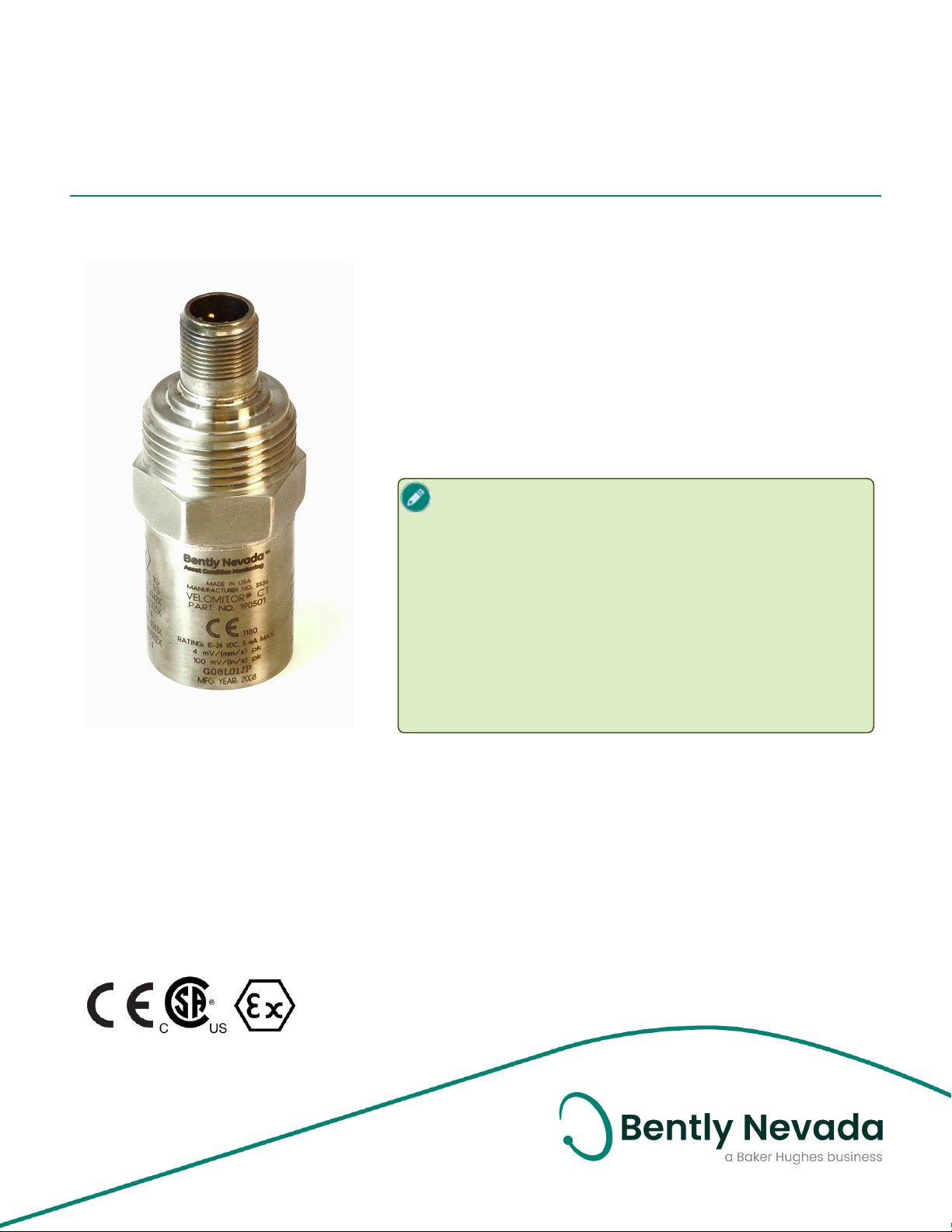
190501 Velomitor CT Transducer
Datasheet
Bently Nevada Machinery Condition Monitoring
Description
The Velomitor CT Velocity Transducer is a low-frequency
version of our standard Velomitor Piezo-velocity Sensor. Its
design specifically measures casing vibration velocity on
cooling tower and air-cooled heat-exchanger fan assemblies
that operate at or above 90 rpm (100 to 300 rpm typical).
The Velomitor CT Transducer can measure vibration
amplitudes at these frequencies as well as the vibration
frequencies generated by the fan motor and speed reducer.
If you are measuring a machine housing to determine
where to install transducers, consider what kinds of
data you need to obtain. Most common machine
malfunctions (imbalance, misalignment, and so forth)
originate at the rotor and cause a change in rotor
vibration. The location you select on the housing must
accurately conduct rotor vibration to the transducer.
Install the transducer carefully. If you don't, the
transducer may not accurately detect vibrations and
can transmit invalid data. Bently Nevada provides
engineering services to accurately measure machine
housings and to install transducers.
141636 Rev. AC

190501 Velomitor CT Transducer
Datasheet 141636 Rev. AC
kHz) Typical Low Frequency Noise
Specifications
Parameters are specified from +20 °C to +30 °C
(+68 °F to +86 °F) and 100 Hz unless otherwise
indicated.
Operating the transducer outside the
specified limits will result in false
readings or loss of machine monitoring.
Base Strain
Sensitivity
Grounding Internal electronics are isolated
Maximum
Cable
Length
Floor on page16.
0.43 mm/s/μstrain (0.017
in/s/μstrain).
from case.
305 metres (1,000 ft.) of cable
(part number 02173006) with
no degradation of signal.
Electrical
Maximum continuous length of cable
Sensitivity 3.94 mV/mm/s (100 mV/in/s)
±5%.
Frequency
Response
3.0 Hz to 900 Hz (180 to 54,000
cpm) ±1.0 dB
available is 91.44 metres (300 ft.) If
longer lengths are required they must
be spliced or have a connector
installed on them.
Temperature
Sensitivity
Velocity
Range
Transverse
Response
Amplitude
Linearity
Mounted
Resonant
Frequency
Output Bias
Voltage
1.5 Hz to 1.0 kHz (90 to 60,000
cpm) ±3.0 dB
-8% to +5% typical over the
operating temperature range.
63.5 mm/s pk (2.5 in/s pk) see
Operating Range for Metric
Units on page14. See Operating
Range for English Units on
page15.. Vibration
components in excess of 10g pk
above 1 kHz can significantly
reduce this range.
Less than 5% of the axial
sensitivity.
±2% to 63.5 mm/s pk (2.5 in/s
pk)
9 kHz, minimum (stud
mounted, except quick
disconnect)
10.1 Vdc ± 1.0 Vdc, Pin A
referenced to Pin B
Environmental Limits
Operating
Temperature
Storage
Temperature
Shock Limit 5000 g pk, maximum.
Humidity
Limit
Magnetic
Field
Susceptibility
-40 °C to +85 °C (-40 °F to +185
°F).
-40 °C to +100 °C (-40 °F to +212
°F).
100% condensing,
non-submerged.
<0.0068 mm/s/gauss (0.268
mil/s/gauss) @ 50 gauss, 5060Hz
Dynamic
Output
Impedance
Broadband
Noise Floor
(1.5 Hz to 1
<400 Ω typical
0.229 mm/s (0.009 in/s) pk.
For more information, see
2/17

190501 Velomitor CT Transducer
Datasheet 141636 Rev. AC
Mechanical
Weight <297 g (10.5 oz.), typical.
Mounting
Surface
Height 82 mm (3.2 in).
Case
Material
Connector 2-pin 316L stainless steel MIL-C-
Mounting
Torque
Polarity Pin A goes positive with respect
Mounting
Angle
For more information on this product,
please refer to the Velomitor CT PiezoVelocity Transducer User Guide (document
125389).
33 mm diameter (1.3 in
diameter).
316L stainless steel
5015, top.
4.5 N-m ± 0.6 N-m (40 in–lbf ± 5
in-lbf).
to Pin B when velocity is from
base to top of the transducer.
Any orientation.
3/17

190501 Velomitor CT Transducer
Datasheet 141636 Rev. AC
Compliance and Certifications
FCC
This device complies with part 15 of the
FCC Rules. Operation is subject to the
following two conditions:
l This device may not cause harmful
interference.
l This device must accept any
interference received, including
interference that may cause
undesired operation.
EMC
EMC Directive 2014/30/EU
RoHS
RoHS Directive 2011/65/EU
Maritime
330400and 330425 only
ABS 2009 Steel Vessels Rules
1-1-4/7.7,4-8-3/1.11.1,4-9-7/13
Hazardous Area Approvals
For the detailed listing of country and
product specific approvals, refer to the
Approvals Quick Reference Guide
(108M1756) available from Bently.com.
CSA/NRTL/C
190501 (Agency Approval Options 01
through 04)
Intrinsically
Safe
Ex ia IIC T4:
Class I, Div 1, Groups A, B, C, D.
Class II, Group E, F and G
Class III
AEx ia IIC T4:
Class I, Div 1, Groups A, B, C, D;
Class II, Groups E, F, G
Class III
Install per drawing 167536
T4 @ -40 °C ≤ Ta ≤ +100 °C
(-40 °F ≤ Ta ≤ +212 °F)
Intrinsically
Safe and
NonIncendive
330400,
330425
330500 Ex ia IIC T4
330525 Ex ia IIC T4
Ex nL IIC T4
Class I, Division 2, Groups A, B, C
and D
AEx nA T4
Class I, Division 2, Groups A, B, C
and D
Install per drawing 167536
T4 @ -40 °C ≤ Ta ≤ +100 °C
(-40 °F ≤ Ta ≤ +212 °F)
Ex ia IIC T4
AEx ia IIC T4
Class I, Div 1 Groups A, B, C and D
Class II, Groups E, F, and G
Class III
T4 @ -40°C ≤ Ta ≤ 100°C
Install per dwg 167538
AEx ia IIC T4
Class I, Division 1, Groups A, B, C
and D Class II, Groups E, F, G
Class III
Install per dwg 167537
T4 @ -40°C ≤ Ta ≤ 100°C
Ex nL IIC T4
AEx nA IIC T4
Class I, Div 2, Groups A, B, C, D
Install per dwg 167537
T4 @ -40°C ≤ Ta ≤ 100°C
AEx ia IIC T4
Class I, Division 1, Groups A, B, C
and D Class II, Groups E, F, G
Class III
T4 @ -40°C ≤ Ta ≤ 100°C
4/17
190501 Velomitor CT Transducer
Datasheet 141636 Rev. AC
Ex nL IIC T4
AEx nA IIC T4
Class I, Div 2, Groups A, B, C, D
Install per dwg 167539
T4 @ -40°C ≤ Ta ≤ 100°C
ATEX/IECEx
190501, 330400, 330425, 330500, 330525
190501
Entity
Parameters
II 1 G
Ex ia IIC T4 Ga
II 3 D
Ex na IIC T4 Gc
Ex tc III T130°C Dc
T4@ Ta = -55°C to 121°C
Zone 0/1 Zone 2
Ui= 30V Ui= 30V
Ii= 200mA Ii= 200mA
Ci-10.8nF
Li= 0
330400, 330425,
330500, 330525
Entity
Parameters
Pi= 0.75W Pi= 1.14W
Ci-27.2nF
Li= 0
II 1 G
Ex ia IIC T4 Ga
II 3 D
Ex na IIC T4 Gc
Ex tc III T130°C Dc
T4@ Ta = -55°C to 121°C
Zone 0/1 Zone 2
Ui= 28V Ui= 28V
Ii= 150mA Ii= 150mA
Pi= 0.84W Pi= 1.26W
5/17

190501 Velomitor CT Transducer
Datasheet 141636 Rev. AC
Hazardous Area Conditions of Safe Use
ATEX/IECEx
Zone 0/1:
Equipment must be connected to equipment,
which meets the abovelisted entity parameters.
The cables type A or B (in compliance with EN
60079-25) must respect the cable parameters
listed with the entity parameters.
Zone 2 :
The supply electrical parameters shall not
exceed the values mentioned in the tables
above.
6/17

190501 Velomitor CT Transducer
Datasheet 141636 Rev. AC
NPT
Ordering Information
Velomitor CT Velocity Transducer
190501 - AA - BB - CC
A: Mounting Hardware Option
0 0 No stud
0 1 Stud 3/8-in 24 to 3/8-in 24
0 2 Stud 3/8-in 24 to 1/2-in 20
0 3 Adhesive Stud 3/8-in 24
0 4 Stud M6x1 with 3/8-in 24 adapter
0 5 Adhesive Stud M6x1 with 3/8-24
adapter
0 6 Stud 3/8-in 24 to 1/4-in 28
0 7 Plate Stud 3/8-in 24 to 3/8-in 24
0 8 Plate Stud 3/8-in 24 to 1/2-in 20
0 9 Plate Stud 3/8-in 24 to 1/4-in NPT
1 0 Plate Stud M6x1 to M6x1with 3/8-
in 24 adapter
1 1 Plate Stud 3/8-in 24 to 1/4-in 28
1 2 Plate Stud 3/8-in 24 to M8x1
1 3 Quick disconnect stud
1 4 Adapter, 3/8-in 24 to 1/4-in 20
1 5 Adapter, 3/8-in 24 to 5/16-in 18
1 6 Adapter, 3/8-in 24 to 3/8-in 24
1 7 Adapter, 3/8-in 24 to 3/8-in 16
1 8 Adapter, 3/8-in 24 to 1/2-in 13
1 9 Adapter, 3/8-in 24 to 1/4-in 18
NPT
2 2 Adapter, 3/8-in 24 to 3/4-in 14
NPT
2 3 Adapter, 3/8-in 24 to 1.0-in 11.5
NPT
2 4 Adapter, 3/8-in 24 to 1.25-in 11.5
NPT
B: Connection Option
0 0 MIL-C-5015 connection interface
9 9 Unit with included 32-foot cable
C: Agency Approval Option
0 0 No Approvals
0 1 through
0 4
CSA/NRTL/C (Class I, Division 1),
ATEX/IECEx/CSA (Class I, Zone
0/1)
Interconnect Cable
CB2W100 - AAA
Description: Connectors: MIL-C 5015, 2 Socket,
Splash Proof, Premium, isolated to blunt cut,
Cable: 20 AWG, twisted pair, shielded, yellow
Teflon jacket. LOCKING RING, ADAPTER SEAL,
AND O-RING ARE INCLUDED.
A: Length
0 1 5 15 feet (4.57 metres)
0 3 2 32 feet (9.75 metres)
0 6 4 64 feet (19.5 metres)
1 1 2 112 feet (34.1 metres)
1 2 5 125 feet (38.1 metres)
1 5 0 150 feet (45.7 metres)
2 0 0 200 feet (61.0 metres)
2 0 Adapter, 3/8-in 24 to 3/8-in 18
NPT
2 1 Adapter, 3/8-in 24 to 1/2-in 14
2 5 0 250 feet (76.2 metres)
Accessories
7/17

190501 Velomitor CT Transducer
Datasheet 141636 Rev. AC
128608-02 1/2-in NPT conduit adapter
04284020-01Adhesive mount base kit. The
adhesive mount base kit design
is for machines with thin casings
that do not permit drilling and
tapping a mounting hole. Kit
contains material (adhesive
and bases) for 2 each 3/8-in 24
UNF adhesive-mount bases.
One kit can outfit 2 Velomitor CT
Transducers.
transducer without rotating it, allowing you to
keep the cable connected to the transducer.
128689-01 3/8-in 24 to 1¾-in 16 quick
disconnect stud base. Attached
to the machine.
43055-01 1¾-in 16 mounting base nut.
Interface between stud base
and transducer piece.
128690-01 3/8-in 24 quick disconnect stud
transducer piece. Attached to
the Velomitor CT Transducer.
Spare Mounting Adapters
All mounting adapters are made from 300
series stainless steel.
Standard Studs
Fittings
Conduit fittings allow connection of flexible,
metal, liquid-tight conduit or armor to the
conduit adapter.
04365657 3/8-in 24 to 3/8-in 24 stud
87910-01 3/8-in 24 to 1/2-in 20 stud
87931-01 M6x1 to M6x1 metric stud
(requires metric adapter)
87055-01 3/8-in 24 to M6x1 metric adapter
89139-01 3/8-in 24 to 1/4-in 28 stud
Hex Plate Studs
107756-01 3/8-in 24 to 3/8-in 24 plate stud
107755-01 3/8-in 24 to 1/2-in 20 plate stud
107754-01 3/8-in 24 to 1/4-in NPT plate stud
107757-01 M6x1 to M6x1 plate stud (requires
metric adapter)
125094-01 3/8-in 24 to M8x1 metric plate
stud
128038-01 3/8-in 24 to 1/4-in 28 Plate Stud
Quick Disconnect Components
The following three components are included
with the quick disconnect mounting option for
the Velomitor CT Transducer. The quick
disconnect option allows you to remove the
03839201 1/2-in NPT straight male conduit
fitting. For connecting flexible,
liquid-tight conduit to the
conduit adapter or a
weatherproof enclosure.
03850000 1/2-in NPT straight, male
compression-type fitting. For
connecting Teflon™-coated
3/8-in stainless steel armor to
the transducer or a
weatherproof enclosure. Fitting
will fit Teflon™-coated armor
with a maximum outer diameter
of 13.8 mm (0.543 in) (including
Teflon™ thickness).
[caption]
Teflon-Coated Stainless Steel
Armor
106924-AA
This part includes the Teflon-coated
armor but not the cable. You will require
2 1/2-in NPT compression fittings (part
number 03850000) to attach the armor
to the conduit adapter and terminate it
at an enclosure.
8/17

190501 Velomitor CT Transducer
Datasheet 141636 Rev. AC
A: Armor Length Option in Feet
Order in increments of 10 ft (3.0 m)
Minimum Length: 10 ft (3.0 m)
Maximum Length: 60 ft (18.3 m)
Flexible Metal Conduit
14847-AA
A: Flexible Conduit Length Option in Feet
Order in increments of 1 ft (0.3 m)
Minimum Length: 01 ft (0.3 m)
Maximum Length: 99 ft (30.2 m)
106769-01 Terminal housing. Provides a
convenient interface between
the transducer signal cable and
monitor signal cable.
9/17

190501 Velomitor CT Transducer
Datasheet 141636 Rev. AC
Graphs and Figures
Note: All dimensions shown are in millimeters (inches) unless noted otherwise.
1. 1/2” NPT x 12.2 DP (1/2” NPT x 0.48 DP)
2. 35.6 (1.40) diameter
3. Cable (not included)
4. Conduit adaptor P/N 128608-02 (not included)
5. 31.8 (1.25) hex flat
6. 31.5 (1.24) diameter
7. 3/8-24 UNF X 8.9 DP (3/8-24 UNF X 0.35 DP)
Figure 1: Velomitor CT Outline Drawing
10/17

190501 Velomitor CT Transducer
Datasheet 141636 Rev. AC
Spare Mounting Adapters
All mounting adapters are made from 300 series stainless steel. Illustrations shown are not to
scale.
Table 1: Standard Studs
Part Number Size Illustration
04365657 3/8-24 to 3/8-24
87055-01 3/8-24 to M6X1
87910-01 3/8-24 to 1/2-20
87931-01 M6X1 to M6X1
89139-01 3/8-24 to 1/4-28
Table 2: Adhesive Studs
Part Number Size Illustration
04284020 3/8-24
Table 3: 1-3/8 Hex Plate Studs
11/17

190501 Velomitor CT Transducer
Datasheet 141636 Rev. AC
Part Number Size Illustration
107754-01 3/8-24 UNF to 1/4 NPT
107755-01 3/8-24 UNF to 1/2-20 UNF
107756-01 3/8-24 to 3/8-24
197757-01 M6X1 to M6X1
125094-01 3/8-24 UNF to M8X1
128038-01 3/8-24 UNF to 1/4-28 UNF
Table 4: Quick Disconnect Studs
Part Number Description Illustration
43055-01 Union Mounting Base Nut
128689-01 Quick Disconnect Stud Base
12/17

190501 Velomitor CT Transducer
Datasheet 141636 Rev. AC
Part Number Description Illustration
128690-01 Quick Disconnect Transducer
Piece
Graphs
Figure 2: Typical Phase Response
Figure 3: Typical Amplitude Response
13/17

190501 Velomitor CT Transducer
Datasheet 141636 Rev. AC
1. Velocity axis (mm/s peak-peak)
2. Displacement axis (mm peak-peak)
3. Acceleration axis (m/s2 peak-peak)
Figure 4: Operating Range for Metric Units
14/17

190501 Velomitor CT Transducer
Datasheet 141636 Rev. AC
1. Velocity axis (in./s peak-peak)
2. Displacement axis (in. peak-peak)
3. Acceleration axis (g peak-peak)
Figure 5: Operating Range for English Units
15/17

190501 Velomitor CT Transducer
Datasheet 141636 Rev. AC
Figure 6: Typical Low Frequency Noise Floor
16/17

190501 Velomitor CT Transducer
Datasheet 141636 Rev. AC
Copyright 2020 Baker Hughes Company. All rights reserved.
Bently Nevada, Orbit Logo and Velomitor are registered trademarks of Bently Nevada, a Baker Hughes Business, in the
United States and other countries. The Baker Hughes logo is a trademark of Baker Hughes Company. All other
product and company names are trademarks of their respective holders. Use of the trademarks does not imply any
affiliation with or endorsement by the respective holders.
Baker Hughes provides this information on an “as is” basis for general information purposes. Baker Hughes does not
make any representation as to the accuracy or completeness of the information and makes no warranties of any
kind, specific, implied or oral, to the fullest extent permissible by law, including those of merchantability and fitness
for a particular purpose or use. Baker Hughes hereby disclaims any and all liability for any direct, indirect,
consequential or special damages, claims for lost profits, or third party claims arising from the use of the
information, whether a claim is asserted in contract, tort, or otherwise. Baker Hughes reserves the right to make
changes in specifications and features shown herein, or discontinue the product described at any time without
notice or obligation. Contact your Baker Hughes representative for the most current information.
The information contained in this document is the property of BakerHughes and its affiliates; and is subject to
change without prior notice. It is being supplied as a service to our customers and may not be altered or its content
repackaged without the express written consent of Baker Hughes. This product or associated products may be
covered by one or more patents. See Bently.com/legal.
1631 Bently Parkway South, Minden, Nevada USA 89423
Phone: 1.775.782.3611 or 1.800.227.5514 (US only)
Bently.com
17/17
 Loading...