

Page 1
D
Bedienungsanleitung
Operating manual
NULL
PV 1-1
5
%
ON/OFF
press 2 sec.
Auto
R
PE
Ω
V
NULL
DIN EN 62446 (VDE 0126-23), ÖVE/ÖNORM EN 62446
ISO
500V
250V 1000V
BENNING PV 1-1
Page 2
D
2
3
4
K
PV 1-1
NULL
5
%
ON/OFF
press 2 sec.
R
Ω
NULL
DIN EN 62446 (VDE 0126-23), ÖVE/ÖNORM EN 62446
Auto
PE
V
ISO
500V
250V 1000V
9JL
8
7
6
5
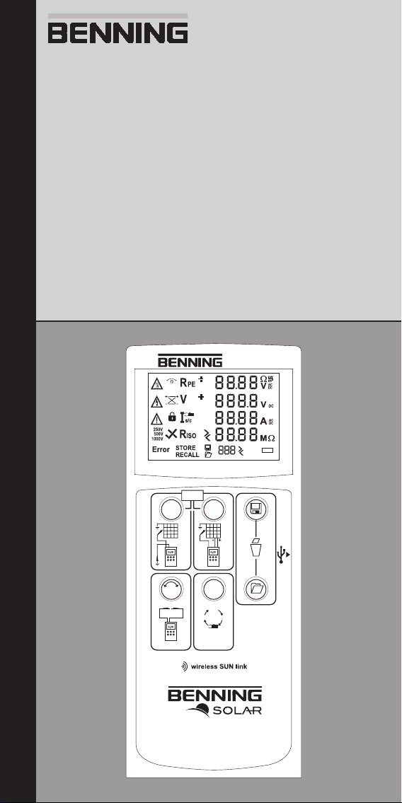
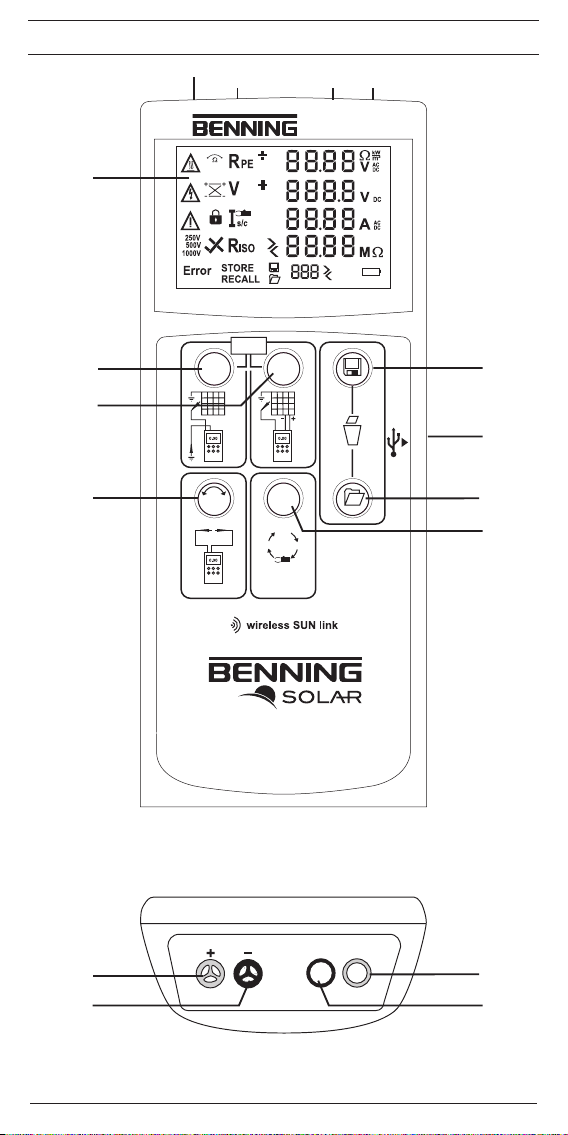
Bild 1: Gerätefrontseite
Fig. 1: Appliance front face
9
Bild 2: Geräteoberseite
Fig. 2: Top side of the device
09/ 2012
CAT I
1000 V
10 A
BENNING PV 1-1
CAT III
300 V
L
KJ
Page 3
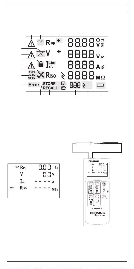
Bild 3: Digitalanzeige
NULL
5
%
PV 1-1
Fig. 3: Digital display
E
F
G
H
I
J
D
ABCD
NULL
K
L M N O P
Bild 4: Nullabgleich der Sicherheitsmessleitung für
R
-Messung
PE
Fig. 4: Null balance of the measuring lead for RPE
measurement
NULL
5
%
NULL
ON/OFF
press 2 sec.
R
PE
Ω
NULL
DIN EN 62446 (VDE 0126-23), ÖVE/ÖNORM EN 62446
250V 1000V
PV 1-1
Auto
V
ISO
500V
09/ 2012
BENNING PV 1-1
Page 4
D
PV 1-1
PV 1-1
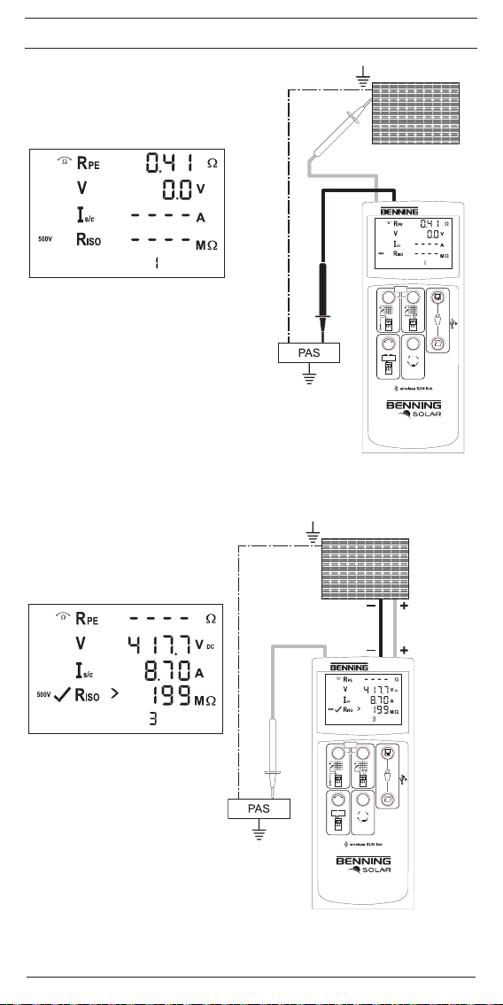
Bild 5: Prüfung des Schutzleiterwiderstandes R
Fig. 5: Testing the protective conductor resistance (RPE)
PE
PV-Modul/ -Strang
PV-module/ -string
NULL
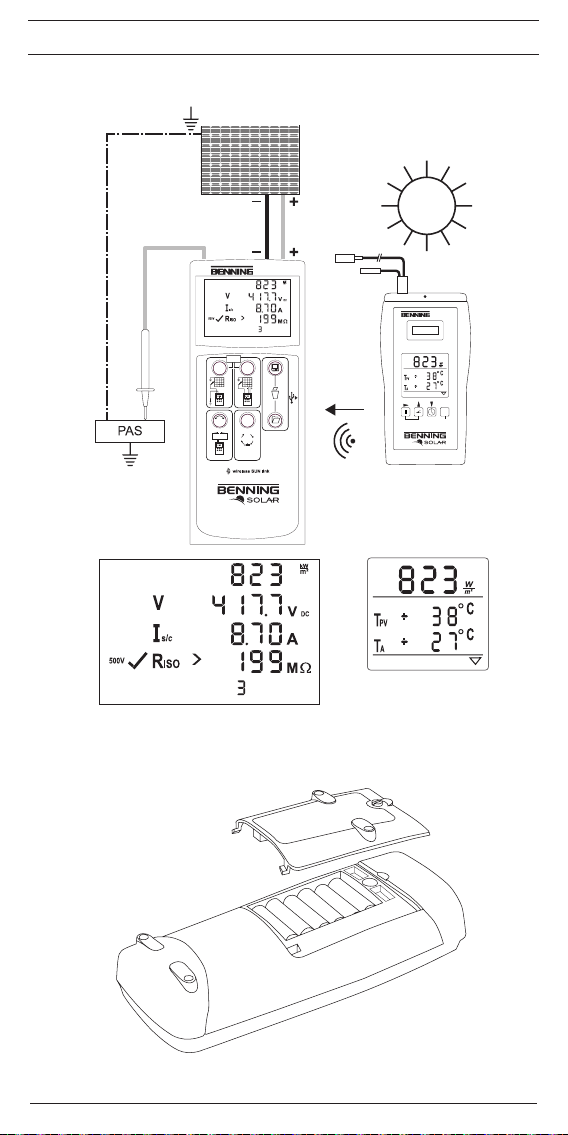
Bild 6: Automatische Solarmodul-Messung, ISO-
Messung über Erdleiter
Fig. 6: Automatic solar panel measurement, ISO
measurement via earthing conductor
NULL
R
PE
PV 1-1
NULL
ON/OFF
press 2 sec.
Auto
R
PE
Ω
V
ISO
NULL
500V
250V 1000V
DIN EN 62446 (VDE 0126-23), ÖVE/ÖNORM EN 62446
PV-Modul/ -Strang
PV-module/ -string
PV 1-1
NULL
ON/OFF
press 2 sec.
Auto
R
PE
c
Max.
P ≤ 10 kW
Vo/c ≤ 1000 V
Is/c ≤ 15 A
c
Nicht an
parallel
geschalteten
PV-Strängen
messen!
Do not make
measurements
at PV strings
which are
connected in
parallel!
09/ 2012
BENNING PV 1-1
Ω
V
ISO
NULL
500V
250V 1000V
DIN EN 62446 (VDE 0126-23), ÖVE/ÖNORM EN 62446
Page 5
D
PV 1-1
PV 1-1
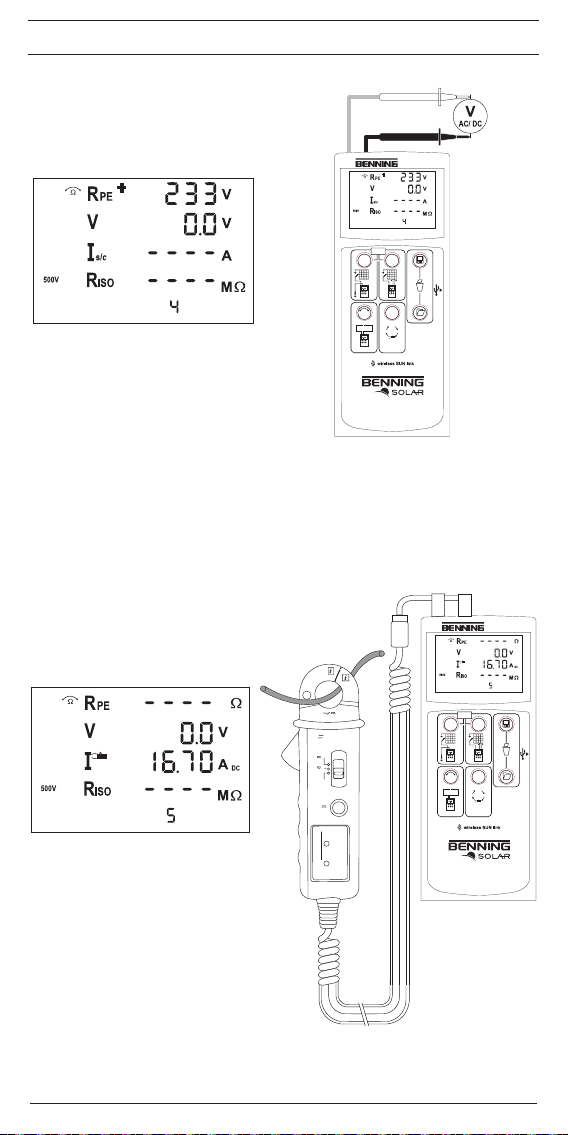
Bild 7: Spannungsmessung über 4 mm Prüfbuchsen
Fig. 7: Voltage measurement via 4 mm test sockets
NULL
Bild 8: AC/ DC-Strommessung mit optionalem
Stromzangenadapter BENNING CC 3
Fig. 8: AC/ DC current measurement by means
of optional current clamp adapter
BENNING CC 3
PV 1-1
NULL
ON/OFF
press 2 sec.
Auto
R
PE
Ω
V
ISO
NULL
500V
250V 1000V
DIN EN 62446 (VDE 0126-23), ÖVE/ÖNORM EN 62446
PV 1-1
NULL
NULL
09/ 2012
+
300A
CAT. III 600V
300A
40A
OFF
ZERO A
BENNING CC 3
BATT
LOW
300A : 1mV/A
PWR
ON
BENNING PV 1-1
ON/OFF
press 2 sec.
Auto
R
PE
Ω
V
ISO
NULL
500V
250V 1000V
40A : 10mV/A
DIN EN 62446 (VDE 0126-23), ÖVE/ÖNORM EN 62446
Page 6
D
PV 1-1
T
PV
T
A
SUN 2
Bild 9: Funkverbindung zum optionalen Einstrahlungs- und Temperaturmessgerät BENNING SUN 2
Fig. 9: Radio connection to the optional insolation and temperature measuring instrument BENNING SUN 2
c
Max.
P ≤ 10 kW
Vo/c ≤ 1000 V
Is/c ≤ 15 A
PV-Modul/ -Strang
PV-module/ -string
PV 1-1
ON/OFF
press 2 sec.
Auto
R
PE
Ω
V
ISO
NULL
500V
250V 1000V
DIN EN 62446 (VDE 0126-23), ÖVE/ÖNORM EN 62446
T
PV
T
A
SUN 2
OK
HOLD
ON/OFF
LOG
Bild 10: Batterie-/ Sicherungswechsel
Fig. 10: Battery/ fuse replacement
09/ 2012
BENNING PV 1-1
Page 7
D
Bedienungsanleitung
BENNING PV 1-1
Batteriebetriebener Photovoltaiktester für die Installations- und Wiederholungsprüfung von netzgekoppelten Photovoltaik-Systemen gemäß VDE 0126-23 (DIN EN 62446).
- Schutzleiterwiderstandsmessung mit 200 mA DC Prüfstrom
- Automatische Anzeige der Spannungspolarität mit akustischer/visueller Warnung bei
Falschpolung
- Leerlaufspannungsmessung am PV-Modul/PV-Strang bis 1.000 V DC
- Kurzschlussstrommessung am PV-Modul/PV-Strang bis 15 A DC
- Isolationswiderstandsmessung mit Prüfspannung 250 V, 500 V, 1.000 V DC
-
Funktionstest durch Strommessung mittels optionalem Stromzangenadapter BENNING CC 3
bis 40 AAC/DC.
- Messung der solaren Einstrahlung, PV-Modul- und Umgebungstemperatur mittels optionalem Einstrahlungs- und Temperaturmessgerät BENNING SUN 2.
Inhaltsverzeichnis
1. Benutzerhinweise
2. Sicherheitshinweise
3. Lieferumfang
4. Gerätebeschreibung
5. Allgemeine Angaben
6. Umgebungsbedingungen
7. Elektrische Angaben
8. Prüfen mit dem BENNING PV 1-1
9. Instandhaltung
10. Umweltschutz
1. Benutzerhinweise
Diese Bedienungsanleitung ist für ausgebildetes Fachpersonal geschrieben!
Qualifiziertes Personal ist befähigt Risiken zu erkennen und mögliche Gefähr-
m
dungen zu vermeiden. Es besteht Verletzungsgefahr durch unsachgemäße
Handhabung!
Warnung vor gefährlicher elektrischer Spannung!
c
Beachten Sie unbedingt alle Sicherheitshinweise!
Internationale, nationale und gegebenenfalls regionale Vorschriften der Elektrotechnik sind in
jedem Fall einzuhalten. Einschlägige Kenntnisse der Elektrotechnik werden vorausgesetzt.
Das BENNING PV 1-1 ist zur Messung in trockener Umgebung vorgesehen (näheres hierzu im
Abschnitt 6: Umgebungsbedingungen).
In der Bedienungsanleitung und auf dem BENNING PV 1-1 werden folgende Symbole verwendet:
Warnung vor elektrischer Gefahr!
Steht vor Hinweisen, die beachtet werden müssen, um Gefahren für Menschen zu
c
vermeiden.
Achtung Dokumentation beachten!
Das Symbol gibt an, dass die Hinweise in der Bedienungsanleitung zu beachten
m
sind, um Gefahren zu vermeiden.
Dieses Symbol auf dem BENNING PV 1-1 bedeutet, dass das BENNING PV 1-1
konform zu den EU-Richtlinien ist.
Dieses Symbol erscheint in der Anzeige für entladene Batterien. Sobald das
Batteriesymbol blinkt, tauschen Sie umgehend die Batterien gegen neue Batterien aus.
Symbolisiert ein PV-Modul/ PV-Strang
(AC) Wechsel-Spannung oder -Strom.
(DC) Gleich-Spannung oder -Strom.
Erde (Spannung gegen Erde).
Schutzklasse I
Schutzklasse II
09/ 2012
BENNING PV 1-1
1
Page 8

D
2. Sicherheitshinweise
Das Gerät ist gemäß
DIN VDE 0411 Teil 1/ EN 61010 Teil 1
DIN VDE 0413 Teil 1/ EN 61557 Teil 1, 2, 4 und 10
gebaut und geprüft und hat das Werk in einem sicherheitstechnisch einwandfreien Zustand verlassen. Um diesen Zustand zu erhalten und einen gefahrlosen Betrieb sicherzustellen, muss
der Anwender die Hinweise und Warnvermerke beachten, die in dieser Anleitung enthalten sind.
Fehlverhalten und Nichtbeachtung der Warnungen kann zu schwerwiegenden Verletzungen
oder zum Tode führen.
Der Anschluss an den PV-Generator ist ausschließlich gemäß den
Anschlussbildern der Bedienungsanleitung vorzunehmen.
c
Nicht benötigte Sicherheitsmessleitungen sind von dem BENNING PV 1-1 zu
trennen.
Der PV-Generator darf die maximale Leerlaufspannung von 1000 V, den
maximalen Kurzschlussstrom von 15 A und die maximale DC-Leistung
(P = U x I) von 10 kW nicht überschreiten.
c
Gemäß DIN EN 62446 sind die Messungen pro PV-Strang durchzuführen!
Eine Messung an parallel geschalteten PV-Strängen kann zur Beschädigung
des BENNING PV 1-1 führen!
Die PV-Prüfbuchsen 9 und J sind ausschließlich für die Kontaktierung mit
c
PV-Generatoren (PV-Modul, PV-Strang) vorgesehen.
Das Prüfgerät BENNING PV 1-1 direkt nach beendeter Prüfung vom PV-Generator
c
trennen.
Messspitzen nicht berühren!
Bei Isolationswiderstandsmessungen können hohe elektrische Spannungen an
c
den Messspitzen anliegen.
Während der Messung keine Metallteile des Prüfobjektes berühren.
c
Der PV-Generator muss von der elektrischen Hauptversorgung isoliert sein!
c
Weder Plus- noch Minuspol des PV-Generators darf geerdet sein!
Über die 4 mm Sicherheitsmessleitungen sind Spannungsmessungen an
Steckdosenstromkreise möglich. Das BENNING PV 1-1 darf über die 4 mm
Prüfbuchsen K und L nur in Stromkreisen der Überspannungskategorie III mit
c
max. 300 V AC/DC Leiter gegen Erde benutzt werden. Bei Spannungsmessungen über die 4 mm Prüf buchsen K und L sind vorher die PV-Sicherheitsmessleitungen von den PV-Prüfbuchsen 9 und J zu trennen.
Extreme Vorsicht bei Arbeiten um blanke Leiter oder Hauptleitungsträger. Ein
Kontakt mit Leitern kann einen Elektroschock verursachen.
Beachten Sie, dass Arbeiten an spannungsführenden Teilen und Anlagen
c
grundsätzlich gefährlich sind. Bereits Spannungen ab 30 V AC und 60 V DC
können für den Menschen lebensgefährlich sein.
Vor jeder Inbetriebnahme überprüfen Sie das Gerät und die Leitungen auf Beschädigungen. Ein beschädigtes BENNING PV 1-1 nicht verwenden! Beschä-
c
digte Sicherheitsmessleitungen ersetzen!
Verwenden Sie ausschließlich, die im Lieferumfang des BENNING PV 1-1
c
enthaltenen Sicherheitsmessleitungen.
Das Prüfgerät BENNING PV 1-1 ausschließlich gemäß der in dieser Dokumenta-
c
tion angegebenen, bestimmungsgemäßen Verwendung einsetzen.
Das BENNING PV 1-1 nur in trockener Umgebung verwenden.
c
Ist anzunehmen, dass ein gefahrloser Betrieb nicht mehr möglich ist, ist das Gerät außer Betrieb
zu setzen und gegen unbeabsichtigten Betrieb zu sichern.
09/ 2012
BENNING PV 1-1
2
Page 9

D
Es ist anzunehmen, dass ein gefahrloser Betrieb nicht mehr möglich ist,
- wenn das Gerät oder die Sicherheitsmessleitungen sichtbare Beschädigungen aufweisen,
- wenn das Gerät nicht mehr arbeitet,
- nach längerer Lagerung unter ungünstigen Verhältnissen,
- nach schweren Transportbeanspruchungen,
- wenn das Gerät oder die Sicherheitsmessleitungen feucht sind.
Um eine Gefährdung auszuschließen
- berühren Sie die Leitungen nicht an den blanken Messspitzen,
c
- stecken Sie die Leitungen in die entsprechend gekennzeichneten Buchsen
am Messinstrument
Wartung:
Das Gerät nicht öffnen, es enthält keine durch den Benutzer wartbaren Kompo-
c
nenten. Reparatur und Service kann nur durch qualifiziertes Personal erfolgen.
Reinigung:
Das Gehäuse regelmäßig mit einem Tuch und Reinigungsmittel trocken
m
abwischen. Kein Poliermittel oder Lösungsmittel verwenden.
3. Lieferumfang
Zum Lieferumfang des BENNING PV 1-1 gehören:
3.1 ein Stück BENNING PV 1-1
3.2 ein Stück Transport-/ Aufbewahrungstasche
3.3 zwei Stück Sicherheitsmessleitungen mit Prüfspitze (L = 1,2 m) (rot/ schwarz)
3.4 zwei Stück Sicherheitskrokodilklemmen (rot/ schwarz)
3.5 zwei Stück Sicherheitsmessleitungen für MC4-Steckverbinder (rot/ schwarz)
3.6 zwei Stück Sicherheitsmessleitungen für „Sunclix“-Steckverbinder (rot/ schwarz)
3.7 ein Stück USB-Verbindungskabel (A-Stecker auf Micro-B-Stecker)
3.8 sechs Stück 1,5 V Mignon-Batterien/ Typ AA, IEC LR6
3.9 ein Stück Kurzanleitung
3.10
ein Stück CD-ROM mit Download-/Treiber-Software, ausführlicher mehrsprachiger Be-
dienungsanleitung und Informationsmaterial
Hinweis auf Verschleißteile:
- Das BENNING PV 1-1 enthält eine Sicherung zum Überlastschutz:
Ein Stück Sicherung Nennstrom 500 mA, F, 1000 V, Trennvermögen ≥ 1000 A, D = 6,3 mm,
L = 32 mm (T.Nr. 749771)
- Das BENNING PV 1-1 benötigt sechs 1,5 V Mignon-Batterien/ Typ AA, IEC LR6
Hinweis auf optionales Zubehör:
- AC/ DC-Stromzangenadapter BENNING CC 3 zum Anschluss an das BENNING PV 1-1. Die
gemessenen AC/ DC-Stromwerte können in dem Speicher des BENNING PV 1-1 abgelegt
und wieder aufgerufen werden (T.Nr. 044038).
- Einstrahlungs- und Temperaturmessgerät BENNING SUN 2 zur Messung der solaren Einstrahlung (W/m²), der PV-Modul- und Umgebungstemperatur. (T.Nr: 050420)
- 40 m Messleitung BENNING TA 5 mit praktischem Aufwickler und Handschlaufe. Anschluss:
4 mm Sicherheitsprüfbuchse/ -stecker (T.Nr. 044039).
- Prüfplaketten „Nächster Prüftermin“, 300 Stück (T.Nr. 756212)
- Prüfprotokoll-Formulare “Prüfung von PV-Anlagen” können Sie kostenlos downloaden un ter
www.benning.de
4. Gerätebeschreibung
siehe Bild 1: Gerätefrontseite
siehe Bild 2: Geräteoberseite
siehe Bild 3: Digitalanzeige
Die in Bild 1, 2 und 3 angegebenen Anzeige- und Bedienelemente werden wie folgt bezeichnet:
1
Digitalanzeige, zeigt den Prüffortschritt und einzelne Messergebnisse,
R
PE
2
-Taste, Prüfung des Schutzleiterwiderstandes
Auto
3
-Taste, startet den automatischen PV-Prüfablauf nach VDE 0126-23 (DIN EN 62446)
Ω
4
NULL
-Taste, zum Nullabgleich der Messleitungswiderstände
V
5
ISO
-Taste, Auswahl der Prüfspannung für die Isolationswiderstandsmessung
6
-Taste, zum Aufrufen gespeicherter Messwerte (Displaywerte)
7
USB-Schnittstelle (Micro-B-Buchse), zum Anschluss des USB-Verbindungskabels
8
-Taste, zur Speicherung der angezeigten Messwerte (Displaywerte)
9
+ PV-Prüfbuchse (rot), zum Anschluss der roten Sicherheitsmessleitung mit PV-Steckverbinder
J
– PV-Prüfbuchse (schwarz), zum Anschluss der schwarzen Sicherheitsmessleitung mit PV-
09/ 2012
BENNING PV 1-1
3
Page 10

D
Ω
Steckverbinder
K – 4 mm Prüfbuchse (schwarz), zum Anschluss der Sicherheitsmessleitung mit Prüfspitze/
Krokodilklemme
L + 4 mm Prüfbuchse (rot), zum Anschluss der Sicherheitsmessleitung mit Prüfspitze/ Kro-
kodilklemme
A RPE Spannungs-Polaritätsanzeige, zeigt die Polarität der DC-Spannung an den 4 mm
Prüfbuchsen K und L an. Bei Wechselspannung wird abwechselnd "+" und "–" angezeigt.
B Stromzangen-Messung aktiv.
C
RPE (Null-Offset), erscheint bei Kompensation (Nullabgleich) des Messleitungswider-
NULL
standes.
D
(Achtung, heiße Oberfläche), bei aktiviertem Symbol, das BENNING PV 1-1 sofort von
dem PV-Generator trennen. Erst nach Erlöschen des Symbols das BENNING PV 1-1 anschließen.
E (Polaritätsanzeige)
und J an.
F c (Achtung, gefährliche Spannung) festgestellt.
G (RPE LOCK) (Feststellung), aktiv, wenn eine kontinuierliche RPE Messung aktiviert wurde.
H m (Achtung), bei aktiviertem Symbol Anweisungen in der Bedienungsanleitung beachten,
um Gefahren zu vermeiden.
I R
(gut)/ (schlecht), zeigt an, ob der gemessene Isolationswiderstand innerhalb der
ISO
voreingestellten Grenzwerte liegt.
J Auswahl der Isolationsprüfspannung, zeigt die Prüfspannung der Isolationswiderstands-
messung an.
K Error (Fehler), siehe spezifische Fehlercodes, (näheres hierzu im Abschnitt 9.1 Fehler-
codes) für weitere Details.
L STORE, LCD-Daten werden im internen Speicher gespeichert.
M RECALL, gespeicherte LCD-Daten wurden aus dem internen Speicher geladen.
N Speicherplatzanzeige, zeigt den aktuellen Speicherplatz (1…200) an.
O Spannung/ Strom Abweichung, zeigt eine Abweichung der gemessenen Leerlaufspan-
nungs- und Kurzschlussstromwerte größer oder kleiner als 5% an.
P Batteriesymbol, erscheint bei entladenen Batterien
5. Allgemeine Angaben
Das BENNING PV 1-1 führt elektrische Sicherheitsüberprüfungen nach VDE 0126-23 (DIN EN
62446) aus.
Eigenständig überprüft das BENNING PV 1-1 angeschlossene PV-Module oder PV-Stränge. Alle
Messergebnisse werden auf das große LCD-Display ausgegeben.
- Bei voller Batteriekapazität ermöglicht das BENNING PV 1-1 eine Anzahl von bis zu 3000
automatische Messungen von Vo/c, Is/c und R
- Geräteabmessungen:
(L x B x H) = 270 x 115 x 55 mm
- Gerätegewicht: 2600 g
6. Umgebungsbedingungen
- Das BENNING PV 1-1 ist für Messungen in trockener Umgebung vorgesehen.
- Barometrische Höhe bei Messungen: 0 m bis maximal 2000 m
- Überspannungskategorie/ Aufstellungskategorie: IEC/ EN 61010-1 → 1000 V Kategorie I
(gilt nur für die rote 9 und schwarze J PV-Prüfbuchse),
- Überspannungskategorie/ Aufstellungskategorie: IEC/ EN 61010-1 → 300 V Kategorie III
(gilt nur für die rote L und schwarze K 4 mm Prüfbuchse),
- Verschmutzungsgrad: 2
- Schutzart: IP 50 (DIN VDE 0470-1, IEC/ EN 60529)
5 - erste Kennziffer: Staubgeschützt
0 - zweite Kennziffer: Kein Schutz gegen Wasser
- EMC: IEC/ EN 61326,
- Arbeitstemperatur und relative Luftfeuchte:
Bei Arbeitstemperatur von 0 °C bis 30 °C: relative Luftfeuchte kleiner 80 %,
Bei Arbeitstemperatur von 31 °C bis 40 °C: relative Luftfeuchte kleiner 75 %,
-
Lagerungstemperatur: Das BENNING PV 1-1 kann bei Temperaturen von - 25 °C bis + 65 °C
(Luftfeuchte 0 bis 90 %) gelagert werden. Dabei sind die Batterien aus dem Gerät herauszuneh-
men.
7. Elektrische Angaben
Bemerkung: Die Messgenauigkeit wird angegeben als Summe aus
- einem relativen Anteil des Messwertes und
- einer Anzahl von Digit (d.h. Zahlenschritte der letzten Stelle).
Diese Messgenauigkeit gilt bei Temperaturen von 18 °C bis 30 °C und einer relativen Luftfeuchtigkeit kleiner 80 %.
, zeigt die Polarität der DC-Spannung an den PV-Prüfbuchsen 9
(500V).
ISO
09/ 2012
BENNING PV 1-1
4
Page 11

D
7.1 Schutzleiterwiderstand R
PE
Messbereich Auflösung Messgenauigkeit
0,05 Ω - 199 Ω 0,01 Ω Maximum ± (2 % + 2 Digit)
Prüfstrom: > 200 mA (2 Ω)
Leerlaufspannung: > 4 V
Anzahl der
Wiederholungsprüfungen
(IEC 61557-2)
ca. 4000
7.2 PV-Modul/ PV-Strang, Leerlaufspannung, Vo/c
Messbereich Auflösung Messgenauigkeit
5,0 V - 1000 V 0,1 V ± (0,5 % + 2 Digit)
7.3 PV-Modul/ PV-Strang, Kurzschlussstrom, Is/c
Messbereich Auflösung Messgenauigkeit
0,50 A - 14,99 A 0,01 A ± (1 % + 2 Digit)
7.4 Isolationswiderstand, R
ISO
Messbereich Auflösung Messgenauigkeit
0,20 MΩ - 100 MΩ max. 0,01 MΩ ± (5 % + 5 Digit)
101 MΩ - 199 MΩ 1 MΩ ± (10 % + 5 Digit)
Prüfspannung
Prüfstrom
Anzahl der
Wiederholungsprüfungen
(IEC 61557-2)
:
250 VDC/ 500 VDC/ 1000 VDC, + 20 %, - 0 %
: > 1 mA, < 2 mA bei Kurzschluss
ca. 2000
7.5 RPE Spannung über 4 mm Prüfbuchsen
Messbereich Auflösung
Messgenauigkeit
(DC, AC 50 Hz - 60 Hz)
30 V - 440 V AC/ DC 1 V ± (5 % + 2 Digit)
7.6 Strom mit AC/ DC Stromzangenadapter BENNING CC 3 (T.Nr. 044038)
Messbereich Auflösung
Messgenauigkeit
(DC, AC 50 Hz - 60 Hz)
0,1 A - 40,0 A AC/ DC 0,1 A ± (5 % + 2 Digit)
8. Prüfen mit dem BENNING PV 1-1
8.1 Vorbereiten der Prüfung
Benutzen und lagern Sie das BENNING PV 1-1 nur bei den angegebenen Lager- und Arbeitstemperaturbedingungen, vermeiden Sie dauernde Sonneneinstrahlung.
-
Angaben von Nennspannung und Nennstrom auf den Sicherheitsmessleitungen überprüfen.
- Starke Störquellen in der Nähe des BENNING PV 1-1 können zu instabiler Anzeige und zu
Messfehlern führen.
Vor jeder Inbetriebnahme überprüfen Sie das Gerät, die Leitungen und das
m
Prüfobjekt auf Beschädigungen.
8.1.1 Ein-, Ausschalten des BENNING PV 1-1
- Durch gleichzeitiges Betätigen der
das BENNING PV 1-1 eingeschaltet, Signaltöne bestätigen dies. Erneutes Drücken der Tasten für > 2 Sekunden schaltet das Gerät aus.
- Das BENNING PV 1-1 schaltet sich nach ca. 1 Minute selbstständig ab. (APO, Auto-Power-
Off). Es schaltet sich wieder ein, wenn die
09/ 2012
R
PE
-Taste 2 und
BENNING PV 1-1
R
PE
-Taste 2 und
Auto
-Taste 3 für ca. 2 Sekunden wird
Auto
-Taste 3 betätigt werden.
5
Page 12

D
Ein Signalton signalisiert die Abschaltung des Gerätes.
8.1.2 Einstellen der automatischen Abschaltzeit (APO, Auto-Power Off)
- Schalten Sie das BENNING PV 1-1 durch gleichzeitiges Betätigen der
Auto
-Taste 3 aus.
- Drücken und halten Sie die
Auto
und
- Das LCD-Display 1 zeigt in der ersten Zeile „OFF“ und in der zweiten Zeile die Abschaltzeit
- Jede Betätigung der
- Lassen Sie die
8.1.3 Einstellen von Datum und Uhrzeit
Das BENNING PV 1-1 verfügt über eine integrierte Echtzeituhr um jeden Speichervorgang
bzw. Speicherplatz automatisch ein Datum-/Zeitstempel hinzuzufügen (siehe Abschnitt 8.7
Messwertspeicher).
Für die Einstellung von Datum und Uhrzeit führen Sie folgende Schritte aus:
- Schalten Sie das BENNING PV 1-1 durch gleichzeitiges Betätigen der
- Drücken und halten Sie die -Taste 6 und betätigen Sie gleichzeitig die
- Das Datum-/Uhrzeitformat wird wie folgt angezeigt:
MM.DD = Monat (1-12).Tag (1-31)
YYYY = Jahr
HH.mm = Stunden (0-23).Minuten (0-59)
SS = Sekunden (0-59)
- Drücken Sie die
- Ein blinkendes Feld verdeutlicht, dass dieses Feld eingestellt werden kann.
- Über die -Taste 8 und die -Taste 6 wird der Wert erhöht bzw. verringert.
Mit jeder Änderung wird das Sekundenfeld auf Null gesetzt.
- Schalten Sie das Gerät durch gleichzeitiges Betätigen der
8.1.4 Prüfung des Batteriezustandes
Das BENNING PV 1-1 führt während des Einschaltens und im laufenden Betrieb einen automatischen Batterietest durch. Entladene Batterien werden durch ein Batteriesymbol P im LCD-Display 1 dargestellt. Sobald das Batteriesymbol blinkt sind die Batterien umgehend zu ersetzen
(siehe Abschnitt 9.4, „Batteriewechsel“).
8.1.5 Kompensation der Sicherheitsmessleitungen (Nullabgleich)
Um eine Kompensation (Nullabgleich) des Messleitungswiderstandes durchzuführen, kontaktieren Sie die Sicherheitsmessleitungen über die Sicherheitskrokodilklemmen miteinander und
drücken die
-Taste 3. Halten Sie die
in Minuten an.
Minuten.
Auto
-Taste 3 aus.
Auto
-Taste 3.
Ω
NULL
-Taste 4 los um die Einstellung zu speichern.
R
PE
aus, um die Einstellung zu speichern.
Ω
NULL
-Taste 4 bis das Symbol
Messleitungswiderstände können bis 10 Ohm kompensiert werden.
m
Ω
NULL
-Taste 4 und betätigen Sie gleichzeitig die
Ω
NULL
-Taste 4 weiter gedrückt.
V
ISO
-Taste 5 erhöht die Abschaltzeit um eine Minute bis maximal 10
-Taste 2 um ein Datum/ Uhrzeitfeld anzuwählen.
R
PE
Ω
C im LCD-Display 1 erscheint.
NULL
siehe Bild 4: Nullabgleich der Sicherheitsmessleitung für RPE-Messung
8.2 Prüfung des Schutzleiterwiderstandes, R
Weder Plus- noch Minuspol des PV-Generators darf geerdet sein!
m
Bei Anliegen einer Spannung von > 30 V am Prüfobjekt wird die ermittelte
Spannung angezeigt. Steigt die Messspannung an den Prüfspitzen über 30 V
wird die RPE-Messung blockiert! Wird die RPE-Messung unterhalb von 30 V
m
gestartet, kann eine niederohmige Spannungsquelle die eingebaute Sicherung
im BENNING PV 1-1 auslösen!
Zur Einzelmessung:
- Schalten Sie den Schaltkreis bzw. das Prüfobjekt spannungsfrei.
- Schließen Sie die rote und schwarze Sicherheitsmessleitung an die jeweilige 4 mm Prüfbuchse L und K an und kontaktieren Sie das Prüfobjekt.
- Drücken Sie die
- Der gemessene Schutzleiterwiderstand RPE wird im Display 1 angezeigt.
siehe Bild 5: Prüfung des Schutzleiterwiderstandes R
Zur fortlaufenden Messung:
- Schalten Sie den Schaltkreis bzw. das Prüfobjekt spannungsfrei.
- Schließen Sie die rote und schwarze Sicherheitsmessleitung an die jeweilige 4 mm Prüfbuchse L und K an und kontaktieren Sie das Prüfobjekt.
- Drücken und halten Sie die
- Der gemessene Schutzleiterwiderstand RPE wird fortlaufend im Display 1 angezeigt.
09/ 2012
R
PE
-Taste 2.
R
PE
-Taste 2 gedrückt bis das Symbol G erscheint.
BENNING PV 1-1
PE
PE
R
PE
R
PE
R
-Taste 2 und
-Taste 2 und
R
PE
-Taste 2
-Taste 2 und
PE
-Taste 2 und
Auto
-Taste 3
6
Page 13

D
R
- Zum Beenden der fortlaufenden Messung drücken Sie die
siehe Bild 5: Prüfung des Schutzleiterwiderstandes R
8.3 Automatische Messung von Leerlaufspannung, Kurzschlussstrom und Isolations-
widerstand des PV-Generators
Der PV-Generator darf die maximale Leerlaufspannung von 1000 V, den maximalen Kurzschlussstrom von 15 A und die maximale DC-Leistung (P = U x I)
von 10 kW nicht überschreiten.
c
Gemäß DIN EN 62446 sind die Messungen pro PV-Strang durchzuführen!
Eine Messung an parallel geschalteten PV-Strängen kann zur Überlastung des
BENNING PV 1-1 führen!
Der PV-Generator muss von der elektrischen Hauptversorgung isoliert sein!
c
Weder Plus- noch Minuspol des PV-Generators darf geerdet sein!
Während der Isolationswiderstandsmessung wird der PV-Generator kurzgeschlossen. Die Messung erfolgt zwischen der roten 4 mm Prüfbuchse und den
m
kurzgeschlossenen PV-Prüfbuchsen.
Falls die DC-Polarität fehlerhaft ist oder die DC-Spannung im Bereich von < 5 V
m
bzw. > 1000 V liegt, ist keine automatische PV-Messung möglich.
- Verbinden Sie das BENNING PV 1-1 über die mitgelieferten PV-Sicherheitsmessleitungen
mit dem PV-Modul bzw. dem PV-Strang.
-
Für die Isolationswiderstandsmessung verbinden Sie die rote Sicherheitsmessleitung der
4 mm Prüfbuchse L mit einem Metallteil (Rahmen oder Montagesystem) des PV-Generators.
- Ist der PV-Generator ordnungsgemäß über einen Erdungsleiter geerdet, kann alternativ die
rote Sicherheitsmessleitung der 4 mm Prüfbuchse L mit einer sicheren Erdverbindung (Po-
tentialausgleichsschiene) kontaktiert werden.
- Die Messung der PV-Leerlaufspannung erfolgt automatisch bei anliegender DC-Spannung
an den PV-Sicherheitsmessleitungen (Prüfbuchsen 9 und J).
- Bei Verpolung der DC-Spannung blinkt die Polaritätsanzeige und das Symbol E wird
eingeblendet. Die automatische Messung bleibt solange gesperrt bis die Polarität der DCSpannung korrekt ist.
- Sobald eine Spannung von > 30 V an den PV-Sicherheitsmessleitungen anliegt, blinkt das
Warnsymbol c F (Achtung, gefährliche Spannung).
- Zur Einstellung der Prüfspannung für die Isolationswiderstandsmessung drücken Sie die
-Taste 5 und wählen die gewünschte Prüfspannung aus (250 V, 500 V oder 1000 V DC).
- Drücken Sie die
sungen werden durchgeführt:
- Messung der PV-Leerlaufspannung
- Messung des PV-Kurzschlussstromes
- Messung des Isolationswiderstandes
- Die Messwerte werden für ca. 20 Sekunden oder bis zu einem Tastendruck im Display 1
dargestellt.
- Liegt der gemessene Isolationswiderstand oberhalb der voreingestellten Grenzwerte, erscheint neben dem Isolationswiderstandswert das Symbol . Liegt der Isolationswiderstandswert unterhalb der Grenzwerte erscheint das Symbol .
siehe Bild 6: Automatische Solarmodul-Messung, ISO-Messung über Erdleiter
Voreingestellte Grenzwerte:
Auto
-Taste 3 zum Starten der automatischen PV-Messung. Folgende Mes-
V
ISO
250 V 0,5 MΩ
500 V 1,0 MΩ
1000 V 1,0 MΩ
PE
-Taste 2.
PE
Grenzwert Isolationswiderstand
V
ISO
8.4 Gleich- und Wechselspannungsmessung
- Entfernen Sie die PV-Sicherheitsmessleitungen von den PV-Prüfbuchsen 9 und J.
-
Schließen Sie die rote und schwarze Sicherheitsmessleitung an die jeweilige 4 mm Prüfbuchse
K
und
L an.
- Verbinden Sie die Messspitzen mit der zu messenden Spannungsquelle.
- Das BENNING PV 1-1 misst automatisch die Spannung an den Messspitzen.
- Die Polarität der Gleichspannung (DC) wird mit "+ / -" A gekennzeichnet. Bei Wechselspannung (AC) wird "+ / -" A im Wechsel angezeigt.
siehe Bild 7: Spannungsmessung über 4 mm Prüfbuchsen
09/ 2012
BENNING PV 1-1
7
Page 14

D
8.5
Strommessung mit optionalem AC/ DC-Stromzangenadapter BENNING CC 3 (T.Nr. 044038)
Das BENNING PV 1-1 kann mit dem optionalen AC/ DC-Stromzangenadapter BENNING CC 3
den Betriebsstrom einer PV-Anlage messen. Die ermittelten Stromwerte können in dem internen
Speicher des BENNING PV 1-1 abgelegt und wieder aufgerufen werden.
- Entfernen Sie alle Sicherheitsmessleitungen vom BENNING PV 1-1.
- Schließen Sie den Stromzangenadapter BENNING CC 3 an die 4 mm Prüfbuchsen K und
L des BENNING PV 1-1 an
-
Schalten Sie den Stromzangenadapter BENNING CC 3 ein und wählen Sie den 40 A-Bereich.
- Schalten Sie das BENNING PV 1-1 ein und betätigen Sie die
B für die Stromzangenmessung erscheint.
- Für Gleichstrommessungen (DC) drücken Sie die Nullabgleichstaste (ZERO) am
BENNING CC 3 bis ein Stromwert von ca. 0 A angezeigt wird.
- Legen Sie den Stromzangenadapter um den einadrigen, stromdurchflossenen Leiter.
- Der gemessene Strom wird im Display 1 angezeigt.
siehe Bild 8:
8.6 Messung an mehreren identischen PV-Modulen/ PV-Strängen
Bei PV-Systemen mit mehreren identischen PV-Strängen müssen die Leerlaufspannungen und
die Kurzschlussströme bei stabilen Bestrahlungsbedingungen miteinander verglichen werden.
Die Werte sollten identisch sein und innerhalb einer maximalen Abweichung von 5 % liegen (bei
stabilen Bestrahlungsbedingungen). Ferner sind die gemessenen Werte mit den zu erwartenden
Werten zu vergleichen.
- Zu Beginn der Messreihe die -Taste 8 und -Taste 6 gedrückt halten, um den Messwertspeicher zu löschen.
- Verbinden Sie den ersten PV-Strang des PV-Generators mit dem BENNING PV 1-1.
Auto
-
- -Taste 8 drücken, um die Messwerte zu speichern.
- Verbinden Sie den nächsten PV-Strang mit dem BENNING PV 1-1 und drücken Sie die
-Taste 3 zum Start der automatischen Messung.
- -Taste 8 drücken, um die Messwerte zu speichern.
- Wiederholen Sie diesen Vorgang für alle identischen PV-Stränge und bei stabilen Strah-
lungsbedingungen.
- Nach Abschluss der Prüfung können über die -Taste 6 die gespeicherten Messwerte
aufgerufen werden. Sobald ein Messwert um mehr als 5 % vom Mittelwert der Leerlaufspannung oder des Kurzschlussstromes aller gespeicherten Messwerte abweicht, blinkt das
">5%" Symbol O.
- Zum Aufrufen der Mittelwerte drücken Sie die -Taste 6 wiederholt bis der Speicherplatz 0
erscheint. Der Mittelwert der Leerlaufspannung und des Kurzschlussstromes wird im Display
1
siehe Bild 6: Automatische Solarmodul-Messung, ISO-Messung über Erdleiter
8.7 Messwertspeicher
8.7.1 Messwerte speichern
Das BENNING PV 1-1 kann bis zu 200 Displayanzeigen speichern. Abhängig der durchgeführten Messungen werden pro Speicherplatz der Schutzleiterwiderstand, die Leerlaufspannung,
der Kurzschlussstrom, der Isolationswiderstand mit Prüfspannung oder auch der gemessene
AC/ DC-Strom (BENNING CC 3) mit einem Datum-/ Zeitstempel gespeichert.
- Drücken Sie die -Taste 8, um die angezeigten Messwerte im ersten freien Speicherplatz
zu speichern. Eine erfolgreiche Speicherung wird mit dem Symbol "STORE" L im LCDDisplay 1 bestätigt.
8.7.2 Messwerte aufrufen
- Drücken Sie die -Taste 6, um die gespeicherten Messwerte mit der zugehörigen Speicherplatznummer N wieder aufzurufen. Das Symbol "RECALL" M erscheint im Display 1.
Die Speicherplatznummer N wird im Display 1 dargestellt.
- Durch erneutes Drücken der -Taste 6 wird zum nächsten Speicherplatz gewechselt.
- Durch Drücken der -Taste 8 kann zum vorherigen Speicherplatz gewechselt werden.
8.7.3 Messwertspeicher löschen
-
Zum Löschen des kompletten Messwertspeichers die -Taste 8 und -Taste 6 drücken.
8.7.4 Warnung bei 5% Abweichung des Messwertes
-
Bei einer 5 %-Abweichung des angezeigten Messwertspeichers (Leerlaufspannung und Kurzschlussstrom) zum Mittelwert über alle gespeicherten Messwerte, blinkt das "5%"-Symbol.
8.7.5 Mittelwert der Leerlaufspannung und des Kurzschlussstromes des gesamten Messwert-
-
Drücken Sie die
Symbol "RECALL" M erscheint im Display 1.
- Der Speicherplatz 0 N berechnet die Mittelwerte von Leerlaufspannung und Kurzschluss-
strom aller gespeicherten Messwerte.
AC/ DC-Strommessung mit optionalem Stromzangenadapter BENNING CC 3
-Taste 3 drücken, zur automatischen Messung des ersten PV-Strangs.
angezeigt.
speichers
-Taste
6 wiederholt bis im Display 1 der Speicherplatz 0 N erscheint. Das
8.7.6 Messwertspeicher über USB-Schnittstelle auslesen
09/ 2012
BENNING PV 1-1
V
ISO
-Taste 5 bis das Symbol
Auto
8
Page 15

D
Um die Messwerte über die USB-Schnittstelle 7 auszulesen, müssen Sie einmalig von der beiliegenden CD-ROM den Hardwaretreiber aus dem Verzeichnis „Treiber-driver“ und anschließend
das Downloadprogramm aus dem Verzeichnis „Programm-program“ auf Ihrem PC installieren.
Für den Datendownload führen Sie folgende Schritte aus:
- Entfernen Sie alle Sicherheitsmessleitungen vom BENNING PV 1-1.
- Verbinden Sie das BENNING PV 1-1 über das USB-Verbindungskabel mit dem PC.
- Der Hardwaretreiber installiert sich auf einem freien COM-Port und bestätigt sobald die neue
Hardware benutzt werden kann.
- Der verwendete COM-Port ist über den Geräte-Manager Ihres Systems ersichtlich.
- Starten Sie das Programm „BENNING SOLAR Datalogger“, klicken Sie unter Optionen auf
„COM-Ports aktualisieren" und wählen den entsprechenden COM-Port aus. Klicken Sie
anschließend auf „Download“.
- Drücken Sie am BENNING PV 1-1 die -Taste 6 für ca. 2 Sek. bis der Download erfolgt
und der komplette Messwertspeicher ausgelesen wird.
- Die Messwerte können als (*.csv) oder (*.txt)-Datei gespeichert werden.
- Durch Klicken auf „Öffnen“ kann die Messreihe z. B. über ein Tabellenkalkulationsprogramm
geöffnet werden.
8.8 Funkverbindung zu BENNING SUN 2 - Wireless SUN link
Das BENNING PV 1-1 kann die Messwerte (Solare Einstrahlung, PV-Modul-/ Umgebungstemperatur und Datum-/ Zeitstempel) des Einstrahlungs- und Temperaturmessgerätes
BENNING SUN 2 (Option) per Funk empfangen.
Hierzu muss einmalig das BENNING PV 1-1 mit dem BENNING SUN 2 gekoppelt werden.
Typische Funkreichweite des BENNING SUN 2 im Freigelände: ca. 30 m
Gebäude-/Metallkonstruktionen oder Störsignale können die Funkreichweite verringern.
8.8.1 Koppeln mit Einstrahlungs-/ Temperaturmessgerät BENNING SUN 2
- Entfernen Sie alle elektronischen Geräte in unmittelbarer Umgebung.
- Schalten Sie das BENNING PV 1-1 und das BENNING SUN 2 aus.
- Drücken und halten Sie die beiden Tasten-ON/OFF am BENNING SUN 2.
- Drücken und halten Sie gleichzeitig die
- Das BENNING PV 1-1 signalisiert die erfolgreiche Kopplung über ein Signalton und der
Einblendung der Serien-Nr. des BENNING SUN 2.
- Im LCD-Display des BENNING PV 1-1 wird das Symbol W/m² eingeblendet.
8.8.2 Entkoppeln vom Einstrahlungs-/ Temperaturmessgerät BENNING SUN 2
- Entfernen Sie alle elektronischen Geräte in unmittelbarer Umgebung.
- Schalten Sie das BENNING PV 1-1 aus.
- Drücken und halten Sie die
Sekunden gedrückt.
- Das BENNING PV 1-1 signalisiert die Entkopplung vom BENNING SUN 2 über ein Signalton
und der Löschung des LCD-Display.
- Im LCD-Display des BENNING PV 1-1 wird das Symbol "RPE/Ω" eingeblendet.
8.8.3 Aktivieren/ Deaktivieren der Funkübertragung des BENNING SUN 2
- Koppeln Sie das BENNING PV 1-1 mit dem BENNING SUN 2.
- Zum Aktivieren/ Deaktivieren der Funkübertragung drücken und halten Sie
am BENNING SUN 2 die -Taste und drücken Sie gleichzeitig die -Taste.
Die aktivierte Funkübertragung wird über ein blinkendes Dreieck oberhalb der
-Taste angezeigt.
- Befindet sich das BENNING PV 1-1 in Funkreichweite des BENNING SUN 2, wird der
Messwert der solaren Einstrahlung (W/m²) im LCD-Display des BENNING PV 1-1 angezeigt.
- Eine AUTO-Messung des BENNING PV 1-1 erfasst neben den elektrischen Größen (Vo/c,
Is/c, R
) zusätzlich die solare Einstrahlung, die Modul- und Umgebungstemperatur und
ISO
den Datum-/ Zeitstempel des BENNING SUN 2.
- Sollte sich das BENNING PV 1-1 außerhalb der Funkreichweite des BENNING SUN 2
befinden, blinkt das Symbol „W/m²“ auf dem LCD-Display. Ebenso erscheint „_ _ _ _“
auf dem LCD-Display, wenn der Messwert der solaren Einstrahlung außerhalb des
Messbereiches liegt.
siehe Bild 9: Funkverbindung zum optionalen Einstrahlungs- und Temperaturmessgerät
Hinweis:
Sollte das BENNING PV 1-1 kein Funksignal vom BENNING SUN 2 empfangen, werden die
Displayanzeigen mit dem Datum-/Zeitstempel des BENNING PV 1-1 gespeichert.
BENNING SUN 2
9. Instandhaltung
Vor dem Öffnen das BENNING PV 1-1 unbedingt spannungsfrei machen!
c
Elektrische Gefahr!
Die Arbeit am geöffneten BENNING PV 1-1 unter Spannung ist ausschließlich Elektrofachkräf-
09/ 2012
R
-Taste und die
PE
R
PE
-Taste und die
Auto
BENNING PV 1-1
Auto
-Taste am BENNING PV 1-1.
-Taste am BENNING PV 1-1 für ca. 10
9
Page 16

ten vorbehalten, die dabei besondere Maßnahmen zur Unfallverhütung treffen müssen.
So machen Sie das BENNING PV 1-1 spannungsfrei, bevor Sie das Gerät öffnen:
- Schalten Sie das Prüfgerät aus.
- Trennen Sie alle Anschlussleitungen vom Gerät.
9.1 Fehlercodes
Fehlercode Abhilfe
Interne Sicherung defekt,
vgl. Kapitel 9.5, „Sicherungswechsel“
Die Elektronik des BENNING PV 1-1 hat die maximal zulässige Temperatur erreicht. Das BENNING PV 1-1 vom
Messobjekt trennen und abkühlen lassen.
Der DC-Kurzschlussstrom hat den Maximalwert von 15 A
überschritten. Die Messung wurde abgebrochen.
Die DC-Leerlaufspannung hat den Maximalwert von 1000
V überschritten. Die Messung wurde abgebrochen.
Das BENNING PV 1-1 ist nicht korrekt kalibriert, vgl. Kapitel 9.6 „Kalibrierung“.
Das BENNING PV 1-1 bitte an einen autorisierten Service-
etc.
oder
Händler zurücksenden, vgl. Adresse aus Kapitel 9.6 „Kalibrierung“.
Das BENNING PV 1-1 bitte an einen autorisierten ServiceHändler zurücksenden, vgl. Adresse aus Kapitel 9.6 „Kalibrierung“.
Das BENNING PV 1-1 bitte an einen autorisierten ServiceHändler zurücksenden, vgl. Adresse aus Kapitel 9.6 „Kalibrierung“.
Das BENNING PV 1-1 bitte an einen autorisierten ServiceHändler zurücksenden, vgl. Adresse aus Kapitel 9.6 „Kalibrierung“.
D
9.2 Sicherstellen des Gerätes
Unter bestimmten Voraussetzungen kann die Sicherheit im Umgang mit dem BENNING PV 1-1
nicht mehr gewährleistet sein; zum Beispiel bei:
- Sichtbaren Schäden am Gehäuse,
- Fehlern bei Messungen,
- Erkennbaren Folgen von längerer Lagerung unter unzulässigen Bedingungen und
- Erkennbaren Folgen von außerordentlicher Transportbeanspruchung.
In diesen Fällen ist das BENNING PV 1-1 sofort abzuschalten, von den Prüfstellen zu entfernen
und gegen erneute Nutzung zu sichern.
9.3 Reinigung
Reinigen Sie das Gehäuse äußerlich mit einem sauberen und trockenen Tuch (Ausnahme spezielle Reinigungstücher). Verwenden Sie keine Lösungs- oder Scheuermittel, um das Gerät zu reinigen. Achten Sie unbedingt darauf, dass das Batteriefach und die Batteriekontakte nicht durch
auslaufendes Batterie-Elektrolyt verunreinigt werden.
Falls Elektrolytverunreinigungen oder weiße Ablagerungen im Bereich der Batterie oder des Batteriegehäuses vorhanden sind, reinigen Sie auch diese mit einem trockenen Tuch.
9.4 Batteriewechsel
Vor dem Öffnen das BENNING PV 1-1 unbedingt spannungsfrei machen!
c
Elektrische Gefahr!
Das BENNING PV 1-1 wird durch sechs 1,5 V-Mignon-Batterien/Typ AA (IEC LR6) gespeist.
Ein Batteriewechsel ist erforderlich, wenn in der Anzeige 1 das Batteriesymbol P erscheint.
So wechseln Sie die Batterien (siehe Bild 10):
- Schalten Sie das BENNING PV 1-1 aus.
-
Legen Sie das BENNING PV 1-1 auf die Frontseite und lösen Sie die Schraube vom Batteriedeckel.
- Heben Sie den Batteriedeckel (im Bereich der Gehäusevertiefungen) vom Unterteil ab.
- Heben Sie die entladenen Batterien aus dem Batteriefach.
- Legen Sie dann die Batterien in die dafür vorgesehenen Stellen im Batteriefach (achten Sie
bitte unbedingt auf die korrekte Polung der Batterien).
09/ 2012
BENNING PV 1-1
10
Page 17

D
- Rasten Sie den Batteriedeckel an das Unterteil und ziehen Sie die Schraube an.
siehe Bild 10: Batterie-/ Sicherungswechsel
Leisten Sie Ihren Beitrag zum Umweltschutz! Batterien dürfen nicht in den
Hausmüll. Sie können bei einer Sammelstelle für Altbatterien bzw. Sondermüll
m
abgegeben werden. Informieren Sie sich bitte bei ihrer Kommune.
9.5 Sicherungswechsel
Vor dem Öffnen das BENNING PV 1-1 unbedingt spannungsfrei machen!
c
Elektrische Gefahr!
Das BENNING PV 1-1 wird durch eine eingebaute Sicherung (500mA, 1000 V, F, D = 6,3 mm,
L = 32 mm), (T.Nr. 749771) vor Überlastung geschützt.
So wechseln Sie die Sicherung (siehe Bild 9):
- Schalten Sie das BENNING PV 1-1 aus.
- Legen Sie das BENNING PV 1-1 auf die Frontseite und lösen Sie die Schraube vom Batteriedeckel.
- Heben Sie den Batteriedeckel (im Bereich der Gehäusevertiefungen) vom Unterteil ab.
- Heben Sie ein Ende der defekten Sicherung seitlich mit einem Schlitzschraubendreher aus
dem Sicherungshalter.
- Entnehmen Sie die defekte Sicherung vollständig aus dem Sicherungshalter.
- Setzen Sie die neue Sicherung ein. Verwenden Sie nur Sicherungen mit gleichem
Nennstrom, gleicher Nennspannung, gleichem Trennvermögen, gleicher Auslösecharakteristik und gleichen Abmessungen.
- Rasten Sie den Batteriedeckel an das Unterteil und ziehen Sie die Schraube an.
siehe Bild 9: Batterie-/ Sicherungswechsel
9.6 Kalibrierung
Um die angegebenen Genauigkeiten der Messergebnisse zu erhalten, muss das Gerät regelmäßig durch unseren Werksservice kalibriert werden. Wir empfehlen ein Kalibrierintervall von
einem Jahr. Senden Sie hierzu das Gerät an folgende Adresse:
Benning Elektrotechnik & Elektronik GmbH & Co. KG
Service Center
Robert-Bosch-Str. 20
D – 46397 Bocholt
9.7 Ersatzteile
Sicherung 500 mA, F, 1000 V, Trennvermögen ≥ 500 A, D = 6,3 mm, L = 32 mm, T.Nr. 749771
10. Umweltschutz
Bitte führen Sie das Gerät am Ende seiner Lebensdauer den zur
Verfügung ste hen den Rückgabe- und Sammelsystemen zu.
09/ 2012
BENNING PV 1-1
11
Page 18

Operating instructions
BENNING PV 1-1
Battery-operated photovoltaic tester for installation testing and periodic inspection of mainscoupled photovoltaic systems in compliance with VDE 0126-23 (DIN EN 62446):
- protective conductor resistance measurement with a testing current of 200 mA DC
- automatic display of the voltage polarity with acoustic / visual warning in case of wrong
polarity
- open-circuit voltage measurement at the PV module/ PV string with up to 1000 V DC
- short-circuit current measurement at the PV module/ PV string with up to 15 A DC
- insulating resistance measurement with a testing voltage of 250 V, 500 V, 1000 V DC
- functional test by means of current measurement using an optional current clamp adapt-
er with up to 40 A AC/ DC
-
measurement of the insolation, PV module temperature and ambient temperature by
means of the optional insolation and temperature measuring instrument BENNING SUN 2
Table of contents
1. User notes
2. Safety note
3. Scope of delivery
4. Unit description
5. General information
6. Environment conditions:
7. Electrical specifications
8. Making measurements with the BENNING PV 1-1
9. Maintenance
10. Environmental notice
1. User notes
This operating manual is intended for qualified technical personnel! Qualified
technical personnel is competent to identify risks and to prevent possible
m
hazards. Improper handling involves the risk of injury!
Warning of dangerous electric voltage!
c
Absolutely observe all safety instructions!
Always observe international, national and - if applicable - regional regulations of electrical engineering. Relevant skills of electrical engineering are absolutely required.
The BENNING PV 1-1 is intended for making measurements in dry environment (More details in
chapter 6. “Environmental conditions”).
The following symbols are used in these operating instructions and on the BENNING PV 1-1:
Warning of electrical danger!
c
Indicates instructions which must be followed to avoid danger to persons.
Important, comply with the documentation!
The symbol indicates that the information provided in the operating instructions must
m
be complied with in order to avoid risks.
This symbol on the BENNING PV 1-1 means that the BENNING PV 1-1 complies
with the EU directives.
This symbol appears on the display to indicate discharged batteries. As soon as the
battery symbol ashes, immediately replace the batteries by new ones.
Symbolizes a PV module
(AC) Alternating voltage or current.
(DC) Direct voltage or current.
Ground (Voltage against ground).
Protection class I
Protection class II
09/ 2012
BENNING PV 1-1
12
Page 19

2. Safety note
The instrument is built and tested in accordance with
DIN VDE 0411 part 1/ EN 61010 part 1
DIN VDE 0413 part 1/ EN 61557 part 1, 2, 4 and 10
and has left the factory in perfectly safe technical state.
To maintain this state and ensure safe operation of the appliance tester, the user must observe
the notes and warnings given in these instructions at all times. Improper handling and non-
observance of the warnings might involve severe injuries or danger to life.
The connection to the PV generator is made exclusively in accordance with the
connection figure of the operating instructions.
c
Disconnect not required safety test leads from the BENNING PV 1-1.
The PV module/ PV string must not exceed the maximum opencircuit voltage
of 1000 V DC, the maximum short-circuit current of 15 A and the maximum DC
power (P = U x I) of 10 kW.
c
According to DIN EN 62446, the measurements have to be made for each PV string.
Measurements made at PV strings which are connected in parallel might involve an overload of the BENNING PV 1-1.
The PV test sockets 9 and J are intended exclusively for the connection with
c
PV generators (PV module, PV string).
Disconnect the BENNING PV 1-1 from the PV generator directly after the test.
c
Do not touch the measuring probes!
During insulating resistance measurements, high electric currents might be
c
applied to the measuring probes.
Do not touch any metal parts of the test object during measurement.
c
The PV generator must be isolated from the electric power supply!
c
Neither the positive nor the negative pole of the PV generator must be earthed!
Via the 4 mm safety test leads, voltage measurements on mains supply circuits
are possible. Via the 4 mm test sockets K and L, the BENNING PV 1-1 must
be used only in electric circuits of overvoltage category III with max. 300 V AC/
c
DC for phase-to-earth measurements. For voltage measurements via the 4 mm
test sockets K and L, please disconnect the PV measuring leads from the PV
test sockets 9 and J before measuring.
WARNING! Be careful when working with bare conductors or main line carrier!
Contact with live conductors will cause an electric shock!
c
Remember that work on electrical components of all kinds is dangerous. Even
low voltages of 30 V AC and 60 V DC may be dangerous to human life.
Before starting the appliance tester up, always check it for signs of damage. Do
c
not use a damaged BENNING PV 1-1! Damaged measuring leads must be replaced!
Only use safety measuring leads, which are supplied with the BENNING PV 1-1.
c
Use the BENNING PV 1-1 only in compliance with the intended use specified
c
in this documentation.
Use the BENNING PV 1-1 under dry ambient conditions only.
c
Should it appear that safe operation of the appliance tester is no longer possible, it should be
shut down immediately and secured to prevent it being switched on accidentally.
It may be assumed that safe operation is no longer possible:
- if the instrument show visible signs of damage
- if the appliance tester no longer functions
- after long periods of storage under unfavourable conditions
- after being subjected to rough transport
09/ 2012
BENNING PV 1-1
13
Page 20

- the device is exposed to moisture.
In order to prevent danger
- do not touch the bare measuring probe tips of the measuring leads,
c
- plug the leads into the correspondingly marked jacks at the measuring
instrument
Maintenance:
Do not open the tester, because it contains no components which can be
c
repaired by the user. Repair and service must be carried out by qualified
personnel only!
Cleaning:
Regularly wipe the housing by means of a dry cloth and cleaning agent. Do not
m
use any polishing agents or solvents!
3. Scope of delivery
The scope of delivery for the BENNING PV 1-1 comprises:
3.1 One BENNING PV 1-1,
3.2 One transport/ storage case
3.3 Two safety measuring leads with probe tip (L = 1.2 m) (red/ black)
3.4 Two safety crocodile clips (red/ black)
3.5 Two safety measuring leads for MC4 connector (red/ black)
3.6 Two safety measuring leads for "Sunclix" connector (red/ black)
3.7 One USB connecting cable (A plug to Micro-B plug)
3.8 Six 1.5-V-batteries/ type AA (IEC LR6)
3.9 One short instructions
3.10
One CD-ROM with download/ driver software, detailed multilingual operating manual
and information material
Parts subject to wear:
- The BENNING PV 1-1 is provided with two fuses for overload protection:
One fuse with a nominal current of 500 mA, F, 1000 V, breaking capacity ≥ 1000 A, D =
6.3 mm, L = 32 mm (P.no. 749771)
- The BENNING PV 1-1 is supplied by six 1.5 V batteries/ type AA (IEC LR6).
Note on optional accessories:
- AC/ DC current clamp adapter BENNING CC 3 for connection to the BENNING PV 1-1. The
measured AC/ DC current values can be stored in the memory of the BENNING PV 1-1 and
can be recalled (part no. 044038).
- insolation and temperature measuring instrument BENNING SUN 2 for measuring the insolation (W/m²), the PV module temperature and the ambient temperature (part no.: 050420)
- 40 m measuring leads BENNING TA 5 with practical rewinder and supporting loop. Connection: 4 mm safety test socket/ plug (P.no. 044039)
- Test badges "next test", 300 pieces (P.no. 756212)
- Test certificate forms for "Testing of PV systems" are available for download free of charge
at www.benning.de
4. Unit description
See gure 1: Appliance front face
See gure 2: Top side of the device
See gure 3: Digital display
The display and operator control elements specied in Fig. 1, 2 and 3 are designated as follows:
1
Digital display, indicates the test progress and individual measuring results,
R
PE
2
-key, for testing the protective conductor resistance
Auto
3
-key, for starting the automatic PV testing procedure according to VDE 0126-23 (DIN EN
62446)
Ω
4
NULL
-key, for carrying out a null balance of the measuring lead resistances
V
5
ISO
-key, for selecting the testing voltage for insulating resistance measurement
6
-key, for calling stored measured values (display values)
7
USB interface (Micro-B socket), for connection of the USB connecting cable
8
-key, for storing the displayed measured values (display values)
9
+ PV test socket (red), for connecting the red safety measuring lead with PV connector
J
– PV test socket (black), for connecting the black safety measuring lead with PV connector
K – 4 mm test socket (black), for connecting the safety measuring lead with probe tip/ alliga-
tor clip
L + 4 mm test socket (red), for connecting the safety measuring lead with probe tip/ alligator
clip
09/ 2012
BENNING PV 1-1
14
Page 21

Ω
A RPE voltage polarity indication, indicates the polarity of the DC voltage at the 4 mm test
sockets K and L. For AC voltage, “+” and “–“ are displayed alternately.
B Current clamp measurement enabled
C
RPE null offset, is displayed in case of a compensation (null balance) of the measuring
NULL
lead resistance
D Attention, hot surface! If the symbol is displayed, immediately disconnect the
BENNING PV 1-1 from the PV generator. Connect the BENNING PV 1-1 only after the
symbol has disappeared.
E Polarity indication, indicates the polarity of the DC voltage at the PV test sockets 9
J
and
F cAttention, dangerous voltage has been detected
G RPE LOCK, enabled, if a continuous RPE measurement has been activated
H m Attention, if this symbol is activated, observe the instructions contained in the operating
manual in order to avoid danger.
I R
(pass)/ (fail), indicates whether the measured insulating resistance is within the
ISO
preset limiting values
J Selection of the insulation test voltage, displays the testing voltage of the insulating re-
sistance measurement
K Error, see specific error codes for further details (More details in chapter 9.1. “Error codes”)
L STORE, LCD data are stored in the internal memory
M RECALL, stored LCD data are loaded from the internal memory
N Storage location indicator, indicates the current storage location (1…200)
O Voltage / current deviation, indicates a deviation of the measured open-circuit voltage and
short-circuit current values of more or less than 5 %
P Battery symbol, is displayed to indicate discharged batteries
5. General information
The BENNING PV 1-1 is intended for electrical safety tests according to VDE 0126-23 (DIN EN
62446).
The BENNING PV 1-1 automatically tests connected PV modules or PV strings. All measuring
results are displayed on the large LC display.
- At full battery capacity, the BENNING PV 1-1 allows to carry out up to 3000 automatic measurements of Vo/c, Is/c and R
- Appliance dimensions:
(L x W x H) = 270 x 115 x 55 mm
- Appliance weight: 2600 g
6. Environment conditions:
- The BENNING PV 1-1 is intended for making measurements in dry environment.
- Maximum barometric elevation for making measurements: 2000 m,
- Over voltage category/ Siting category: IEC/ EN 61010-1 → 1000 V category I (this apply to
the red 9 and black J PV test socket),
- Over voltage category/ Siting category: IEC/ EN 61010-1 → 300 V category III (this apply to
the red L and black K 4 mm test socket),
- Contamination class: 2,
- Protection Class: IP 50 (DIN VDE 0470-1 IEC/ EN 60529)
IP 50 means: Dustproof, (5 - first index). No protection against water, (0 - second index).
- EMC: IEC/ EN 61326,
- Operating temperature and relative humidity:
For operating temperature from 0 °C to 30 °C: relative humidity less than 80 %
For operating temperatures from 31 °C to 40 °C: relative humidity less than 75 %
- Storage temperature: The BENNING PV 1-1 can be stored at any temperature in the range
from - 25 °C to + 65 °C (relative humidity from 0 to 90 %). The battery should be taken out of
the instrument for storage.
7. Electrical specifications
Note: The measuring precision is specied as the sum of
- a relative fraction of the measured value and
- a number of digits (counting steps of the least signicant digit).
This specied measuring precision is valid for temperatures in the range from 18 °C to 30 °C and
relative humidity less than 80 %.
(500 V).
ISO
09/ 2012
BENNING PV 1-1
15
Page 22

7.1 Protective conductor resistance R
Measuring range Resolution Measuring accuracy
0.05 Ω - 199 Ω max. 0.01 Ω ± (2 % + 2 Digit)
Testing current:
Open-circuit voltage:
Number of repetitive
tests (IEC 61557-2)
7.2 PV module/ PV string, open-circuit voltage, (Vo/c)
Measuring range Resolution Measuring accuracy
5.0 V - 1000 V 0.1 V ± (0.5 % + 2 Digit)
7.3 PV module/ PV string, short-circuit current, (Is/c)
Measuring range Resolution Measuring accuracy
0.50 A - 14.99 A 0.01 A ± (1 % + 2 Digit)
7.4 Insulation resistance R
Measuring range Resolution Measuring accuracy
0.20 MΩ - 100 MΩ max. 0.01 MΩ ± (5 % + 5 Digit)
101 MΩ - 199 MΩ 1 MΩ ± (10 % + 5 Digit)
Testing voltage: 250 VDC/ 500 VDC/ 1000 VDC, + 20 %, - 0 %
Testing current:
Number of repetitive
tests (IEC 61557-2)
7.5 RPE voltage via 4 mm test sockets
Measuring range Resolution
30 V - 440 V AC/ DC 1 V ± (5 % + 2 Digit)
ISO
PE
> 200 mA (2 Ω)
> 4 V
approx. 4000
> 1 mA, < 2 mA in case of a short-circuit
approx. 2000
Measuring accuracy
(DC, AC 50 Hz - 60 Hz)
7.6 Current by means of AC/ DC current clamp adapter BENNING CC 3 (part no. 044038)
Measuring range Resolution
0.1 A - 40.0 A AC/ DC 0.1 A ± (5 % + 2 Digit)
8. Making measurements with the BENNING PV 1-1
8.1 Preparations for making measurements
Operate and store the BENNING PV 1-1 only at the specied storage and operating temperatures conditions. Do not permanently expose the device to sunlight.
- Check rated voltage and rated current details specified on the safety measuring leads.
- Strong sources of interference in the vicinity of the BENNING PV 1-1 can lead to unstable
readings and measuring errors.
Before starting the BENNING PV 1-1, always check the device, the leads and
m
the test object for damages.
8.1.1 Switching the BENNING PV 1-1 ON/ OFF
- Press and hold the keys 2 and 3 for approx. 2 seconds to switch the BENNING PV 1-1 on.
Acoustic signals confirm that the device is switched on. Press the keys again for approx. 2
seconds to switch the device off.
- After approx. 1 minute, the BENNING PV 1-1 switches off automatically (APO, Auto Power-
Off). It switches on again when the keys 2 and 3 are pressed. An acoustic signal indicates
that the device has switched off automatically.
09/ 2012
BENNING PV 1-1
Measuring accuracy
(DC, AC 50 Hz - 60 Hz)
16
Page 23

8.1.2 Setting the automatic switch-off time (APO, Auto-Power Off)
- Switch the BENNING PV 1-1 off by simultaneously pressing the
3
.
- Press and hold the
Ω
NULL
the
- The LC display 1 shows "OFF" in the first line and the switch-off time (in minutes) in the
- Each time pressing the
- Release the
8.1.3 Setting the date and the time
The BENNING PV 1-1 is equipped with an integrated real-time clock which automatically adds
a date / time stamp to each storage process or storage location (see chapter 8.7 "Measured
value memory").
To set the date and the time, carry out the following steps:
- Switch the BENNING PV 1-1 off by simultaneously pressing the
- Press and hold the -key 6 and simultaneously press the
- The date / time format is displayed as follows:
MM.DD = month (1-12).day (1-31)
YYYY = year
HH.mm = hours (0-23).minutes (0-59)
SS = seconds (0-59)
- Press the
- As soon as the field is flashing, the value for that field can be set.
- Press the -key 8 or the -key 6 to increase or decrease the value.
Every change resets the field for the seconds to zero.
- Switch the device off by simultaneously pressing the
8.1.4 Testing the battery condition
During switch-on and operation, the BENNING PV 1-1 carries out an automatic battery test.
Discharged batteries are indicated by a battery symbol P on the LC display 1. As soon as
the battery symbol is ashing, the batteries have to be replaced immediately (see chapter 9.4,
"Battery replacement").
8.1.5 Compensation of the measuring leads (null balance)
In order to carry out a compensation (null balance) of the measuring lead resistance, connect the
measuring leads with each other by means of the alligator clips and press the
-key 4 pressed.
second line.
mum time of 10 minutes.
3
.
the setting.
Ω
symbol C is shown on the LC display 1.
NULL
Measuring lead resistances can be compensated by up to 10 ohms.
m
Ω
NULL
-key 4 and simultaneously press the
V
ISO
-key 5 increases the switch-off time by one minute up to a maxi-
Ω
NULL
-key 4 to store the setting.
R
PE
-key 2 to select a date / time field.
R
PE
-key 2 and
R
PE
-key 2 and the
R
PE
-key 2 and the
R
PE
-key 2 and the
R
PE
-key 2 and the
Auto
-key 3. Keep
Auto
-key 3.
Auto
-key 3 to store
Ω
NULL
-key 4 until the
Auto
-key
Auto
-key
See gure 4: Null balance of the measuring lead for RPE measurement
8.2 Testing the protective conductor resistance (RPE)
Neither the positive nor the negative pole of the PV generator must be earthed!
m
If a voltage of > 30 V is applied to the test object, the determined voltage will
be displayed. If the measuring voltage at the probe tips exceeds 30 V, the
RPE measurement will be blocked! If the RPE measurement is started below
m
30 V, a low-impedance voltage source might trip the built-in fuse of the
BENNING PV 1-1!
For single measurement:
- Make sure that the switching circuit and/or the test object are free of voltage.
- Connect the red and black safety measuring leads to the corresponding 4 mm test sockets
L and K and connect the test object.
R
- Press the
- The measured protective conductor resistance (RPE) is displayed 1.
See gure 5: Testing the protective conductor resistance (RPE)
For continuous measurement:
- Make sure that the switching circuit and/or the test object are free of voltage.
- Connect the red and black safety measuring leads to the corresponding 4 mm test sockets
L and K and connect the test object.
- Press and hold the
- The measured protective conductor resistance (RPE) is displayed 1 continuously.
- Press the
See gure 5: Testing the protective conductor resistance (RPE)
09/ 2012
PE
-key 2.
R
PE
-key 2 until the symbol G is displayed.
R
PE
-key 2 to terminate the continuous measurement.
BENNING PV 1-1
17
Page 24

8.3 Automatic measurement of the open-circuit voltage, short-circuit current and insulating resistance of the PV generator
The PV module/ PV string must not exceed the maximum opencircuit voltage
of 1000 V DC, the maximum short-circuit current of 15 A and the maximum DC
power (P = U x I) of 10 kW.
c
According to DIN EN 62446, the measurements have to be made for each PV string.
Measurements made at PV strings which are connected in parallel might involve an overload of the BENNING PV 1-1.
During the insulating resistance measurement, the PV generator is shorted.
Measurement is made between the red 4 mm test socket and the shorted PV
m
test sockets.
In case DC polarity is wrong or DC voltage is within the range of < 5 V or
m
> 1000 V, it is not possible to make an automatic PV measurement.
- Connect the BENNING PV 1-1 to the PV module or the PV string by means of the enclosed
PV safety measuring leads.
- For insulating resistance measurement, connect the red safety measuring lead of the 4 mm
test socket L to a metal part (frame or mounting system) of the PV generator.
- If the PV generator is properly earthed by means of an earthing conductor, the red safety
measuring lead of the 4 mm test socket L can be connected alternatively to a safe earth
connection (equipotential busbar).
- Measurement of the PV open-circuit voltage is made automatically, if a DC voltage is applied
to the PV safety measuring leads (test sockets 9 and J).
- In case of reversed polarity of the DC voltage, the polarity indication is flashing and the
symbol E is displayed. Automatic measurement will be blocked until the polarity of the DC
voltage is correct.
- As soon as a voltage of > 30 V is applied to the PV safety measuring leads, the c warning
symbol F (Attention, dangerous voltage) is flashing.
- In order to set the testing voltage for measuring the insulating resistance , press the
5
and select the desired testing voltage (250 V, 500 V or 1000 V DC).
- Press the
- measurement of the PV open-circuit voltage
- measurement of the PV short-circuit current
- measurement of the insulating resistance
- The measured values will be shown on the display 1 for approx. 20 seconds or until a key
- If the measured insulating resistance is higher than the preset limiting values, the sym-
See gure 6: Automatic solar panel measurement, ISO measurement via earthing conductor
Preset limiting values:
Auto
will be made:
is pressed.
bol will be displayed next to the insulating resistance value. If the insulating resistance value
is lower than the limiting values, the symbol will be displayed.
-key 3 to start the automatic PV measurement. The following measurements
V
ISO
250 V 0.5 MΩ
500 V 1.0 MΩ
1000 V 1.0 MΩ
Limiting value of insulating resistance
V
ISO
-key
8.4 AC/ DC voltage measurement
- Disconnect the PV safety measuring leads from the PV test sockets 9 and J.
- Connect the red and black safety measuring lead to the corresponding 4 mm test sockets K
and L.
- Connect the measuring probes to the voltage source to be measured.
- The BENNING PV 1-1 automatically measures the voltage at the measuring probes.
- The polarity of the DC voltage is displayed by “+ / –“ A. In case of AC voltage, “+ / –“ A will
be displayed alternately.
See gure 7: Voltage measurement via 4 mm test sockets
8.5 Current measurement by means of optional AC/ DC current clamp adapter
BENNING CC 3 (part no. 044038)
By means of the optional AC/ DC current clamp adapter BENNING CC 3, the BENNING PV 1-1
can be used to measure the operating current of a PV system. The determined current values
can be stored in the internal memory of the BENNING PV 1-1 and can be recalled.
- Disconnect all measuring leads from the BENNING PV 1-1.
- Connect the BENNING CC 3 current clamp adapter to the 4 mm test sockets K and L of
09/ 2012
BENNING PV 1-1
18
Page 25

the BENNING PV 1-1.
- Switch on the BENNING CC 3 current clamp adapter and select the 40 A range.
- Switch on the BENNING PV 1-1 and press the
clamp measurement is displayed.
- For direct current (DC) measurements, press the null balance key (ZERO) of the
BENNING CC 3 until a current value of approx. 0 A is displayed.
- Enclose the single-wire live conductor by means of the current clamp adapter.
- The measured current will be shown on the display 1.
See gure 8: AC/ DC current measurement by means of optional current clamp adapter
8.6 Measurement on several identical PV modules/ PV strings
For PV systems with several identical PV strings, the open-circuit voltages and short-circuit currents must be compared with each other at stable radiation conditions. The values should be
identical and should have a maximum deviation of 5 % (at stable radiation conditions). Moreover,
the measured values have to be compared with the values to be expected.
- At the beginning of the series of measurements, press and hold the -key 8 and the
-key 6 in order to delete the measured value memory.
- Connect the first PV string of the PV generator to the BENNING PV 1-1.
- Press the
- Press the -key 8 to store the measured values.
- Connect the next PV string to the BENNING PV 1-1 and press the
automatic measurement.
- Press the -key 8 to store the measured values.
- Repeat this procedure for all identical PV strings at stable radiation conditions.
- After measurement, the stored measured values can be recalled pressing the -key 6. As
soon as a measured value deviates by more than 5 % from the average value of all stored
measured values regarding the open-circuit voltage or short-circuit current, the ">5%" symbol O starts flashing.
- To call the average values, press the -key 6 repeatedly until the storage location 0 is
displayed. The average values of the open-circuit voltage and of the short-circuit current are
shown on the display 1.
See gure 6: Automatic solar panel measurement, ISO measurement via earthing conductor
8.7 Measured value memory
8.7.1 Storing measured values
The BENNING PV 1-1 can store up to 200 display screens. Depending on the measurements carried out, the values for protective conductor resistance, open-circuit voltage, shortcircuit current, insulating resistance with testing voltage and even the measured AC/DC current
( BENNING CC 3) are stored with a date/ time stamp.
- Press the -key 8 to store the displayed measured values to the first free storage location.
Successful storage will be confirmed by the "STORE" symbol L on the LC display 1.
8.7.2 Calling measured values
- Press the -key 6 to recall the stored measured values with the corresponding storage
location number N. The symbol “RECALL” M is displayed 1. The storage location number
N is shown on the display 1.
- Press the -key 6 to go to the previous storage location.
8.7.3 Deleting the measured value memory
- To delete the entire measured value memory, press the -key 8 and the -key 6.
8.7.4 Warning in case of the measured value deviating by 5 %
- In case the displayed measured value memory (open-circuit voltage and short-circuit current) deviates by 5 % from the average value of all stored measured values, the "5%" symbol
starts flashing.
8.7.5 Average value of the entire measured value memory regarding the open-circuit voltage
- Press the -key 6 repeatedly until the storage location 0 N is shown on the display 1.
The symbol “RECALL” M is displayed 1.
- The storage location 0 N calculates the average values for open-circuit voltage and shortcircuit current from all stored measured values.
8.7.6 Reading out the measured value memory via the USB interface
To read out the measured values via the USB interface 7, you have to install the hardware driver
from the "Treiber-driver" directory on the enclosed CD-ROM and then the download program
from the CD-ROM's "Programm-program" directory on your PC once.
In order to download the data, please proceed as follows:
- Disconnect all safety measuring leads from the BENNING PV 1-1.
- Connect the BENNING PV 1-1 to your PC by means of the USB connecting cable.
- The hardware driver is installed automatically on a free COM port and confirms that the new
hardware can be used.
09/ 2012
BENNING CC 3
Auto
-key 3 to start the automatic measurement of the first PV string.
and short-circuit current
BENNING PV 1-1
Auto
-key 3 until the symbol B for current
Auto
-key 3 to start the
19
Page 26

- The COM port used can be viewed by means of the Device Manager of your system.
- Start the "BENNING SOLAR Datalogger“ program, in the “Tools” menu click “Refresh Ports”
and select the corresponding COM port. Then, click “Download”.
- Press the -key 6 at the BENNING PV 1-1 for approx. 2 seconds until the download is
made and the complete measured value memory will be read out.
- The measured values can be stored as (*.csv) or (*.txt) file.
- Click “Open” to open the measured series e. g. via a spreadsheet.
8.8 Radio connection to BENNING SUN 2 – wireless SUN link
The BENNING PV 1-1 is able to receive the measured values (insolation, PV module / ambient
temperature and date / time stamp) of the insolation and temperature measuring instrument
BENNING SUN 2 (optional) via radio connection.
For this purpose, the BENNING PV 1-1 has to be coupled with the BENNING SUN 2 once.
Typical radio range of the BENNING SUN 2 in open space: approx. 30 m
Buildings / metal structures or interfering signals can reduce the radio range.
8.8.1 Coupling with insolation / temperature measuring instrument BENNING SUN 2
- Remove all electronic devices in direct vicinity.
- Switch the BENNING PV 1-1 and the BENNING SUN 2 off.
- Press and hold the two ON/OFF keys of the BENNING SUN 2.
- Press and hold simultaneously the
- The BENNING PV 1-1 indicates the successful coupling by means of an acoustic signal and
by displaying the serial no. of the BENNING SUN 2.
- The "W/m2" symbol is shown on the LC display of the BENNING PV 1-1.
8.8.2 Decoupling from the insolation / temperature measuring instrument BENNING SUN 2
- Remove all electronic devices in direct vicinity.
- Switch the BENNING PV 1-1 off.
- Press and hold the
- The BENNING PV 1-1 indicates the decoupling from the BENNING SUN 2 by means of an
acoustic signal and by clearing the LC display.
- The "RPE/Ω" symbol is shown on the LC display of the BENNING PV 1-1.
8.8.3 Activating / deactivating the radio transmission of the BENNING SUN 2
- Couple the BENNING PV 1-1 with the BENNING SUN 2.
- To activate / deactivate the radio transmission, press and hold the -key of the BENNING
SUN 2 and simultaneously press the -key. A flashing triangle above the -key shows
that the radio transmission has been activated.
- If the BENNING PV 1-1 is within the radio range of the BENNING SUN 2, the measured
insolation value (W/m²) is shown on the LC display of the BENNING PV 1-1.
- Besides the electric variables (Vo/c, Is/c, R
BENNING PV 1-1 additionally measures the insolation, the module and ambient temperature as well as the date / time stamp of the BENNING SUN 2.
- If the BENNING PV 1-1 is outside the radio range of the BENNING SUN 2, the "W/m²" symbol on the LC display starts flashing. Moreover, "_ _ _ _" is shown on the LC display, if the
measured insolation value is outside the measuring range.
See gure 9: Radio connection to the optional insolation and temperature measuring
Note:
If the BENNING PV 1-1 does not receive any radio signal from the BENNING SUN 2, the display
indications are stored with the date / time stamp of the BENNING PV 1-1.
R
-key and the
PE
instrument BENNING SUN 2
9. Maintenance
Before opening the BENNING PV 1-1, make quite sure that it is voltage free!
c
Electrical danger!
Work on the opened BENNING PV 1-1 under voltage may be carried out only by skilled
electricians with special precautions for the prevention of accidents.
Make the BENNING PV 1-1 voltage free as follows before opening the instrument:
- Switch the tester off.
- Remove all connecting cables from the object.
9.1 Error codes
Error code Remedy
R
-key and the
PE
Auto
-key of the BENNING PV 1-1 for approx. 10 seconds.
Internal fuse defective, see chapter 9.5 "Fuse replacement"
Auto
-key of the BENNING PV 1-1.
), an AUTO measurement by means of the
ISO
09/ 2012
BENNING PV 1-1
20
Page 27

The electronic components of the BENNING PV 1-1
have reached the maximum admissible temperature.
Disconnect the BENNING PV 1-1 from the object to
be measured and let it cool down.
The DC short-circuit current exceeds the maximum
value of 10 A. Measurement has been stopped.
The DC open circuit voltage has exceeded the maximum value of 1000 V. The measurement has been
stopped.
The BENNING PV 1-1 is not correctly calibrated, see
chapter 9.6 "Calibration".
Please return the BENNING PV 1-1 to an authorized
etc.
or
9.2 Securing the instrument
Under certain circumstances safe operation of the BENNING PV 1-1 is no longer ensured, for
example in the case of:
- Visible damage of the casing.
- Incorrect measurement results.
- Recognisable consequences of prolonged storage under improper conditions.
- Recognisable consequences of extraordinary transportation stress.
In such cases the BENNING PV 1-1 must be switched off immediately, disconnected from the
measuring points and secured to prevent further utilisation.
9.3 Cleaning
Clean the casing externally with a clean dry cloth (exception: special cleaning wipers). Avoid
using solvents and/ or scouring agents for cleaning the instrument. It is important to make sure
that the battery compartment and battery contacts are not contaminated by leaking electrolyte.
If electrolyte contamination or white deposits are present in the region of the batteries or battery
casing, clean them too with a dry cloth.
9.4 Battery replacement
Before opening the BENNING PV 1-1, make quite sure that it is voltage free!
c
Electrical danger!
The BENNING PV 1-1 is supplied by six 1.5 V batteries/ type AA (IEC LR6).
A battery change (see Figure 9) is required, if the battery symbol P appears in the display unit 1.
Proceed as follows to replace the batteries:
- Switch the BENNING PV 1-1 off.
- Put the BENNING PV 1-1 face down and unscrew the screw of the battery compartment
cover.
- Lift off the battery compartment cover (in the area of the housing slots) from the bottom part
of the battery compartment.
- Remove the discharged batteries from the battery compartment.
- Then, insert the batteries into the battery compartment at the provided places (please observe correct polarity of the batteries).
- Lock the battery compartment cover into place on the bottom part and tighten the screw.
See gure 9: Battery/ fuse replacement
Make your contribution to environmental protection! Do not dispose of
discharged batteries in the household garbage. Instead, take them to a
m
collecting point for discharged batteries and special waste material. Please
inform yourself in your community.
service center, see chapter 9.6 "Calibration" for the
address.
Please return the BENNING PV 1-1 to an authorized
service center, see chapter 9.6 "Calibration" for the
address.
Please return the BENNING PV 1-1 to an authorized
service center, see chapter 9.6 "Calibration" for the
address.
Please return the BENNING PV 1-1 to an authorized
service center, see chapter 9.6 "Calibration" for the
address.
09/ 2012
BENNING PV 1-1
21
Page 28

9.5 Fuse replacement
Before opening the BENNING PV 1-1, make quite sure that it is voltage free!
c
Electrical danger!
The BENNING PV 1-1 is protected against overload by means of one built-in fuse (500 mA,
1000 V, F, D = 6.3 mm, L = 32 mm) (P.no.749771).
Proceed as follows to replace the fuse (see Figure 10):
- Switch the BENNING PV 1-1 off.
- Put the BENNING PV 1-1 face down and unscrew the screw of the battery compartment
cover.
- Lift off the battery compartment cover (in the area of the housing slots) from the bottom part
of the battery compartment.
- Laterally lift one side of the defective fuse off the fuse holder by means of a slotted screw-
driver.
- Completely remove the defective fuse from the fuse holder.
- Insert the new fuse. Only use fuses of the same nominal current, nominal voltage, nominal
breaking capacity, tripping characteristic and dimensions.
- Lock the battery compartment cover into place on the bottom part and tighten the screw.
See gure 10: Battery/ fuse replacement
9.6 Calibration
To maintain the specied precision of the measurement results, the instrument must be recalibrated at regular intervals by our factory service. We recommend a recalibration interval of one
year. Send the appliance to the following address:
BENNING Elektrotechnik & Elektronik GmbH & Co. KG
Service Centre
Robert-Bosch-Str. 20
D - 46397 Bocholt
9.7 Spare parts
Fuse 500 mA, F, 1000 V, breaking capacity ≥ 500 A, D = 6.3 mm, L = 32 mm, P.no. 749771
10. Environmental notice
At the end of the product’s useful life, please dispose of it at appropriate collection
points provided in your country.
09/ 2012
BENNING PV 1-1
22
Page 29

Benning Elektrotechnik & Elektronik GmbH & Co. KG
Phone: +49 (0) 2871 - 93 - 0 • Fax: +49 (0) 2871 - 93 - 429
www.benning.de • E-Mail: duspol@benning.de
Münsterstraße 135 - 137
D - 46397 Bocholt
 Loading...