


<![endif]>BENNING MM 1-1/ 1-2/ 1-3
D BedienungsanleitungOperating manual
FNotice d‘emploi
EInstrucciones de servicio
Návod k obsluze
Betjeningsvejledning
Οδηγίες χρήσεως
H Kezelési utasítás I Istruzioni d’usoGebruiksaanwijzing
Instrukcja obsługi
Instrucţiuni de folosire
Инструкция по эксплуатации индикатора напряжения
S Användarhandbok
Kullanma Talimati
 MM 1-3
AUTO |
HOLD |
|
nmF |
MAX
MIN
RANGE MAX/MIN VoltSensor HOLD
|
Hz A |
|
A |
V |
°C |
V |
°F |
OFF |
|
 Hz
Hz
A
MAX 10A FUSED
Stand 02/ 2000 |
MULTITESTER I |
Seite 1 |

D FE HI S
L
 M
M
MM 1-1
AUTO
 HOLD
HOLD
RANGE |
VoltSensor HOLD |
6
OFF V V
8
J
5
9
BENNING MM 1-1
Bild 1a: |
Gerätefrontseite |
Fig. 1a: |
Front tester panel |
Fig. 1a: |
Panneau avant de l‘appareil |
Fig. 1a: |
Parte frontal del equipo |
obr. 1a: |
Přední strana přístroje |
figur 1a: |
Apparatforside |
σχήμα 1a: |
Μπροστινή όψη |
1 ábra: |
Elölnézet |
ill. 1a: |
Lato anteriore apparecchio |
Fig. 1a: |
Voorzijde van het apparaat |
Rys.1a: |
Panel przedni przyrządu |
Imaginea 1a:Partea frontală a aparatului
рис. 1a. Вид спереди мультиметра
Bild 1a: Framsida Resim 1a: Cihaz ön yüzü
02/ 2011 |
BENNING MM 1 1/ 1 2/ 1 3 |
2 |

D FE HI S
L
 MM 1-2
RANGE MAX/MIN VoltSensor HOLD
6


 Hz A A
V
V
8
OFF
 Hz
Hz
J |
A |
|
|
K |
MAX |
|
|
|
10A |
|
FUSED |
BENNING MM 1-2
Bild 1b: |
Gerätefrontseite |
Fig. 1b: |
Front tester panel |
Fig. 1b: |
Panneau avant de l‘appareil |
Fig. 1b: |
Parte frontal del equipo |
obr. 1b: |
Přední strana přístroje |
figur 1b: |
Apparatforside |
σχήμα 1b: |
Μπροστινή όψη |
1 ábra: |
Elölnézet |
ill. 1b: |
Lato anteriore apparecchio |
Fig. 1b: |
Voorzijde van het apparaat |
Rys.1b: |
Panel przedni przyrządu |
Imaginea 1b:Partea frontală a aparatului
рис. 1b. Вид спереди мультиметра
Bild 1b: Framsida Resim 1b: Cihaz ön yüzü
M
5
9
02/ 2011 |
BENNING MM 1 1/ 1 2/ 1 3 |
3 |

D FE HI S
L
|
|
MM 1-3 |
|
AUTO |
HOLD |
|
|
nmF |
MAX |
|
|
|
|
|
|
|
MIN
RANGE MAX/MIN VoltSensor HOLD
6 |
|
|
4 |
|
|
|
|
Hz A |
|
|
|
|
|
A |
|
V |
°C |
8 |
V |
°F |
OFF |
|
|
|
|
 Hz
Hz
J A
K
MAX 10A FUSED
BENNING MM 1-3
Bild 1c: |
Gerätefrontseite |
Fig. 1c: |
Front tester panel |
Fig. 1c: |
Panneau avant de l‘appareil |
Fig. 1c: |
Parte frontal del equipo |
obr. 1c: |
Přední strana přístroje |
figur 1c: |
Apparatforside |
σχήμα 1c: |
Μπροστινή όψη |
1 ábra: |
Elölnézet |
ill. 1c: |
Lato anteriore apparecchio |
Fig. 1c: |
Voorzijde van het apparaat |
Rys.1c: |
Panel przedni przyrządu |
Imaginea 1c: Partea frontală a aparatului
рис. 1c. Вид спереди мультиметра
Bild 1c: Framsida Resim 1c: Cihaz ön yüzü
M
5
9
02/ 2011 |
BENNING MM 1 1/ 1 2/ 1 3 |
4 |

D FE HI S
 MM 1-3
AUTO |
HOLD |
|
nmF |
MAX
MIN


RANGE MAX/MIN VoltSensor HOLD

 Hz
Hz 
V
OFF
 Hz
Hz
A
MAX 10A FUSED
 MM 1-3
AUTO |
HOLD |
|
nmF |
MAX
MIN


RANGE MAX/MIN VoltSensor HOLD

 Hz
Hz 
OFF
 Hz
Hz
A
MAX 10A FUSED
 MM 1-3
AUTO |
HOLD |
|
nmF |
MAX
MIN


RANGE MAX/MIN VoltSensor HOLD

 Hz A
Hz A
V |
°F |
OFF
 Hz
Hz
A
 MM 1-3
AUTO |
HOLD |
|
nmF |
MAX
MIN


RANGE MAX/MIN VoltSensor HOLD

 Hz
Hz 
OFF
 Hz
Hz
A
|
|
|
|
|
|
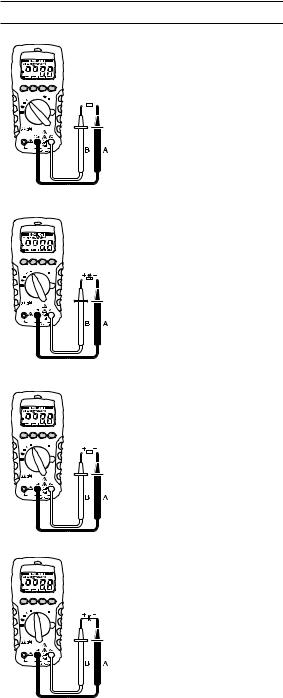
Bild 2: |
Gleichspannungsmessung |
|
|
|
|
|
|
Fig. 2: |
Direct voltage measurement |
|
|
|
|
|
|
Fig. 2: |
Mesure de tension continue |
|
|
|
|
|
|
Fig. 2: |
Medición de tension contínua |
|
|
|
|
|
|
obr. 2: |
Měření stejnosměrného napětí |
|
|
|
|
|
|
figur 2: |
Jævnspændingsmåling |
|
|
|
|
|
|
σχήμα 2: |
Μέτρηση συνεχούς ρεύματος |
|
|
|
|
|
|
||
|
|
|
|
|
|
2. ábra: |
Egyenfeszültség mérés |
|
|
|
|
|
|
ill. 2: |
Misura tensione continua |
|
|
|
|
|
|
Fig. 2: |
Meten van gelijkspanning |
|
|
|
|
|
|
Rys.2: |
Pomiar napięcia stałego |
|
|
|
|
|
|
Imaginea 2: Măsurarea tensiunii continue |
|
|
|
|
|
|
|
рис. 2. |
Измерение напряжения постоянного тока |
|
|
|
|
|
|
Bild 2: |
Likspänningsmätning |
|
|
|
|
|
|
Resim 2: |
Doğru Gerilim Ölçümü |
|
|
|
|
|
|
Bild 3: |
Wechselspannungsmessung |
|
|
|
|
|
|
Fig. 3: |
Alternating voltage measurement |
|
|
|
|
|
|
Fig. 3: |
Mesure de tension alternative |
|
|
|
|
|
|
Fig. 3: |
Medición de tensión alterna |
|
|
|
|
|
|
obr. 3: |
Měření střídavého napětí |
|
|
|
|
|
|
figur 3: |
Vekselspændingsmåling |
|
|
|
|
|
|
σχήμα 3: |
Μέτρηση αναλλασσόμενου ρεύματος |
|
|
|
|
|
|
||
|
|
|
|
|
|
3. ábra: |
Váltakozó feszültség mérés |
|
|
|
|
|
|
ill. 3: |
Misura tensione alternata |
|
|
|
|
|
|
Fig. 3: |
Meten van wisselspanning |
|
|
|
|
|
|
Rys.3: |
Pomiar napięcia przemiennego |
|
|
|
|
|
|
Imaginea 3: Măsurarea tensiunii alternative |
|
|
|
|
|
|
|
рис. 3. |
Измерение напряжения переменного тока |
|
|
|
|
|
|
Bild 3: |
Växelspänningsmätning |
|
|
|
|
|
|
Resim 3: |
Alternatif Gerilim Ölçümü |
|
|
|
|
|
|
BENNING MM 1-2/ 1-3 |
|
|
|
|
|
|
|
Bild 4: |
Gleichstrommessung |
|
|
|
|
|
|
Fig. 4: |
DC current measurement |
|
|
|
|
|
|
Fig. 4: |
Mesure de courant continu |
|
|
|
|
|
|
Fig. 4: |
Medición de corriente contínua |
|
|
|
|
|
|
obr. 4: |
Měření stejnosměrného proudu |
|
|
|
|
|
|
figur 4: |
Jævnstrømsmåling |
|
|
|
|
|
|||
|
|
|
|
|
|||
|
|
|
|
|
|
σχήμα 4: |
Μέτρηση συνεχούς ρεύματος |
|
|
|
|
|
|
4. ábra: |
Egyenáram mérés |
|
|
|
|
|
|
ill. 4: |
Misura corrente continua |
|
|
|
|
|
|
Fig. 4: |
Meten van gelijkstroom |
|
|
|
|
|
|
Rys.4: |
Pomiar prądu stałego |
|
|
|
|
|
|
Imaginea 4: Măsurarea curentului continuu |
|
|
|
|
|
|
|
рис. 4. |
Измерение величины постоянного тока |
|
|
|
|
|
|
Bild 4: |
Likströmsmätning |
|
|
|
|
|
|
Resim 4: |
Doğru Akım Ölçümü |
|
|
|
|
|
|
BENNING MM 1-2/ 1-3 |
|
|
|
|
|
|
|
Bild 5: |
Wechselstrommessung |
|
|
|
|
|
|
Fig. 5: |
AC current measurement |
|
|
|
|
|
|
Fig. 5: |
Mesure de courant alternatif |
|
|
|
|
|
|
Fig. 5: |
Medición de corriente alterna |
|
|
|
|
|
|
obr. 5: |
Měření střídavého proudu |
|
|
|
|
|
|
figur 5: |
Vekselstrømsmåling |
|
|
|
|||||
|
|
|
|
|
|
||
|
|
|
|
|
|
σχήμα 5: |
Μέτρηση εναλλασσόμενου ρεύματος |
|
|
|
|
|
|
5. ábra: |
Váltakozó áram mérés |
|
|
|
|
|
|
ill. 5: |
Misura corrente alternata |
|
|
|
|
|
|
Fig. 5: |
Meten van wisselstroom |
|
|
|
|
|
|
Rys.5: |
Pomiar prądu przemiennego |
|
|
|
|
|
|
Imaginea 5: Măsurarea curentului alternative |
|
|
|
|
|
|
|
рис. 5. |
Измерение величины переменного тока |
|
|
|
|
|
|
Bild 5: |
Växelströmsmätning |
|
|
|
|
|
|
Resim 5: |
Alternatif Akım Ölçümü |
02/ 2011 |
BENNING MM 1 1/ 1 2/ 1 3 |
5 |
D FE HI S
 MM 1-3
AUTO |
HOLD |
|
nmF |
MAX
MIN


RANGE MAX/MIN VoltSensor HOLD

 Hz A
Hz A
V |
°F |
OFF
 Hz
Hz
A
MAX 10A FUSED
 MM 1-3
AUTO |
HOLD |
|
nmF |
MAX
MIN


RANGE MAX/MIN VoltSensor HOLD

 Hz
Hz 
V |
°F |
OFF
 Hz
Hz
A
MAX 10A FUSED
 MM 1-3
AUTO |
HOLD |
|
nmF |
MAX
MIN


RANGE MAX/MIN VoltSensor HOLD

 Hz
Hz 
V |
°F |
OFF
 Hz
Hz
A
MAX 10A FUSED
 MM 1-3
AUTO |
HOLD |
|
nmF |
MAX
MIN


RANGE MAX/MIN VoltSensor HOLD

 Hz
Hz 
OFF
 Hz
Hz
A
MAX 10A FUSED
|
|
|
|
|
|
Bild 6: |
Widerstandsmessung |
|
|
|
|
|
|
Fig. 6: |
Resistance measurement |
|
|
|
|
|
|
Fig. 6: |
Mesure de résistance |
|
|
|
|
|
|
Fig. 6: |
Medición de resistencia |
|
|
|
|
|
|
obr. 6: |
Měření odporu |
|
|
|
|
|
|
figur 6: |
Modstandsmåling |
|
|
|
|
|
|
σχήμα 6: |
Μέτρηση αντίστασης |
|
|
|
|
|
|||
|
|
|
|
|
|
6. ábra |
Ellenállás mérés |
|
|
|
|
|
|
ill. 6: |
Misura di resistenza |
|
|
|
|
|
|
Fig. 6: |
Weerstandsmeting |
|
|
|
|
|
|
Rys.6: |
Pomiar rezystancji |
|
|
|
|
|
|
Imaginea 6: Măsurarea rezistenţei |
|
|
|
|
|
|
|
рис. 6. |
Измерение сопротивления |
|
|
|
|
|
|
Bild 6: |
Resistansmätning |
|
|
|
|
|
|
Resim 6: |
Direnç Ölçümü |
|
|
|
|
|
|
Bild 7: |
Diodenprüfung |
|
|
|
|
|
|
Fig. 7: |
Diode testing |
|
|
|
|
|
|
Fig. 7: |
Contrôle de diodes |
|
|
|
|
|
|
Fig. 7: |
Verificación de diodos |
|
|
|
|
|
|
obr. 7: |
test diod |
|
|
|
|
|
|
figur 7: |
Diodetest |
|
|
|
|
|
|
σχήμα 7: |
Έλεγχος διόδου |
|
|
|
|
||||
|
|
|
|
|
|
||
|
|
|
|
||||
|
|
|
|
|
|
7: ábra: |
Dióda vizsgálat |
|
|
|
|
|
|
ill. 7: |
Prova diodi |
|
|
|
|
|
|
Fig. 7: |
Diod-test |
|
|
|
|
|
|
Rys.7: |
Pomiar diody |
|
|
|
|
|
|
Imaginea 7: Testarea diodelor |
|
|
|
|
|
|
|
рис. 7 |
Проверка диодов |
|
|
|
|
|
|
Bild 7: |
Diodtest |
|
|
|
|
|
|
Resim 7: |
Diyot Kontrolü |
|
|
|
|
|
|
Bild 8: |
Durchgangsprüfung mit Summer |
|
|
|
|
|
|
Fig. 8: |
Continuity testing with buzzer |
|
|
|
|
|
|
Fig. 8: |
Contrôle de continuité avec ronfleur |
|
|
|
|
|
|
Fig. 8: |
Control de continuidad con vibrador |
|
|
|
|
|
|
obr. 8: |
Zkoušku obvodu |
|
|
|
|
|
|
figur 8: |
Gennemgangstest med brummer |
|
|
|
|
|
|
σχήμα 8: |
Έλεγχος συνέχειας με βομβητή |
|
|
|
|
|
|
||
|
|
|
|
|
|
8. ábra: |
Folytonosság vizsgálat zümmögővel |
|
|
|
|
|
|
ill. 8: |
Prova di continuità con cicalino |
|
|
|
|
|
|
Fig. 8: |
Doorgangstest met akoestisch signaal |
|
|
|
|
|
|
Rys.8: |
Sprawdzenie ciągłości obwodu |
|
|
|
|
|
|
Imaginea 8: Testarea continuităţii cu buzzer |
|
|
|
|
|
|
|
рис. 8. |
Проверка целостности цепи |
|
|
|
|
|
|
Bild 8: |
Genomgångskontroll med summer |
|
|
|
|
|
|
Resim 8: |
Sesli uyarıcı ile süreklilik ölçümü |
|
|
|
|
|
|
BENNING MM 1-2/ 1-3 |
|
|
|
|
|
|
|
Bild 9: |
Kapazitätsmessung |
|
|
|
|
|
|
Fig. 9: |
Capacity testing |
|
|
|
|
|
|
Fig. 9: |
Mesure de capacité |
|
|
|
|
|
|
Fig. 9: |
Medición de capacidad |
|
|
|
|
|
|
obr. 9: |
Měření kapacity |
|
|
|
|
|
|
figur 9: |
Kapacitansmåling |
|
|
|
|
|
|
σχήμα 9: |
Μέτρηση χωρητικότητας |
|
|
|
|
|
|
9. ábra: |
Kapacitás mérés |
|
|
|
|
|
|
ill. 9: |
Misura di capacità |
|
|
|
|
|
|
Fig. 9: |
Capaciteitsmeting |
|
|
|
|
|
|
Rys.9: |
Pomiar pojemności |
|
|
|
|
|
|
Imaginea 9: Măsurarea capacităţii |
|
|
|
|
|
|
|
рис. 9 |
Измерение емкости |
|
|
|
|
|
|
Bild 9: |
Kapacitetsmätning |
|
|
|
|
|
|
Resim 9: |
Kapasite Ölçümü |
02/ 2011 |
BENNING MM 1 1/ 1 2/ 1 3 |
6 |

D FE HI S
 MM 1-3
AUTO |
HOLD |
|
nmF |
MAX
MIN
RANGE MAX/MIN VoltSensor HOLD

 Hz A
Hz A
V |
°F |
OFF
 Hz
Hz
A
MAX 10A FUSED
 MM 1-3
AUTO |
HOLD |
|
nmF |
MAX
MIN


RANGE MAX/MIN VoltSensor HOLD

 Hz
Hz 
°F
 Hz
Hz
A
MAX 10A FUSED
BENNING MM 1-2/ 1-3
Bild 10: Frequenzmessung
Fig. 10: Frequency measurement Fig. 10: Mesure de fréquence Fig. 10: Medición de frecuencia obr. 10: Měření frekvence
figur 10: Frekvensmåling σχήμα 10: Μέτρηση συχνότητας 10. ábra: Frekvencia mérés ill. 10: Misura di frequenza Fig. 10: Frequentiemeting
Rys.10: Pomiar częstotliwości Imaginea 10:Măsurarea frecvenţei
рис. 10 Измерение частоты
Bild 10: Frekvensmätning Resim 10: Frekans Ölçümü
BENNING MM 1-3
Bild 11: Temperaturmessung
Fig. 11: Temperature measurement Fig. 11: Mesure de la température Fig. 11: Medición de temperatura obr. 11: Měření teploty
figur 11: Temperaturmåling
σχήμα 11: Μέτρηση θερμοκρασίας 11. ábra: Hőmérséklet mérés ill. 11: Misura di temperatura Fig. 11: Temperatuurmeting Rys.11: Pomiar temperatury Imaginea 11: Măsurarea temperaturii
рис. 11: Измерение температуры
Bild 11: Temperaturmätning
Resim 11: Isı Ölçümü
Bild 12: |
Spannungsindikator mit Summer |
fig. 12: |
Voltage indicator with buzzer |
fig. 12: |
Indicateur de tension avec ronfleur |
fig 12: |
indicador de tensión con vibrador |
obr. 12: |
Indikátor napětí s bzučákem |
figur 12: |
Spændingsindikator med brummer |
εικόνα 12: |
Ένδειξη τάσης με βομβητή |
12. ábra: |
Feszültség indikátor zümmögővel |
ill. 12: |
Indicatore di tensione con cicalino |
fig. 12: |
spanningsindicator met zoemer |
Rys. 12: |
Wskaźnik napięcia z sygnalizacja |
|
dźwiękową |
Imaginea 12:Indicatorul tensiunii cu buzzer |
|
рис. 12: |
Индикатор напряжения с зуммером |
Bild 12: |
Spänningsindikator med summer |
Resim 12: |
Akustik gerilim indikatörü |
Bild 13: |
Batteriewechsel |
Fig. 13: |
Battery replacement |
Fig. 13: |
Remplacement de la pile |
Fig. 13: |
Cambio de pila |
obr. 13: |
Výměna baterií |
figur 13: |
Batteriskift |
σχήμα 13: |
Αντικατάσταση μπαταρίας |
13 ábra: |
Telepcsere |
ill. 13: |
Sostituzione batterie |
Fig. 13: |
Vervanging van de batterijen |
Rys.13: |
Wymiana baterii |
Imaginea 13:Schimbarea bateriilor |
|
рис. 13 |
Замена батареи |
Bild 13: |
Batteribyte |
Resim 13: |
Batarya Değişimi |
02/ 2011 |
BENNING MM 1 1/ 1 2/ 1 3 |
7 |

D FE HI S
BENNING MM 1-2/ 1-3
Bild 14: |
Sicherungswechsel |
Fig. 14: |
Fuse replacement |
Fig. 14: |
Remplacement des fusibles |
Fig. 14: |
Cambio de fusible |
obr. 14: |
Výměna pojistek |
figur 14: |
Sikringsskift |
σχήμα 14: |
αντικατάσταση μπαταρίας |
14 ábra: |
Biztosító csere |
ill. 14: |
Sostituzione fusibile |
Fig. 14: |
Vervanging van de smeltzekeringen |
Rys.14: |
Wymiana bezpiecznika |
Imaginea 14:Schimbarea siguranţei |
|
рис. 14 |
Замена предохранителей |
Bild 14: |
Byte av säkring |
Resim 14: |
Sigorta Değişimi |
Bild 15: |
Aufwicklung der Sicherheitsmessleitung |
Fig. 15: |
Winding up the safety measuring leads |
Fig. 15: |
Enroulement du câble de mesure de |
|
sécurité |
Fig. 15: |
Arrollamiento de la conducción protegida |
|
de medición |
obr. 15: |
navíjení měřících kabelů |
figur 15: |
Opvikling af sikkerhedsmåleledning |
σχήμα 15: |
Τυλίξτε τα καλώδια μέτρησης |
15 ábra: |
A mérővezetékek felcsavarása |
ill. 15: |
Avvolgimento dei cavetti di sicurezza |
Fig. 15: |
Wikkeling van veiligheidsmeetsnoeren |
Rys.15: |
Zwijanie przewodów pomiarowych |
Imaginea 15:Înfăşurarea cablului de măsurat de |
|
|
siguranţă |
рис. 15 |
Намотка измерительных проводов |
Bild 15: |
Fastlindning av säkerhetsmätkablarna |
Resim 15: |
Emniyet Ölçüm tesisatının sarılması |
BENNING MM 1-1/ 1-2/ 1-3
Bild 16: |
Aufstellung |
Fig. 16: |
Erecting |
Fig. 16: |
Installation |
Fig. 16: |
Colocación |
obr. 16: |
postavení |
figur 16: |
Opstilling |
σχήμα 16: |
Κρατώντας όρθιο |
16 ábra: |
felállítása |
ill. 16: |
Posizionamento |
Fig. 16: |
Opstelling |
Rys.16: |
w pozycji stojącej |
Imaginea 16:Aşezarea |
|
рис. 16 |
Установка |
Bild 16: |
Uppställning |
Resim 16: |
kurulumu |
02/ 2011 |
BENNING MM 1 1/ 1 2/ 1 3 |
8 |

D
Bedienungsanleitung
BENNING MM 1 1/ 1 2/ 1 3
Digital-Multimeter zur
-Gleichspannungsmessung
-Wechselspannungsmessung
-Gleichstrommessung (BENNING MM 1-2/ 1-3)
-Wechselstrommessung (BENNING MM 1-2/ 1-3)
-Widerstandsmessung
-Diodenprüfung
-Durchgangsprüfung
-Kapazitätsmessung (BENNING MM 1-2/ 1-3)
-Frequenzmessung (BENNING MM 1-2/ 1-3)
-Temperaturmessung (BENNING MM 1-3)
Inhaltsverzeichnis
1.Benutzerhinweise
2.Sicherheitshinweise
3.Lieferumfang
4.Gerätebeschreibung
5.Allgemeine Angaben
6.Umgebungsbedingungen
7.Elektrische Angaben
8.Messen mit dem BENNING MM 11/ 1 2/ 1 3
9.Instandhaltung
10.Anwendung des Klappständers und der Aufhängevorrichtung
11.Technische Daten des Messzubehörs
12.Umweltschutz
1.Benutzerhinweise
Diese Bedienungsanleitung richtet sich an
-Elektrofachkräfte und
-elektrotechnisch unterwiesene Personen.
Das BENNING MM 1-1/ 1-2/ 1-3 ist zur Messung in trockener Umgebung vorgesehen. Es darf nicht in Stromkreisen mit einer höheren Nennspannung als 1000 V DC und 750 V AC eingesetzt werden (Näheres hierzu im Abschnitt 6. „Umgebungsbedingungen“).
In der Bedienungsanleitung und auf dem BENNING MM 1 1/ 1 2/ 1 3 werden folgende Symbole verwendet:
Warnung vor elektrischer Gefahr!
Steht vor Hinweisen, die beachtet werden müssen, um Gefahren für Menschen zu vermeiden.
Achtung Dokumentation beachten!
Das Symbol gibt an, dass die Hinweise in der Bedienungsanleitung zu beachten sind, um Gefahren zu vermeiden.
Dieses Symbol auf dem BENNING MM 1-1/ 1-2/ 1-3 bedeutet, dass
das BENNING MM 1-1/ 1-2/ 1-3 schutzisoliert (Schutzklasse II) ausgeführt ist.
Dieses Symbol auf dem BENNING MM 1-2/ 1-3 weist auf die eingebauten Sicherungen hin.
Dieses Symbol erscheint in der Anzeige für eine entladene Batterie. Dieses Symbol kennzeichnet den Bereich „Diodenprüfung“.
Dieses Symbol kennzeichnet den Bereich „Durchgangsprüfung“. Der Summer dient der akustischen Ergebnisausgabe.
Dieses Symbol kennzeichnet den Bereich „Kapazitätsprüfung“. (DC) GleichSpannung oder Strom.
(AC) WechselSpannung oder Strom.
Erde (Spannung gegen Erde).
02/ 2011 |
BENNING MM 1 1/ 1 2/ 1 3 |
1 |

D
2. Sicherheitshinweise
Das Gerät ist gemäß
DIN VDE 0411 Teil 1/ EN 61010-1
geprüft und zugelassen und hat das Werk in einem sicherheitstechnisch einwandfreien Zustand verlassen.
Um diesen Zustand zu erhalten und einen gefahrlosen Betrieb sicherzustellen, muss der Anwender die Hinweise und Warnvermerke beachten, die in dieser Anleitung enthalten sind.
DasGerätdarfnurinStromkreisenderÜberspannungskategorieII mit max. 1000 V Leiter gegen Erde oder Überspannungskategorie
III mit 600 V Leiter gegen Erde benutzt werden.
Hierzu sind geeignete Messleitungen zu verwenden. Bei Mes sungen innerhalb der Messkategorie III darf das hervorstehende leitfähige Teil einer Kontaktspitze der Messleitung nicht länger als
4 mm sein.
Vor Messungen innerhalb der Messkategorie III müssen, die dem
Set beigestellten, mit CAT III und CAT IV gekennzeichneten, Auf steckkappen auf die Kontaktspitzen aufgesteckt werden. Diese
Maßnahme dient dem Benutzerschutz.
Beachten Sie, dass Arbeiten an spannungsführenden Teilen und Anlagen grundsätzlich gefährlich sind. Bereits Spannungen ab 30 V AC und 60 V DC können für den Menschen lebensgefährlich sein.
Vor jeder Inbetriebnahme überprüfen Sie das Gerät und die Leitungen auf Beschädigungen.
Ist anzunehmen, dass ein gefahrloser Betrieb nicht mehr möglich ist, ist das Gerät außer Betrieb zu setzen und gegen unbeabsichtigten Betrieb zu sichern.
Es ist anzunehmen, dass ein gefahrloser Betrieb nicht mehr möglich ist,
-wenn das Gerät oder die Messleitungen sichtbare Beschädigungen aufweisen,
-wenn das Gerät nicht mehr arbeitet,
-nach längerer Lagerung unter ungünstigen Verhältnissen,
-nach schweren Transportbeanspruchungen.
Um eine Gefährdung auszuschließen
-berühren Sie die Messleitungen nicht an den blanken
Messspitzen,
-stecken Sie die Messleitungen in die entsprechend gekennzeichneten Messbuchsen am Multimeter
3.Lieferumfang
Zum Lieferumfang des BENNING MM 1-1/ 1-2/ 1-3 gehören:
3.1ein Stück BENNING MM 1-1/ 1-2/ 1-3,
3.2ein Stück Sicherheitsmessleitung, rot (L = 1,4 m),
3.3ein Stück Sicherheitsmessleitung, schwarz (L = 1,4 m),
3.4ein Stück Messadapter mit Drahttemperatursensor Typ K (BENNING MM 1-3)
3.5ein Stück Gummi-Aufhängevorrichtung,
3.6ein Stück Kompakt-Schutztasche,
3.7zwei 1,5-V-Micro-Batterien sind zur Erstbestückung im Gerät eingebaut,
3.8eine Sicherung zur Erstbestückung ist im Gerät eingebaut (BENNING MM 1-2/ 1-3),
3.9eine Bedienungsanleitung.
Hinweis auf optionales Zubehör (BENNING MM 1-3):
-Temperaturfühler (K-Typ) aus V4A-Rohr
Anwendung: Einstichfühler für weichplastische Medien, Flüssigkeiten, Gas und Luft
Messbereich: - 196 °C bis + 800 °C
Abmessungen: Länge = 210 mm, Rohrlänge = 120 mm, Rohrdurch messer = 3 mm, V4A (T.Nr. 044121)
Hinweis auf Verschleißteile:
-Das BENNING MM 1-1/ 1-2/ 1-3 wird durch zwei eingebaute 1,5-V-Micro- Batterien (IEC 6 LR 03) gespeist.
-Das BENNING MM 1-2/ 1-3 enthält eine Sicherung zum Überlastschutz: Ein Stück Sicherung Nennstrom 10 A flink (600 V), 50 kA (T.Nr. 748263)
-Die oben genannten Sicherheitsmessleitungen (geprüftes Zubehör) entsprechen CAT III 1000 V und sind für einen Strom von 10 A zugelassen.
02/ 2011 |
BENNING MM 1 1/ 1 2/ 1 3 |
2 |
D
4.Gerätebeschreibung
siehe Bild 1a, 1b, 1c:Gerätefrontseite
Die in den Bildern 1a, 1b und 1c angegebenen Anzeigeund Bedienelemente werden wie folgt bezeichnet:
Digitalanzeige, für den Messwert und die Anzeige der Bereichsüberschreitung,
Polaritätsanzeige,
Batterieanzeige, erscheint bei entladener Batterie,
MAX/ MIN-Taste, Speicherung des höchsten und niedrigsten Messwertes (BENNING MM 1-2/ 1-3)
5 VoltSensor-Taste, zur Ermittlung von AC-Spannung gegen Erde,
RANGE-Taste, Umschaltung automatischer/ manueller Messbereich,HOLD-Taste, Speicherung des angezeigten Messwertes,
8 |
Drehschalter, für Wahl der Messfunktion, |
|
9 |
Buchse (positive1), für V, Ω, |
, Hz, |
JCOM-Buchse, gemeinsame Buchse für Strom-, Spannungs-, Widerstands-, Frequenz-, Temperatur-, Kapazitätsmessungen, Durchgangsund Diodenprüfung,
K Buchse (positive1), für A-Bereich, für Ströme bis 10 A (BENNING MM 1 2/ 1 3),
L Aufhängevorrichtung
MLED, für Spannungsindikator
1) Hierauf bezieht sich die automatische Polaritätsanzeige für Gleichstrom und -spannung
5.Allgemeine Angaben
5.1 Allgemeine Angaben zum Multimeter
5.1.1Die Digitalanzeige ist als 3½-stellige Flüssigkristallanzeige mit 16 mm Schrifthöhe mit Dezimalpunkt ausgeführt. Der größte Anzeigewert ist 2000.
5.1.2Die Polaritätsanzeige wirkt automatisch. Es wird nur eine Polung entgegen der Buchsendefinition mit „-“ angezeigt.
5.1.3Die Bereichsüberschreitung wird mit „OL” oder „-OL” und teilweise mit einer akustischen Warnung angezeigt.
Achtung, keine Anzeige und Warnung bei Überlast!
5.1.4Die „MAX/ MIN“-Tastenfunktion erfasst und speichert automatisch den höchsten und niedrigsten Messwert, Messbereich ggf. durch „RANGE“-Taste vorwählen. Durch Tastenbetätigung werden folgende Werte angezeigt:
„MAX“ zeigt den gespeicherten höchsten und „MIN“ den niedrigsten Wert an. Die fortlaufende Erfassung des MAX-/ MINWertes kann durch Betätigung der Taste „HOLD“ gestoppt, bzw gestartet werden. Durch längeren Tastendruck (1 Sekunde) auf die Taste „MAX/ MIN“ wird in den Normalmodus zurückgeschaltet.
5.1.5Die Bereichstaste „RANGE“ dient zur Weiterschaltung der manuellen Messbereiche bei gleichzeitiger Ausblendung von „AUTO“ im Display. Durch längeren Tastendruck (1 Sekunde) wird die automatische Bereichswahl gewählt (Anzeige „AUTO“).
5.1.6Messwertspeicherung „HOLD“: Durch Betätigen der Taste „HOLD“ lässt sich das Messergebnis speichern. Im Display wird gleichzeitig das Symbol „HOLD“ eingeblendet. Erneutes Betätigen der Taste schaltet in den Messmodus zurück.
5.1.7Die Messrate des BENNING MM 1-1/ 1-2/ 1-3 beträgt nominal 2 Messungen pro Sekunde für die Digitalanzeige.
5.1.8Das BENNING MM 1-1/ 1-2/ 1-3 wird durch den Drehschalter 8 einoder ausgeschaltet. Ausschaltstellung „OFF“.
5.1.9Das BENNING MM 1-1/ 1-2/ 1-3 schaltet sich nach ca. 10 min selbsttätig ab (APO, Auto-Power-Off). Es schaltet sich wieder ein, wenn eine Taste oder der Drehschalter betätigt wird. Ein Summerton signalisiert die selbsttätige Abschaltung des Gerätes. Die automatische Abschaltung lässt sich deaktivieren indem sie die Taste „RANGE“ betätigen und gleichzeitig das BENNING MM 1-1/ 1-2/ 1-3 aus der Schaltstellung „OFF“ einschalten.
5.1.10Temperaturkoeffizient des Messwertes: 0,15 x (angegebene Mess genauigkeit)/ °C < 18 °C oder > 28 °C, bezogen auf den Wert bei der Referenztemperatur von 23 °C.
5.1.11Das BENNING MM 1-1/ 1-2/ 1-3 wird durch zwei 1,5-V-Micro-Batterien gespeist (IEC 6 LR 03).
5.1.12Wenn die Batteriespannung unter die vorgesehene Arbeitsspannung des BENNING MM 1-1/ 1-2/ 1-3 sinkt, erscheint in der Anzeige ein Batteriesymbol .
5.1.13Die Lebensdauer der Batterien beträgt etwa 250 Stunden (Alkalibatterie).
5.1.14Geräteabmessungen: (L x B x H) = 156 x 74 x 44 mm mit Aufhängevorrichtung Gerätegewicht: 320 g mit Aufhängevorrichtung und Batterie
5.1.15Die mitgelieferten Sicherheitsmessleitungen sind ausdrücklich für die Nennspannung und dem Nennstrom des BENNING MM 1-1/ 1-2/ 1-3
02/ 2011 |
BENNING MM 1 1/ 1 2/ 1 3 |
3 |

D
geeignet.
5.1.16Das BENNING MM 1-1/ 1-2/ 1-3 kann durch eine ausklappbare Stütze aufgestellt oder durch die Aufhängevorrichtung befestigt werden.
5.1.17Das BENNING MM 1-1/ 1-2/ 1-3 besitzt kopfseitig einen Aufnahmesensor als Spannungsindikator zur Lokalisierung von geerdeten Wechselspannungen.
6.Umgebungsbedingungen
-Das BENNING MM 1-1/ 1-2/ 1-3 ist für Messungen in trockener Umgebung vorgesehen,
-Barometrische Höhe bei Messungen: Maximal 2000 m,
-Überspannungskategorie/ Aufstellungskategorie: IEC 60664-1/ IEC 61010-1
→ 600 V Kategorie III; 1000 V Kategorie II,
-Verschmutzungsgrad: 2,
-Schutzart: IP 30 DIN VDE 0470-1 IEC/EN 60529
IP 30 bedeutet: Schutz gegen Zugang zu gefährlichen Teilen und Schutz gegen feste Fremdkörper > 2,5 mm Durchmesser, (3 - erste Kennziffer). Kein Wasserschutz, (0 - zweite Kennziffer).
-Arbeitstemperatur und relative Luftfeuchte:
Bei Arbeitstemperatur von 0 °C bis 30 °C: relative Luftfeuchte kleiner 80 %, Bei Arbeitstemperatur von 31 °C bis 40 °C: relative Luftfeuchte kleiner 75 %, Bei Arbeitstemperatur von 41 °C bis 50 °C: relative Luftfeuchte kleiner 45 %,
-Lagerungstemperatur: Das BENNING MM 1-1/ 1-2/ 1-3 kann bei Temperaturen von - 15 °C bis + 60 °C (Luftfeuchte 0 bis 80 %) gelagert werden. Dabei ist die Batterie aus dem Gerät herauszunehmen.
7.Elektrische Angaben
Bemerkung: Die Messgenauigkeit wird angegeben als Summe aus
-einem relativen Anteil des Messwertes und
-einer Anzahl von Digit (d.h. Zahlenschritte der letzten Stelle).
Diese Messgenauigkeit gilt bei Temperaturen von 18 °C bis 28 °C und einer relativen Luftfeuchtigkeit kleiner 80 %.
7.1 Gleichspannungsbereiche
Der Eingangswiderstand beträgt 10 MΩ.
|
|
|
|
|
|
Messbereich *3 |
Auflösung |
Messgenauigkeit |
|
Überlastschutz |
|
|
|
± (0,5 % des Messwertes + |
2 Digit) |
1000 VDC |
|
200 mV |
100 µV |
||||
|
|
||||
2 V |
1 mV |
± (0,5 % des Messwertes + |
2 Digit) |
1000 VDC |
|
|
|
||||
|
|
± (0,5 % des Messwertes + |
2 Digit) |
1000 VDC |
|
20 V |
10 mV |
||||
|
|
||||
200 V |
100 mV |
± (0,5 % des Messwertes + |
2 Digit) |
1000 VDC |
|
|
|
||||
1000 V |
1 V |
± (0,5 % des Messwertes + |
2 Digit) |
1000 VDC |
|
|
|
||||
7.2 Wechselspannungsbereiche |
|
|
|||
Der Eingangswiderstand beträgt 10 MΩ parallel 100 pF. |
|
||||
|
|
|
|
|
|
|
|
Messgenauigkeit *1 |
|
|
|
Messbereich *3 |
Auflösung |
|
Überlastschutz |
||
im Frequenzbereich 50 Hz - 300 Hz |
|||||
|
|
|
|||
|
|
± (2,0 % des Messwertes + 5 Digit) *2 |
750 V |
||
200 mV |
100 µV |
||||
|
|
|
Digit) *2 |
eff |
|
2 V |
1 mV |
± (1,5 % des Messwertes + 5 |
750 V |
||
|
|
im Frequenzbereich 50 Hz - 500 Hz |
eff |
||
|
|
|
|||
|
|
± (1,5 % des Messwertes + 5 Digit) *2 |
750 V |
||
20 V |
10 mV |
||||
|
|
± (1,5 % des Messwertes + 5 Digit) *2 |
eff |
||
200 V |
100 mV |
750 V |
|||
|
|
± (1,5 % des Messwertes + 5 Digit) *2 |
eff |
||
|
|
750 V |
|||
750 V |
1 V |
||||
|
|
|
|
eff |
|
Der Messwert des BENNING MM 1-1/ 1-2/ 1-3 wird durch Mittelwertgleich richtung gewonnen und als Effektivwert angezeigt.
*1 |
Die Messgenauigkeit ist spezifiziert für eine Sinuskurvenform. Bei nicht |
|
sinusförmigen Kurvenformen wird der Anzeigewert ungenauer. So ergibt |
|
sich für folgende Crest-Faktoren ein zusätzlicher Fehler: |
|
Crest-Factor von 1,4 bis 3,0 zusätzlicher Fehler ± 1,5 % |
*2 |
Crest-Factor von 3,0 bis 4,0 zusätzlicher Fehler ± 3 % |
Gültig für Sinuskurvenform 50 Hz/ 60 Hz |
|
*3 |
Bei der automatischen Bereichswahl (AUTO) kann der Umschaltpunkt |
|
bereits bei einem Wert von 1400 liegen! |
02/ 2011 |
BENNING MM 1 1/ 1 2/ 1 3 |
4 |

D
7.3 Gleichstrombereiche (BENNING MM 1-2/ 1-3) Überlastungsschutz:
-10 A (600 V)-Sicherung, flink, 50 kA am 10 A - Eingang (BENNING MM 1-2/ 1-3),
|
|
|
Spannungsabfall |
Messbereich |
Auflösung |
Messgenauigkeit |
|
2 A |
1 mA |
± (1,0 % des Messwertes + 3 Digit) |
2 V max. |
10 A *5 |
10 mA |
± (1,0 % des Messwertes + 3 Digit) |
2 V max. |
7.4 Wechselstrombereiche (BENNING MM 1-2/ 1-3) Überlastungsschutz:
-10 A (600 V)-Sicherung, flink, 50 kA am 10 A - Eingang (BENNING MM 1-2/ 1-3),
|
|
Messgenauigkeit *4 |
|
|
Messbereich |
Auflösung |
Spannungsabfall |
||
im Frequenzbereich 50 Hz - 500 Hz |
||||
|
|
|
||
|
1 mA |
± (1,5 % des Messwertes + 5 Digit) |
2 V max. |
|
2 A |
||||
10 A *5 |
10 mA |
± (1,5 % des Messwertes + 5 Digit) |
2 V max. |
Der Messwert wird durch Mittelwertgleichrichtung gewonnen und als Effektivwert
angezeigt. |
|
*4 |
Die Messgenauigkeit ist spezifiziert für eine Sinuskurvenform. Bei nicht |
|
sinusförmigen Kurvenformen wird der Anzeigewert ungenauer. So ergibt |
|
sich für folgende Crest-Faktoren ein zusätzlicher Fehler: |
|
Crest-Factor von 1,4 bis 3,0 zusätzlicher Fehler ± 1,5 % |
*5 |
Crest-Factor von 3,0 bis 4,0 zusätzlicher Fehler ± 3 |
Ab Stromwerten ≥ 7 A ist die maximal erlaubte Einschaltzeit limitiert. |
|
Messwert |
Maximale Messzeit |
Mindest Pausenzeit |
10 A |
4 min. |
10 min. |
9 A |
5 min. |
10 min. |
8 A |
7 min. |
10 min. |
7 A |
10 min. |
10 min. |
7.5 Widerstandsbereiche
Überlastschutz bei Widerstandsmessungen: 600 Veff
|
|
|
|
Max. Leerlauf- |
Messbereich |
*6 Auflösung |
|
Messgenauigkeit |
|
|
spannung |
|||
|
|
|
|
|
|
|
|
± (0,7 % des Messwertes + 3 Digit) |
1,3 V |
200 Ω |
0,1 Ω |
|||
|
|
|
± (0,7 % des Messwertes + 3 Digit) |
1,3 V |
2 kΩ |
1 Ω |
|||
|
|
|
± (0,7 % des Messwertes + 3 Digit) |
1,3 V |
20 kΩ |
10 Ω |
|||
|
|
|
± (0,7 % des Messwertes + 3 Digit) |
1,3 V |
200 kΩ |
100 Ω |
|||
|
|
|
± (1,0 % des Messwertes + 3 Digit) |
1,3 V |
2 MΩ |
1 kΩ |
|||
|
|
|
± (1,5 % des Messwertes + 3 Digit) |
1,3 V |
20 MΩ |
10 kΩ |
|||
*6 Bei der |
automatischen |
Bereichswahl (AUTO) kann der |
Umschaltpunkt |
|
bereits bei einem Wert von 1400 liegen!
7.6 Diodenund Durchgangsprüfung
Die angegebene Messgenauigkeit gilt im Bereich zwischen 0,4 V und 0,8 V. Überlastschutz bei Diodenprüfungen: 600 Veff
Der eingebaute Summer ertönt bei einem Widerstand R kleiner 25 Ω.
|
|
|
Max. |
Max. Leerlauf- |
|
Mess- |
|
|
|||
Auflösung |
Messgenauigkeit |
||||
bereich |
Messstrom |
spannung |
|||
|
|
||||
|
10 mV |
± (1,5 % des Messwertes + 5 Digit) |
1,5 mA |
2,0 V |
7.7 Kapazitätsbereiche (BENNING MM 1-2/ 1-3)
Bedingungen: Kondensatoren entladen und entsprechend der angegebenen Polarität anlegen.
Überlastschutz bei Kapazitätsmessungen: 600 Veff |
|
||
|
|
Messgenauigkeit |
|
Messbereich |
Auflösung |
|
|
2 nF |
1 pF |
± (1,9 % des Messwertes + 8 Digit) |
|
20 nF |
10 pF |
± (1,9 % des Messwertes + 8 Digit) |
|
200 nF |
100 pF |
± (1,9 % des Messwertes + 8 Digit) |
|
2 µF |
1 nF |
± (1,9 % des Messwertes + 8 Digit) |
|
|
|
|
|
02/ 2011 |
BENNING MM 1 1/ 1 2/ 1 3 |
5 |
|

D
20 µF |
10 nF |
± (1,9 % des Messwertes + 8 Digit) |
200 µF |
100 nF |
± (1,9 % des Messwertes + 8 Digit) |
2 mF |
1 µF |
± (1,9 % des Messwertes + 8 Digit) |
< 10 Digit bei schwankender Anzeige
7.8 Frequenzbereiche (BENNING MM 1-2/ 1-3) Überlastschutz bei Frequenzmessungen: 600 Veff
Minimale Impulsbreite > 25 ns; Arbeitszyklusbegrenzung > 30 % und < 70 %
Mess- |
Auf- |
Messgenauigkeit für 5 Veff max. |
Empfindlichkeit |
|
bereich |
lösung |
|||
|
|
|||
2 kHz |
1 Hz |
± (0,01 % des Messwertes + 1 Digit) |
> 1,5 < 5 Veff |
|
20 kHz |
10 Hz |
± (0,01 % des Messwertes + 1 Digit) |
> 1,5 < 5 Veff |
|
200 kHz |
100 Hz |
± (0,01 % des Messwertes + 1 Digit) |
> 1,5 < 5 Veff |
|
2 MHz |
1 kHz |
± (0,01 % des Messwertes + 1 Digit) |
> 2 < 5 Veff |
|
20 MHz |
10 kHz |
± (0,01 % des Messwertes + 1 Digit) |
> 2 < 5 Veff |
7.9 Temperaturbereiche °C (BENNING MM 1-3)
Eine Temperaturmessung (BENNING MM 1-3) ist nur mit dem beiliegenden Temperaturmessadapter möglich.
Überlastschutz bei Temperaturmessung: 600 Veff
Messbereich |
Auflösung |
Messgenauigkeit |
-20 °C ~ 0 °C |
1 °C |
± (2 % + 4 °C) |
1 °C ~ 100 °C |
1 °C |
± (1 % + 3 °C) |
101 °C ~ 500 °C |
1 °C |
± (2 % + 3 °C) |
501 °C ~ 800 °C |
1 °C |
± (3 % + 2 °C) |
7.10 Temperaturbereiche °F (BENNING MM 1-3)
Eine Temperaturmessung (BENNING MM 1-3) ist nur mit dem beiliegenden Temperaturmessadapter möglich.
Überlastschutz bei Temperaturmessung: 600 Veff
Messbereich |
Auflösung |
Messgenauigkeit |
-4 °F ~ 32 °F |
1 °F |
± (2 % + 8 °F) |
33 °F ~ 212 °F |
1 °F |
± (1 % + 6 °F) |
213 °F ~ 932 °F |
1 °F |
± (2 % + 6 °F) |
933 °F ~ 1472 °F |
1 °F |
± (3 % + 4 °F) |
8. Messen mit dem BENNING MM 1-1/ 1-2/ 1-3 8.1 Vorbereiten der Messung
Benutzen und lagern Sie das BENNING MM 1-1/ 1-2/ 1-3 nur bei den angegebenen Lagerund Arbeitstemperaturbedingungen, vermeiden Sie dauernde Sonneneinstrahlung.
-Angaben von Nennspannung und Nennstrom auf den Sicherheitsmessleitungen überprüfen. Die zum Lieferumfang gehörenden Sicherheitsmessleitungen entsprechen in Nennspannung und Nennstrom dem BENNING MM 1-1/ 1-2/ 1-3.
-Isolation der Sicherheitsmessleitungen überprüfen. Wenn die Isolation beschädigt ist, sind die Sicherheitsmessleitungen sofort auszusondern.
-Sicherheitsmessleitungen auf Durchgang prüfen. Wenn der Leiter in der Sicherheitsmessleitung unterbrochen ist, sind die Sicherheitsmessleitungen sofort auszusondern.
-Bevor am Drehschalter 8 eine andere Funktion gewählt wird, müssen die Sicherheitsmessleitungen von der Messstelle getrennt werden.
-Starke Störquellen in der Nähe des BENNING MM 1-1/ 1-2/ 1-3 können zu instabiler Anzeige und zu Messfehlern führen.
8.2Spannungsund Strommessung
Maximale Spannung gegen Erdpotential beachten!
Elektrische Gefahr!
Die höchste Spannung, die an den Buchsen,
-COM-Buchse J
- Buchse für V, Ω, |
, Hz 9 |
-Buchse für 10 A-Bereich K (BENNING MM 1-2/ 1-3)
02/ 2011 |
BENNING MM 1 1/ 1 2/ 1 3 |
6 |

D
des BENNING MM 1-1/ 1-2/ 1-3 gegenüber Erde liegen darf, beträgt 1000 V.
Elektrische Gefahr!
Maximale Schaltkreisspannung bei Strommessung 500 V! Bei
Sicherungsauslösung über 500 V ist eine Beschädigung des Gerätes möglich. Von einem beschädigten Gerät kann eine elektrische Gefährdung ausgehen!
8.2.1Spannungsmessung
-Mit dem Drehschalter 8 die gewünschte Funktion (V AC) oder (V DC) am BENNING MM 1-1/ 1-2/ 1-3 wählen.
-Die schwarze Sicherheitsmessleitung mit der COM-Buchse J am BENNING MM 1-1/ 1-2/ 1-3 kontaktieren.
-Die rote Sicherheitsmessleitung mit der Buchse für V, ,  , Hz 9 am BENNING MM 1-1/ 1-2/ 1-3 kontaktieren.
-Die Sicherheitsmessleitungen mit den Messpunkten kontaktieren, Messwert an der Digitalanzeige am BENNING MM 1-1/ 1-2/ 1-3 ablesen.
siehe Bild 2: Gleichspannungsmessung siehe Bild 3: Wechselspannungsmessung
8.2.2Strommessung (BENNING MM 1-2/ 1-3)
-Mit dem Drehschalter 8 den gewünschten Bereich und Funktion (A AC) oder (A DC) am BENNING MM 1-2/ 1-3 wählen.
-Die schwarze Sicherheitsmessleitung mit der COM-Buchse J am BENNING MM 1-2/ 1-3 kontaktieren.
-Die rote Sicherheitsmessleitung mit der Buchse für den 10 A-Bereich K (Gleichoder Wechselströme bis 10 A) am BENNING MM 1-2/ 1-3 kontaktieren.
-Die Sicherheitsmessleitungen mit den Messpunkten kontaktieren, Messwert an der Digitalanzeige am BENNING MM 1-2/ 1-3 ablesen.
siehe Bild 4: Gleichstrommessung (BENNING MM 1-2/ 1-3) siehe Bild 5: Wechselstrommessung (BENNING MM 1-2/ 1-3)
8.3 Widerstandsmessung
- Mit dem Drehschalter 8 die gewünschte Funktion (Ω) am
BENNING MM 1-1/ 1-2/ 1-3 wählen.
-Die schwarze Sicherheitsmessleitung mit der COM-Buchse J am BENNING MM 1-1/ 1-2/ 1-3 kontaktieren.
-Die rote Sicherheitsmessleitung mit der Buchse für V, Ω,  , Hz 9 am BENNING MM 1-1/ 1-2/ 1-3 kontaktieren.
-Die Sicherheitsmessleitungen mit den Messpunkten kontaktieren, den Messwert an der Digitalanzeige am BENNING MM 1-1/ 1-2/ 1-3 ablesen.
siehe Bild 6: Widerstandsmessung
8.4 Diodenprüfung
-Mit dem Drehschalter 8 die gewünschte Funktion ( ) am BENNING MM 1-1/ 1-2/ 1-3 wählen.
-Die schwarze Sicherheitsmessleitung mit der COM-Buchse J am BENNING MM 1-1/ 1-2/ 1-3 kontaktieren.
-Die rote Sicherheitsmessleitung mit der Buchse für V, Ω,  , Hz 9 am BENNING MM 1-1/ 1-2/ 1-3 kontaktieren.
-Die Sicherheitsmessleitungen mit den Diodenanschlüssen kontaktieren, den Messwert an der Digitalanzeige am BENNING MM 1-1/ 1-2/ 1-3 ablesen.
-Für eine normale in Flussrichtung angelegte Si-Diode wird die Flussspan nung zwischen 0,400 V bis 0,900 V angezeigt. Die Anzeige „000“ deutet auf einen Kurzschluss in der Diode hin, die Anzeige „OL“ deutet auf eine Unterbrechung in der Diode hin.
-Für eine in Sperrrichtung angelegte Diode wird „OL“ angezeigt. Ist die
Diode fehlerhaft, werden „000“ oder andere Werte angezeigt. siehe Bild 7: Diodenprüfung
8.5 Durchgangsprüfung mit Summer
-Mit dem Drehschalter 8 die gewünschte Funktion ( ) am BENNING MM 1-1/ 1-2/ 1-3 wählen.
-Die schwarze Sicherheitsmessleitung mit der COM-Buchse J am BENNING MM 1-1/ 1-2/ 1-3 kontaktieren.
-Die rote Sicherheitsmessleitung mit der Buchse für V, Ω,  , Hz 9 am BENNING MM 1-1/ 1-2/ 1-3 kontaktieren.
-Die Sicherheitsmessleitungen mit den Messpunkten kontaktieren. Unter schreitet der Leitungswiderstand zwischen der COM-Buchse J und der
Buchse für V, Ω,  , Hz 9 25 Ω, ertönt im BENNING MM 1-1/ 1-2/ 1-3 der eingebaute Summer.
siehe Bild 8: Durchgangsprüfung mit Summer
02/ 2011 |
BENNING MM 1 1/ 1 2/ 1 3 |
7 |

D
8.6 Kapazitätsmessung (BENNING MM 1-2/ 1-3)
Kondensatoren vor Kapazitätsmessungen vollständig entladen!
Niemals Spannung an die Buchsen für Kapazitätsmessung
anlegen! Das Gerät kann beschädigt oder zerstört werden! Von einem beschädigten Gerät kann eine elektrische Gefährdung ausgehen!
-Mit dem Drehschalter 8 die gewünschte Funktion ( ) am BENNING MM 1-2/ 1-3 wählen.
-Polarität des Kondensators ermitteln und Kondensator vollständig entladen.
-Die schwarze Sicherheitsmessleitung mit der COM-Buchse J am BENNING MM 1-2/ 1-3 kontaktieren.
-Die rote Sicherheitsmessleitung mit der Buchse für V, Ω,  , Hz 9 am BENNING MM 1-2/ 1-3 kontaktieren.
-Die Sicherheitsmessleitungen mit dem entladenen Kondensator entsprechend seiner Polarität kontaktieren, Messwert an der Digitalanzeige am BENNING MM 1-2/ 1-3 ablesen.
siehe Bild 9: |
Kapazitätsmessung |
8.7 Frequenzmessung (BENNING MM 1-2/ 1-3)
-Mit dem Drehschalter 8 die gewünschte Funktion (Hz) am BENNING MM 1-2/ 1-3 wählen.
-Die schwarze Sicherheitsmessleitung mit der COM-Buchse J am BENNING MM 1-2/ 1-3 kontaktieren.
-Die rote Sicherheitsmessleitung mit der Buchse für V, Ω,  , Hz 9 am BENNING MM 1-2/ 1-3 kontaktieren. Beachten Sie die minimale Empfindlichkeit für Frequenzmessungen am BENNING MM 1-2/ 1-3!
-Die Sicherheitsmessleitungen mit den Messpunkten kontaktieren, den Messwert an der Digitalanzeige am BENNING MM 1-2/ 1-3 ablesen.
siehe Bild 10: |
Frequenzmessung |
8.8 Temperaturmessung (BENNING MM 1-3)
-Mit dem Drehschalter 8 die gewünschte Funktion (°C oder °F) am BENNING MM 1-3 wählen.
-Den Temperaturadapter mit der Temperaturmessleitung mit der COMBuchse (-) J und der Buchse für V, Ω, , Hz (+) 9 polrichtig kontaktieren.
-Das Ende der Temperaturmessleitung im Bereich der zu überwachenden Wärmequelle anordnen. Messwert an der Digitalanzeige 1 am BENNING MM 1-3 ablesen.
siehe Bild 11: |
Temperaturmessung |
8.9 Spannungsindikator
Die Spannungsindikatorfunktion ist aus jeder Stellung des Drehschalters möglich. Als Spannungsindikator werden keine Messleitungen benötigt (berührungslose Erfassung eines Wechselfeldes). Im Kopfbereich hinter der
LED befindet sich der Aufnahmesensor. Bei Betätigung der "VoltSensor"-Taste
5 erlischt das Anzeigedisplay (falls eingeschaltet). Wird eine Phasen-Spannung lokalisiert, ertönt ein akustisches und rotes LED Signal M. Eine Anzeige erfolgt nur in geerdeten Wechselstromnetzen! Mit einer einpoligen Messleitung kann auch die Phase ermittelt werden.
Praxistipp:
Unterbrechungen (Kabelbrüche) in offenliegenden Kabeln, z. B. Kabeltrommel, Lichterkette usw., lassen sich von der Einspeisestelle (Phase) bis zur Unterbrechungsstelle verfolgen.
Funktionsbereich: ≥ 230 V
siehe Bild 12: Spannungsindikator mit Summer
8.9.1Phasenprüfung
-Die rote Sicherheitsmessleitung mit der Buchse für V, Ω,  , Hz 9 am BENNING MM 1-1/ 1-2/ 1-3 kontaktieren.
-Die Sicherheitsmessleitung mit dem Messpunkt (Anlagenteil) kontaktieren und die Taste „VoltSensor“ 5 betätigen.
-Wenn die rote LED leuchtet und ein akustisches Signal ertönt, liegt an diesem Messpunkt (Anlagenteil) die Phase einer geerdeten Wechselspannung vor.
9.Instandhaltung
Vor dem Öffnen das BENNING MM 1-1/ 1-2/ 1-3 unbedingt spannungsfrei machen! Elektrische Gefahr!
Die Arbeit am geöffneten BENNING MM 1-1/ 1-2/ 1-3 unter Spannung ist
02/ 2011 |
BENNING MM 1 1/ 1 2/ 1 3 |
8 |

D
ausschließlich Elektrofachkräften vorbehalten, die dabei besondere Maßnahmen zur Unfallverhütung treffen müssen.
So machen Sie das BENNING MM 1-1/ 1-2/ 1-3 spannungsfrei, bevor Sie das Gerät öffnen:
-Entfernen Sie zuerst beide Sicherheitsmessleitungen vom Messobjekt.
-Entfernen Sie dann beide Sicherheitsmessleitungen vom BENNING MM 1-1/ 1-2/ 1-3.
-Schalten Sie den Drehschalter 8 in die Schaltstellung „OFF“.
9.1 Sicherstellen des Gerätes
Unter bestimmten Voraussetzungen kann die Sicherheit im Umgang mit dem
BENNING MM 1-1/ 1-2/ 1-3 nicht mehr gewährleistet sein; zum Beispiel bei:
-Sichtbaren Schäden am Gehäuse,
-Fehlern bei Messungen,
-Erkennbaren Folgen von längerer Lagerung unter unzulässigen Bedingungen und
-Erkennbaren Folgen von außerordentlicher Transportbeanspruchung.
In diesen Fällen ist das BENNING MM 1-1/ 1-2/ 1-3 sofort abzuschalten, von den Messstellen zu entfernen und gegen erneute Nutzung zu sichern.
9.2 Reinigung
Reinigen Sie das Gehäuse äußerlich mit einem sauberen und trockenen Tuch (Ausnahme spezielle Reinigungstücher). Verwenden Sie keine Lösungsund/ oder Scheuermittel, um das Gerät zu reinigen. Achten Sie unbedingt darauf, dass das Batteriefach und die Batteriekontakte nicht durch auslaufendes Batterie-Elektrolyt verunreinigt werden.
Falls Elektrolytverunreinigungen oder weiße Ablagerungen im Bereich der Batterie oder des Batteriegehäuses vorhanden sind, reinigen Sie auch diese mit einem trockenen Tuch.
9.3Batteriewechsel
Vor dem Öffnen das BENNING MM 1-1/ 1-2/ 1-3 unbedingt spannungsfrei machen! Elektrische Gefahr!
Das BENNING MM 1-1/ 1-2/ 1-3 wird durch zwei eingebaute 1,5-V-Micro- Batterien gespeist.
Ein Batteriewechsel (siehe Bild 13) ist erforderlich, wenn in der Anzeige das Batteriesymbol erscheint.
So wechseln Sie die Batterie:
-Entfernen Sie die Sicherheitsmessleitungen vom Messkreis.
-EntfernenSiedieSicherheitsmessleitungenvomBENNING MM 1-1/ 1-2/ 1-3.
-Bringen Sie den Drehschalter 8 in die Schaltstellung „OFF“.
-Legen Sie das BENNING MM 1-1/ 1-2/ 1-3 auf die Frontseite und lösen Sie die Schraube vom Batteriedeckel.
-Heben Sie den Batteriedeckel vom Unterteil ab.
-Entnehmen Sie die entladenen Batterien aus dem Batteriefach.
-Legen Sie die neuen Batterien polrichtig ins Batteriefach.
-Rasten Sie den Batteriedeckel im Kopfbereich auf das Unterteil und ziehen Sie die Schraube an.
siehe Bild 13: |
Batteriewechsel |
Leisten Sie Ihren Beitrag zum Umweltschutz! Batterien dürfen
nicht in den Hausmüll. Sie können bei einer Sammelstelle für Altbatterien bzw. Sondermüll abgegeben werden. Informieren
Sie sich bitte bei Ihrer Kommune.
9.4Sicherungswechsel (BENNING MM 1-2/ 1-3)
Vor dem Öffnen das BENNING MM 1-2/ 1-3 unbedingt span nungsfrei machen! Elektrische Gefahr!
Das BENNING MM 1-2/ 1-3 wird durch eine eingebaute Sicherung (G-Schmelzeinsatz) 10 A vor Überlastung geschützt (siehe Bild 14).
So wechseln Sie die Sicherung:
-Entfernen Sie die Sicherheitsmessleitungen vom Messkreis.
-Entfernen Sie die Sicherheitsmessleitungen vom BENNING MM 1-2/ 1-3.
-Bringen Sie den Drehschalter 8 in die Schaltstellung „OFF“.
-Legen Sie das BENNING MM 1-2/ 1-3 auf die Frontseite und lösen Sie die Schraube vom Batteriedeckel.
-Heben Sie den Batteriedeckel vom Unterteil ab.
-Entnehmen Sie die Batterien aus dem Batteriefach.
02/ 2011 |
BENNING MM 1 1/ 1 2/ 1 3 |
9 |

D
-Entfernen Sie die Aufhängevorrichtung L (mit kleinem Schlitzschrauben dreher die Rastnase anheben) vom Gehäuseboden.
-Lösen Sie die vier Schrauben vom Gehäuseboden.
Lösen Sie keine Schrauben an der gedruckten Schaltung des BENNING MM 1-2/ 1-3!
-Heben Sie den Gehäuseboden vom Frontteil ab.
-Heben Sie ein Ende der defekten Sicherung aus dem Sicherungshalter.
-Schieben Sie die defekte Sicherung vollständig aus dem Sicherungshalter.
-Setzen Sie die neue Sicherung mit gleichem Nennstrom, gleicher Auslösecharakteristik und gleicher Abmessung ein.
-Ordnen Sie die neue Sicherung mittig in dem Halter an.
-Setzen Sie vorsichtig den Gehäuseboden auf. Achten Sie beim Schließen des Gehäusebodens darauf, dass die Batteriefedern im Gehäuseboden in die Aufnahmetaschen gleiten!
-Rasten Sie den Gehäuseboden auf das Frontteil ein und montieren Sie die vier Schrauben.
-Rasten Sie die Aufhängevorrichtung L auf der Rückseite des Gehäusebodens ein.
-Legen Sie die Batterien wieder polrichtig ins Batteriefach, schließen den Batteriedeckel und ziehen die Schraube an.
siehe Bild 14: Sicherungswechsel
9.5 Kalibrierung
Um die angegebenen Genauigkeiten der Messergebnisse zu erhalten, muss das Gerät regelmäßig durch unseren Werksservice kalibriert werden. Wir empfehlen ein Kalibrierintervall von einem Jahr. Senden Sie hierzu das Gerät an folgende Adresse:
Benning Elektrotechnik & Elektronik GmbH & Co. KG
Service Center
Robert-Bosch-Str. 20
D - 46397 Bocholt
9.6 Ersatzteile
Sicherung F 10 A, 600 V, 50 kA (Bussmann KTK oder DCM) T.Nr. 748263
10. Anwendung der Aufhängevorrichtung
-Sie können die Sicherheitsmessleitungen verwahren, indem Sie die Sicherheitsmessleitungen um das Gerät wickeln und die Spitzen der Sicherheitsmessleitungen geschützt an der Aufhängevorrichtung L einrasten (siehe Bild 15).
-Sie können eine Sicherheitsmessleitung so an der Aufhängevorrichtung L einrasten, dass die Messspitze freisteht, um die Messspitze gemeinsam mit dem BENNING MM 1-1/ 1-2/ 1-3 an einen Messpunkt zu führen.
-Die Stütze an der Rückwand ermöglicht, das BENNING MM 1-1/ 1-2/ 1-3 schräg aufzustellen (erleichtert die Ablesung) oder aufzuhängen (siehe Bild 16).
-Die Aufhängevorrichtung L besitzt eine Öse, die für eine Aufhängemöglich keit genutzt werden kann.
siehe Bild 15: Aufwicklung der Sicherheitsmessleitung siehe Bild 16: Aufstellung des BENNING MM 1-1/ 1-2/ 1-3
11. Technische Daten des Messzubehörs
-Norm: EN 61010-031,
-Maximale Bemessungsspannung gegen Erde ( ) und Messkategorie: Mit Aufsteckkappe: 1000 V CAT III, 600 V CAT IV,
Ohne Aufsteckkappe: 1000 V CAT II,
-Maximaler Bemessungsstrom: 10 A,
-Schutzklasse II ( ), durchgängige doppelte oder verstärkte Isolierung,
-Verschmutzungsgrad: 2,
-Länge: 1,4 m, AWG 18,
-Umgebungsbedingungen:
Barometrische Höhe bei Messungen: Maximal 2000 m, Temperatur: 0°C bis + 50 °C, Feuchte 50 % bis 80 %
-Verwenden Sie die Messleitungen nur im einwandfreien und sauberen Zustand sowie entsprechend dieser Anleitung, da ansonsten der vorgesehene Schutz beeinträchtigt sein kann.
-Sondern Sie die Messleitung aus, wenn die Isolierung beschädigt ist oder eine Unterbrechung in Leitung/ Stecker vorliegt.
-Berühren Sie die Messleitung nicht an den blanken Kontaktspitzen. Fassen Sie nur den Handbereich an!
02/ 2011 |
BENNING MM 1 1/ 1 2/ 1 3 |
10 |

D
-Stecken Sie die abgewinkelten Anschlüsse in das Prüfoder Messgerät.
12. Umweltschutz
Bitte führen Sie das Gerät am Ende seiner Lebensdauer den zur Verfügung stehenden Rückgabeund Sammelsystemen zu.
|
|
|
|
|
|
|
|
|
|
02/ 2011 |
BENNING MM 1 1/ 1 2/ 1 3 |
11 |
||

Operating manual
BENNING MM 1-1/ 1-2/ 1-3
Digital multimeter for
-DC voltage measurements
-AC voltage measurements
-DC current measurements (BENNING MM 1-2/ 1-3)
-AC current measurements (BENNING MM 1-2/ 1-3)
-resistance measurements
-diode tests
-continuity tests
-capacity measurements (BENNING MM 1-2/ 1-3)
-frequency measurements (BENNING MM 1-2/ 1-3)
-temperature measurements (BENNING MM 1-3)
Table of contents
1.User instructions
2.Safety instructions
3.Scope of delivery
4.Device description
5.General information
6.Ambient conditions
7.Electrical specifications
8.Measuring with the BENNING MM 1-1/ 1-2/ 1-3
9.Maintenance
10.Using the folding support and the suspension fixture
11.Technical data of measuring accessories
12.Environmental note
1.User information
This operating manual is intended for
-skilled electricians and
-electrotechnically trained personnel.
The BENNING MM 1-1/ 1-2/ 1-3 is intended for measurements under dry ambient conditions. It must not be used in electrical circuits with a nominal voltage higher than 1000 V DC and 750 V AC (see section 6 „Ambient conditions“ for details).
The following symbols are used in this operating manual and on the BENNING MM 1 -1/ 1-2/ 1-3:
Warning of electrical danger!
Indicatespersons. instructions which must be followed to avoid danger to
Important, must comply with documentation!
This symbol indicates that the information provided in the operating manual must be complied with in order to avoid risks.
This symbol on the BENNING MM 1-1/ 1-2/ 1-3 indicates that the
BENNING MM 1-1/ 1-2/ 1-3 is equipped with protective insulation (protection class II).
This symbol on the BENNING MM 1-2/ 1-3 indicates built-in fuses.
This symbol appears on the display to indicate a discharged battery.
This symbol designates the „diode test” range.
This symbol designates the “continuity test“ field.
The buzzer is intended for acoustic result output.
 This symbol indicates the „capacity test“ field.
(DC) Direct voltage or current
(AC) Alternating voltage or current
Ground (voltage against ground).
02/ 2011 |
BENNING MM 1 1/ 1 2/ 1 3 |
12 |
2.Safety instructions
The instrument is built and tested in accordance with DIN VDE 0411 Teil 1/ EN 61010-1
and has left the factory in perfectly safe technical condition.
To preserve this condition and to ensure safe operation of the device, the user must observe the notes and warnings given in these instructions at all times.
The device must be used in electrical circuits of overvoltage category II with a conductor for a maximum of 1000 V to earth or of overvoltage category III with a conductor for a maximum of 600 V to earth only.
Only use suitable measuring leads for this. With measurements within measurement category III, the projecting conductive part of a contact tip of the measuring leads must not be longer than
4 mm.
Prior to carrying out measurements within measurement ca tegory III, the push-on caps provided with the set and marked with CAT III and CAT IV must be pushed onto the contact tips.
The purpose of this measure is user protection.
Please observe that work on live parts and electrical compon ents of all kinds is dangerous!
Even low voltages of 30 V AC and 60 V DC may be dangerous to human life.
mBefore starting the current clamp multimeter, always check the device as well as all measuring leads for damages.
If it can be assumed that safe operation is no longer possible, switch the device off immediately and secure it against unintended operation.
Safe operation can be assumed to be no longer possible, if
-the device or the measuring leads exhibit visible damages,
-the device no longer works,
-the device has been stored under unfavourable conditions for a longer period of time,
-the device was exposed to extraordinary stress during transport.
In order to prevent danger
-do not touch the bare measuring probe tips of the measu
ring leads,
-insert the measuring leads into the respectively designated measuring sockets of the multimeter.
3.Scope of delivery
The scope of delivery of the BENNING MM 1-1/ 1-2/ 1-3 comprises:
3.1One BENNING MM 1-1/ 1-2/ 1-3,
3.2One safety measuring lead, red (L = 1.4 m),
3.3One safety measuring lead, black (L = 1.4 m),
3.4One measuring adapter with wire temperature sensor type K (BENNING MM 1-3)
3.5One rubber suspension fixture,
3.6One compact protective pouch,
3.7Two 1.5 V micro (AAA) batteries are integrated into the device,
3.8One fuse for initial assembly is integrated into the device (BENNING MM 1-2/ 1-3),
3.9One operating manual.
Note on optional accessory (BENNING MM 1-3):
-Temperature probe (K-type) made of V4A tube
application: insertion probe for soft-plastic materials, liquids, gas and air measuring range: - 196 °C up to 800 °C
dimensions: length = 210 mm, tube length = 120 mm, tube diameter = 3 mm, V4A (part no. 044121)
Parts subject to wear:
-The BENNING MM 1-1/ 1-2/ 1-3 is supplied by means of two integrated 1.5 V micro (AAA) batteries (IEC 6 LR 03).
-The BENNING MM 1-2/ 1-3 is equipped with a fuse for overload protection: One quick-acting fuse, nominal current 10 A (600 V), 50 kA (part no. 748263)
-The safety measuring leads mentioned above (tested accessories) comply with CAT III 1000 V and are approved for a current of 10 A.
02/ 2011 |
BENNING MM 1 1/ 1 2/ 1 3 |
13 |

4.Device description
See figure 1a, 1b, 1c: Device front
The display and operating elements shown in figures 1a, 1b and 1c are designated as follows:
1 Digital display, displaying measured value and range exceedance,
2 Polarity indication,
3 Battery indication, appears in case of discharged battery,
4MIN/ MAX key, storage of the highest and lowest measured value (BENNING MM 1-2/ 1-3),
5 VoltSensor key, for determining AC voltage to earth,
6 RANGE key, switch-over between automatic/ manual measuring range, 7 HOLD key, storage of the displayed measured value,
8 Rotary switch, for selecting the measuring function, 9 Jack (positive1), for V, Ω,  , Hz,
, Hz,
JCOM jack, common jack for current/ voltage/ resistance/ frequency/ temperature/ capacity measurements, continuity and diode tests,
K Jack (positive1), for A range, for currents up to 10 A (BENNING MM 1-2/ 1-3),
L Suspension fixture
MLED for voltage indicator
1) This is what the automatic polarity indication for DC current and voltage refers to
5.General information
5.1 General information on the multimeter
5.1.1The digital display 1 is a 3½-digit LC display with a font size of 16 mm and a decimal point. The highest numerical value to be displayed is 2000.
5.1.2The polarity indication 2 works automatically. Only a polarity contrary to the jack definition is indicated with “-“.
5.1.3The range exceedance is indicated by “ 0L“ or “- 0L“ and partly by an acoustic warning.
Attention, no indication and warning in case of overload!
5.1.4The „MAX/ MIN“ key function 4 automatically determines and stores the highest and the lowest measured value. Preselect the measuring range by means of the „RANGE“ key, if necessary. By pressing the key, the following values are displayed:
„MAX“ shows the highest stored value and „MIN“ the lowest stored value. The continuous determination of the MAX/ MIN value can be stopped or started by pressing the „HOLD“ key 7. By pressing the „MAX/ MIN“ key for approx. 1 second, you can switch back to normal mode.
5.1.5The „RANGE“ key 6 is intended for shifting the manual measuring ranges and masking the „AUTO“ symbol on the display at the same time. Select the automatic range selection by pressing the key for approx. 1 second („AUTO“ is shown on the display).
5.1.6Measured value storage „HOLD“: Press the “HOLD“ key 7 to store the measuring result. At the same time, the display shows the “HOLD“ symbol. Press the key again to switch back to the measuring mode.
5.1.7The nominal measuring rate of the BENNING MM 1-1/ 1-2/ 1-3 is 2 measurements per second for the digital display.
5.1.8The BENNING MM 1-1/ 1-2/ 1-3 can be switched on or off by means of the rotary switch 8. Switched off: position „OFF“.
5.1.9The BENNING MM 1-1/ 1-2/ 1-3 switches off automatically after approx. 10 minutes (APO, Auto-Power-Off). It is switched on again if a key or the rotary switch is operated. A buzzer tone indicates that the device is switched off automatically. Automatic switch-off can be deactivated by pressing the „RANGE“ key and by simultaneously switching on the BENNING MM 1-1/ 1-2/ 1-3 from the switching position „OFF“.
5.1.10Temperature coefficient of the measured value: 0.15 x (stated measuring accuracy)/ °C < 18 °C or > 28 °C, related to the value for the reference temperature of 23 °C.
5.1.11The BENNING MM 1-1/ 1-2/ 1-3 is supplied by means of two 1.5 V micro (AAA) batteries (IEC 6 LR 03).
5.1.12If the battery voltage falls below the specified operating voltage of the BEN- NING MM 1-1/ 1-2/ 1-3, a battery symbol 3 appears on the display 1.
5.1.13The battery life is approx. 250 hours (alkaline battery).
5.1.14Dimensions of the device:
(L x W x H) = 156 x 74 x 44 mm with suspension fixture Weight: 320 g with suspension fixture and battery
5.1.15The enclosed safety measuring leads are explicitly intended for the nominal voltage and the nominal curent of the BENNING MM 1-1/ 1-2/ 1-3.
5.1.16The BENNING MM 1-1/ 1-2/ 1-3 can be set up by means of a foldable support or can be attached by means of the suspension fixture.
02/ 2011 |
BENNING MM 1 1/ 1 2/ 1 3 |
14 |

5.1.17The BENNING MM 1-1/ 1-2/ 1-3 is equipped with a detector as voltage indicator at its top side to localize earthed AC voltages.
6.Ambient conditions
-The BENNING MM 1-1/ 1-2/ 1-3 is intended for measurements under dry ambient conditions,
-Maximum barometric height for measurements: 2000 m,
-Overvoltage category / installation category: IEC 60664-1/ IEC 61010-1 → 600 V category III; 1000 V category II,
-Contamination class: 2,
-Protection category: IP 30 DIN VDE 0470-1 IEC/EN 60529
IP 30 means: Protection against access to dangerous parts and protection against solid impurities of a diameter > 2.5 mm, (3 – first index).
No protection against water, (0 – second index).
-Operating temperature and relative air humidity:
For operating temperatures from 0 °C to 30 °C: relative air humidity less than 80 %,
For operating temperatures from 31 °C to 40 °C: relative air humidity less than 75 %,
For operating temperatures from 41 °C to 50 °C: relative air humidity less than 45 %,
-Storage temperature: The BENNING MM 1-1/ 1-2/ 1-3 can be stored at temperatures between - 15 °C and + 60 °C (air humidity of 0 to 80 %). During storage, the battery should be removed.
7.Electrical specifications
Note: The measuring accuracy is specified as the sum of:
-a relative part of the measured value and
-a number of digits (i.e. counting steps of the last digit).
This measuring accuracy applies for temperatures from 18 °C to 28 °C and a relative air humidity less than 80 %.
7.1 DC voltage ranges
The input resistance is 10 MΩ.
|
|
|
Overload |
|
Measuring |
Resolution |
Measuring accuracy |
||
range *3 |
protection |
|||
|
|
|||
|
|
± (0.5 % of the measured value + 2 digits) |
1000 VDC |
|
200 mV |
100 µV |
|||
|
|
± (0.5 % of the measured value + 2 digits) |
1000 VDC |
|
2 V |
1 mV |
|||
|
|
± (0.5 % of the measured value + 2 digits) |
1000 VDC |
|
20 V |
10 mV |
|||
|
|
± (0.5 % of the measured value + 2 digits) |
1000 VDC |
|
200 V |
100 mV |
|||
|
|
± (0.5 % of the measured value + 2 digits) |
1000 VDC |
|
1000 V |
1 V |
7.2 AC voltage ranges
The input resistance is 10 MΩ
Measuring Resolution range *3
in parallel 100 pF. |
|
|
Measuring accuracy *1 within the |
Overload |
|
frequency range 50 |
Hz - 300 Hz |
protection |
|
|
± (2.0 % of the measured value + 5 digits) *2 |
750 Veff |
200 mV |
100 µV |
||
|
|
± (1.5 % of the measured value + 5 digits) *2 |
750 Veff |
2 V |
1 mV |
||
|
|
frequency range 50 Hz - 500 Hz |
|
|
|
± (1.5 % of the measured value + 5 digits) *2 |
750 Veff |
20 V |
10 mV |
||
|
|
± (1.5 % of the measured value + 5 digits) *2 |
750 Veff |
200 V |
100 mV |
||
|
|
± (1.5 % of the measured value + 5 digits) *2 |
750 Veff |
750 V |
1 V |
The measured value of the BENNING MM 1-1/ 1-2/ 1-3 is obtained by mean value rectification and is displayed as r.m.s. value.
*1 |
The measuring accuracy is specified for a sinusoidal curve. In case of non- |
|
sinusoidal curves, the accuracy of the displayed value decreases. Thus, an |
|
additional error results for the following crest factors: |
|
Crest factor from 1.4 to 3.0 additional error ± 1.5 % |
|
Crest factor from 3.0 to 4.0 additional error ± 3 % |
*2 |
Applies to sinusoidal curves of 50 Hz/ 60 Hz |
|
|
*3 |
For automatic range selection (AUTO), the change-over point might be al- |
|
ready at a value of 1400! |
02/ 2011 |
BENNING MM 1 1/ 1 2/ 1 3 |
15 |

7.3 DC current ranges (BENNING MM 1-2/ 1-3) Overload protection:
-10 A (600 V) fuse, quick-acting, 50 kA, at the 10 A input (BENNING MM 1-2/ 1-3),
Measuring |
Resolution |
Measuring accuracy |
Voltage drop |
|
range |
||||
|
|
|
||
2 A |
1 mA |
± (1.0 % of the measured value + 3 digits) |
max. 2 V |
|
10 A *5 |
10 mA |
± (1.0 % of the measured value + 3 digits) |
max. 2 V |
7.4 AC current ranges (BENNING MM 1-2/ 1-3) Overload protection:
-10 A (600 V) fuse, quick-acting, 50 kA at the 10 A input (BENNING MM 1-2/ 1-3),
Measuring range |
Resolution |
Measuring accuracy*4 within the frequency |
Voltage drop |
|
range 50 Hz - 500 Hz |
||||
|
|
|
||
|
1 mA |
± (1.5 % of the measured value + 5 digits) |
max. 2 V |
|
2 A |
||||
10 A *5 |
10 mA |
± (1.5 % of the measured value + 5 digits) |
max. 2 V |
The measured value is obtained by mean value rectification and is displayed
as r.m.s. value. |
|
|
|
|
|
*4 |
The measuring accuracy is specified for a sinusoidal curve. In case of non- |
||||
|
sinusoidal curves, the accuracy of the displayed value decreases. Thus, an |
||||
|
additional error results for the following crest factors: |
|
|
||
|
Crest factor from 1.4 to 3.0 additional error ± 1.5 % |
|
|
||
*5 |
Crest factor from 3.0 to 4.0 additional error ± 3 % |
|
|
||
The maximum permissible operating time is limited from current value ≥ 7 A. |
|||||
|
measuring value |
max. measuring time |
min. pause time |
||
|
10 A |
|
4 min. |
|
10 min. |
|
9 A |
|
5 min. |
|
10 min. |
|
8 A |
|
7 min. |
|
10 min. |
|
7 A |
|
10 min. |
|
10 min. |
7.5 Resistance measuring range |
|
|
|||
Overload protection for resistance measurements: 600 Veff |
|
|
|||
|
Measuring |
Resolution |
Measuring accuracy |
|
Max. open-circuit |
|
range *6 |
|
voltage |
||
|
|
|
± (0.7 % of the measured value + 3 digits) |
1.3 V |
|
|
200 Ω |
0.1 Ω |
|||
|
|
|
± (0.7 % of the measured value + 3 digits) |
1.3 V |
|
|
2 kΩ |
1 Ω |
|||
|
|
|
± (0.7 % of the measured value + 3 digits) |
1.3 V |
|
|
20 kΩ |
10 Ω |
|||
|
|
|
± (0.7 % of the measured value + 3 digits) |
1.3 V |
|
|
200 kΩ |
100 Ω |
|||
|
|
|
± (1.0 % of the measured value + 3 digits) |
1.3 V |
|
|
2 MΩ |
1 kΩ |
|||
|
|
|
± (1.5 % of the measured value + 3 digits) |
1.3 V |
|
|
20 MΩ |
10 kΩ |
|||
*6 |
For automatic range selection (AUTO), the change-over point might be al- |
||||
|
ready at a value of 1400! |
|
|
||
7.6 Diode and continuity test
The stated measuring accuracy is applies to a range between 0.4 V and 0.8 V. Overload protection for diode tests: 600 Veff
The integrated buzzer sounds at a resistance R lower than 25 Ω.
Measuring |
Reso- |
Measuring accuracy |
Max. measuring |
Max. open- |
|
range |
lution |
current |
circuit voltage |
||
|
|||||
|
10 mV |
± (1.5 % of the measured value + 5 digits) |
1.5 mA |
2.0 V |
7.7 Capacity ranges (BENNING MM 1-2/ 1-3)
Conditions: Discharge capacitors and apply them according to the specified polarity.
Overload protection for capacity measurements: 600 Veff
Measuring range |
Resolution |
Measuring accuracy |
|
2 nF |
1 pF |
± (1.9 % of the measured value + 8 digits) |
|
20 nF |
10 pF |
± (1.9 % of the measured value + 8 digits) |
|
200 nF |
100 pF |
± (1.9 % of the measured value + 8 digits) |
|
|
|
|
|
02/ 2011 |
BENNING MM 1 1/ 1 2/ 1 3 |
16 |
|

2 µF |
1 nF |
± (1.9 % of the measured value + 8 digits) |
20 µF |
10 nF |
± (1.9 % of the measured value + 8 digits) |
200 µF |
100 nF |
± (1.9 % of the measured value + 8 digits) |
2 mF |
1 µF |
± (1.9 % of the measured value + 8 digits) |
< 10 digits in case of fluctuating indication
7.8 Frequency ranges (BENNING MM 1-2/ 1-3) Overload protection for frequency measurements: 600 Veff
Minimum pulse width > 25 ns; operating cycle limitation > 30 % and < 70 %
Measuring |
Resolution |
Measuring accuracy for 5 Veff max. |
Sensitivity |
range |
|
|
|
|
|
± (0.01 % of the measured value + 1 digits) |
|
2 kHz |
1 Hz |
> 1.5 < 5 Veff |
|
|
|
± (0.01 % of the measured value + 1 digits) |
|
20 kHz |
10 Hz |
> 1.5 < 5 Veff |
|
|
|
± (0.01 % of the measured value + 1 digits) |
|
200 kHz |
100 Hz |
> 1.5 < 5 Veff |
|
|
|
± (0.01 % of the measured value + 1 digits) |
|
2 MHz |
1 kHz |
> 2 < 5 Veff |
|
|
|
± (0.01 % of the measured value + 1 digits) |
|
20 MHz |
10 kHz |
> 2 < 5 Veff |
7.9 Temperature ranges °C (BENNING MM 1-3)
Temperature measurements (BENNING MM 1-3) are possible by means of the enclosed temperature measuring adapter only.
Overload protection for temperature measurements: 600 Veff
Measuring range |
Resolution |
Measuring accuracy |
|
|
|
-20 °C ~ 0 °C |
1 °C |
± (2 % + 4 °C) |
|
|
|
1 °C ~ 100 °C |
1 °C |
± (1 % + 3 °C) |
|
|
|
101 °C ~ 500 °C |
1 °C |
± (2 % + 3 °C) |
|
|
|
501 °C ~ 800 °C |
1 °C |
± (3 % + 2 °C) |
7.10 Temperature ranges °F (BENNING MM 1-3)
Temperature measurements (BENNING MM 1-3) are possible by means of the enclosed temperature measuring adapter only.
Overload protection for temperature measurements: 600 Veff
Measuring range |
Resolution |
Measuring accuracy |
|
|
|
-4 °F ~ 32 °F |
1 °F |
± (2 % + 8 °F) |
|
|
|
33 °F ~ 212 °F |
1 °F |
± (1 % + 6 °F) |
|
|
|
213 °F ~ 932 °F |
1 °F |
± (2 % + 6 °F) |
|
|
|
933 °F ~ 1472 °F |
1 °F |
± (3 % + 4 °F) |
8. Measuring with the BENNING MM 1-1/ 1-2/ 1-3 8.1 Preparing the measurement
Operate and store the BENNING MM 1-1/ 1-2/ 1-3 at the specified storage and operating temperatures only!
Do not permanently expose the device to sunlight.
-Check stated nominal voltage and nominal current on the safety measuring leads. Nominal voltage and current of the enclosed safety measuring leads comply with the respective values of the BENNING MM 1-1/ 1-2/ 1-3.
-Check insulation of the safety measuring leads. If the insulation is damaged, the safety measuring leads must be replaced immediately.
-Check the safety measuring leads for continuity. If the conductor in the safety measuring lead is interrupted, replace the safety measuring leads immediately.
-Before selecting another function by means of the rotary switch 8, disconnect the safety measuring leads from the measuring point.
-Strong sources of interference in the vicinity of the BENNING MM 1-1/ 1-2/ 1-3 might involve unstable readings and measuring errors.
8.2Voltage and current measurement
Do not exceed the maximum permitted voltage with respect to earth potential! Electrical danger!
The highest voltage which may be applied to the
-COM jack J
02/ 2011 |
BENNING MM 1 1/ 1 2/ 1 3 |
17 |

-jack for V, Ω,  , Hz 9
-jack for the 10 A range K (BENNING MM 1-2/ 1-3)
of the BENNING MM 1-1/ 1-2/ 1-3 against ground is 1000 V.
Electrical danger!
Maximum circuit voltage for a measured current of 500 V! In
case of fuse triggering at values above 500 V, damages of the device might be involved. A damaged device might represent an electrical hazard!
8.2.1Voltage measurement
-Select the desired function (V AC) or (V DC) by means of the rotary switch 8 of the BENNING MM 1-1/ 1-2/ 1-3.
-Connect the black safety measuring lead to the COM jack J of the BENNING MM 1-1/ 1-2/ 1-3.
-Connect the red safety measuring lead to the jack for V, Ω, , Hz 9 of the BENNING MM 1-1/ 1-2/ 1-3.
- Bring the |
safety measuring leads into contact with the measuring |
points and read the measured value on the digital display 1 of the |
|
BENNING MM 1-1/ 1-2/ 1-3. |
|
See figure 2: |
DC voltage measurement |
See figure 3: |
AC voltage measurement |
8.2.2Current measurement (BENNING MM 1-2/ 1-3)
-Select the desired range and function (A AC) or (A DC) by means of the rotary switch 8 of the BENNING MM 1-2/ 1-3.
-Connect the black safety measuring lead to the COM jack J of the BENNING MM 1-2/ 1-3.
-Connect the red safety measuring lead to the jack for the 10 A range K (DC or AC currents up to 10 A) of the BENNING MM 1-2/ 1-3.
- Bring the |
safety measuring leads into contact with the measuring |
points and read the measured value on the digital display 1 of the |
|
BENNING MM 1-2/ 1-3. |
|
See figure 4: |
DC current measurement (BENNING MM 1-2/ 1-3) |
See figure 5: |
AC current measurement (BENNING MM 1-2/ 1-3) |
8.3 Resistance measurement
-Select the desired function (Ω) by means of the rotary switch 8 of the BENNING MM 1-1/ 1-2/ 1-3
-Connect the black safety measuring lead to the COM jack J of the BENNING MM 1-1/ 1-2/ 1-3.
-Connect the red safety measuring lead to the jack for V, ,  , Hz 9 of the BENNING MM 1-1/ 1-2/ 1-3.
- Bring the |
safety measuring leads into contact with the measuring |
points and read the measured value on the digital display 1 of the |
|
BENNING MM 1-1/ 1-2/ 1-3. |
|
See figure 6: |
Resistance measurement |
8.4 Diode test
-Select the desired function ( ) by means of the rotary switch 8 of the BENNING MM 1-1/ 1-2/ 1-3.
-Connect the black safety measuring lead to the COM jack J of the BENNING MM 1-1/ 1-2/ 1-3.
-Connect the red safety measuring lead to the jack for V, ,  , Hz 9 of the BENNING MM 1-1/ 1-2/ 1-3.
-Bring the safety measuring leads into contact with the diode connections and read the measured value on the digital display 1 of the BENNING MM 1-1/ 1-2/ 1-3.
-For a standard Si diode applied in conduction direction, a conduction voltage between 0.400 V and 0.900 V is displayed. „000“ indicates a shortcircuit inside the diode, „OL“ indicates an interruption inside the diode.
-For a diode applied in reverse direction, „OL“ is indicated. If the diode is defective, „000“ or other values are indicated.
See figure 7: |
Diode test |
8.5 Continuity test with buzzer
-Select the desired function ( ) by means of the rotary switch 8 of the BENNING MM 1-1/ 1-2/ 1-3.
-Connect the black safety measuring lead to the COM jack J of the BENNING MM 1-1/ 1-2/ 1-3.
-Connect the red safety measuring lead to the jack for V, ,  , Hz 9 of the BENNING MM 1-1/ 1-2/ 1-3.
02/ 2011 |
BENNING MM 1 1/ 1 2/ 1 3 |
18 |

-Bring the safety measuring leads into contact with the measuring points. If the
lead resistance between the COM jack J and the jack for V, ,  , Hz 9 falls below 25 , the integrated buzzer of the BENNING MM 1-1/ 1-2/ 1-3 sounds.
See figure 8: Continuity test with buzzer
8.6 Capacity measurement (BENNING MM 1-2/ 1-3)
Before performing capacity measurements, discharge capaci tors completely!
Never apply voltage to the capacity measurement jacks!
This might damage or destroy the device! A damaged device might represent an electrical hazard!
-Select the desired function ( ) by means of the rotary switch 8 of the BENNING MM 1-2/ 1-3.
-Determine the polarity of the capacitor and completely discharge the capacitor.
-Connect the black safety measuring lead to the COM jack J of the BENNING MM 1-2/ 1-3.
-Connect the red safety measuring lead to the jack for V, ,  , Hz 9 of the BENNING MM 1-2/ 1-3.
-Bring the safety measuring leads into contact with the discharged capacitor according to ist polarity and read the measured value on the digital display 1 of the BENNING MM 1-2/ 1-3.
See figure 9: Capacity measurement
8.7 Frequency measurement (BENNING MM 1-2/ 1-3)
-Select the desired function (Hz) by means of the rotary switch 8 of the BENNING MM 1-2/ 1-3.
-Connect the black safety measuring lead to the COM jack J of the BENNING MM 1-2/ 1-3.
-Connect the red safety measuring lead to the jack for V, ,  , Hz 9 of the BENNING MM 1-2/ 1-3. Please observe the minimum sensitivity for frequency measurements of the BENNING MM 1-2/ 1-3!
- Bring |
the safety measuring leads into |
contact with the |
measuring |
points |
and read the measured value on |
the digital display |
1 of the |
BENNING MM 1 -2/ 1-3.
See figure 10: Frequency measurement
8.8 Temperature measurement (BENNING MM 1-3)
-Select the desired function (°C or °F) by means of the rotary switch 8 of the BENNING MM 1-3.
-Connect the temperature measuring adapter and the temperature meas-
uring lead to the COM jack (-) J and to the jack for V, ,  , Hz (+) 9 observing correct polarity.
-Arrange the end of the temperature measuring lead in the vicinity of the heat source to be monitored. Read the measured value on the digital display 1 of the BENNING MM 1-3.
See figure 11: Temperature measurement
8.9 Voltage indicator
The voltage indicator function is possible from each position of the rotary switch. No measuring leads are required as voltage indicator (non-contact detection of an alternating field). The detector is located on the upper part of the device behind the LED. By pressing the „VoltSensor“ key 5, the display indication disappears (if the display is switched on). If a phase voltage is localized, this is indicated by an acoustic signal and a red LED signal M. An indication is made in earthed AC current networks only! The phase can be determined by means of a single-pole measuring lead.
Practical hint:
Interruptions (cable breaks) in cables lying around openly such as e.g. cable reels, fairy lights etc. can be traced from the feeding point (phase) to the point of interruption.
Functional range: ≥ 230 V
See figure 12: Voltage indicator with buzzer
8.9.1Phase test
-Connect the red safety measuring lead to the jack for V, ,  , Hz 9 of the BENNING MM 1-1/ 1-2/ 1-3.
-Bring the safety measuring lead into contact with the measuring point of the system part and press the „VoltSensor“ key 5.
-If the red LED lights and if there is an acoustic signal, the phase of an earthed AC voltage is applied to this measuring point (system part).
02/ 2011 |
BENNING MM 1 1/ 1 2/ 1 3 |
19 |

9.Maintenance
Before opening the BENNING MM 1-1/ 1-2/ 1-3, make sure that the device is free of voltage! Electrical danger!
Working on the opened BENNING MM 1-1/ 1-2/ 1-3 under voltage must be carried out by skilled electricians with special precautions for the prevention of accidents only!
Make sure that the BENNING MM 1-1/ 1-2/ 1-3 is free of voltage as described below before opening the device:
-First, remove both safety measuring leads from the object to be measured.
-Then, remove both safety measuring leads from the BENNING MM 1-1/ 1-2/ 1-3.
-Switch the rotary switch 8 to position „OFF“.
9.1 Securing the device
Under certain circumstances, safe operation of the BENNING MM 1-1/ 1-2/ 1-3 might no longer be ensured, e.g. in case of:
-visible damages of the housing,
-incorrect measuring results,
-recognizable consequences of prolonged storage under inadmissible conditions and
-recognizable consequences of extraordinary stress due to transport.
In such cases, immediately switch off the BENNING MM 1-1/ 1-2/ 1-3, disconnect it from the measuring points and secure it against further use.
9.2 Cleaning
Clean the exterior of the device with a clean dry cloth (exception: special cleaning wipers). Do not use any solvents and/or abrasives to clean the device. Make sure that the battery compartment and the battery contacts are not contaminated by leaking battery electrolyte.
If there are electrolyte contamination or white deposits in the area of the battery or the battery compartment, clean these areas as well by means of a dry cloth.
9.3Battery replacement
Before opening the BENNING MM 1-1/ 1-2/ 1-3, make sure that the device is free of voltage! Electrical danger!
The BENNING MM 1-1/ 1-2/ 1-3 is supplid by means of two integrated 1.5 V micro (AAA) batteries.
Battery replacement (see figure 13) is required, if the battery symbol 3 appears on the display 1.
Proceed as follows to replace the battery:
-Disconnect the safety measuring leads from the measuring circuit.
-Disconnect the safety measuring leads from the BENNING MM 1-1/ 1-2/ 1-3.
-Switch the rotary switch 8 to position „OFF“.
-Put the BENNING MM 1-1/ 1-2/ 1-3 face down and unscrew the screw of the battery compartment cover.
-Lift off the battery compartment cover from the bottom part of the battery compartment.
-Remove the discharged batteries from the battery compartment.
-Insert the new batteries into the battery compartment observing correct polarity.
-Lock the battery compartment cover into place on the bottom part and tighten the screw.
See figure 13: |
Battery replacement |
Make your contribution for environmental protection! Do not dispose of discharged batteries via the household waste.
mInstead, return them to a collecting point for discharged bat teries or special waste. Please look for information in your community‘s facilities.
9.4Fuse replacement (BENNING MM 1-2/ 1-3)
Before opening the BENNING MM 1-2/ 1-3, make sure that the device is free of voltage! Electrical danger!
The BENNING MM 1-2/ 1-3 is protected against overload by means of an integrated fuse (G fusible insert) 10 A (see figure 14). Proceed as follows to replace the fuse:
-Disconnect the safety measuring leads from the measuring circuit.
02/ 2011 |
BENNING MM 1 1/ 1 2/ 1 3 |
20 |

-Disconnect the safety measuring leads from the BENNING MM 1-2/ 1-3.
-Switch the rotary switch 8 to position „OFF“.
-Put the BENNING MM 1-2/ 1-3 face down and unscrew the screw of the battery compartment cover.
-Lift off the battery compartment cover from the bottom part.
-Remove the batteries from the battery compartment.
-Remove the suspension fixture L (lift off the snap-on nose by means of a small slotted screwdriver) from the bottom of the housing.
-Unscrew the four screws from the bottom of the housing.
Do not unscrew any screws from the printed circuit of the
BENNING MM 1-2/ 1-3!
-Lift off the bottom of the housing from the front part.
-Lift one end of the defective fuse out of the fuse holder.
-Completely remove the defective fuse from the fuse holder.
-Insert a new fuse of the same nominal current, of the same triggering characteristics and of the same dimensions.
-Arrange the new fuse in the middle of the holder.
-Carefully place the bottom of the housing back onto the device. When closing the bottom of the housing, make sure that the battery springs in the bottom of the housing slide into the receptacle slots!
-Lock the bottom of the housing into place onto the front part and fasten the four screws.
-Lock the suspension fixture L into place on the back of the bottom part of the housing.
-Insert the batteries back into the battery compartment observing correct polarity, close the battery compartment cover and tighten the screws.
See figure 14: Fuse replacement
9.5 Calibration
To maintain accuracy of the measuring results, the device must be recalibrated in regular intervals by our factory service. We recommend recalibrating the device once a year. For this purpose, send the device to the following address:
Benning Elektrotechnik & Elektronik GmbH & Co. KG
Service Center
Robert-Bosch-Str. 20
D - 46397 Bocholt
9.6 Spare parts
Fuse F 10 A, 600 V, 50 kA (Bussmann KTK or DCM) part no. 748263
10. Using the suspension fixture
-You can store the safety measuring leads by winding them around the device and by engaging the probe tips of the safety measuring leads in a protected way on the suspension fixture L (see figure 15).
- You can |
engage a safety measuring lead on the |
suspension fixture |
L in such a way that the probe Tipp remains free in order to be able |
||
to guide |
the probe tip towards a measuring point |
together with the |
BENNING MM 1-1/ 1-2/ 1-3.
-The rear support of the device allows an incleadd setup of the BENNING MM 1-1/ 1-2/ 1-3 (facilitates reading the measured values) or suspension of the device (see figure 16).
-The suspension fixture L is equipped with a lug which can be used for suspension.
See figure 15: Winding up the safety measuring leads See figure 16: Erecting the BENNING MM 1-1/ 1-2/ 1-3
11. Technical data of the measuring accessories
-Standard: EN 61010-031,
-Maximum rated voltage to earth ( ) and measuring category: With push-on caps: 1000 V CAT III, 600 V CAT IV,
Without push-on caps: 1000 V CAT II,
-Maximum rated current: 10 A,
-Protection class II ( ), continuous double or reinforced insulation,
-Contamination class: 2,
-Length: 1.4 m, AWG 18,
-Ambient conditions:
Barometric height for measurements: max. 2000 m, Temperature: 0°C to + 50 °C, humidity: 50 % to 80 %
-Use the measuring leads in perfect and clean condition as well as according to these operating instructions only, as otherwise the protection provided
02/ 2011 |
BENNING MM 1 1/ 1 2/ 1 3 |
21 |

might be impaired.
-Replace the measuring leads, if the insulation is damaged or if the conductor/connector is interrupted.
-Do not touch the bare contact tips of the measuring leads. Only touch the area intended for your hands!
-Insert the bent terminals into the testing or measuring device.
12. Environmental note
At the end of product life, dispose of the unserviceable device via appropriate collecting facilities provided in your community.
|
|
|
|
|
02/ 2011 |
BENNING MM 1 1/ 1 2/ 1 3 |
22 |
||
 Loading...