


D
Bedienungsanleitung
Operating manual
F
Notice d‘emploi
Gebruiksaanwijzing
Mehrsprachige Anleitung auf beigefügter CD und unter
Multilingual manuals on included CD and at
MM P3
HOLD SELECT RANGE
REL ∆
( )
www.benning.de
BENNING MM P3
600 V CAT II
300 V CAT III

D
Bedienungsanleitung
Operating manual
F
Notice d‘emploi
E
Instrucciones de servicio
Návod k obsluze
Betjeningsvejledning
Οδηγίεςχρήσεως
H
Kezelési utasítás
I
Istruzioni d’uso
Notkunarleiðbeiningar
HOLD SELECT RANGE
Gebruiksaanwijzing
N
Gebruiksaanwijzing
Instrukcjaobsługi
Manualul de utilizare
Инструкцияпоэксплуатациииндикаторанапряжения
S
Användarhandbok
Kullanma Talimati
MM P3
REL ∆
( )
BENNING MM P3
600 V CAT II
300 V CAT III

4
7
D F
MM P3
HOLD SELECT RANGE
REL ∆
( )
600 V CAT II
300 V CAT III
5
6
9
Bild 1: Gerätefrontseite
Fig. 1: Front tester panel
Fig. 1: Panneau avant de l‘appareil
Fig. 1: Parte frontal del equipo
obr. 1: Přední strana přístroje
figur 1: Apparatforside
σχήμα 1: Μπροστινή όψη
1 ábra: Elölnézet
03/ 2014
ill. 1: Lato anteriore apparecchio
Fig. 1: Voorzijde van het apparaat
Rys.1: Panel przedni przyrządu
Imaginea 1: Partea frontală a aparatului
рис. 1. Вид спереди мультиметра
Bild 1: Framsida
Resim 1: Cihaz ön yüzü
BENNING MM P3
8

D F
MM P3
HOLD SELECT RANGE
REL ∆
( )
600 V CAT II
300 V CAT III
Bild 2: Gleichspannungsmessung
Fig. 2: Direct voltage measurement
Fig. 2: Mesure de tension continue
Fig. 2: Medición de tension contínua
obr. 2: Měření stejnosměrného napětí
figur 2: Jævnspændingsmåling
σχήμα 2: Μέτρηση συνεχούς ρεύματος
2. ábra: Egyenfeszültség mérés
ill. 2: Misura tensione continua
Fig. 2: Meten van gelijkspanning
Rys.2: Pomiar napięcia stałego
Imaginea 2
: Tensiune continuă
рис. 2. Измерение напряжения постоянного
тока
Bild 2: Likspänningsmätning
Resim 2: Doğru Gerilim Ölçümü
MM P3
HOLD SELECT RANGE
REL ∆
( )
600 V CAT II
300 V CAT III
Bild 3: Wechselspannungsmessung
Fig. 3: Alternating voltage measurement
Fig. 3: Mesure de tension alternative
Fig. 3: Medición de tensión alterna
obr. 3: Měření střídavého napětí
figur 3: Vekselspændingsmåling
σχήμα 3: Μέτρηση αναλλασσόμενου ρεύματος
3. ábra: Váltakozó feszültség mérés
ill. 3: Misura tensione alternata
Fig. 3: Meten van wisselspanning
Rys.3: Pomiar napięcia przemiennego
Imaginea 3: Măsurarea tensiunii alternative
рис. 3. Измерение напряжения переменного
тока
Bild 3: Växelspänningsmätning
Resim 3: Alternatif Gerilim Ölçümü
03/ 2014
BENNING MM P3

D F
MM P3
HOLD SELECT RANGE
REL ∆
( )
600 V CAT II
300 V CAT III
Bild 4: Widerstandsmessung
Fig. 4: Resistance measurement
Fig. 4: Mesure de résistance
Fig. 4: Medición de resistencia
obr. 4: Měření odporu
figur 4: Modstandsmåling
σχήμα 4: Μέτρηση αντίστασης
4. ábra Ellenállás mérés
ill. 4: Misura di resistenza
Fig. 4: Weerstandsmeting
Rys.4: Pomiar rezystancji
Imaginea 4:
Măsurarea rezistenţei
рис. 4. Измерение сопротивления
Bild 4: Resistansmätning
Resim 4: Direnç Ölçümü
MM P3
HOLD SELECT RANGE
REL ∆
( )
600 V CAT II
300 V CAT III
Bild 5: Diodenprüfung
Fig. 5: Diode testing
Fig. 5: Contrôle de diodes
Fig. 5: Verificación de diodos
obr. 5: test diod
figur 5: Diodetest
σχήμα 5: Έλεγχος διόδου
5: ábra: Dióda vizsgálat
ill. 5: Prova diodi
Fig. 5: Diod-test
Rys.5: Pomiar diody
Imaginea 5:
Măsurarea diodelor
рис. 5 Проверка диодов
Bild 5: Diodtest
Resim 5: Diyot Kontrolü
03/ 2014
BENNING MM P3

D F
MM P3
HOLD SELECT RANGE
REL ∆
( )
600 V CAT II
300 V CAT III
Bild 6: Durchgangsprüfung mit Summer
Fig. 6: Continuity testing with buzzer
Fig. 6: Contrôle de continuité avec ronfleur
Fig. 6: Control de continuidad con vibrador
obr. 6: Zkoušku obvodu
figur 6: Gennemgangstest med brummer
σχήμα 6: Έλεγχος συνέχειας με βομβητή
6. ábra: Folytonosság vizsgálat zümmögővel
ill. 6: Prova di continuità con cicalino
Fig. 6: Doorgangstest met akoestisch signaal
Rys.6: Sprawdzenie ciągłości obwodu
Imaginea 6: Testarea continuităţii cu buzzer
рис. 6. Проверка целостности цепи
Bild 6: Genomgångskontroll med summer
Resim 6: Sesli uyarıcı ile süreklilik ölçümü
MM P3
HOLD SELECT RANGE
REL ∆
( )
600 V CAT II
300 V CAT III
Bild 7: Kapazitätsmessung
Fig. 7: Capacity testing
Fig. 7: Mesure de capacité
Fig. 7: Medición de capacidad
obr. 7: Měření kapacity
figur 7: Kapacitansmåling
σχήμα 7: Μέτρηση χωρητικότητας
7. ábra: Kapacitás mérés
ill. 7: Misura di capacità
Fig. 7: Capaciteitsmeting
Rys.7: Pomiar pojemności
Imaginea 7: Măsurarea capacităţii
рис. 7 Измерение емкости
Bild 7: Kapacitetsmätning
Resim 7: Kapasite Ölçümü
03/ 2014
BENNING MM P3

MM P3
HOLD SELECT RANGE
REL ∆
600 V CAT II
300 V CAT III
D F
( )
Bild 8: Frequenz-/ Tastverhältnismessung
Fig. 8: Frequency/ pulse duty factor measurement
Fig. 8: Mesure de fréquence/ du taux d‘impulsions
Fig. 8: Medición de frecuencia/ de tasa de impulsos
obr. 8: Měření frekvence/ střídy impulzů
figur 8: Frekvens-/ impulsforholdsmåling
σχήμα 8: Μέτρηση συχνότητας/ παλμών λόγου
8. ábra: Frekvencia/ impulzusviszony mérés
ill. 8: Misura di frequenza/ del rapporto scansione
Fig. 8: Frequentie-/ toetsverhoudingmeting
Rys.8: Pomiar częstotliwości/ współczynnika trwania
impulsu
Imaginea 8: Măsurarea frecvenţei/ ciclicităţii
рис. 8 Измерение частоты/ коэффициента
заполнения
Bild 8: Frekvens- / pulskvotsmätning
Resim 8: Frekans/ Tuş Bağıntı Ölçümü
03/ 2014
BENNING MM P3
Bild 9: Batteriewechsel
Fig. 9: Battery replacement
Fig. 9: Remplacement de la pile
Fig. 9: Cambio de pila
obr. 9: Výměna baterií
figur 9: Batteriskift
σχήμα 9: Αντικατάσταση μπαταρίας
9 ábra: Telepcsere
ill. 9: Sostituzione batterie
Fig. 9: Vervanging van de batterijen
Rys.9: Wymiana baterii
Imaginea 9: Schimbarea bateriilor
рис. 9 Замена батареи
Bild 9: Batteribyte
Resim 9: Batarya Değişimi

D F
MM P3
HOLD SELECT RANGE
REL ∆
( )
600 V CAT II
300 V CAT III
Bild 10: Anwendung des Schutzetuis
Fig. 10: Using the protective case
Fig. 10: Utilisation de l‘étui protecteur
Fig. 10: Empleo del estuche de protección
obr. 10: Použití ochranného pouzdra
figur 10: Anvendelse af beskyttelsesetuiet
σχήμα 10: Χρησιμοποίηση της προστατευτικής θήκης
10 ábra: A védőtok használata
ill. 10: Uso dell’astuccio di custodia
Fig. 10: Gebruik van de beschermhoes
Rys.10: Zastosowanie futerału ochronnego
Imaginea 10:
Folosirea husei de protecţie
рис. 10 Применение защитного футляра
Bild 10: Användning av skyddsfodralet
Resim 10: Güvenlik çantasının kullanılması
03/ 2014
BENNING MM P3

D
Bedienungsanleitung
BENNING MM P3
Digital-Multimeter zur
- Gleichspannungsmessung
- Wechselspannungsmessung
- Widerstandsmessung
- Diodenprüfung
- Durchgangsprüfung
- Kapazitätsmessung
- Frequenzmessung
- Tastverhältnismessung
Inhaltsverzeichnis
1. Benutzerhinweise
2. Sicherheitshinweise
3. Lieferumfang
4. Gerätebeschreibung
5. Allgemeine Angaben
6. Umgebungsbedingungen
7. Elektrische Angaben
8. Messen mit dem BENNING MM P3
9. Instandhaltung
10. Verwendung des Schutzetuis
11. Umweltschutz
1. Benutzerhinweise
Diese Bedienungsanleitung richtet sich an
- Elektrofachkräfte und
- elektrotechnisch unterwiesene Personen.
Das BENNING MM P3 ist zur Messung in trockener Umgebung vorgesehen. Es darf
nicht in Stromkreisen mit einer höheren Nennspannung als 600 V AC oder DC eingesetzt werden (Näheres hierzu im Abschnitt 6. „Umgebungs bedingungen“).
In der Bedienungsanleitung und auf dem BENNING MM P3 werden folgende
Symbole verwendet:
Warnung vor elektrischer Gefahr!
Steht vor Hinweisen, die beachtet werden müssen, um Gefahren für
Menschen zu vermeiden.
Achtung Dokumentation beachten!
Das Symbol gibt an, dass die Hinweise in der Bedienungsanleitung zu
beachten sind, um Gefahren zu vermeiden.
1
03/ 2014
BENNING MM P3

D
Dieses Symbol auf dem BENNING MM P3 bedeutet, dass das
BENNING MM P3 schutzisoliert (Schutzklasse II) ausgeführt ist.
Dieses Symbol erscheint in der Anzeige für eine entladene Batterie.
Dieses Symbol kennzeichnet den Bereich „Diodenprüfung“.
Dieses Symbol kennzeichnet den Bereich „Durchgangsprüfung“.
Der Summer dient der akustischen Ergebnisausgabe.
Dieses Symbol kennzeichnet den Bereich „Kapazitätsprüfung“.
(DC) Gleichspannung
(AC) Wechselspannung
Erde (Spannung gegen Erde).
2. Sicherheitshinweise
Das Gerät ist gemäß
DIN VDE 0411 Teil 1/ EN 61010-1
gebaut und geprüft und hat das Werk in einem sicherheitstechnisch einwandfreien
Zustand verlassen.
Um diesen Zustand zu erhalten und einen gefahrlosen Betrieb sicherzustellen, muss
der Anwender die Hinweise und Warnvermerke beachten, die in dieser Anleitung
enthalten sind.
Das Gerät darf nur in Stromkreisen der Überspannungs kategorie II
mit max. 600 V Leiter gegen Erde oder Über spannungskategorie III
mit 300 V Leiter gegen Erde benutzt werden.
Beachten Sie, dass Arbeiten an spannungsführenden Teilen und Anlagen grundsätzlich gefährlich sind. Bereits Spannungen ab 30 V AC
und 60 V DC können für den Menschen lebensgefährlich sein.
Vor jeder Inbetriebnahme überprüfen Sie das Gerät und die
Leitungen auf Beschädigungen.
Ist anzunehmen, dass ein gefahrloser Betrieb nicht mehr möglich ist, ist das Gerät
außer Betrieb zu setzen und gegen unbeabsichtigten Betrieb zu sichern.
Es ist anzunehmen, dass ein gefahrloser Betrieb nicht mehr möglich ist,
- wenn das Gerät oder die Messleitungen sichtbare Beschädigungen aufweisen,
- wenn das Gerät nicht mehr arbeitet,
- nach längerer Lagerung unter ungünstigen Verhältnissen,
2
03/ 2014
BENNING MM P3

- nach schweren Transportbeanspruchungen.
D
Um eine Gefährdung auszuschließen
- berühren Sie die Messleitungen nicht an den blanken
3. Lieferumfang
Zum Lieferumfang des BENNING MM P3 gehören:
3.1 ein Stück BENNING MM P3 mit zwei fest angeschlossenen Sicherheits-
3.2 ein Stück Schutzetui
3.3
3.4 eine Bedienungsanleitung.
Hinweis auf Verschleißteile:
- Das BENNING MM P3 wird durch zwei eingebaute 1,5-V Batterien (LR 44)
4. Gerätebeschreibung
siehe Bild 1: Gerätefrontseite
Die in dem Bild 1 angegebenen Anzeige- und Bedienelemente werden wie folgt
be zeichnet:
Digitalanzeige, für den Messwert und die Anzeige der Bereichs über schrei tung,
Polaritätsanzeige,
Batterieanzeige, erscheint bei entladener Batterie,
4 HOLD-Taste, Speicherung des angezeigten Messwertes,
5 SELECT-Taste, für Wahl der Zweit- oder Drittfunktion,
6
RANGE-Taste, Umschaltung automatischer/ manueller Messbereich,
7 Drehschalter, für Wahl der Messfunktion,
8
Sicherheitsmessleitung (rot), positiver1 Anschluss für V, Ω, , Hz,
9 COM-Sicherheitsmessleitung (schwarz), gemeinsamer Anschluss für Span-
1) Hierauf bezieht sich die automatische Polaritätsanzeige für Gleichspannung
5. Allgemeine Angaben
5.1 Allgemeine Angaben zum Multimeter
5.1.1 Die Digitalanzeige ist als 35/6-stellige Flüssig kristall anzeige mit 14 mm
5.1.2 Die Polaritätsanzeige wirkt automatisch. Es wird nur eine Polung entge-
5.1.3 Die Bereichsüberschreitung wird mit „OL” oder „-OL” und teilweise mit einer
Achtung, keine Anzeige und Warnung bei Überlast!
5.1.4 Messwertspeicherung „HOLD“: Durch Betätigen der Taste „HOLD“ 4
3
03/ 2014
Messspitzen
messleitungen, schwarz und rot (L = 0,6 m; Spitze Ø = 2 mm),
zwei 1,5-V Batterien (LR44) sind zur Erstbestückung im Gerät eingebaut,
gespeist.
nungs-, Widerstands-, Frequenz-, Tastverhältnis-, Ka pa zi täts messungen,
Durchgangs- und Diodenprüfung,
Schrifthöhe mit Dezimalpunkt ausgeführt. Der größte Anzeigewert ist 5000.
gen der Anschlussdefinition mit „-“ angezeigt.
akustischen Warnung angezeigt.
BENNING MM P3

lässt sich das Messergebnis speichern. Im Display wird gleichzeitig das
D
Symbol „HOLD“ eingeblendet. Erneutes Betätigen der Taste schaltet in den
Messmodus zurück.
5.1.5 Die Taste „SELECT” 5 wählt die Zweit- oder Drittfunktion der
Drehschalterstellung.
Hinweis:
Die Funktion „%” beschreibt das Tastverhältnis von periodischen Signalen
T
5.1.6 Die Bereichstaste „RANGE“ 6 dient zur Weiterschaltung der manuellen
In der Drehschalterstellung hat die Taste „RANGE“ eine Relativwert-
5.1.7 Die Messrate des BENNING MM P3 beträgt nominal 3 Messungen pro
5.1.8 Das BENNING MM P3 wird durch den Drehschalter 7 ein- oder ausge-
5.1.9 Das BENNING MM P3 schaltet sich nach ca. 30 min selbsttätig ab (APO,
5.1.10 Temperaturkoeffizient des Messwertes: 0,2 x (angegebene Mess genauigkeit)/
5.1.11 Das BENNING MM P3 wird durch zwei 1,5-V-Batterien (LR44) gespeist.
5.1.12 Wenn die Batteriespannung unter die vorgesehene Arbeitsspannung des
4
03/ 2014
T1
[%] =
Messbereiche bei gleichzeitiger Ausblendung von „AUTO“ im Display. Durch
längeren Tastendruck (1 Sekunde) wird die automatische Bereichswahl
gewählt (Anzeige „AUTO“).
Funktion „REL ∆“. Durch Tastenbetätigung wird der anliegende Messwert
gespeichert und die Differenz (Offset) zwischen dem gespeicherten
Messwert und den folgenden Messwerten angezeigt. Die Relativwert-
Funktion „REL ∆“ ermöglicht den Nullabgleich des Kapazitätsbereiches bei
nicht kontaktierten Messleitungen. Eine erneute Tastenbetätigung schaltet in
den Normalmodus zurück.
Sekunde für die Digitalanzeige.
schaltet. Ausschaltstellung „OFF“.
Auto-Power-Off). Die automatische Abschaltung lässt sich deaktivieren
indem sie die Taste „RANGE“ betätigen und gleichzeitig das BENNING MM
P3 aus der Schaltstellung „OFF“ ein schalten.
°C < 18 °C oder > 28 °C, bezogen auf den Wert bei der Referenztemperatur
von 23 °C.
BENNING MM P3 sinkt, erscheint in der Anzeige ein Batterie symbol .
BENNING MM P3
.

5.1.13 Die Lebensdauer der Batterien beträgt etwa 100 Stunden (Alkalibatterie).
D
5.1.14
Geräteabmessungen: (L x B x H) = 132 x 86 x 19 mm mit Schutzetui
Gerätegewicht: 130 g mit Schutzetui und Batteriesatz
5.1.15 Die Sicherheitsmessleitungen sind in 2 mm-Stecktechnik ausgeführt. Die
angeschlossenen Sicherheitsmessleitungen entsprechen der Nenn spannung
des BENNING MM P3.
6. Umgebungsbedingungen
- Das BENNING MM P3 ist für Messungen in trockener Umgebung vorgesehen,
- Barometrische Höhe bei Messungen: Maximal 2000 m,
- Überspannungskategorie/ Aufstellungskategorie: IEC 60664-1/ IEC 61010-1 →
300 V Kategorie III; 600 V Kategorie II,
- Verschmutzungsgrad: 2,
- Schutzart: IP 30 DIN VDE 0470-1 IEC/EN 60529
IP 30 bedeutet: Schutz gegen Zugang zu gefährlichen Teilen und Schutz
gegen feste Fremdkörper > 2,5 mm Durchmesser, (3 - erste Kennziffer). Kein
Wasserschutz, (0 - zweite Kennziffer).
- Arbeitstemperatur und relative Luftfeuchte:
Bei Arbeitstemperatur von 0 °C bis 30 °C: relative Luftfeuchte kleiner 80 %,
Bei Arbeitstemperatur von 31 °C bis 40 °C: relative Luftfeuchte kleiner 75 %,
Bei Arbeitstemperatur von 41 °C bis 50 °C: relative Luftfeuchte kleiner 45 %,
- Lagerungstemperatur: Das BENNING MM P3 kann bei Temperaturen von - 20
°C bis + 60 °C (Luftfeuchte 0 bis 80 %) gelagert werden. Dabei sind die Batterien
aus dem Gerät herauszunehmen.
7. Elektrische Angaben
Bemerkung: Die Messgenauigkeit wird angegeben als Summe aus
- einem relativen Anteil des Messwertes und
- einer Anzahl von Digit (d.h. Zahlenschritte der letzten Stelle).
Diese Messgenauigkeit gilt bei Temperaturen von 18 °C bis 28 °C und einer relativen
Luftfeuchtigkeit kleiner 80 %.
7.1 Gleichspannungsbereiche (Schalterstellung: VDC, mVDC)
Der Eingangswiderstand beträgt 10 MΩ.
Messbereich
400 mV 0,1 mV ± (0,7 % des Messwertes + 5 Digit)
4 V 1 mV ± (0,6 % des Messwertes + 2 Digit)
40 V 10 mV ± (0,6 % des Messwertes + 2 Digit)
400 V 100 mV ± (0,6 % des Messwertes + 2 Digit)
600 V 1 V ± (0,7 % des Messwertes + 5 Digit)
7.2 Wechselspannungsbereiche (Schalterstellung: VAC, Hz, %)
Der Eingangswiderstand beträgt 10 MΩ parallel 100 pF.
Auflösung Messgenauigkeit Überlastschutz
600 V
DC
600 V
DC
600 V
DC
600 V
DC
600 V
DC
5
03/ 2014
BENNING MM P3
D
Messbereich
Auflösung
Messgenauigkeit *
im Frequenzbereich 50 Hz - 500 Hz
400 mV 0,1 mV ± (1,5 % des Messwertes + 5 Digit)
4 V 1 mV ± (0,9 % des Messwertes + 5 Digit)
40 V 10 mV ± (0,9 % des Messwertes + 5 Digit)
400 V 100 mV ± (0,9 % des Messwertes + 5 Digit)
600 V 1 V ± (0,9 % des Messwertes + 5 Digit)
Der Messwert des BENNING MM P3 wird durch Mittelwertgleich richtung gewonnen
und als Effektivwert angezeigt.
*1
Die Messgenauigkeit ist spezifiziert für eine Sinuskurvenform. Bei nicht sinus-
förmigen Kurvenformen wird der Anzeigewert ungenauer.
7.3 Widerstandsbereiche (Schalterstellung: Ω, , )
Überlastschutz bei Widerstandsmessungen: 600 V
Messbereich Auflösung Messgenauigkeit
400 Ω 0,1 Ω ± (0,9 % des Messwertes + 5 Digit) 0,4 V
4 kΩ 1 Ω ± (0,9 % des Messwertes + 2 Digit) 0,4 V
40 kΩ 10 Ω ± (0,9 % des Messwertes + 2 Digit) 0,4 V
400 kΩ 100 Ω ± (0,9 % des Messwertes + 2 Digit) 0,4 V
4 MΩ 1 kΩ ± (1,5 % des Messwertes + 5 Digit) 0,4 V
40 MΩ 10 kΩ ± (1,5 % des Messwertes + 5 Digit) 0,4 V
7.4
Dioden- und Durchgangsprüfung (Schalterstellung: Ω,
Überlastschutz: 600 V
Der eingebaute Summer ertönt bei einem Widerstand R kleiner 50 Ω.
eff
Messbereich Auflösung Max. Messstrom
1 mV 1,1 mA 1,5 V
7.5 Kapazitätsbereiche (Schalterstellung: )
Bedingungen: Kondensatoren entladen und entsprechend der angegebenen
Überlastschutz bei Kapazitätsmessungen: 600 V
Polarität anlegen.
Messbereich Auflösung Messgenauigkeit
50 nF 10 pF ± (5,0 % des Messwertes + 0,2 nF)*
500 nF 100 pF ± (2,9 % des Messwertes + 5 Digit)
5 µF 1 nF ± (2,9 % des Messwertes + 5 Digit)
1
eff
Überlastschutz
600 V
eff
600 V
eff
600 V
eff
600 V
eff
600 V
eff
Max. Leerlaufspannung
, )
Max. Leerlaufspannung
eff
6
03/ 2014
BENNING MM P3

D
50 µF 10 nF ± (2,9 % des Messwertes + 5 Digit)
100 µF 100 nF ± (2,9 % des Messwertes + 5 Digit)
Die Messdauer ist abhängig von der Kondensatorgröße und kann bis zu 20
Sekunden betragen.
* Die Messgenauigkeit ist spezifiziert für Messwerte ab 10 nF und vorherigem
Nullabgleich durch die Taste „RANGE/ REL ∆ ( )“
7.6 Frequenzbereiche
Überlastschutz bei Frequenzmessungen: 600 V
7.6.1 Frequenzbereiche für Rechtecksignale (Schalterstellung: Hz, %)
Mess-
bereich
Auf-
lösung
Messgenauigkeit für 5 Vss max.
(Rechtecksignal)
5 Hz 0,001 Hz ± (0,3 % des Messwertes + 5 Digit) > 1,0 Vss (Rechteck)
50 Hz 0,01 Hz ± (0,3 % des Messwertes + 5 Digit) > 1,0 Vss (Rechteck)
500 Hz 0,1 Hz ± (0,3 % des Messwertes + 5 Digit) > 1,0 Vss (Rechteck)
5 kHz 1 Hz ± (0,3 % des Messwertes + 5 Digit) > 1,0 Vss (Rechteck)
50 kHz 10 Hz ± (0,3 % des Messwertes + 5 Digit) > 1,0 Vss (Rechteck)
500 kHz 100 Hz ± (0,3 % des Messwertes + 5 Digit) > 1,0 Vss (Rechteck)
5 MHz 1 kHz ± (0,3 % des Messwertes + 5 Digit) > 1,0 Vss (Rechteck)
7.6.2 Frequenzanzeige für Sinussignale (Schalterstellung: VAC, Hz, %) und Betätigung der „SELECT“-Taste
Messgenauigkeit: ± (0,3 % + 5 Digit) gültig für Sinusspannungen bis 600 V
(10 Hz - 500 Hz) und Anzeigewerte im Wechselspannungsbereich (VAC)
größer 50 % des Messbereichsendwertes
7.7 Tastverhältnis für Rechtecksignale (Schalterstellung: Hz, %)
Überlastschutz bei Tastverhältnis: 600 V
Messbereich Auflösung
eff
Messgenauigkeit bis 5 Vss max.
(Rechtecksignal, 5 Hz - 5 kHz)
0,1 % - 99,9 % 0,1 % ± (0,5 % des Messwertes + 3 Digit) > 1,0 Vss (Rechteck)
8. Messen mit dem BENNING MM P3
8.1 Vorbereiten der Messung
Benutzen und lagern Sie das BENNING MM P3 nur bei den angegebenen Lagerund Arbeitstemperaturbedingungen, vermeiden Sie dauernde Sonnen einstrahlung.
- Die angeschlossene schwarze und rote Sicherheitsmessleitung entspricht der
gültigen Vorschrift, wenn diese unbeschädigt sind.
- Die angeschlossene schwarze und rote Sicherheitsmessleitung sind vor
Verunreinigungen zu schützen.
- Isolation der Sicherheitsmessleitungen überprüfen. Wenn die Isolation beschä-
7
03/ 2014
BENNING MM P3
6
eff
Empfindlichkeit
eff
Empfindlichkeit
(30 % ≤ % ≤ 70 %)

digt ist, ist das Gerät sofort auszusondern.
D
- Sicherheitsmessleitungen auf Durchgang prüfen. Wenn der Leiter in der
Sicherheitsmessleitung unterbrochen ist, ist das Gerät sofort auszusondern.
- Bevor am Drehschalter 7 eine andere Funktion gewählt wird, müssen die
Sicherheitsmessleitungen von der Messstelle getrennt werden.
- Starke Störquellen in der Nähe des BENNING MM P3 können zu instabiler
Anzeige und zu Messfehlern führen.
8.2 Spannungsmessung
Maximale Spannung gegen Erdpotential beachten!
Elektrische Gefahr!
Die höchste Spannung, die an den Leitungen,
- COM-Sicherheitsmessleitung (schwarz)
- Sicherheitsmessleitung (rot) für V, Ω, , Hz
des BENNING MM P3 gegenüber Erde liegen darf, beträgt 600 V.
- Mit dem Drehschalter 7 die gewünschte Funktion (V AC) oder (V DC) am
BENNING MM P3 wählen.
- Die Sicherheitsmessleitungen mit den Messpunkten kontaktieren, Messwert an
der Digitalanzeige am BENNING MM P3 ablesen.
-
In Drehschalterstellung (VAC) kann mit der Taste „SELECT“ 5 die Umschaltung auf
Frequenzmessung (Taste einmal drücken) bzw. Tastverhältnismessung (Taste zweimal
drücken) vorgenommen werden.
Hinweis:
In kleinen Spannungsbereichen kann bei offenen Sicherheits mess lei tungen die NullVolt-Anzeige durch Einstreuungen unterbleiben. Das BENNING MM P3 auf Funktion
prüfen durch Kurzschluss der Mess spitzen.
siehe Bild 2: Gleichspannungsmessung
siehe Bild 3: Wechselspannungsmessung
8.3 Widerstandsmessung
- Mit dem Drehschalter 7 die gewünschte Funktion (Ω, , ) am
BENNING MM P3 wählen.
- Die Sicherheitsmessleitungen mit den Messpunkten kontaktieren, den Mess wert
an der Digitalanzeige am BENNING MM P3 ablesen.
siehe Bild 4: Widerstandsmessung
8.4 Diodenprüfung
- Mit dem Drehschalter 7 die gewünschte Funktion (Ω, , ) am
BENNING MM P3 wählen.
- Mit der Taste „SELECT“ 5 am BENNING MM P3 die Umschaltung auf
Diodenprüfung ( ) vornehmen (Taste einmal drücken).
- Die Sicherheitsmessleitungen mit den Diodenanschlüssen kontaktieren, den Mess-
wert an der Digitalanzeige am BENNING MM P3 ablesen.
- Für eine normale in Flussrichtung angelegte Si-Diode wird die Fluss span nung
zwischen 0,400 V bis 0,900 V angezeigt. Die Anzeige „000“ deutet auf einen
8
03/ 2014
BENNING MM P3
9
8

Kurzschluss in der Diode hin, die Anzeige „OL“ deutet auf eine Unter brechung in
D
der Diode hin.
- Für eine in Sperrrichtung angelegte Diode wird „OL“ angezeigt. Ist die Diode
fehler haft, werden „000“ oder andere Werte angezeigt.
siehe Bild 5: Diodenprüfung
8.5 Durchgangsprüfung mit Summer
- Mit dem Drehschalter 7 die gewünschte Funktion (Ω, , ) am
BENNING MM P3 wählen.
- Mit der Taste „SELECT“ 5 am BENNING MM P3 die Umschaltung auf
Durchgangsprüfung ( ) vornehmen (Taste zweimal drücken).
- Die Sicherheitsmessleitungen mit den Messpunkten kontaktieren.
- Wenn der Widerstand zwischen den Messpunkten 50 Ω unterschreitet ertönt der
in dem BENNING MM P3 eingebaute Summer.
siehe Bild 6: Durchgangsprüfung mit Summer
8.6 Kapazitätsmessung
Kondensatoren vor Kapazitätsmessungen vollständig entladen!
Niemals Spannung an die Buchsen für Kapazitätsmessung anlegen!
Das Gerät kann beschädigt oder zerstört werden! Von einem
beschädigten Gerät kann eine elektrische Gefährdung ausgehen!
- Mit dem Drehschalter 7 die gewünschte Funktion ( ) am
BENNING MM P3 wählen.
- Polarität des Kondensators ermitteln und Kondensator vollständig entladen.
- Gegebenenfalls über die Taste „RANGE/ REL Δ ( )“ 6 den Nullabgleich
durchführen.
- Die Sicherheitsmessleitungen mit dem entladenen Kondensator entspre-
chend seiner Polarität kontaktieren, Messwert an der Digitalanzeige am
BENNING MM P3 ablesen.
siehe Bild 7: Kapazitätsmessung
8.7 Frequenzmessung
- Um Rechtecksignale bis 5 Vss max. zu messen, mit dem Drehschalter 7 die
gewünschte Funktion (Hz, %) anwählen.
- Um Sinussignale bis 600 V
Funktion (VAC, Hz, %) anwählen und mit der Taste „SELECT“ die Umschaltung
auf Frequenzmessung (Hz) vornehmen.
- Beachten Sie die minimale Empfindlichkeit für Frequenzmessungen am
BENNING MM P3!
- Die Sicherheitsmessleitungen mit den Messpunkten kontaktieren, den Mess wert
an der Digitalanzeige am BENNING MM P3 ablesen.
siehe Bild 8: Frequenz-/ Tastverhältnismessung
8.8 Tastverhältnismessung
- Mit dem Drehschalter 7 die gewünschte Funktion (Hz, %) am BENNING MM P3
wählen.
9
03/ 2014
zu messen, mit dem Drehschalter 7 die gewünschte
eff
BENNING MM P3

D
- Mit der Taste „SELECT“ 5 am BENNING MM P3 die Umschaltung auf Tastver-
hältnismessung (%) vornehmen (Taste einmal drücken).
- Die Sicherheitsmessleitungen mit den Messpunkten kontaktieren, den Mess wert
an der Digitalanzeige am BENNING MM P3 ablesen.
siehe Bild 8: Frequenz-/ Tastverhältnismessung
9. Instandhaltung
Vor dem Öffnen das BENNING MM P3 unbedingt spannungsfrei
machen! Elektrische Gefahr!
Die Arbeit am geöffneten BENNING MM P3 unter Spannung ist ausschließlich Elektrofachkräften vorbehalten, die dabei besondere Maßnahmen zur
Unfallverhütung treffen müssen.
So machen Sie das BENNING MM P3 spannungsfrei, bevor Sie das Gerät öffnen:
- Entfernen Sie zuerst beide Sicherheitsmessleitungen vom Messobjekt.
- Schalten Sie den Drehschalter 7 in die Schaltstellung „OFF“.
9.1 Sicherstellen des Gerätes
Unter bestimmten Voraussetzungen kann die Sicherheit im Umgang mit dem
BENNING MM P3 nicht mehr gewährleistet sein; zum Beispiel bei:
- Sichtbaren Schäden am Gehäuse und an den Sicherheitsmessleitungen,
- Fehlern bei Messungen,
- Erkennbaren Folgen von längerer Lagerung unter unzulässigen Bedingungen
und
- Erkennbaren Folgen von außerordentlicher Trans port be an spruchung.
In diesen Fällen ist das BENNING MM P3 sofort abzuschalten, von den Mess stellen
zu entfernen und gegen erneute Nutzung zu sichern.
9.2 Reinigung
Reinigen Sie das Gehäuse äußerlich mit einem sauberen und trockenen Tuch
(Ausnahme spezielle Reinigungstücher). Verwenden Sie keine Lösungs- und/ oder
Scheuermittel, um das Gerät zu reinigen. Achten Sie unbedingt darauf, dass das
Batteriefach und die Batteriekontakte nicht durch auslaufendes Batterie-Elektrolyt
verunreinigt werden.
Falls Elektrolytverunreinigungen oder weiße Ab lagerungen im Bereich der Batterie
oder des Batteriegehäuses vorhanden sind, reinigen Sie auch diese mit einem
trockenen Tuch.
9.3 Batteriewechsel
Vor dem Öffnen das BENNING MM P3 unbedingt spannungsfrei
machen! Elektrische Gefahr!
Das BENNING MM P3 wird durch zwei eingebaute 1,5-V-Batterien (LR44) gespeist.
Ein Batteriewechsel (siehe Bild 9) ist erforderlich, wenn in der Anzeige das
Batteriesymbol erscheint.
10
03/ 2014
BENNING MM P3

So wechseln Sie die Batterie:
D
- Entfernen Sie die Sicherheitsmessleitungen vom Messkreis.
- Bringen Sie den Drehschalter 7 in die Schaltstellung „OFF“.
- Legen Sie das BENNING MM P3 auf die Frontseite und lösen Sie die Schraube
vom Gehäuseboden.
- Heben Sie vorsichtig den Gehäuseboden ab.
Lösen Sie keine Schrauben an der gedruckten Schaltung des
BENNING MM P3.
- Entnehmen Sie die entladenen Batterien aus dem Batteriefach.
- Legen Sie die neuen Batterien polrichtig ins Batteriefach, Pluspol zeigt nach
oben.
- Rasten Sie den Gehäuseboden auf das Gehäuseoberteil und ziehen die
Schrauben wieder an.
siehe Bild 9: Batteriewechsel
Leisten Sie Ihren Beitrag zum Umweltschutz! Batterien dürfen nicht
in den Hausmüll. Sie können bei einer Sammelstelle für Altbatterien
bzw. Sondermüll abgegeben werden. Informieren Sie sich bitte bei
Ihrer Kommune.
9.4 Kalibrierung
Um die angegebenen Genauigkeiten der Messergebnisse zu erhalten, muss das
Gerät regelmäßig durch unseren Werksservice kalibriert werden. Wir empfehlen
ein Kalibrierintervall von einem Jahr. Senden Sie hierzu das Gerät an folgende
Adresse:
Benning Elektrotechnik & Elektronik GmbH & Co. KG
Service Center
Robert-Bosch-Str. 20
D - 46397 Bocholt
10. Anwendung des Schutzetuis
Sie können die Sicherheitsmessleitungen verwahren, indem Sie die
Sicherheitsmessleitungen aufwickeln und mit dem Klettverschluss innerhalb des
Schutzetuis befestigen.
siehe Bild 10: Anwendung des Schutzetuis
11. Umweltschutz
Bitte führen Sie das Gerät am Ende seiner Lebensdauer den zur Verfügung
ste hen den Rückgabe- und Sammelsystemen zu.
11
03/ 2014
BENNING MM P3

Operating manual
BENNING MM P3
Digital multimeter for
- DC voltage measurements
- AC voltage measurements
- resistance measurements
- diode tests
- continuity tests
- capacity measurements
- frequency measurements
- pulse duty factor measurement
Table of contents
1. User instructions
2. Safety instructions
3. Scope of delivery
4. Device description
5. General information
6. Ambient conditions
7. Electricalspecications
8. Measuring with the BENNING MM P3
9. Maintenance
10. Using the protective case
11. Environmental note
1. User information
This operating manual is intended for
- skilled electricians and
- electrotechnically trained personnel.
The BENNING MM P3 is intended for measurements under dry ambient conditions. It
must not be used in electrical circuits with a nominal voltage higher than 600 V DC or
AC (see section 6 „Ambient conditions“ for details).
The following symbols are used in this operating manual and on the BENNING MM P3:
Warning of electrical danger!
Indicates instructions which must be followed to avoid danger to persons.
Important, must comply with documentation!
This symbol indicates that the information provided in the operating manual
must be complied with in order to avoid risks.
12
03/ 2014
BENNING MM P3

This symbol on the BENNING MM P3 indicates that the BENNING MM P3
is equipped with protective insulation (protection class II).
This symbol appears on the display to indicate a discharged battery.
This symbol designates the „diode test” range.
This symbol designates the “continuity test“ eld.
The buzzer is intended for acoustic result output.
This symbol indicates the „capacity test“ eld.
(DC) Direct voltage
(AC) Alternating voltage
Ground (voltage against ground).
2. Safety instructions
The instrument is built and tested in accordance with
DIN VDE 0411 Teil 1/ EN 61010-1
and has left the factory in perfectly safe technical condition.
To preserve this condition and to ensure safe operation of the device, the user must
observe the notes and warnings given in these instructions at all times.
The device must be used in electrical circuits of overvoltage category II with a conductor for a maximum of 600 V to earth or of
overvoltage category III with a conductor for a maximum of 300 V
to earth only.
Please observe that work on live parts and electrical components of
all kinds is dangerous!
Even low voltages of 30 V AC and 60 V DC may be dangerous to
human life.
Before starting the current clamp multimeter, always check the de-
vice as well as all measuring leads for damages.
If it can be assumed that safe operation is no longer possible, switch the device off
immediately and secure it against unintended operation.
Safe operation can be assumed to be no longer possible, if
- the device or the measuring leads exhibit visible damages,
- the device no longer works,
- the device has been stored under unfavourable conditions for a longer period of time,
13
03/ 2014
BENNING MM P3

- the device was exposed to extraordinary stress during transport.
In order to prevent danger
- do not touch the bare measuring probe tips of the measuring
3. Scope of delivery
The scope of delivery of the BENNING MM P3 comprises:
3.1 One BENNING MM P3, with rmly connected attached safety measuring
3.2 One protective case,
3.3 Two 1.5 V (LR44) batteries are integrated into the device,
3.4 One operating manual.
Parts subject to wear:
- The BENNING MM P3 is supplied by means of two integrated 1.5 V batteries
4. Device description
See gure 1:
The display and operating elements shown in gure 1 are designated as follows:
Digital display, displaying measured value and range exceedance,
Polarity indication,
Battery indication, appears in case of discharged battery,
4
HOLD key, storage of the displayed measured value,
5
SELECT key for selecting the secondary or tertiary function,
6
RANGE key, switch-over between automatic/ manual measuring range,
7
Rotary switch, for selecting the measuring function,
8
Safety measuring lead (red), positive1 connection for V, Ω, , Hz,
9
COM safety measuring lead (black), common connection for voltage/ resist-
1
5. General information
5.1 General information on the multimeter
5.1.1 The digital display is a 35/6-digit LC display with a font size of 14 mm and
5.1.2 The polarity indication works automatically. Only a polarity contrary to the
5.1.3 The range exceedance is indicated by “ 0L“ or “- 0L“ and partly by an acoustic
Attention, no indication and warning in case of overload!
5.1.4 Measured value storage „HOLD“: Press the “HOLD“ key 4 to store the
14
03/ 2014
leads
leads, black and red (L = 0.6 m, tip Ø 2 mm)
(LR44).
Device front
ance/ frequency/ pulse duty factor/ capacity measurements, continuity and diode
tests,
) This is what the automatic polarity indication for DC voltage refers to
a decimal point. The highest numerical value to be displayed is 5000.
connection denition is indicated with “-“.
warning.
measuring result. At the same time, the display shows the “HOLD“ symbol.
BENNING MM P3

Press the key again to switch back to the measuring mode.
5.1.5 By means of the „SELECT“ key 5, the secondary or third function of the
rotary switch position can be selected.
Note:
- Function % describes the pulse duty factor of periodic signals: [%] =
5.1.6 The „RANGE“ key 6 is intended for shifting the manual measuring ranges and
masking the „AUTO“ symbol on the display at the same time. Select the automatic
range selection by pressing the key for approx. 1 second („AUTO“ is shown on the
display). In the position of the rotary switch, a relative value function „REL ∆“ is
assigned to the „RANGE“ key. By pressing the key, the applying measured value
is stored and the difference (offset) between the stored measured value and the
following measured values is displayed. The relative value function „REL ∆“ allows
a null balance of the capacity range with the measuring leads not being connected.
By pressing the key, the device is switched back to normal operating mode.
5.1.7 The nominal measuring rate of the BENNING MM P3 is 3 measurements per
second for the digital display.
5.1.8 The BENNING MM P3 can be switched on or off by means of the rotary
switch 7. Switched off: position „OFF“.
5.1.9 The BENNING MM P3 switches off automatically after approx. 30 minutes
(APO, Auto-Power-Off). Automatic switch-off can be deactivated by pressing
the „RANGE“ key and by simultaneously switching on the BENNING MM P3
from the switching position „OFF“.
5.1.10 Temperature coefcient of the measured value: 0.2 x (stated measuring accuracy)/ °C < 18 °C or > 28 °C, related to the value for the reference temperature of 23 °C.
5.1.11 The BENNING MM P3 is supplied by means of two 1.5 V batteries (LR44).
5.1.12 If the battery voltage falls below the specied operating voltage of the BENNING MM P3, a battery symbol appears on the display .
5.1.13 The battery life is approx. 100 hours (alkaline battery).
5.1.14
Dimensions of the device: (L x W x H) = 132 x 86 x 19 mm with protective case
Weight: 130 g with protective case and batteries
5.1.15 The safety measuring leads are designed in 2 mm plug-in technology.
connected safety measuring
BENNING MM P3.
15
03/ 2014
leads
comply with the nominal voltage of the
BENNING MM P3
T1
T
The

6. Ambient conditions
- The BENNING MM P3 is intended for measurements under dry ambient condi-
tions,
- Maximum barometric height for measurements: 2000 m,
- Overvoltage category / installation category: IEC 60664-1/ IEC 61010-1 → 300 V
category III; 600 V category II,
- Contamination class: 2,
- Protection category: IP 30 DIN VDE 0470-1 IEC/EN 60529
IP 30 means: Protection against access to dangerous parts and protection
against solid impurities of a diameter > 2.5 mm, (3 – rst index).
No protection against water, (0 – second index).
- Operating temperature and relative air humidity:
For operating temperatures from 0 °C to 30 °C: relative air humidity less than 80 %,
For operating temperatures from 31 °C to 40 °C: relative air humidity less than 75 %,
For operating temperatures from 41 °C to 50 °C: relative air humidity less than 45 %,
- Storage temperature: The BENNING MM P3 can be stored at temperatures be-
tween - 20 °C and + 60 °C (air humidity of 0 to 80 %). During storage, the batteries should be removed.
7. Electricalspecications
Note: The measuring accuracy is specied as the sum of:
- a relative part of the measured value and
- a number of digits (i.e. counting steps of the last digit).
This measuring accuracy applies for temperatures from 18 °C to 28 °C and a relative
air humidity less than 80 %.
7.1 DC voltage ranges (Switch setting: VDC mVDC)
The input resistance is 10 MΩ.
Measuring range Resolution Measuring accuracy
400 mV 0.1 mV ± (0.7 % of the measured value + 5 digits)
4 V 1 mV ± (0.6 % of the measured value + 2 digits)
40 V 10 mV ± (0.6 % of the measured value + 2 digits)
400 V 100 mV ± (0.6 % of the measured value + 2 digits)
600 V 1 V ± (0.7 % of the measured value + 5 digits)
7.2 AC voltage ranges (Switch setting: VAC, Hz, %)
The input resistance is 10 MΩ in parallel 100 pF.
Measuring range Resolution
Measuring accuracy *1 within the
frequency range 50 Hz - 500 Hz
400 mV 0.1 mV ± (1.5 % of the measured value + 5 digits) 600 V
4 V 1 mV ± (0.9 % of the measured value + 5 digits) 600 V
16
03/ 2014
BENNING MM P3
Overload
protection
600 V
600 V
600 V
600 V
600 V
Overload
protection
DC
DC
DC
DC
DC
eff
eff

40 V 10 mV ± (0.9 % of the measured value + 5 digits) 600 V
400 V 100 mV ± (0.9 % of the measured value + 5 digits) 600 V
600 V 1 V ± (1.5 % of the measured value + 5 digits) 600 V
The measured value of the BENNING MM P3 is obtained by mean value rectication
and is displayed as r.m.s. value.
*1
The measuring accuracy is specied for a sinusoidal curve. In case of non sinu-
soidal curves, the accuracy of the displayed value decreases.
7.3 Resistance measuring range (Switch setting: Ω, ,
Overload protection for resistance measurements: 600 V
)
eff
Measuring range Resolution Measuring accuracy
400 Ω 0.1 Ω ± (0.9 % of the measured value + 5 digits) 0.4 V
4 kΩ 1 Ω ± (0.9 % of the measured value + 2 digits) 0.4 V
40 kΩ 10 Ω ± (0.9 % of the measured value + 2 digits) 0.4 V
400 kΩ 100 Ω ± (0.9 % of the measured value + 2 digits) 0.4 V
4 MΩ 1 kΩ ± (1.5 % of the measured value + 5 digits) 0.4 V
40 MΩ 10 kΩ ± (1.5 % of the measured value + 5 digits) 0.4 V
7.4 Diode and continuity test (Switch setting: Ω, ,
Overload protection: 600 V
The integrated buzzer sounds at a resistance R lower than 50 Ω.
Measuring range Resolution
eff
Max. measuring current
)
Max. opencircuit voltage
1 mV 1.1 mA 1.5 V
eff
eff
eff
Max. open-circuit
voltage
7.5 Capacity ranges (Switch setting:
Conditions: Discharge capacitors and apply them according to the specied polarity.
Overload protection for capacity measurements: 600 V
)
eff
Measuring range Resolution Measuring accuracy
50 nF 10 pF ± (5.0 % of the measured value + 0.2 nF)*
500 nF 100 pF ± (2.9 % of the measured value + 5 digits)
5 µF 1 nF ± (2.9 % of the measured value + 5 digits)
50 µF 10 nF ± (2.9 % of the measured value + 5 digits)
100 µF 100 nF ± (2.9 % of the measured value + 5 digits)
The measuring duration depends on the capacitor size and might take up to 20 seconds.
* The measuring accuracy is specified for measured values from 10 nF and for previ-
ous null balance by means of the „RANGE/ REL Δ ( )“ key
17
03/ 2014
BENNING MM P3
6

7.6 Frequency ranges
Overload protection for frequency measurements: 600 V
7.6.1 Frequency ranges for square wave signals (Switch setting: Hz, %)
Measuring
range
Resolution
Measuring accuracy for 5 V
(square wave signal)
5 Hz 0.001 Hz ± (0.3 % of the measured value + 5 digits) > 1.0 Vss (rectangle)
50 Hz 0.01 Hz ± (0.3 % of the measured value + 5 digits) > 1.0 Vss (rectangle)
500 Hz 0.1 Hz ± (0.3 % of the measured value + 5 digits) > 1.0 Vss (rectangle)
5 kHz 1 Hz ± (0.3 % of the measured value + 5 digits) > 1.0 Vss (rectangle)
50 kHz 10 Hz ± (0.3 % of the measured value + 5 digits) > 1.0 Vss (rectangle)
500 kHz 100 Hz ± (0.3 % of the measured value + 5 digits) > 1.0 Vss (rectangle)
5 MHz 1 kHz ± (0.3 % of the measured value + 5 digits) > 1.0 Vss (rectangle)
7.6.2 Frequency indication for sinusoidal signals (Switch setting: VAC, Hz, %) and
actuation of the „SELECT“ key:
Measuring accuracy: ± (0.3 % + 5 digits) applies to sinusoidal voltages of up
to 600 V
(10 Hz - 500 Hz) and displayed values in the AC voltage range
eff
(VAC) higher than 50 % of the final measuring range value
7.7 Pulse duty ratio for square wave signals (Switch setting: Hz, %)
Overload protection in the case of pulse ratio measurement: 600 V
Meas. range Resolution
Measuring accuracy up to 5 V
(square wave signal, 5 Hz - 5 kHz)
0.1 % - 99.9 % 0.1 % ± (0.5 % of the measured value + 3 digits) > 1.0 Vss (rectangle)
8. Measuring with the BENNING MM P3
8.1 Preparing the measurement
Operate and store the BENNING MM P3 at the specied storage and operating temperatures only! Do not permanently expose the device to sunlight.
- The connected black and red safety measuring leads comply with the valid provi-
sion, if they are undamaged.
- Please protect the connected black and red safety measuring leads against con-
tamination and damages!
- Check insulation of the safety measuring leads. If the insulation is damaged,
multimeter must be replaced immediately.
- Check the safety measuring leads for continuity. If the conductor in the safety
measuring lead is interrupted, replace the multimeter immediately.
- Before selecting another function by means of the rotary switch 7, disconnect
the safety measuring leads from the measuring point.
-
Strong sources of interference in the vicinity of the BENNING MM P3
unstable readings and measuring errors.
SS
eff
max.
SS
Sensitivity
eff
Sensitivity
(30 % ≤ % ≤ 70 %)
might involve
18
03/ 2014
BENNING MM P3

8.2 Voltage measurement
Do not exceed the maximum permitted voltage with respect to earth
potential! Electrical danger!
The highest voltage which may be applied to the
- COM safety measuring lead (black)
- safety measuring lead (red) for V, Ω, , Hz
of the BENNING MM P3 against ground is 600 V.
- Select the desired function (V AC) or (V DC) by means of the rotary switch 7 of
the BENNING MM P3.
- Bring the safety measuring leads into contact with the measuring
points and read the measured value on the digital display of the
BENNING MM P3.
- Use the „SELECT“ key 5 in switch setting (VAC) to switch over to frequency
measurement (press the key once) or to pulse-duty factor measurement (press
the key twice).
Note:
In lower voltage ranges, the „zero volt“ indication might fail to appear due to interference, if the safety measuring leads are open. Check the BENNING MM P3 for correct
functioning by short-circuiting the measuring probes.
See gure 2: DC voltage measurement
See gure 3: AC voltage measurement
8.3 Resistance measurement
- Select the desired function (Ω, , ) by means of the rotary switch 7 of the
BENNING MM P3
- Bring the safety measuring leads into contact with the measuring
points and read the measured value on the digital display of the
BENNING MM P3.
See gure 4: Resistance measurement
8.4 Diode test
- Select the desired function (Ω, , ) by means of the rotary switch 7 of the
BENNING MM P3.
- Switch over to the diode test ( ) by means of the „SELECT“ key 5 of the
BENNING MM P3 (press the key once).
- Bring the safety measuring leads into contact with the diode connections and
read the measured value on the digital display of the BENNING MM P3.
- For a standard Si diode applied in conduction direction, a conduction voltage
between 0.400 V and 0.900 V is displayed. „000“ indicates a short-circuit inside
the diode, „OL“ indicates an interruption inside the diode.
- For a diode applied in reverse direction, „OL“ is indicated. If the diode is defective,
„000“ or other values are indicated.
See gure 5: Diode test
J
9
19
03/ 2014
BENNING MM P3

8.5 Continuity test with buzzer
- Select the desired function (Ω, , ) by means of the rotary switch 7 of the
BENNING MM P3.
- Switch over to the continuity test ( ) by means of the „SELECT“ key 5 of the
BENNING MM P3 (press the key once).
- Bring the safety measuring leads into contact with the measuring points.
- If the resistance between the measuring points falls below 50 Ω, the integrated
buzzer of the BENNING MM P3 sounds.
See gure 6: Continuity test with buzzer
8.6 Capacity measurement
Before performing capacity measurements, discharge capacitors completely!
Never apply voltage to the capacity measurement jacks!
This might damage or destroy the device! A damaged device might
represent an electrical hazard!
- Select the desired function ( ) by means of the rotary switch 7 of the
BENNING MM P3.
- Determine the polarity of the capacitor and completely discharge the capacitor.
-
If necessary, make the null balance by means of the „RANGE/ REL Δ ( )“ key 6.
- Bring the safety measuring leads into contact with the discharged capacitor ac-
cording to ist polarity and read the measured value on the digital display of the
BENNING MM P3.
See gure 7: Capacity measurement
8.7 Frequency measurement
- In order to measure square wave signals of up to 5 VSS, select the desired func-
tion (Hz, %) by means of the rotary switch 7.
- In order to measure sinusoidal signals of up to 600 V
tion (VAC, Hz, %) by means of the rotary switch 7 and switch over to frequency
measurement (Hz) by means of the „SELECT“ key.
- Please observe the minimum sensitivity for frequency measurements of the
BENNING MM P3!
- Bring the safety measuring leads into contact with the measuring
points and read the measured value on the digital display of the
BENNING MM P3.
See gure 8: Frequency/ pulse duty factor measurement
8.8 Pulse-Duty Factor Measurement
- Select the desired function (Hz, %) at the BENNING MM P3 by means of the
rotary switch 7.
- Switch over to the pulse-duty factor measurement (%) by means of the „SELECT“
key 5 of the BENNING MM P3 (press the key once).
- Bring the safety measuring leads into contact with the measuring points and read
the measured value on the digital display of the BENNING MM P3.
See gure 8: Frequency/ pulse duty factor measurement
20
03/ 2014
BENNING MM P3
, select the desired func-
eff

9. Maintenance
Before opening the BENNING MM P3, make sure that the device is
free of voltage! Electrical danger!
Working on the opened BENNING MM P3 under voltage must be carried out by
skilled electricians with special precautions for the prevention of accidents
only!
Make sure that the BENNING MM P3 is free of voltage as described below before
opening the device:
- First, remove both safety measuring leads from the object to be measured.
- Switch the rotary switch 7 to position „OFF“.
9.1 Securing the device
Under certain circumstances, safe operation of the BENNING MM P3 might no longer
be ensured, e.g. in case of:
- visible damages of the housing and safety measuring leads,
- incorrect measuring results,
- recognizable consequences of prolonged storage under inadmissible conditions
and
- recognizable consequences of extraordinary stress due to transport.
In such cases, immediately switch off the BENNING MM P3, disconnect it from the
measuring points and secure it against further use.
9.2 Cleaning
Clean the exterior of the device with a clean dry cloth (exception: special cleaning
wipers). Do not use any solvents and/or abrasives to clean the device. Make sure that
the battery compartment and the battery contacts are not contaminated by leaking
battery electrolyte.
If there are electrolyte contamination or white deposits in the area of the battery or the
battery compartment, clean these areas as well by means of a dry cloth.
9.3 Battery replacement
Before opening the BENNING MM P3, make sure that the device is
free of voltage! Electrical danger!
The BENNING MM P3 is supplid by means of two integrated 1.5 V batteries (LR44).
Battery replacement (see gure 9) is required, if the battery symbol appears on
the display .
Proceed as follows to replace the battery:
- Disconnect the safety measuring leads from the measuring circuit.
- Switch the rotary switch 7 to position „OFF“.
- Put the BENNING MM P3 face down and unscrew the screw of the bottom part
of the housing.
- Carefully lift off the bottom part of the housing.
21
03/ 2014
BENNING MM P3

Do not unscrew any screws from the printed circuit of the
BENNING MM P3!
- Remove the discharged batteries from the battery compartment.
- Insert the new batteries into the battery compartment observing correct polarity,
(positive pole must point upwards).
- Put the bottom part of the housing back onto the upper part until it locks into place
and then tighten the screws.
See gure 9: Battery replacement
Make your contribution for environmental protection! Do not dispose of discharged batteries via the household waste. Instead, re-
turn them to a collecting point for discharged batteries or special
waste. Please look for information in your community‘s facilities.
9.4 Calibration
To maintain accuracy of the measuring results, the device must be recalibrated in
regular intervals by our factory service. We recommend recalibrating the device once
a year. For this purpose, send the device to the following address:
Benning Elektrotechnik & Elektronik GmbH & Co. KG
Service Center
Robert-Bosch-Str. 20
D - 46397 Bocholt
10. Using the protective case
The safety measuring leads can be stored by winding them up and by fastening them
inside the protective case by means of the Velcro fastener.
See gure 10: Using the protective case
11. Environmental protection
At the end of product life, dispose of the unserviceable device via appropriate
collecting facilities provided in your community.
22
03/ 2014
BENNING MM P3

F
Mode d‘emploi
BENNING MM P3
Multimètre numérique pour
- mesure de tension continue
- mesure de tension alternative
- mesure de résistance
- contrôle de diodes
- test de continuité
- mesure de capacité
- mesure de fréquence
- mesure du taux d‘impulsions
Table des matières
1. Instructions pour l’utilisateur
2. Consignes de sécurité
3. Contenu de l‘emballage
4. Description de l’appareil
5. Indications générales
6. Conditions ambiantes
7. Indications électriques
8. Mesurer au moyen du BENNING MM P3
9. Entretien
10. Utilisation de l‘étui protecteur
11. Protection de l’environnement
1. Instructions pour l’utilisateur
Le présent mode d’emploi s’adresse aux
- électrotechniciens et aux
- personnes instruites dans le domaine électrotechnique.
Le BENNING MM P3 est conçu an d’effectuer des mesures dans un environnement
sec. L’appareil ne doit pas être utilisé dans des circuits dont la tension nominale est
supérieure à 600 V DC ou AC (voir section 6 «Conditions ambiantes» pour de plus
amples informations).
Les symboles suivants sont utilisés dans ce mode d’emploi et sur le
BENNING MM P3 :
Avertissement ! Danger électrique !
Ce symbole indique des instructions importantes à respecter an d’éviter
tout risque pour les personnes.
Attention ! Tenir compte de la documentation !
Ce symbole indique qu’il faut tenir compte des instructions contenues dans
ce mode d’emploi an d’éviter tout risque.
23
03/ 2014
BENNING MM P3

F
Ce symbole sur le BENNING MM P3 signie que le BENNING MM P3 est
doté d‘une isolation double (classe de protection II).
Ce symbole apparaît sur l’écran et indique que la pile est déchargée.
Ce symbole caractérise la zone «contrôle de diodes».
Ce symbole caractérise la zone «test de continuité».
Le roneur sert à fournir un résultat de manière acoustique.
Ce symbole caractérise la zone «test de capacité».
(DC) Tension continue
(AC) Tension alternative
Terre (tension par rapport à la terre)
2. Consignes de sécurité
Cet appareil a été fabriqué et contrôlé
conformément à la norme DIN VDE 0411 Partie 1/ EN 61010-1
et a quitté les ateliers de production dans un état technique parfait.
An de conserver cet état et de garantir l’exploitation sans risques, l’utilisateur doit
absolument tenir compte des instructions et des avertissements contenus dans ce
mode d’emploi !
L‘appareil ne doit être utilisé que dans des circuits électriques de la
catégorie de surtension II avec conducteurs de 600 V max. par rapport à la terre ou de la catégorie de surtension III avec conducteurs
de 300 V par rapport à la terre.
Tenez compte du fait qu’il est toujours dangereux de travailler sur
les composants et sur les installations sous tension. Déjà les tensions à partir de 30 V AC et 60 V DC peuvent être mortelles !
Assurez-vous, avant chaque mise en marche, que l‘appareil et les
câbles ne sont pas endommagés.
S’il est probable qu’une utilisation sans danger n‘est plus possible, il faut mettre l’appareil hors service et le protéger contre toute utilisation involontaire.
Une utilisation sans danger n‘est plus possible si :
- l’appareil ou les câbles de mesure présentent des dommages visibles,
- l‘appareil ne fonctionne plus,
- après un long stockage dans des conditions défavorables,
24
03/ 2014
BENNING MM P3

- après que l‘appareil a été transporté dans des conditions défavorables.
F
Afin d’exclure tout risque
- ne touchez pas les parties dénudées des câbles de mesure au
3. Contenu de l‘emballage
Les composants suivants sont inclus dans le contenu de l’emballage du
BENNING MM P3 :
Remarque concernant les pièces d’usure :
- L‘appareil BENNING MM P3 est alimenté par deux piles 1,5 V du type LR44 in-
4. Description de l’appareil
Voir g. 1: face avant de l’appareil
Les éléments d‘afchage et de commande dans les gures 1 sont les suivants :
Affichage numérique, pour l’affichage de la valeur mesurée et du dépassement
Affichage de polarité,
Affichage de piles, apparaît en cas d’une pile déchargée,
4
Touche HOLD, mémorisation de la valeur mesurée affichée,
5
Touche SELECT, pour sélectionner la fonction secondaire ou troisième,
6
Touche RANGE, commutation entre la plage de mesure automatique/ manuelle,
7
Commutateur rotatif, pour sélectionner la fonction de mesure,
8
9
1) à cela se réfère l’affichage automatique de polarité pour la tension continue
5. Indications générales
5.1 Indications générales concernant le multimètre
5.1.1 L’affichage numérique est un afficheur à cristaux liquides à 35/6 caractères
5.1.2 L’affichage de la polarité fonctionne automatiquement. Seule une polarité
5.1.3 Le dépassement de la plage de valeurs respective est signalé par «OL» ou
25
03/ 2014
niveau des pointes de mesure,
3.1 un appareil BENNING MM P3 avec deux câbles de mesure de sécurité fermement branchés, noir et rouge (longueur L = 0,6 m; pointe Ø = 2 mm),
3.2 un étui protecteur,
3.3 deux piles 1,5 V du type LR44 sont intégrées dans l‘appareil,
3.4 un mode d’emploi.
tégrées.
de la plage de valeurs,
Câble de mesure de sécurité (rouge), connecteur positive1 pour V, Ω, , Hz,
Câble de mesure de sécurité COM (noir), connecteur commun pour les me-
sure de tension, de résistance, de fréquence, du taux d‘impulsions, de capacité,
pour les tests de continuité et de diodes,
d‘une hauteur de 14 mm et avec un point décimal. La valeur affichée maximale est 5000.
contraire à la définition des connecteur est indiquée par «-».
«- OL» et partiellement par un avertissement acoustique.
BENNING MM P3

Attention : pas d’affichage et d’avertissement en cas de surcharge !
F
5.1.4 Mémorisation des valeurs mesurées «HOLD» : Le résultat de la mesure peut
être mémorisé en actionnant la touche «HOLD» 4. En même temps, le symbole «HOLD» est affiché sur l‘écran. En appuyant à nouveau sur la touche, il
est possible de retourner au mode de mesure.
5.1.5 La touche «SELECT» 5 permet de sélectionner la fonction secondaire ou
troisième.
Remarque :
La fonction «%» décrit le taux d‘impulsion de signaux périodiques: [%] =
5.1.6 La touche «RANGE» 6 sert à commuter entre les plages de mesure manuelles en éteignant en même temps le symbole «AUTO» sur l‘écran. En
actionnant la touche pour 1 seconde environ, la sélection de plage automatique (indication «AUTO») peut être sélectionnée.
En position (symbole de la capacité) du commutateur rotatif, la touche
«RANGE» est affecté à une fonction de valeur relative «REL ∆». En appuyant sur la touche, la valeur mesurée présente est mémorisée et la différence (offset) entre la valeur mesurée mémorisée et les valeurs mesurées
suivantes est affichée. La fonction de valeur relative «REL ∆» permet une
compensation à zéro de la plage de capacité pour les câbles de mesure
non contactés. En appuyant sur la touche de nouveau, il est possible de
retourner en mode normal.
5.1.7 Le taux de mesure nominal de l‘appareil BENNING MM P3 est de 3 mesures
par seconde pour l‘afficheur numérique.
5.1.8 L‘appareil BENNING MM P3 est allumé ou éteint au moyen du commutateur
rotatif 7. Position d‘arrêt «OFF».
5.1.9 L‘appareil BENNING MM P3 est éteint automatiquement après 30 minutes
environ (APO, Auto-Power-Off). L‘arrêt automatique peut être désactivé en
actionnant la touche «RANGE» et en allumant l‘appareil BENNING MM P3
de la position «OFF» en même temps.
5.1.10 Coefficient de température de la valeur mesurée: 0,2 x (précision de mesure
indiquée)/ °C < 18 °C ou > 28 °C, par rapport à la valeur d‘une température
de référence de 23 °C.
5.1.11 L‘appareil BENNING MM P3 est alimenté par deux piles 1,5 V du type LR44
intégrées.
26
03/ 2014
BENNING MM P3
T1
T

5.1.12 Quand la tension de pile tombe au-dessous de la tension de service de
F
l‘appareil BENNING MM P3, un symbole de pile apparaît sur l‘écran .
5.1.13 La durée de vie des piles est de 100 heures environ (pile alcaline).
5.1.14 Dimensions de l‘appareil :
(long. x larg. x haut.) = 132 x 86 x 19 mm avec étui protecteur
Poids de l‘appareil : 130 g avec étui protecteur et pile
5.1.15
Les câbles de mesure de sécurité sont dotés de fiches de 2 mm. Les câbles de
mesure de sécurité connectés correspondent à la tension nominale de l‘appareil
BENNING MM P3.
6. Conditions ambiantes
- Le BENNING MM P3 est conçu afin d’effectuer des mesures dans un environne-
ment sec,
- Hauteur barométrique maximale pour les mesures : 2000 m,
- Catégorie de surtension / catégorie d‘installation : IEC 60664-1/ IEC 61010-1 →
300 V catégorie III; 600 V catégorie II,
- Degré de contamination : 2,
- Type de protection : IP 30 DIN VDE 0470-1 IEC/ EN 60529
IP 30 signifie : protection contre l‘accès aux composants dangereux et protection
contre les impuretés solides d‘un diamètre > 2,5 mm (3 – premier indice), aucune
protection contre l‘eau (0 – second indice).
- Température de service et humidité relative de l‘air :
avec une température de service entre 0 °C et 30 °C : humidité relative de l‘air
inférieure à 80 %,
avec une température de service entre 31 °C et 40 °C : humidité relative de l‘air
inférieure à 75 %,
avec une température de service entre 41 °C et 50 °C : humidité relative de l‘air
inférieure à 45 %,
- Température de stockage : L‘appareil BENNING MM P3 peut être stocké à des
températures entre - 20 °C et + 60 °C (humidité relative de l‘air de 0 à 80 %). Pour
cela, il faut enlever les piles de l‘appareil.
7. Indications électriques
Remarque : La précision de mesure est indiquée en tant que la somme
- d‘une part relative de la valeur mesurée et
- d‘un nombre de chiffres (c.-à-d. les chiffres de la dernière position).
Cette précision de mesure est valable pour des températures entre 18 °C et 28 °C et
une humidité relative de l‘air inférieure à 80 %.
7.1 Plages de tension continue (Position du commutateur: VDC, mVDC)
La résistance d‘entrée est de 10 MΩ.
Plage de mesure Résolution Précision de mesure
400 mV 0,1 mV ± (0,7 % de la valeur mesurée + 5 chiffres)
4 V 1 mV ± (0,6 % de la valeur mesurée + 2 chiffres)
27
03/ 2014
BENNING MM P3
Protection contre les
surcharges
600 V
DC
600 V
DC

F
40 V 10 mV ± (0,6 % de la valeur mesurée + 2 chiffres)
400 V 100 mV ± (0,6 % de la valeur mesurée + 2 chiffres)
600 V 1 V ± (0,7 % de la valeur mesurée + 5 chiffres)
7.2 Plages de tension alternative (Position du commutateur: VAC, Hz, %)
La résistance d‘entrée est de 10 MΩ parallèlement à 100 pF.
Plage de mesure Résolution
400 mV 0,1 mV ± (1,5 %
4 V 1 mV ± (0,9 %
40 V 10 mV ± (0,9 %
400 V 100 mV ± (0,9 %
600 V 1 V ± (0,9 %
La valeur mesurée par l‘appareil BENNING MM P3 est calculée par la moyenne li-
néaire en temps et est afchée en tant que valeur effective.
*1 La précision de mesure est spécifiée pour une courbe sinusoïdale. Pour les
courbes non sinusoïdales, la précision de la valeur affichée est réduite.
7.3 Plages de résistance (Position du commutateur: Ω, , )
Protection contre les surcharges pour les mesures de résistance : 600 V
Précision de mesure *1 dans la plage
de fréquence entre 50 Hz et 500 Hz
de la valeur mesurée
de la valeur mesurée
de la valeur mesurée
de la valeur mesurée
de la valeur mesurée
+ 5
+ 5
+ 5
+ 5
+ 5
chiffres
chiffres
chiffres
chiffres
chiffres
Plage de mesure Résolution Précision de mesure Tension max. à vide
400 Ω 0,1 Ω ± (0,9 % de la valeur mesurée + 5
4 kΩ 1 Ω ± (0,9 % de la valeur mesurée + 2
40 kΩ 10 Ω ± (0,9 % de la valeur mesurée + 2
400 kΩ 100 Ω ± (0,9 % de la valeur mesurée + 2
4 MΩ 1 kΩ ± (1,5 % de la valeur mesurée + 5
40 MΩ 10 kΩ ± (1,5 % de la valeur mesurée + 5
7.4 Contrôle de diodes et test de continuité (Position du commutateur: Ω, , )
Protection contre les surcharges: 600 V
Le roneur intégré émet un signal acoustique quand il y a une résistance inférieure
à 50 Ω.
eff
chiffres
chiffres
chiffres
chiffres
chiffres
chiffres
Plage de mesure Résolution Courant max. de mesure Tension max. à vide
1 mV 1,1 mA 1,5 V
600 V
600 V
600 V
Protection contre les
surcharges
)
600 V
)
600 V
)
600 V
)
600 V
)
600 V
eff
) 0,4 V
) 0,4 V
) 0,4 V
) 0,4 V
) 0,4 V
) 0,4 V
DC
DC
DC
eff
eff
eff
eff
eff
7.5 Plages de capacité (Position du commutateur: )
Conditions : Décharger les condensateurs et les appliquer selon la polarité indiquée.
28
03/ 2014
BENNING MM P3

Protection contre les surcharges pour les mesures de capacité : 600 V
Plage de mesure Résolution Précision de mesure
50 nF 10 pF ± (5,0 % de la valeur mesurée + 0,2 nF)*
500 nF 100 pF ± (2,9 % de la valeur mesurée + 5
5 µF 1 nF ± (2,9 % de la valeur mesurée + 5
50 µF 10 nF ± (2,9 % de la valeur mesurée + 5
100 µF 100 nF ± (2,9 % de la valeur mesurée + 5
La durée de mesure dépend de la taille du condensateur et peut comporter jusqu‘à
20 secondes.
*
La précision de mesure est spéciée pour les valeurs mesurées à partir de 10 nF avec
compensation à zéro préalable au moyen de la touche «RANGE/ REL Δ ( )» 6.
7.6 Plages de fréquence
Protection contre les surcharges pour les mesures de fréquence : 600 V
7.6.1 Plages de fréquence pour les signaux rectangulaires
(Position du commutateur: Hz, %)
Plage de mesure Résolution
Précision de mesure max. de 5 V
(signal rectangulaire)
5 Hz 0,001 Hz ± (0,3 % de la valeur mesurée + 5
50 Hz 0,01 Hz ± (0,3 % de la valeur mesurée + 5
500 Hz 0,1 Hz ± (0,3 % de la valeur mesurée + 5
5 kHz 1 Hz ± (0,3 % de la valeur mesurée + 5
50 kHz 10 Hz ± (0,3 % de la valeur mesurée + 5
500 kHz 100 Hz ± (0,3 % de la valeur mesurée + 5
5 MHz 1 kHz ± (0,3 % de la valeur mesurée + 5
7.6.2 Indication de fréquence pour les signaux sinusoïdaux (position du commutateur: VAC, Hz, %) et actionnement de la touche « SELECT »
Précision de mesure: ± (0,3 % + 5 chiffres) valable jusqu‘à 600 V
- 500 Hz) et pour les valeurs indiquées dans la plage de tension alternative
(VAC) supérieures à 50 % de la valeur finale de la plage de mesure
7.7 Taux d‘impulsions pour les signaux rectangulaires
(Position de commutateur: Hz, %)
Protection contre les surcharges lors de la mesure du taux d‘impulsions: 600 V
Plage de mesure Résolution
Précision de mesure 5 VSS max.
(signal rectangulaire, 5 Hz à 5 kHz)
0,1 % - 99,9 % 0,1 % ± (0,5 % de la valeur mesurée + 3
SS
Pour sensibilité
chiffres
) > 1,0 Vss (rectangle)
chiffres
) > 1,0 Vss (rectangle)
chiffres
) > 1,0 Vss (rectangle)
chiffres
) > 1,0 Vss (rectangle)
chiffres
) > 1,0 Vss (rectangle)
chiffres
) > 1,0 Vss (rectangle)
chiffres
) > 1,0 Vss (rectangle)
(30 % ≤ % ≤ 70 %)
chiffres
) > 1,0 Vss (rectangle)
eff
chiffres
chiffres
chiffres
chiffres
eff
eff
Sensibilité
)
)
)
)
(10 Hz
eff
F
29
03/ 2014
BENNING MM P3

8. Mesurer au moyen du BENNING MM P3
F
8.1 Préparer la mesure
N‘utilisez et stockez l‘appareil BENNING MM P3 qu‘aux températures de stockage
et de service indiquées et évitez de l‘exposer au rayonnement de soleil en permanence.
- Les câbles de mesure de sécurité (noir et rouge) connectés correspondent à la
spécification valide s‘ils sont intacts.
- Les câbles de mesure de sécurité (noir et rouge) connectent de ne soit pas
contaminé ou endommagé.
- Contrôlez l‘isolation des câbles de mesure de sécurité. Si l‘isolation est dété-
riorée, il faut immédiatement enlever appareil.
- Contrôlez la continuité des câbles de mesure de sécurité. Si le conducteur du
câble de mesure de sécurité est rompu, il faut immédiatement enlever appareil.
- Avant de sélectionner une autre fonction au moyen du commutateur rotatif 7, il
faut déconnecter les câbles de mesure de sécurité du point de mesure.
- Toutes sources de parasites fortes à proximité de l‘appareil BENNING MM P3
pourraient entraîner un affichage instable ainsi que des erreurs de mesure.
8.2 Mesure de tension
Tenir compte de la tension maximale par rapport au potentiel ter-
restre ! Danger électrique !
La plus haute tension qui doit être appliquée à
- la câble de mesure de sécurité COM 9, à
- la câble de mesure de sécurité pour V, Ω, , Hz 8 et à la
de l‘appareil BENNING MM P3 par rapport à la terre est de 600 V.
- Sélectionnez au moyen du commutateur rotatif 7 la fonction souhaitée (V AC) ou
(V DC) sur l‘appareil BENNING MM P3.
- Mettez en contact les câbles de mesure de sécurité avec les points de me-
sure et lisez la valeur mesurée sur l‘affichage numérique de l‘appareil
BENNING MM P3.
- En position (VAC) du commutateur rotatif, la touche « SELECT » 5 permet d‘al-
terner à la mesure de fréquence (appuyez une fois sur la touche) ou à la mesure
du taux d‘impulsions (appuyez deux fois sur la touche).
Remarque:
Dans les plages de tension inférieures, il pourrait arriver que l‘indication « zéro volts »
n‘apparaît pas si les câbles de mesure de sécurité sont ouverts. Contrôlez le fonctionnement de l‘appareil BENNING MM P3 en court-circuitant les pointes de mesure.
Voir gure 2 : Mesure de la tension continue
Voir gure 3 : Mesure de la tension alternative
8.3 Mesure de résistance
- Sélectionnez au moyen du commutateur rotatif 7 la fonction souhaitée (Ω, ,
) sur l‘appareil BENNING MM P3.
- Mettez en contact les câbles de mesure de sécurité avec les points de me-
30
03/ 2014
BENNING MM P3

F
sure et lisez la valeur mesurée sur l‘affichage numérique de l‘appareil
BENNING MM P3.
Voir gure 4 : Mesure de la résistance
8.4 Contrôle de diodes
- Sélectionnez la fonction souhaitée (Ω, , ) au moyen du commutateur rotatif
7
de l‘appareil BENNING MM P3.
- Appuyez une fois sur la touche «SELECT» 5 de l‘appareil BENNING MM P3 an
d‘alterner au contrôle de diodes ( ) (appuyez deux fois sur la touche).
- Mettez en contact les câbles de mesure de sécurité avec les connexions des
diodes et lisez la valeur mesurée sur l‘afchage numérique de l‘appareil
BENNING MM P3.
- Pour une diode Si normale dans le sens de passage, la tension directe est af-
fichée avec une valeur entre 0,400 V et 0,900 V. L‘affichage «000» indique un
court-circuit de la diode et l‘affichage «OL» indique une coupure de la diode.
- Pour une diode dans le sens de blocage, «OL» apparaît sur l‘écran. Si la diode
est défectueuse, «000» ou d‘autres valeurs sont affichés.
Voir gure 5 : Contrôle de diodes
8.5 Testdecontinuitéavecroneur
- Sélectionnez la fonction souhaitée (Ω, , ) au moyen du commutateur rotatif
7
de l‘appareil BENNING MM P3.
- Appuyez une fois sur la touche «SELECT» 5 de l‘appareil BENNING MM P3 an
d‘alterner au contrôle de diodes ( ) (appuyez deux fois sur la touche).
- Mettez en contact les câbles de mesure de sécurité avec les points de mesure.
- Si la résistance entre les points de mesure est inférieure à 50 Ω, le roneur
intégré à l‘appareil BENNING MM P3 émet un signal acoustique.
Voir gure 6 : Test de continuité avec roneur
8.6 Mesure de capacité
Déchargez les condensateurs complètement avant d‘effectuer des
mesures de capacité !
Ne jamais appliquez de la tension aux douilles pour la mesure de ca-
pacité ! L‘appareil pourrait être endommagé ou détruit ! Tout appareil
endommagé présente des risques d‘électrocution !
- Sélectionnez la fonction souhaitée ( ) au moyen du commutateur rotatif 7 de
l‘appareil BENNING MM P3.
- Déterminez la polarité du condensateur et déchargez le condensateur complète-
ment.
- Si nécessaire, effectuez la compensation à zéro au moyen de la touche «RANGE/
REL Δ ( )» 6.
- Mettez en contact les câbles de mesure de sécurité avec le condensateur dé-
chargé en respectant sa polarité et lisez la valeur mesurée sur l‘afficheur numérique de l‘appareil BENNING MM P3.
Voir gure 7: Mesure de capacité
31
03/ 2014
BENNING MM P3

8.7 Mesure de fréquence
F
- Afin de mesurer des signaux rectangulaires jusqu‘à un maximum de 5 VSS,
sélectionnez la fonction souhaitée (Hz, %) au moyen du commutateur rotatif 7.
- Afin de mesurer des signaux sinusoïdaux jusqu‘à 600 V
fonction souhaitée (VAC, Hz, %) au moyen du commutateur rotatif 7 et appuyez
sur la touche « SELECT » afin d‘alterner à la mesure de fréquence (Hz).
- Tenez compte de la sensibilité minimale pour les mesures de fréquence de l‘ap-
pareil BENNING MM P3!
- Mettez en contact les câbles de mesure de sécurité avec les points de me-
sure et lisez la valeur mesurée sur l‘affichage numérique de l‘appareil
BENNING MM P3.
Voir gure 8: Mesure de fréquence/ du taux d‘impulsions
8.8 Mesure du taux d‘impulsions
- Sélectionnez la fonction souhaitée (Hz, %) au moyen du commutateur rotatif 7
de l‘appareil BENNING MM P3.
- Appuyez une fois sur la touche «SELECT» 5 de l‘appareil BENNING MM P3
an d‘alterner à la mesure du taux d‘impulsions (%).
- Mettez en contact les câbles de mesure de sécurité avec les points de mesure
et lisez la valeur mesurée sur l‘afchage numérique de l‘appareil BEN-
NING MM P3.
Voir gure 8: Mesure de fréquence/ du taux d‘impulsions
9. Entretien
Avant d‘ouvrir l‘appareil BENNING MM P3, il faut absolument
débrancher l‘appareil de la tension ! Danger électrique !
Seuls les électrotechniciens devant prendre des mesures particulières pour
éviter les accidents sont autorisés à procéder à des travaux sur l‘appareil
BENNING MM P3 ouvert et sous tension.
Procédure à suivre an de mettre l‘appareil BENNING MM P3 hors tension avant
de l‘ouvrir :
- Tout d‘abord, enlevez les deux câbles de mesure de sécurité de l‘objet mesuré.
- Mettez le commutateur rotatif 7 en position «OFF».
9.1 Protéger l‘appareil contre toute utilisation involontaire
Dans certaines conditions, la sécurité de travail avec l‘appareil BENNING MM P3 ne
peut plus être garantie comme par ex. dans les cas suivants :
- dommages visibles au boîtier et câbles de mesure de sécurité,
- erreurs lors de mesures,
- conséquences d‘un long stockage dans des conditions défavorables et
- conséquences d‘un transport dans des condition défavorables.
Dans de tels cas, il faut immédiatement mettre hors service l‘appareil BENNING MM P3,
le déconnecter des points de mesure et le protéger contre toute utilisation.
, sélectionnez la
eff
32
03/ 2014
BENNING MM P3

9.2 Nettoyage
F
Nettoyez l‘extérieur du boîtier avec un chiffon propre et sec (seule exception : les
chiffons de nettoyage spéciaux). N‘utilisez ni de solvants ni d‘abrasifs pour nettoyer
l‘appareil. Veillez absolument à ce que le compartiment à piles et les contacts des
piles ne soient contaminés par de l‘électrolyte de pile.
En cas de contamination d‘électrolyte ou en cas de dépôts blancs à proximité de la
pile ou du compartiment à piles, nettoyez-les également au moyen d‘un chiffon sec.
9.3 Remplacement des piles
Avant d‘ouvrir l‘appareil BENNING MM P3, il faut absolument
débrancher l‘appareil de la tension ! Danger électrique !
L‘appareil BENNING MM P3 est alimenté par deux piles 1,5 V du type LR44. Il est nécessaire
de remplacer les piles (voir gure 9), quand le symbole de pile apparaît sur l‘écran .
Procédez comme suit pour remplacer la pile :
- Enlevez les câbles de mesure de sécurité du circuit de mesure.
- Mettez le commutateur rotatif 7 en position «OFF».
- Posez l‘appareil BENNING MM P3 sur la face avant et dévissez la vis de la partie
inférieure du boîtier.
- Enlevez la partie inférieure du boîtier avec prudence.
Ne dévissez pas des vis du circuit imprimé de l‘appareil
BENNING MM P3 !
- Enlevez les piles déchargées du compartiment à piles.
- Insérez les nouvelles piles dans le compartiment à piles en respectant la polarité
correcte.
- Encliquetez la partie inférieure du boîtier dans la partie supérieure et revissez les
vis.
Voir gure 9 : Remplacement des piles
Contribuez à la protection de l‘environnement ! Ne jetez pas les piles
dans la poubelle ordinaire. Vous pouvez rendre les piles usées aux
déchetteries communales pour les piles usées ou pour les déchets
spéciaux. Renseignez-vous auprès de votre commune.
9.4 Etalonnage
An de conserver la précision spéciée des résultats de mesure, l‘appareil doit être
étalonné régulièrement par notre service clients. Nous recommandons de respecter un
intervalle d‘étalonnage d‘un an. Pour cela, envoyez l‘appareil à l‘adresse suivante:
Benning Elektrotechnik & Elektronik GmbH & Co. KG
Service Center
Robert-Bosch-Str. 20
D - 46397 Bocholt
33
03/ 2014
BENNING MM P3

10. Utilisation de l‘étui protecteur
F
Il est possible de garder les câbles de mesure de sécurité en enroulant ces câbles et
les attachant à l‘intérieur de l‘étui protecteur au moyen d‘une fermeture Velcro.
Voir gure 10 : Utilisation de l‘étui protecteur
11. Protection de l’environnement
Jetez l‘appareil devenu inutilisable aux systèmes de recyclage et de tri de
déchets disponibles.
34
03/ 2014
BENNING MM P3

E
Instrucciones de usuario
BENNING MM P3
Multímetro dígitosal para
- medida de tensión continua
- medida de tensión alterna
- medida de resistencia
- prueba de diodos
- prueba de continuidad
- medida de capacidad
- medida de frecuencia
- medida de tasa de impulsos
Contenido
1. Instrucciones de usuario
2. Instrucciones de seguridad
3. Contenido del suministro
4. Descripción del dispositivo
5. Información general
6. Condiciones ambientales
7. Especicacioneseléctricas
8. Medir con el BENNING MM P3
9. Mantenimiento
10. Empleo del estuche de protección
11. Protección ambiental
1. Instrucciones de usuario
Estas instrucciones de funcionamiento están destinadas a
- personal especializado en electrotecnia y
- personas eléctricamente instruidas.
El multímetro BENNING MM P3 ha sido concebido para medidas en ambiente seco.
No puede utilizarse en circuitos eléctricos con tensiones nominales superiores a
600 V DC ó AC (para más detalles ver sección 6 „Condiciones ambientales„).
En estas instrucciones de usuario y en el multímetro BENNING MM P3 se emplean
los símbolos siguientes:
¡Peligro eléctrico!
Este símbolo aparece en avisos a observar para evitar peligros para
personas.
¡Importante, debe observar la documentación!
Este símbolo indica que hay que observar los avisos en estas instrucciones
de usuario, para evitar peligros.
35
03/ 2014
BENNING MM P3
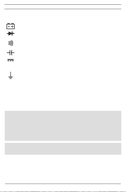
E
Este símbolo en el multímetro BENNING MM P3 indica que el
BENNING MM P3 está equipado con aislamiento de protección (clase de
protección II).
Este símbolo aparece en el display indicando batería descargada.
Este símbolo indica el rango de la función de „prueba de diodo".
Este símbolo indica el rango de la función de „prueba de continuidad". El
zumbador sirve para señalización acústica del resultado.
Este símbolo indica el rango de la función de „prueba de capacidad".
(DC) tensión continua.
(AC) tensión alterna.
Tierra (tensión hacia tierra).
2. Instrucciones de seguridad
El equipo está fabricado y testado conforme a la norma
DIN VDE 0411 parte 1/ EN 61010-1
y salió de fábrica en perfecto estado de seguridad técnica.
Para mantener el equipo en este perfecto estado de seguridad y garantizar
su funcionamiento sin peligro, el usuario debe observar en todo momento las
informaciones y advertencias que se indican en este manual de servicio.
Los medidores deben ser utilizados en circuitos eléctricos de sobretensión de categoría II con un conductor a tierra de 600 V, o de la
categoría de sobretensión III con conductor a tierra 300 V.
Tenga en cuenta que cualquier trabajo en partes e instalaciones
bajo tensión eléctrica son en principio peligrosos. Incluso tensiones bajas de 30 V AC y 60 V DC pueden ser peligrosas para las
personas.
Antes de cada utilización, se debe vericar que el equipo y los
cables a utilizar en las medidas no muestren daños.
Cuando no pueda asegurar el funcionamiento del dispositivo peligro, hay que apagar
el equipo y asegurarse para evitar su accionamiento involuntario.
Se supone que ya no queda garantizado su funcionamiento sin peligro, cuando,
- el equipo o los cables de medida muestran daños visibles,
- cuando el equipo ya no funciona,
- si el dispositivo ha sido almacenado mucho tiempo bajo condiciones desfavorables,
36
03/ 2014
BENNING MM P3

- si el dispositivo ha sufrido esfuerzos debido al transporte.
E
Para evitar peligros
- no tocar las puntas de los cables de medida,
3. Contenido del suministro
Contenido del suministro BENNING MM P3:
3.1 un BENNING MM P3 con dos líneas de medición de seguridad conectadas
fijas, negra y roja (L = 0,6 m; Punta Ø = 2 mm),
3.2 un estuche de protección,
3.3 dos pilas 1,5 V (LR 44), montadas en los multímetros,
3.4 una manual de instrucciones de funcionamiento.
Piezas propensas al desgaste:
- El multímetro BENNING MM P3 se alimentan con dos pilas montadas de 1,5 V,
(LR44).
4. Descripción del dispositivo
Ver g. 1: parte frontal del equipo
Los elementos de señalización y funcionamiento indicados en la gura 1 se
denominan como sigue:
Display dígitosal, para indicar el valor y de rango excedido,
Indicación de la polaridad,
Indicación de la batería, se muestra cuando la batería está descargada,
4
Tecla HOLD, almacenamiento del valor medido,
5
Tecla SELECT, para seleccionar la segunda o la tercera función,
6
Tecla RANGE, conmutación entre rango de medida automático/ manual,
7
Conmutador rotativo, para seleccionar la función a medir,
8
Línea de medición de seguridad (roja), positivo1 conexión para V, Ω, , Hz,
9
Línea de medición de seguridad COM (negra), conexión común para medida
de tensión/ resistencias/ frecuencia/ tasa de impulsos/ capacidad, prueba de
continuidad y de diodos,
1
) Esto se refiere a la indicación automática de polaridad para tensión continua
5. Información general
5.1 Información general del multímetro
5.1.1 El display dígitosal es de cristal líquido de 35/6 dígitosos de 14 mm de
altura con punto decimal. El valor máximo indicado es 5000.
5.1.2 La indicación de polaridad en pantalla es automática. Sólo se indica con
“-” una polarización contraria a la indicada en la definición de la conexión.
5.1.3 El exceso de escala será mostrado con “OL” o “-OL” y algunas veces con
una señal acústica.
¡Atención: no indicación ni avisos en caso de sobrecarga.!
5.1.4 Archivar valores medidos “HOLD”: El resultado de la medición se archiva
pulsando la tecla “HOLD” 4. Simultáneamente, en el display aparece el
37
03/ 2014
BENNING MM P3
símbolo “HOLD”. Pulsando la tecla nuevamente, el equipo vuelve al modo
E
de medición.
5.1.5 La tecla „SELECT” 5 selecciona la segunda o la tercera función de la
posición de interruptor giratorio.
Nota:
La función „%” describe la tasa de impulsos de señales periódicas:
5.1.6 La tecla de rangos “RANGE” 6 sirve para conmutación manual de los
rangos de medición, con indicación simultánea de “AUTO” en el display.
Pulsando la tecla durante 1 segundos aproximadamente, se activa la
selección automática de rangos (indicación “AUTO”).
En la posición de interruptor giratorio ( ), la tecla „RANGE“ tiene una
función de valor relativo „REL ∆“. Pulsando la tecla se guarda el valor de
medición producido y se visualiza la diferencia (Offset) entre el valor de
medición guardado y los valores de medición siguientes. La función de valor
relativo „REL ∆“ hace posible el ajuste a cero del área de capacitancia con
líneas de medición sin contacto. Con una nueva pulsación de la tecla se
vuelve al modo normal.
5.1.7 Los valores nominales de medida de los BENNING MM P3 se realiza 3
veces por segundo
5.1.8 El multímetro BENNING MM P3 se conecta o desconecta por medio del
conmutador rotativo 7. Posición “OFF” para desconectar.
5.1.9
Al cabo de unos 30 minutos, el BENNING MM P3 se apaga automáticamente
(APO, Auto-Power-Off). La desconexión automática puede desactivarse
pulsando la tecla „RANGE“, y conectando simultáneamente el BENNING MM P3
desde la posición „OFF“ del conmutador.
5.1.10 Coeficiente de temperatura del valor medido: 0,2 x (tolerancia de medición
indicada)/ °C < 18 °C ó > 28 °C, relativo al valor existente con una temperatura
de referencia de 23 °C.
5.1.11 Los multímetros BENNING MM P3 se alimentan con dos pilas 1,5 V,
(LR44).
5.1.12 En el display aparece el símbolo de batería , cuando la tensión de
batería es menor a la tensión de trabajo prevista del
BENNING MM P3.
5.1.13 La vida útil de una pila es de unas 100 horas (pila alcalina).
38
03/ 2014
BENNING MM P3
[%] =
T1
T

5.1.14
E
Dimensiones del equipo: (largo x ancho x alto) = 132 x 86 x 19 mm con bolsa
peso del equipo: 130 g con bolsa y baterías
5.1.15 Las puntas de prueba para medida, están protegidas y con tecnología
enchufable de 2 mm. Las líneas de medición de seguridad conectadas
corresponden a la tensión nominal del BENNING MM P3.
6. Condiciones ambientales
- Los multímetros BENNING MM P3 están diseñados para medidas en ambientes
secos,
- Altura barométrica máxima para las medidas: 2000 m,
- Categoría de sobretensión/ categoría de instalación: IEC 60664-1/ IEC 61010-1
→ 300 V categoría III, 600 V categoría II,
- Contaminación clase: 2,
- Clase de protección: IP 30 (DIN VDE 0470-1 IEC/ EN 60529),
Protección IP 30 significa: Primer dígito (3): Protección contra contactos a partes
peligrosas y contra objetos de un diámetro superior a 2,5 mm. Segundo dígito
(0): No protege del agua.
- Temperatura de trabajo y humedad relativa:
Con temperaturas de trabajo entre 0 °C y 30 °C y humedad relativa inferior al 80 %.
Con temperaturas de trabajo entre 31 °C y 40 °C y humedad relativa inferior al 75 %.
Con temperaturas de trabajo entre 41 °C y 50 °C y humedad relativa inferior al 45 %.
- Temperatura de almacenamiento: Los BENNING MM P3 permiten
almacenamiento con temperaturas de - 20 °C hasta + 60 °C (humedad 0 hasta
80 %). Durante el almacenamiento, si este es superior a 1 mes, se deben sacar
las pilas del dispositivo.
7. Especicacioneseléctricas
Nota: La exactitud de las medidas se indica como suma resultando de
- una parte relativa al valor medido y
- un número determinado de dígitos (es decir pasos de dígitos de la última
posición).
Esta exactitud de medidas vale con temperaturas de 18 °C hasta 28 °C y una
humedad relativa inferior al 80 %.
7.1 Rangos de tensión continua (Posición del interruptor: VDC, mVDC)
La resistencia de entrada es de 10 MΩ
Rango de medida Resolución Exactitud de medición Protección de sobrecarga
400 mV 0,1 mV ± (0,7 % del valor medido + 5
4 V 1 mV ± (0,6 % del valor medido + 2
40 V 10 mV ± (0,6 % del valor medido + 2
400 V 100 mV ± (0,6 % del valor medido + 2
600 V 1 V ± (0,7 % del valor medido + 5
dígitos
dígitos
dígitos
dígitos
dígitos
)
600 V
600 V
600 V
600 V
600 V
DC
DC
DC
DC
DC
)
)
)
)
39
03/ 2014
BENNING MM P3

7.2 Rangos de tensión alterna (Posición del interruptor: VAC, Hz, %)
E
La resistencia de entrada es de 10 MΩ en paralelo 100 pF.
Rango de medida Resolución
Exactitud de la medida
en rango de frecuencia 50 Hz - 500 Hz
400 mV 0,1 mV ± (1,5 % del valor medido + 5 Dígitos)
4 V 1 mV ± (0,9 % del valor medido + 5 Dígitos)
40 V 10 mV ± (0,9 % del valor medido + 5 Dígitos)
400 V 100 mV ± (0,9 % del valor medido + 5 Dígitos)
600 V 1 V ± (0,9 % del valor medido + 5 Dígitos)
El valor de medida de los BENNING MM P3 se obtiene mediante la recticación y
mostrado como valor R.M.S.
*1
La exactitud de las medidas están especificadas para curvas senoidales. En
caso de curvas no senoidales, la resolución del display es menor.
7.3 Rango de resistencias (Posición del interruptor: Ω, , )
Protección de sobrecarga para medida de resistencias: 600 V
Rango de medida Resolución Exactitud de medida
400 Ω 0,1 Ω ± (0,9 % del valor medido + 5 Dígitos) 0,4 V
4 kΩ 1 Ω ± (0,9 % del valor medido + 2 Dígitos) 0,4 V
40 kΩ 10 Ω ± (0,9 % del valor medido + 2 Dígitos) 0,4 V
400 kΩ 100 Ω ± (0,9 % del valor medido + 2 Dígitos) 0,4 V
4 MΩ 1 kΩ ± (1,5 % del valor medido + 5 Dígitos) 0,4 V
40 MΩ 10 kΩ ± (1,5 % del valor medido + 5 Dígitos) 0,4 V
7.4 Prueba de diodos y continuidad (Posición del interruptor: Ω, , )
Protección de sobrecarga para: 600 V
El vibrador integrado suena con una resistencia R inferior a 50 Ω.
Rango de medida Resolución
eff
Máxima corriente
1 mV 1,1 mA 1,5 V
medida
*1
Protección de sob-
recarga
eff
Tensión máx. en
circuito abierto
Máxima tensión en circuito
abierto
600 V
600 V
600 V
600 V
600 V
eff
eff
eff
eff
eff
7.5 Rangos de capacidad (Posición del interruptor: )
Condiciones:
Protección de sobrecarga para medida de capacidad: 600 V
Descargar los condensadores y conectarlos conforme la polaridad indicada.
eff
Rango de medida Resolución Exactitud de medida
50 nF 10 pF ± (5,0 % del valor medido + 0,2 nF)*
40
03/ 2014
BENNING MM P3

E
500 nF 100 pF ± (2,9 % del valor medido + 5 Dígitos)
5 µF 1 nF ± (2,9 % del valor medido + 5 Dígitos)
50 µF 10 nF ± (2,9 % del valor medido + 5 Dígitos)
100 µF 100 nF ± (2,9 % del valor medido + 5 Dígitos)
La duración de la medición depende del tamaño del capacitor y puede ser de hasta
20 segundos.
* La exactitud de medición está especicada para valores de medición a partir de
10 nF y previo ajuste a a cero mediante la tecla „RANGE/ REL Δ ( )“ 6.
7.6 Rangos de frecuencia
Protección de sobrecarga para medida de frecuencias: 600 V
7.6.1 Gamas de frecuencias para señales rectangulares
(Posición de interruptor: Hz, %)
Rango de
medida
Resolución
Exactitud de medida para 5 VSS máx.
(señal rectangular)
5 Hz 0,001 Hz ± (0,3 % del valor medido + 5 Dígitos) > 1,0 Vss (rectángulo)
50 Hz 0,01 Hz ± (0,3 % del valor medido + 5 Dígitos) > 1,0 Vss (rectángulo)
500 Hz 0,1 Hz ± (0,3 % del valor medido + 5 Dígitos) > 1,0 Vss (rectángulo)
5 kHz 1 Hz ± (0,3 % del valor medido + 5 Dígitos) > 1,0 Vss (rectángulo)
50 kHz 10 Hz ± (0,3 % del valor medido + 5 Dígitos) > 1,0 Vss (rectángulo)
500 kHz 100 Hz ± (0,3 % del valor medido + 5 Dígitos) > 1,0 Vss (rectángulo)
5 MHz 1 kHz ± (0,3 % del valor medido + 5 Dígitos) > 1,0 Vss (rectángulo)
7.6.2 Indicación de frencuencias para señales sinusoidales (posición de interruptor:
VAC, Hz, %) y pulsación de la tecla „SELECT “:
Exactitud de medición: ± (0,3 % + 5 Digit) válida para tensiones sinusoidales
de hasta 600 V
alterna (VAC) mayor del 50 % del valor final de gama de medición
7.7
Tasa de impulsos para señales rectangulares (Posición del interruptor: Hz, %)
Protección de sobrecarga en medición de relación de tacto: 600 V
Rango de medición Resolución
(10 Hz - 500 Hz) y valor de indicación en gama de tensión
eff
Exactitud de medición 5 VSS máx.
(Señal rectangular, 5 Hz - 5 kHz)
0,1 % - 99,9 % 0,1 % ± (0,5 % del valor medido + 3 Dígitos) > 1,0 Vss (rectángulo)
8. Medir con el BENNING MM P3
8.1 Preparando la medida
Usar y almacenar el multímetro BENNING MM P3 sólo con las temperaturas de
trabajo y de almacenamiento indicadas
No exponer el dispositivo a una radiación solar continua.
- Las líneas de medición de seguridad negra y roja responde a las normas
41
03/ 2014
BENNING MM P3
eff
eff
Sensibilidad
Sensibilidad
(30 % ≤ % ≤ 70 %)

vigentes, siempre que no
E
- Las líneas de medición de seguridad negra y roja conectadas deben de
protegerse de la suciedad.estén deterioradas.
- Comprobar que el aislamiento de las puntas y cables de prueba. Si el aislamiento
es defectuoso, eliminar en seguida dichas multímetro.
- Comprobar la continuidad de los cables de medida. Si se encontrarse interrumpido
el hilo conductor de dicho cable, eliminar en multímetro estos elementos.
- Antes de seleccionar otra función mediante el conmutador de rotativo 7, hay
que retirar las conexiones de medida del punto de que se está midiendo.
- Fuentes de fuerte interferencia en las inmediaciones del multímetro
BENNING MM P3 pueden causar inestabilidad en la indicación de valores y
producir errores de medición.
8.2 Medida de tensiones
¡No sobrepasar el valor de tensión máxima con respecto a tierra
permitido! ¡Peligro de tensión eléctrica!
La tensión máxima que se puede conectar a:
- Línea de medición de seguridad COM (negra)
- Línea de medición de seguridad (roja) para V, Ω, , Hz
del multímetro BENNING MM P3 a tierra, es de 600 V.
- Mediante el conmutador rotativo 7 seleccionar la función deseada (V AC) ó (V
DC) en el BENNING MM P3.
- Poner el otro extremo de las puntas de prueba sobre el los puntos
que se desean medir, leer el valor medido en el display del
BENNING MM P3.
- En la posición de interruptor giratorio (VAC), se puede efectuar con la tecla
„SELECT“ 5 el cambio a medición de frecuencia (pulsar la tecla una vez) o
medición de tasa de impulsos (pulsar la tecla dos veces).
Nota:
En las áreas de tensión pequeñas, estando abiertas las líneas de medición de
seguridad, puede que no se produzca la indicación de voltaje cero, debido a
interferencias. Comprobar el funcionamiento del BENNING MM P3 mediante
cortocircuito de las puntas de medición.
ver g 2: medida de tensión continua
ver g 3: medida de tensión alterna
8.3 Medida de resistencias
- Mediante el conmutador rotativo 7 seleccionar la función deseada (Ω, , )
del BENNING MM P3.
- Colocar las puntas opuestas de las puntas de prueba a los puntos
de medida deseados, leer el valor medido en el display del
BENNING MM P3.
ver g 4: medida de resistencia
9
8
42
03/ 2014
BENNING MM P3

8.4 Prueba de diodos
E
- Mediante el conmutador rotativo 7 seleccionar la función deseada (Ω, , )
en el multímetro BENNING MM P3.
- Con la tecla „SELECT“ 5 efectuar en el BENNING MM P3 la conmutación a
comprobación de diodos ( ) (pulsar la tecla una vez)
- Conectar las puntas opuestas de las puntas de prueba al diodo a medir, leer el
valor medido en el display del multímetro BENNING MM P3.
- Para un diodo de Silicio normal, aplicado en dirección de flujo, se indica una
tensión de flujo de entre 0,400 V y 0,900 V. El mensaje “000” en display indica
un cortocircuito en el diodo, el mensaje “OL” en display indica una discontinuidad
dentro del diodo.
- Un diodo en sentido de bloqueo es indicado con “OL”. Estando defectuoso el
diodo, se indica “000” u otros valores.
ver g 5: prueba de diodos
8.5 Prueba de continuidad con vibrador
- Mediante el conmutador rotativo 7 seleccionar la función deseada (Ω, , )
en el multímetro BENNING MM P3.
- Con la tecla „SELECT“ 5 efectuar en el BENNING MM P3 la conmutación a
comprobación de continuidad ( ) (pulsar la tecla dos veces).
- Conectar los extremos opuestos de las puntas de prueba a los puntos a medir.
- Cuando la resistencia entre los puntos de medición baja de 50 Ω, suena el
zumbador instalado en el BENNING MM P3.
ver g 6: prueba de continuidad con vibrador
8.6 Medida de capacidad
Antes de efectuar cualquier medida de capacidad es imprescindible
descargar los condensadores totalmente. No aplicar jamás tensión a las hembrillas para medida de capacidad. !Puede destruir el
equipo! Un equipo dañado puede suponer una fuente de peligro de
tensión eléctrica!
- Mediante el conmutador rotativo 7 seleccionar la función ( ) deseada en el
multímetro BENNING MM P3.
- Averiguar la polaridad del condensador y descargarlo totalmente.
- En caso necesario, efectuar el ajuste a cero mediante la tecla „RANGE/ REL Δ
( )“ 6.
- Conectar los extremos opuestos de las puntas de prueba al condensador
descargado y según su polaridad, leer el valor medido en el display del
BENNING MM P3.
ver g 7: medida de capacidad
8.7 Medida de frecuencia
- Para medir señales restangulares de hasta 5 VSS máx., seleccionar con el
interruptor giratorio 7 la función deseada (Hz, %).
- Para medir señales sinusoidales de hasta 600 V
43
03/ 2014
BENNING MM P3
, seleccionar con el interruptor
eff

E
giratorio 7 la función deseada (VAC, Hz, %) y realizar con la tecla „SELECT“ la
conmutación a medición de frecuencia (Hz).
- Comprobar la sensibilidad mínima para medidas de frecuencia del
BENNING MM P3
- Conectar los extremos opuestos de las puntas de prueba a los puntos a medir,
leer el valor medido en el display del multímetro BENNING MM P3.
ver g 8: medida de frecuencia/ de la relación de tacto
8.8 Medición de la tasa de impulsos
- Seleccionar con el interruptor giratorio 7 la función deseada (Hz, %) en el
BENNING MM P3.
- Con la tecla „SELECT“ 5 en el BENNING MM P3 efectuar el cambio a medición
de tasa de impulsos (%) (pulsar la tecla una vez).
- Poner en contacto las líneas de medición de seguridad con los puntos de
medición, leer el valor de medición en la visualización dígitosal en el
BENNING MM P3.
ver g 8: Medición de frecuencia/ de tasa de impulsos
9. Mantenimiento
¡Antes de abrir el multímetro BENNING MM P3, asegurarse que el
dispositivo está libre de tensión!
¡Peligro de tensión eléctrica!
Trabajar en los multímetros BENNING MM P3 abierto y bajo tensión queda exclusivamente en manos de personal eléctrico especializado, que debe tomar medidas especiales para evitar accidentes eléctricos.
Por lo tanto, asegúrese que los multímetros BENNING MM P3 están libres de tensión
antes de abrirlo:
- Primero quitar las bornas de prueba de cualquier punto que estuviesen
conectadas.
- Posicionar el conmutador rotativo 7 en posición „OFF“.
9.1 Guardar seguro el equipo
En determinadas condiciones, no se puede garantizar el funcionamiento seguro del
multímetro BENNING MM P3; por ejemplo en caso de:
- Daños visibles en la carcasa y en las líneas de medición de seguridad,
- Resultados de medidas incorrectas,
- Huellas visibles como consecuencia de almacenamiento durante largo tiempo
bajo condiciones inadmisibles y
- Huellas visibles resultantes de un transporte inadecuado.
En dichos casos, se debe desconectar inmediatamente el multímetro
BENNING MM P3, desconectarlo de los puntos de medida y guardarlo para evitar
su utilización.
9.2 Limpieza
Limpiar la supercie de la carcasa con un paño limpio y seco (excepcionalmente con
44
03/ 2014
BENNING MM P3

paños especiales de limpieza). No utilice disolventes y / o abrasivos para limpiar el
E
dispositivo. Asegúrese que el compartimento de la pila y los contactos no se contaminen
con el electrolito que pueda salir de la pila.
En caso de aparecer restos de electrolito o residuos blancos en el compartimento de la
pila o en sus terminales, limpiar éstos también con un paño seco y cambiar la pila.
9.3 Cambio de pila
¡Antes de abrir el multímetro BENNING MM P3, desconectar el
equipo de cualquier punto de medida, debe estar libre de tensión!
¡Peligro de tensión eléctrica!
El multímetro BENNING MM P3 se alimenta con dos pilas 1,5 V (LR 44).
Si fuese necesario cambiar la pila (ver gura 9), esto sucede cuando en el display
aparece el símbolo de la batería .
Para el cambio de pila, siga las siguientes instrucciones:
- Desconectar las puntas de prueba de los puntos de medida.
- Colocar el conmutador rotativo 7 en posición „OFF“.
- Colocar el BENNING MM P3 sobre el lado frontal y soltar los tornillos del fondo
de la carcasa.
- Levantar con cuidado el fondo de la carcasa.
¡No soltar ningún tornillo del circuito impreso en el multímetro
BENNING MM P3!
- Sacar las pilas descargadas del compartimento del dispositivo.
- Colocar las baterías nuevas, con la polaridad correcta, en el compartirmento. El
polo positivo indica hacia arriba.
- Encajar el fondo de la carcasa sobre la parte superior de la carcasa y apretar de
nuevo los tornillos.
ver g 9: cambio de pila
Aporte su granito a la protección del medio ambiente! Las pilas no
son basura doméstica. Se pueden entregar en un punto de recogida
de pilas usadas o residuos especiales. Infórmese, por favor, en su
municipio.
9.4 Calibración
Para obtener las exactitudes indicadas en los resultados de las medidas, el
dispositivo debe ser calibrado en intervalos regulares por nuestra servicio técnico.
Recomendamos que el intervalo de calibrado sea de una vez al año. Para ello, enviar
el equipo a la siguiente dirección:
Benning Elektrotechnik & Elektronik GmbH & Co. KG
Service Center
Robert-Bosch-Str. 20
D - 46397 Bocholt
45
03/ 2014
BENNING MM P3

10. Empleo del estuche de protección
E
Se pueden proteger las líneas de medición de seguridad enrollándolas y sujetándolas con el cierre de velcro dentro del estuche de protección.
ver g 10: Empleo del estuche de protección
11. Protección ambiental
Para preservar el medio ambiente, al nal de la vida útil de su producto,
deposítelo en los lugares destinado a ello de acuerdo con la legislación
vigente.
46
03/ 2014
BENNING MM P3

Návodkpoužití
BENNING MM P3
Digitální multimetr pro
- měření stejnosměrného napětí
- měření střídavého napětí
- měření odporu
- zkoušky diod
- zkoušky obvodů
- měření kapacity
- měření frekvence
- měření střídy impulzů
Obsah
1. Pokynyprouživatele
2. Bezpečnostnípokyny
3. Obsah dodávky
4. Popispřístroje
5. Všeobecné údaje
6. Podmínkyprostředí
7. Elektrické údaje
8. MěřenísBENNINGMMP3
9. Údržba
10. Použitíochrannéhopouzdra
11. Ochranaživotníhoprostředí
1. Pokynyprouživatele
Tento návod je určen pro
- odborníky v oboru elektro a
- poučené osoby.
BENNING MM P3 je určen pro měření suchém prostředí. Nesmí být nasazen
v instalacích s napětím vyšším než 600 V DC nebo AC (více informací v oddílu 6.
„pracovní prostředí„).
V tomto návodu a na BENNING MM P3 budou používány následující symboly:
Varování před elektrickým nebezpečím!
Je u umístěno před instrukcemi, kterých je nutno dbát pro zamezení
ohrožení osob.
Pozor – sledujte dokumentaci!
Tento symbol se vyskytuje tam, kde je nutno zvlášť pečlivě sledovat
instrukce v návodu, pro zamezení ohrožení osob.
47
03/ 2014
BENNING MM P3
Tento symbol na BENNING MM P3 znamená, že
BENNING MM P3 je vybaven izolací třídy II.
Tento symbol se zobrazí při vybitých baterií.
Tento symbol značí režim „test diod“.
Tento symbol značí režim „test obvodů“.
Bzučák slouží k akustickému oznámení průchodu proudu.
Tento symbol značí režim „měření kapacity“.
(DC) stejnosměrný napětí.
(AC) střídavý napětí.
Zem (napětí proti zemi).
2. Bezpečnostnípokyny
Tento přístroj byl zkonstruován a sestaven dle normy
DIN VDE 0411 Teil 1/ EN 61010-1
a opustil výrobní závod v bezvadném a bezpečném stavu.
Pro udržení tohoto stavu a bezpečný provoz se musí uživatel řídit instrukcemi a
varováními, uvedenými v tomto návodě.
PřístrojsmíbýtjenvinstalacíchsnapětímkategorieIIsmax.600V
proti zemi nebo vinstalacích snapětím kategorieIII smax. 300V
proti zemi.
Dbejte na to, že práce na dílech pod napětím je ze zásady
nebezpečná.Jižnapětíod 30V AC a 60V DC mohoubýtčlověku
smrtelněnebezpečná.
Předkaždým uvedenímdoprovozu otestujetepřístroja vodičena
možnápoškození.
Pokud lze předpokládat, že bezpečný provoz není dále možný, přístroj dále
nepoužívejte a zabraňte jiným osobám v jeho použití.
Lze předpokládat, že bezpečný provoz není dále možný, když:
- když přístroj nebo měřící vodiče vykazují viditelná poškození,
- když přístroj nepracuje,
- po dlouhém skladování v nevyhovujících podmínkách,
- po obtížné přepravě.
48
03/ 2014
BENNING MM P3

Provyloučeníohrožení
- nedotýkejteseholýchšpičekměřícíhovedení,
3. Rozsah dodávky
Součástí dodávky přístroje BENNING MM P3 je:
3.1 jeden měřicí přístroj BENNING MM P3 se dvěma napevno připojenými
bezpečnostními měřicími kabely, černým a červeným (L = 0,6 m; špička
Ø = 2 mm),
3.2 jedno ochranné pouzdro
3.3 dvě 1,5 V baterie (LR 44) vložené do přístroje
3.4 návod
Upozornění na opotřebovatelné součástky:
- BENNING MM P3 je napájen dvěma 1,5-V bateriemi (LR 44).
4. Popispřístroje
viz obr. 1: Přední strana přístroje
Na obr. 1 zobrazené ukazatele a ovládací prvky jsou popsány dále:
Digitální displej, pro naměřenou hodnotu a ukazatel překročení měřícího
rozsahu
Zobrazení polarity
Ukazatel stavu baterie, značí vybitou baterie
4
TlačítkoHOLD, ukládání naměřených hodnot
5
TlačítkoSELECT,pro volbu druhé a třetí funkce,
6
TlačítkoRANGE, přepínání automatického nebo manuálního měřícího rozsahu
7
Otočnýfunkčnívolič, pro volbu měřící funkce
8
Bezpečnostníměřicíkabel(červený) (pozitivní1), pro V, Ω, , Hz,
9
COM-bezpečnostní měřicí kabel (černý), společné připojení pro měření,
napětí, odpor, frekvenci, střídy impulzů, kapacitu, zkoušku obvodu a test diod
1) k tomuto se váže automatický ukazatel polarity při stejnosměrném napětí
5. Všeobecné údaje
5.1 Všeobecné údaje k multimetru
5.1.1 Digitální displej 35/6 místný, na principu tekutých krystalů, výška číslic
14 mm s desetinnou čárkou, max. hodnota je 5000
5.1.2 Ukazatel polarity působí automaticky. Zobrazuje se pouze pólování proti
definici připojení s „-“.
5.1.3 Překročení měřícího rozsahu bude oznámeno zobrazením „OL“ nebo „-OL“
a částečně i akustickým varováním.
Pozor, žádná indikace a varování při přetížení!
5.1.4 Ukládání naměřených hodnot „HOLD“: stiskem tlačítka „HOLD“ 4 je možno
uložit naměřenou hodnotu. Na displeji se současně zobrazí symbol „HOLD“.
Další stisk tlačítka přepne přístroj do měřícího módu.
5.1.5 Tlačítko „SELECT” 5 nastavuje druhou nebo třetí funkci pozice otočného
spínače.
49
03/ 2014
BENNING MM P3

Upozornění:
Funkce „%” popisuje střídu impulzů periodických signálů:
5.1.6 Rozsahové tlačítko „RANGE“ 6 slouží k přepínání mezi manuální a
automatickou volbou rozsahu při současném zobrazení „AUTO“ na displeji.
Delším stiskem (1 vteřiny) dojde k přepnutí na automatkou volbu rozsahu
(„AUTO“ na displeji).
V pozici otočného přepínače ( ) má tlačítko „RANGE“ funkci relativní
hodnoty „REL ∆“. Po stlačení tlačítka se stávající hodnota uloží a zobrazí
se rozdíl (Offset) mezi uloženou hodnotou a následujícími naměřenými
hodnotami. Funkce relativní hodnoty „REL ∆“ umožňuje při rozpojení
měřicích vodičů vynulování rozsahu kapacity. Dalším stiskem tlačítka se
dostanete do normálního režimu.
5.1.7 BENNING MM P3 měří nominálně 3 x za vteřinu.
5.1.8 BENNING MM P3 se vypíná otočením otočného voliče 7 do polohy „OFF“.
5.1.9 BENNING MM P3 se po cca. 30 minutách automaticky (APO, Auto-Power-
Off). Automatické vypnutí lze deaktivovat tím, že se stiskne tlačítko „RANGE“
a zároven se BENNING MM P3 zapne ze spínací polohy „OFF“.
5.1.10 Teplotní koeficient měření: 0,2 x (udávaná přesnost měření)/ °C < 18 °C oder
> 28 °C, vztažená na hodnotu při referenční teplotě 23 °C.
5.1.11 BENNING MM P3 je napájen 1,5 V bateriemi (LR 44).
5.1.12 Pokud napětí baterie poklesne pod minimální pracovní hodnotu, na displeji
se objeví symbol baterie .
5.1.13 Životnost baterie obnáší asi 100 hodin (alkalické baterie).
5.1.14 Rozměry přístroje: (D x Š x H) = 132 x 86 x 19 mm se pouzdro
Váha přístroje: 130 g se pouzdro a baterii
5.1.15 Měřící bezpečnostní kabely jsou vybaveny 2 mm konektory. Připojené
bezpečnostní měřicí kabely odpovídají jmenovitému napětí přístroje
BENNING MM P3.
6. Podmínkyprostředí
- BENNING MM P3 je určen pro měření v suchém prostředí,
- Maximální nadmořská výška při měření: 2000 m,
- Kategorie přepětí / nastavení: IEC 60664-1/ IEC 61010-1 → 300 V kategorie III;
600 V kategorie II
50
03/ 2014
BENNING MM P3
[%] =
T1
T

- Stupeň znečistitelnosti: 2,
- Krytí: IP 30 DIN VDE 0470-1 IEC/EN 60529,
Význam IP 30: Ochrana proti malým cizím předmětům, proti dotyku nářadím,
drátem a podobně s průměrem > 2,5 mm, (3 - první číslice). Žádná ochrana před
vodou, (0 - druhá číslice).
- Pracovní teplota a relativní vlhkost:
Při teplotě od 0 °C do 30 °C: relativní vlhkost menší 80 %,
Při teplotě od 31 °C do 40 °C: relativní vlhkost menší 75 %,
Při teplotě od 41 °C do 50 °C: relativní vlhkost menší 45 %,
- Skladovací teploty: BENNING MM P3 může být skladován při teplotách od
- 20 °C do + 60 °C (vlhkost 0 až 80 %). Baterie musí být vyňaty.
7. Elektrické údaje
Poznámka: Přesnost měření se udává jako součet
- relativního podílu měřené hodnoty a
- počtu číslic (t.j. zobrazení čísla na posledních místech).
Přesnost měření platí při teplotách od 18 °C do 28 °C a při relativní vlhkosti menší
než 80 %.
7.1 Rozsahystejnosměrnéhonapětí(Pozice přepínače: VDC, mVDC)
Vstupní odpor je 10 MΩ.
Měřící rozsah Rozlišení Přesnost Přetížitelnost
400 mV 0,1 mV ± (0,7 % naměřené hodnoty + 5
4 V 1 mV ± (0,6 % naměřené hodnoty + 2
40 V 10 mV ± (0,6 % naměřené hodnoty + 2
400 V 100 mV ± (0,6 % naměřené hodnoty + 2
600 V 1 V ± (0,7 % naměřené hodnoty + 5
7.2 Rozsahystřídavéhonapětí(Pozice přepínače: VAC, Hz, %)
Vstupní odpor je 10 MΩ paralelně 100 pF.
Měřící rozsah Rozlišení
Přesnost *1
ve frekvenčním rozsahu 50 Hz - 500 Hz
400 mV 0,1 mV ± (1,5 % naměřené hodnoty + 5
4 V 1 mV ± (0,9 % naměřené hodnoty + 5
40 V 10 mV ± (0,9 % naměřené hodnoty + 5
400 V 100 mV ± (0,9 % naměřené hodnoty + 5
600 V 1 V ± (0,9 % naměřené hodnoty + 5
Naměřená hodnota u BENNING MM P3 je měřena jako průměr a zobrazena jako
efektivní hodnota.
*1 Přesnost měření je specifikována pro. Při nesinusové křivce je hodnota na
ukazateli nepřesná.
51
03/ 2014
BENNING MM P3
číslic
číslic
číslic
číslic
číslic
číslic
číslic
číslic
číslic
číslic
)
)
)
)
)
)
)
)
)
)
600 V
DC
600 V
DC
600 V
DC
600 V
DC
600 V
DC
Přetížitelnost
600 V
eff
600 V
eff
600 V
eff
600 V
eff
600 V
eff
7.3 Rozsahy odporu (Pozice přepínače: Ω, , )
Ochrana před přetížením: 600 V
Měřící rozsah Rozlišení Přesnost
400 Ω 0,1 Ω ± (0,9 % naměřené hodnoty + 5
4 kΩ 1 Ω ± (0,9 % naměřené hodnoty + 2
40 kΩ 10 Ω ± (0,9 % naměřené hodnoty + 2
400 kΩ 100 Ω ± (0,9 % naměřené hodnoty + 2
4 MΩ 1 kΩ ± (1,5 % naměřené hodnoty + 5
40 MΩ 10 kΩ ± (1,5 % naměřené hodnoty + 5
7.4 Měřenídiodazkouškaobvodů(Pozice přepínače: Ω, , )
Ochrana před přetížením: 600 V
Zabudovaný bzučák zazní při odporu R menším než 50 Ω.
Měřící rozsah Rozlišení
7.5 Kapacitní rozsahy (Pozice přepínače: )
Podmínky: kondenzátory vybít a připojit na odpovídající polaritu.
Ochrana před přetížením: 600 V
Měřící rozsah Rozlišení Přesnost
50 nF 10 pF ± (5,0 % naměřené hodnoty + 0,2 nF)*
500 nF 100 pF ± (2,9 % naměřené hodnoty + 5
5 µF 1 nF ± (2,9 % naměřené hodnoty + 5
50 µF 10 nF ± (2,9 % naměřené hodnoty + 5
100 µF 100 nF ± (2,9 % naměřené hodnoty + 5
Doba měření závisí na velikosti kondenzátoru a může činit až 20 sekund.
* Přesnost měření je dána pro měřené hodnoty od 10 nF a podmíněna předchozím
vynulováním tlačítkem „RANGE/ REL Δ ( )“ 6.
7.6 Frekvenčnírozsahy
Ochrana před přetížením při měření frekvence: 600 V
7.6.1 Frekvenční rozsahy pro obdélníkové signály (poloha spínače: Hz, %)
Měřící rozsah Rozlišení
5 Hz 0,001 Hz ± (0,3 % naměřené hodnoty + 5
52
03/ 2014
eff
eff
Napětí při chodu
naprázdno
Napětí při chodu napráz-
číslic
) 0,4 V
číslic
) 0,4 V
číslic
) 0,4 V
číslic
) 0,4 V
číslic
) 0,4 V
číslic
) 0,4 V
Naprázdno
dno
1 mV 1,1 mA 1,5 V
eff
číslic
číslic
číslic
číslic
eff
Měřící přesnost pro 5 VSS max.
(obdélníkový signál)
číslic
) > 1,0 Vss (obdélník)
BENNING MM P3
)
)
)
)
Citlivost

50 Hz 0,01 Hz ± (0,3 % naměřené hodnoty + 5
500 Hz 0,1 Hz ± (0,3 % naměřené hodnoty + 5
5 kHz 1 Hz ± (0,3 % naměřené hodnoty + 5
50 kHz 10 Hz ± (0,3 % naměřené hodnoty + 5
500 kHz 100 Hz ± (0,3 % naměřené hodnoty + 5
5 MHz 1 kHz ± (0,3 % naměřené hodnoty + 5
7.6.2 Ukazatel kmitočtu pro sinusové signály (poloha spínače: VAC, Hz, %) a
stisknutí tlačítka „SELECT“:
Měřící přesnost: ± (0,3 % + 5 číslic) platné pro sinusová napětí do 600 V
(10 Hz - 500 Hz) a indikované hodnoty v rozsahu střídavého napětí (VAC)
větší než 50 % koncové hodnoty měřícího rozsahu
7.7 Klíčovacípoměrproobdélníkovésignály(Pozice přepínače: Hz, %)
Ochhrana před přetížením při měření tlačítkovýchh poměrů: 600 V
Měřící rozsah Rozlišení
0,1 % - 99,9 % 0,1 % ± (0,5 % naměřené hodnoty + 5 číslic) > 1,0 Vss (obdélník)
8. MěřenísBENNINGMMP3
8.1 Přípravanaměření
Používejte a skladujte BENNING MM P3 jen za předepsaných skladovacích a
pracovních teplotních podmínek, zabraňte dlouhodobému slunečnímu osvitu.
- Připojené černé a červené bezpečnostní měřicí kabely, pokud jsou nepoškozené,
splňují platné předpisy.
- Připojené černé a červené bezpečnostní měřicí kabely musí být chráněny před
znečištěním. Jestliže je vodič v bezpečnostním měřicím kabelu přerušen, je
nutno přístroj ihned vyřadit.
- Překontrolujete izolaci na bezpečnostních měřících kabelech. Pokud je
poškozená, okamžitě je vyměňte.
- Překontrolujete průchodnost bezpečnostních měřících kabelů. Pokud jsou vodiče
poškozeny, okamžitě je vyměňte.
- Než změníte otočným voličem 7 funkci, odpojte bezpečnostní měřící kabely od
měřeného místa.
- Silná rušení v blízkosti BENNING MM P3 mohou vést k nestabilitě zobrazení a k
chybám měření.
8.2 Měřenínapětí
Dbejtemaximálníhonapětíprotizemi!
Nebezpečíúrazuelektrickýmproudem!
Nejvyšší napětí, povolené na
9
- COM
53
03/ 2014
Měřící přesnost do 5 VSS max.
(obdélníkový signál, 5 Hz - 5 kHz)
BENNING MM P3
číslic
) > 1,0 Vss (obdélník)
číslic
) > 1,0 Vss (obdélník)
číslic
) > 1,0 Vss (obdélník)
číslic
) > 1,0 Vss (obdélník)
číslic
) > 1,0 Vss (obdélník)
číslic
) > 1,0 Vss (obdélník)
eff
(30 % ≤ % ≤ 70 %)
Citlivost
eff
- V, Ω, , Hz
přístroje BENNING MM P3 je 600 V proti zemi.
- Otočným voličem 7 zvolit na BENNING MM P3 požadovanou funkci (V AC)
nebo (V DC).
- Měřící kabely spojit s měřenými body, na displeji odečíst naměřenou hodnotu.
- V pozici otočného přepínače (VAC) je možno tlačítkem „SELECT“ 5 provádět
přepínání na měření frekvence (stisknout tlačítko jednou) popř. měření střídy
impulzů (stisknout tlačítko dvakrát).
Upozornění:
V oblastech nízkého napětí může při rozpojení bezpečnostních měřicích kabelů
dojít k rušení a k posunu nulování. Je třeba přístroj BENNING MM P3 zkontrolovat
zkratováním měřicích špiček.
Viz. obr. 2: Měření stejnosměrného napětí
Viz. obr. 3: Měření střídavého napětí
8.3 Měřeníodporu
- Otočným voličem 7 na BENNING MM P3 zvolit požadovanou funkci (Ω, , ).
- Měřící kabely spojit s měřenými body, na displeji odečíst naměřenou hodnotu.
Viz. obr. 4: Měření odporu
8.4 Test diod
- Otočným voličem 7 zvolit požadovanou funkci
- Tlačítkem „SELECT“ 5 přepněte přístroj BENNING MM P3 na režim kontroly
diod ( ) (tlačítko stiskněte jednou).
- Měřící kabely spojit s měřenými body, na displeji odečíst naměřenou hodnotu.
- Pro běžnou křemíkovou diodu v propustném směru bude napětí mezi 0,400 V a
0,900 V. Hodnota “000“ značí zkrat v diodě, hodnota „OL“ značí přerušení diody.
- V nepropustném směru značí hodnota “OL“ diodu bez vady. Pokud je dioda
vadná, budou zobrazeny hodnoty „000“ nebo jiné.
Viz. obr. 5: Test diod
8.5 Zkouškaobvodusebzučákem
- Otočným voličem 7 zvolit požadovanou funkci
- Tlačítkem „SELECT“ 5 přepněte přístroj BENNING MM P3 na režim kontroly
průchodu ( ) (tlačítko stiskněte dvakrát).
- Měřící kabely spojit s měřenými body.
- Jestliže je odpor mezi měřicími body menší než 50 Ω, ozve se bzučák zabudovaný
v přístroji BENNING MM P3.
Viz. obr. 6: Zkouška obvodu se bzučákem
8
(Ω, , ).
(Ω, , ).
54
03/ 2014
BENNING MM P3

8.6 Měřeníkapacity
Kondenzátorypředměřenímkapacitydokonalevybít!
Přiměřeníkapacitynikdynepřikládat nazdířkynapětí!Jinakmůže
dojítk poškození přístroje! Odpoškozenéhopřístroje může hrozit
nebezpečíúrazuelektrickýmproudem!
- Otočným voličem 7 zvolit požadovanou funkci ( ).
- Zjistěte polaritu kondenzátorů a dokonale je vybijte.
- Případně proveďte vynulování ukazatele tlačítkem „RANGE/ REL Δ ( )“
- Měřící kabely spojit s měřenými body při zachování polarity, na displeji odečíst
naměřenou hodnotu.
Viz. obr. 7: Měření kapacity
8.7 Měřenífrekvence
- Pro měření obdélníkových signálů do 5 VSS max. zvolit pomocí otočného přepí-
nače 7 požadovanou funkci (Hz, %).
- Pro měření sinusových signálů do 600 V
požadovanou funkci (VAC, Hz, %) a pomocí tlačítka „SELECT“ provést přepnutí
na měření kmitočtu (Hz).
- Dbejte na minimální citlivost pro měření frekvence!
- Měřící kabely spojit s měřenými body, na displeji odečíst naměřenou hodnotu.
Viz. obr. 8: Měření frekvence/ tlačítkovýchh poměrů
8.8 Měřenístřídyimpulzů
- Otočným přepínačem 7 navolte požadovanou funkci (Hz, %) na přístroji
BENNING MM P3.
- Tlačítkem „SELECT“ 5 přístroje BENNING MM P3 přepněte na měření střídy
impulzů (%) (tlačítko stiskněte jednou).
- Spojte bezpečnostní měřicí kabely s měřicími body, naměřenou hodnotu
odečtěte na digitálním ukazateli přístroje BENNING MM P3.
Viz obr. 8: Měření frekvence/ střídy impulzů
9. Údržba
PředotevřenímBENNINGMMP3odpojteodnapětí!
Nebezpečíúrazuelektrickýmproudem!
PrácenaotevřenémBENNINGMMP3podnapětímjsouvyhrazenyodborníkům,
kteřípřitommusídbátzvýšenéopatrnosti.
Oddělte BENNING MM P3 od napětí, než přístroj otevřete:
- Odpojte oba měřící kabely od měřeného objektu.
- Otočným spínačem 7 zvolte funkci „OFF“.
9.1 Zajištěnípřístroje
Za určitých podmínek nemůže být bezpečnost při používání BENNING MM P3
zajištěna, například při:
- Viditelné poškození krytu a bezpečnostních měřicích kabelů,
55
03/ 2014
BENNING MM P3
zvolit pomocí otočného přepínače 7
eff
6.

- Chybách při měření,
- Zřejmých následcích delšího chybného skladování a
- Zřejmých následcích špatného transportu.
V těchto případech BENNING MM P3 ihned vypněte, odpojte od měřených bodů a
zajistěte, aby přístroj nemohl být znovu použit jinou osobou.
9.2 Čištění
Kryt přístroje čistěte opatrně čistým a suchým hadříkem (výjimku tvoří speciální
čistící ubrousky). Nepoužívejte žádná rozpouštědla ani čistící prostředky. Zejména
dbejte toho, aby místo pro baterie ani bateriové kontakty nebyly znečištěny vyteklým
elektrolytem. Pokud k vytečení elektrolytu dojde nebo je bateriová zásuvka znečištěna
bílou úsadou, vyčistěte je také čistým a suchým hadříkem.
9.3 Výměnabaterií
PředotevřenímBENNINGMMP3odpojteodnapětí!
Nebezpečíúrazuelektrickýmproudem!
BENNING MM P3 je napájen dvěma zabudovanými 1,5 V bateriemi (LR 44).
Baterie vyměňte (viz. obr. 9), pokud se na displeji objeví symbol baterie .
Takto vyměníte baterie:
- Odpojte oba měřící kabely od měřeného objektu.
- Otočným spínačem 7 zvolte funkci „OFF“
- Přístroj BENNING MM P3 položte čelní stranou na podložku a uvolněte šrouby
ze dna krytu.
- Dno krytu opatrně zvedněte.
Šetřeteživotníprostředí!Baterienesmídoběžnéhodomovníhood-
padu!Vyhazujtebateriejennamístechktomuurčených.
- Vyjměte vybité baterie z bateriové schránky.
- Nové baterie vložte na místo s ohledem na předepsanou polaritu, kladný pól míří
vzhůru.
- Přitlačte dno krytu na horní část krytu, až spoje zacvaknou a opět šrouby
zašroubujte.
Viz. obr. 9: Výměna baterií
9.4 Kalibrace
Pro udržení deklarované přesnosti měření musí být přístroj pravidelně kalibrován.
Doporučujeme jednou ročně. Zašlete přístroj na adresu:
Benning Elektrotechnik & Elektronik GmbH & Co. KG
Service Center
Robert-Bosch-Str. 20
D - 46397 Bocholt
56
03/ 2014
BENNING MM P3

10.Použitíochrannéhopouzdra
Bezpečnostní měřicí kabely můžete bezpečně uchovat tak, že je svinete a upevníte
suchým zipem uvnitř ochranného pouzdra.
Viz obr. 10: Použití ochranného pouzdra
11. Ochranaživotníhoprostředí
Po ukončení životnosti přístroje prosím předejte přístroj příslušným sběrným
místům na likvidaci.
57
03/ 2014
BENNING MM P3

Betjeningsvejledning
BENNING MM P3
Digital-multimeter til
- Jævnspændingsmåling
- Vekselspændingsmåling
- Modstandsmåling
- Diodetest
- Gennemgangstest
- Kapacitansmåling
- Frekvensmåling
- Impulsforholdsmåling
Indholdsfortegnelse
1. Brugeranvisninger
2. Sikkerhedsanvisninger
3. Leveranceomfang
4. Apparatbeskrivelse
5. Generelle oplysninger
6. Omgivelsesbetingelser
7. Elektriske oplysninger
8. Måling med BENNING MM P3
9. Vedligeholdelse
10. Anvendelse af beskyttelsesetuiet
11. Miljøbeskyttelse
1. Brugeranvisninger
Denne betjeningsvejledning henvender sig til
- elektrikere
- elektroteknikere.
BENNING MM P3 er beregnet til måling i tørre omgivelser. Det må ikke indskydes
i strømkredse med større mærkespænding end 600 V DC eller 600 V AC (nærmere
herom i afsnit 6 “Omgivelsesbetingelser”).
I betjeningsvejledningen og på BENNING MM P3 anvendes følgende symboler:
Advarsel mod elektrisk fare!
Står før anvisninger, der skal følges for at undgå menneskelige risici.
NB: Dokumentationen skal følges!
Symbolet angiver, at betjeningsvejledningens anvisninger skal følges for
at undgå risici.
58
03/ 2014
BENNING MM P3

Dette symbol på BENNING MM P3 betyder, at BENNING MM P3 er udført
dobbeltisoleret (beskyttelsesklasse II).
Dette symbol fremkommer i displayet for et aadet batteri.
Dette symbol kendetegner området “diodetest”.
Dette symbol kendetegner området “gennemgangstest”.
brummeren tjener til afgivelse af det akustiske resultat.
Dette symbol kendetegner området “kapacitanstest”.
(DC) Jævnspænding.
(AC) Vekselspænding.
Jord (spænding mod jord).
2. Sikkerhedsanvisninger
Apparatet er testet og bygget ig.
DIN VDE 0411 Del 1/ EN 61010-1
og har forladt fabrikken i en sikkerhedsteknisk fejlfri tilstand.
For at opretholde denne tilstand og sikre en risikofri drift skal brugeren følge de anvisninger og advarselssymboler, der er indeholdt i denne vejledning.
Apparatet må kun benyttes i strømkredse af overspændingskategori II med max. 600 V leder mod jord eller overspændingskategori III
med 300 V leder mod jord.
Vær opmærksom på, at arbejde på spændingsførende dele og anlæg grundlæggende er farligt. Allerede spændinger fra 30 V AC og
60 V DC kan være livsfarlige for mennesker.
Før enhver ibrugtagning skal apparatet og ledningerne kontrolleres
for skader.
Kan det antages, at en risikofri drift ikke længere er mulig, skal apparatet tages ud af
drift og sikres mod utilsigtet drift.
Det kan antages, at en risikofri drift ikke længere er mulig,
- hvis apparatet eller måleledningerne viser synlige skader,
- hvis apparatet ikke længere virker,
- efter længere opbevaring under ugunstige forhold,
- efter tunge transportbelastninger.
59
03/ 2014
BENNING MM P3

For at udelukke fare
- må måleledningerne ikke berøres på de blanke målespidser,
3. Leveranceoomfang
Til leverancen af BENNING MM P3 hører:
3.1 ét stk. BENNING MM P3 med to fast tilsluttede sikkerhedsmåleledninger,
sort og rød (L = 0,6 m; spids Ø = 2 mm),
3.2 ét stk. beskyttelsesetui.
3.3
to 1,5 V batterier (LR44) er indbygget i apparatet som originaludstyr,
3.4 én betjeningsvejledning.
Tip om sliddele:
- BENNING MM P3 strømforsynes fra to indbyggede 1,5 V batterier (LR44).
4. Apparatbeskrivelse
se gur 1: Apparatforside
De i gurerne 1 angivne visnings- og betjeningselementer betegnes som følger:
Digitaldisplay, til måleværdien og visning af områdeoverskridelse,
Polaritetsvisning,
Batteriindikation, fremkommer ved aadet batteri,
4
HOLD-tast, lagring af den viste måleværdi,
5
SELECT-tast, til valg af anden- eller trediefunktion,
6
RANGE-tast, skift automatisk/manuelt måleområde,
7
Drejeomskifter, til valg af målefunktion,
8
Sikkerhedsmåleledning (rød), positiv1 tilslutning for V, Ω, , Hz,
9
COM-sikkerhedsmåleledning (sort), fælles tilslutning for spændings-, modstands-, frekvens-, impulsforholds-, kapacitansmålinger, gennemgangs- og diodetest,
1
) Herpå beror den automatiske polaritetsvisning for jævnstrøm og -spænding
5. Generelle oplysninger
5.1 Generelle oplysninger om multimeteret
5.1.1 Digitaldisplayet er udført som 35/6-cifret LCD-display med 14 mm skrifthøjde med decimalpunkt. Den største visningsværdi er 5000.
5.1.2 Polaritetsvisningen virker automatisk. Kun en poling mod bøsningsdenitionerne angives med “-”.
5.1.3 Områdeoverskridelse vises med “OL” eller “-OL” og delvist med en akustisk
advarsel.
NB: ingen visning eller advarsel ved overbelastning!
5.1.4 Måleværdilagring “HOLD”: Ved aktivering af tasten “HOLD” 4 kan måleresultatet lagres. I displayet fades samtidigt symbolet “HOLD” ind. Fornyet aktivering af tasten skifter tilbage til målemodus.
5.1.5 Tasten “SELECT” 5 vælger drejeomskifterstillingens anden- og trediefunktion.
60
03/ 2014
BENNING MM P3
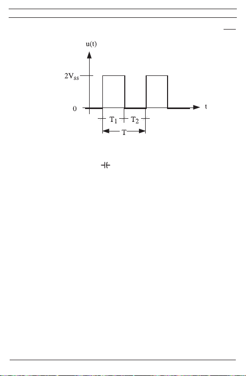
Tip:
Funktionen “%” beskriver impulsforholdet for periodiske signaler:.[%] =
T
5.1.6 Områdetasten “RANGE” 6 tjener til videreskift af det manuelle måleområde med samtidig udblænding af “AUTO” i displayet. Ved længere tastetryk
(1 sekund) vælges automatisk områdevalg (visning “AUTO”).
I drejeomskifterstillingen har tasten “RANGE” en relativværdi-funktion
“REL ∆”. Ved tasteaktivering lagres den aktuelle måleværdi, og differensen
(Offset) mellem den lagrede måleværdi og den følgende måleværdi vises.
Relativværdi-funktionen “REL ∆” muliggør nulstilling i kapacitansområdet
med måleledninger, der ikke har været i berøring. En ny tasteaktivering
skifter tilbage til normalmodus.
5.1.7 Målehastigheden for BENNING MM P3 udgør nominelt 3 målinger pr. sekund for digitaldisplayet.
5.1.8 BENNING MM P3 tændes eller slukkes via drejeomskifteren 7. Slukket stilling “OFF”.
5.1.9 BENNING MM P3 slukker selv efter ca. 30 min (APO, Auto-Power-Off). Den
automatiske afbrydelse kan deaktiveres, idet tasten “RANGE” aktiveres og
BENNING MM P3 samtidigt tændes fra omskifterstillingen “OFF”.
5.1.10
Måleværdiens temperaturkoefficient: 0,2 x (angivet målenøjagtighed)/ °C < 18 °C
eller > 28 °C, baseret på værdien ved referencetemperaturen på 23 °C.
5.1.11 BENNING MM P3 strømforsynes fra to 1,5 V batterier (LR44).
5.1.12 Hvis batterispændingen synker under den af BENNING MM P3 tilvejebragte
arbejdsspænding, fremkommer et batterisymbol i displayet .
5.1.13 Batteriernes levetid udgør ca 100 timer (alkalibatteri).
5.1.14 Apparatmål: (L x B x H) = 132 x 86 x 19 mm med beskyttelsesetui
Apparatvægt: 130 g med beskyttelsesetui og batteri.
5.1.15 Sikkerhedsmåleledningerne er udført i 2 mm-stik-teknik. De tilsluttede sikkerhedsmåleledninger lever op til BENNING MM P3’s mærkespænding.
6. Omgivelsesbetingelser
- BENNING MM P3 er beregnet til målinger i tørre omgivelser,
- Barometerhøjde ved målinger: max. 2000 m,
61
03/ 2014
BENNING MM P3
T1

- Overspændningskategori/installationskategori: IEC 60664-1/ IEC 61010-1 →
300 V kategori III; 600 V kategori II,
- Tilsmudsningsgrad: 2,
- Beskyttelsesklasse: IP 30 DIN VDE 0470-1 IEC/EN 60529
Beskyttelse mod adgang til farlige dele ogbeskyttelse mod faste fremmedle-
gemer > 2,5 mm i diameter, (3 - første kodeciffer).
Ingen vandbeskyttelse, (0 - andet kodeciffer).
- Arbejdstemperatur og relativ luftfugtighed:
Ved arbejdstemperatur fra 0 °C til 30 °C: relativ luftfugtighed mindre end 80 %,
Ved arbejdstemperatur fra 31 °C til 40 °C: relativ luftfugtighed mindre end 75 %,
Ved arbejdstemperatur fra 41 °C til 50 °C: relativ luftfugtighed mindre end 45 %,
- Opbevaringstemperatur: BENNING MM P3 kan opbevares ved temperaturer fra
- 20 °C til + 60 °C (luftfugtighed 0 til 80 %). Samtidigt skal batteriet udtages af
apparatet.
7. Elektriske oplysninger
Bemærkning: Målenøjagtigheden er angivet som sum af
- en relativ andel af måleværdien og
- et antal cifferskridt (dvs. talskridt på sidste ciffer).
Denne målenøjagtighed gælder ved temperaturer fra 18 °C til 28 °C og en relativ
luftfugtighed mindre end 80%.
7.1 Jævnspændingsområder (omskifterstilling: VDC, mVDC)
Indgangsmodstanden udgør 10 MΩ.
Måleområde Opløsning Målenøjagtighed
400 mV 0,1 mV ± (0,7 % af måleværdien + 5 Cifferskridt)
4 V 1 mV ± (0,6 % af måleværdien + 2 Cifferskridt)
40 V 10 mV ± (0,6 % af måleværdien + 2 Cifferskridt)
400 V 100 mV ± (0,6 % af måleværdien + 2 Cifferskridt)
600 V 1 V ± (0,7 % af måleværdien + 5 Cifferskridt)
7.2 Vekselspændingsområder (omskifterstilling: VAC, Hz, %)
Indgangsmodstanden udgør 10 MΩ parallel med 100 pF.
Måleområde Opløsning
Målenøjagtighed *1
i frekvensområdet 50 Hz - 500 Hz
400 mV 0,1 mV ± (1,5 % af måleværdien + 5 Cifferskridt)
4 V 1 mV ± (0,9 % af måleværdien + 5 Cifferskridt)
40 V 10 mV ± (0,9 % af måleværdien + 5 Cifferskridt)
400 V 100 mV ± (0,9 % af måleværdien + 5 Cifferskridt)
600 V 1 V ± (0,9 % af måleværdien + 5 Cifferskridt)
62
03/ 2014
BENNING MM P3
Overbelasnings-
beskyttelse
600 V
DC
600 V
DC
600 V
DC
600 V
DC
600 V
DC
Overbelasnings-
beskyttelse
600 V
eff
600 V
eff
600 V
eff
600 V
eff
600 V
eff
Måleværdien fra BENNING MM P3 fremkommer ved middelværdiensretning og vises
som effektivværdi.
*1
Målenøjagtigheden er specificeret for en sinuskurveform. Ved ikke-sinusformede
kurveformer bliver visningsværdien unøjagtigere.
7.3 Modstandsområder (omskifterstilling: Ω, , )
Overbelastningsbeskyttelse ved modstandsmålinger: 600 V
Måleområde Opløsning Målenøjagtighed
400 Ω 0,1 Ω ± (0,9 % af måleværdien + 5 Cifferskridt) 0,4 V
4 kΩ 1 Ω ± (0,9 % af måleværdien + 2 Cifferskridt) 0,4 V
40 kΩ 10 Ω ± (0,9 % af måleværdien + 2 Cifferskridt) 0,4 V
400 kΩ 100 Ω ± (0,9 % af måleværdien + 2 Cifferskridt) 0,4 V
4 MΩ 1 kΩ ± (1,5 % af måleværdien + 5 Cifferskridt) 0,4 V
40 MΩ 10 kΩ ± (1,5 % af måleværdien + 5 Cifferskridt) 0,4 V
7.4 Diode- og gennemgangstest (omskifterstilling:
Overbelastningsbeskyttelse: 600 V
Den indbyggede brummer lyder ved en modstand R mindre end 50 Ω.
eff
Måleområde Opløsning Max. målestrøm Max. tomgangssp.
1 mV 1,1 mA 1,5 V
7.5 Kapacitansområder (omskifterstilling: )
Betingelser: Kondensatorer aades og påtrykkes den angivne polaritet.
Overbelastningsbeskyttelse ved kapacitansmålinger: 600 V
Måleområde Opløsning Målenøjagtighed
50 nF 10 pF ± (5,0 % af måleværdien + 0,2 nF)*
500 nF 100 pF ± (2,9 % af måleværdien + 5 Cifferskridt)
5 µF 1 nF ± (2,9 % af måleværdien + 5 Cifferskridt)
50 µF 10 nF ± (2,9 % af måleværdien + 5 Cifferskridt)
100 µF 100 nF ± (2,9 % af måleværdien + 5 Cifferskridt)
Måletiden er afhængig af kondensatorstørrelsen og kan løbe op til 20 sekunder.
* Målenøjagtigheden er specificeret for måleværdier fra 10 nF og foregående nul-
stilling via tasten “RANGE/ REL Δ ( )” 6.
7.6 Frekvensområder
Overbelastningssikring ved frekvensmålinger: 600 V
7.6.1 Frekvensområder for rkantsignaler (omskifterstilling: Hz, %)
Ω,
eff
eff
, )
eff
Max. tomgangsspænding
63
03/ 2014
BENNING MM P3

Måleområde Opløsning
5 Hz 0,001 Hz ± (0,3 % af måleværdien + 5 Cifferskridt) > 1,0 Vss (Firkant)
50 Hz 0,01 Hz ± (0,3 % af måleværdien + 5 Cifferskridt) > 1,0 Vss (Firkant)
500 Hz 0,1 Hz ± (0,3 % af måleværdien + 5 Cifferskridt) > 1,0 Vss (Firkant)
5 kHz 1 Hz ± (0,3 % af måleværdien + 5 Cifferskridt) > 1,0 Vss (Firkant)
50 kHz 10 Hz ± (0,3 % af måleværdien + 5 Cifferskridt) > 1,0 Vss (Firkant)
500 kHz 100 Hz ± (0,3 % af måleværdien + 5 Cifferskridt) > 1,0 Vss (Firkant)
5 MHz 1 kHz ± (0,3 % af måleværdien + 5 Cifferskridt) > 1,0 Vss (Firkant)
7.6.2 Frekvensvisning for sinussignaler (omskifterstilling: VAC, Hz, %) og aktivering
af “SELECT”-tasten:
Målenøjagtighed: ± (0,3 % + 5 cifferskridt) gyldig for sinusspændinger op til
600 V
(10 Hz - 500 Hz) og udlæste værdier i vekselstrømsområdet (VAC)
eff
større end 50 % af måleområdets max-værdi.
7.7 Impulsforholdforrkantsignaler (omskifterstilling: Hz, %)
Overbelastningssikring ved impulsforhold: 600 V
Måleområde Opløsning
0,1 % - 99,9 % 0,1 % ± (0,5 % af måleværdien + 3 Cifferskridt) > 1,0 Vss (Firkant)
8. Måling med BENNING MM P3
8.1 Forberedelse af måling
BENNING MM P3 må kun benyttes og opbevares ved de angivne opbevarings- og
arbejdstemperaturbetingelser; undgå vedvarende solindstråling.
- Den tilsluttede sorte og røde sikkerhedsmåleledning opfylder den gældende fors-
krift, når de er ubeskadiget.
- Den tilsluttede sorte og røde sikkerhedsledning skal beskyttes mod urenheder.
- Sikerhedsmåleledningernes isolering kontrolleres. Hvis isoleringen er beska-
diget, skal apparatet straks tages ud af brug.
- Sikkerhedsmåleledninger skal testes for gennemgang. Hvis lederen i sikkerheds-
måleledningen er brudt, skal apparatet straks tages ud af brug.
- Før en anden funktion vælges på drejeomskifteren 7, skal sikkerhedsmåleled-
ningerne fjernes fra målepunktet.
- Stærke støjkilder i nærheden af BENNING MM P3 kan føre til ustabil visning og
til målefejl.
8.2 Spændingsmåling
Max. spænding mod jordpotential skal overholdes!
Elektrisk risiko!
Målenøjagtighed for 5 Vss max
(firkantsignal)
Målenøjagtighed indtil 5 Vss max
eff
(firkantsignal, 5 Hz - 5 kHz)
Følsomhed
Følsomhed
(30% ≤ % ≤ 70%)
64
03/ 2014
BENNING MM P3

Den største spænding, der må ligge på ledninger
- COM- tilslutning
- tilslutning (rød) for V, Ω, , Hz
i BENNING MM P3 i forhold til jord, udgør 600 V.
- Med drejeomskifteren 7 vælges den ønskede funktion (V AC) eller (V DC) på
BENNING MM P3.
- Sikkerhedsmåleledningerne bringes i kontakt med målepunkterne, måleværdien
aflæses på digitaldisplayet på BENNING MM P3.
- I drejeomskifterstilling (VAC) kan tasten “SELECT” 5 bruges til at foretage skift til
frekvensmåling (tast trykkes én gang) eller impulsforholdsmåling (tast trykkes to
gange).
Tip:
I lave spændingsområder og med åbne sikkerhedmålesledninger kan 0 V-visningen
udeblive på grund af indstråling. BENNING MM P3 funktionstestes ved kortslutning
af målespidserne.
se gur 2: Jævnspændingsmåling
se gur 3: Vekselspændingsmåling
8.3 Modstandsmåling
- Med drejeomskifteren 7 vælges den ønskede funktion (Ω, , ) på
BENNING MM P3.
- Sikkerhedsmåleledningerne bringes i kontakt med målepunkterne, måleværdien
aflæses på digitaldisplayet på BENNING MM P3.
se gur 4: Modstandsmåling
8.4 Diodetest
- Med drejeomskifteren 7 vælges den ønskede funktion (Ω, , ) på
BENNING MM P3.
- Med tasten “SELECT” 5 på BENNING MM P3 foretages skift til diodetest ( )
(tasten trykkes én gang).
- Sikkerhedsmåleledningerne bringes i kontakt med diodetilledningerne, målevær-
dien aflæses på digitaldisplayet på BENNING MM P3.
- For en normal Si-diode, påtrykt i lederetningen, vises gennemgangsspændingen
mellem 0,400 V og 0,900 V. Visningen “000” henviser til en kortslutning i dioden,
visningen “000” henviser til et brud i dioden.
- For en diode, påtrykt i spærreretningen, vises “OL”. Hvis dioden er fejlbehæftet,
vises “000” eller andre værdier.
se gur 5: Diodetest
8.5 Gennemgangstest med brummer
- Med drejeomskifteren 7 vælges den ønskede funktion (Ω, , ) på
BENNING MM P3.
- Med tasten “SELECT” 5 på BENNING MM P3 foretages skift til gennem-
gangstest ( ) tasten trykkes to gange).
- Sikkerhedsmåleledningerne bringes i kontakt med målepunkterne.
- Hvis modstanden mellem målepunkterne underskrider 50 Ω, lyder den ind-
65
03/ 2014
9
BENNING MM P3
8

byggede brummer i BENNING MM P3.
se gur 6: Gennemgangstest med brummer
8.6 Kapacitansmåling
Kondensatoreraadesfuldstændigtførkapacitansmålinger!Bøsningerne for kapacitansmåling må aldrig påtrykkes spænding! Ap-
paratet kan blive beskadiget eller ødelagt! Et beskadiget appaprat
kan udgøre en elektrisk risiko!
- Med drejeomskifteren 7 vælges den ønskede funktion ( ) på
BENNING MM P3.
- Kondensatorens polaritet fastslås, og kondensatoren aflades fuldstændigt.
- I givet fald udføres nulstilling via tasten “RANGE/ REL Δ ( ) ” 6.
- Sikkerhedsmåleledningerne bringes i kontakt med den afladede kondensator i
overensstemmelse med dens polaritet, måleværdien aflæses på digitaldisplayet
på BENNING MM P3.
se gur 7: Kapacitansmåling
8.7 Frekvensmåling
- For at måle firkantsignaler op til max 5 Vss vælges den ønskede funktion (Hz, %)
med drejeomskifteren 7.
- For at måle sinussignaler op til 600 V
med drejeomskifteren 7, og skift til frekvensmåling (Hz) foretages med tasten
“SELECT”.
- Vær opmærksom på den minimale følsomhed for frekvensmålinger på
BENNING MM P3!
- Sikkerhedsmåleledningerne bringes i kontakt med målepunkterne, måleværdien
aflæses på digitaldisplayet på BENNING MM P3.
se gur 8: Frekvens-/ impulsforholdsmåling
8.8 Impulsforholdsmåling
- Med drejeomskifteren 7 vælges den ønskede funktion (Hz, %) på
BENNING MM P3.
- Med tasten “SELECT” 5 foretages skift til impulsforholdsmåling (%) på
BENNING MM P3 (tasten trykkes én gang).
- Sikkerhedsmåleledningerne bringes i kontakt med målepunkterne, måleværdien
aflæses på digitaldisplayet på BENNING MM P3.
se gur 8: Frekvens-/impulsforholdsmåling
9. Vedligeholdelse
Før åbning skal BENNING MM P3 ubetinget gøres spændingsfrit!
Elektrisk risiko!
Arbejdet på det åbnede BENNING MM P3 under spænding er udelukkende forbeholdt fagfolk, der samtidigt skal træffe foranstaltninger til ulykkesforebyggelse.
66
03/ 2014
vælges den ønskede funktion (VAC, Hz, %)
eff
BENNING MM P3

Sådan gøres BENNING MM P3 spændingsfrit, før apparatet åbnes:
- Først fjernes begge sikkerhedsmåleledninger fra måleobjektet.
- Drejeomskifteren 7 drejes til stillingen “OFF”.
9.1 Sikring af apparatet
Under bestemte forudsætninger kan sikkerheden ved omgang med BENNING MM
P3 ikke længere garanteres, f.eks. ved:
- Synlige skader på huset og på sikkerhedsmåleledningerne,
- Fejl ved målinger,
- Registrérbare følger af længere opbevaring under ikke-tilladte betingelser, og
- Registrérbare følger af ekstraordinær transportpåvirkning.
I disse tilfælde skal BENNING MM P3 øjeblikkeligt afbrydes, fjernes fra målepunkterne og sikres mod ny benyttelse.
9.2 Rengøring
Huset renses udvendigt med en ren og tør klud (undtagelse specielle renseservietter). Anvend ingen opløsnings og/eller skuremidler for at rense apparatet. Vær
ubetinget opmærksom på, at batterikassen og batterikontakterne ikke forurenes af
udsivende batteri-elektrolyt.
Såfremt elektrolyt-forureninger eller hvide aejringer er til stede i området omkring
batteriet eller batterihuset, renses også disse med en tør klud.
9.3 Batteriskift
Før åbning skal BENNING MM P3 ubetinget gøres spændingsfrit!
Elektrisk risiko!
BENNING MM P3 strømforsynes fra to indbyggede 1,5 V batterier (LR44). Et bat-
teriskift (se gur 9) er nødvendigt, hvis batterisymbolet fremkommer i displayet .
Sådan skiftes batteriet:
- Sikkerhedsmåleledningerne fjernes fra målekredsen.
- Drejeomskifteren 7 drejes til stillingen “OFF”.
- BENNING MM P3 lægges med forsiden nedad, og skruen i husets bund løsnes.
- Husets bund løftes forsigtigt af.
Ingen skruer i det trykte kredsløb i BENNING MM P3 må løsnes!
- De afladede batterier tages ud af batterikassen.
- De nye batterier lægges med polerne korrekt placeret i batterikassen, pluspolen
peger opad.
- Husets bund klikkes på overdelen, og skruerne strammes igen.
se gur 9: Batteriskift
Bidrag til bevarelse af miljøet! Batterier hører ikke hjemme i hus-
holdningsaffaldet.Dekanaeverespåetindsamlingsstedforgamle
batterier og farligt affald. Information fås hos kommunen.
67
03/ 2014
BENNING MM P3

9.4 Kalibrering
For at opretholde måleresultaternes angivne nøjagtighed skal apparatet regelmæssigt kalibreres hos vor fabriksservice. Vi anbefaler et kalibreringsinterval på ét år.
Apparatet sendes til følge adresse:
Benning Elektrotechnik & Elektronik GmbH & Co. KG
Service Center
Robert-Bosch-Str. 20
D - 46397 Bocholt
10. Anvendelse af beskyttelsesetuiet
- Sikkerhedsmåleledningerne kan opbevares, idet de vikles op og fastgøres i beskyt-
telsesetuiet med velcro-lukningen.
se gur 10: Anvendelse af beskyttelsesetuiet
11. Miljøbeskyttelse
Ved afslutningen af apparatets levetid aeveres det til et af de til rådighed
stående retur- og opsamlingssystemer.
68
03/ 2014
BENNING MM P3

Εγχειρίδιοχρήσηςγιατο
BENNING MM P3
Ψηφιακό πολύμετρο για
- μέτρηση συνεχούς τάσης
- μέτρηση εναλλασσόμενης τάσης
- μέτρηση αντίστασης
- έλεγχο διόδου
- έλεγχο συνέχειας
- μέτρηση χωρητικότητας
- μέτρηση συχνότητας
- μέτρηση παλμών λόγου
Περιεχόμενα:
1. Οδηγίεςχρήσης
2. Οδηγίεςασφάλειας
3. Λίστααντικειμένωνπουπεριέχονταιστηνσυσκευασία
4. Περιγραφήτουοργάνου
5. Γενικάδεδομένα
6. Συνθήκεςπεριβάλλοντος
7. Ηλεκτρικάδεδομένα
8. ΜετρώνταςμετοBENNINGMMP3
9. Συντήρηση
10. Χρησιμοποίησητηςπροστατευτικήςθήκης
11. Προστασίαπεριβάλλοντος
1. ΟδηγίεςΧρήσης
Το εγχειρίδιο λειτουργίας απευθύνεται σε:
- ηλεκτρολόγους και
- πρόσωπα που έχουν γνώσεις στην τεχνολογία της ηλεκτρολογίας
Το BENNING MM P3 σχεδιάστηκε για μετρήσεις σε στεγνό περιβάλλον. Δεν πρέπει
να χρησιμοποιείται σε ηλεκτρικά κυκλώματα με τάσεις μεγαλύτερες των 600 V για
συνεχές ρεύμα ή των για εναλλασσόμενο ρεύμα.(για περισσότερες λεπτομέρειες δείτε
κεφάλαιο 6 « συνθήκες περιβάλλοντος»).
Τα παρακάτω σχήματα παρουσιάζονται στο εγχειρίδιο χρήσης ,αλλά υπάρχουν και
πάνω στο ίδιο το BENNING MM P3.
Ηλεκτρικός κίνδυνος!
Προειδοποιεί και δείχνει οδηγίες που θα πρέπει να ακολουθηθούν με στόχο
να αποφευχθεί ο κίνδυνος στους ανθρώπους.
Ηλεκτρικός κίνδυνος!
Προειδοποιεί και δείχνει οδηγίες που θα πρέπει να ακολουθηθούν με στόχο
να αποφευχθεί ο κίνδυνος στους ανθρώπους.
69
03/ 2014
BENNING MM P3

Αυτό το σύμβολο πάνω στο BENNING MM P3 δείχνει ότι το όργανο είναι
προστατευμένο από βραχυκύκλωμα (βαθμίδα ασφαλείας ΙΙ).
Αυτό το σύμβολο εμφανίζεται όταν η μπαταρία έχει εκφορτιστεί.
Αυτό το σύμβολο δηλώνει την εφαρμογή του ‘ελέγχου διόδου’.
Αυτό το σύμβολο δηλώνει την εφαρμογή του ‘ελέγχου συνέχειας’. Ο
βομβητής παρέχει ένα ακουστικό σήμα.
Αυτό το σύμβολο δείχνει την κλίμακα της λειτουργίας ‘έλεγχος
χωρητικότητας’.
DC ρεύμα
AC ρεύμα
Γείωση
2. Υπόδειξηασφαλείας
Το όργανο έχει ελεγχθεί σύμφωνα με το
DIN VDE 0411 μέρος 1/ ΕΝ 61010-1
κι έχει φύγει από το εργοστάσιο σε πλήρως ασφαλή τεχνική κατάσταση.
Για να διατηρηθεί η κατάσταση αυτή και να διασφαλισθεί η ασφαλής λειτουργία της
συσκευής ελέγχου, ο χρήστης πρέπει κάθε φορά να παρατηρεί τις σημειώσεις και τις
προειδοποιήσεις που δίνονται σε αυτό το εγχειρίδιο οδηγιών.
Το όργανοθα πρέπει να χρησιμοποιείται μόνο σε ηλεκτρικά
κυκλώματαεντός της κατηγορίας ΙΙ για υπέρταση,με έναν αγωγό
για600VmaxωςπροςγηήεντόςτηςκατηγορίαςIΙΙγιαυπέρταση
μεέναναγωγόγια300Vωςπροςγη.
Θυμηθείτε ότι κάθε εργασία πάνω σε ηλεκτρικά εξαρτήματα κάθε
είδους είναι επικίνδυνη. Ακόμα και χαμηλές τάσεις των 30V AC
και των 60V CD μπορούν να αποδειχθούν επικίνδυνες για την
ανθρώπινηζωή.
Ανπαρατηρηθεί ότι η ασφαλής λειτουργία της συσκευής ελέγχου
δενείναιπλέονεφικτή,τότεθαπρέπειναδιακόπτεταιηλειτουργία
αμέσως και να ασφαλίζεται η συσκευή, ώστε να αποφεύγεται η
πιθανότητανατεθείσελειτουργίακατάλάθος.
Μπορεί να υποτεθεί ότι δεν υπάρχει πλέον ασφαλής λειτουργία :
- αν το όργανο ή τα καλώδια μετρήματος δείχνουν σημάδια φθοράς, ή
- αν η συσκευή ελέγχου δεν λειτουργεί πλέον, ή
- μετά από μακρές περιόδους φύλαξης κάτω από δυσμενείς συνθήκες, ή
70
03/ 2014
BENNING MM P3

- μετά από έκθεση σε βίαιη μεταφορά.
Γιανααποφύγετετονκίνδυνο,
- μην ακουμπάτε σε απολήξεις των καλωδίων με φθαρμένη
3. Λίστααντικειμένωνπουπεριέχονταιστηνσυσκευασία
Το πακέτο του BENNING MM P3 αποτελείται από τα παρακάτω μέρη:
Οδηγίες για τα αναλώσιμα εξαρτήματα:
- Το BENNING MM P3 τροφοδοτείται από δύο μπαταρίες 1,5 V (LR 44).
4. Περιγραφήτουοργάνου
Βλέπε σχήμα 1: Μπροστινή όψη
Η οθόνη και τα στοιχεία λειτουργίας που φαίνονται στο σχήμα 1 είναι τα ακόλουθα:
ψηφιακή οθόνη, για διάβασμα των μετρήσεων και απεικόνιση των εκτός
απεικόνισητηςπολικότητας,
απεικόνισητηςμπαταρίας, φαίνεται όταν η μπαταρία έχει εκφορτιστεί
4
HOLDπλήκτρο, αποθηκεύει στη μνήμη την μέτρηση
5
ΠλήκτροSELECT,για επιλογή της δεύτερης και τρίτης λειτουργίας,
6
RANGEπλήκτροκλίμακας, περιστρέφει ανάμεσα σε αυτόματη και χειροκίνητη
7
Περιστρεφόμενοςδιακόπτης, για επιλογή της λειτουργίας μέτρησης.
8
9
COM-Ασφαλιστικόςαγωγόςμέτρησης(μαύρος),κοινή σύνδεση για μετρήσεις
1) Η πολικότητα απεικονίζεται αυτόματα για DC τάσεις που αναφέρονται σε αυτές
5. Γενικάστοιχεία
5.1 Γενικάδεδομέναπάνωστοπολύμετρο
5.1.1 Η ψηφιακή οθόνη είναι σχεδιασμένη σαν 35/6½-ψήφιος ενδείκτης υγρού
5.1.2 Ο δείκτης πολικότητας λειτουργεί αυτόματα. Ενδείκνυται μόνο ένα
5.1.3 Όταν έχουμε υπερφόρτιση αυτό απεικονίζεται με την ένδειξη ‘OL’ ή ‘-OL’ και
Προσοχή: δεν υπάρχει κάποια ένδειξη ή προειδοποίηση κατά την πλήρη
71
03/ 2014
επένδυση
3.1 Ένα BENNING MM P3 με δυο σταθερά συνδεδεμένους ασφαλιστικούς
αγωγούς μέτρησης, μαύρο και κόκκινο (L = 0,6 m; άκρη Ø = 2 mm),
3.2 ´Eνα τεμάχιο προστατευτικής θήκη
3.3 Δύο μπαταρίες 1,5 V (LR 44)(ενσωματωμένες στην μονάδα)
3.4 Ένα εγχειρίδιο λειτουργίας
κλίμακας ενδείξεων.
κλίμακα μέτρησης.
Ασφαλιστικόςαγωγόςμέτρησης(κόκκινος),θετική1 σύνδεση για V, Ω, , Hz,
τάσης, αντίστασης, συχνότητας, παλμών λόγου, χωρητικότητα, συνέχεια και
έλεγχο διόδων
κρυστάλλου με ύψος ψηφίου 14 mm και δεκαδικό μέρος. Η μεγαλύτερη τιμή
που μπορεί να απεικονιστεί είναι 5000.
ηλεκτρόδιο σε αντίθεση με τον ορισμό κάλυκα με „-“.
καμιά φορά με ακουστικό σήμα.
BENNING MM P3
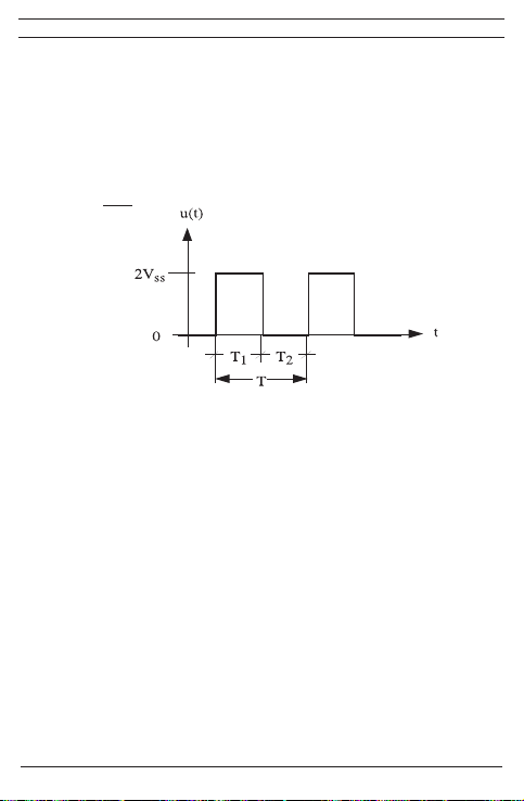
υπερφόρτιση.
5.1.4 HOLD-αποθηκεύει την τιμή που διαβάζουμε: Όταν πιέσουμε το πλήκτρο
“HOLD” 4, η μέτρηση που εκείνη την στιγμή διαβάζει το μηχάνημα
αποθηκεύεται στη μνήμη. Συγχρόνως εμφανίζεται στην οθόνη η ένδειξη
“HOLD” . Αν πατήσουμε για δεύτερη φορά το πλήκτρο “HOLD”, η συσκευή
επιστρέφει στην λειτουργία μέτρησης.
5.1.5 Το πλήκτρο „SELECT” 5 επιλέγει τη δεύτερη και τρίτη λειτουργίας της θέσης
περιστροφικού διακόπτη.
Υπόδειξη:
Η λειτουργία „%” περιγράφει τον συντελεστή παλμών περιοδικών σημάτων:
[%] =
5.1.6 Το πλήκτρο κλίμακας RANGE 6 είναι για να μεγαλώνει χειροκίνητα την
Στη θέση περιστροφικού διακόπτη (σύμβολο χωρητικότητας) έχει το πλήκτρο
5.1.7 Ο ονομαστικός ρυθμός μέτρησης του BENNING MM P3 είναι 3 μετρήσεις το
5.1.8 Το BENNING MM P3 μπαίνει εντός και εκτός λειτουργίας περιστρέφοντας το
5.1.9 Το BENNING MM P3 βγαίνει αυτόματα εκτός λειτουργίας μετά από περίπου
5.1.10 Ο συντελεστής θερμοκρασίας για τις τιμές των μετρήσεων: 0,2 x
5.1.11 Το BENNING MM P3 τροφοδοτείται από δύο μπαταρίες 1,5 V (LR 44).
72
03/ 2014
T1
T
ακτίνα μέτρησης, ενώ συγχρόνως αχνοσβήνεται στην οθόνη η ένδειξη
‘AUTO’.Όταν το πλήκτρο πατηθεί παρατεταμένα (1 δεύτερπ), επιλέγεται
αυτόματα η επιλογή κλίμακας (ένδειξη ‘AUTO’).
„RANGE“ μια λειτουργία σχετικής τιμής „REL ∆“. Με την ενεργοποίηση
πλήκτρου αποθηκεύεται η υπάρχουσα τιμή μέτρησης και ενδεικνύεται
η διαφορά (Offset) μεταξύ της αποθηκευμένης τιμής μέτρησης και των
επακόλουθων τιμών μέτρησης. Η λειτουργία σχετικής τιμής „REL ∆“ δίνει
τη δυνατότητα για το μηδενικό συντονισμό του τομέα χωρητικότητας σε
αγωγούς μέτρησης μη έχοντες επαφή. Μια εκ νέου ενεργοποίηση του
πλήκτρου επαναφέρει στον κανονικό τρόπο λειτουργίας.
δευτερόλεπτο, για την ψηφιακή απεικόνιση.
διακόπτη 7. Εκτός λειτουργίας είναι η θέση “OFF”.
30 λεπτά αναμονής (APO, Auto-Power-Off). Η αυτόματη διακοπή λειτουργίας
απενεργοποιείται αν πατηθεί το πλή κτρο “RANGE” και ταυτόχρονα βάζουμε
το BENNING MM P3 από τη θέση “OFF” σε λειτουργία.
(καθορισμένη ακρίβεια μέτρησης)/ °C < 18 °C ή > 28 °C σχετική με την τιμή
στην θερμοκρασία αναφοράς των 23 °.
BENNING MM P3

5.1.12 Όταν η τάση της μπαταρίας πέφτει κάτω από μια συγκεκριμένη τάση
λειτουργίας για το BENNING MM P3, εμφανίζεται στην οθόνη η ένδειξη
μπαταρίας .
5.1.13 Η διάρκεια ζωής μιας μπαταρίας είναι περίπου 100 ώρες (αλκαλικκες
μπαταρίες)
5.1.14 Διαστάσεις οργάνου: (Μ x Π x Υ) = 132 x 86 x 19 mm με θήκη
Βάρος οργάνου: 130 gr με θήκη και μπαταρία
5.1.15 Τα καλώδια μέτρησης ασφαλείας είναι 2 mm τύπου βύσματος και κατάλληλα
για την τάση και την ισχύ εντός κλίμακας του BENNING MM P3.
6. Συνθήκεςπεριβάλλοντος
-
Το BENNING MM P3 είναι σχεδιασμένο μόνο για μετρήσεις σε στεγνό περιβάλλον.
- Μέγιστο βαρομετρικό ύψος κατά την διάρκεια της μέτρησης : 2000m
- Κατηγορία υπερφόρτισης / κατηγορία set-up : IEC 60664-1/ IEC 61010-1
→ 300 V κατηγορία ΙΙΙ; 600 V κατηγορία ΙΙ
- Βαθμός μόλυνσης : 2
- Σύστημα προστασίας : IP 30 DIN VDE 0470-1 IEC/ EN 60529).
Το IP 30 σημαίνει: Προστασία από πρόσβαση σε επικίνδυνα μέρη και προστασία
από στερεές προσμίξεις διαμέτρου > 2,5 mm, (3 - πρώτο ψηφίο). Καμία
προστασία στο νερό, (0 - δεύτερο ψηφίο).
- Θερμοκρασία λειτουργίας και σχετιζόμενη υγρασία :
Σε θερμοκρασία λειτουργίας 0 °C μέχρι 30 °C : σχετιζόμενη υγρασία μικρότερη
του 80 %.
Σε θερμοκρασία λειτουργίας 31 °C μέχρι 40 °C : σχετιζόμενη υγρασία κάτω από
75 %.
Σε θερμοκρασία λειτουργίας 41 °C μέχρι 50 °C : σχετιζόμενη υγρασία κάτω από
45 %.
- Θερμοκρασία αποθήκευσης : Το BENNING MM P3 μπορεί να αποθηκευτεί σε
θερμοκρασίες από - 20 °C μέχρι + 60 °C (υγρασία 0 μέχρι 80 %). Οι μπαταρίες
πρέπει να έχουν αφαιρεθεί από την συσκευή.
7. Ηλεκτρικάδεδομένα
Σημείωση : Η ακρίβεια της μέτρησης δηλώνεται ως το σύνολο
- μιας σχετικής αναλογίας της τιμής της μέτρησης και
- ένα αριθμό ψηφίων (αριθμητικά βήματα από τη τελευταία μέτρηση ).
Αυτή η ακρίβεια μέτρησης δηλώνεται για θερμοκρασίες από 18 °C μέχρι 28 °C και
αντίστοιχη μέγιστη υγρασία 80 %.
7.1 Κλίμακαμέτρησηςσυνεχούςτάσης(Θέση διακοπτών: VDC, mVDC)
Η αντίσταση εισόδου είναι 10 ΜΩ.
Κλίμακα
μέτρησης
Ανάλυση Ακρίβεια μέτρησης
400 mV 0,1 mV ± (0,7 % από αυτό που διαβάζουμε + 5
4 V 1 mV ± (0,6 % από αυτό που διαβάζουμε + 2
40 V 10 mV ± (0,6 % από αυτό που διαβάζουμε + 2
73
03/ 2014
BENNING MM P3
Προστασία
υπερφόρτισης
ψηφία)600 V
ψηφία)600 V
ψηφία)600 V
DC
DC
DC

400 V 100 mV ± (0,6 % από αυτό που διαβάζουμε + 2
600 V 1 V ± (0,7 % από αυτό που διαβάζουμε + 5
7.2 Κλίμακαμέτρησηςεναλλασσόμενηςτάσης (Θέση διακοπτών: VAC, Hz, %)
Η αντίσταση εισόδου είναι 10 ΜΩ παράλληλη σε 100 pF.
Κλίμακα
μέτρησης
Ανάλυση
Ακρίβεια μέτρησης *1 στην
ακτίνα συχνότητας 50 Ηz - 500 Ηz
400 mV 0,1 mV ± (1,5 % από αυτό που διαβάζουμε + 5
4 V 1 mV ± (0,9 % από αυτό που διαβάζουμε + 5
40 V 10 mV ± (0,9 % από αυτό που διαβάζουμε + 5
400 V 100 mV ± (0,9 % από αυτό που διαβάζουμε + 5
600 V 1 V ± (0,9 % από αυτό που διαβάζουμε + 5
Η τιμή μέτρησης του BENNING MM P3 υπολογίζεται από μέση τιμή ανόρθωσης και
αποτυπώνεται ως πραγματική τιμή.
*1 Η ακρίβεια μέτρησης είναι προσαρμοσμένη σε τύπο ημιτονικής μορφής καμπύλη.
Σε μη-ημιτονοειδή καμπύλες , η τιμή που απεικονίζεται είναι λιγότερο ακριβής.
7.3 Κλίμακεςαντίστασης(Θέση διακοπτών: (Ω, , )
Προστασία υπερφόρτισης για αντίσταση : 600 V
Κλίμακα
μέτρησης
Ανάλυση Ακρίβεια μέτρησης
eff
400 Ω 0,1 Ω ± (0,9 % από αυτό που διαβάζουμε + 5
4 kΩ 1 Ω ± (0,9 % από αυτό που διαβάζουμε + 2
40 kΩ 10 Ω ± (0,9 % από αυτό που διαβάζουμε + 2
400 kΩ 100 Ω ± (0,9 % από αυτό που διαβάζουμε + 2
4 MΩ 1 kΩ ± (1,5 % από αυτό που διαβάζουμε + 5
40 MΩ 10 kΩ ± (1,5 % από αυτό που διαβάζουμε + 5
7.4 Έλεγχοςδιόδωνκαισυνέχειας(Θέση διακοπτών: (Ω, , )
Προστασία υπερφόρτισης : 600 V
Ο ενσωματωμένος βομβητής ηχεί σε αντίσταση R < 50 Ω.
Κλίμακα μέτρησης Ανάλυση
.
eff
Μέγιστο ρεύμα
μέτρησης
1 mV 1,1 mA 1,5 V
.
ψηφία)600 V
ψηφία)600 V
Προστασία
υπερφόρτισης
ψηφία)600 V
ψηφία)600 V
ψηφία)600 V
ψηφία)600 V
ψηφία)600 V
Μέγιστη τάση χωρίς
φορτίο
ψηφία
) 0,4 V
ψηφία
) 0,4 V
ψηφία
) 0,4 V
ψηφία
) 0,4 V
ψηφία
) 0,4 V
ψηφία
) 0,4 V
Μέγιστη τάση χωρίς φορτίο
DC
DC
eff
eff
eff
eff
eff
7.5 Κλίμακεςχωρητικότητας (Θέση διακοπτών: ( )
Συνθήκες: οι πυκνωτές εκφορτίζονται και συνδέονται σε σχέση με την καθορισμένη
74
03/ 2014
BENNING MM P3

Προστασία υπερφόρτισης για μετρήσεις χωρητικότητας: 600 V
Κλίμακα μέτρησης Ανάλυση Ακρίβεια μέτρησης
Η διάρκεια μέτρησης εξαρτάται από το μέγεθος του συμπυκνωτή και δύναται να
ανέρχεται έως και 20 δευτερόλεπτα.
* Η ακρίβεια μέτρησης είναι προσδιορισμένη για τιμές μέτρησης από 10 nF και
7.6Κλίμακεςσυχνότητας
Προστασία υπερφόρτισης για μετρήσεις συχνότητας: 600 V
7.6.1 Τομείς συχνότητας για τετραγωνικά σήματα (θέση διακόπτη: Hz, %)
7.6.2 Ένδειξη συχνότητας για ημιτονοειδή σήματα (θέση διακόπτη: VAC, Hz, %) και
Ακρίβεια μέτρησης: ± (0,3 % + 5 Digit) ισχύουσα για ημιτονοειδείς τάσεις έως
7.7Συντελεστήςπαλμώνγιατετραγωνικάσήματα(θέση διακόπτη: Hz, %)
Προστασία υπερφόρτωσης σε περίπτωση ποτελέσματος μέτρησης της αναλογίας
μηχανικού παλμού : 600 V
Κλίμακα μέτρησης Ανάλυση
πολικότητα.
.
eff
50 nF 10 pF ± (5,0 % από αυτό που διαβάζουμε + 0,2 nF)*
500 nF 100 pF ± (2,9 % από αυτό που διαβάζουμε + 5
5 µF 1 nF ± (2,9 % από αυτό που διαβάζουμε + 5
50 µF 10 nF ± (2,9 % από αυτό που διαβάζουμε + 5
100 µF 100 nF ± (2,9 % από αυτό που διαβάζουμε + 5
ψηφία
ψηφία
ψηφία
ψηφία
)
)
)
)
προηγούμενο μηδενικό συντονισμό με το πλήκτρο „RANGE/ REL Δ ( )“ 6.
.
eff
Κλίμακα
μέτρησης
Ανάλυση
5 Hz 0,001 Hz ± (0,3 % από αυτό που διαβάζουμε + 5
50 Hz 0,01 Hz ± (0,3 % από αυτό που διαβάζουμε + 5
500 Hz 0,1 Hz ± (0,3 % από αυτό που διαβάζουμε + 5
5 kHz 1 Hz ± (0,3 % από αυτό που διαβάζουμε + 5
50 kHz 10 Hz ± (0,3 % από αυτό που διαβάζουμε + 5
500 kHz 100 Hz ± (0,3 % από αυτό που διαβάζουμε + 5
5 MHz 1 kHz ± (0,3 % από αυτό που διαβάζουμε + 5
Ακρίβεια μέτρησης για 5 VSS max
(τετραγωνικό σήμαα)
Ευαισθησία
ψηφίο
) > 1,0 Vss (τετράγωνο)
ψηφίο
) > 1,0 Vss (τετράγωνο)
ψηφίο
) > 1,0 Vss (τετράγωνο)
ψηφίο
) > 1,0 Vss (τετράγωνο)
ψηφίο
) > 1,0 Vss (τετράγωνο)
ψηφίο
) > 1,0 Vss (τετράγωνο)
ψηφίο
) > 1,0 Vss (τετράγωνο)
ενεργοποίηση του πλήκτρου „SELECT“:
600 V
(10 Hz - 500 Hz) και ενδεικτικές τιμές του τομέα εναλλασσόμενης
eff
τάσης (VAC) μεγαλύτερη 50 % της τελική τιμής του τομέα μέτρησης
eff
Ακρίβεια μέτρησης έως 5 VSS max.
(Τετραγωνικό σήμα, 5 Hz - 5 kHz)
Ευαισθησία
(30 % ≤ % ≤ 70 %)
0,1 % - 99,9 % 0,1 % ± (0,5 % από αυτό που διαβάζουμε + 3 ψηφίο) > 1,0 Vss (τετράγωνο)
75
03/ 2014
BENNING MM P3

8. ΜετρώνταςμετοBENNINGMMP3
8.1 Προετοιμασίαγιατηνμέτρηση
Αποθηκεύστε και χρησιμοποιήστε το BENNING MM P3 μόνο κάτω από τις σωστές
συνθήκες θερμοκρασίας που έχουν καθοριστεί. Να αποφεύγετε πάντα την μεγάλη
έκθεση στον ήλιο.
- Ο συνδεδεμένος μαύρος και κόκκινος ασφαλιστικός αγωγός μέτρησης
ανταποκρίνεται στην ισχύουσα προδιαγραφή, εάν αυτοί δεν φέρουν βλάβη.
- Ο συνδεδεμένος μαύρος και κόκκινος ασφαλιστικός αγωγός μέτρησης πρέπει να
προστατεύονται από βρωμιές.
- Ελέγξτε την μόνωση των καλωδίων μέτρησης. Αν η μόνωση είναι κατεστραμμένη,
η συσκευή να αποσυρθεί αμέσως
- Ελέγξτε την συνέχεια των καλωδίων μέτρησης. Αν ο αγωγός στα καλώδια
μέτρησης είναι διαβρωμένος, η συσκευή να αποσυρθεί αμέσως
-
Πριν επιλέξετε κάποια άλλη λειτουργία με τον διακόπτη περιστροφής 7, να
αποσυνδέετε πάντα τoυς ακροδέκτες ασφαλούς ελέγχου από το σημείο μέτρησης.
- Πηγές ισχυρού ρεύματος ,που βρίσκονται κοντά στο
BENNING MM P3,μπορούν να προκαλέσουν ασταθείς ή λανθασμένες ενδείξεις.
8.2 Μέτρησητάσης
Πάνταναπαρατηρείτετηνμέγιστητάσησεσχέσημετηγη.
Κίνδυνοςγιαηλεκτροπληξία!
Η μέγιστη τάση που μπορεί να εφαρμοστεί στις πρίζες
9
- COM
- για V, Ω, , Hz
του BENNING MM P3 και στη γή είναι 600 V.
- Με τον περιστρεφόμενο διακόπτη 7 επιλέξτε την επιθυμητή λειτουργία (V AC) ή
(V DC) στο BENNING MM P3.
- Συνδέστε τα καλώδια μέτρησης στα σημεία μέτρησης. Διαβάστε την
τιμή της μέτρησης που απεικονίζεται στην ψηφιακή οθόνη του
BENNING MM P3.
- Στη θέση περιστροφικού διακόπτη (VAC) μπορεί να πραγματοποιηθεί με το
πλήκτρο „SELECT“ 5 η μεταγωγή σε μέτρηση συχνότητας (πατήστε το πλήκτρο
μια φορά) ή σε μέτρηση παλμών λόγου (πατήστε το πλήκτρο δυο φορές) .
Υπόδειξη:
Σε μικρούς τομείς τάσης μπορεί να παραλειφθεί σε ανοικτούς ασφαλιστικούς
αγωγούς μέτρησης η ένδειξη μηδενικού βολτ. Ελέγξατε το BENNING MM P3 ως προς
λειτουργία με βραχυκύκλωμα των άκρων μέτρησης.
Βλέπε σχήμα 2: Μέτρηση συνεχούς ρεύματος
Βλέπε σχήμα 3: Μέτρηση αναλλασσόμενου ρεύματος
8.3 Μέτρησηαντίστασης
- Με τον περιστρεφόμενο διακόπτη 7 επιλέξτε την επιθυμητή λειτουργία (Ω, ,
) στο BENNING MM P3.
- Συνδέστε τα καλώδια μέτρησης στα σημεία μέτρησης. Διαβάστε την
76
03/ 2014
8
BENNING MM P3

τιμή της μέτρησης που απεικονίζεται στην ψηφιακή οθόνη του
BENNING MM P3.
Βλέπε σχήμα 4: Μέτρηση αντίστασης
8.4 Έλεγχοςδιόδου
- Με τον περιστρεφόμενο διακόπτη 7 επιλέξτε την επιθυμητή λειτουργία
(Ω, , ) στο BENNING MM P3.
- Πραγματοποιείστε με το πλήκτρο „SELECT“ 5 του BENNING MM P3 την
μεταγωγή σε έλεγχο διόδων ( ) (πατήστε το πλήκτρο μια φορά ).- Φέρτε σε τα
καλώδιαν μέτρησης με τα άκρα της διόδου. Διαβάστε την τιμή της μέτρησης που
απεικονίζεται στην ψηφιακή οθόνη του BENNING MM P3.
- Για μια κανονική δίοδο σιλικόνης τοποθετημένη στην διεύθυνση ροής, η τάση
ροής ανάμεσα στα 0,400 V και 0,900 V φαίνεται στη οθόνη. Εάν εμφανιστεί στην
οθόνη η ένδειξη ‘000’ μπορεί να έχει υπάρξει βραχυκύκλωμα στη δίοδο. Εάν
εμφανιστεί η ένδειξη ‘OL’ στην οθόνη μπορεί να έχει προκληθεί διακοπή στην
δίοδο ( δηλαδή η δίοδος βρίσκεται σε κατάσταση αποκοπής).
- Για μια δίοδο που είναι τοποθετημένη στην μη-αγώγιμη διεύθυνση, εμφανίζεται
πάντα η ένδειξη ‘OL’. Εάν η δίοδος είναι ελαττωματική, εμφανίζεται το ‘000’ ή
κάποια άλλη ένδειξη.
Βλέπε σχήμα 5: Έλεγχος διόδου.
8.5 Έλεγχοςσυνέχειαςμεβομβητή
- Με τον περιστρεφόμενο διακόπτη 7 επιλέξτε την επιθυμητή λειτουργία
(Ω, , ) στο BENNING MM P3.
- Πραγματοποιείστε με το πλήκτρο „SELECT“ 5 του BENNING MM P3 την
μεταγωγή σε έλεγχο διέλευσης ( ) πατήστε το πλήκτρο δυο φορές).
- Φέρτε σε επαφή τα καλωδίων μέτρησης με τα σημεία μέτρησης.
- Εάν η αντίσταση μεταξύ των σημείων μέτρησης είναι κάτω των 50 Ω τότε ηχεί ο
βομβητής που είναι ενσωματωμένο στο BENNING MM P3.
Βλέπε σχήμα 6: Έλεγχος συνέχειας με βομβητή
8.6 Μέτρησηχωρητικότητας
Εκφορτίστε πλήρως του πυκνωτές πριν την μέτρηση! Ποτέ μην
εφαρμόζετε τάση στις υποδοχές για μέτρηση χωρητικότητας
μια και αυτό μπορεί να προκαλέσει ανεπανόρθωτες βλάβες στη
συσκευή. Μια καταστραμμένη συσκευή μπορεί να προκαλέσει
ηλεκτροπληξία!
- Με τον περιστρεφόμενο διακόπτη 7 επιλέξτε την επιθυμητή λειτουργία
( ) στο BENNING MM P3.
- Ορίστε την πολικότητα του πυκνωτή και εκφορτίστε τον πλήρως.
- Πραγματοποιήστε ενδεχομένως μέσω του πλήκτρου „RANGE/ REL Δ ( )“ 6
τον μηδενικό συντονισμό.
- Φέρτε σε επαφή τον εκφορτισμένο πυκνωτή με τα καλώδια μέτρησης,
προσέχοντας την σωστή πολικότητα. Διαβάστε την τιμή της μέτρησης που
απεικονίζεται στην ψηφιακή οθόνη του BENNING MM P3
77
03/ 2014
BENNING MM P3

Βλέπε σχήμα 7: Μέτρηση χωρητικότητας.
8.7Μέτρησησυχνότητας
- Για να μετρήσετε τετραγωνικά σήματα έως 5 VSS το μέγιστο, επιλέξτε με τον
περιστροφικό διακόπτη 7 την επιθυμητή λειτουργία (Hz, %).
- Για να μετρήσετε ημιτονοειδή σήματα έως 600 V
διακόπτη 7 την επιθυμητή λειτουργία (VAC, Hz, %) και πραγματοποιήστε με το
πλήκτρο „SELECT“ την μεταγωγή σε μέτρηση συχνότητας (Hz).
- Προσέξτε την ελάχιστη ευαισθησία για μετρήσεις συχνότητας χρησιμοποιώντας
στο BENNING MM P3!
- Φέρτε σε επαφή τα καλώδια μέτρησης με τα σημεία μέτρησης. Διαβάστε την τιμή
της μέτρησης που απεικονίζεται στην ψηφιακή οθόνη του BENNING MM P3.
Βλέπε σχήμα 8: Μέτρηση συχνότητα / λόγος μηχανικού παλμού
8.8 Μέτρησηπαλμώνλόγου
- Επιλέξτε με τον περιστροφικό διακόπτη 7 την επιθυμητή λειτουργία (Hz, %) στο
BENNING MM P3.
- Πραγματοποιείστε με το πλήκτρο „SELECT“ 5 στο BENNING MM P3 την
μεταγωγή μέτρηση παλμών λόγου (%) (πατήστε το πλήκτρο μια φορά ).
- Θέστε σε επαφή τους ασφαλιστικούς αγωγούς μέτρησης με τα σημεία μέτρησης,
αναγνώσατε την τιμή μέτρησης στην ψηφιακή ένδειξη του BENNING MM P3 .
Bλέπε σχήμα 8: μέτρηση συχνότητας / μέτρηση παλμών λόγου
9. Συντήρηση
Πριν ανοίξετε το BENNINGMMP3, βεβαιωθείτε ότι δεν είναι υπό
τάση!Κίνδυνοςηλεκτροπληξίας!
Οποιαδήποτεεργασία γίνει στοBENNINGMMP3, όταναυτό είναι υπό τάση,
πρέπει να γίνει από έμπειρους ηλεκτρολόγους. Πρέπει να παρθούν ειδικά
μέτραπροκειμένουνααποφευχθούνατυχήματα.
Πριν ανοίξετε το BENNING MM P3, απομακρύνετε το από όλες τις υπό τάσεις πηγές
ως ακολούθως :
- Πρώτα απομακρύνετε και τα δυο καλώδια μέτρησης από τα σημεία μέτρησης.
- Στρέψτε τον περιστρεφόμενο διακόπτη 7 στο ‘OFF’.
9.1 Ασφαλίστετηνσυσκευήσας
Κάτω από ορισμένες συνθήκες κανείς δεν μπορεί να εγγυηθεί την ασφάλεια του
BENNING MM P3. Αυτό μπορεί να συμβεί στις περιπτώσεις που :
- oρατές βλάβες στο περίβλημα και στους ασφαλιστικούς αγωγούς μέτρησης,
- συμβαίνουν λάθη κατά τις συνδέσεις για τις μετρήσεις,
- η συσκευή έχει φυλαχτεί για μεγάλο χρονικό διάστημα σε ακατάλληλο περιβάλλον.
- Η συσκευή έχει υποστεί κακομεταχείριση κατά την μεταφορά.
Σε αυτές τις περιπτώσεις το BENNING MM P3 πρέπει να κλείσει, να απομακρυνθεί
από τα σημεία μέτρησης και να μην ξαναχρησιμοποιηθεί.
, επιλέξτε με τον περιστροφικό
eff
78
03/ 2014
BENNING MM P3

9.2 Καθάρισμα
Καθαρίστε εξωτερικά τη συσκευή, με ένα καθαρό στεγνό πανί (εξαίρεση: κάθε είδους
ειδικού ρούχου καθαρίσματος). Ποτέ να μην χρησιμοποιείτε διαλυτικά ή λειαντικά
για να καθαρίσετε την μονάδα ελέγχου. Βεβαιωθείτε ότι τα διάφορα τμήματα της
μπαταρίας και οι επαφές της δεν έχουν διαρροή ηλεκτρολύτη.
Εάν οποιοσδήποτε ηλεκτρολύτης ή άσπρα σημάδια είναι δίπλα στην μπαταρία ή
ακουμπάει σε κάποιο μέρος της μπαταρίας, απομακρύνετέ τα με ένα στεγνό πανί.
9.3 Αντικατάστασημπαταρίας
Πρινανοίξετε τοBENNINGMMP3,σιγουρευτείτεότι δενείναιυπό
τάση!Κίνδυνοςηλεκτροπληξίας!
Το BENNING MM P3 τροφοδοτείται από δύο μπαταρίες 1,5 V (LR 44).
Οι μπαταρίες πρέπει να αντικατασταθούν (βλέπε σχήμα 9) όταν το σύμβολο της
μπαταρίας εμφανιστεί στην ψηφιακή οθόνη .
Για να αντικαταστήσετε τις μπαταρίες ακολουθήστε τα παρακάτω βήματα:
- Απομακρύνετε τα καλώδια μέτρησης από το υπό μέτρηση κύκλωμα.
- Στρέψτε τον περιστρεφόμενο διακόπτη 7 στο ‘OFF’.
- Τοποθετήστε το BENNING MM P3 στην πρόσθια πλευρά και ξεβιδώστε τη βίδα
από τη βάση περιβλήματος.
- Ανασηκώστε προσεκτικά τη βάση περιβλήματος.
Μηνξεβιδώσετεκαμίααπότιςβίδεςπουσυγκρατούντοτυπωμένο
κύκλωματουBENNINGMMP3
- Βγάλτε τις αποφορτισμένες μπαταρίες από τη θέση της.
- Τοποθετήστε τις νέες μπαταρίες με το σωστό πόλο στο ερμάριο μπαταριών, ο
θετικός πόλος δείχνει προς τα πάνω.
- Τοποθετήστε τη βάση περιβλήματος στο άνω τμήμα του περιβλήματος και σφίξτε
ξανά τη βίδα.
Βλέπε σχήμα 9: Αντικατάσταση μπαταρίας.
Θυμηθείτε το περιβάλλον !Μην πετάτε τις χρησιμοποιημένες
μπαταρίες στα σκουπίδια. Καταστρέψτε τις σε ειδικούς χώρους
ή σαν τοξικά απόβλητα. Οι τοπικές αρχές θα σας ενημερώσουν
περαιτέρω.
9.4 Ρύθμιση–Βαθμονόμηση (Calibration)
Για να πετύχετε τον επιθυμητό βαθμό ακρίβειας στις μετρήσεις που διαβάζετε ,πρέπει
να βαθμονομείτε (calibration) την συσκευή σας τακτικά . Σας προτείνουμε να το
κάνετε αυτό στην συσκευή σας μια φορά το χρόνο.
Benning Elektrotechnik & Elektronik GmbH & Co. KG
Service Center
Robert-Bosch-Str. 20
D - 46397 Bocholt
79
03/ 2014
BENNING MM P3

10.Χρησιμοποίησητηςπροστατευτικήςθήκης
Μπορείτε να διαφυλάξετε τους ασφαλιστικούς αγωγούς μέτρησης τυλίγοντας τους
ασφαλιστικούς αγωγούς μέτρησης και στερεώνοντας τους με τον συνδετήρα εντός
της προστατευτικής θήκης.
Bλέπε σχήμα 10: χρήση της προστατευτικής θήκης
11. Προστασίαπεριβάλλοντος
Στο τέλος της διάρκειας ζωής του οργάνου, μην το πετάτε οπουδήποτε,
αλλά στους ειδικούς χώρους που παρέχονται από την πολιτεία.
80
03/ 2014
BENNING MM P3

H
Kezelési utasítás
BENNING MM P3
A BENNING MM P3 digitális multiméter család, amely alkalmazható:
- egyenfeszültség mérésre,
- váltakozó feszültség mérésre,
- ellenállás mérésre,
- dióda vizsgálatra,
- folytonosság vizsgálatra,
- kapacitás mérésre
- frekvencia mérésre
- impulzusviszony mérésre
Tartalomjegyzék:
1. Használatigyelmeztetések
2. Biztonságigyelmeztetések
3. Szállítási terjedelem
4. Készülékleírás
5. Általános adatok
6. Környezeti feltételek
7. Villamos adatok
8. Mérés a BENNING MM P3-el
9. Karbantartás
10. Avédőtokhasználata
11. Környezetvédelem
1. Használatigyelmeztetések
Ez a kezelési utasítás villamos szakembereknek készült.
A BENNING MM P3 száraz környezetben használható. A készüléket nem szabad
olyan áramkörökben használni amelynek a feszültsége meghaladja a 600 V AC vagy
DC értéket. (az ide vonatkozó további részletek a 6. Környezeti feltételek fejezetben
találhatók)
A BENNING MM P3 Kezelési utasításában a következő szimbólumok találhatók:
Vigyázat villamos veszély!
Olyan utasítások előtt áll, amelyeket feltétlenül gyelembe kell venni az
áramütés elkerülése érdekében.
Olvassuk el a kezelési utasításban leírtakat!
A jel arra gyelmeztet, hogy a veszélyhelyzetek elkerülése érdekében
olvassuk el a kezelési utasítás vonatkozó részeit!
81
03/ 2014
BENNING MM P3
H
Ez jel a BENNING BENNING MM P3 műszeren azt jelenti, hogy a műszer
kettős szigetelésű (II. érintésvédelmi osztály).
A jelzés a telep kimerülésére gyelmeztet.
A jelzés a diódavizsgálat jele.
A jelzés a folytonossági vizsgálat jele. A mérési eredményt zümmögő jelzi.
A jelzés a kapacitás mérés jele.
(DC) Egyenáram
(AC) Váltakozó áram
Föld (feszültség a földhöz képest)
2. Biztonságigyelmeztetések
A mérőkészülék a
DIN VDE 0411 rész 1/ EN 61010-1
szabvány szerint lett bevizsgálva és jóváhagyva. A mérőkészülék a gyárat kifogástalan állapotban hagyta el. Hogy ez az állapot tartósan fennmaradjon, mielőtt a
mérőkészüléket használatba veszi, kérjük olvassa át gondosan a készülék kezelési
utasítását. A felhasználónak be kell tartania a jelen fejezetben leírt utasításokat megjegyzéseket.
A mérőkészülék II túlfeszültségi kategóriás áramkörökben max.
600 V-ig (földhöz képest mérve) vagy III túlfeszültségi kategóriás
áramkörökben max. 300 V-ig (földhöz képest mérve).
Figyeljenek arra, hogy a feszültség alatt álló berendezések
alapvetőenveszélyesek!A30VAC-tésa60VDC-tmeghaladófeszültségek életveszélyesek lehetnek!
Mielőtt a mérőkészüléket használatba vennénk, vizsgáljuk meg a
készülékésamérővezetékeksérülésmentességét!
Ha megállapítható, hogy a biztonságos használat nem biztosítható, akkor a készü-
léket a használatból ki kell vonni és biztosítani a véletlenszerű használatba vétel
ellen.
A biztonságos használat nem biztosítható, ha:
- ha a készüléken vagy a mérőzsinórokon sérülések láthatók,
- ha a mérőkészülék nem működik,
82
03/ 2014
BENNING MM P3

- kedvezőtlen körülmények között történt hosszabb tárolás után,
H
- durva szállítási igénybevételeket követően.
A veszély elkerülése érdekében
- amérővezetékekcsupaszvégeitneérintsükmeg,
3. Szállítási terjedelem
A BENNING MM P3 készülék csomag az alábbiakat tartalmazza
3.1 egy darab BENNING MM P3 készülék , szilárdan rögzített biztonsági mérő-
vezetékkel, fekete és piros (L = 0,6 m; csúcs Ø = 2 mm),
3.2 egy védőtok
3.3 két darab elem 1,5 V (LR 44), szállításkor a készülékbe helyezve
3.4 kezelési utasítás
Elhasználódó alkatrészek:
- A BENNING MM P3 készüléket két darab elem 1,5 V (LR 44) táplálja.
4. Készülékleírás
Ld. az 1 .ábrát: Elölnézet
Az 1 .ábrákon a kijelző és kezelő elemeket az alábbiak szerint jelöltük:
Digitáliskijelző, famérési érték és a méréshatár túllépés kijelzésére szolgál,
Polaritáskijelző,
Telepállapotjelző, kimerült telep esetén jelenik meg,
4
HOLD-nyomógomb, a kijelzett mérési érték tárolására szolgál,
5
SELECT, nyomógomb, a második vagy a harmadik funkció kiválasztásához,
6
RANGE-nyomógomb, az automatikus illetve kézi méréshatár átkapcsolására
szolgál,
7
Forgó kapcsoló, a mérési funkció kiválasztására szolgál,
8
Biztonságimérővezeték(piros), pozitív1 csatlakozás a következőhöz V, Ω, , Hz
9
COMbiztonságimérővezeték (fekete),közös csatlakozás, feszültség-, ellen-
állás-, frekvencia-, impulzusviszony- és kapacitás méréshez, folytonosság és
dióda vizsgálathoz,
1) erre vonatkozik az automatikus polaritás kijelzés egyen feszültség méréskor
5. Általános adatok
5.1 A multiméter általános adatai
5.1.1
Az digitális kijelző egy 35/6 számjegyes folyadékkristályos kijelző, 14 mm es
karaktermérettel tizedesponttal. A legnagyobb kijelezhető számérték 5000.
5.1.2 A polaritás jelzés automatikusan működik. Ha a polaritás a mérőveze-
tékkel ellentétes a kijelzőn „ - ’’ jel jelenik meg.
5.1.3 A mérési határ túllépésekor ’’OL” vagy ”-OL’’ jelzés jelenik meg és hang-
jelzés hallható. Figyelem! Túlterhelés esetén nincs kijelzés vagy figyelmez-
tető hangjelzés!
5.1.4 Mérési érték tárolás “HOLD” 7 nyomógomb. Megnyomásakor a műszer el-
tárolja az aktuális mérési értéket (a kijelzőn megjelenik az “HOLD” jelzés) A
83
03/ 2014
BENNING MM P3
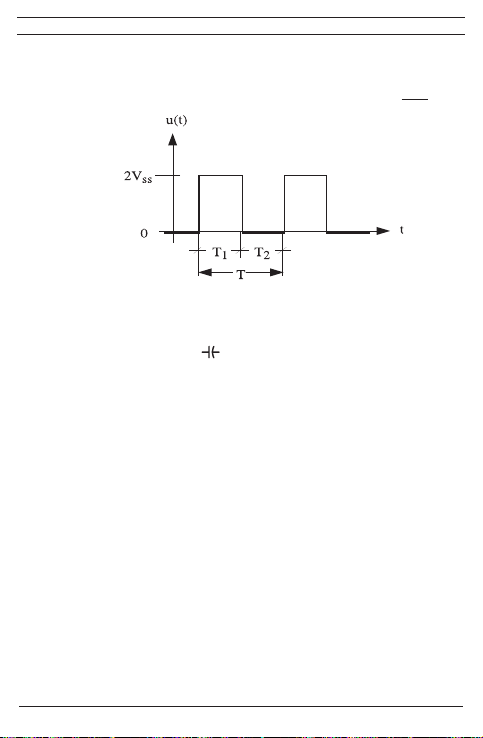
nyomógomb újbóli megnyomásával a kikapcsolhatjuk a tárolás funkciót.
H
5.1.5 A „SELECT” 5 gomb választja ki a forgókapcsoló állásának második vagy
harmadik funkcióját.
Figyelem!
A „%” funkció írja le a periodikus jelek impulzusviszonyát:
5.1.6 A “RANGE” 6 nyomógombbal a méréshatárt választhatjuk ki (a kijelzőről el-
tűnik az “AUTO” jelzés. A nyomógomb hosszabb ideig (1 másodperc) történő
megnyomásával visszatérhetünk az automatikus méréshatár üzemmódba (a
kijelzőn megjelenik az “AUTO” jelzés).
Forgókapcsoló állásban ( ) a „RANGE“ gombnak relatívérték-funkciója
van: „REL ∆“. A gomb megnyomásával a megjelenő mért érték mentésre
kerül, és a lementett mért érték valamint a következő mérési értékek közötti különbség (offset) kerül kijelzésre. A „REL ∆“ relatívérték-funkció teszi
lehetővé a kapacitás-tartomány nullázását nem csatlakoztatott mérőveze-
tékeknél. A gomb újbóli megnyomásával kapcsolhat vissza a normál üzemmódba.
5.1.7 A BENNING MM P3 digitális kijelzője kb. 3 mérést jelez ki másodpercen-
ként
5.1.8 A BENNING MM P3 mérőműszert a forgó kapcsolóval 7 lehet be és kikap-
csolni. A kikapcsolt állás az “OFF”.
5.1.9 A BENNING MM P3 kb. 30 perc után automatikusan kikapcsol (APO, Auto-
Power-Off). Az automatikus kikapcsolás nem aktív, ha korábban a „RANGE”
gombot megnyomtuk.
5.1.10
A hőmérsékleti koefficiens: a mérési érték x 0,2 (az adott mérési pontosság/ C°,
< 18 C° vagy > 28 C°, a 23 C°-on megadott referencia értékre vonatkoztatva.
5.1.11 A BENNING MM P3.készüléket két darab elem 1,5 V LR 44 táplálja.
5.1.12 Ha a telepek feszültsége a BENNING MM P3 működéséhez szükséges
érték alá csökken, a kijelzőn megjelenik egy telep szimbólum .
5.1.13 A telepek élettartama kb. 100 óra (alkáli elemek)
5.1.14 A készülék mérete: (hossz.xszél.xmag.) = 132 x 86 x 19 mm,
A készülék tömege: 130 g védőtok és telepekkel
5.1.15 A biztonsági mérővezetékek 2 mm-es dugós csatlakozással vannak ellátva.
A csatlakoztatott biztonsági mérővezetékek megfelelnek a BENNING MM P3
névleges feszültségének.
84
03/ 2014
BENNING MM P3
[%] =
T1
T

6. Környezeti feltételek
H
- A BENNING MM P3 mérőkészüléket száraz környezetben történő használatra
tervezték.
- A készülék 2000 m tengerszint feletti magasságig használható.
- Túlfeszültség állósági fokozat 300 V-ig III kategória, és 600 V-ig II kategória az
IEC 60664/ IEC 61010-1 szerint.
- Szennyeződési kategória: 2 az IEC 61010-1 szerint.
- Védettség: IP 30 a DIN VDE 0470-1 (IEC/EN 60529)
IP 30 jelentése: védelem a veszélyes részek érintése ellen > 2,5 mm átmérőjű
idegen szilárd testek behatolása esetére (3 - első számjegy). Víz behatolás elleni
védelem nincs (0 - második számjegy).
Üzemi hőmérséklet és a levegő megengedett nedvességtartalma:
0 - 30 °C üzemi hőmérsékletnél a levegő megengedett nedvességtartalma < 80 %,
31 - 40 °C üzemi hőmérsékletnél a levegő megengedett nedvességtartalma < 75 %,
41 - 50 °C üzemi hőmérsékletnél a levegő megengedett nedvességtartalma < 45 %,
- Tárolási hőmérséklet: a BENNING MM P3 mérőkészüléket - 20 °C és + 60 °C
közötti hőmérsékleten (levegő megengedett nedvességtartalma 0 - 80 %) szabad
tárolni. Ekkor a készülékből a telepeket ki kell venni.
7. Villamos adatok
Megjegyzés: a mérési pontosság a
- mért érték relatív értékének, és a
- kijelzett digitek számának (az utolsó számjegy) összegéből áll.
A megadott mérési pontosság 18 °C - 28 °C hőmérséklettartományban és max. 80 %
levegő nedvességtartalom mellet érvényes.
7.1 Egyenfeszültség mérés (Kapcsolóállás: VDC, mVDC)
A bemeneti ellenállás értéke 10 MΩ.
Méréshatár Felbontás Pontosság Túlterhelés védelem
400 mV 0,1 mV ± (a mérési érték 0,7 % + 5 Digit)
4 V 1 mV ± (a mérési érték 0,6 % + 2 Digit)
40 V 10 mV ± (a mérési érték 0,6 % + 2 Digit)
400 V 100 mV ± (a mérési érték 0,6 % + 2 Digit)
600 V 1 V ± (a mérési érték 0,7 % + 5 Digit)
7.2 Váltakozó feszültség mérés (Kapcsolóállás: VAC, Hz, %)
A bemeneti ellenállás értéke 10 MΩ, párhuzamos kapacitás 100 pF.
Méréshatár Felbontás
Pontosság *1 az 50 Hz - 500 Hz
frekvencia tartományban
400 mV 0,1 mV ± (a mérési érték 1,5 % + 5 Digit)
4 V 1 mV ± (a mérési érték 0,9 % + 5 Digit)
40 V 10 mV ± (a mérési érték 0,9 % + 5 Digit)
85
03/ 2014
BENNING MM P3
600 V
DC
600 V
DC
600 V
DC
600 V
DC
600 V
DC
Túlterhelés védelem
600 V
eff
600 V
eff
600 V
eff

H
400 V 100 mV ± (a mérési érték 0,9 % + 5 Digit)
600 V 1 V ± (a mérési érték 0,9 % + 5 Digit)
Az BENNING MM P3 műszereknél a mérési érték az egyenirányított középértékből
van képezve, és effektív értékként kerül kijelzésre
*1 A mérési pontosság szinusz formájú hullámalakra van vonatkoztatva. A nem szi-
nusz formájú hullámalakú jeleknél a kijelzett érték pontatlan lesz.
7.3 Ellenállás mérés (Kapcsolóállás: Ω, , )
Túlterhelés védelem ellenállás mérésnél: 600 V
eff
Méréshatár Felbontás Pontosság Max. Üresjárási feszültség
400 Ω 0,1 Ω ± (a mérési érték 0,9 % + 5 Digit) 0,4 V
4 kΩ 1 Ω ± (a mérési érték 0,9 % + 2 Digit) 0,4 V
40 kΩ 10 Ω ± (a mérési érték 0,9 % + 2 Digit) 0,4 V
400 kΩ 100 Ω ± (a mérési érték 0,9 % + 2 Digit) 0,4 V
4 MΩ 1 kΩ ± (a mérési érték 1,5 % + 5 Digit) 0,4 V
40 MΩ 10 kΩ ± (a mérési érték 1,5 % + 5 Digit) 0,4 V
7.4 Dióda- és folytonosság vizsgálat (Kapcsolóállás: Ω, , )
Túlterhelés védelem: 600 V
A beépített zümmögő megszólal ha a mért R ellenállás kisebb 50 Ω-nál.
eff
Méréshatár Felbontás Max. Mérési áram Max. Üresjárási feszültség
1 mV 1,1 mA 1,5 V
7.5 Kapacitás mérés (Kapcsolóállás: )
Feltételek: A kondenzátorokat kisütött állapotban és megfelelő polaritással kell a
Túlterhelés védelem kapacitás mérésnél: 600 V
műszerre kapcsolni.
eff
Méréshatár Felbontás Pontosság
50 nF 10 pF ± (a mérési érték 5,0 % + 0,2 nF)*
500 nF 100 pF ± (a mérési érték 2,9 % + 5 Digit)
5 µF 1 nF ± (a mérési érték 2,9 % + 5 Digit)
50 µF 10 nF ± (a mérési érték 2,9 % + 5 Digit)
100 µF 100 nF ± (a mérési érték 2,9 % + 5 Digit)
A mérés időtartama a kondenzátor kapacitásától függ, és max. 20 másodpercig
tarthat.
* A mérési pontosság >10 nF mérési értékekre és előzetes, a „RANGE/ REL ∆
6
( )“
gombbal végzett nullázás esetére van meghatározva.
86
03/ 2014
BENNING MM P3
600 V
600 V
eff
eff

7.6 Frekvencia mérés
H
Túlterhelés védelem frekvencia mérésnél: 600 V
7.6.1 Frekvenciatartpmányok négyszögjelekhez (kapcsolóállás: Hz, %)
Méréshatár Felbontás
Mérési pontosság max 5 VSS-nél.
5 Hz 0,001 Hz ± (a mérési érték 0,3 % + 5 Digit) > 1,0 Vss (négyszög)
50 Hz 0,01 Hz ± (a mérési érték 0,3 % + 5 Digit) > 1,0 Vss (négyszög)
500 Hz 0,1 Hz ± (a mérési érték 0,3 % + 5 Digit) > 1,0 Vss (négyszög)
5 kHz 1 Hz ± (a mérési érték 0,3 % + 5 Digit) > 1,0 Vss (négyszög)
50 kHz 10 Hz ± (a mérési érték 0,3 % + 5 Digit) > 1,0 Vss (négyszög)
500 kHz 100 Hz ± (a mérési érték 0,3 % + 5 Digit) > 1,0 Vss (négyszög)
5 MHz 1 kHz ± (a mérési érték 0,3 % + 5 Digit) > 1,0 Vss (négyszög)
7.6.2 F
rekvencia-kijelzés színuszjelekhez (kapcsoló-állás: VAC, Hz, %) és a „SELECT“-
gomb működtetése:
Mérési pontosság: ± (a mért érték 0,3 %-a + 5 jegy) színusjelek esetén
600 V
-ig (10 Hz - 500 Hz) és a váltakozófeszültség tartományban (VAC) a
eff
méréstartromány-végérték 50 %-ánál nagyobb kijelzés-értékekig érvényes
7.7 Impulzuskitöltés négyszögjelekhez (Kapcsolóállás: Hz, %)
Túlterhelés védelem impulzusviszony mérésnél: 600 V
Méréshatár Felbontás
0,1 % - 99,9 % 0,1 % ± (a mérési érték 0,5 % + 3 Digit) > 1,0 Vss (négyszög)
8. MérésaBENNINGMMP3mérőkészülékkel
8.1 Améréselőkészítése
A mérőkészüléket csak a megadott tárolási és munkakörülmények között használja.
A készüléket óvjuk a tartós napsugárzástól.
- A csatlakoztatott fekete és piros biztonsági mérővezetékek megfelelnek az érvényes előírásnak, amennyiben azok sértetlenek.
- A csatlakoztatott fekete és piros biztonsági mérővezetékeket védeni kell szenynyeződés ellen.
- Vizsgáljuk át a mérőzsinórok szigetelését. Ha a szigetelés sérült a vezetéket,
akkor a készüléket azonnal ki kell selejtezni.
- Vizsgáljuk át a mérőzsinórok folytonosságát. Ha a vezeték szakadt, akkor a készüléket azonnal ki kell selejtezni.
- Mielőtt a forgó kapcsolót 7 átkapcsoljuk, a mérőzsinórokat távolítsuk el a mérési
ponttól.
- A BENNING MM P3 mérőkészülék melletti erős zavarforrások instabillá tehetik a
kijelző működését és mérési hibákhoz vezethetnek.
eff
(négyszögjel)
Mérési pontosság 5 VSS max.-ig
(négyszögjel, 5 Hz - 5 kHz)
eff
Érzékenység
Érzékenység
(30 % ≤ % ≤ 70 %)
87
03/ 2014
BENNING MM P3

8.2 Feszültségmérés
H
Figyeljünk a földhöz képest megengedett maximális feszült-
ségre! Villamos veszélyforrás!
A legnagyobb feszültség a multiméter:
- COM 9,
- V-Ω--Hz 8,
A BENNING MM P3 mérőkészülék esetében a maximális feszültség amely a mérőhüvelyek és a föld között felléphet max. 600 V.
- A BENNING MM P3 forgó kapcsolóját 7 a kívánt funkcióba kapcsoljuk (V AC)
vagy (V DC).
- A mérőzsinórokat csatlakoztassuk a mérési pontokra, és a BENNING MM P3
digitális kijelzőjén olvassuk le a mérési értéket.
- A (VAC) forgógomb-állásban a „SELECT“ 5 gombbal lehet végrehajtani az átkapcsolást frekvenciamérésre (a gombot egyszer megnyomni) ill. impulzusviszony
mérésére (a gombot kétszer megnyomni).
Figyelem!
Kis feszültségtartományokban védetlen biztonsági mérővezetékek esetén a nulla Volt
kijelzés beszűrődések következtében elmaradhat. Ellenőrizze a BENNING MM P3
működését a mérőcsúcsok rövidre zárásával!
Ld. 2. ábra Egyenfeszültség mérés,
Ld. 3. ábra Váltakozó feszültség mérés
8.3 Ellenállás mérés
-
A BENNING MM P3 forgó kapcsolóját 7 a kívánt funkcióba kapcsoljuk (Ω, , ).
- A mérőzsinórokat csatlakoztassuk a mérési pontokra, és a BENNING MM P3
digitális kijelzőjén olvassuk le a mérési értéket.
Ld. 4. ábra Ellenállás mérés,
8.4 Dióda vizsgálat
- A BENNING MM P3 forgó kapcsolóját 7 a kívánt funkcióba kapcsoljuk (Ω, ,
) .
- A BENNING MM P3 „SELECT“ 5 gombjával végezze el az átkapcsolást a dióda-
ellenőrzésre ( ) (a gombot egyszer megnyomni).
- A mérőzsinórokat csatlakoztassuk a dióda kapcsaira, és a BENNING MM P3 digitális kijelzőjén olvassuk le a mérési értéket.
- Nyitó irányban egy Si-diódán eső feszültség értéke 0,500 V és 0,900 V között
van. Ha a kijelző ’’000’’-t mutat a dióda zárlatos, ha a kijelző ’’OL’’-t mutat a dióda
szakadt.
- Záró irányban a műszer ’’OL’’-t mutat. Ha a kijelző ’’000’’-t vagy más értéket
mutat a dióda hibás.
Lásd 5 ábra: Dióda vizsgálat
8.5 Folytonosságvizsgálatzümmögővel
-
A BENNING MM P3 forgó kapcsolóját 7 a kívánt funkcióba kapcsoljuk (Ω, , ).
88
03/ 2014
BENNING MM P3

H
- A BENNING MM P3 „SELECT“ 5 gombjával végezze el az átkapcsolást az
átmenet-ellenőrzésre ( ) (a gombot kétszer megnyomni).
- A mérőzsinórokat csatlakoztassuk a dióda kapcsaira.
- Ha a mérési pontok közötti ellenállás 50 Ω alatt van, akkor megszólal a
BENNING MM P3 beépített zümmögője.
Lásd 6. ábra: Folytonosság vizsgálat zümmögővel.
8.6 Kapacitás mérés
A kapacitás méréshez a kondenzátorokat teljesen ki kell sütni!
Akapacitásmérő mérőhüvelyekre soha nem szabad feszültséget
kapcsolni! A rákapcsolt feszültségtől a mérőkészülék meghibá-
sodhatvagytönkremehet.Amérőkészülékkárosodásabalesetveszélyt okozhat!
- A BENNING MM P3 forgó kapcsolóját 7 a kívánt funkcióba kapcsoljuk ( ),
- A kondenzátor polaritását ellenőrizzük, és teljesen süssük ki,
- Esetleg a „RANGE/ REL Δ ( )“ 6 gombbal végezze el a nullázást.
- A mérőzsinórokat csatlakoztassuk a kisütött kondenzátor kapcsaira, és a
BENNING MM P3 digitális kijelzőjén olvassuk le a mérési értéket.
Lásd 7. ábra: Kapacitás mérés.
8.7 Frekvencia mérés
- 5 VSS max.-ig terjedő négyszögjelek méréséhez válassza a 7 forgókapcsolóval
a kívánt funkciót (Hz, %).
- 600 V
-
- A mérőzsinórokat csatlakoztassuk a mérési pontokra, és a BENNING MM P3
Lásd 8. ábrá: Frekvencia-/ impulzusviszony mérés
8.8 Impulzusviszony mérése
- A forgókapcsolóval 7 válassza ki a szükséges funkciót (Hz, %) a
- A BENNING MM P3 „SELECT“ 5 gombjával végezze el az átkapcsolást az
- Érintse a biztonsági mérővezetékeket a mérőpontokhoz, majd a mért értéket
Lásd 8. ábrá: Frekvencia-/ impulzusviszony mérés
9. Karbantartás
-ig terjedő színuszjelek méréséhez válassza a 7 forgókapcsolóval a kí-
eff
vánt funkciót (VAC, Hz, %), és a „SELECT“ gombbal végezze el a frekvenciamé-
résre (Hz) történő átkapcsolást.
Vegyük figyelembe a BENNING MM P3 frekvenciamérés minimális érzékenységét!
digitális kijelzőjén olvassuk le a mérési értéket.
BENNING MM P3-on.
impulzusviszony mérésére (%) (a gombot egyszer megnyomni).
olvassa le a BENNING MM P3 digitális kijelzőjén .
MielőttaBENNINGMMP3mérőkészüléketkinyitjuk,feltétlenülfes-
zültség mentesítsük! Áramütés veszély!
89
03/ 2014
BENNING MM P3

A nyitott BENNING MM P3 mérőkészülékkel történő munkát kizárólag felkészült
H
villamosszakemberekvégezhetnek,megfelelőóvintézkedésekmegtételeután.
Ezért feltétlenül feszültség mentesítsük a mérőkészüléket mielőtt a készülékházat
kinyitjuk.
- Távolítsuk el a mérőzsinórt és a mérőszondát a mérési helyről.
- A forgó kapcsolót 7 állítsuk „OFF” állásba.
9.1 Amérőkészülékbiztosítása
Bizonyos körülmények esetén a BENNING MM P3 mérőkészülék biztonsága már
nem szavatolható. Pl.:
- Szemmel látható sérülések a burkolaton és a biztonsági mérővezetékeken,
- Mérési hibák,
- Hosszabb tárolás következtében fellépő felismerhető károsodások,
- A szokásostól eltérő szállítási igénybevételek következtében fellépő felismerhető
károsodások
Ilyen esetekben a BENNING MM P3 mérőkészüléket azonnal kapcsoljuk ki, és távolítsuk el a mérési helytől, és biztosítsuk az ismételt felhasználás ellen.
9.2 Tisztítás
A mérőkészülék házát kizárólag száraz, tiszta ruhával tisztítsuk. (esetleg speciális
tisztítókendő) Ne használjunk semmiféle oldó- vagy súrolószert a készülék tisztítá-
sához. Feltétlenül ügyeljünk arra, hogy a teleptároló rekeszt és a telep csatlakozókat
a telepekből esetlegesen kifolyó elektrolit nehogy bepiszkítsa.
Ha a telepekből kifolyó elektrolit a teleptároló rekeszt és a telep csatlakozókat bepiszkítja, vagy fehéres lerakódásokat tapasztalunk, itt is csak tiszta száraz törlőruhával
tisztítsuk a készüléket.
9.3 Telepcsere
MielőttaBENNINGMMP3mérőkészüléketkinyitjuk,feltétlenülfes-
zültség mentesítsük! Áramütés veszély!
A BENNING MM P3 mérőkészüléket két darab 1,5 V-os elem (LR 44) táplálja. Telepcsere szükséges (Lásd 9. ábra), ha a kijelzőn a telepjelzés megjelenik.
A telepcserét a következőképpen végezzük:
- Távolítsuk el a mérőzsinórokat a mérési helyről.
- A forgó kapcsolót 7 állítsuk „OFF” állásba.
- Fektesse a BENNING MM P3-t a szemközti oldalára, és csavarja ki a csavart a
burkolat alján.
- Emelje le óvatosan a készülék alját.
A nyomtatott áramköri panelból ne csavarjunk ki csavarokat!
- Emeljük ki a és távolítsuk el a kimerült telepeket.
- Megfelelő polaritással helyezze be az új elemeket a teleptartó rekeszbe úgy,
hogy a plusz pólus felfelé mutasson.
- Pattintsa a készülék alját a készülék felsőrészére, majd csavarozza vissza a csa-
90
03/ 2014
BENNING MM P3
varokat.
H
Lásd 9 ábra: Telepcsere
Figyeljünk a környezet védelmére! A kimerült telepeket ne dobjuk a
háztartásiszemétbe! Gyűjtsük összeéshelyezzük el egyhasznált
elembegyűjtőbenvagyveszélyeshulladéklerakóban!
9.4 Kalibrálás
Ahhoz hogy a megadott mérési pontosságot elérjük a mérőkészüléket rendszeresen
gyári szervizünkben kalibrálni kell. Ajánljuk az évente történő kalibrálást. Kalibráláshoz a készüléket vissza kell küldeni a következő címre:
Benning Elektrotechnik & Elektronik GmbH & Co. KG
Service Center
Robert-Bosch-Str. 20
D - 46397 Bocholt
10.Avédőtokhasználata
A biztonsági mérővezetékek tárolása úgy történik, hogy azokat összecsévéli, és a
tépőzárral a védőtokban őrzi meg.
Lásd 10. ábrá: A védőtok használata
11. Környezetvédelem
Kérjük, hogy a készüléket élettartama végén juttassa el a rendelkezésre álló
visszavételi- illetve begyűjtőhelyre.
91
03/ 2014
BENNING MM P3

I
Istruzioni d’uso
BENNING MM P3
Multimetro digitale per la misurazione
- della tensione continua
- della tensione alternata
- della resistenza
- la prova dei diodi
- la prova di continuità
- della capacità
- della frequenza
- del rapporto scansione
Indice
1. Avvertenze per l’utente
2. Avvertenze sulla sicurezza
3. Dotazione standard
4. Descrizione apparecchio
5. Dati di carattere generale
6. Condizioni ambientali
7. Dati elettrici
8. Misurazione con i BENNING MM P3
9. Manutenzione
10. Uso dell’astuccio di custodia
11. Tutela dell’ambiente
1. Avvertenze per l’utente
Le presenti istruzioni sono destinate a
- elettrotecnici ed a
- personale qualicato in elettrotecnica.
I BENNING MM P3 sono previsti per misure in ambiente asciutto e non devono essere impiegati in circuiti con una tensione nominale superiore a 600 V AC o DC (per
maggiori dettagli vedere il capitolo 6 “Condizioni ambientali”).
Nelle istruzioni d’uso e sui BENNING MM P3 vengono usati i seguenti simboli:
Pericolo di scariche elettriche!
Precede avvertenze, cui ci si deve attenere, per prevenire pericoli per il
personale.
Attenzione, attenersi alla documentazione!
Questo simbolo indica che ci si deve attenere alle avvertenze contenute
nelle istruzioni per evitare pericoli.
92
03/ 2014
BENNING MM P3
 Loading...