

Page 1
D
Bedienungsanleitung
Operating manual
F
Notice d‘emploi
E
Instrucciones de servicio
Návod k obsluze
Οδηγίες xρήσης για το
I
Istruzioni d’uso
Gebruiksaanwijzing
Instrukcja obsługi
Instructiuni de folosire
Инструкция по эксплуатации
индикатора напряжения
S
Bruksanvisning
Kullanma Talimati
BENNING MM 9/ 10
Page 2
D F E I S
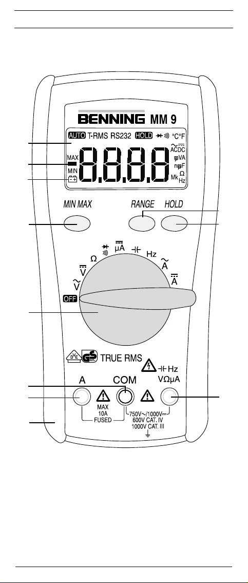
BENNING MM 9
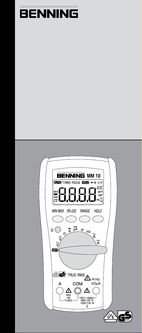
Bild 1a: Gerätefrontseite
Fig. 1a: Front tester panel
Fig. 1a: Panneau avant de l‘appareil
Fig. 1a: Parte frontal del equipo
obr. 1a: Přední strana přístroje
фигура 1a: Μπροστινή όψη
03/ 2011
BENNING MM 9/ 10
ill. 1a: Lato anteriore apparecchio
Fig. 1a: Voorzijde van het apparaat
Rys.1a: Panel przedni przyrządu
Imaginea 1a: Partea frontală a aparatului
рис. 1a. Вид спереди мультиметра
Fig. 1a: Framsida
Resim 1a: Cihaz ön yüzü
Page 3
D F E I S
BENNING MM 10
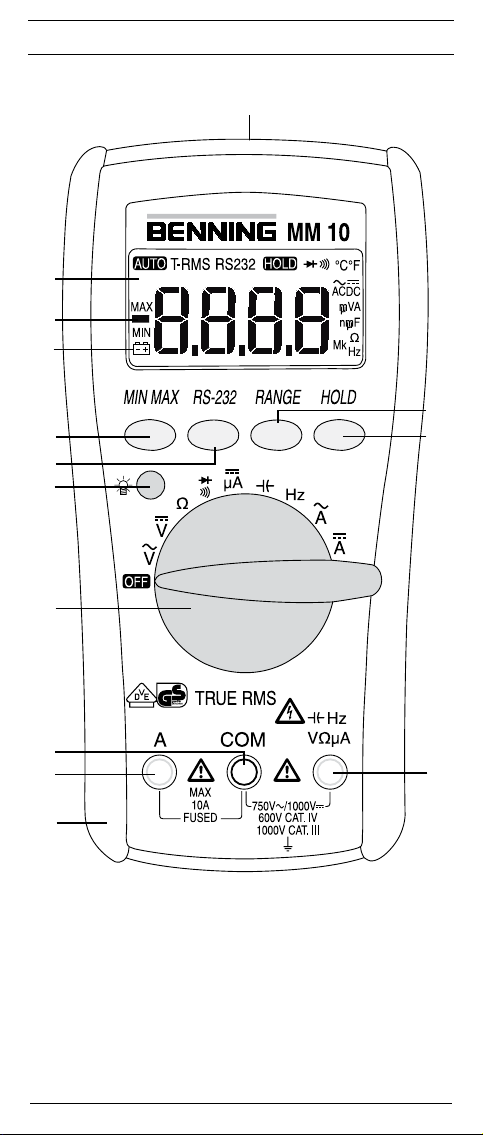
Bild 1b: Gerätefrontseite
Fig. 1b: Front tester panel
Fig. 1b: Panneau avant de l‘appareil
Fig. 1b: Parte frontal del equipo
obr. 1b: Přední strana přístroje
фигура 1b: Μπροστινή όψη
03/ 2011
BENNING MM 9/ 10
ill. 1b: Lato anteriore apparecchio
Fig. 1b: Voorzijde van het apparaat
Rys.1b: Panel przedni przyrządu
Imaginea 1b: Partea frontală a aparatului
рис. 1b. Вид спереди мультиметра
Fig. 1b: Framsida
Resim 1b: Cihaz ön yüzü
Page 4

D F E I S
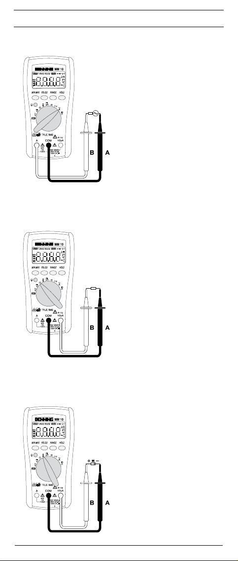
Bild 2: Gleichspannungsmessung
Fig. 2: Direct voltage measurement
Fig. 2: Mesure de tension continue
Fig. 2: Medición de tension contínua
obr. 2: Měření stejnosměrného napětí
фигура 2: DC-μέτρηση
ill. 2: Misura tensione continua
Fig. 2: Meten van gelijkspanning
Rys.2: Pomiar napięcia stałego
Imaginea 2: Măsurarea tensiunii continue
рис. 2. Измерение напряжения
постоянного тока
Fig. 2: Likspänningsmätning
Resim 2: Doğru Gerilim Ölçümü
Bild 3: Wechselspannungsmessung
Fig. 3: Alternating voltage measurement
Fig. 3: Mesure de tension alternative
Fig. 3: Medición de tensión alterna
obr. 3: Měření střídavého napětí
фигура 3: AC μέτρηση
ill. 3: Misura tensione alternata
Fig. 3: Meten van wisselspanning
Rys.3: Pomiar napięcia przemiennego
Imaginea 3: Măsurarea tensiunii alternative
рис. 3. Измерение напряжения
переменного тока
Fig. 3: Växelspänningsmätning
Resim 3: Alternatif Gerilim Ölçümü
03/ 2011
Bild 4: Gleichstrommessung
Fig. 4: DC current measurement
Fig. 4: Mesure de courant continu
Fig. 4: Medición de corriente contínua
obr. 4: Měření stejnosměrného proudu
фигура 4: DC-μέτρηση
ill. 4: Misura corrente continua
Fig. 4: Meten van gelijkstroom
Rys.4: Pomiar prądu stałego
Imaginea 4:
Măsurarea curentului continuu
рис. 4.
Измерение величины постоянного тока
Fig. 4: Likströmsmätning
Resim 4: Doğru Akım Ölçümü
BENNING MM 9/ 10
Page 5
D F E I S
Bild 5: Wechselstrommessung
Fig. 5: AC current measurement
Fig. 5: Mesure de courant alternatif
Fig. 5: Medición de corriente alterna
obr. 5: Měření střídavého proudu
фигура 5: AC-μέτρηση
ill. 5: Misura corrente alternata
Fig. 5: Meten van wisselstroom
Rys.5: Pomiar prądu przemiennego
Imaginea 5: Măsurarea curentului alternativ
рис. 5.
Измерение величины переменного тока
Fig. 5: Växelströmsmätning
Resim 5: Alternatif Akım Ölçümü
Bild 6: Widerstandsmessung
Fig. 6: Resistance measurement
Fig. 6: Mesure de résistance
Fig. 6: Medición de resistencia
obr. 6: Měření odporu
фигура 6: Μέτρηση αντίστασης
ill. 6: Misura di resistenza
Fig. 6: Weerstandsmeting
Rys.6: Pomiar rezystancji
Imaginea 6: Măsurarea rezistenţei
рис. 6. Измерение сопротивления
Fig. 6: Resistansmätning
Resim 6: Direnç Ölçümü
03/ 2011
Bild 7: Diodenprüfung
Fig. 7: Diode Testing
Fig. 7: Contrôle de diodes
Fig. 7: Vericación de diodos
obr. 7: test diod
фигура 7: Έλεγχος διόδου
ill. 7: Prova diodi
Fig. 7: Diod-test
Rys.7: Pomiar diody
Imaginea 7: Testarea diodelor
рис. 7 Проверка диодов
Fig. 7: Diodecontrole
Resim 7: Diyot Kontrolü
BENNING MM 9/ 10
Page 6
D F E I S
Bild 8: Durchgangsprüfung mit Summer
Fig. 8: Continuity Testing with buzzer
Fig. 8: Contrôle de continuité avec roneur
Fig. 8: Control de continuidad con vibrador
obr. 8: Zkoušku obvodu
фигура 8: Έλεγχος συνέχειας με βομβητή
ill. 8: Prova di continuità con cicalino
Fig. 8: Doorgangstest met akoestisch signaal
Rys.8: Sprawdzenie ciągłości obwodu
Imaginea 8: Vericarea continuităţii cu buzzer
рис. 8. Проверка целостности цепи
Fig. 8: Genomgångstest med summer
Resim 8: Sesli uyarıcı ile süreklilik ölçümü
Bild 9: Kapazitätsmessung
Fig. 9: Capacity Testing
Fig. 9: Mesure de capacité
Fig. 9: Medición de capacidad
obr. 9: Měření kapacity
фигура 9: Μέτρηση χωρητικότητας
ill. 9: Misura di capacità
Fig. 9: Capaciteitsmeting
Rys.9: Pomiar pojemności
Imaginea 9: Măsurarea capacităţii
рис. 9 Измерение емкости
Fig. 9: Kapacitansmätning
Resim 9: Kapasite Ölçümü
03/ 2011
Bild 10: Frequenzmessung
Fig. 10: Frequency measurement
Fig. 10: Mesure de fréquence
Fig. 10: Medición de frecuencia
obr. 10: Měření frekvence
фигура 10: Μέτρηση συχνότητας
ill. 10: Misura di frequenza
Fig. 10: Frequentiemeting
Rys.10: Pomiar częstotliwości
Imaginea 10: Măsurarea frecvenţei
рис. 10 Измерение частоты
Fig. 10: Frekvensmätning
Resim 10: Frekans Ölçümü
BENNING MM 9/ 10
Page 7
D F E I S
Bild 11: Batteriewechsel
Fig. 11: Battery replacement
Fig. 11: Remplacement de la pile
Fig. 11: Cambio de pila
obr. 11: Výměna baterií
фигура 11: Αντικατάσταση μπαταρίας
ill. 11: Sostituzione batterie
Fig. 11: Vervanging van de batterijen
Rys.11: Wymiana baterii
Imaginea 11: Schimbarea bateriilor
рис. 11 Замена батареи
Fig. 11: Batteribyte
Resim 11: Batarya Değişimi
Bild 12: Sicherungswechsel
Fig. 12: Fuse replacement
Fig. 12: Remplacement des fusibles
Fig. 12: Cambio de fusible
obr. 12: Výměna pojistek
фигура 12: αντικατάσταση ασφάλειας
ill. 12: Sostituzione fusibile
Fig. 12: Vervanging van de smeltzekeringen
Rys.12: Wymiana bezpiecznika
Imaginea 12: Schimbarea siguranţelor
рис. 12 Замена предохранителей
Fig. 12: Säkringsbyte
Resim 12: Sigorta Değişimi
03/ 2011
Bild 13: Aufwicklung der Sicherheitsmessleitung
Fig. 13: Wrapping up the safety test leads
Fig. 13: Enroulement du câble de mesure de sécurité
Fig. 13: Arrollamiento de la conducción protegida de
medición
obr. 13: navíjení měřících kabelů
фигура 13: Τυλίξτε τα καλώδια μέτρησης
ill. 13: Avvolgimento dei cavetti di sicurezza
Fig. 13: Wikkeling van veiligheidsmeetsnoeren
Rys.13: Zwijanie przewodów pomiarowych
Imaginea 13: Înfăşurarea relor de măsurare pe rama din
cauciuc
рис. 13 Намотка измерительных проводов
Fig. 13: Placering av säkerhetsmätsladdar
Resim 13:
Emniyet Ölçüm tesisatının sarılması
Bild 14: Aufstellung
Fig. 14: Standing
Fig. 14: Installation
Fig. 14: Colocación
obr. 14: postavení
фигура 14: Κρατώντας όρθιο
ill. 14: Posizionamento
Fig. 14: Opstelling van de multimeter
Rys.14: Przyrząd w pozycji stojącej
Imaginea 14: Poziţionarea pe verticală a aparatului
рис. 14 Установка прибора
Fig. 14: Instrumentstöd
Resim 14: Multimetre ‘nun kurulumu
BENNING MM 9/ 10
Page 8
D
Bedienungsanleitung
BENNING MM 9/ 10
Digital-Multimeter zur
- Gleichspannungsmessung
- Wechselspannungsmessung
- Gleichstrommessung
- Wechselstrommessung
- Widerstandsmessung
- Diodenprüfung
- Durchgangsprüfung
- Kapazitätsmessung
- Frequenzmessung
Inhaltsverzeichnis
1. Benutzerhinweise
2. Sicherheitshinweise
3. Lieferumfang
4. Gerätebeschreibung
5. Allgemeine Angaben
6. Umgebungsbedingungen
7. Elektrische Angaben
8. Messen mit dem BENNING MM 9/ 10
9. Instandhaltung
10. Anwendung des Gummi-Schutzrahmens
11. Technische Daten des Messzubehörs
12. Umweltschutz
1. Benutzerhinweise
Diese Bedienungsanleitung richtet sich an
- Elektrofachkräfte und
- elektrotechnisch unterwiesene Personen.
Das BENNING MM 9/ 10 ist zur Messung in trockener Umgebung vorgesehen. Es darf nicht in Stromkreisen mit einer höheren Nennspannung als
1000 V DC und 750 V AC eingesetzt werden (Näheres hierzu im Abschnitt 6.
„Umgebungsbedingungen“).
In der Bedienungsanleitung und auf dem BENNING MM 9/ 10 werden folgende
Symbole verwendet:
Warnung vor elektrischer Gefahr!
Steht vor Hinweisen, die beachtet werden müssen, um Gefahren für
Menschen zu vermeiden.
Achtung Dokumentation beachten!
Das Symbol gibt an, dass die Hinweise in der Bedienungsanleitung zu
beachten sind, um Gefahren zu vermeiden.
Dieses Symbol auf dem BENNING MM 9/ 10 bedeutet, dass das
BENNING MM 9/ 10 schutzisoliert (Schutzklasse II) ausgeführt ist.
Dieses Symbol auf dem BENNING MM 9/ 10 weist auf die eingebauten
Sicherungen hin.
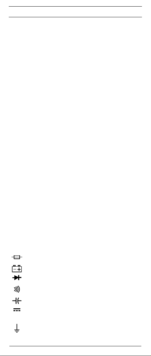
Dieses Symbol erscheint in der Anzeige für eine entladene Batterie.
Dieses Symbol kennzeichnet den Bereich „Diodenprüfung“.
Dieses Symbol kennzeichnet den Bereich „Durchgangsprüfung“.
Der Summer dient der akustischen Ergebnisausgabe.
Dieses Symbol kennzeichnet den Bereich „Kapazitätsprüfung“.
(DC) Gleich- Spannung oder Strom.
(AC) Wechsel- Spannung oder Strom.
Erde (Spannung gegen Erde).
03/ 2011
BENNING MM 9/ 10
1
Page 9

D
2. Sicherheitshinweise
Das Gerät ist gemäß
DIN VDE 0411 Teil 1/ EN 61010-1
geprüft und zugelassen und hat das Werk in einem sicherheitstechnisch einwandfreien Zustand verlassen.
Um diesen Zustand zu erhalten und einen gefahrlosen Betrieb sicherzustellen,
muss der Anwender die Hinweise und Warnvermerke beachten, die in dieser
Anleitung enthalten sind.
Das Gerät darf nur in Stromkreisen der Überspannungs-
kategorie III mit max. 1000 V Leiter gegen Erde oder Über
spannungskategorie IV mit 600 V Leiter gegen Erde benutzt
werden.
Hierzu sind geeignete Messleitungen zu verwenden. Bei Messungen innerhalb der Messkategorie III oder der Messkategorie
IV darf das hervorstehende leitfähige Teil einer Kontaktspitze
der Messleitung nicht länger als 4 mm sein.
Vor Messungen innerhalb der Messkategorie III und der Mess-
kategorie IV müssen, die dem Set beigestellten, mit CAT III und
CAT IV gekennzeichneten, Aufsteckkappen auf die Kontaktspit-
zen aufgesteckt werden. Diese Maßnahme dient dem Benutzerschutz.
Beachten Sie, dass Arbeiten an spannungsführenden Teilen
und Anlagen grundsätzlich gefährlich sind. Bereits Span-
nungen ab 30 V AC und 60 V DC können für den Menschen
lebensgefährlich sein.
Vor jeder Inbetriebnahme überprüfen Sie das Gerät und die
Leitungen auf Beschädigungen.
Ist anzunehmen, dass ein gefahrloser Betrieb nicht mehr möglich ist, ist das
Gerät außer Betrieb zu setzen und gegen unbeabsichtigten Betrieb zu sichern.
Es ist anzunehmen, dass ein gefahrloser Betrieb nicht mehr möglich ist,
-
wenn das Gerät oder die Messleitungen sichtbare Beschädigungen aufweisen,
- wenn das Gerät nicht mehr arbeitet,
- nach längerer Lagerung unter ungünstigen Verhältnissen,
- nach schweren Transportbeanspruchungen.
Um eine Gefährdung auszuschließen
berühren Sie die Messleitungen nicht an den blanken
Messspitzen,
- stecken Sie die Messleitungen in die entsprechend gekennzeichneten Messbuchsen am Multimeter
3. Lieferumfang
Zum Lieferumfang des BENNING MM 9/ 10 gehören:
3.1 ein Stück BENNING MM 9/ 10,
3.2 ein Stück Software PC-Win MM 10 ( BENNING MM 10)
3.3 ein Stück serielles Datenkabel mit USB 2.0 kompatiblen Anschluss
(BENNING MM 10)
3.4 ein Stück Sicherheitsmessleitung, rot (L = 1,4 m),
3.5 ein Stück Sicherheitsmessleitung, schwarz (L = 1,4 m),
3.6 ein Stück Gummi-Schutzrahmen,
3.7 ein Stück Kompakt-Schutztasche,
3.8 eine 9-V-Blockbatterie und eine Sicherung zur Erstbestückung sind im
Gerät eingebaut,
3.9
eine Bedienungsanleitung.
Hinweis auf Verschleißteile:
- Das BENNING MM 9/ 10 enthält eine Sicherung zum Überlastschutz:
Ein Stück Sicherung Nennstrom 10 A flink (500 V), D = 6,35 mm, L = 32 mm
(T.Nr. 749726)
- Das BENNING MM 9/ 10 wird durch eine eingebaute 9-V-Blockbatterie
(IEC 6 LR 61) gespeist.
- Die oben genannten Sicherheitsmessleitungen (geprüftes Zubehör) ent-
sprechen CAT III 1000 V und sind für einen Strom von 10 A zugelassen.
4. Gerätebeschreibung
siehe Bild 1a, 1b: Gerätefrontseite
Die in den Bildern 1a und 1b angegebenen Anzeige- und Bedienelemente
03/ 2011
BENNING MM 9/ 10
2
Page 10

D
werden wie folgt be zeichnet:
Digitalanzeige, für den Messwert und die Anzeige der Bereichs über schrei tung,
Polaritätsanzeige,
Batterieanzeige, erscheint bei entladener Batterie,
MIN/MAXTaste, Speicherung des höchsten und niedrigsten Messwertes,
RS232Taste, Aktivierung der optischen Schnittstelle zur Übertragung der
Messwerte ( BENNING MM 10),
RANGE-Taste, Umschaltung automatischer/ manueller Messbereich,
HOLDTaste, Speicherung des angezeigten Messwertes,
Taste (gelb), Displaybeleuchtung ( BENNING MM 10),
Drehschalter, für Wahl der Messfunktion,
Buchse (positive1), für V, Ω, µA, , Hz,
COMBuchse, gemeinsame Buchse für Strom-, Spannungs-, Widerstands-,
Frequenz-, Kapazitätsmessungen, Durchgangs- und Diodenprüfung,
Buchse (positive1), für A-Bereich, für Ströme bis 10 A
Gummi-Schutzrahmen
optische Schnittstelle, zur Aufnahme des am Datenkabels befindlichen
Adapters ( BENNING MM 10)
1) Hierauf bezieht sich die automatische Polaritätsanzeige für Gleichstrom und -spannung
5. Allgemeine Angaben
5.1 Allgemeine Angaben zum Multimeter
5.1.1 Die Digitalanzeige ist als 4-stellige Flüssigkristallanzeige mit 16 mm
Schrifthöhe mit Dezimalpunkt ausgeführt. Der größte Anzeigewert ist 6000.
5.1.2 Die Polaritätsanzeige wirkt automatisch. Es wird nur eine Polung
entgegen der Buchsendefinition mit „-“ angezeigt.
5.1.3 Die Bereichsüberschreitung wird mit „OL” oder „-OL” und teilweise mit
einer akustischen Warnung angezeigt.
Achtung, keine Anzeige und Warnung bei Überlast!
5.1.4 Die „MIN/MAX“-Tastenfunktion erfasst und speichert automatisch
den höchsten und niedrigsten Messwert. Durch Tastenbetätigung werden folgende Werte angezeigt:
„MAX“ zeigt den gespeicherten höchsten und „MIN“ den niedrigsten
Wert an. Die fortlaufende Erfassung des MAX-/ MIN- Wertes kann
durch Betätigung der Taste „HOLD“ gestoppt, bzw gestartet werden.
Durch längeren Tastendruck (2 Sekunden) auf die Taste „MIN/MAX“
wird in den Normalmodus zurückgeschaltet.
5.1.5 Die RS-232-Taste aktiviert die optische Infrarot-Schnittstelle zur
Übertragung der Messwerte vom BENNING MM 10 zu einem PC/
Laptop. Der PC/ Laptop ist durch die optische Infrarot-Schnittstelle
galvanisch vom Messsignal getrennt. Die Aktivierung erfolgt mit der
gleichzeitigen Einblendung von „RS232“ im Display.
5.1.6 Die Bereichstaste „RANGE“ dient zur Weiterschaltung der manuellen Messbereiche bei gleichzeitiger Ausblendung von „AUTO“ im
Display. Durch längeren Tastendruck (2 Sekunden) wird die automatische Bereichswahl gewählt (Anzeige „AUTO“).
5.1.7 Messwertspeicherung „HOLD“: Durch Betätigen der Taste „HOLD“
lässt sich das Messergebnis speichern. Im Display wird gleichzeitig das
Symbol „HOLD“ eingeblendet. Erneutes Betätigen der Taste schaltet in
den Messmodus zurück.
5.1.8 Taste (gelb) schaltet die Beleuchtung des Displays an. Ausschaltung
durch erneute Tastenbetätigung.
5.1.9 Die Messrate des BENNING MM 9/ 10 beträgt nominal 1,5 Messungen
pro Sekunde für die Digitalanzeige.
5.1.10 Das BENNING MM 9/ 10 wird durch den Drehschalter ein- oder
ausgeschaltet. Ausschaltstellung „OFF“.
5.1.11 Das BENNING MM 9/ 10 schaltet sich nach ca. 10 min selbsttätig ab
(APO, Auto-Power-Off). Es schaltet sich wieder ein, wenn eine Taste
oder der Drehschalter betätigt wird. Ein Summerton signalisiert die
selbsttätige Abschaltung des Gerätes. Die Abschaltung ist nicht aktiv,
wenn vorher die „RS-232“-Taste betätigt wurde.
5.1.12 Temperaturkoeffizient des Messwertes: 0,15 x (angegebene Messgenauigkeit)/ °C < 18 °C oder > 28 °C, bezogen auf den Wert bei der
Referenztemperatur von 23 °C.
5.1.13 Das BENNING MM 9/ 10 wird durch eine 9-V-Blockbatterie gespeist
(IEC 6 LR 61).
5.1.14 Wenn die Batteriespannung unter die vorgesehene Arbeitsspannung
des BENNING MM 9/ 10 sinkt, erscheint in der Anzeige ein Batteriesymbol .
5.1.15 Die Lebensdauer der Batterie beträgt etwa 300 Stunden (Alkalibatterie).
5.1.16 Geräteabmessungen:
(L x B x H) = 158 x 76 x 38 mm ohne Gummi-Schutzrahmen
(L x B x H) = 164 x 82 x 44 mm mit Gummi-Schutzrahmen
03/ 2011
BENNING MM 9/ 10
3
Page 11

D
Gerätegewicht:
265 g ohne Gummi-Schutzrahmen
365 g mit Gummi-Schutzrahmen
5.1.17 Die mitgelieferten Sicherheitsmessleitungen sind ausdrücklich für die
Nenn spannung und dem Nennstrom des BENNING MM 9/ 10 geeignet.
5.1.18 Das BENNING MM 9/ 10 wird durch einen Gummi-Schutzrahmen
vor mechanischer Beschädigung geschützt. Der Gummi-Schutzrahmen
ermöglicht es, das BENNING MM 9/ 10 während der Messung aufzustellen oder aufzuhängen.
5.1.19
Das BENNING MM 10 besitzt kopfseitig eine optische Schnittstelle .
Diese dient der galvanischen Trennung des Messsignals zu einem PC/
Laptop. Das beigefügte Datenkabel dient der Messdatenübertragung und
ist mit einem USB 2.0 kompatiblen Anschluss ausgerüstet.
6. Umgebungsbedingungen
- Das BENNING MM 9/ 10 ist für Messungen in trockener Umgebung vorge-
sehen,
- Barometrische Höhe bei Messungen: Maximal 2000 m,
- Überspannungskategorie/ Aufstellungskategorie: IEC 60664-1/ IEC 61010-1
→ 600 V Kategorie IV; 1000 V Kategorie III,
- Verschmutzungsgrad: 2,
- Schutzart: IP 30 DIN VDE 0470-1 IEC/EN 60529
IP 30 bedeutet: Schutz gegen Zugang zu gefährlichen Teilen und Schutz
gegen feste Fremdkörper > 2,5 mm Durchmesser, (3 - erste Kennziffer).
Kein Wasserschutz, (0 - zweite Kennziffer).
- Arbeitstemperatur und relative Luftfeuchte:
Bei Arbeitstemperatur von 0 °C bis 30 °C: relative Luftfeuchte kleiner 80 %,
Bei Arbeitstemperatur von 31 °C bis 40 °C: relative Luftfeuchte kleiner 75 %,
Bei Arbeitstemperatur von 41 °C bis 50 °C: relative Luftfeuchte kleiner 45 %,
- Lagerungstemperatur: Das BENNING MM 9/ 10 kann bei Temperaturen
von - 20 °C bis + 60 °C (Luftfeuchte 0 bis 80 %) gelagert werden. Dabei ist
die Batterie aus dem Gerät herauszunehmen.
7. Elektrische Angaben
Bemerkung: Die Messgenauigkeit wird angegeben als Summe aus
- einem relativen Anteil des Messwertes und
- einer Anzahl von Digit (d.h. Zahlenschritte der letzten Stelle).
Diese Messgenauigkeit gilt bei Temperaturen von 18 °C bis 28 °C und einer
relativen Luftfeuchtigkeit kleiner 80 %.
7.1 Gleichspannungsbereiche
Der Eingangswiderstand beträgt 10 MΩ (im 400 mV-Bereich 1 GΩ).
Messbereich Auflösung Messgenauigkeit Überlastschutz
600 mV 100 µV ± (0,5 % des Messwertes + 2 Digit) 1000 V
6 V 1 mV ± (0,5 % des Messwertes + 2 Digit) 1000 V
60 V 10 mV ± (0,5 % des Messwertes + 2 Digit) 1000 V
600 V 100 mV ± (0,5 % des Messwertes + 2 Digit) 1000 V
1000 V 1 V ± (0,5 % des Messwertes + 2 Digit) 1000 V
7.2 Wechselspannungsbereiche
Der Eingangswiderstand beträgt 10 M parallel 100 pF.
Messbereich Auflösung
600 mV 100 µV
Messgenauigkeit
im Frequenzbereich 50 Hz - 500 Hz
± (0,9 % des Messwertes + 5 Digit)
6 V 1 mV ± (0,9 % des Messwertes + 5 Digit)
60 V 10 mV ± (0,9 % des Messwertes + 5 Digit)
600 V 100 mV ± (0,9 % des Messwertes + 5 Digit)
750 V 1 V ± (0,9 % des Messwertes + 5 Digit)
Der Messwert des BENNING MM 9/ 10 wird als echter Effektivwert (TRUE
RMS) gewonnen und angezeigt.
*1
Die Messgenauigkeit ist spezifiziert für eine Sinuskurvenform und gültig für
Anzeigewerte unter 4000 Digit. Für Anzeigewerte größer 4000 Digit sind
zu der spezifizierten Messgenauigkeit 0,6% zu addieren. Bei nicht sinusförmigen Kurvenformen unter 2000 Digit wird der Anzeigewert ungenauer.
So ergibt sich für folgende Crest-Faktoren ein zusätzlicher Fehler:
Crest-Factor von 1,4 bis 3,0 zusätzlicher Fehler ± 1,5 %
*2
Gültig für Sinuskurvenform 50 Hz/ 60 Hz
03/ 2011
BENNING MM 9/ 10
*1
*2
*2
*2
*2
*2
DC
DC
DC
DC
DC
Überlastschutz
750 V
eff
750 V
eff
750 V
eff
750 V
eff
750 V
eff
4
Page 12
D
7.3 Gleichstrombereiche
Überlastungsschutz:
- 600 V
am µA – Eingang,
eff
- 10 A (500 V)-Sicherung, flink am 10 A - Eingang,
Messbereich Auflösung Messgenauigkeit
600 µA 0,1 µA ± (1,0 % des Messwertes + 2 Digit) < 4 mV/ µA
6000 µA 1 µA ± (1,0 % des Messwertes + 2 Digit) < 4 mV/ µA
6 A 1 mA ± (1,0 % des Messwertes + 2 Digit) 2 V max.
10 A 10 mA ± (1,0 % des Messwertes + 2 Digit) 2 V max.
7.4 Wechselstrombereiche
Überlastungsschutz:
- 10 A (500 V)-Sicherung, flink am 10 A - Eingang,
Messbereich Auflösung
Messgenauigkeit *
im Frequenzbereich 50 Hz - 500 Hz
1
6 A 1 mA ± (1,5 % des Messwertes + 5 Digit) 2 V max.
10 A 10 mA ± (1,5 % des Messwertes + 5 Digit) 2 V max.
Der Messwert des BENNING MM 9/ 10 wird als echter Effektivwert (TRUE
RMS) gewonnen und angezeigt.
*1
Die Messgenauigkeit ist spezifiziert für eine Sinuskurvenform und gültig für
Anzeigewerte unter 4000 Digit. Für Anzeigewerte größer 4000 Digit sind
zu der spezifizierten Messgenauigkeit 0,6 % zu addieren. Bei nicht sinusförmigen Kurvenformen unter 2000 Digit wird der Anzeigewert ungenauer.
So ergibt sich für folgende Crest-Faktoren ein zusätzlicher Fehler:
Crest-Factor von 1,4 bis 3,0 zusätzlicher Fehler ± 1,5 %
7.5 Widerstandsbereiche
Überlastschutz bei Widerstandsmessungen: 600 V
eff
Messbereich Auflösung Messgenauigkeit
600 Ω 0,1 Ω ± (0,7 % des Messwertes + 2 Digit) 1,3 V
6 kΩ 1 Ω ± (0,7 % des Messwertes + 2 Digit) 1,3 V
60 kΩ 10 Ω ± (0,7 % des Messwertes + 2 Digit) 1,3 V
600 kΩ 100 Ω ± (0,7 % des Messwertes + 2 Digit) 1,3 V
6 MΩ 1 kΩ ± (1,0 % des Messwertes + 2 Digit) 1,3 V
60 MΩ 10 kΩ ± (1,5 % des Messwertes + 2 Digit) 1,3 V
7.6 Dioden und Durchgangsprüfung
Die angegebene Messgenauigkeit gilt im Bereich zwischen 0,4 V und 0,8 V.
Überlastschutz bei Diodenprüfungen: 600 V
Der eingebaute Summer ertönt bei einem Widerstand R kleiner 100 Ω.
Mess-
Auflösung Messgenauigkeit
bereich
10 mV
± (1,5 % des Messwertes + 5 Digit)
eff
Spannungsabfall
Spannungsabfall
Max. Leerlauf-
spannung
Max.
Messstrom
Max. Leerlauf-
1,5 mA 3,0 V
spannung
7.7 Kapazitätsbereiche
Bedingungen: Kondensatoren entladen und entsprechend der angegebenen
Überlastschutz bei Kapazitätsmessungen: 600 V
Polarität anlegen.
eff
Messbereich Auflösung Messgenauigkeit
6 nF 1 pF ± (1,9 % des Messwertes + 8 Digit)
60 nF 10 pF ± (1,9 % des Messwertes + 8 Digit)
600 nF 100 pF ± (1,9 % des Messwertes + 8 Digit)
6 µF 1 nF ± (1,9 % des Messwertes + 8 Digit)
60 µF 10 nF ± (1,9 % des Messwertes + 8 Digit)
600 µF 100 nF ± (1,9 % des Messwertes + 8 Digit)
6 mF 1 µF ± (1,9 % des Messwertes + 8 Digit)
03/ 2011
BENNING MM 9/ 10
5
Page 13

D
7.8 Frequenzbereiche
Überlastschutz bei Frequenzmessungen: 600 V
Mess-
bereich
Auf-
lösung
Messgenauigkeit für
6 kHz 1 Hz ± (0,01 % des Messwertes + 1 Digit) 100 mV
60 kHz 10 Hz ± (0,01 % des Messwertes + 1 Digit) 100 mV
600 kHz 100 Hz ± (0,01 % des Messwertes + 1 Digit) 100 mV
6 MHz 1 kHz ± (0,01 % des Messwertes + 1 Digit) 250 mV
60 MHz 10 kHz ± (0,01 % des Messwertes + 1 Digit) 1 V
Die minimale Empndlichkeit für Frequenzen unterhalb von 20 Hz beträgt
1,5 V
.
eff
8. Messen mit dem BENNING MM 9/ 10
8.1 Vorbereiten der Messung
Benutzen und lagern Sie das BENNING MM 9/ 10 nur bei den angegebenen
Lager- und Arbeitstemperaturbedingungen, vermeiden Sie dauernde Sonneneinstrahlung.
- Angaben von Nennspannung und Nennstrom auf den Sicherheitsmess leitungen
überprüfen. Die zum Lieferumfang gehörenden Sicherheitsmess lei tungen entsprechen in Nennspannung und Nennstrom dem BENNING MM 9/ 10.
- Isolation der Sicherheitsmessleitungen überprüfen. Wenn die Isolation
beschädigt ist, sind die Sicherheitsmessleitungen sofort auszusondern.
- Sicherheitsmessleitungen auf Durchgang prüfen. Wenn der Leiter in der
Sicherheitsmessleitung unterbrochen ist, sind die Sicherheitsmessleitungen
sofort auszusondern.
- Bevor am Drehschalter eine andere Funktion gewählt wird, müssen die
Sicherheitsmessleitungen von der Messstelle getrennt werden.
- Starke Störquellen in der Nähe des BENNING MM 9/ 10 können zu instabi-
ler Anzeige und zu Messfehlern führen.
8.2 Spannungs- und Strommessung
Maximale Spannung gegen Erdpotential beachten!
Elektrische Gefahr!
Die höchste Spannung, die an den Buchsen,
- COM-Buchse
- Buchse für V, Ω, µA, , Hz
- Buchse für 10 A-Bereich
des BENNING MM 9/ 10 gegenüber Erde liegen darf, beträgt 1000 V.
Elektrische Gefahr!
Maximale Schaltkreisspannung bei Strommessung 500 V! Bei
Sicherungsauslösung über 500 V ist eine Beschädigung des
Gerätes möglich. Von einem beschädigten Gerät kann eine
elektrische Gefährdung ausgehen!
eff
5 V
max.
eff
Min. Empfind-
lichkeit
eff
eff
eff
eff
eff
8.2.1 Spannungsmessung
- Mit dem Drehschalter die gewünschte Funktion (V AC) oder (V DC) am
BENNING MM 9/ 10 wählen.
- Die schwarze Sicherheitsmessleitung mit der COM-Buchse am
BENNING MM 9/ 10 kontaktieren.
- Die rote Sicherheitsmessleitung mit der Buchse für V, , µA, , Hz am
BENNING MM 9/ 10 kontaktieren.
- Die Sicherheitsmessleitungen mit den Messpunkten kontaktieren, Messwert
an der Digitalanzeige am BENNING MM 9/ 10 ablesen.
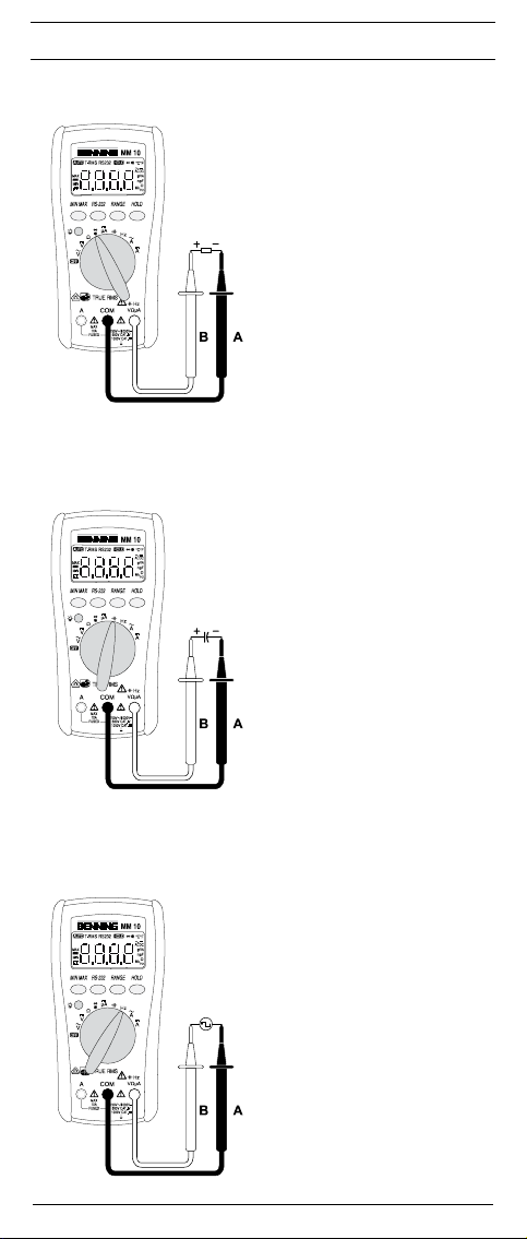
siehe Bild 2: Gleichspannungsmessung
siehe Bild 3: Wechselspannungsmessung
8.2.2 Strommessung
- Mit dem Drehschalter den gewünschten Bereich und Funktion (A AC)
oder (A DC) am BENNING MM 9/ 10 wählen.
- Die schwarze Sicherheitsmessleitung mit der COM-Buchse am
BENNING MM 9/ 10 kontaktieren.
-
Die rote Sicherheitsmessleitung mit der Buchse für V, Ω, µA, , Hz
(Gleichströme bis 6 mA) bzw. mit der Buchse für den 10 A-Bereich (Gleich-
oder Wechselströme bis 10 A) am BENNING MM 9/ 10 kontaktieren.
- Die Sicherheitsmessleitungen mit den Messpunkten kontaktieren, Messwert
an der Digitalanzeige am BENNING MM 9/ 10 ablesen.
siehe Bild 4: Gleichstrommessung
siehe Bild 5: Wechselstrommessung
03/ 2011
BENNING MM 9/ 10
6
Page 14
D
8.3 Widerstandsmessung
- Mit dem Drehschalter die gewünschte Funktion (Ω) am
BENNING MM 9/ 10 wählen.
- Die schwarze Sicherheitsmessleitung mit der COM-Buchse am
BENNING MM 9/ 10 kontaktieren.
- Die rote Sicherheitsmessleitung mit der Buchse für V, Ω, µA, , Hz am
BENNING MM 9/ 10 kontaktieren.
- Die Sicherheitsmessleitungen mit den Messpunkten kontaktieren, den
Mess wert an der Digitalanzeige am BENNING MM 9/ 10 ablesen.
siehe Bild 6: Widerstandsmessung
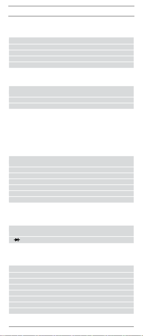
8.4 Diodenprüfung
- Mit dem Drehschalter die gewünschte Funktion ( ) am
BENNING MM 9/ 10 wählen.
- Die schwarze Sicherheitsmessleitung mit der COM-Buchse am
BENNING MM 9/ 10 kontaktieren.
- Die rote Sicherheitsmessleitung mit der Buchse für V, Ω, µA, , Hz am
BENNING MM 9/ 10 kontaktieren.
- Die Sicherheitsmessleitungen mit den Diodenanschlüssen kontaktieren, den
Mess wert an der Digitalanzeige am BENNING MM 9/ 10 ablesen.
- Für eine normale in Flussrichtung angelegte Si-Diode wird die Fluss span-
nung zwischen 0,400 V bis 0,900 V angezeigt. Die Anzeige „000„ deutet
auf einen Kurzschluss in der Diode hin, die Anzeige „OL“ deutet auf eine
Unter brechung in der Diode hin.
- Für eine in Sperrrichtung angelegte Diode wird „OL“ angezeigt. Ist die
Diode fehler haft, werden „000“ oder andere Werte angezeigt.
siehe Bild 7: Diodenprüfung
8.5 Durchgangsprüfung mit Summer
- Mit dem Drehschalter die gewünschte Funktion ( ) am
BENNING MM 9/ 10 wählen.
- Die schwarze Sicherheitsmessleitung mit der COM-Buchse am
BENNING MM 9/ 10 kontaktieren.
- Die rote Sicherheitsmessleitung mit der Buchse für V, Ω, µA, , Hz am
BENNING MM 9/ 10 kontaktieren.
- Die Sicherheitsmessleitungen mit den Messpunkten kontaktieren. Unter schreitet
der Leitungswiderstand zwischen der COM-Buchse und der Buchse für V, Ω,
µA, , Hz 100 Ω, ertönt im BENNING MM 9/ 10 der eingebaute Summer.
siehe Bild 8: Durchgangsprüfung mit Summer
8.6 Kapazitätsmessung
Kondensatoren vor Kapazitätsmessungen vollständig entladen!
Niemals Spannung an die Buchsen für Kapazitätsmessung anlegen!
Das Gerät kann beschädigt oder zerstört werden! Von einem
beschädigten Gerät kann eine elektrische Gefährdung ausgehen!
- Mit dem Drehschalter die gewünschte Funktion ( ) am
BENNING MM 9/ 10 wählen.
- Polarität des Kondensators ermitteln und Kondensator vollständig entladen.
- Die schwarze Sicherheitsmessleitung mit der COM-Buchse am
BENNING MM 9/ 10 kontaktieren.
- Die rote Sicherheitsmessleitung mit der Buchse für V, Ω, µA, , Hz am
BENNING MM 9/ 10 kontaktieren.
- Die Sicherheitsmessleitungen mit dem entladenen Kondensator entspre-
chend seiner Polarität kontaktieren, Messwert an der Digitalanzeige am
BENNING MM 9/ 10 ablesen.
siehe Bild 9: Kapazitätsmessung
8.7 Frequenzmessung
- Mit dem Drehschalter die gewünschte Funktion (Hz) am
BENNING MM 9/ 10 wählen.
- Die schwarze Sicherheitsmessleitung mit der COM-Buchse am
BENNING MM 9/ 10 kontaktieren.
- Die rote Sicherheitsmessleitung mit der Buchse für V, Ω, µA, , Hz
am BENNING MM 9/ 10 kontaktieren. Beachten Sie die minimale
Empfindlichkeit für Frequenzmessungen am BENNING MM 9/ 10!
- Die Sicherheitsmessleitungen mit den Messpunkten kontaktieren, den
Mess wert an der Digitalanzeige am BENNING MM 9/ 10 ablesen.
siehe Bild 10: Frequenzmessung
03/ 2011
BENNING MM 9/ 10
7
Page 15

D
9. Instandhaltung
Vor dem Öffnen das BENNING MM 9/ 10 unbedingt spannungs-
frei machen! Elektrische Gefahr!
Die Arbeit am geöffneten BENNING MM 9/ 10 unter Spannung ist ausschließ-
lich Elektrofachkräften vorbehalten, die dabei besondere Maßnahmen zur
Unfallverhütung treffen müssen.
So machen Sie das BENNING MM 9/ 10 spannungsfrei, bevor Sie das Gerät
öffnen:
- Entfernen Sie zuerst beide Sicherheitsmessleitungen vom Messobjekt.
- Entfernen Sie dann beide Sicherheitsmessleitungen vom
BENNING MM 9/ 10.
- Schalten Sie den Drehschalter in die Schaltstellung „OFF“.
9.1 Sicherstellen des Gerätes
Unter bestimmten Voraussetzungen kann die Sicherheit im Umgang mit dem
BENNING MM 9/ 10 nicht mehr gewährleistet sein; zum Beispiel bei:
- Sichtbaren Schäden am Gehäuse,
- Fehlern bei Messungen,
- Erkennbaren Folgen von längerer Lagerung unter unzulässigen
Bedingungen und
- Erkennbaren Folgen von außerordentlicher Transportbeanspruchung.
In diesen Fällen ist das BENNING MM 9/ 10 sofort abzuschalten, von den
Mess stellen zu entfernen und gegen erneute Nutzung zu sichern.
9.2 Reinigung
Reinigen Sie das Gehäuse äußerlich mit einem sauberen und trockenen Tuch
(Ausnahme spezielle Reinigungstücher). Verwenden Sie keine Lösungs- und/
oder Scheuermittel, um das Gerät zu reinigen. Achten Sie unbedingt darauf,
dass das Batteriefach und die Batteriekontakte nicht durch auslaufendes
Batterie-Elektrolyt verunreinigt werden.
Falls Elektrolytverunreinigungen oder weiße Ab lagerungen im Bereich der Batterie
oder des Batteriegehäuses vorhanden sind, reinigen Sie auch diese mit einem
trockenen Tuch.
9.3 Batteriewechsel
Vor dem Öffnen das BENNING MM 9/ 10 unbedingt spannungs-
frei machen! Elektrische Gefahr!
Das BENNING MM 9/ 10 wird durch eine eingebaute 9-V-Blockbatterie gespeist.
Ein Batteriewechsel (siehe Bild 11) ist erforderlich, wenn in der Anzeige das
Batteriesymbol erscheint.
So wechseln Sie die Batterie:
- Entfernen Sie die Sicherheitsmessleitungen vom Messkreis.
- Entfernen Sie die Sicherheitsmessleitungen vom BENNING MM 9/ 10.
- Bringen Sie den Drehschalter in die Schaltstellung „OFF“.
- Entfernen Sie den Gummi-Schutzrahmen vom BENNING MM 9/ 10.
- Legen Sie das BENNING MM 9/ 10 auf die Frontseite und lösen Sie die
beiden Schrauben vom Batteriedeckel.
- Heben Sie den Batteriedeckel (im Bereich der Gehäusevertiefungen) vom
Unterteil ab.
- Heben Sie die entladene Batterie aus dem Batteriefach und nehmen Sie die
Batteriezuleitungen vorsichtig von der Batterie ab.
- Die neue Batterie ist mit den Batteriezuleitungen zu verbinden, und ord-
nen Sie diese so, dass sie nicht zwischen den Gehäuseteilen gequetscht
werden. Legen Sie dann die Batterie an die dafür vorgesehene Stelle ins
Batteriefach.
- Rasten Sie den Batteriedeckel auf das Unterteil und ziehen Sie die
Schrauben an.
- Setzen Sie das BENNING MM 9/ 10 in den Gummi-Schutzrahmen ein.
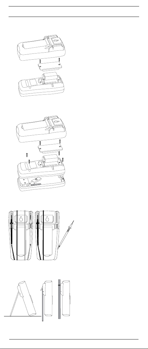
siehe Bild 11: Batteriewechsel
Leisten Sie Ihren Beitrag zum Umweltschutz! Batterien dürfen
nicht in den Hausmüll. Sie können bei einer Sammelstelle für
Altbatterien bzw. Sondermüll abgegeben werden. Informieren
Sie sich bitte bei Ihrer Kommune.
03/ 2011
BENNING MM 9/ 10
8
Page 16

D
9.4 Sicherungswechsel
Vor dem Öffnen das BENNING MM 9/ 10 unbedingt spannungs-
frei machen! Elektrische Gefahr!
Das BENNING MM 9/ 10 wird durch eine eingebaute Sicherung
(G-Schmelzeinsatz) 10 A vor Überlastung geschützt (siehe Bild 12)
So wechseln Sie die Sicherung:
- Entfernen Sie die Sicherheitsmessleitungen vom Messkreis.
- Entfernen Sie die Sicherheitsmessleitungen vom BENNING MM 9/ 10.
- Bringen Sie den Drehschalter in die Schaltstellung „OFF“.
- Entfernen Sie den Gummi-Schutzrahmen vom BENNING MM 9/ 10.
- Legen Sie das BENNING MM 9/ 10 auf die Frontseite und lösen Sie die vier
Schrauben vom Gehäuseboden.
Lösen Sie keine Schrauben an der gedruckten Schaltung des
BENNING MM 9/ 10!
- Heben Sie den Gehäuseboden im unteren Bereich an und nehmen Sie ihn
im oberen Bereich vom Frontteil ab.
- Heben Sie ein Ende der defekten Sicherung aus dem Sicherungshalter.
- Schieben Sie die defekte Sicherung vollständig aus dem Sicherungshalter.
- Setzen Sie die neue Sicherung mit gleichem Nennstrom, gleicher
Auslösecharakteristik und gleicher Abmessung ein.
- Ordnen Sie die neue Sicherung mittig in dem Halter an.
- Ordnen Sie die Batteriezuleitungen so, dass sie nicht zwischen den
Ge häuseteilen gequetscht werden.
- Rasten Sie den Gehäuseboden auf das Frontteil ein und montieren Sie die
vier Schrauben.
- Setzen Sie das BENNING MM 9/ 10 in den Gummi-Schutzrahmen ein.
siehe Bild 12: Sicherungswechsel
9.5 Kalibrierung
Um die angegebenen Genauigkeiten der Messergebnisse zu erhalten, muss
das Gerät regelmäßig durch unseren Werksservice kalibriert werden. Wir
empfehlen ein Kalibrierintervall von einem Jahr. Senden Sie hierzu das Gerät
an folgende Adresse:
Benning Elektrotechnik & Elektronik GmbH & Co. KG
Service Center
Robert-Bosch-Str. 20
D - 46397 Bocholt
9.6 Ersatzteile
Sicherung F 10 A, 500 V, 1,5 kA, D = 6,3 mm, L = 32 mm, TN 749726
10. Anwendung des Gummi-Schutzrahmens
- Sie können die Sicherheitsmessleitungen verwahren, indem Sie die
Sicherheitsmessleitungen um den Gummi-Schutzrahmen wickeln und
die Spitzen der Sicherheitsmessleitungen geschützt an den Gummi-Schutz-
rahmen einrasten (siehe Bild 13).
- Sie können eine Sicherheitsmessleitung so an den Gummi-Schutzrahmen
einrasten, dass die Messspitze freisteht, um die Messspitze gemeinsam
mit dem BENNING MM 9/ 10 an einen Messpunkt zu führen.
- Die rückwärtige Stütze am Gummi-Schutzrahmen ermöglicht, das
BENNING MM 9/ 10 schräg aufzustellen (erleichtert die Ablesung) oder
aufzuhängen (siehe Bild 14).
- Der Gummi-Schutzrahmen besitzt eine Öse, die für eine Auf hänge mög-
lich keit genutzt werden kann.
siehe Bild 13: Aufwicklung der Sicherheitsmessleitung
siehe Bild 14: Aufstellung des BENNING MM 9/ 10
11. Technische Daten des Messzubehörs
- Norm: EN 61010-031,
- Maximale Bemessungsspannung gegen Erde () und Messkategorie:
Mit Aufsteckkappe: 1000 V CAT III, 600 V CAT IV,
Ohne Aufsteckkappe: 1000 V CAT II,
- Maximaler Bemessungsstrom: 10 A,
- Schutzklasse II (), durchgängige doppelte oder verstärkte Isolierung,
- Verschmutzungsgrad: 2,
- Länge: 1,4 m, AWG 18,
- Umgebungsbedingungen:
Barometrische Höhe bei Messungen: Maximal 2000 m,
Temperatur: 0°C bis + 50 °C, Feuchte 50 % bis 80 %
03/ 2011
BENNING MM 9/ 10
9
Page 17

D
- Verwenden Sie die Messleitungen nur im einwandfreien und sauberen
Zustand sowie entsprechend dieser Anleitung, da ansonsten der vorgese-
hene Schutz beeinträchtigt sein kann.
- Sondern Sie die Messleitung aus, wenn die Isolierung beschädigt ist oder
eine Unterbrechung in Leitung/ Stecker vorliegt.
- Berühren Sie die Messleitung nicht an den blanken Kontaktspitzen. Fassen
Sie nur den Handbereich an!
- Stecken Sie die abgewinkelten Anschlüsse in das Messgerät.
12. Umweltschutz
Bitte führen Sie das Gerät am Ende seiner Lebensdauer den zur Verfügung ste hen den Rückgabe- und Sammelsystemen zu.
03/ 2011
BENNING MM 9/ 10
10
Page 18

Operating instructions
BENNING MM 9/ 10
Digital multimeter for
- Direct voltage measurements
- Alternating voltage measurements
- Direct current measurement
- Alternating current measurement
- Resistance measurement
- Diode test
- Continuity testing
- Capacity measurement
- Frequency measurement
Table of contents
1. User notes
2. Safety notes
3. Scope of delivery
4. Unit description
5. General information
6. Ambient conditions
7. Electrical specifications
8. Measuring with the BENNING MM 9/ 10
9. Maintenance
10. Application of rubber protection frame
11. Technical data of the measuring accessories
12. Environmental note
1. User notes
These operating instructions are intended for
- Skilled electricians and
- trained electronics personnel.
The BENNING MM 9/ 10 is intended for making measurements in dry environment. It must not be used in power circuits with a nominal voltage higher than
1000 V DC and 750 V AC (More details in Section 6. “Ambient conditions”
The following symbols are used in these operating instructions and on the
BENNING MM 9/ 10:
Warning of electrical danger!
Indicates instructions which must be followed to avoid danger to
persons.
Important, comply with the documentation!
The symbol indicates that the information provided in the operating
instructions must be complied with in order to avoid risks.
This symbol on the BENNING MM 9/ 10 means that the
BENNING MM 9/ 10 is totally insulated (protection class II).
This symbol on the BENNING MM 9/ 10 indicates the built in fuses.
This symbol appears in the display to indicate a discharged battery.
This symbol designates the „diode test” range.
This symbol designates the „continuity test” range.
The buzzer is used for the acoustic result output.
This symbol designates the „capacity test” range.
(DC) Direct voltage or current.
(AC) Alternating voltage or current.
Ground (Voltage against ground).
03/ 2011
BENNING MM 9/ 10
11
Page 19

2. Safety notes
The instrument is built, tested and approved in accordance with
DIN VDE 0411 part 1/ EN 61010-1
and has left the factory in perfectly safe technical state.
To maintain this state and ensure safe operation of the appliance tester, the user
must observe the notes and warnings given in these instructions at all times.
The unit may be used only in power circuits within the
overvoltage category III with a conductor for 1000 V max. to
earth, or within overvoltage category IV with a conductor for
600 V against ground.
Only use suitable measuring leads for this. With measurements
within measurement category III or measurement category IV,
the projecting conductive part of a contact tip of the measuring
leads must not be longer than 4 mm.
Prior to carrying out measurements within measurement
category III and measurement category IV, the pushon caps
provided with the set and marked with CAT III and CAT IV must
be pushed onto the contact tips. The purpose of this measure
is user protection.
Remember that work on electrical components of all kinds is
dangerous. Even low voltages of 30 V AC and 60 V DC may be
dangerous to human life.
Before starting the multimeter, always check it as well as all
measuring leads and wires for signs of damage.
Should it appear that safe operation of the appliance tester is no longer possible,
it should be shut down immediately and secured to prevent it being switched
on accidentally.
It may be assumed that safe operation is no longer possible:
- if the instrument or the measuring leads show visible signs of damage, or
- if the multimeter no longer functions, or
- after long periods of storage under unfavourable conditions, or
- after being subjected to rough transport.
In order to avoid danger,
- do not touch the bare prod tips of the measuring leads
- insert the measurement leads in the appropriately designated measuring sockets on the multimeter
3. Scope of delivery
The scope of delivery for the BENNING MM 9/ 10 comprises:
3.1 One BENNING MM 9/ 10,
3.2 One item software PC-Win MM 10 (BENNING MM 10)
3.3 One serial data cable with USB 2.0 compatible connection
(BENNING MM 10)
3.4 One safety measuring lead, red (L = 1.4 m)
3.5
One safety measuring lead, black (L = 1.4 m)
3.6 One rubber protection frame,
3.7 One compact protective pouch
3.8 The unit is fitted with a 9-V block battery and a fuse as original equipment,
3.9
One operating instructions manual
Parts subject to wear:
- The BENNING MM 9/ 10 contains a fuse as protection against overload:
One item of a fuse with a rated current 10 A, quick-acting, (500 V),
D = 6.35 mm, L = 32 mm (part no. 749726)
-
The BENNING MM 9/ 10 is supplied by a fitted 9V block battery (IEC 6 LR 61) .
- The above-mentioned safety measuring leads (tested accessories) cor-
respond to CAT III 1000 V and are approved for a current of 10 A.
4. Unit description
See Fig. 1a, 1b: Appliance front face
The display and operating elements shown in Figs. 1a and 1b are designated
as follows:
Digital display, for the measuring value and indication of overranging,
The polarity indication,
Battery indication, appears when the battery is discharged,
03/ 2011
BENNING MM 9/ 10
12
Page 20

MIN/MAX button, storing the highest and lowest measured value
RS-232 button, activation of the optical interface for transmitting the mea-
sured values ( BENNING MM 10),
RANGE button, switchover automatic/ manual measuring range,
HOLD button, storing the indicated measured value,
Button (yellow), display lighting ( BENNING MM 10),
Rotary switch, for selecting the measuring function,
Jack (positive1), for V, Ω, µA, , Hz
COM jack for current, voltage, resistance, frequency, capacity measure-
ments, continuity and diode testing,
Jack (positive1), for A range, for currents up to 10 A,
Rubber protection frame
Optical interface, for accommodating the adapter located on the data
cable ( BENNING MM 10),
1) This is what the automatic polarity indication for direct current and voltage refers to.
5. General information
5.1 General details on the multimeter
5.1.1 The digital display for the test voltage is a 4-digit liquid crystal display
with 16 mm high numerals. The largest numerical value which can be
displayed is 6000.
5.1.2 The polarity indication is automatic. Only one polarity with respect to
the socket marked “-” is indicated.
5.1.3 The overranging is indicated by “OL” or “-OL” and, in part, an acoustic
warning.
Warning, no indication and prior warning in the event of an overload
condition!
5.1.4 The MIN/MAX button function inputs and stores automatically the
highest and lowest measured value. The following values are indicated
by button operation:
“MAX” indicates the stored maximum value, and “MIN” indicates the
lowest value. The continuous detection of the MAX-/ MIN value can
be stopped or started by pressing the button “HOLD” . Pressing the
button “MIN/MAX” for an extended period of time (2 seconds) switches
back into normal mode.
5.1.5 The RS-232 button activates the optical infrared interface for transmitting the measured values from the BENNING MM 10 to a PC/ laptop. The PC/ laptop is galvanically separated from the measuring signal
by means of the optical infrared interface. The activation is effected with
the simultaneous display of “RS232” in the display unit.
5.1.6 The button “RANGE” is used to index the manual measuring ranges
whilst simultaneously fading out “AUTO” in the display. Press the button for an extended period (2 seconds) to select the automatic range
selection (indication “AUTO”):
5.1.7 Measured value storage “HOLD”: Press the button “HOLD” to store
the measured result. At the same time, the display shows the symbol
“HOLD. A renewed press of the button switches back into measuring
mode.
5.1.8 Button (yellow) switches on the display illumination. Press button
again to switch off.
5.1.9 The measuring rate of the BENNING MM 9/ 10 amounts nominally to
1.5 measurements per second for the digital display.
5.1.10 The BENNING MM 9/ 10 is switched on or off by the rotary switch .
Shutdown position “OFF”.
5.1.11 The BENNING MM 9/ 10 switches off automatically after approx. 10
minutes (APO, Auto Power Off). It switches back on again if a button
or the rotary switch is operated. A buzzer sound signals the automatic
shutdown of the unit. The shutdown is not active, if the RS-232 button
is first operated.
5.1.12 Temperature coefficient of the measured value: 0.15 x (stated measuring precision)/ °C < 18 °C or > 28 °C, related to the value for the reference temperature of 23 °C.
5.1.13
The BENNING MM 9/ 10 is supplied by a fitted 9 V block battery
(IEC 6 LR 61).
5.1.14 If the battery voltage drops below the specified operating voltage of the
BENNING MM 9/ 10, then a battery symbol appears in the display .
5.1.15 The life span of a battery amounts to approx. 300 hours (alkali battery).
5.1.16 Appliance dimensions:
(L x W x H) = 158 x 76 x 38 mm without rubber protection frame
(L x W x H) = 164 x 82 x 44 mm with rubber protection frame
Appliance weight:
265 g without rubber protection frame
365 g with rubber protection frame
03/ 2011
BENNING MM 9/ 10
13
Page 21

5.1.17
The safety measuring leads supplied are expressly suited for the rated
voltage and the rated current of the BENNING MM 9/ 10.
5.1.18 The BENNING MM 9/ 10 is protected by a rubber protection frame
against mechanical damage. The rubber protection frame allows the
BENNING MM 9/ 10 to be set up or hung up during the measurement.
5.1.19 The BENNING MM 10 features at its head an optical interface . This
is used for the galvanic separation of the measuring signal to a PC/ laptop. The enclosed data cable is used for the transmission of measuring
data and is equipped with a USB 2.0 compatible connection.
6. Ambient conditions
- The BENNING MM 9/ 10 is intended for making measurements in dry envi-
ronment.
- Maximum barometric elevation for making measurements: 2000 m,
- Overvoltage category/ Siting category: IEC 60664-1/ IEC 61010-1 → 600 V
category IV; 1000 V category III,
- Contamination class: 2,
- Protection Class: IP 30 (DIN VDE 0470-1 IEC/ EN 60529)
IP 30 means: Protection against access to dangerous parts and protection
against solid impurities of a diameter > 2.5 mm, (3 - rst index). No protection against water, (0 - second index).
- Operating temperature and relative humidity:
For operating temperature from 0 °C to 30 °C: relative humidity less than 80 %
For operating temperature from 31 °C to 40 °C: relative humidity less than 75 %
For operating temperature from 41 °C to 50 °C: relative humidity less than 45 %
- Storage temperature: The BENNING MM 9/ 10 can be stored at any tem-
perature in the range from - 20 °C to + 60 °C (relative humidity from 0 to 80
%). The battery should be taken out of the instrument for storage.
7. Electrical specifications
Note: The measuring precision is specified as the sum of
- a relative fraction of the measured value and
- a number of digits (counting steps of the least significant digit).
This specified measuring precision is valid for temperatures in the range from
18 °C to 28 °C and relative humidity less than 80 %.
7.1 Direct voltage ranges
The input resistance amounts to 10 MΩ (within the 400 mV range 1 GΩ).
Measuring
range
Resolution Meas. precision
600 mV 100 µV ± (0.5 % of the measured value + 2 digits) 1000 V
6 V 1 mV ± (0.5 % of the measured value + 2 digits) 1000 V
60 V 10 mV ± (0.5 % of the measured value + 2 digits) 1000 V
600 V 100 mV ± (0.5 % of the measured value + 2 digits) 1000 V
1000 V 1 V ± (0.5 % of the measured value + 2 digits) 1000 V
7.2 Alternating voltage ranges
The input resistance amounts to 10 MΩ parallel 100 pF.
Measuring
range
Resolution
600 mV 100 µV
6 V 1 mV
60 V 10 mV
600 V 100 mV
750 V 1 V
The measured value of the BENNING MM 9/ 10 is obtained as a real effective
value (TRUE RMS) and then displayed.
*1
The measuring accuracy is specified for sinusoidal curves and is valid for
indicating values below 4000 digits. For indicating values higher than 4000
digits 0.6 % have to be added to the specified measuring accuracy. In case
of non-sinusoidal curves below 2000 digits, the indicating value becomes
inaccurate. Thus, an additional error occurs for the following crest factors:
crest factor from 1.4 to 3.0 additional error ± 1.5 %
*2
valid for sinusoidal curves 50 Hz/ 60 Hz
Meas. precision*1 within the frequency
range 50 Hz - 500 Hz
± (0.9 % of the measured value + 5 digits) *2750 V
± (0.9 % of the measured value + 5 digits) *2750 V
± (0.9 % of the measured value + 5 digits) *2750 V
± (0.9 % of the measured value + 5 digits) *2750 V
± (0.9 % of the measured value + 5 digits) *2750 V
Overload
protection
Overload
protection
DC
DC
DC
DC
DC
eff
eff
eff
eff
eff
03/ 2011
BENNING MM 9/ 10
14
Page 22
7.3 Direct current ranges
overload protection:
- 600 V
at the µA input,
eff
- 10 A (500 V) fuse, quick-acting, at the 10 A input,
Measuring
6000 µA 1 µA
7.4 Alternating current ranges
overload protection:
- 10 A (500 V) fuse, quick-acting, at the 10 A input,
Measuring
The measured value of the BENNING MM 9/ 10 is obtained as a real effective
value (TRUE RMS) and then displayed.
*1
crest factor from 1.4 to 3.0 additional error ± 1.5 %
7.5 Resistance measuring ranges
Overload protection in the case of resistance measurements: 600 V
Measuring
Resolution Meas. precision Voltage drop
range
600 µA 0,1 µA
6 A 1 mA
10 A 10 mA
Resolution
range
6 A 1 mA
10 A 10 mA
The measuring accuracy is specified for sinusoidal curves and is valid for
indicating values below 4000 digits. For indicating values higher than 4000
digits 0.6 % have to be added to the specified measuring accuracy. In case
of non-sinusoidal curves below 2000 digits, the indicating value becomes
inaccurate. Thus, an additional error occurs for the following crest factors:
Resolution Meas. precision
range
600 Ω 0,1 Ω
6 kΩ 1 Ω
60 kΩ 10 Ω
600 kΩ 100 Ω
6 MΩ 1 kΩ
60 MΩ 10 kΩ
± (1.0 % of the measured value + 2 digits)
± (1.0 % of the measured value + 2 digits)
± (1.0 % of the measured value + 2 digits)
± (1.0 % of the measured value + 2 digits)
Meas. precision*1 within the
frequency range 50 Hz - 500 Hz
± (1.5 % of the measured value + 5 digits)
± (1.5 % of the measured value + 5 digits)
± (0.7 % of the measured value + 2 digits)
± (0.7 % of the measured value + 2 digits)
± (0.7 % of the measured value + 2 digits)
± (0.7 % of the measured value + 2 digits)
± (0.7 % of the measured value + 2 digits)
± (0.7 % of the measured value + 2 digits)
< 4 mV/ µA
< 4 mV/ µA
2 V max.
2 V max.
Voltage drop
2 V max.
2 V max.
eff
Max. idling
voltage
1,3 V
1,3 V
1,3 V
1,3 V
1,3 V
1,3 V
7.6 Diode and continuity testing
The indicated measurement precision applies in the range between 0.4 V and 0.8 V.
Overload protection for diode testing: 600 V
The built-in buzzer sounds in the case of a resistance R less than 100 Ω.
Meas.
resolu-
range
tion
10 mV
7.7 Capacity ranges
Conditions:
Overload protection for capacity measurements: 600 V
Discharge capacitors and apply according to the specified polarity.
Meas. precision
± (1.5 % of the measured value + 5 digit)
eff
Max. meas.
current
Max. idling
voltage
1,5 mA 3,0 V
eff
Measuring range Resolution Meas. precision
6 nF 1 pF ± (1.9 % of the measured value + 8 digits)
60 nF 10 pF ± (1.9 % of the measured value + 8 digits)
600 nF 100 pF ± (1.9 % of the measured value + 8 digits)
6 µF 1 nF ± (1.9 % of the measured value + 8 digits)
60 µF 10 nF ± (1.9 % of the measured value + 8 digits)
600 µF 100 nF ± (1.9 % of the measured value + 8 digits)
6 mF 1 µF ± (1.9 % of the measured value + 8 digits)
03/ 2011
BENNING MM 9/ 10
15
Page 23
7.8 Frequency ranges
Overload protection in the case of frequency measurements: 600 V
Meas.
resolution Meas. precision for 5 V
range
eff
max.
6 kHz 1 Hz ± (0.01 % of the measuring value + 1 digit) 100 mV
60 kHz 10 Hz ± (0.01 % of the measuring value + 1 digit) 100 mV
600 kHz 100 Hz ± (0.01 % of the measuring value + 1 digit) 100 mV
6 MHz 1 kHz ± (0.01 % of the measuring value + 1 digit) 250 mV
60 MHz 10 kHz ± (0.01 % of the measuring value + 1 digit) 1 V
The minimum sensitivity for frequencies below 20 Hz is 1.5 V
8. Measuring with the BENNING MM 9/ 10
8.1 Preparations for measuring
Operate and store the BENNING MM 9/ 10 only at the specified storage and
operating temperatures conditions. Avoid continuous insulation.
- Check rated voltage and rated current details specified on the safety mea-
suring leads. The nominal voltage and current ratings of the safety measuring leads included in the scope of delivery correspond to the ratings of the
BENNING MM 9/ 10.
- Check the insulation of the safety measuring leads. Discard the safety
measuring leads immediately if the insulation is damaged.
- Check safety measuring leads for continuity. If the conductor in the safety
measuring lead is interrupted, the safety measuring lead must be quarantined immediately.
- Before at the rotary switch a different function is selected, the safety
measuring leads must be disconnected from the measuring point.
- Strong sources of interference in the vicinity of the BENNING MM 9/ 10 can
lead to unstable readings and measuring errors.
8.2 Voltage and current measurement
Do not exceed the maximum permitted voltage with respect to
earth potential! Electrical danger!
The highest voltage which may be applied to the jacks,
- COM jack
- jack for V, Ω, µA, , Hz
- jack for 10 A range
of the BENNING MM 9/ 10 against ground, amounts to 1000 V.
Electrical danger!
Maximum circuit voltage for a measured current of 500 V! In
the case of a safety triggering in excess of 500 V, damage to the
appliance may be caused. A damaged appliance may represent
an electrical hazard!
eff
Min.
sensitivity
eff
eff
eff
eff
eff
.
eff
8.2.1 Voltage measuring
- Using the rotary switch select the required function (V AC) or (V DC) on
the BENNING MM 9/ 10.
- The black safety measuring lead has to be connected to the COM jack
on the BENNING MM 9/ 10.
- The red safety measuring lead has to be connected to the jack for V, Ω, µA,
, Hz on the BENNING MM 9/ 10.
- Bring the safety measuring leads into contact with the measuring points, read
the measured value on the digital display on the BENNING MM 9/ 10.
see figure 2: Direct voltage measurement
see figure 3: Alternating voltage measurement
8.2.2 Current measuring
- Using the rotary switch select the required range and function (A AC) or
(A DC) on BENNING MM 9/ 10.
- The black safety measuring lead has to be connected to the COM jack
on the BENNING MM 9/ 10.
- The red safety measuring lead has to be connected to the jack for V, Ω, µA,
, Hz (direct currents on the 6 mA) or to the jack for the 10 A range
(direct or alternating currents up to 10 A) on the BENNING MM 9/ 10.
- Bring the safety measuring leads into contact with the measuring points, read
the measured value on the digital display on the BENNING MM 9/ 10.
see figure 4: Direct current measurement
see figure 5: Alternating current measurement
03/ 2011
BENNING MM 9/ 10
16
Page 24
8.3 Resistance measurements
- Using the rotary switch select the required function (Ω) on the
BENNING MM 9/ 10.
- The black safety measuring lead has to be connected to the COM jack
on the BENNING MM 9/ 10.
- The red safety measuring lead has to be connected to the jack for V, Ω, µA,
, Hz on the BENNING MM 9/ 10.
- Bring the safety measuring leads into contact with the measuring points, read
the measured value on the digital display on the BENNING MM 9/ 10.
see figure 6: Resistance measurements
8.4 Diode test
- Using the rotary switch select the required function ( ) on the
BENNING MM 9/ 10.
- The black safety measuring lead has to be connected to the COM jack
on the BENNING MM 9/ 10.
- The red safety measuring leads has to be connected to the jack for V, Ω,
µA, , Hz on the BENNING MM 9/ 10.
- Bring the safety measuring lead into contact with the diode connections, read
the measured value on the digital display on the BENNING MM 9/ 10.
- For a standard Si diode applied in conduction direction the conduction volt-
age between 0.400 V to 0.900 V is displayed. The display “000” indicates a
short circuit in the diode, display values “OL” indicate an interruption in the
diode.
- For a diode applied in reverse direction “OL” is displayed. If the diode is
defective, “000” or other values are shown.
see figure 7: Diode test
8.5 Continuity testing with buzzer
- Using the rotary switch select the required function ( ) on the
BENNING MM 9/ 10.
- The black safety measuring lead has to be connected to the COM jack
on the BENNING MM 9/ 10.
- The red safety measuring lead has to be connected to the jack for V, Ω, µA,
, Hz on the BENNING MM 9/ 10.
- The safety measuring leads have to be brought into contact with the mea-
suring points. If the line resistance between the COM jack and the jack
for V, Ω, µA, , Hz is below 100 Ω, the fitted buzzer sounds on the
BENNING MM 9/ 10.
see figure 8: Continuity testing with buzzer
8.6 Capacity measurement
Before carrying out capacity measurements discharge
capacitors completely!
Never apply voltage to the capacity measurement jacks!
The appliance can become damaged or even be destroyed! A
damaged appliance may cause an electrical hazard!
- Using the rotary switch select the required function ( ) on the
BENNING MM 9/ 10.
- Determine the polarity of the capacitor and discharge capacitor completely.
- The black safety measuring lead has to be connected to the COM jack
on the BENNING MM 9/ 10.
- The red safety measuring lead has to be connected to the jack for V, Ω, µA,
, Hz on the BENNING MM 9/ 10.
- The safety measuring leads have to be brought into contact with the dis-
charged capacitor according to its polarity, read the measured value on the
digital display on the BENNING MM 9/ 10.
see figure 9: capacity measuring
8.7 Frequency measuring
- Using the rotary switch select the required function (Hz) on the
BENNING MM 9/ 10.
- The black safety measuring lead has to be connected to the COM jack
on the BENNING MM 9/ 10.
- The red safety measuring lead has to be connected to the jack for V, Ω, µA,
, Hz on the BENNING MM 9/ 10.
Note the minimum sensitivity for the frequency measurements on the
BENNING MM 9/ 10!
- Bring the safety measuring leads into contact with the measuring points, read
the measured value on the digital display on the BENNING MM 9/ 10.
see figure 10: Frequency measurement
03/ 2011
BENNING MM 9/ 10
17
Page 25

9. Maintenance
Before opening the BENNING MM 9/ 10 make sure that it is free
of voltage! Electrical danger!
Work on the opened BENNING MM 9/ 10 under voltage may be carried out
only by skilled electricians with special precautions for the prevention
of accidents.
Make the BENNING MM 9/ 10 voltage free as follows before opening the
instrument:
- First remove the two safety measuring leads from the object to be mea-
sured.
- Then disconnect the two safety measuring leads from the BENNING MM 9/ 10.
- Turn the rotary switch to the switch setting ”OFF”.
9.1 Securing the instrument
Under certain circumstances safe operation of the BENNING MM 9/ 10 is no
longer ensured, for example in the case of:
- Visible damage of the casing.
- Incorrect measurement results.
- Recognisable consequences of prolonged storage under improper condi-
tions.
- Recognisable consequences of extraordinary transportation stress.
In such cases the BENNING MM 9/ 10 must be switched off immediately, disconnected from the measuring points and secured to prevent further utilisation.
9.2 Cleaning
Clean the casing externally with a clean dry cloth (exception: special cleaning
wipers). Avoid using solvents and/ or scouring agents for cleaning the instrument. It is important to make sure that the battery compartment and battery
contacts are not contaminated by leaking electrolyte.
If electrolyte contamination or white deposits are present in the region of the
batteries or battery casing, clean them too with a dry cloth.
9.3 Battery change
Before opening the BENNING MM 9/ 10 make sure that it is free
of voltage! Electrical danger!
The BENNING MM 9/ 10 is supplied by a fitted 9 V block battery.
A battery change (see Figure 11) is required, if in the display the battery
symbol appears.
Proceed as follows to replace the batteries:
- Disconnect the safety measuring leads from the measuring circuit.
- Disconnect the two safety measuring leads from the BENNING MM 9/ 10.
- Turn the rotary switch to the switch setting ”OFF”.
- Remove the rubber protection frame M from the BENNING MM 9/ 10.
- Lay the BENNING MM 9/ 10 face down and release the two slot screws of
the battery compartment cover.
- Lift the battery compartment lid (in the housing recess area) from the bottom
section.
- Lift the discharged battery from the battery compartment and carefully
disconnect the battery supply lines from the battery.
- The new battery has to be connected to the battery supply lines, and
arrange these such that they are not crushed between the housing parts.
Place the battery/batteries into the battery compartment provided for this
purpose.
- Place the battery compartment cover onto the bottom part and tighten the
screws.
- Insert the BENNING MM 9/ 10 into the rubber protection frame .
see figure 11: Battery change
Make your contribution to environmental protection! Do not
dispose of discharged batteries in the household garbage.
Instead, take them to a collecting point for discharged
batteries and special waste material. Please inform yourself
in your community.
03/ 2011
BENNING MM 9/ 10
18
Page 26

9.4 Fuse replacement
Before opening the BENNING MM 9/ 10 make sure that it is
free of voltage! Electrical danger!
The BENNING MM 9/ 10 is protected against overload conditions by means of
a fitted fuse (G melt insert) 10 A (see Figure 12)
Proceed as follows to replace the fuse:
- Disconnect the safety measuring leads from the measuring circuit.
- Disconnect the safety measuring leads from the BENNING MM 9/10/.
- Turn the rotary switch to the switch setting ”OFF”.
- Remove the rubber protection frame from the BENNING MM 9/ 10.
- Lay the BENNING MM 9/ 10 face down and release the four slot screws of
the housing bottom.
Do not undo any screws on the printed circuit of the
BENNING MM 9/ 10!
- Lift up the housing bottom in the lower section and remove the same at the
top from the front section.
- Lift one end of the defective fuse from the fuse holder.
- Fully push the defective fuse out of the fuse holder.
- Insert a new fuse which has the same current rating, disconnecting charac-
teristic and dimensions.
- Make sure that the new fuse is seated centred in the holder.
- Order the battery supply lines such that they are not crushed between the
housing parts.
- Engage the front end on the housing bottom and fit the three screws.
- Insert the BENNING MM 9/ 10 into the rubber protection frame .
see figure 12: Fuse replacement
9.5 Calibration
To maintain the specified accuracy of the measurement results, the instrument
must be recalibrated at regular intervals by our factory service. We recommend
a recalibration interval of one year. Send the appliance to the following address:
Benning Elektrotechnik & Elektronik GmbH & CO. KG
Service Centre
Robert-Bosch-Str. 20
D - 46397 Bocholt
9.6 Spare parts
Fuse F 10 A, 500 V, 1.5 kA, D = 6.3 mm, L = 32 mm part no. 749726
10. Application of rubber protection frame
- You can store the safety measuring leads by winding the safety measuring
leads around the rubber protection frame and engaging the tips of the
safety measuring leads with protection against the rubber protection frame
(see figure 13).
- You can engage a safety measuring lead to the rubber protection frame
, that the measuring tip protrudes freely, in order to be able to apply the
measuring tip - jointly with the BENNING MM 9/ 10 to a measuring point.
- The rear support on the rubber protection frame provides for an inclined
setup of the BENNING MM 9/ 10 (facilitates reading) or attachment (see
Figure 14).
The rubber protection frame is fitted with a lug which can be freely used
for an attachment option.
see figure 13: Winding up of the safety measurement leads
see figure 14: Erecting the BENNING MM 9/ 10
11. Technical data of the measuring accessories
- Standard: EN 61010-031,
- Maximum rated voltage to earth () and measuring category:
With push-on caps: 1000 V CAT III, 600 V CAT IV,
Without push-on caps: 1000 V CAT II,
- Maximum rated current: 10 A,
- Protective class II (), continuous double or reinforced insulation,
- Contamination class: 2,
- Length: 1.4 m, AWG 18,
- Environmental conditions:
Maximum barometric elevation for making measurements: 2000 m,
Temperatures: 0 °C to + 50 °C, humidity 50 % to 80 %
- Only use the measuring leads if in perfect and clean condition as well as
according to this manual, since the protection provided could otherwise be
03/ 2011
BENNING MM 9/ 10
19
Page 27

impaired.
- Throw the measuring lead out if the insulation is damaged or if there is a
break in the lead/ plug.
- Do not touch the bare contact tips of the measuring lead. Only grab the area
appropriate for hands!
- Insert the angled terminals in the measuring device.
12. Environmental note
At the end of the product’s useful life, please dispose of the device at
collection points provided in your community.
03/ 2011
BENNING MM 9/ 10
20
Page 28

F
Notice d’emploi
BENNING MM 9/ 10
Multimètre numérique pour
- mesure de tension continue
- mesure de tension alternative
- mesure de courant continu
- mesure de courant alternatif
- mesure de résistance
- contrôle de diodes
- contrôle de continuité
- mesure de capacité
- mesure de fréquence
Sommaire
1. Remarques à l’attention de l’utilisateur
2. Consignes de sécurité
3. Fourniture
4. Description de l’appareil
5. Indications générales
6. Conditions d’environnement
7. Indication des valeurs électriques
8. Mesure avec le BENNING MM 9/ 10
9. Entretien
10. Utilisation du cadre de protection en caoutchouc
11. Données techniques des accessoires de mesure
12. Information sur l’environnement
1. Remarques à l’attention de l’utilisateur
Cette notice d’emploi s’adresse aux
- électrotechniciens et
- personnes instruites dans le domaine électrotechnique
Le BENNING MM 9/ 10 est conçu pour effectuer des mesures dans un environnement sec. Il ne doit pas être utilisé dans des circuits dont la tension nominale
est supérieure à 1000 V CC et à 750 V CA (pour de plus amples informations,
consulter la section 6 « Conditions d’environnement ».
Les symboles suivants sont utilisés dans cette notice d’emploi et sur le
BENNING MM 9/ 10:
Attention ! Danger électrique !
Se trouve devant les remarques devant être respectées afin d‘éviter
tout risque pour les personnes.
Attention ! Se conformer à la documentation !
Ce symbole indique qu‘il faut tenir compte des remarques contenues
dans cette notice d‘emploi pour éviter les risques.
Ce symbole sur le BENNING MM 9/ 10 signifie que le
BENNING MM 9/ 10 est doté d‘une isolation double (classe de
protection II.
Ce symbole sur le BENNING MM 9/ 10 fait référence aux fusibles
incorporés.
Ce symbole apparaît sur l‘affichage indiquant que la batterie est
déchargée.
Ce symbole caractérise la gamme « Contrôle de diodes ».
Ce symbole caractérise la gamme « Contrôle de continuité ».
Le ronfleur fournit un résultat acoustique.
Ce symbole caractérise la gamme « Contrôle de capacité ».
(CC) Tension continue ou courant continu.
(CA) Tension alternative ou courant alternatif.
Terre (tension à la terre).
03/ 2011
BENNING MM 9/ 10
21
Page 29

F
2. Consignes de sécurité
Cet appareil a été fabriqué et contrôlé conformément à
DIN VDE 0411 Partie 1/ EN 61010-1
et a quitté les ateliers de production dans un état technique parfait.
Pour conserver cet état et garantir un service sans risques, l’utilisateur doit se
conformer aux remarques et aux avertissements contenus dans cette notice
d’utilisation.
L‘appareil doit être utilisé uniquement dans des circuits
électriques de la catégorie de protection contre les surtensions
III avec un conducteur de 1000 V au max. raccordé à la terre ou
de la catégorie de protection contre les surtensions IV avec un
conducteur de 600 V au max. raccordé à la terre.
Utiliser uniquement des câbles de mesure approprié pour cela.
Pour les mesures au sein de la catégorie de mesure III ou de
la catégorie de mesure IV, la partie conductrice saillante doit
avoir une pointe de contact sur les câbles de mesure pas plus
longue que 4 mm.
Avant les mesures au sein de la catégorie de mesure III et de la
catégorie de mesure IV, les capuchons joints au kit et signalés
par CAT III et CAT IV doivent être placés sur les pointes de
contact. Cette mesure est pour protéger l’utilisateur.
Veuillez noter que les travaux au niveau d‘éléments et
d‘installations conducteurs de tension sont toujours
dangereux. Déjà les tensions de 30 V CA et 60 V CC peuvent
être mortelles.
Assurezvous, avant chaque mise en marche, que l‘appareil et
les câbles ne sont pas détériorés.
Si l’on considère que l’utilisation sans risques n’est plus possible, il faut mettre
l’appareil hors service et le protéger contre toute utilisation involontaire.
Une utilisation sans risques n’est plus possible
- quand l’appareil ou les câbles de mesure présentent des détériorations
visibles,
- quand l’appareil ne fonctionne plus,
- après un stockage prolongé dans de mauvaises conditions,
- après des conditions difficiles de transport.
Pour exclure tout danger,
ne touchez pas les parties dénudées des câbles de mesure
au niveau des pointes de mesure,
raccordez les câbles de mesure aux douilles de mesure
repérées correspondantes du multimètre
3. Fourniture
Font partie de la fourniture du BENNING MM 9/ 10 :
3.1 un BENNING MM 9/ 10,
3.2 un logiciel PC-Win MM 10 ( BENNING MM 10)
3.3 un câble de données sériel avec un adaptateur compatible à USB 2.0
(BENNING MM 10)
3.4 un câble de mesure de sécurité, rouge (L = 1,4 m),
3.5 un câble de mesure de sécurité, noir (L = 1,4 m),
3.6 un cadre de protection en caoutchouc,
3.7 un étui compact de protection,
3.8 une pile monobloc de 9 V et un fusible sont montés initialement dans
l’appareil,
3.9
une notice d’emploi.
Remarque concernant les pièces d’usure :
- Le BENNING MM 9/ 10 comporte un fusible de protection contre les sur-
charges :
un fusible pour courant nominal de 10 A à action instantanée (500 V),
D = 6,35 mm, L = 32 mm (Réf 749726)
- Le BENNING MM 9/ 10 est alimenté par une pile monobloc incorporée de
9 V (IEC 6 LR 61).
- Les câbles de mesure de sécurité (accessoires contrôlés) mentionnés ci-
dessus correspondent à CAT III 1000 V et sont homologués pour un courant
de 10 A.
03/ 2011
BENNING MM 9/ 10
22
Page 30

F
4. Description de l’appareil
voir fig. 1a, 1b : Partie avant de l’appareil
Les éléments d’affichage et de commande mentionnés aux figures 1a et 1b
portent les désignations suivantes :
indicateur numérique pour la valeur mesurée et l’afchage de dépasse-
ment de gamme,
afchage de polarité,
indicateur de piles, apparaît quand le pile est déchargée,
touche MIN/ MAX, mémorisation de la valeur mesurée maximum et mini-
mum,
touche RS-232, activation de l’interface optique pour le transfert des va-
leurs mesurées ( BENNING MM 10),
touche RANGE, commutation automatique/manuelle de la gamme de me-
sure,
Touche HOLD, mémorisation de la valeur mesurée afchée,
touche (jaune), éclairage de visualisation ( BENNING MM 10),
commutateur rotatif, pour la sélection de la fonction de mesure,
douille (positive1), pour V, Ω, µA, , Hz,
douille COM, douille commune pour mesures de courant, de tension, de
résistance, de fréquence, de capacité, contrôle de continuité et de diodes,
douille (positive1), pour gamme de A, pour courants jusqu’à 10 A,
cadre de protection en caoutchouc
interface optique, afin de connecter l‘adaptateur situé au câble de don-
nées (BENNING MM 10)
1) L’afchage automatique de polarité du courant continu et de la tension continue se rap-
porte à cela.
5. Indications générales
5.1 Indications générales concernant le multimètre
5.1.1 L’indicateur numérique est un indicateur ACL à 4 positions d’une
hauteur de caractères de 16 mm et à virgule décimale. La plus grande
valeur affichée est 6000.
5.1.2 L’affichage de la polarité a lieu automatiquement. Seule une polarité
contre la définition des douilles est indiquée par « - ».
5.1.3 Le dépassement de plage est indiquée par « 0L » ou « -0L » et, partiel-
lement, par un signal acoustique.
Attention: pas d’affichage et d’avertissement en cas de surcharge !
5.1.4 La touche de fonction MIN/MAX saisit et mémorise automatique-
ment la valeur mesurée maximum et minimum. Les valeurs suivantes
sont affichées quand on actionne la touche :
« MAX » affiche la valeur maximum mémorisée et « MIN » la valeur
minimum mémorisée. On peut interrompre ou lancer la saisie continue
de la valeur MAX/MIN à l’aide de la touche « HOLD » . Quand on
exerce une pression prolongée (2 secondes) sur la touche « MIN/
MAX », on retourne au mode normal.
5.1.5 La touche RS-232 active l’interface optique IR pour le transfert
des valeurs mesurées du BENNING MM 10 vers un micro-ordinateur/
ordinateur portatif. Le micro-ordinateur/ordinateur portatif est isolé électriquement du signal de mesure par l’interface optique IR. L’activation a
lieu en même temps que l’affichage de « RS232 » sur la visualisation.
5.1.6 La touche de plage « RANGE » sert à changer de gamme de
mesure manuelle sans que n’apparaisse « AUTO » sur la visualisation.
En cas de pression prolongée (2 secondes), la sélection automatique
de gamme de mesure est activée (affichage « AUTO »).
5.1.7 Mémorisation des valeurs mesurées « HOLD » : On peut mémoriser le
résultat de la mesure en actionnant la touche « HOLD » . Le symbole
« HOLD » apparaît en même temps sur la visualisation. On retourne au
mode de mesure quand on actionne de nouveau la touche.
5.1.8 touche (jaune) sert à allumer l’éclairage de la visualisation. Arrêt par
actionnement répété de la touche.
5.1.9 Le taux de mesure nominal du BENNING MM 9/ 10 est de 1,5 mesure
par seconde pour l’indicateur numérique.
5.1.10 Le commutateur rotatif permet de mettre le BENNING MM 9/ 10 en
et hors circuit. Position d’arrêt « OFF ».
5.1.11 Le BENNING MM 9/ 10 se déconnecte automatiquement au bout d’env.
10 minutes (APO, Auto-Power-Off). Il se réenclenche quand on actionne
une touche ou le commutateur rotatif. Un signal sonore indique l’arrêt
automatique de l’appareil. L’arrêt n’a pas lieu si la touche RS-232 a été
préalablement actionnée.
5.1.12 Coefficient de température de la valeur mesurée : 0,15 x (précision de
mesure indiquée)/ °C < 18 °C ou > 28 °C, par rapport à la valeur de
température de référence de 23 °C.
03/ 2011
BENNING MM 9/ 10
23
Page 31

F
5.1.13 Le BENNING MM 9/ 10 est alimenté par une pile monobloc de 9 V
(IEC 6 LR 61).
5.1.14 Quand la tension de pile tombe au-dessous de la tension de travail du
BENNING MM 9/ 10, un symbole de pile apparaît sur l’affichage .
5.1.15 La longévité d’une pile/ des piles est d’env. 300 heures (pile alcaline).
5.1.16 Dimensions de l’appareil :
(long. x larg. x haut.) = 158 x 76 x 38 mm sans cadre de protection en
caoutchouc
(long. x larg. x haut.) = 164 x 82 x 44 mm avec cadre de protection en
caoutchouc
Poids de l’appareil :
265 g sans cadre de protection en caoutchouc
365 g avec cadre de protection en caoutchouc
5.1.17 Les câbles de mesure de sécurité fournis conviennent explicitement
pour la tension nominale et le courant nominal du BENNING MM 9/ 10.
5.1.18 Le BENNING MM 9/ 10 est protégé face à toute détérioration méca-
nique par un cadre de protection en caoutchouc . Le cadre de protection en caoutchouc permet de mettre debout le BENNING MM 9/ 10
ou de l’accrocher durant la mesure.
5.1.19 Au côté face, l‘appareil BENNING MM 10 est doté d‘une interface optique
. Cette interface sert à la séparation galvanique du signal de mesure
vers un ordinateur/ ordinateur portable. Le câble de données joint sert
à la transmission des données de mesure et est doté d‘un connecteur
compatible à USB 2.0.
6. Conditions d’environnement
- Le BENNING MM 9/ 10 est conçu pour procéder à la mesure dans des
environnements secs,
- hauteur barométrique pour les mesures : maximum 2000 m,
- Catégorie de surtension/ catégorie d’implantation : IEC 60664-1/ IEC
61010-1 → 600 V catégorie IV ; 1000 V catégorie III,
- Degré d’encrassement : 2,
- type de protection: IP 30 (DIN VDE 0470-1 IEC/ EN 60529),
IP 30 signie: protection contre l’accès aux composants dangereux et pro-
tection contre les impuretés solides > 2,5 mm de diamètre, (3 - premier
indice). Aucune protection contre l’eau, (0 - second indice).
- température de travail et humidité relative de l’air :
Avec une température de travail de 0 °C 0 à 30 °C : humidité relative de l’air
inférieure à 80 %,
Avec une température de travail de 31 °C à 40 °C : humidité relative de l’air
inférieure à 75 %,
Avec une température de travail de 41 °C à 50 °C : humidité relative de l’air
inférieure à 45 %,
- Température de stockage : Le BENNING MM 9/ 10 peut être stocké à des
températures de - 20 °C à + 60 °C (humidité de l’air de 0 à 80 %). Pour cela,
il faut retirer la pile hors de l’appareil.
7. Indication des valeurs électriques
Remarque : La précision de mesure est la somme
- d’une part relative de la valeur mesurée et
- d’un nombre de chiffres (c.-à-d. les chiffres de la dernière position).
Cette précision de mesure est valable pour des températures comprises entre
18 °C et 28 °C et pour une humidité relative de l’air inférieure à 80 %.
7.1 Plages de tension continue
La résistance d’entrée est de 10 MΩ (1 GΩ dans la plage de 400 mV).
Plage de
Résolution Précision de mesure
mesure
600 mV 100 µV
6 V 1 mV
60 V 10 mV
600 V 100 mV
1000 V 1 V
7.2 Plages de tension alternative
La résistance d’entrée est de 10 MΩ parallèlement à 100 pF.
Plage de
Résolution
mesure
600 mV 100 µV
03/ 2011
± (0,5 % de la valeur mesurée + 2 chiffres)
± (0,5 % de la valeur mesurée + 2 chiffres)
± (0,5 % de la valeur mesurée + 2 chiffres)
± (0,5 % de la valeur mesurée + 2 chiffres)
± (0,5 % de la valeur mesurée + 2 chiffres)
Précision de mesure dans la plage de
fréquence de 50 Hz à 500 Hz
± (0,9 % de la valeur mesurée + 5 chiffres)
BENNING MM 9/ 10
Protection contre les
*2
surcharges
1000 V
CC
1000 V
CC
1000 V
CC
1000 V
CC
1000 V
CC
Protection contre
les surcharges
750 V
eff
24
Page 32

F
6 V 1 mV
60 V 10 mV
600 V 100 mV
750 V 1 V
La valeur mesurée du BENNING MM 9/ 10 est obtenue et affichée comme
valeur effective véritable (TRUE RMS).
*1
La précision de mesure est spécifiée pour une courbe sinusoidale et elle
est valide pour des valeurs indiquées inférieures de 4000 Digit. Pour les
valeurs indiquées supérieures de 4000 Digit, 0,6 % doivent être additionnés à la précision de mesure spécifiée. Pour les courbes non-sinusoidales
inférieures de 2000 Digit, la valeur indiquée devient moins présise. Ainsi, il
se produit une erreur supplémentaire pour les facteurs de crête suivants:
facteur de crête de 1,4 à 3,0 erreur supplémentaire ± 1,5 %
*2
valide pour les courbes sinusoidales 50 Hz/ 60 Hz
7.3 Plages de courant continu
Protection contre les surcharges :
- 600 V
à l’entrée µA,
eff
- fusible de 10 A (500 V), à action instantanée à l’entrée de 10 A,
Plage de
mesure
600 µA 0,1 µA
6000 µA 1 µA
6 A 1 mA
10 A 10 mA
7.4 Plages de courant alternatif
Protection contre les surcharges :
- fusible de 10 A (500 V), à action instantanée à l’entrée de 10 A,
Plage de
mesure
± (0,9 % de la valeur mesurée + 5 chiffres)
± (0,9 % de la valeur mesurée + 5 chiffres)
± (0,9 % de la valeur mesurée + 5 chiffres)
± (0,9 % de la valeur mesurée + 5 chiffres)
Résolution Précision de mesure Chute de tension
± (1,0 % de la valeur mesurée + 2 chiffres)
± (1,0 % de la valeur mesurée + 2 chiffres)
± (1,0 % de la valeur mesurée + 2 chiffres)
± (1,0 % de la valeur mesurée + 2 chiffres)
Résolution
Précision de mesure *1 dans la plage de
fréquence de 50 Hz à 500 Hz
*2
750 V
750 V
750 V
750 V
eff
eff
eff
eff
*2
*2
*2
< 4 mV/ µA
< 4 mV/ µA
2 V max.
2 V max.
Chute de
tension
6 A 1 mA ± (1,5 % de la valeur mesurée + 5 chiffres) 2 V max.
10 A 10 mA ± (1,5 % de la valeur mesurée + 5 chiffres) 2 V max.
La valeur mesurée du BENNING MM 9/ 10 est obtenue et affichée comme
valeur effective véritable (TRUE RMS).
*1
La précision de mesure est spécifiée pour une courbe sinusoidale et elle
est valide pour des valeurs indiquées inférieures de 4000 Digit. Pour les
valeurs indiquées supérieures de 4000 Digit, 0,6 % doivent être additionnés à la précision de mesure spécifiée. Pour les courbes non-sinusoidales
inférieures de 2000 Digit, la valeur indiquée devient moins présise. Ainsi, il
se produit une erreur supplémentaire pour les facteurs de crête suivants:
facteur de crête de 1,4 à 3,0 erreur supplémentaire ± 1,5 %
7.5 Plages de résistances
Protection contre les surcharges lors de mesures de résistance : 600 V
Gamme de
mesure
600 kΩ 100 Ω
60 MΩ 10 kΩ
7.6 contrôle de diodes et de continuité
La précision de mesure indiquée est valable dans la gamme entre 0,4 V et 0,8 V.
Protection contre les surcharges lors de contrôles de diodes: 600 V
Le ronfleur incorporé retentit quand il y a une résistance R inférieure à 100 Ω.
Gamme de
mesure
Résolution Précision de mesure
600 Ω 0,1 Ω
6 kΩ 1 Ω
60 kΩ 10 Ω
± (0,7 % de la valeur mesurée + 2 chiffres)
± (0,7 % de la valeur mesurée + 2 chiffres)
± (0,7 % de la valeur mesurée + 2 chiffres)
± (0,7 % de la valeur mesurée + 2 chiffres)
6 MΩ 1 kΩ
± (1,0 % de la valeur mesurée + 2 chiffres)
± (1,5 % de la valeur mesurée + 2 chiffres)
Réso lution Précision de mesure
10 mV
± (1,5 % de la valeur mesurée + 5 chiffres)
Courant de
max.
1,5 mA 3,0 V
eff
Tension max.
à vide
1,3 V
1,3 V
1,3 V
1,3 V
1,3 V
1,3 V
eff
Tension max.à
vide
03/ 2011
BENNING MM 9/ 10
25
Page 33

F
7.7 Plages de capacité
Conditions: décharger les condensateurs et établir la polarité indiquée corres-
Protection contre les surcharges lors de mesures de capacité: 600 V
7.8 Plages de fréquence
Protection contre les surcharges lors de mesures de fréquence : 600 V
La sensibilité minimum pour les fréquences inférieures à 20 Hz est de 1,5 V
8. Mesurer avec le BENNING MM 9/ 10
8.1 Préparation de la mesure
Utilisez et stockez le BENNING MM 9/ 10 uniquement conformément aux
conditions de températures de service et de stockage ; évitez de l’exposer
longtemps aux rayons du soleil.
- Contrôlez les indications de tension nominale et de courant nominal
- Contrôlez l’isolation des câbles de mesure de sécurité. Si l’isolation est
- Contrôlez la continuité des câbles de mesure de sécurité. Si le conducteur
- Avant de pouvoir sélectionner une autre fonction avec le commutateur rota-
- Toutes fortes sources de parasites à proximité du BENNING MM 9/ 10
8.2 Mesure de tension et de courant
La plus grande tension appliquée aux douilles
- douille COM
- douille pour V, Ω, µA, , Hz
- douille pour plage de 10 A
du BENNING MM 9/ 10 à la terre est de 1000 V.
8.2.1 Mesure de tension
- Sélectionnez la fonction souhaitée (V CA) ou (V CC) sur le
- Mettez en contact le câble de mesure de sécurité noir avec la douille COM
- Mettez le câble de mesure de sécurité rouge avec la douille pour V, Ω, µA,
- Mettez en contact les câbles de mesure de sécurité avec les points
voir fig. 2 : Mesure de tension continue
voir fig. 3 : Mesure de tension alternative
03/ 2011
pondante.
eff
Plage de mesure Résolution Précision de mesure
6 nF 1 pF ± (1,9 % de la valeur mesurée + 8 chiffres)
60 nF 10 pF ± (1,9 % de la valeur mesurée + 8 chiffres)
600 nF 100 pF ± (1,9 % de la valeur mesurée + 8 chiffres)
6 µF 1 nF ± (1,9 % de la valeur mesurée + 8 chiffres)
60 µF 10 nF ± (1,9 % de la valeur mesurée + 8 chiffres)
600 µF 100 nF ± (1,9 % de la valeur mesurée + 8 chiffres)
6 mF 1 µF ± (1,9 % de la valeur mesurée + 8 chiffres)
eff
Gamme de
mesure
Résolution
Précision de mesure pour 5 V
max. Sensibilité
eff
6 kHz 1 Hz ± (0,01 % de la valeur mesurée + 1 chiffre) 100 mV
60 kHz 10 Hz ± (0,01 % de la valeur mesurée + 1 chiffre) 100 mV
600 kHz 100 Hz ± (0,01 % de la valeur mesurée + 1 chiffre) 100 mV
6 MHz 1 kHz ± (0,01 % de la valeur mesurée + 1 chiffre) 250 mV
60 MHz 10 kHz ± (0,01 % de la valeur mesurée + 1 chiffre) 1 V
sur les câbles de mesure de sécurité. Les câbles de mesure de sécurité fournis correspondent à la tension nominale et au courant nominal du
BENNING MM 9/ 10.
détériorée, il faut immédiatement retirer les câbles de mesure de sécurité.
du câble de mesure de sécurité est cassé, il faut retirer immédiatement les
câbles de mesure de sécurité.
tif , il faut séparer les câbles de mesure de sécurité du point de mesure.
peuvent entraîner un affichage instable et des erreurs de mesure.
Tenir compte de la tension maximum au potentiel terrestre !
Danger électrique !
BENNING MM 9/ 10 avec le commutateur rotatif .
du BENNING MM 9/ 10.
, Hz du BENNING MM 9/ 10.
de mesure, lire la valeur mesurée sur l’indicateur numérique du
BENNING MM 9/ 10.
BENNING MM 9/ 10
eff
eff
eff
eff
eff
.
eff
26
Page 34

F
8.2.2 Mesure de courant
- Sélectionnez la gamme et la fonction souhaitée (A AC) ou (A DC) sur le
BENNING MM 9/ 10 avec le commutateur rotatif .
- Mettez en contact le câble de mesure de sécurité noir avec la douille COM
du BENNING MM 9/ 10.
- Mettez en contact le câble de mesure de sécurité rouge avec la douille pour
V, Ω, µA, , Hz (courants égaliseurs jusqu’à 6 mA) ou avec la douille
pour gamme de 10 A (courants continus ou alternatifs jusqu’à 10 A) du
BENNING MM 9/ 10.
- Mettez en contact les câbles de mesure de sécurité avec les points
de mesure, lire la valeur mesurée sur l’indicateur numérique du
BENNING MM 9/ 10.
voir fig. 4 : Mesure de courant continu
voir fig. 5 : Mesure de courant alternatif
8.3 Mesure de résistance
- Sélectionnez la fonction souhaitée (Ω) sur le BENNING MM 9/ 10 avec le
commutateur rotatif .
- Mettez en contact le câble de mesure de sécurité noir avec la douille COM
du BENNING MM 9/ 10.
- Mettez en contact le câble de mesure de sécurité rouge avec la douille pour
V, Ω, µA, , Hz, du BENNING MM 9/ 10.
- Mettez en contact les câbles de mesure de sécurité avec les points
de mesure, lire la valeur mesurée sur l’indicateur numérique du
BENNING MM 9/ 10.
voir fig. 6 : Mesure de résistance
8.4 Contrôle de diodes
- Sélectionnez la fonction souhaitée ( ) sur le BENNING MM 9/ 10 avec
le commutateur rotatif .
- Mettez en contact le câble de mesure de sécurité noir avec la douille COM
du BENNING MM 9/ 10.
- Mettez le câble de mesure de sécurité rouge avec la douille pour V, Ω, µA,
, Hz, du BENNING MM 9/ 10.
- Mettez en contact les câbles de mesure de sécurité avec les connexions
pour diodes conformément à sa polarité, lire la valeur mesurée sur l’indica-
teur numérique du BENNING MM 9/ 10.
- Pour une diode Si normale dans le sens de passage, la tension directe est
affichée entre 0,400 V et 0,900 V. L’affichage « 000 » indique un court-cir-
cuit dans la diode ; l’affichage « 0L » indique une coupure dans la diode.
- « 0L » apparaît dans le cas d’une diode dans le sens de blocage. Si la
diode est défectueuse, « 000 » ou d’autres valeurs apparaissent.
voir fig. 7 : Contrôle de diodes
8.5 Contrôle de continuité avec roneur
- Sélectionnez la fonction souhaitée ( ) sur le BENNING MM 9/ 10 avec
le commutateur rotatif .
- Mettez en contact le câble de mesure de sécurité noir avec la douille COM
du BENNING MM 9/ 10.
- Mettez le câble de mesure de sécurité rouge avec la douille pour V, Ω, µA,
, Hz du BENNING MM 9/ 10.
- Mettez les câbles de mesure de sécurité en contact avec les points de
mesure. Si la résistivité entre la douille COM et la douille pour V,
Ω, µA, , Hz, est inférieure à 100 Ω, le ronfleur incorporé dans le
BENNING MM 9/ 10 retentit.
voir fig. 8 : Contrôle de continuité avec ronfleur
8.6 Mesure de capacité
Avant de procéder à des mesures de capacité, décharger complètement les condensateurs!
Ne jamais appliquer de tension aux douilles de mesure de capacité!
Ceci pourrait endommager ou détruire l'appareil! Tout appareil détérioré peut entraîner un risque d'électrocution!
- Sélectionnez la fonction souhaitée ( ) sur le BENNING MM 9/ 10 avec le
commutateur rotatif .
- Déterminez la polarité du condensateur et le décharger.
- Mettez en contact le câble de mesure de sécurité noir avec la douille COM
du BENNING MM 9/ 10.
- Mettez le câble de mesure de sécurité rouge avec la douille pour V, Ω, µA,
, Hz du BENNING MM 9/ 10.
- Mettez en contact les câbles de mesure de sécurité avec le condensateur
déchargé conformément à sa polarité, lire la valeur mesurée sur l’indicateur
03/ 2011
BENNING MM 9/ 10
27
Page 35

F
numérique du BENNING MM 9/ 10.
voir fig. 9 : Mesure de capacité
8.7 Mesure de fréquence
- Sélectionnez la fonction souhaitée (Hz) sur le BENNING MM 9/ 10 avec le
commutateur rotatif .
- Mettez en contact le câble de mesure de sécurité noir avec la douille COM
du BENNING MM 9/ 10.
- Mettez le câble de mesure de sécurité rouge avec la douille pour V, Ω, µA,
, Hz du BENNING MM 9/ 10. Tenir compte de la sensibilité minimum
pour mesures de fréquence avec le BENNING MM 9/ 10 !
- Mettez en contact les câbles de mesure de sécurité avec les points
de mesure, lire la valeur mesurée sur l’indicateur numérique du
BENNING MM 9/ 10.
voir fig. 10 : Mesure de fréquence
9. Entretien
Il faut absolument mettre le BENNING MM 9/ 10 hors tension
avant de l‘ouvrir ! Danger électrique !
Seuls des électrotechniciens devant prendre des mesures particulières
pour éviter les accidents sont autorisés à procéder à des travaux sur le
BENNING MM 9/ 10 ouvert sous tension.
Procédure à suivre pour mettre le BENNING MM 9/ 10 hors tension avant de
l‘ouvrir :
- Retirez d‘abord les deux câbles de mesure de sécurité de l‘objet mesuré.
- Retirez les deux câbles de mesure de sécurité du BENNING MM 9/ 10.
- Amenez le commutateur rotatif sur la position « OFF ».
9.1 Rangement sûr de l’appareil
Dans certaines conditions, la sécurité de travail avec le BENNING MM 9/ 10
peut ne plus être garantie ; par exemple dans les cas suivants :
- dommages visibles sur le boîtier,
- erreurs lors des mesures,
- conséquences visibles d’un stockage prolongé dans des conditions inadéquates et
- conséquences visibles de conditions difficiles de transport.
Dans ces cas, il faut mettre le BENNING MM 9/ 10 immédiatement hors circuit,
le retirer du point de mesure et le protéger de manière à ne plus être utilisé.
9.2 Nettoyage
Nettoyez l’extérieur du boîtier avec un chiffon propre et sec (seule exception :
les chiffons de nettoyage spéciaux). N’utilisez ni solvants ni produit de récurage
pour nettoyer l’appareil. Veiller absolument à ce que le logement et les contacts
des piles ne soient pas souillés par de l’électrolyte de pile.
Dans ce cas ou en cas de dépôts blancs à proximité des piles ou dans le logement, nettoyez-les également avec un chiffon sec.
9.3 Remplacement des piles
Il faut absolument mettre le BENNING MM 9/ 10 hors tension
avant de l‘ouvrir ! Danger électrique !
Le BENNING MM 9/ 10 par une pile monobloc incorporée de 9 V.
Il est nécessaire de remplacer les piles (voir fig. 11) quand le symbole de piles
apparaît sur l’affichage .
Remplacez les piles de la manière suivante :
- Retirez les câbles de mesure de sécurité du circuit de mesure.
- Retirez les câbles de mesure de sécurité du BENNING MM 9/ 10.
- Amenez le commutateur rotatif sur la position « OFF ».
- Retirez le cadre de protection en caoutchouc du BENNING MM 9/ 10.
- Posez le BENNING MM 9/ 10 sur la partie avant et dévissez les vis à tête
fendue du couvercle des piles.
- Retirez le couvercle des piles (au niveau des évidements du boîtier) de la
partie inférieure.
- Soulevez la pile déchargée hors du logement des piles et retirez avec
précaution les conducteurs de la pile.
- Raccordez la pile neuve aux conducteurs de piles et placez ces derniers
dans le logement de manière à ce qu’ils ne soient pas coincés entre les
parties du boîtier. Placer la pile dans l’évidement prévu dans le logement.
- Introduisez le couvercle des piles dans la partie inférieure et serrez les vis.
- Placez le BENNING MM 9/ 10 dans le cadre de protection en caoutchouc .
voir fig. 11 : Remplacement des piles
03/ 2011
BENNING MM 9/ 10
28
Page 36

F
Apportez votre contribution à la protection de l‘environnement ! Ne
jetez pas les piles dans les ordures ménagères. Vous pouvez les
remettre à un point de récupération des piles usées ou des déchets
spéciaux. Veuillez vous informer auprès de votre commune.
9.4 Remplacement du fusible
Il faut absolument mettre le BENNING MM 9/ 10 hors tension
avant de l‘ouvrir ! Danger électrique !
Le BENNING MM 9/ 10 est protégé face à la surcharge par un fusible incorporé
(coupe-circuit miniature) de 10 A (voir fig. 12).
Remplacez le fusible de la manière suivante :
- Retirez les câbles de mesure de sécurité du circuit de mesure.
- Retirez les câbles de mesure de sécurité du BENNING MM 9/ 10.
- Amenez le commutateur rotatif sur la position « OFF ».
- Retirez le cadre de protection en caoutchouc du BENNING MM 9/ 10.
- Posez le BENNING MM 9/ 10 sur la partie avant et dévissez les vis à tête
fendue du couvercle des piles.
Ne dévissez pas de vis du circuit imprimé du
BENNING MM 9/ 10 !
- Soulevez le fond du boîtier dans la partie inférieure et retirez-le du panneau
avant dans la partie supérieure.
- Soulevez hors du porte-fusible une extrémité du fusible défectueux.
- Retirez entièrement le fusible défectueux hors du porte-fusible.
- Mettez en place un fusible neuf avec le même courant nominal, la même
caractéristique de déclenchement et les mêmes dimensions.
- Faites en sorte que le fusible neuf soit au centre du support.
- Placez les conducteurs de piles dans le logement de manière à ce qu’ils ne
soient pas coincés entre les parties du boîtier.
- Introduisez le fond du boîtier dans le panneau avant et montez les quatre vis.
- Placez le BENNING MM 9/ 10/ 10 dans le cadre de protection en caoutchouc .
voir fig. 12 : Remplacement du fusible
9.5 Étalonnage
Pour conserver la précision spécifiée des résultats de mesure, il faut faire étalonner
régulièrement l’appareil par notre service clients. Nous conseillons de respecter un
intervalle d’étalonnage d’un an. Envoyez, pour cela, l’appareil à l’adresse suivante:
Benning Elektrotechnik & Elektronik GmbH & CO. KG
Service Center
Robert-Bosch-Str. 20
D - 46397 Bocholt
9.6 Pièces de rechange
fusible F 10 A, 500 V, 1,5 kA, D = 6,3 mm, L = 32 mm Réf. 749726
10. Utilisation du cadre de protection en caoutchouc
- Vous pouvez enrouler les câbles de mesure de sécurité autour du cadre de
protection en caoutchouc et introduire les pointes des câbles de mesure
de sécurité dans le cadre de protection en caoutchouc (voir fig. 13).
- Vous pouvez placer le câble de mesure de sécurité sur le cadre de protection
en caoutchouc de manière à ce que la pointe de mesure soit libre pour la
raccorder à un point de mesure avec le BENNING MM 9/ 10.
- L’appui arrière du cadre de protection en caoutchouc permet d’incliner
le BENNING MM 9/ 10 (pour en faciliter la lecture) ou de le suspendre (voir
fig. 14).
- Le cadre de protection en caoutchouc est doté d’un œillet permettant de
suspendre l’appareil.
voir fig. 13 : Enroulement du câble de mesure de sécurité
voir fig. 14 : Mise en place des BENNING MM 9/ 10
11. Données techniques des accessoires de mesure
- norme : EN61010-031
- calibre de tension maximum à la terre () et catégorie de mesure :
avec capuchon: 1000 V CAT III, 600 V CAT IV,
sans capuchon: 1000 V CAT II,
- calibre courant maximum : 10 A,
- classe de protection II (), isolement continu double ou renforcé,
- degré de contamination : 2,
03/ 2011
BENNING MM 9/ 10
29
Page 37

F
- longueur : 1.4m AWG18,
- conditions d’environnement :
hauteur barométrique maximum pour faire des mesures : 2000m,
température : 0°C à +50°C humidité : 50% à 80%
- Les câbles de mesure ne doivent être utilisés que s’ils ont un aspect irrépro-
chable et selon les conditions prescrites par le manuel d’utilisation, sinon la
protection prévue pourrait être détériorée.
- Jeter le câble si l’isolement est endommagée ou s’il y a une rupture entre
le câble et la prise.
- Ne pas toucher les pointes de contact nues. Ne tenir que par l’endroit
approprié à la préhension manuelle !
- Insérer les raccords coudés dans l’appareil de mesure.
12. Information sur l’environnement
Une fois le produit en fin de vie, veuillez le déposer dans un point de
recyclage approprié.
03/ 2011
BENNING MM 9/ 10
30
Page 38

E
Instrucciones de servicio
BENNING MM 9/ 10
Multímetro digital para
- medición de tensión continua
- medición de tensión alterna
- medición de corriente alterna
- medición de resistencia
- vericación de diodos
- control de continuidad
- medición de frecuencia
Contenido
1. Informaciones para el usuario
2. Instrucciones de seguridad
3. Envergadura del suministro
4. Memoria descriptiva del aparato
5. Generalidades
6. Condiciones ambientales
7. Datos eléctricos
8. Medir con el BENNING MM 9/ 10
9. Mantenimiento
10. Empleo del marco protector de goma
11. Datos técnicos de los accesorios de medida
12. Advertencia
1. Informaciones para el usuario
Estas instrucciones de operación están destinadas a
- personal especializado en electrotecnia y
- personas electrotécniamente instruidas.
El multímetro BENNING MM 9/ 10 fue concebido para medición en ambiente
seco. No puede emplearse en circuitos eléctricos con tensiones nominales superiores a 1000 V DC y 750 V AC (para más detalles ver bajo punto 6 „Condiciones ambientales„).
En estas instrucciones de servicio y en el multímetro BENNING MM 9/ 10 se
emplean los símbolos siguientes:
¡Peligro eléctrico!
Este símbolo aparece en avisos a observar para evitar peligros
para personas.
¡Cuidado, observar la documentación!
Este símbolo indica que hay que observar los avisos en estas in-
strucciones de servicio, para evitar peligro.
Este símbolo en el multímetro BENNING MM 9/ 10 indica que el
BENNING MM 9/ 10 viene ejecutado con aislamiento de protecci-
ón (clase de protección II).
Este símbolo en el equipo BENNING MM 9/ 10 indica los fusibles
integrados.
Este símbolo aparece en el display indicando una batería descargada.
Este símbolo caracteriza la parte de „vericación de diodo„.
Este símbolo caracteriza la parte de „control de continuidad„.
El zumbador sirve para señalización acústica del resultado.
Este símbolo marca la función de „control de capacidad„.
(DC) tensión ó corriente/ intensidad continua.
(AC) tensión ó con corriente/ intensidad alterna.
Tierra (tensión hacia tierra).
03/ 2011
BENNING MM 9/ 10
31
Page 39

E
2. Instrucciones de seguridad
El equipo es fabricado conforme a la norma
DIN VDE 0411 parte 1/ EN 61010-1,
vericado, y salió de fábrica en perfecto estado de seguridad.
Para manener el equipo en este perfecto estado de seguridad y garantizar su
funcionamiento sin peligro, el usuario debe observar las informaciones y advertencias de peligros en este manual de servicio.
El BENNING MM 9/ 10 sólo está permitido para uso en circuitos
de corriente de la categoría de sobretensión III con conductor
frente a tierra máx. 1000 V, o de la categoría de sobretensión IV
con conductor frente a tierra máx. 600 V.
Utilice únicamente cables de medición adecuados para ello. En
las mediciones dentro de la categoría de medición III o de la ca-
tegoría de medición IV la pieza conductora saliente de una punta
de contacto de cable de medida no deberá tener una longitud
superior a los 4 mm.
Antes de realizar mediciones dentro de la categoría de medición
III y de la categoría de medición IV deberán colocarse las tapas
enchufables suministradas con el set, marcadas con CAT III y
CAT IV, en las puntas de contacto. Esta medida tiene como fina-
lidad la protección del usuario.
Tenga usted en cuenta que cualquier trabajo en partes e insta-
laciones bajo tensión eléctrica por principio son peligrosos. Ya
pueden suponer peligro de muerte para las personas las tensio-
nes a partir de 30 V AC y 60 V DC.
Ante cada puesta en servicio, usted debe verificar que el
equipo y las conducciones no muestren daños.
Cuando ha de suponerse que ya no queda garantizado el funcionamiento sin
peligro, hay que desactivar el equipo y asegurarlo para evitar su accionamiento
involuntario.
Se supone que ya no queda garantizado su funcionamiento sin peligro, cuando,
- el equipo o las conducciones de medición muestran daños visibles,
- cuando el equipo ya no funciona,
- tras un largo período de almacenamiento sin usarlo y bajo condiciones des-
favorables,
- tras haber sufrido esfuerzos debido al transporte.
Para evitar peligros
- no tocar las conducciones de medición en las puntas de me-
dición al descubierto,
- enchufar las conducciones de medición en las correspondientes hembrillas de medición marcadas
3. Envergadura del suministro
Envergadura del suministro BENNING MM 9/ 10:
3.1 una unidad BENNING MM 9/ 10,
3.2 una unidad de software BENNING PC-Win MM 10 ( BENNING MM 10)
3.3 un trozo de cable de datos serial con conexión compatible para
USB 2.0 ( BENNING MM 10)
3.4 una unidad conductor protegido de medición, rojo (L = 1,4 m),
3.5 una unidad conductor protegido de medición, negro (L = 1,4 m),
3.6 una unidad marco protector de goma,
3.7 una unidad bolsa compacta de protección,
3.8 una unidad pila 9 V y una unidad fusible montados como primera alimentación del equipo,
3.9 una unidad instrucciones de operación.
Piezas propensas al desgaste:
- El multímetro BENNING MM 9/ 10 contiene una fusible para protección de
sobrecargas:
Una unidad fusible corriente nominal 10 A de disparo rápido (500 V), D =
6,35 mm, L = 32 mm (A-no. 749726)
- El multímetro BENNING MM 9/ 10 se alimenta con una pila 9-V montada
(IEC 6 LR 61).
- Las conducciones protegidas de medición (accesorio controlado) cumplen
CAT III 1000 V y están permitidas para corrientes de 10 A.
03/ 2011
BENNING MM 9/ 10
32
Page 40

E
4. Memoria descriptiva del aparato
ver g. 1a, 1b: parte frontal del equipo
Los elementos de señalización y operación indicados en gura 1a y 1b se de-
nominan como sigue:
Indicación digital, para el valor medido de barógrafo, y la indicación de
rango excedido,
La polaridad,
Indicación de la batería, aparece cuando la pila quedó descargada,
Tecla M/M/A, almacenamiento del valor máximo y mínimo,
Tecla RS 232, activación del interface óptico para tranferir los valores me-
didos (BENNING 10),
Tecla RANGE, conmutación entre rango de medición automático/ manual,
Tecla HOLD, almacenamiento del valor medido,
Tecla (amarilla), iluminación del display,
Conmutador disco, para selección de la función de medición,
hembrilla (positivo1), para V, Ω, µA, , Hz
hembrilla COM, hembrilla común para mediciones de corriente, tensión,
resistencias, frecuencia, capacidad, control de continuidad y vericación de
diodos,
hembrilla (positiva1), para rangos de A, para corrientes de hasta 10 mA
marco protector de goma
interface óptico, para alojamiento del adaptador que se encuentra en el
cable de datos ( BENNING MM 10),
1) A ello se reere la indicación automática de polaridad para corriente contínua y tensión
5. Generalidades
5.1 Generalidades del multímetro
5.1.1 El display digital viene ejecutado en cristal líquido, indicando 4 caracteres de 16 mm de altura con punto decimal. El valor máximo indicado es 6.000.
5.1.2 La indicación de polaridad en pantalla es automática. Sólo se indica
con “-” una polarización contraria a la indicada en la denición de la
hembrilla.
5.1.3 El rango de sobrecarga será mostrado con “OL” o “-OL” y algunas veces con una señal acustica.
Atención: no lecturas o indicaciones por completa sobrecarga.
5.1.4 La función de la tecla MIN/MAX registra y almacena automáticamente los valores mínimo y máximo. Al pulsar la tecla se indican los valores
siguientes:
„MAX„ indica el valor máximo almacenado, y „MIN„ el valor mínimo.
Para parar o arrancar el registro continuo de los valores MAX/MIN se
pulsa la tecla se para máx. „HOLD„ . Pulsando la tecla „MIN/MAX„
durante algún tiempo (2 segundos) se vuelve al modo normal.
5.1.5 La tecla RS-232 activa el interface óptico de infrarrojo para transferir los valores medidios del BENNING MM 10 a un PC/portátil. El PC/
portátil está separado galvánicamente de la señal de medición por el
interface óptico de infrarrojo. Se activa, y al mismo tiempo „RS232„
aparece indicado en display.
5.1.6 La tecla de rangos “RANGE” sirve para conmutación manual de los
rangos de medición, con indicación simultánea de “AUTO” en el display.
Pulsando la tecla durante más tiempo (2 segundos) se activa la selección automática de rangos (indicación “AUTO”).
5.1.7 Archivar valores medidos “HOLD”: El resultado de la medición se archiva pulsando la tecla “HOLD” . Simultáneamente, en el display aparece el símbolo “HOLD”. Pulsando la tecla nuevamente, el equipo vuelve
al modo de medición.
5.1.8 La tecla (amarilla) conecta la iluminación del display. Al pulsarse la
tecla nuevamente.
5.1.9 La frecuencia nominal de mediciones del multímetro BENNING MM 9/ 10
es de 1,5 mediciones por segundo para la indicación digital en display.
5.1.10 El multímetro BENNING MM 9/ 10 se conecta o desconecta activando
el conmutador de disco . Posición “OFF” para desconectar.
5.1.11 Al cabo de unos 10 minutos, el BENNING MM 9/ 10 se apaga automáticamente (APO, Auto-Power-Off). Vuelve a conectarse al pulsar una tecla o accionando el conmutador disco. Un zumbido indica que el equipo
se desconecta automáticamente. La desconexión no está activada, si
previamente se pulsó la tecla „RS-232„.
5.1.12 Coeciente de temperatura del valor medido: 0,15 x (tolerancia de medición indicada)/ °C < 18 °C ó > 28 °C, relativo al valor existente con
una temperatura de referencia de 23 °C.
5.1.13 El multímetro BENNING MM 9/ 10 se alimenta con una pila 9 V (IEC 6
LR 61).
03/ 2011
BENNING MM 9/ 10
33
Page 41

E
5.1.14 En el display aparece el símbolo de batería , cuando la tensión
de la pila cae hasta ser inferior a la tensión de trabajo prevista del
BENNING MM 9/ 10.
5.1.15 La vida útil de una pila es de unas 300 horas (pila alcalina).
5.1.16 Dimensiones del equipo:
(largo x ancho x alto) = 158 x 76 x 38 mm sin marco protector de goma
(largo x ancho x alto) = 164 x 82 x 44 mm con marco protector de goma
peso del equipo:
265 g sin marco protector de goma
365 g con marco protector de goma
5.1.17 Las conducciones protegidas de medición suministradas se prestan
especialmente para la tensión nominal y la corriente nominal del multímetro BENNING MM 9/ 10.
5.1.18 Un marco protector de goma protege el multímetro
BENNING MM 9/ 10 de daños mecánicos. El marco protector de goma
permite poner el multímetro BENNING MM 9/ 10 en posición vertical
o colgarlo durante las mediciones.
5.1.19 El BENNING MM 10 posee en el lado frontal un interfaz óptico . Este
sirve para el desacoplamiento de la señal de medición a un PC/ portátil.
El cable de datos suministrado sirve para la transmisión de datos de
medición y está equipado con una conexión compatible con USB 2.0.
6. Condiciones ambientales
- El multímetro BENNING MM 9/ 10 fue concebido para medición en ambien-
te seco,
- Altura barométrica en las mediciones: máxima 2000 m,
- categoría de sobretensión/ categoría de colocación: IEC 60664-1/ IEC
61010-1 600 V categoría IV, 1000 V categoría III,
- clase de suciedad: 2,
- Clase de protección: IP 30 (DIN VDE 0470-1 IEC/ EN 60529),
Protección IP 30 signica: Primer dígito (3): Protección contra contactos
a partes peligrosas y contra objetos de un diámetro superior a 2,5 mm.
Segundo dígito (0): No protege del agua.
- Temperatura de trabajo y humedad atmosférica relativa:
Con temperaturas de trabajo entre 0 °C y 30 °C:
humedad atmosférica relativa inferior al 80 %.
Con temperaturas de trabajo entre 31 °C y 40 °C:
humedad atmosférica relativa inferior al 75 %.
Con temperaturas de trabajo entre 41 °C y 50 °C:
humedad atmosférica relativa inferior al 45 %.
- Temperatura de almacenamiento: El BENNING MM 9/ 10 permite almace-
namiento con temperaturas de - 20 °C hasta + 60 °C (humedad 0 hasta 80
%). Para ello hay que sacar la pila del aparato.
7. Datos eléctricos
Nota: La exactitud de medición se indica como suma resultando de
- una parte relativa al valor medido y
- un número determinado de dígitos (es decir pasos de dígitos de la última posición).
Esta exactitud de medición vale con temperaturas de 18 °C hasta 28 °C y una
humedad atmosférica relativa inferior al 80 %.
7.1 Rangos de tensión continua
La resistencia de entrada es de 1 MΩ (en rango 400 mV 1 GΩ)
Rango de
medición
Resolución Exactitud de medición
600 mV 100 µV ± (0,5 % del valor medido + 2 dígitos) 1000 V
6 V 1 mV ± (0,5 % del valor medido + 2 dígitos) 1000 V
60 V 10 mV ± (0,5 % del valor medido + 2 dígitos) 1000 V
600 V 100 mV ± (0,5 % del valor medido + 2 dígitos) 1000 V
1000 V 1 V ± (0,5 % del valor medido + 2 dígitos) 1000 V
7.2 Rangos de tensión alterna
La resistencia de entrada es de 1 MΩ paralelo 100 pF.
Rango de
medición
Rango de
frecuencia
Exactitud de medición
en rango de frecuencia 50 Hz - 500 Hz
*1
600 mV 100 µV ± (0,9 % del valor medido + 5 dígitos)
6 V 1 mV ± (0,9 % del valor medido + 5 dígitos)
60 V 10 mV ± (0,9 % del valor medido + 5 dígitos)
*2
*2
*2
Protección de
sobrecarga
DC
DC
DC
DC
DC
Protección de
sobrecarga
750 V
eff
750 V
eff
750 V
eff
03/ 2011
BENNING MM 9/ 10
34
Page 42
E
600 V 100 mV ± (0,9 % del valor medido + 5 dígitos)
750 V 1 V ± (0,9 % del valor medido + 5 dígitos)
El valor de medición de los medidores BENNING MM 9/ 10 se recibe e indica
como auténtico valor efectivo (TRUE RMS).
*1
La exactitud de medición viene especicada para una curva sinusoide y
valores indicados inferiores a 4000 dígitos. Para valores superiores a 4000
dígitos, hay que sumar 0,6 % a esta exactitud de medición especicada.
Con curvas no sinusoides, inferiores a 2000 dígitos, el valor indicado se
vuelve menos exacto. Así, resulta un error adicional par los factores Crest
siguientes:
Factor Crest de 1,4 0 hasta 3,0 error adicional ± 1,5 %
*2
Válido para curva sinusoide 50 Hz/ 60 Hz
7.3 Rangos de corriente continua
Protección de sobrecarga:
- 600 V
-
en entrada µA,
eff
fusible 10 A (500 V), de disparo rápido, en entrada 10 A
Rango de
medición
Resolución Exactitud de medición Caído de tensión
*2
750 V
750 V
eff
eff
*2
600 µA 0,1 µA ± (1,0 % del valor medido + 2 dígitos) < 4 mV/ µA
6000 µA 1 µA ± (1,0 % del valor medido + 2 dígitos) < 4 mV/ µA
6 A 1 mA ± (1,0 % del valor medido + 2 dígitos) 2 V max.
10 A 10 mA ± (1,0 % del valor medido + 2 dígitos) 2 V max.
7.4 Rangos de corriente alterna
Protección de sobrecarga:
-
fusible 10 A (500 V), de disparo rápido, en entrada 10 A
Rango de
medición
Resolución
Exactitud de medición *
en rango de frecuencia 50 Hz - 500 Hz
1
Caído de tensión
6 A 1 mA ± (1,5 % del valor medido + 5 dígitos) 2 V max.
10 A 10 mA ± (1,5 % del valor medido + 5 dígitos) 2 V max.
El valor de medición de los medidores BENNING MM 9/ 10 se recibe e indica
como auténtico valor efectivo (TRUE RMS).
*1
La exactitud de medición viene especicada para una curva sinusoide y valores
indicados inferiores a 4000 dígitos. Para valores superiores a 4000 dígitos, hay
que sumar 0,6 % a esta exactitud de medición especicada. Con curvas no
sinusoides, inferiores a 2000 dígitos, el valor indicado se vuelve menos exacto.
Así, resulta un error adicional par los factores Crest siguientes:
Factor Crest de 1,4 0 hasta 3,0 error adicional ± 1,5 %
7.5 Rango de resistencias
Protección de sobrecarga en medición de resistencias: 600 V
Rango de
medición
Resolución Exactitud de medición
eff
Tensión máx. en
circuito abierto
600 Ω 0,1 Ω ± (0,7 % del valor medido + 2 dígitos) 1,3 V
6 kΩ 1 Ω ± (0,7 % del valor medido + 2 dígitos) 1,3 V
60 kΩ 10 Ω ± (0,7 % del valor medido + 2 dígitos) 1,3 V
600 kΩ 100 Ω ± (0,7 % del valor medido + 2 dígitos) 1,3 V
6 MΩ 1 kΩ ± (1,0 % del valor medido + 2 dígitos) 1,3 V
60 MΩ 10 kΩ ± (1,5 % del valor medido + 2 dígitos) 1,3 V
7.6 Vericación de diodos y control de continuidad
La exactitud de medición indicada vale para un rango de entre 0,4 y 0,8 V.
Protección de sobrecarga en la vericación de diodos: 600 V
El vibrador integrado suena con una resistencia R inferior a 100 Ω.
Rango de
Resolución Exactitud de medición
medición
0,1 mV
± (1,5 % del valor medido + 5 dígitos)
eff
Tensión máx.
en circuito
abierto
1,5 mA 3,0 V
Protección de
sobrecarga
03/ 2011
BENNING MM 9/ 10
35
Page 43

E
7.7 Rangos de capacidad
Condiciones: Descargar los condensadores y aplicarlos conforme la polari-
Protección de sobrecarga en medición de capacidad: 600 V
Rango de medición Resolución Exactitud de medición
7.8 Rangos de frecuencia
Protección de sobrecarga en medición de frecuencias: 600 V
Rango de
medición
6 kHz 1 Hz ± (0,01 % del valor medido + 1 dígitos) 100 mV
60 kHz 10 Hz ± (0,01 % del valor medido + 1 dígitos) 100 mV
600 kHz 100 Hz ± (0,01 % del valor medido + 1 dígitos) 100 mV
6 MHz 1 kHz ± (0,01 % del valor medido + 1 dígitos) 250 mV
60 MHz 10 kHz ± (0,01 % del valor medido + 1 dígitos) 1 V
La sensibilidad mínima para frecuencias inferiores a 20 Hz es de 1,5 V
8. Medir con el multímetro BENNING MM 9/ 10
8.1 Preparar la medición
Usar y almacenar el multímetro BENNING MM 9/ 10 sólo con las temperaturas
de trabajo y de almacenamiento indicadas, evitando radiación solar contínua.
- Controlar la tensión y la intensidad nominales en las conducciones prote-
gidas de medición. Las conducciones protegidas de medición que forman
parte del suministro coinciden en la tensión y la intensidad nominales con
las del multímetro BENNING MM 9/ 10.
- Controlar el aislamiento de las conducciones protegidas de medición. Si el
aislamiento es defecutoso, eliminar en seguida las conducciones protegidas de medición.
- Controlar la continuidad de las conducciones protegidas de medición. Al
encontrarse interrumpido el hilo conductor de la conducción protegida de
medición, eliminar en seguida la conducción protegida de medición.
- Antes de seleccionar otra función mediante el conmutador de disco , hay
que separar las conexiones protegidas de medición del punto de medición.
- Fuentes de fuerte interferencia en las inmediaciones del multímetro
BENNING MM 9/ 10 pueden causar inestabilidad en la indicación de valores
y producir errores de medición.
8.2 Medir tensiones y corrientes
La tensión máxima permitida en las hembrillas,
- hembrilla COM
- hembrilla para V, Ω, µA, , Hz
- hembrilla para rango 10 A
del multímetro BENNING MM 9/ 10 frente a tierra, es de 1000 V.
dad indicada.
eff
6 nF 1 pF ± (1,9 % del valor medido + 8 dígitos)
60 nF 10 pF ± (1,9 % del valor medido + 8 dígitos)
600 nF 100 pF ± (1,9 % del valor medido + 8 dígitos)
6 µF 1 nF ± (1,9 % del valor medido + 8 dígitos)
60 µF 10 nF ± (1,9 % del valor medido + 8 dígitos)
600 µF 100 nF ± (1,9 % del valor medido + 8 dígitos)
6 mF 1 µF ± (1,9 % del valor medido + 8 dígitos)
Resolución
¡Obsérvese la tensión máxima contra potencial de tierra!
¡Peligro de tensión eléctrica!
¡Peligro de tensión eléctrica!
La tensión máxima permitida del circuito de conmutación al
medir corrientes es de 500 V! Si salta el fusible con voltajes
superiores a 500 V, pueden resultar daños en el equipo. Un
equipo danado puede suponer una fuente de peligro de tensión
eléctrica!
Exactitud de medición
con 5 V
máx.
eff
eff
Sensibilidad
mínima
eff
eff
eff
eff
eff
eff
.
8.2.1 Medición de tensiones
- Mediante el conmutador de disco seleccionar la función deseada (V AC)
ó (V DC) en el multímetro BENNING MM 9/ 10.
- Contactar la conducción protegida de medición negra con la hembrilla COM
, en el multímetro BENNING MM 9/ 10.
- Contactar la conducción protegida de medición roja con la hembrilla para V,
Ω, µA, , Hz en el multímetro BENNING MM 9/ 10.
03/ 2011
BENNING MM 9/ 10
36
Page 44
E
- Contactar las conducciones protegidas de medición con los pun-
tos de medición, leer el valor medido en el display del multímetro
BENNING MM 9/ 10.
ver g 2: medición de tensión contínua
ver g 3: medición de tensión alterna
8.2.2 Medición de corriente
- Seleccionar con el conmutador de disco el rango y la función deseados
(A AC) ó (A DC) en el mulímetro BENNING MM 9/ 10.
- Contactar la conducción protegida de medición negra con la hembrilla COM
, en el multímetro BENNING MM 9/ 10.
- Contactar la conducción protegida de medición roja con la hembrilla para
V, Ω, µA, , Hz (corrientes contínuas hasta 6 mA), respective con la
hembrilla para rango 10 A (corrientes contínuas o corrientes alternas de
hasta 10 A) en el multímetro BENNING MM 9/ 10.
- Contactar las conducciones protegidas de medición con los pun-
tos de medición, leer el valor medido en el display del multímetro
BENNING MM 9/ 10.
ver g 4:
ver g 5:
8.3 Medición de resistencias
- Mediante el conmutador de disco seleccionar la función deseada (Ω) en
el multímetro BENNING MM 9/ 10.
- Contactar la conducción protegida de medición negra con la hembrilla COM
en el multímetro BENNING MM 9/ 10.
- Contactar la conducción protegida de medición roja con la hembrilla para V,
Ω, µA, , Hz en el multímetro BENNING MM 9/ 10.
- Contactar las conducciones protegidas de medición con los pun-
tos de medición, leer el valor medido en el display del multímetro
BENNING MM 9/ 10.
ver g 6: medición de resistencia
8.4 Vericación de diodos
- Mediante el conmutador de disco seleccionar la función deseada ( )
en el multímetro BENNING MM 9/ 10.
- Contactar la conducción protegida de medición negra con la hembrilla COM
del multímetro BENNING MM 9/ 10.
- Contactar la conducción protegida de medición roja con la hembrilla para V,
Ω, µA, , Hz en el multímetro BENNING MM 9/ 10.
- Contactar las conducciones protegidas de medición con los diodos, leer el
valor medido en el display del multímetro BENNING MM 9/ 10.
- Para un diodo Si normal, aplicado en dirección de ujo, se indica una ten-
sión de ujo de entre 0,400 V y 0,900 V. El mensaje “000” en display indica
un cortocircuito en el diodo, el mensaje “OL” en display indica una discontinuidad dentro del diodo.
- Un diodo en sentido de bloqueo es indicado con “OL”. Estando defecutoso
el diodo, se indica “000” u otros valores.
ver g 7: vericación de diodos
8.5 Control de continuidad con vibrador
- Mediante el conmutador de disco seleccionar la función deseada ( )
en el multímetro BENNING MM 9/ 10.
- Contactar la conducción protegida de medición negra con la hembrilla COM
en el multímetro BENNING MM 9/ 10.
- Contactar la conducción protegida de medición roja con la hembrilla para V,
Ω, µA, , Hz en el multímetro BENNING MM 9/ 10.
- Contactar las conducciones protegidas de medición con los puntos de me-
dición. Al quedar la resistencia del hilo conductor, entre la hembrilla COM
y la hembrilla para V, Ω, µA, , Hz inferior a 100 Ω, suena el vibrador
integrado en el multímetro BENNING MM 9/ 10 produciendo un zumbido.
ver g 8: control de continuidad con vibrador
8.6 Medición de capacidad
Antes de efectuar cualquier medición de capacidad es
imprescindible descargar los condensadores a fondo. No
aplicar jamás tensión a las hembrillas para medición de
capacidad. !Puede destruír el equipo! Un equipo danado puede
suponer una fuente de peligro de tensión eléctrica!
- Mediante el conmutador de disco seleccionar la función ( ), deseada
en el multímetro BENNING MM 9/ 10.
- Averiguar la polaridad del condensador, y descargarlo a fondo.
03/ 2011
medición de corriente contínua
medición de corriente alterna
BENNING MM 9/ 10
37
Page 45

E
- Contactar la conducción protegida de medición negra con la hembrilla COM
, en el BENNING MM 9/ 10.
- Contactar la conducción protegida de medición roja con la hembrilla para V,
Ω, µA, , Hz en el multímetro BENNING MM 9/ 10.
- Contactar las conducciones protegidas de medición con el condensador
descargado conforme su polaridad, leer el valor medido en el display del
multímetro BENNING MM 9/ 10.
ver g 9: medición de capacidad
8.7 Medición de frecuencia
- Mediante el conmutador de disco seleccionar la función deseada (Hz) en
el multímetro BENNING MM 9/ 10.
- Contactar la conducción protegida de medición negra con la hembrilla COM
, en el BENNING MM 9/ 10.
- Contactar la conducción protegida de medición roja con la hembrilla
para V, Ω, µA, , Hz en el multímetro BENNING MM 9/ 10. Obser-
var la sensibilidad mínima para mediciones de frecuencia en el multímetro
BENNING MM 9/ 10.
- Contactar las conducciones protegidas de medición con los pun-
tos de medición, leer el valor medido en el display del multímetro
BENNING MM 9/ 10.
ver g 10: medición de frecuencia
9. Mantenimiento
¡Antes de abrir el multímetro BENNING MM 9/ 10, eliminar sin
falta todo tipo de tensión aplicada! ¡Peligro de tensión eléctrica!
El trabajo en el multímetro BENNING MM 9/ 10 abierto y bajo tensión queda
exclusivamente en manos de personal especializado en electrotecnia, que
debe tomar medidas especiales para evitar accidentes.
Así asegura usted que el multímetro BENNING MM 9/ 10 quede libre de potencial, anters de abrirlo:
- Quitar primero ambas conducciones protegidas de medición del objeto de
medición.
- Quitar después ambas conducciones protegidas de medición del multíme-
tro BENNING MM 9/ 10.
- Posicionar el conmutador de disco en posición „OFF“.
9.1 Guardar seguro el equipo
Dadas determinadas condiciones, no se puede garantizar ya la seguridad de
uso del multímetro BENNING MM 9/ 10; por ejemplo cuando se presenten:
- daños visibles en la carcasa,
- errores en mediciones,
- huellas visibles como consecuencia de almacenamiento durante largo tiem-
po bajo condiciones no admitidas y
- huellas visibles resultantes de esfuerzo extraordinario en el transporte.
Presentándose tales casos, se debe desconectar inmediatamente el multímetro
BENNING MM 9/ 10, alejarlo del punto de medición y guardarlo seguro contra
el uso.
9.2 Limpieza
Limpiar la supercie de la carcasa con un paño limpio y seco (excepcionalmente
con paños especiales de limpieza). No aplique agentes disolventes y/o abrasivos para limpiar el detector de tensión. Observe sin falta que el apartado de la
pila y los contactos no se contaminen con electrolito saliente de la pila.
Caso de aparecer restos de electrolito o residuos blancos en la zona de la pila o
del apartado de la pila, limpiar éstos también con un paño seco.
9.3 Cambio de pila
¡Antes de abrir el multímetro digital BENNING MM 9/ 10,
eliminar sin falta todo tipo de tensión aplicada! ¡Peligro de
tensión eléctrica!
El multímetro BENNING MM 9/ 10 se alimenta con una pila 9 V. Hace falta cambiar la pila (ver gura 11), cuando en el display aparece el símbolo de la
batería .
Así se cambian las pilas:
- Quitar las conducciones protegidas de medición del circuito de medición.
- Quitar las conducciones protegidas de medición del multímetro
BENNING MM 9/ 10.
- Posicionar el conmutador de disco en posición „OFF“.
-
Quitar el marco protector de goma del multímetro BENNING MM 9/ 10.
03/ 2011
BENNING MM 9/ 10
38
Page 46

E
- Colocar el multímetro BENNING MM 9/ 10 sobre la parte frontal y soltar el
tornillo de cabeza ranurada de la tapa del apartado de la pilas.
- Destapar el apartado de pilas (en la zona de regiones ahuecadas de la
carcasa) quitando la tapa de la parte inferior.
- Sacar la pila descargada del apartado de pilas levantándola, y desconectar
cuidadosamente las conducciones de la pila.
- Unir las conducciones con la nueva pila procurando que no queden apre-
tadas entre las partes de la carcasa. Después, colocar la pila en el lugar
previsto del apartado de pila.
- Insertar la tapa de las pilas en la parte inferior y jar el tornillo.
- Colocar el multímetro BENNING MM 9/ 10 dentro del marco protector de
goma .
ver g 11: cambio de pila
Aporte su granito a la protección del medio ambiente! Las pilas
no son basura doméstica. Se pueden entregar en un punto de
colección de pilas gastadas o residuos especiales. Infórmese,
por favor, en su municipio.
9.4 Cambio de fusible
¡Antes de abrir el multímetro digital BENNING MM 9/ 10,
eliminar sin falta todo tipo de tensión aplicada! ¡Peligro de
tensión eléctrica!
El multímetro BENNING MM 9/ 10 dispone de protección contra sobrecargas en
forma de un fusible integrado (tira fusible G) 10 A (ver g 12).
Así se cambian los fusibles:
- Quitar las conducciones protegidas de medición del circuito de medición.
- Quitar las conducciones protegidas de medición del multímetro
BENNING MM 9/ 10.
- Posicionar el conmutador de disco en posición „OFF“.
- Quitar el marco protector de goma del multímetro BENNING MM 9/ 10.
- Colocar el multímetro BENNING MM 9/ 10 sobre la parte frontal y soltar
cuatro tornillos de cabeza ranurada de la tapa del fondo de la carcasa.
¡No soltar tornillo alguno en el circuito impreso en el multímetro
BENNING MM 9/ 10!
- Levantar el fondo de la carcasa por la parte inferior y quitarlo en la parte
superior de la parte frontal.
- Levantar el fusible defectuoso del portafusible de un extremo.
- Sacar el fusible defectuoso entero del portafusible.
- Colocar el nuevo fusible, con la misma corriente nominal, las mismas carac-
terísticas de disparo e idénticas dimensiones.
- Colocar el nuevo fusible en el centro del portafusible.
- Disponer los cables de la pila de manera que no queden apretados entre las
partes de la carcasa.
- Enganchar la base de la carcase en la parte frontal y jar los cuatro tornillos.
- Colocar el multímetro BENNING MM 9/ 10 dentro del marco protector de
goma .
ver g 12: cambio de fusible
9.5 Calibrado
Para obtener las exactitudes de medición indicadas en los resultados de medición, es preciso que nuestro personal de servico calibre el equipo periódicamente. Recomendamos que el intervalo de calibrado sea de un año. Para ello,
enviar el equipo a la dirección siguiente:
Benning Elektrotechnik & Elektronik GmbH & Co. KG
Service Center
Robert-Bosch-Str. 20
D - 46397 Bocholt
9.6 Recambios
Fusible F 10 A, 500 V, 1,5 kA, D = 6,3 mm, L = 32 mm A.-No.749726
10. Empleo del marco protector de goma
- Para guardar las conducciones protegidas de medición, arrollar éstas alre-
dedor del marco protector de goma y enganchar las puntas de las conducciones protegidas de medición de forma segura en el marco protector de
goma (ver g 13).
- Es posible enganchar una conducción protegida de medición en el marco
03/ 2011
BENNING MM 9/ 10
39
Page 47

E
protector de goma dejando libre la punta de medición para llevarla junto
con el multímetro BENNING MM 9/ 10 a un punto de medición.
- El apoyo al dorso del marco protector de goma permite la colocación
inclinada del multímetro BENNING MM 9/ 10 (facilita la lectura) o colgarlo
(ver g 14).
- El marco protector de goma dispone de un ojal para colgarlo.
ver g 13: arrollamiento de la conducción protegida de medición
ver g 14: colocación vertical del multímetro BENNING MM 9/ 10
11. Datos técnicos de los accesorios de medida
- Estándar: EN 61010-031,
- Máxima tensión a tierra () y categoría de medida:
Con tapa enchufable: 1000 V CAT III, 600 V CAT IV,
Sin tapa enchufable: 1000 V CAT II,
- Máxima corriente: 10 A,
- Protección clase II (), doble continuidad o aislamiento reforzado,
- Contaminación clase: 2,
- Longitud: 1.4 m, AWG 18,
- Condiciones medio ambientales:
Altura máxima para realizar medidas: 2000 m,
Temperatura: 0 °C to + 50 °C, humedad 50 % to 80 %
- Utilice solo los cables de medida si esta en perfecto y limpia estado, así
como de acuerdo a éste manual, de no ser así la protección asegurada
podría ser dañada.
- Inutilice los cables de medida si se ha dañado el aislamiento o si se ha roto
el cable / punta.
- No toque las puntas del cable de medida. Sujételo por el área apropiada
para las manos!
- Coloque los terminales en ángulo en el medidor o dispositivo de medida.
12. Advertencia
Para preservar el medio ambiente, al final de la vida útil de su
producto, deposítelo en los lugares destinado a ello de acuerdo con
la legislación vigente.
03/ 2011
BENNING MM 9/ 10
40
Page 48

Návod k použití
BENNING MM 9/ 10
Digitální multimetr pro měření
- stejnosměrného napětí
- střídavého napětí
- stejnosměrného proudu
- střídavého proudu
- odporu
- diod
- zkoušky obvodů
- kapacity
- frekvence
Obsah
1. pokyny pro uživatele
2. bezpečnostní pokyny
3. rozsah dodávky
4. popis přístrojů
5. všeobecné údaje
6. pracovní prostředí
7. elektrické hodnoty
8. měření s BENNING MM 9/ 10
9. údržba
10. použití gumového krycího rámu
11. Technické údaje měřícího příslušenství
12. Ochrana životního prostředí
1. Pokyny pro uživatele
Tento návod je určen pro
- odborníky v oboru elektro a
- poučené osoby.
BENNING MM 9/ 10 je určen pro měření suchém prostředí. Nesmí být nasazen
v instalacích s napětím vyšším než 1000 V DC a 750 V AC (více informací
v oddílu 6. „pracovní prostředí„).
V tomto návodu a na BENNING MM 9/ 10 budou používány následující sym-
boly:
Varování před elektrickým nebezpečím!
Je u umístěno před instrukcemi, kterých je nutno dbát pro zamezení
ohrožení osob.
Pozor – sledujte dokumentaci!
Tento symbol se vyskytuje tam, kde je nutno zvlášť pečlivě sledovat
instrukce v návodu, pro zamezení ohrožení osob.
Tento symbol na BENNING MM 9/ 10 znamená, že
BENNING MM 9/ 10 je vybaven izolací třídy II.
Tento symbol na BENNING MM 9/ 10 znamená upozorňuje na
vestavěné pojistky.
Tento symbol se zobrazí při vybitých baterií.
Tento symbol značí režim „test diod„.
Tento symbol značí režim „test obvodů„.
Bzučák slouží k akustickému oznámení průchodu proudu.
Tento symbol značí režim „měření kapacity„.
(DC) stejnosměrný proud a napětí.
(AC) střídavý proud a napětí.
Zem (napětí proti zemi).
03/ 2011
BENNING MM 9/ 10
41
Page 49

2. Bezpečnostní pokyny
Tento přístroj byl zkonstruován a sestaven dle normy
DIN VDE 0411 Teil 1/ EN 61010-1
a opustil výrobní závod v bezvadném a bezpečném stavu.
Pro udržení tohoto stavu a bezpečný provoz se musí uživatel řídit instrukcemi a
varováními, uvedenými v tomto návodě.
Přístroj smí být jen v instalacích s napětím kategorie III s max.
1000 V proti zemi nebo v instalacích s napětím kategorie IV
s max. 600 V proti zemi.
Používejte pouze vhodné měřicí vede k tomuto. Při měřeních
v rámci měřicí kategorie III nebo měřicí kategorie IV nesmí být
vyčnívající vodivá část kontaktního hrotu na kabel měřicího
obvodu delší než 4 mm.
Před měřeními v měřicí kategorii III a v měřicí kategorii IV musejí
být na kontaktní hroty nasrčeny nástrčné čepičky, označené jako
CAT III a CAT IV, které jsou přiložené k sadě. Toto opatření slouží
ochraně uživatele.
Dbejte na to, že práce na dílech pod napětím je ze zásady
nebezpečná. Již napětí od 30 V AC a 60 V DC mohou být člověku
smrtelně nebezpečná.
Před každým uvedením do provozu otestujete přístroj a vodiče
na možná poškození.
Pokud lze předpokládat, že bezpečný provoz není dále možný, přístroj dále
nepoužívejte a zabraňte jiným osobám v jeho použití.
Lze předpokládat, že bezpečný provoz není dále možný, když:
- když přístroj nebo měřící vodiče vykazují viditelná poškození,
- když přístroj nepracuje,
- po dlouhém skladování v nevyhovujících podmínkách,
- po obtížné přepravě.
Pro vyloučení ohrožení
nedotýkejte se holých špiček měřícího vedení,
zasouvejte měřící vedení do odpovídajících zásuvek
v multimetru
3. Rozsah dodávky
Součástí dodávky přístroje BENNING MM 9/ 10 je:
3.1 jeden měřicí přístroj BENNING MM 9/ 10
3.2 software BENNING PC-Win MM 10 ( BENNING MM 10)
3.3 jeden kus sériového datového kabelu s USB 2.0 kompatibilním konektorem ( BENNING MM 10)
3.4 jeden bezpečnostní kabel měřicího obvodu, červený (L = 1,4 m),
3.5 jeden bezpečnostní kabel měřicího obvodu, černý (L = 1,4 m)
3.6 jeden gumový ochranný rám
3.7 jedna kompaktní ochranná taška
3.8
9-V-baterie a dvě různé pojistky vložené do přístroje
3.9
návod
Upozornění na opotřebovatelné součástky:
- BENNING MM 9/ 10 obsahuje pojistky:
Jedna pojistka 10 A rychlá (500 V), D = 6,35 mm, L = 32 mm (Nr. 749726)
- BENNING MM 9/ 10 je napájen 9 V baterií (IEC 6 LR 61).
- Bezpečnosní měřící kabely (příslušenství) odpovídající CAT III 1000 V a
jsou určeny pro proudy 10 A.
4. Popis přístroje
viz obr. 1a, 1b: Přední strana přístroje
Na obr. 1a a 1b zobrazené ukazatele a ovládací prvky jsou popsány dále:
digitální displej, pro naměřenou hodnotu a ukazatel překročení měřícího
rozsahu
zobrazení polarity
ukazatel stavu baterie, značí vybitou baterie
tlačítko MIN/MAX, pro ukládání nejvyšší a nejnižší naměřené
tlačítko RS232, aktivace optického rozhraní pro přenos naměřených hod-
not ( BENNING MM 10)
tlačítko RANGE, přepínání automatického nebo manuálního měřícího roz-
sahu
03/ 2011
BENNING MM 9/ 10
42
Page 50

tlačítko HOLD, ukládání naměřených hodnot
tlačítko (žluté), osvětlení displeje ( BENNING MM 10)
otočný funkční volič, pro volbu měřící funkce
zdířka (pozitivní), pro V, Ω, µA, , Hz,
zdířka COM, společná zdířka pro proud, napětí, odpor, frekvenci, kapacitu,
zkoušku obvodu a test diod
zdířka (pozitivní1), pro A rozsah, pro proudy do 10 A,
gumový krycí rám
optické rozhraní, pro připojení adaptéru na datovém kabelu
( BENNING MM 10),
1) k tomuto se váže automatický ukazatel polarity při stejnosměrném napětí a proudu
5. Všeobecné údaje
5.1 Všeobecné údaje k multimetru
5.1.1 Digitální displej 4 místný, na principu tekutých krystalů, výška číslic
16 mm s desetinnou čárkou, max. hodnota je 6000
5.1.2 Ukazatel polarity působí automaticky. „-“ zobrazuje pouze opačnou
polaritu oproti definici zásuvek
5.1.3 Překročení měřícího rozsahu bude oznámeno zobrazením „OL“ nebo
„-OL“ a částečně i akustickým varováním.
Pozor, žádná indikace a varování při přetížení!
5.1.4 Funkce „MIN / MAX„ automaticky získá a uloží nejvyšší a nejnižší
naměřenou hodnotu. Postupným stiskem tlačítka budou zobrazeny
následující hodnoty:
„MAX„ zobrazí nejvyšší a „MIN„ nejnižší hodnotu. Další měření MAX-/
MIN- hodnot se zastaví nebo rozběhne stiskem tlačítka „HOLD„ ,.
Delším stiskem (2 vteřiny) tlačítka „MIN/MAX„ se přístroj navrátí do
normálního módu.
5.1.5 RS-232 tlačítko aktivuje optické infračervené rozhraní pro přenos
naměřených hodnot z BENNING MM 10 do PC/ Laptopu. PC/ Laptop
je díky optickému rozhraní od měřeného signálu galvanicky oddělen.
Aktivace bude indikována zobrazením „RS232„ na displeji.
5.1.6 Rozsahové tlačítko „RANGE„ slouží k přepínání mezi manuální a
automatickou volbou rozsahu při současném zobrazení „AUTO„ na
displeji. Delším stiskem (2 vteřiny) dojde k přepnutí na automatkou
volbu rozsahu ( „AUTO„ na displeji).
5.1.7 Ukládání naměřených hodnot „HOLD„: stiskem tlačítka „HOLD„ je
možno uložit naměřenou hodnotu. Na displeji se současně zobrazí
symbol „HOLD„. Další stisk tlačítka přepne přístroj do měřícího módu.
5.1.8 Tlačítko (žluté) zapíná a vypíná osvětlení displeje.
5.1.9 BENNING MM 9/ 10 měří nominálně 1,5 x za vteřinu.
5.1.10 BENNING MM 9/ 10 se vypíná otočením otočného voliče do polohy
„OFF„.
5.1.11 BENNING MM 9/ 10 se po cca. 10 minutách automaticky (APO, Auto-
Power-Off). Zapne se opět stiskem jakéhokoli tlačítka nebo otočením
otočného voliče . Při automatickém vypnutí přístroje zazní bzučák.
APO, Auto-Power-Off není aktivní, pokud byla zadána funkce „RS232„.
5.1.12 Teplotní koeficient měření: 0,15 x (udávaná přesnost měření)/ °C <
18 °C oder > 28 °C, vztažená na hodnotu při referenční teplotě 23 °C.
5.1.13 BENNING MM 9/ 10 je napájen 9 V baterií (IEC 6 LR 61).
5.1.14 Pokud napětí baterie poklesne pod minimální pracovní hodnotu, na
displeji se objeví symbol baterie .
5.1.15 Životnost baterie obnáší asi 300 hodin (alkalické baterie).
5.1.16 Rozměry přístroje:
(D x Š x H) = 158 x 76 x 38 mm bez gumového ochranného rámu
(D x Š x H) = 164 x 82 x 44 mm s gumovým ochranným rámem
Váha přístroje:
265 g bez gumového ochranného rámu
365 g s gumovým ochranným rámem
5.1.17 Přiložené měřící bezpečnostní kabely jsou výslovně určeny pro napětí
a proudy BENNING MM 9/ 10.
5.1.18 BENNING MM 9/ 10 je před mechanickým poškozením chráněn
gumovým ochranným rámem . Gumový ochranný rám umožňuje
BENNING MM 9/ 10 při měření postavit nebo pověsit.
5.1.19 Přístroj BENNING MM 10 má v horní části optické rozhraní . To slouží
ke galvanickému oddělení měřeného signálu od PC/ laptopu. Přiložený
datový kabel slouží k přenosu naměřených dat a je vybaven USB 2.0
kompatibilním konektorem.
03/ 2011
BENNING MM 9/ 10
43
Page 51

6. Podmínky prostředí
- BENNING MM 9/ 10 je určen pro měření v suchém prostředí.
- Barometrická výška při měření: maximálně 2000 m,
- Kategorie přepětí: IEC 60664-1/ IEC 61010-1 → 600 V Kategorie IV;
1000 V Kategorie III,
- Stupeň znečistitelnosti: 2,
- Krytí: IP 30 DIN VDE 0470-1 IEC/EN 60529,
Význam IP 30: Ochrana proti malým cizím předmětům, proti dotyku nářa-
dím, drátem a podobně s průměrem > 2,5 mm, (3 - první číslice). Žádná
ochrana před vodou, (0 - druhá číslice).
- Pracovní teplota a relativní vlhkost:
Při pracovní teplotě od 0 °C do 30 °C: relativní vlhkost menší než 80 %,
Při pracovní teplotě od 31 °C do 40 °C: relativní vlhkost menší než 75 %,
Při pracovní teplotě od 41 °C do 50 °C: relativní vlhkost menší než 45 %,
- Skladovací teplota: BENNING MM 9/ 10 může být skladován od - 20 °C do
+ 60 °C (relativní vlhkost od 0 do 80 %). Přitom je třeba mít baterie mimo
přístroj.
7. Elektrické údaje
Poznámka: Přesnost měření je udána jako součet
- relativní části naměřené hodnoty a
- počet číslic (tj. krok čísel na posledním místě).
Tato přesnost měření platí při teplotě od 18 °C do 28 °C a při pracovní teplotě
menší než 80 %.
7.1 Rozsahy stejnosměrného napětí
Vstupní odpor je 10 MΩ (v rozsahu 400 mV je vstupní odpor 1 GΩ).
Měřící rozsah Rozlišení Přesnost Přetížitelnost
600 mV 100 µV ± (0,5 % naměřené hodnoty + 2 číslic) 1000 V
6 V 1 mV ± (0,5 % naměřené hodnoty + 2 číslic) 1000 V
60 V 10 mV ± (0,5 % naměřené hodnoty + 2 číslic) 1000 V
600 V 100 mV ± (0,5 % naměřené hodnoty + 2 číslic) 1000 V
1000 V 1 V ± (0,5 % naměřené hodnoty + 2 číslic) 1000 V
7.2 Rozsahy střídavého napětí
Vstupní odpor je 10 MΩ paralelně 100 pF.
Měřící rozsah Rozlišení
600 mV 100 µV ± (0,9 % naměřené hodnoty + 5 číslic)
6 V 1 mV ± (0,9 % naměřené hodnoty + 5 číslic)
60 V 10 mV ± (0,9 % naměřené hodnoty + 5 číslic)
600 V 100 mV ± (0,9 % naměřené hodnoty + 5 číslic)
750 V 1 V ± (0,9 % naměřené hodnoty + 5 číslic)
Naměřená hodnota u BENNING MM 9/ 10 Naměřená hodnota je zobrazena
jako pravá efektivní hodnota (TRUE RMS).
*1
Přesnost měření je specifikována pro a platná pro hodnoty ukazatele pod
4000 digit. .Pro hodnoty vyšší než 4000 digit je třeba přičíst ke specifikované přesnosti 0,6 %.Při nesinusové křivce pod 2000 digit je hodnota na uka-
zateli nepřesná. Proto se udává při následujících Crest faktorech přídavná
chyba:
Crest faktor od 1,4 do 3 - přídavná chyba ± 1,5%
*2
Platné pro sinusoidní křivku 50 Hz/ 60 Hz.
7.3 Rozsahy stejnosměrného proudu
Ochrana před přetížením:
- 600 V
- 10 A (500 V) jištění, rychlá na 10 A – vstupu,
na µA – vstupu,
eff
*1
Přesnost
ve frekvenčním
rozsahu 50 Hz - 500 Hz
*2
*2
*2
*2
*2
Měřící rozsah Rozlišení Přesnost Úbytek napětí
600 µA 0,1 µA ± (1,0 % naměřené hodnoty + 2 číslic) < 4 mV/ µA
6000 µA 1 µA ± (1,0 % naměřené hodnoty + 2 číslic) < 4 mV/ µA
6 A 1 mA ± (1,0 % naměřené hodnoty + 2 číslic) 2 V max.
10 A 10 mA ± (1,0 % naměřené hodnoty + 2 číslic) 2 V max.
DC
DC
DC
DC
DC
Přetížitelnost
750 V
eff
750 V
eff
750 V
eff
750 V
eff
750 V
eff
03/ 2011
BENNING MM 9/ 10
44
Page 52

7.4 Rozsahy střídavého proudu
Ochrana před přetížením:
- 10 A (500 V) pojistka, rychlá na 10 A vstupu
Měřící rozsah Rozlišení
6 A 1 mA ± (1,5 % naměřené hodnoty + 5 Digit) 2 V max.
10 A 10 mA ± (1,5 % naměřené hodnoty + 5 Digit) 2 V max.
Hodnota naměřená BENNING MM 9/ 10 je získána a zobrazená jako pravá
efektivní hodnota (TRUE RMS).
*1
Přesnost měření je specifikována pro a platná pro hodnoty ukazatele pod
4000 digit. .Pro hodnoty vyšší než 4000 digit je třeba přičíst ke specifikované
přesnosti 0,6 %.Při nesinusové křivce pod 2000 digit je hodnota na ukazateli
nepřesná. Proto se udává při následujících Crest faktorech přídavná chyba:
Crest faktor od 1,4 do 3 - přídavná chyba ± 1,5%
7.5 Rozsahy odporu
Ochrana před přetížením: 600 V
Měřící rozsah Rozlišení Přesnost
600 Ω 0,1 Ω ± (0,7 % naměřené hodnoty + 2 číslic) 1,3 V
6 kΩ 1 Ω ± (0,7 % naměřené hodnoty + 2 číslic) 1,3 V
60 kΩ 10 Ω ± (0,7 % naměřené hodnoty + 2 číslic) 1,3 V
600 kΩ 100 Ω ± (0,7 % naměřené hodnoty + 2 číslic) 1,3 V
6 MΩ 1 kΩ ± (1,0 % naměřené hodnoty + 2 číslic) 1,3 V
60 MΩ 10 kΩ ± (1,5 % naměřené hodnoty + 2 číslic) 1,3 V
7.6 Měření diod a zkouška obvodů
Udávaná přesnost měření platí v rozsahu mezi 0,4 V a 0,8 V.
Ochrana před přetížením: 600 V
Zabudovaný bzučák zazní při odporu R menším než 100 Ω.
Měřící
Rozlišení
rozsah
10 mV
± (1,5 % naměřené hodnoty + 5 číslic)
Přesnost ve frekvenčním
rozsahu 50 Hz - 500 Hz
eff
eff
maximální měřící proud
Napětí při chodu
naprázdno
1,5 mA 3,0 V
Úbytek napětí
Napětí při chodu
naprázdno
naprázdno
7.7 Kapacitní rozsahy
Podmínky: kondenzátory vybít a připojit na odpovídající polaritu.
Ochrana před přetížením: 600 V
eff
Měřící rozsah Rozlišení Přesnost
6 nF 1 pF ± (1,9 % naměřené hodnoty + 8 číslic)
60 nF 10 pF ± (1,9 % naměřené hodnoty + 8 číslic)
600 nF 100 pF ± (1,9 % naměřené hodnoty + 8 číslic)
6 µF 1 nF ± (1,9 % naměřené hodnoty + 8 číslic)
60 µF 10 nF ± (1,9 % naměřené hodnoty + 8 číslic)
600 µF 100 nF ± (1,9 % naměřené hodnoty + 8 číslic)
6 mF 1 µF ± (1,9 % naměřené hodnoty + 8 číslic)
7.8 Frekvenční rozsahy
Ochrana před přetížením při měření frekvence: 600 V
Měřící rozsah Rozlišení Přesnost (5 V
max.)
eff
eff
6 kHz 1 Hz ± (0,01 % naměřené hodnoty + 1 číslic) 100 mV
60 kHz 10 Hz ± (0,01 % naměřené hodnoty + 1 číslic) 100 mV
600 kHz 100 Hz ± (0,01 % naměřené hodnoty + 1 číslic) 100 mV
6 MHz 1 kHz ± (0,01 % naměřené hodnoty + 1 číslic) 250 mV
60 MHz 10 kHz ± (0,01 % naměřené hodnoty + 1 číslic) 1 V
Minimální citlivost pod 20 Hz obnáší 1,5 V
03/ 2011
BENNING MM 9/ 10
.
eff
Minimální citlivost
eff
eff
eff
eff
eff
45
Page 53
8. Měření s BENNING MM 9/ 10
8.1 Příprava na měření
Používejte a skladujte BENNING MM 9/ 10 jen za předepsaných skladovacích
a pracovních teplotních podmínek, zabraňte dlouhodobému slunečnímu osvitu.
- překontrolujete údaje o jmenovitém napětí a proudu na bezpečnostních
měřících kabelech. Součástí dodávky jsou bezpečnostní měřící kabely
odpovídající jmenovitém napětí a proudu BENNING MM 9/ 10.
- překontrolujete izolaci na bezpečnostních měřících kabelech. Pokud je po-
škozená, okamžitě je vyměňte.
- překontrolujete průchodnost bezpečnostních měřících kabelů. Pokud jsou
vodiče poškozeny, okamžitě je vyměňte.
- Než změníte otočným voličem funkci, odpojte bezpečnostní měřící kabely
od měřeného místa.
- Silná rušení v blízkosti BENNING MM 9/ 10 mohou vést k nestabilitě zobrazení a k chybám měření.
8.2 Měření napětí a proudu
Dbejte maximálního napětí proti zemi!
Nebezpečí úrazu elektrickým proudem!
Nejvyšší napětí, povolené na zdířkách
- COM-Buchse
- V, , µA, , Hz
- 10 A-rozsah
přístroje BENNING MM 9/ 10 je 1000 V proti zemi.
Elektrické nebezpečí!
Maximální napětí při měření proudu je 500 V! Při přerušení
pojistky napětím vyšším než 500 V může dojít k poškození
přístroje. Poškozený přístroj může být při dalším užívání
nebezpečný!
8.2.1 Měření napětí
- Otočným voličem zvolit na BENNING MM 9/ 10 požadovanou funkci (V
AC) nebo (V DC).
- Č erný měřící kabel připojit ke zdířce COM .
- Červený měřící kabel připojit ke zdířce pro V, , µA, , Hz
- Měřící kabely spojit s měřenými body, na displeji odečíst naměřenou
hodnotu.
Viz. obr. 2: měření stejnosměrného napětí
Viz. obr. 3: měření střídavého napětí
8.2.2 Měření proudu
- Otočným voličem zvolit požadovaný rozsah a funkci (A DC) a (A AC) na
BENNING MM 9/ 10.
- Černý měřící kabel připojit ke zdířce COM .
- Červený měřící kabel připojit ke zdířce pro rozsah V, , µA, , Hz
(stejnosměrné proudy do 6 mA) event. připojit ke zdířce pro rozsah 10 A
(stejnosměrný nebo střídavý proud 10 A) na BENNING MM 9/ 10.
- Měřící kabely spojit s měřenými body, na displeji odečíst naměřenou
hodnotu.
Viz. obr. 4:
Viz. obr. 5: měření střídavého proudu
8.3 Měření odporu
- Otočným voličem na BENNING MM 9/ 10 zvolit požadovanou funkci (Ω).
- Černý měřící kabel připojit ke zdířce COM .
- Červený měřící kabel připojit ke zdířce pro V, , µA, , Hz .
- Měřící kabely spojit s měřenými body, na displeji odečíst naměřenou
hodnotu.
Viz. obr. 6: Měření odporu
8.4 Test diod
- Otočným voličem zvolit požadovanou funkci ( ).
- Černý měřící kabel připojit ke zdířce COM .
- Červený měřící kabel připojit ke zdířce pro V, , µA, , Hz .
- Měřící kabely spojit s měřenými body, na displeji odečíst naměřenou
hodnotu.
- Pro běžnou křemíkovou diodu v propustném směru bude napětí mezi 0,400
V a 0,900 V. Hodnota “000“ značí zkrat v diodě, hodnota „OL„ značí přeru-
šení diody.
03/ 2011
měření stejnosměrného proudu
BENNING MM 9/ 10
46
Page 54

- V nepropustném směru značí hodnota “OL“ diodu bez vady. Pokud je dioda
vadná, budou zobrazeny hodnoty „000„ nebo jiné.
Viz. obr. 7: Test diod
8.5 Zkouška obvodu se bzučákem
- Otočným voličem zvolit požadovanou funkci ( ).
- Černý měřící kabel připojit ke zdířce COM .
- Červený měřící kabel připojit ke zdířce pro V, , µA, , Hz .
- Měřící kabely spojit s měřenými body. Pokud je odpor obvodu nižší než
100 Ω, zazní zabudovaný bzučák.
Viz. obr. 8: Zkouška obvodu se bzučákem
8.6 Měření kapacity
Kondenzátory před měřením kapacity dokonale vybít!
Při měření kapacity nikdy nepřikládat na zdířky napětí!
Jinak může dojít k poškození přístroje! Od poškozeného přístroje
může hrozit nebezpečí úrazu elektrickým proudem!
- Otočným voličem zvolit požadovanou funkci. ( )
- Zjistěte polaritu kondenzátorů a dokonale je vybijte.
- Černý měřící kabel připojit ke zdířce COM .
- Červený měřící kabel připojit ke zdířce pro V, , µA, , Hz
- Měřící kabely spojit s měřenými body při zachování polarity, na displeji
odečíst naměřenou hodnotu.
Viz. obr. 9: Měření kapacity
8.7 Měření frekvence
- Otočným voličem zvolit požadovanou funkci (Hz).
- Černý měřící kabel připojit ke zdířce COM .
- Červený měřící kabel připojit ke zdířce pro V, , µA, , Hz . Dbejte na
minimální citlivost pro měření frekvence!
- Měřící kabely spojit s měřenými body, na displeji odečíst naměřenou
hodnotu.
Viz. obr. 10: Měření frekvence
9. Údržba
Před otevřením BENNING MM 9/ 10 odpojte od napětí!
Nebezpečí úrazu elektrickým proudem!
Práce na otevřeném BENNING MM 9/ 10 pod napětím jsou vyhrazeny odbor-
níkům, kteří přitom musí dbát zvýšené opatrnosti.
Oddělte BENNING MM 9/ 10 od napětí, než přístroj otevřete:
- odpojte oba měřící kabely od měřeného objektu.
- odpojte oba měřící kabely od BENNING MM 9/ 10.
- Otočným spínačem zvolte funkci „OFF“.
9.1 Zajištění přístroje
Za určitých podmínek nemůže být bezpečnost při používání BENNING MM 9/ 10
zajištěna, například při:
- zřejmém a viditelném poškození krytu přístroje,
- chybách při měření,
- zřejmých následcích delšího chybného skladování a
- zřejmých následcích špatného transportu.
V těchto případech BENNING MM 9/ 10 ihned vypněte, odpojte od měřených
bodů a zajistěte, aby přístroj nemohl být znovu použit jinou osobou.
9.2 Čištění
Kryt přístroje čistěte opatrně čistým a suchým hadříkem (výjimku tvoří speciální čistící ubrousky). Nepoužívejte žádná rozpouštědla ani čistící prostředky.
Zejména dbejte toho, aby místo pro baterie ani bateriové kontakty nebyly znečištěny vyteklým elektrolytem. Pokud k vytečení elektrolytu dojde nebo je bateriová
zásuvka znečištěna bílou úsadou, vyčistěte je také čistým a suchým hadříkem.
9.3 Výměna baterií
Před otevřením BENNING MM 9/ 10 odpojte od napětí!
Nebezpečí úrazu elektrickým proudem!
BENNING MM 9/ 10 je napájen 9-V baterií.
Baterie vyměňte (viz. obr. 11), pokud se na displeji objeví symbol baterie .
Takto vyměníte baterie:
03/ 2011
BENNING MM 9/ 10
47
Page 55

- odpojte oba měřící kabely od měřeného objektu.
- odpojte oba měřící kabely od přístroje
- otočným spínačem zvolte funkci „OFF“
- sejměte gumový ochranný rám .
- Položte BENNING MM 9/ 10 na přední stranu a uvolněte oba šrouby.
- Zvedněte kryt baterií.
- Vyjměte vybité baterie schránky a vypojte opatrně bateriové přívody.
- Nové baterie připojte k bateriovým přívodům a ty uspořádejte tak, aby
nedošlo k jejich sevření mezi části krytu. Poté vložte baterie do bateriové
schránky.
- Vraťte kryt baterií zpět a přišroubujte ho.
- Nasaďte zpět gumový ochranný rám .
Obr. 11: výměna baterií
Šetřete životní prostředí! Baterie nesmí do běžného domovního
odpadu! Vyhazujte baterie jen na místech k tomu určených.
9.4 Výměna pojistek
Před otevřením BENNING MM 9/ 10 odpojte od napětí!
Nebezpečí úrazu elektrickým proudem!
BENNING MM 9/ 10 je před přetížením chráněn zabudovanými pojistkami
(G-tavná vložka) 10 A (viz. obr. 12)
Takto vyměníte pojistky:
- odpojte oba měřící kabely od měřeného objektu
- odpojte oba měřící kabely od přístroje BENNING MM 9/ 10.
- otočným spínačem zvolte funkci „OFF“
- sejměte gumový ochranný rám .
- Položte BENNING MM 9/ 10 na přední stranu a uvolněte oba šrouby.
Nepovolujte žádné šrouby na tištěném spoji!
- Sejměte kryt zespoda nahoru z čelního dílu.
- Vyjměte jeden konec defektní pojistky z držáku pojistek.
- Vysuňte defektní pojistky zcela.
- Vložte nové pojistky shodných elektrických a mechanických parametrů,
jako byly původní
- Vyrovnejte nové pojistky na střed pojistkového držáku
- Vyrovnejte bateriové přívody tak, aby vodiče nebyly nikde sevřeny mezi díly krytu.
- Přiložte přední díl na dolní a přišroubujte zpět
- Vložte BENNING MM 9/ 10 do gumového ochranného rámu .
Viz. obr. 12: Výměna pojistek
9.5 Kalibrace
Pro udržení deklarované přesnosti měření musí být přístroj pravidelně kalibrován. Doporučujeme jednou ročně. Zašlete přístroj na adresu:
Benning Elektrotechnik & Elektronik GmbH & Co. KG
Service Center
Robert-Bosch-Str. 20
D - 46397 Bocholt
9.6 Náhradní díl
Pojistka F 10 A, 500 V, 1,5 kA, D = 6,3 mm, L = 32 mm Nr. 749726
10. Použití gumového ochranného rámu
- můžete chránit měřící špičky jejich vložením do spodu gumového ochranného rámu (viz. obr. 13).
- je možno jednu nebo obě měřící špičky uložit do spodu gumového ochranného rámu tak, aby bylo umožněno měření jednou rukou.
- zadní podpěra na spodu gumového ochranného rámu umožňuje
BENNING MM 9/ 10 šikmo postavit (ulehčuje odečítání) nebo pověsit (viz.
obr. 14).
- gumový ochranný rám je vybaven ouškem pro pověšení
Viz. obr. 13: navíjení měřících kabelů
viz. obr. 14: postavení BENNING MM 9/ 10
11. Technické údaje měřícího příslušenství
- norma: EN 61010-031,
- maximální měřené napětí proti zemi () a měřící kategorie:
s nástrčnou čepičkou: 1000 V CAT III, 600 V CAT IV,
03/ 2011
BENNING MM 9/ 10
48
Page 56

bez nástrčné čepičky: 1000 V CAT II,
- maximální měřené proud 10 A,
- ochranná třída II (), průchozí dvojitá nebo zesílená izolace,
- stupeň znečištění: 2,
- délka: 1,4 m, AWG 18,
- podmínky okolí:
barometrická výška při měření: maximálně 2000 m,
teplota 0 °C až + 50 °C, vlhkost 50 % až 80 %
- Používejte vodiče jen v bezvadném stavu a takovým způsobem, který
odpovídá tomuto návodu, protože v opačném případě může být poškozena
k tomu určená ochrana.
- Vyřaďte vodič, pokud je izolace poškozená nebo pokud došlo k přerušení
ve vedení/zástrčce.
- Nedotýkejte se holých kontaktních hrotů. Dotýkejte se pouze rukojeti!
- Zasuňte zahnuté přípojky do měřícího přístroje.
12. Ochrana životního prostředí
Po ukončení životnosti přístroje prosím předejte přístroj příslušným
sběrným místům na likvidaci.
03/ 2011
BENNING MM 9/ 10
49
Page 57

Οδηγίες xρήσης για το
BENNING MM 9/ 10
Ψηφιακό πολύμετρο για
- μέτρηση συνεχούς τάσης
- μέτρηση εναλλασσόμενης τάσης
- μέτρηση συνεχούς ρεύματος
- μέτρηση εναλλασσόμενου ρεύματος
- μέτρηση αντίστασης
- έλεγχο διόδου
- έλεγχο συνέχειας
- μέτρηση χωρητικότητας
- μέτρηση συχνότητας
Περιεχόμενα:
1. Οδηγίες για τον χρήστη
2. Οδηγίες ασφάλειας
3. Λίστα αντικειμένων που περιέχονται στην συσκευασία
4. Περιγραφή του οργάνου
5. Γενικά δεδομένα
6. Συνθήκες περιβάλλοντος
7. Ηλεκτρικά δεδομένα
8. Μετρώντας με το BENNING MM 9/ 10
9. Συντήρηση
10. Πώς πρέπει να χρησιμοποιείται το προστατευτικό κάλυμμα
11. Τεχνικά χαρακτηριστικά των εξαρτημάτων μέτρησης
12. Προστασία περιβάλλοντος
1. Οδηγίες για τον χρήστη
Το Εγχειρίδιο λειτουργίας απευθύνεται σε:
- ηλεκτρολόγους και
- πρόσωπα που έχουν γνώσεις στην τεχνολογία της ηλεκτρολογίας
Το BENNING MM 9/ 10 σχεδιάστηκε για μετρήσεις σε στεγνό περιβάλλον. Δεν
πρέπει να χρησιμοποιείται σε ηλεκτρικά κυκλώματα με τάσεις μεγαλύτερες των
1000 V για συνεχές ρεύμα και των 750V για εναλλασσόμενο ρεύμα (για περισσότερες λεπτομέρειες δείτε κεφάλαιο 6 « συνθήκες περιβάλλοντος»).
Τα παρακάτω σχήματα παρουσιάζονται στο εγχειρίδιο χρήσης ,αλλά υπάρχουν
και πάνω στο ίδιο το BENNING MM 9/ 10.
Ηλεκτρικός κίνδυνος!
Προειδοποιεί και δείχνει οδηγίες που θα πρέπει να ακολουθηθούν με
στόχο να αποφευχθεί ο κίνδυνος στους ανθρώπους.
Προσοχή! Διαβάστε τις οδηγίες χρήσης!
Αυτό το σύμβολο δείχνει ότι υπάρχουν οδηγίες στο εγχειρίδιο χρήσης
που θα πρέπει να ακολουθηθούν για να αποφευχθούν κίνδυνοι.
Αυτό το σύμβολο πάνω στο BENNING MM 9/ 10 δείχνει ότι το όργανο
είναι προστατευμένο από βραχυκύκλωμα (βαθμίδα ασφαλείας II).
Αυτό το σύμβολο στο πάνω στο BENNING MM 9/ 10 δείχνει τις ασφάλειες που περιέχει.
Αυτό το σύμβολο εμφανίζεται όταν η μπαταρία έχει εκφορτιστεί.
Αυτό το σύμβολο δηλώνει την εφαρμογή του ‘ελέγχου διόδου’.
Αυτό το σύμβολο δηλώνει την εφαρμογή του ‘ελέγχου συνέχειας’.
Ο βομβητής παρέχει ένα ακουστικό σήμα.
Αυτό το σύμβολο δείχνει την κλίμακα της λειτουργίας ‘έλεγχος χωρητικότητας’.
DC τάση ή ρεύμα
AC τάση ή ρεύμα
Γείωση
03/ 2011
BENNING MM 9/ 10
50
Page 58

2. Υπόδειξη ασφαλείας
Το όργανο έχει κατασκευαστεί και ελεγχθεί σύμφωνα με το
DIN VDE 0411 μέρος 1/ ΕΝ 61010-1
κι έχει φύγει από το εργοστάσιο σε πλήρως ασφαλή τεχνική κατάσταση. Για να
διατηρηθεί η κατάσταση αυτή και να διασφαλισθεί η ασφαλής λειτουργία της
συσκευής ελέγχου, ο χρήστης πρέπει κάθε φορά να παρατηρεί τις σημειώσεις
και τις προειδοποιήσεις που δίνονται σε αυτό το εγχειρίδιο οδηγιών.
Η μονάδα θα πρέπει να χρησιμοποιείται μόνο σε ηλεκτρικά
κυκλώματα εντός της κατηγορίας ΙΙΙ για υπέρταση, με έναν
αγωγό για 1000 V max ως προς γη ή εντός της κατηγορίας ΙV
για υπέρταση με έναν αγωγό για 600 V ως προς γη.
Χρησιμοποιείτε μόνο κατάλληλο οδηγεί μέτρησης για αυτό. Σε
μετρήσεις εντός της κατηγορίας μέτρησης III ή της κατηγορίας
μέτρησης IV δε επιτρέπεται να είναι το προεξέχον αγώγιμο
μέρος μιας κορυφής επαφής καλώδιο μέτρησης μακρύτερο
από 4 mm.
Πρι από μετρήσεις εντός της κατηγορίας μέτρησης III και της
κατηγορίας μέτρησης IV πρέπει να περαστούν, τα καλύμματα
που είναι συνημμένα στο σετ και χαρακτηρίζονται με CAT III και
CAT IV πάνω στις κορυφές επαφής. Αυτό το μέτρο χρησιμεύει
για την προστασία του χρήστη.
Θυμηθείτε ότι κάθε εργασία πάνω σε ηλεκτρικά εξαρτήματα
κάθε είδους είναι επικίνδυνη. Ακόμα και χαμηλές τάσεις των
30 V AC και των 60 V DC μπορούν να αποδειχθούν επικίνδυνες
για την ανθρώπινη ζωή.
Πριν ξεκινήσετε τον μηχανισμό ελέγχου της συσκευής, ελέγχετε πάντα τόσο τον ίδιο τον μηχανισμό όσο και τυχόντα καλώδια
και σύρματα για ενδείξεις κάποιας φθοράς.
Αν παρατηρηθεί ότι η ασφαλής λειτουργία της συσκευής ελέγχου δεν είναι πλέον
εφικτή, τότε θα πρέπει να διακόπτεται η λειτουργία αμέσως και να ασφαλίζεται η
συσκευή, ώστε να αποφεύγεται η πιθανότητα να τεθεί σε λειτουργία κατά λάθος.
Μπορεί να υποτεθεί ότι δεν υπάρχει πλέον ασφαλής λειτουργία:
- αν το όργανο ή τα καλώδια μετρήματος δείχνουν σημάδια φθοράς, ή
- αν η συσκευή ελέγχου δεν λειτουργεί πλέον, ή
- μετά από μακρές περιόδους φύλαξης κάτω από δυσμενείς συνθήκες, ή
- μετά από έκθεση σε βίαιη μεταφορά.
Για να αποφύγετε τον κίνδυνο,
μην ακουμπάτε σε απολήξεις των καλωδίων με φθαρμένη
επένδυση
εισάγετε τα καλώδια μέτρησης στις κατάλληλα σχεδιασμέ-
νες υποδοχές μετρήματος στο πολύμετρο.
3. Λίστα αντικειμένων που περιέχονται στην συσκευασία
Το πακέτο του BENNING MM 9/ 10 αποτελείται από τα παρακάτω μέρη
3.1 Ένα BENNING MM 9/ 10,
3.2 Ένα λογισμικό BENNING PC-Win MM 10 (BENNING MM 10)
3.3 Ένα σειριακό καλώδιο μεταφοράς Data (στοιχείων) μέσω σύνδεσης
που είναι συμβατή με USB 2.0 (BENNING MM 10)
3.4 Ένα καλώδιο μέτρησης ασφαλείας, κόκκινο (M = 1,4 m)
3.5 Ένα καλώδιο μέτρησης ασφαλείας, μαύρο (Μ = 1,4 m)
3.6 Ένα προστατευτικό λαστιχένιο κάλυμμα
3.7 Ένα προστατευτικό τσαντάκι για την μεταφορά του
3.8 Μία 9 V μπαταρία και δυο διαφορετικές ασφάλειες
3.9 Ένα εγχειρίδιο λειτουργίας
Οδηγίες για τα αναλώσιμα εξαρτήματα:
- Το BENNING MM 9/ 10 περιλαμβάνει ασφάλειες προστασίας για υπερφόρτωση:
Μία ασφάλεια στα 10 A ταχείας τήξης (500 V), Δ = 6,35 mm, Μ = 32 mm
(κωδικός 749726)
- Το BENNING MM 9/ 10 τροφοδοτείται από μια 9 V μπαταρία (IEC 6LR61).
- Τα προαναφερόμενα καλώδια ασφαλείας (δοκιμασμένο υλικό) είναι ελεγμένα σύμφωνα με το CAT III 1000 V και για ρεύμα έντασης από 10 Α.
03/ 2011
BENNING MM 9/ 10
51
Page 59

4. Περιγραφή του οργάνου
Βλέπε σχήμα 1a, 1b: Μπροστινή όψη
Η οθόνη και τα στοιχεία λειτουργίας που φαίνονται στα σχήματα 1a και 1b είναι
τα ακόλουθα:
ψηφιακή οθόνη, για διάβασμα των μετρήσεων και απεικόνιση των εκτός
κλίμακας ενδείξεων.
απεικόνιση της πολικότητας
απεικόνιση κατάστασης της μπαταρίας
πλήκτρο ΜΙΝ/ΜΑΧ
πλήκτρο RS232, ενεργοποίηση της οπτικής διεπαφής (interface) για τη
μετάδοση των μετρητικών τιμών (BENNING MM 10)
πλήκτρο RANGE, περιστρέφει ανάμεσα σε αυτόματη και χειροκίνητη κλί-
μακα μέτρησης,
πλήκτρο HOLD, αποθηκεύει την τιμή που διαβάζουμε
πλήκτρο (κίτρινο), φωτεινότητα στο display,(BENNING MM 10)
περιστρεφόμενος διακόπτης για επιλογή της λειτουργίας μέτρησης
υποδοχή (θετική1) για V, Ω, μΑ, , Hz
υποδοχή COM, υποδοχή για μέτρηση ρεύματος, τάσης, αντίστασης, συ-
χνότητας, χωρητικότητα, συνέχεια και έλεγχο διόδων,
υποδοχή (θετική) για A κλίμακες, για εντάσεις μέχρι 10 A (BENNING MM 9/ 10)
προστατευτικό κάλυμμα
οπτική διεπαφή για την αποδοχή του προσαρμογέα που βρίσκεται στο κα-
λώδιο μεταφοράς Data (BENNING MM 10)
1) Η πολικότητα απεικονίζεται αυτόματα για DC εντάσεις και τάσεις που αναφέρονται σε
αυτές
5. Γενικά στοιχεία
5.1 Γενικά δεδομένα πάνω στο πολύμετρο
5.1.1 Η ψηφιακή οθόνη είναι σχεδιασμένη σαν 4-ψήφιος ενδείκτης υγρού
κρυστάλλου με ύψος ψηφίου 16 mm και δεκαδικό μέρος. Η μεγαλύτερη
τιμή που μπορεί να απεικονιστεί είναι 6000.
5.1.2 Ο δείκτης πολικότητας λειτουργεί αυτόματα. Μόνο μια πολικότητα
αντίθετη σε αυτή που έχουμε ορίσει στην υποδοχή δηλώνεται με ‘-‘.
5.1.3 Όταν έχουμε υπερφόρτιση αυτό απεικονίζεται με την ένδειξη ‘OL’ ή ‘-OL’
και καμιά φορά με ακουστικό σήμα.
Προσοχή: δεν υπάρχει κάποια ένδειξη ή προειδοποίηση κατά την πλή-
ρη υπερφόρτιση.
5.1.4 Το πλήκτρο ΜΙΝ/ΜΑΧ αποθηκεύει στη μνήμη την μεγαλύτερη και την
μικρότερη μέτρηση, Πιέζοντας το πλήκτρο εμφανίζονται, οι ακόλουθες
τιμές:
“MAX” δείχνει την τιμή της μέγιστης μέτρησης που έχει αποθηκευτεί και
“MIN” δείχνει την τιμή της ελάχιστης μέτρησης που έχει αποθηκευτεί.
Ο συνεχής καθορισμός της τιμής MAX/MIN μπορεί να σταματήσει ή
να ξεκινήσει πατώντας το πλήκτρο “HOLD“ . Πατώντας το πλήκτρο
“MAX/MIN” (δύο δεύτερα), η συσκευή επιστρέφει πίσω στην κανονική
λειτουργία.
5.1.5 Το πλήκτρο RS-232 ενεργοποιεί την οπτική διεπαφή (interface)
των υπερύθρων ακτίνων για τη μετάδοση των μετρητών τιμών (των
τιμών των μετρήσεων) από τη συσκευή BENNING MM 10 προς έναν
προσωπικό υπολογιστή (PC)/ ή φορητό υπολογιστή (λάπτοπ). Το PC/
Laptop απομονώνεται από το μετρητικό σήμα (δηλαδή το αποτέλεσμα
της μέτρησης που μεταδίδεται με υπέρυθρη ακτινοβολία) μέσω της
οπτικής διεπαφής υπερύθρων με γαλβανική σύνδεση. Η ενεργοποίηση
πραγματοποιείται με την ταυτόχρονη εμφάνιση στην οθόνη της ένδειξης
“RS232”
5.1.6 Το πλήκτρο RANGE χρησιμοποιείται για να εμφανίσει τα χειρωνα-
κτικά διαστήματα μέτρησης, ενώ συγχρόνως αχνοσβήνεται η ένδειξη
“ΑUTO” στην οθόνη. Πιέστε το κουμπί παρατεταμένα (2 δευτερόλεπτα)
για να επιλέξετε αυτόματη επιλογή διαστημάτων (ένδειξη “AUTO”).
5.1.7 Όταν πιέσουμε το πλήκτρο “HOLD” αποθηκεύετε η τιμή που διαβά-
ζουμε. Συγχρόνως εμφανίζεται στην οθόνη η ένδειξη “HOLD” . Αν
πατήσουμε για δεύτερη φορά το πλήκτρο, η συσκευή επιστρέφει στην
λειτουργία μέτρησης.
5.1.8 πλήκτρο (κίτρινο) ανάβει την ένδειξη φωτισμού. Ο τερματισμός ενερ-
γοποιείται με ένα νέο πάτημα του κουμπιού.
5.1.9 Ο ρυθμός μέτρησης του BENNING MM 9/ 10 ανέρχεται ονομαστικά σε
1,5 μετρήσεις το δευτερόλεπτο για ψηφιακή οθόνη.
5.1.10 Το BENNING MM 9/ 10 ανοίγει και κλείνει με τον περιστροφικό διακόπτη
Θέση τερματισμού στο “OFF”.
5.1.11 Το BENNING ΜM 9/ 10 βγαίνει αυτόματα εκτός λειτουργίας μετά από
περίπου 10 λεπτά αναμονής (APO, Auto-Power-Off). Μπαίνει ξανά σε
λειτουργία, όταν πατηθεί ένα πλήκτρο ή γυριστεί ο περιστρεφόμενος
03/ 2011
BENNING MM 9/ 10
52
Page 60

διακόπτης. Ένα ακουστικό σήμα προειδοποιεί την διακοπή λειτουργίας.
Η αυτόματη διακοπή λειτουργίας απενεργοποιείται αν πριν έχει πατηθεί
το πλήκτρο “RS-232”
5.1.12 Ο συντελεστής θερμοκρασίας της μετρούμενης τιμής: 0,1 x (ακρίβεια
μέτρησης)/ °C < 18 °C ή > 28 °C, σχετιζόμενη με την τιμή για την θερμοκρασία αναφοράς των 23 °C.
5.1.13 Το BENNING MM 9/ 10 είναι εφοδιασμένο με μια 9 V μπαταρία (IEC 6
LR 61).
5.1.14 Αν η τάση της μπαταρίας πέσει κάτω από την συγκεκριμένη λειτουργική
τάση του BENNING MM 9/ 10, τότε εμφανίζεται στην οθόνη το σύμβολο της άδειας μπαταρίας .
5.1.15 Η διάρκεια ζωής μιας μπαταρίας ανέρχεται σε περίπου 300 ώρες (αλκα-
λικές μπαταρίες).
5.1.16 Διαστάσεις συσκευής:
(Μ x Π x Y) = 158 x 76 x 38 mm χωρίς ελαστικό προστατευτικό πλαίσιο
(Μ x Π x Y) = 164 x 82 x 44 mm με προστατευτικό ελαστικό πλαίσιο
Βάρος συσκευής:
265 γρ χωρίς ελαστικό προστατευτικό πλαίσιο
365 γρ με ελαστικό προστατευτικό πλαίσιο
5.1.17 Τα ασφαλή καλώδια μέτρησης είναι σαφώς κατάλληλα για την υπολογι-
σμένη τάση και ένταση του BENNING MM 9/ 10.
5.1.18 Το BENNING MM 9/ 10 προστατεύεται με ένα ελαστικό πλαίσιο προστα-
σίας κατά της μηχανικής βλάβης. Το ελαστικό πλαίσιο προστασίας
επιτρέπει στο BENNING MM 9/ 10 να κλείνει ή να ρυθμίζεται κατά τις
μετρήσεις.
5.1.19 Η συσκευή BENNING MM 10 διαθέτει στην κεφαλή της μια οπτική διε-
παφή . Αυτή εξυπηρετεί στην γαλβανική απομόνωση του μετρητικού
σήματος προς το PC/ Laptop. Το επισυναπτόμενο καλώδιο εξυπηρετεί
στην μετάδοση των μετρητικών στοιχείων και είναι εξοπλισμένο με μια
σύνδεση που είναι συμβατή με USB 2.0.
6. Συνθήκες περιβάλλοντος
- Το BENNING MM 9/ 10 είναι σχεδιασμένο μόνο για μετρήσεις σε στεγνό
περιβάλλον,
- Μέγιστο βαρομετρικό ύψος κατά την διάρκεια της μέτρησης: 2000 m,
- Κατηγορία υπερφόρτισης / κατηγορία set-up: IEC 60664-1/ IEC 61010-1 →
600 V κατηγορία ΙV, 1000 V κατηγορία IΙΙ,
- Βαθμός μόλυνσης: 2
- Σύστημα προστασίας: IP 30 (DIN VDE 0470-1 IEC/ EN 60529)
ΙΡ 30 σημαίνει: προστασία από πρόσβαση σε επικίνδυνα μέρη και προστα-
σία από στερεές προσμίξεις διαμέτρου > 2,5 mm (3 - πρώτο ψηφίο).
Καμία προστασία από το νερό (0 - δεύτερο ψηφίο).
- Θερμοκρασία λειτουργίας και σχετιζόμενη υγρασία:
Σε θερμοκρασία λειτουργίας 0 °C μέχρι 30 °C: σχετιζόμενη υγρασία μικρότε-
ρη του 80 %,
Σε θερμοκρασία λειτουργίας 31 °C μέχρι 40 °C: σχετιζόμενη υγρασία κάτω
από 75 %,
Σε θερμοκρασία λειτουργίας 41 °C μέχρι 50 °C: σχετιζόμενη υγρασία κάτω
από 45 %,
- Θερμοκρασία αποθήκευσης: Το BENNING MM 9/ 10 μπορεί να αποθηκευτεί
σε θερμοκρασίες από - 20 °C μέχρι + 60 °C (υγρασία 0 μέχρι 80 %). Οι
μπαταρίες πρέπει να έχουν αφαιρεθεί από την συσκευή.
7. Ηλεκτρικά δεδομένα
Σημείωση: Η ακρίβεια της μέτρησης δηλώνεται ως το σύνολο
- μιας σχετικής αναλογίας της τιμής της μέτρησης και
- ένα αριθμό ψηφίων (αριθμητικά βήματα από τη τελευταία μέτρηση).
Αυτή η ακρίβεια μέτρησης δηλώνεται για θερμοκρασίες από 18 °C μέχρι 28 °C
και αντίστοιχη μέγιστη υγρασία 80 %.
7.1 Κλίμακα μέτρησης συνεχούς τάσης
Η αντίσταση εισόδου είναι 10 ΜΩ (σε 400 mV-βεληνεκές 1 GΩ).
Κλίμακα
μέτρησης
Ανάλυση Ακρίβεια μέτρησης
600 mV 100 µV ± (0,5 % από αυτό που διαβάζουμε + 2 ψηφία) 1000 V
6 V 1 mV ± (0,5 % από αυτό που διαβάζουμε + 2 ψηφία) 1000 V
60 V 10 mV ± (0,5 % από αυτό που διαβάζουμε + 2 ψηφία) 1000 V
600 V 100 mV ± (0,5 % από αυτό που διαβάζουμε + 2 ψηφία) 1000 V
1000 V 1 V ± (0,5 % από αυτό που διαβάζουμε + 2 ψηφία) 1000 V
Προστασία
υπερφόρτισης
DC
DC
DC
DC
DC
03/ 2011
BENNING MM 9/ 10
53
Page 61

7.2 Εναλλασσόμενες κλίμακες τάσης
H αντίσταση εισαγωγής ανέρχεται σε 10 ΜΩ παραλλήλως 100 pF.
Κλίμακα
μέτρησης
Ανάλυση
600 mV 100 µV
Ακρίβεια μέτρησης
σε κλίμακα συχνότητας 50 Hz - 500 Hz
± (0,9 % από αυτό που διαβάζουμε + 5 ψηφία) *2750 V
6 V 1 mV ± (0,9 % από αυτό που διαβάζουμε + 5 ψηφία) *2750 V
60 V 10 mV ± (0,9 % από αυτό που διαβάζουμε + 5 ψηφία) *2750 V
600 V 100 mV ± (0,9 % από αυτό που διαβάζουμε + 5 ψηφία) *2750 V
750 V 1 V ± (0,9 % από αυτό που διαβάζουμε + 5 ψηφία) *2750 V
Η μετρούμενη τιμή λαμβάνεται κι εμφανίζεται ως πραγματική τιμή ( TRUE RMS).
*1
Η ακρίβεια μέτρησης ορίζεται για ημιτονοειδές καμπύλες και ισχύει για τιμές
κάτω των 4000 ψηφία. Για τιμές μεγαλύτερες των 4000 ψηφία πρέπει να
ληφθεί υπόψη ένα πρόσθετο λάθος της τάξης του 0,6 %. Σε περίπτωση μη
ημιτονοειδών καμπυλών κάτω των 2000 ψηφία η εμφανιζόμενη τιμή γίνεται
λιγότερο ακριβής. Καταυτόν τον τρόπο , ένα πρόσθετο λάθος προκύπτει για
τους κάτωθι παράγοντες κορυφής.
Παράγοντας κορυφής από 1,4 έως 3,0 πρόσθετα λάθη + 1,5 %
*2
Ισχύει για ημιτονοειδές καμπύλες 50 Hz/ 60 Hz
7.3 DC κλίμακες
Προστασία υπερφόρτισης:
- 600 V
- 10 Α (500 V) ασφάλεια, ταχεία am 10 A είσοδο.
Κλίμακα
μέτρησης
am μΑ είσοδο.
eff
Ανάλυση Ακρίβεια μέτρησης
600 µA 0,1 µA ± (1,0 % από αυτό που διαβάζουμε + 2 ψηφία) < 4 mV/ µA
6000 µA 1 µA ± (1,0 % από αυτό που διαβάζουμε + 2 ψηφία) < 4 mV/ µA
6 A 1 mA ± (1,0 % από αυτό που διαβάζουμε + 2 ψηφία) 2 V max.
10 A 10 mA ± (1,0 % από αυτό που διαβάζουμε + 2 ψηφία) 2 V max.
7.4 AC κλίμακες
Προστασία υπερφόρτισης:
- 10 Α (500 V) ασφάλεια, ταχεία am 10 A είσοδο
Κλίμακα
μέτρησης
Ανάλυση
Ακρίβεια μέτρησης *¹
σε κλίμακα συχνότητας 50 Hz - 500 Hz
6 A 1 mA ± (1,5 % από αυτό που διαβάζουμε + 5 ψηφία) 2 V max.
10 A 10 mA ± (1,5 % από αυτό που διαβάζουμε + 5 ψηφία) 2 V max.
Η μετρούμενη τιμή λαμβάνεται κι εμφανίζεται ως πραγματική τιμή (TRUE RMS).
*1
Η ακρίβεια μέτρησης ορίζεται για ημιτονοειδές καμπύλες και ισχύει για τιμές
κάτω των 4000 ψηφία. Για τιμές μεγαλύτερες των 4000 ψηφία πρέπει να
ληφθεί υπόψη ένα πρόσθετο λάθος της τάξης του 0,6 %. Σε περίπτωση μη
ημιτονοειδών καμπυλών κάτω των 2000 ψηφία η εμφανιζόμενη τιμή γίνεται
λιγότερο ακριβής. Καταυτόν τον τρόπο, ένα πρόσθετο λάθος προκύπτει για
τους κάτωθι παράγοντες κορυφής.
Παράγοντας κορυφής από 1,4 έως 3,0 επιπλέον λάθος + 1,5 %
7.5 Κλίμακες αντίστασης
Προστασία υπερφόρτισης για αντίσταση: 600 V
Κλίμακα
μέτρησης
Ανάλυση Ακρίβεια μέτρησης
600 Ω 0,1 Ω ± (0,7 % από αυτό που διαβάζουμε + 2 ψηφία) 1,3 V
6 kΩ 1 Ω ± (0,7 % από αυτό που διαβάζουμε + 2 ψηφία) 1,3 V
60 kΩ 10 Ω ± (0,7 % από αυτό που διαβάζουμε + 2 ψηφία) 1,3 V
600 kΩ 100 Ω ± (0,7 % από αυτό που διαβάζουμε + 2 ψηφία) 1,3 V
6 MΩ 1 kΩ ± (1,0 % από αυτό που διαβάζουμε + 2 ψηφία) 1,3 V
60 MΩ 10 kΩ ± (1,5 % από αυτό που διαβάζουμε + 2 ψηφία) 1,3 V
7.6 Έλεγχος διόδων και συνέχειας
Η καθορισμένη ακρίβεια μέτρησης αναφέρεται σε τάση από 0,4 V έως 0,8 V.
Προστασία υπερφόρτισης: 600 V
Ο ενσωματωμένος βομβητής ηχεί σε αντίσταση R < 100 Ω.
.
eff
*1
.
eff
Προστασία
υπερφόρτισης
eff
eff
eff
eff
eff
Aπελευθέρωση
ηλεκτρικής τάσης
Aπελευθέρωση
ηλεκτρικής τάσης
Μέγιστη τάση
χωρίς φορτίο
03/ 2011
BENNING MM 9/ 10
54
Page 62

Κλίμακα
μέτρησης
7.7 Κλίμακες χωρητικότητας
Συνθήκες: οι πυκνωτές εκφορτίζονται και συνδέονται σε σχέση με την καθορι-
Προστασία υπερφόρτισης κατά την μέτρηση χωρητικότητας: 600 V
Ανάλυση Ακρίβεια μέτρησης
± (1,5 % από αυτό που διαβάζουμε
10 mV
+ 5 ψηφία)
σμένη πολικότητα.
Μέγιστο ρεύμα
μέτρησης
1,5 mA 3,0 V
Μέγιστη τάση
χωρίς φορτίο
.
eff
Κλίμακα μέτρησης Ανάλυση Ακρίβεια μέτρησης
6 nF 1 pF ± (1,9 % από αυτό που διαβάζουμε + 8 ψηφία)
60 nF 10 pF ± (1,9 % από αυτό που διαβάζουμε + 8 ψηφία)
600 nF 100 pF ± (1,9 % από αυτό που διαβάζουμε + 8 ψηφία)
6 µF 1 nF ± (1,9 % από αυτό που διαβάζουμε + 8 ψηφία)
60 µF 10 nF ± (1,9 % από αυτό που διαβάζουμε + 8 ψηφία)
600 µF 100 nF ± (1,9 % από αυτό που διαβάζουμε + 8 ψηφία)
6 mF 1 µF ± (1,9 % από αυτό που διαβάζουμε + 8 ψηφία)
7.8 Κλίμακες συχνότητας
Προστασία υπερφόρτισης για μετρήσεις συχνότητας: 600 V
Κλίμακα
Ανάλυση Ακρίβεια μέτρησης για 5 V
μέτρησης
6 kHz 1 Hz ± (0,01 % από αυτό που διαβάζουμε + 1 ψηφία) 100 mV
60 kHz 10 Hz ± (0,01 % από αυτό που διαβάζουμε + 1 ψηφία) 100 mV
600 kHz 100 Hz ± (0,01 % από αυτό που διαβάζουμε + 1 ψηφία) 100 mV
6 MHz 1 kHz ± (0,01 % από αυτό που διαβάζουμε + 1 ψηφία) 250 mV
60 MHz 10 kHz ± (0,01 % από αυτό που διαβάζουμε + 1 ψηφία) 1 V
Η ελάχιστη ευαισθησία για συχνότητες κάτω των 20 Hz είναι 1,5 V
8. Μετρώντας με το BENNING MM 9/ 10
8.1 Προετοιμασία για την μέτρηση
Αποθηκεύστε και χρησιμοποιήστε το BENNING MM 9/ 10 μόνο κάτω από τις
σωστές συνθήκες θερμοκρασίας που έχουν καθοριστεί. Να αποφεύγετε πάντα
την μεγάλη έκθεση στον ήλιο.
- Ελέγξτε την τάση και την ένταση που καθορίζονται στα καλώδια μέτρησης
ασφαλείας. Τα καλώδια μέτρησης που παρέχονται με την συσκευή είναι κατάλληλα για την τάση και το ρεύμα που λειτουργεί το BENNING MM 9/ 10.
- Ελέγξτε την μόνωση των καλωδίων μέτρησης. Αν η μόνωση είναι κατεστραμμένη, μην χρησιμοποιήσετε τα καλώδια.
- Ελέγξτε την συνέχεια των καλωδίων μέτρησης. Αν ο αγωγός στα καλώδια
μέτρησης είναι διαβρωμένος, μην χρησιμοποιήσετε τα καλώδια.
- Πριν επιλέξετε κάποια άλλη λειτουργία με τον διακόπτη περιστροφής ,
να αποσυνδέετε πάντα τους ακροδέκτες ασφαλούς ελέγχου από το σημείο
μέτρησης.
- Πηγές ισχυρού ρεύματος ,που βρίσκονται κοντά στην συσκευή, μπορούν να
προκαλέσουν ασταθείς ή λανθασμένες ενδείξεις.
.
eff
max
eff
Ελάχιστη
ευαισθησία
eff
eff
eff
eff
eff
eff
8.2 Μέτρηση τάσης και έντασης
Πάντα να παρατηρείτε την μέγιστη τάση σε σχέση με τη γη.
Κίνδυνος για ηλεκτροπληξία!
Η μέγιστη τάση που μπορεί να εφαρμοστεί στις πρίζες
- COM-υποδοχή
- Υποδοχή για V, Ω, μΑ, , Hz
- Υποδοχή για 10 Α
του BENNING MM 9/ 10 και στη γη είναι 1000 V.
Κίνδυνος ηλεκτροπληξίας!
Η μέγιστη τάση του διακοπτόμενου κυκλώματος κατά την
τρέχουσα μέτρηση 500 V! Αν η ασφάλεια ερεθίζεται πάνω από
τα 500 V, η συσκευή μπορεί να καταστραφεί. Μία καταστραμμένη
συσκευή μπορεί να σημαίνει κίνδυνο για ηλεκτροπληξία
03/ 2011
BENNING MM 9/ 10
55
Page 63

8.2.1 Μέτρηση τάσης
- Με τον περιστρεφόμενο διακόπτη επιλέξτε την επιθυμητή λειτουργία (V
AC) ή (V DC) στο BENNING MM 9/ 10.
- Συνδέστε το μαύρο καλώδιο μέτρησης στην υποδοχή COM του
BENNING MM 9/ 10.
- Συνδέστε το κόκκινο καλώδιο μέτρησης στην υποδοχή για V, Ω, μΑ, , Hz
του BENNING MM 9/ 10.
- Συνδέστε τους ακροδέκτες των καλωδίων μέτρησης στα σημεία μέτρησης.
Διαβάστε την τιμή της μέτρησης που απεικονίζεται στην ψηφιακή οθόνη
του BENNING MM 9/ 10.
Βλέπε σχήμα 2: DC-μέτρηση
Βλέπε σχήμα 3: AC μέτρηση
8.2.2 Μέτρηση έντασης
- Με τον περιστρεφόμενο διακόπτη επιλέξτε την επιθυμητή λειτουργία και
κλίμακα (A AC) ή (A DC) στο BENNING MM 9/ 10.
- Συνδέστε το μαύρο καλώδιο μέτρησης στην υποδοχή COM του BENNING
MM 9/ 10.
- Συνδέστε το κόκκινο καλώδιο μέτρησης στην υποδοχή για V, Ω, μΑ, ,
Hz (συνεχούς ρεύματος έως 6 mA) ή στην υποδοχή για κλίμακα 10 Α
(συνεχούς - εναλλασσόμενου ρεύματος έως 10 Α) του BENNING MM 9/ 10.
- Συνδέστε τους ακροδέκτες των καλωδίων μέτρησης στα σημεία μέτρησης.
Διαβάστε την τιμή της μέτρησης που απεικονίζεται στην ψηφιακή οθόνη
του BENNING MM 9/ 10.
Βλέπε σχήμα 4: DC-μέτρηση
Βλέπε σχήμα 5: AC-μέτρηση
8.3 Μέτρηση αντίστασης
- Με τον περιστρεφόμενο διακόπτη επιλέξτε την επιθυμητή λειτουργία (Ω)
στο BENNING MM 9/ 10.
- Συνδέστε το μαύρο καλώδιο μέτρησης στην υποδοχή COM του BENNING
MM 9/ 10.
- Συνδέστε το κόκκινο καλώδιο μέτρησης στην υποδοχή για V, Ω ,μΑ, , Hz
του BENNING MM 9/ 10.
- Συνδέστε τους ακροδέκτες των καλωδίων μέτρησης στα σημεία μέτρησης.
Διαβάστε την τιμή της μέτρησης που απεικονίζεται στην ψηφιακή οθόνη
του BENNING MM 9/ 10.
Βλέπε σχήμα 6: Μέτρηση αντίστασης
8.4 Έλεγχος διόδου
- Με τον περιστρεφόμενο διακόπτη επιλέξτε την επιθυμητή λειτουργία
( ) στο BENNING MM 9/ 10.
- Συνδέστε το μαύρο καλώδιο μέτρησης στην υποδοχή COM του
BENNING MM 9/ 10.
- Συνδέστε το κόκκινο καλώδιο μέτρησης στην υποδοχή για V, Ω, μΑ, , Hz
του BENNING MM 9/ 10.
- Φέρτε σε επαφή τους ακροδέκτες των καλωδίων μέτρησης με τα άκρα της
διόδου. Διαβάστε την τιμή της μέτρησης που απεικονίζεται στην ψηφιακή
οθόνη του BENNING MM 9/ 10.
- Για μια κανονική δίοδο σιλικόνης τοποθετημένη στην διεύθυνση ροής, η
τάση ροής ανάμεσα στα 0,400 V και 0,900 V φαίνεται στη οθόνη. Εάν εμφανιστεί στην οθόνη η ένδειξη ‘000’ μπορεί να έχει υπάρξει βραχυκύκλωμα στη
δίοδο. Εάν εμφανιστεί η ένδειξη “OL” στην οθόνη μπορεί να έχει προκληθεί
διακοπή στην δίοδο (δηλαδή η δίοδος βρίσκεται σε κατάσταση αποκοπής).
- Για μια δίοδο που είναι τοποθετημένη στην μη-αγώγιμη διεύθυνση, εμφανίζεται πάντα η ένδειξη “OL”. Εάν η δίοδος είναι ελαττωματική, εμφανίζεται η
ένδειξη “OOO” ή κάποια άλλη.
Βλέπε σχήμα 7: Έλεγχος διόδου
8.5 Έλεγχος συνέχειας με βομβητή
- Με τον περιστρεφόμενο διακόπτη επιλέξτε την επιθυμητή λειτουργία
( ) στο BENNING MM 9/ 10.
- Συνδέστε το μαύρο καλώδιο μέτρησης στην υποδοχή COM του
BENNING MM 9/ 10.
- Συνδέστε το κόκκινο καλώδιο μέτρησης στην υποδοχή για V, Ω, μΑ, , Hz
του BENNING MM 9/ 10.
- Φέρτε σε επαφή τους ακροδέκτες των καλωδίων μέτρησης με τα σημεία
μέτρησης. Εάν η μετρούμενη αντίσταση ανάμεσα στην COM-υποδοχή
και στην υποδοχή για V, Ω, μΑ, , Hz 100 Ω, του BENNING MM 9/ 10
είναι μικρότερη, ο ενσωματωμένος βομβητής ενεργοποιείται.
Βλέπε σχήμα 8: Έλεγχος συνέχειας με βομβητή
03/ 2011
BENNING MM 9/ 10
56
Page 64

8.6 Μέτρηση χωρητικότητας
Εκφορτίστε πλήρως του πυκνωτές πριν την μέτρηση! Ποτέ μην
εφαρμόζετε τάση στις υποδοχές για μέτρηση χωρητικότητας
μια και αυτό μπορεί να προκαλέσει ανεπανόρθωτες βλάβες στη
συσκευή. Μια καταστραμμένη συσκευή μπορεί να προκαλέσει
ηλεκτροπληξία
- Με τον περιστρεφόμενο διακόπτη επιλέξτε την επιθυμητή λειτουργία ( )
στο BENNING MM 9/ 10.
- Ορίστε την πολικότητα του πυκνωτή και εκφορτίστε τον πλήρως.
- Συνδέστε το μαύρο καλώδιο μέτρησης στην υποδοχή COM του
BENNING MM 9/ 10.
- Συνδέστε το κόκκινο καλώδιο μέτρησης στην υποδοχή για V, Ω, μΑ, , Hz
του BENNING MM 9/ 10.
- Φέρτε σε επαφή τον εκφορτισμένο πυκνωτή με τους ακροδέκτες των
καλωδίων μέτρησης, προσέχοντας την σωστή πολικότητα. Διαβάστε
την τιμή της μέτρησης που απεικονίζεται στην ψηφιακή οθόνη του
BENNING MM 9/ 10.
Βλέπε σχήμα 9: Μέτρηση χωρητικότητας
8.7 Μέτρηση συχνότητας
- Με τον περιστρεφόμενο διακόπτη επιλέξτε την επιθυμητή λειτουργία (Ηz)
στο BENNING MM 9/ 10.
- Συνδέστε το μαύρο καλώδιο μέτρησης στην υποδοχή COM του
BENNING MM 9/ 10.
- Συνδέστε το κόκκινο καλώδιο μέτρησης στην υποδοχή για V, Ω, μΑ, ,
Hz του BENNING MM 9/ 10. Θυμηθείτε την ελάχιστη ευαισθησία για με-
τρήσεις συχνότητας χρησιμοποιώντας το BENNING MM 9/ 10!
- Φέρτε σε επαφή τους ακροδέκτες των καλωδίων μέτρησης με τα σημεία
μέτρησης. Διαβάστε την τιμή της μέτρησης που απεικονίζεται στην ψηφιακή
οθόνη του BENNING MM 9/ 10.
Βλέπε σχήμα 10: Μέτρηση συχνότητας
9. Συντήρηση
Πριν ανοίξετε το BENNING MM 9/ 10, βεβαιωθείτε ότι δεν είναι
υπό τάση! Κίνδυνος ηλεκτροπληξίας!
Οποιαδήποτε εργασία γίνει στο BENNING MM 9/ 10, όταν αυτό είναι υπό τάση,
πρέπει να γίνει από έμπειρους ηλεκτρολόγους. Πρέπει να παρθούν ειδικά
μέτρα προκειμένου να αποφευχθούν ατυχήματα.
Πριν ανοίξετε το BENNING MM 9/ 10, απομακρύνετε το από όλες τις υπό τάσεις
πηγές ως ακολούθως:
- Πρώτα απομακρύνετε και τα δυο καλώδια μέτρησης από τα σημεία μέτρησης.
- Απομακρύνετε και τα δύο καλώδια μέτρησης από το BENNING MM 9/ 10.
- Στρέψτε τον περιστρεφόμενο διακόπτη στο ‘OFF’.
9.1 Ασφαλίστε την συσκευή σας
Κάτω από ορισμένες συνθήκες κανείς δεν μπορεί να εγγυηθεί την ασφάλεια του
BENNING MM 9/ 10. Αυτό μπορεί να συμβεί στις περιπτώσεις που:
- υπάρχουν φανερά σημάδια καταστροφής της συσκευής,
- συμβαίνουν λάθη κατά τις συνδέσεις για τις μετρήσεις,
- η συσκευή έχει φυλαχτεί για μεγάλο χρονικό διάστημα σε ακατάλληλο περιβάλλον.
- Η συσκευή έχει υποστεί κακομεταχείριση κατά την μεταφορά.
Σε αυτές τις περιπτώσεις το BENNING MM 9/ 10 πρέπει να κλείσει, να απομακρυνθεί από τα σημεία μέτρησης και να μην ξαναχρησιμοποιηθεί.
9.2 Καθάρισμα
Καθαρίστε εξωτερικά τη συσκευή, με ένα καθαρό στεγνό πανί (εξαίρεση: κάθε
είδους ειδικού ρούχου καθαρίσματος). Ποτέ να μην χρησιμοποιείτε διαλυτικά ή
λειαντικά για να καθαρίσετε την μονάδα ελέγχου. Βεβαιωθείτε ότι τα διάφορα
τμήματα της μπαταρίας και οι επαφές της δεν έχουν διαρροή ηλεκτρολύτη.
Εάν οποιοσδήποτε ηλεκτρολύτης ή άσπρα σημάδια είναι δίπλα στην μπαταρία
ή ακουμπάει σε κάποιο μέρος της μπαταρίας, απομακρύνετέ τα με ένα στεγνό
πανί.
9.3 Αντικατάσταση μπαταρίας
Πριν ανοίξετε το BENNING MM 9/ 10, βεβαιωθείτε ότι δεν είναι
υπό τάση! Κίνδυνος ηλεκτροπληξίας!
Το BENNING MM 9/ 10 τροφοδοτείται από μια 9V μπαταρία. Η μπαταρία πρέπει
03/ 2011
BENNING MM 9/ 10
57
Page 65

να αντικατασταθεί (βλέπε σχήμα 11) όταν το σύμβολο της άδειας μπαταρίας
εμφανιστεί στην ψηφιακή οθόνη του BENNING MM 9/ 10.
Για να αντικαταστήσετε την μπαταρία ακολουθήστε τα παρακάτω βήματα:
- Πρώτα απομακρύνετε και τα δυο καλώδια μέτρησης από το υπό μέτρηση
κύκλωμα.
- Αφαιρέστε και τα 2 καλώδια μέτρησης από το BENNING MM 9/ 10.
- Στρέψτε τον περιστρεφόμενο διακόπτη στο “OFF”.
- Μετακινήστε το προστατευτικό κάλυμμα από το BENNING MM 9/ 10.
- Τοποθετήστε το BENNING MM 9/ 10 μπρούμυτα και χαλαρώστε τις βίδες
που συγκρατούν το κάλυμμα της μπαταρίας.
- Σηκώστε το μέρος της μπαταρίας( που βρίσκεται στην εσοχή της συσκευής)
από το κάτω μέρος.
- Βγάλτε την αποφορτισμένη μπαταρία από τη θέση της και αφαιρέστε προσεκτικά τους ακροδέκτες της μπαταρίας.
- Συνδέστε την καινούρια μπαταρία με τους ακροδέκτες και τοποθετήστε τους
κατά τέτοιο τρόπο, ώστε να μην πιέζονται στην εσοχή. Στην συνέχεια τοποθετήστε την μπαταρία σωστά στην θέση της.
- Κλείστε το κάλυμμα της μπαταρίας στο κάτω μέρος της συσκευής και βιδώστε τις βίδες.
-
Ξανά τοποθετήστε το BENNING MM 9/ 10 στο προστατευτικό του κάλυμμα .
Βλέπε σχήμα 11: Αντικατάσταση μπαταρίας
Θυμηθείτε το περιβάλλον! Μην πετάτε τις χρησιμοποιημένες
μπαταρίες στα σκουπίδια. Καταστρέψτε τις σε ειδικούς χώρους
ή σαν τοξικά απόβλητα. Οι τοπικές αρχές θα σας ενημερώσουν
περαιτέρω.
9.4 Αντικατάσταση ασφάλειας
Πριν ανοίξετε το BENNING MM 9/ 10, σιγουρευτείτε ότι δεν είναι
υπό τάση! Κίνδυνος ηλεκτροπληξίας!
Το BENNING MM 9/ 10 προστατεύεται από περιπτώσεις υπερφόρτισης χάρις
μιας ενσωματωμένης ασφάλειας τήξης 10 Α (βλέπε σχήμα 12).
Για να αντικαταστήσετε την ασφάλεια, ακολουθείστε τα παρακάτω βήματα:
Αποσυνδέστε τα καλώδια μέτρησης από το υπό μέτρηση κύκλωμα.
- Αποσυνδέστε τα 2 καλώδια μέτρησης από το BENNING MM 9/ 10.
- Στρέψτε τον περιστρεφόμενο διακόπτη στο “OFF”.
- Μετακινήστε το προστατευτικό κάλυμμα από το BENNING MM 9/ 10.
- Τοποθετήστε το BENNING MM 9/ 10 μπρούμυτα και χαλαρώστε τις βίδες.
- Σηκώστε το κάλυμμα (που βρίσκεται στην εσοχή της συσκευής) από το κάτω
μέρος.
Μην ξεβιδώσετε καμία βίδα από το τυπωμένο κύκλωμα.
Αφήστε το τυπωμένο κύκλωμα στην βάση της συσκευασίας.
Κίνδυνος για το LED επικοινωνίας!
- Σηκώστε τη βάση του καλύμματος στο κάτω μέρος και μετακινήστε το από
την κορυφή στο μπροστινό τμήμα.
- Μετακινήστε την μια άκρη της ελαττωματικής ασφάλειας από τη θέση της.
- Μετακινήστε τελείως την ασφάλεια από τη θέση της.
- Αντικαταστήστε την ελαττωματική ασφάλεια με μια καινούρια ίδιων διαστάσεων, ίδιας ισχύς και ίδιας ευαισθησίας.
- Σπρώξτε την καινούρια ασφάλεια στην θέση της.
- Τοποθετήστε τους ακροδέκτες της μπαταρίας κατά τέτοιο τρόπο, ώστε να
μην πιέζονται στην εσοχή.
- Κλείστε τη βάση του καλύμματος στο μπροστινό τμήμα και ξανά βιδώστε τις
τέσσερις βίδες.
- Ξανά τοποθετήστε το BENNING MM 9/ 10 στο προστατευτικό του κάλυμμα
.
Βλέπε σχήμα 12: αντικατάσταση ασφάλειας
9.5 Ρύθμιση – Βαθμονόμηση (Calibration)
Για να πετύχετε τον επιθυμητό βαθμό ακρίβειας στις μετρήσεις που διαβάζετε
,πρέπει να βαθμονομείτε (calibration) την συσκευή σας τακτικά . Σας προτείνουμε να το κάνετε αυτό στην συσκευή σας μια φορά το χρόνο.
Benning Elektrotechnik & Elektronik GmbH & Co. KG
Service Center
Robert-Bosch-Str. 20
D - 46397 Bocholt
03/ 2011
BENNING MM 9/ 10
58
Page 66

9.6 Ανταλλακτικά
Ασφάλεια F 10 A, 500 V, 1,5 kA, Δ = 6,3 mm, M = 32 mm, κωδικός 749726
10.
Πως να χρησιμοποιήσετε το προστατευτικό κάλυμμα της συσκευής σας
- Τα καλώδια μέτρησης μπορούν να αποθηκευτούν τυλίγοντας τα γύρω από
το προστατευτικό κάλυμμα και κρατώντας τα πάνω στο προστατευτικό
κάλυμμα έτσι ώστε να είναι επαρκώς προστατευμένα (βλέπε σχήμα 13).
- Μπορείτε να κρατήσετε το ένα καλώδιο μέτρησης πάνω στο προστατευτικό
κάλυμμα έτσι όπως έχουν τα άκρα μέτρησης σχεδιαστεί. Αυτό επιτρέπει
να έρθει το άκρο μέτρησης και το BENNING MM 9/ 10 μαζί στο σημείο μέτρησης.
- Το στήριγμα στο πίσω μέρος του προστατευτικού καλύμματος του
BENNING MM 9/ 10 μπορεί να χρησιμοποιηθεί για να υποστηρίξει το
BENNING MM 9/ 10 σε μια διαγώνια θέση (για να γίνεται το διάβασμα πιο
αποτελεσματικό) ή να αιωρείται (βλέπε σχήμα 14).
- Το προστατευτικό κάλυμμα έχ ει μία τρυπίτσα για να μπορούμε να συγκρατούμε την συσκευή σε μια βολική θέση.
Βλέπε σχήμα 13: Τυλίξτε τα καλώδια μέτρησης
Βλέπε σχήμα 14: Κρατώντας όρθιο το BENNING MM 9/ 10
11. Τεχνικά χαρακτηριστικά τoυ εξαρτήματος μέτρησης
- Πρότυπο: EN 61010-031,
- Μέγιστη κατηγορία τάσης σε σχέση με την γη () και κατηγορία μέτρησης:
Με προσαρμοζόμενο κάλυμμα: 1000 V CAT III, 600 V CAT IV,
Δίχως προσαρμοζόμενο κάλυμμα: 1000 V CAT II,
- Μέγιστη κατηγορία ρεύματος: 10 A,
- Τάξη προστασίας II (), συνεχής διπλή ή ενισχυμένη μόνωση,
- Τάση μόλυνσης: 2,
- Μήκος: 1,4 m, AWG 18,
- Συνθήκες περιβάλλοντος:
Μέγιστη βαρομετρική διαφορά για μετρήσεις: 2000 m,
Θερμοκρασία: 0 °C έως + 50 °C, υγρασία από 50 % έως 80 %
- Χρησιμοποιήστε μόνο τα καλώδια μέτρησης εάν είναι σε άψογη κατάσταση
και σύμφωνα με το εγχειρίδιο χρήσεως.
- Απομακρύνεται τα καλώδια εάν η μόνωση είναι καταστραμμένη ή υπάρχει
κάποιο κόψιμο στον ακροδέκτη.
- Μην αγγίξετε τις γυμνές άκρες των καλωδίων μέτρησης. Πιάστε μόνο την
περιοχή που είναι προστατευμένη για τα χέρια!
- Εισάγετε τα γωνιακά άκρα των καλωδίων στο όργανο μέτρησης.
12. Προστασία περιβάλλοντος
X Στο τέλος της διάρκειας ζωής του οργάνου, μην το πετάτε οπουδήποτε, αλλά στους ειδικούς χώρους που παρέχονται από την πολιτεία.
03/ 2011
BENNING MM 9/ 10
59
Page 67

I
Istruzioni d’uso
BENNING MM 9/ 10
Multimetro digitale per misure di
- tensione continua
- tensione alternata
- corrente continua
- corrente alternata
- resistenza
- capacità
- frequenza
- per prove diodi
- per prove di continuità
Indice
1. Avvertenze per l’utente
2. Avvertenze sulla sicurezza
3. Dotazione standard
4. Descrizione apparecchio
5. Dati di carattere generale
6. Condizioni ambientali
7. Dati elettrici
8. Misure con il BENNING MM 9/ 10
9. Manutenzione
10. Impiego del guscio protettivo
11. Dati tecnici degli accessori di misurazione
12. Informazioni ambientali
1. Avvertenze per l’utente
Le presenti istruzioni sono destinate a
- elettrotecnici ed a
- personale qualicato in elettrotecnica
Il BENNING MM 9/ 10 è previsto per misure in ambiente asciutto e non deve
essere impiegato in circuiti con una tensione nominale superiore a 1000 V CC
e 750 V CA (per maggiori dettagli vedere la sezione 6 “Condizioni ambientali”).
Nelle istruzioni d’uso e sul BENNING MM 9/ 10 vengono usati i seguenti simboli:
Pericolo di scariche elettriche!
Si trova nelle avvertenze che devono essere osservate per evitare
pericoli per il personale.
Prestare attenzione alla documentazione!
Questo simbolo indica che si devono osservare le avvertenze
contenute nelle istruzioni d’uso, al fine di evitare pericoli.
Questo simbolo riportato sul BENNING MM 9/ 10 indica che questo
multimetro dispone di isolamento di protezione (classe di protezione II).
Questo simbolo riportato sul BENNING MM 9/ 10 richiama l’attenzione
sulla presenza di fusibili integrati.
Questo simbolo compare sul display ad indicare batterie scariche.
Questo simbolo contrassegna il campo “Prova diodi”.
Questo simbolo contrassegna il campo “Prova di continuità”.
Il cicalino segnala acusticamente il risultato.
Questo simbolo contrassegna il campo “Prova di capacità”.
(CC) Tensione o corrente continue
(CA) Tensione o corrente alternate
Terra (tensione verso terra)
03/ 2011
BENNING MM 9/ 10
60
Page 68

I
2. Avvertenze sulla sicurezza
L’apparecchio è stato costruito e collaudato in conformità a
DIN VDE 0411 Parte 1/ EN 61010-1
ed ha lasciato lo stabilimento in un ineccepibile stato di sicurezza.
Per mantenere tale stato e garantire un esercizio sicuro, l’utente deve osservare
le avvertenze e le annotazioni di avviso contenute nelle presenti istruzioni.
L’apparecchio può essere utilizzato solo in circuiti della
categoria di sovratensione III con max. 1000 V conduttore
verso terra oppure della categoria di sovratensione IV con
600 V conduttore verso terra.
Utilizzare solo adatto cavi di misura per questo. In occasione
delle misurazioni all'interno della categoria di misurazione III o
della categoria di misurazione IV la lunghezza delll'elemento
sporgente conduttore di una punta di contatto sulle linee di
misurazione non può essere superiore a 4 mm.
Prima di eseguire misurazioni all'interno delle categoria di
misurazione III e della categoria di misurazione IV sulle punte
di contatto devono essere innestati i cappucci compresi nel kit
e contrassegnati con le diciture CAT III e CAT IV. Questa misura
deve essere adottata a scopo protezione dell'utente.
Tenere presente che i lavori eseguiti su parti ed impianti sotto
tensione sono fondamentalmente pericolosi. Già tensioni da
30 V CA e 60 V CC possono implicare pericolo di morte.
Prima di ogni messa in funzione controllare che l’apparecchio
e i cavi non presentino danni.
Se si presume che non sia più possibile un esercizio sicuro, si deve allora mettere fuori servizio l’apparecchio ed al sicuro da un esercizio non intenzionale.
È da presumere che non sia più possibile un esercizio sicuro,
- se l’apparecchio o i circuiti di misura presentano danni evidenti,
- se l’apparecchio non funziona più,
- dopo lungo stoccaggio dell’apparecchio in condizioni sfavorevoli,
- in seguito a sollecitazioni meccaniche particolari dovute a trasporto.
Per escludere qualsiasi pericolo
- non toccare i puntali nudi dei cavetti
- infilare gli spinotti dei cavetti nelle apposite boccole del
multimetro
3. Dotazione standard
Fanno parte della dotazione standard del BENNING MM 9/ 10:
3.1 un multimetro BENNING MM 9/ 10,
3.2 un software PC-WIN MM 10 ( BENNING MM 10),
3.3 un pezzo di cavo seriale per dati con attacco compatibile con USB 2.0
( BENNING MM 10),
3.4 un cavetto di sicurezza rosso (lungh. = 1,4 m),
3.5 un cavetto di sicurezza nero (lungh. = 1,4 m),
3.6 un guscio protettivo in gomma,
3.7 una custodia compatta,
3.8 una batteria da 9 V ed un fusibile inseriti nell’apparecchio come prima
dotazione,
3.9
istruzioni d’uso.
Avvertenza sulle parti soggette a consumo:
-
Il BENNING MM 9/ 10 contiene un fusibile per la protezione da sovraccarico:
un fusibile rapido corrente nominale da 10 A (500 V), D = 6,35 mm,
L = 32 mm (codice ricambio 749726).
- Il BENNING MM 9/ 10 viene alimentato da una batteria integrateda 9 V inte-
grata (IEC 6 LR 61).
- I cavetti di sicurezza sopra menzionati (accessori collaudati) corrispondono
a CAT III 1000 V e sono ammessi per una corrente di 10 A.
4. Descrizione apparecchio
Si vedano ill. 1a, 1b: Lato anteriore apparecchio
Gli elementi di indicazione e comando indicati nelle illustrazioni 1a e 1b vengono
deniti come segue:
Display digitale del valore misura, e indicazione del superamento di portata
Indicazione polarità,
03/ 2011
BENNING MM 9/ 10
61
Page 69

I
Indicazione carica batterie, compare in caso di batterie scariche,
Tasto MIN/MAX, memorizzazione dei valori di misura massimo e minimo,
Tasto RS 232, attivazione dell’interfaccia ottico per la trasmissione dei valo-
ri misura ( BENNING MM 10),
Tasto RANGE, commutazione automatica/manuale del campo di misura,
Tasto HOLD, memorizzazione del valore di misura indicato,
Tasto (giallo), illuminazione display ( BENNING MM 10),
Manopola per la selezione delle funzioni di misura,
Boccola (polo positivo1) per V, Ω, µA, , Hz
Boccola COM, boccola plurifunzione per le misure di corrente, tensione,
resistenza, frequenza e capacità e per le prove di continuità e diodi,
Boccola (polo positivo1) per il campo A, per correnti no a 10 A
Guscio protettivo in gomma
Interfaccia ottica, per l’alloggiamento dell’adattatore che si trova sul cavo
dati ( BENNING MM 10).
1
) Ci si riferisce all’indicazione automatica di polarità con corrente e tensione continue
5. Dati di carattere generale
5.1 Dati generali relativi al multimetro
5.1.1 Il display digitale è del tipo a cristalli liquidi a 4 cifre con un’altezza dei
caratteri di 16 mm e con punto decimale. Il massimo valore indicabile è
6000.
5.1.2 L’indicazione di polarità funziona automaticamente. Viene segnalata
solo una polarità contraria alla denizione delle boccole con „-“.
5.1.3 Il superamento di portata viene indicato con „OL“ o „-OL“ e in parte con
un segnale acustico.
Attenzione, non si ha alcuna indicazione o alcun avvertimento in caso
di sovraccarico!
5.1.4 La funzione del tasto “MIN/MAX” rileva e memorizza automaticamente i valori misura massimo e minimo. Premendo il tasto vengono
indicati i seguenti valori: “MAX” indica il valore massimo memorizzato e
“MIN” quello minimo. Il rilevamento continuo del valore MAX/MIN può
essere interrotto o iniziato azionando il tasto “HOLD” . Con una pressione prolungata del tasto “MIN/MAX” (2 sec.) si ritorna alla modalità
normale.
5.1.5 Il tasto RS-232 attiva l’interfaccia ottica a raggi infrarossi per la trasmissione dei valori misura dal BENNING MM 10 ad un PC / laptop. Il
PC / laptop è separato galvanicamente dal segnale misura mediante
l’interfaccia ottica a raggi infrarossi. L’attivazione ha luogo con la contemporanea comparsa di “RS232” sul display.
5.1.6 Il tasto di campo “RANGE” serve alla commutazione manuale in sequenza dei campi misura con contemporanea scomparsa di “AUTO” sul
display. Con una pressione prolungata (2 secondi) di tale tasto viene
attivata la selezione automatica dei campi (indicazione “AUTO”).
5.1.7 Memorizzazione del valore misura “HOLD”. Azionando il tasto
“HOLD” si può memorizzare il risultato della misurazione. Sul display
compare contemporaneamente il simbolo “HOLD”. Con un secondo
azionamento del tasto si torna alla modalità di misura.
5.1.8 Il tasto (giallo) accende l’illuminazione del display. Per spegnerla si
deve azionare il tasto una seconda volta.
5.1.9 La velocità nominale di misurazione del BENNING MM 9/ 10 è di circa
1,5 misurazioni al secondo per l’indicazione digitale.
5.1.10 Il BENNING MM 9/ 10 viene acceso e spento mediante la manopola .
La posizione di spegnimento è „OFF“.
5.1.11 Il BENNING MM 9/ 10 si spegne automaticamente dopo circa 10 min.
(APO, Auto-Power-Off). Si riaccende, se si aziona un tasto o la manopola. Un segnale acustico segnala lo spegnimento automatico dell’apparecchio. Lo spegnimento non è attivo, se prima è stato azionato il
tasto “RS-232”.
5.1.12 Coefciente di temperatura del valore misura: 0,15 x (precisione di misura indicata)/ °C < 18 °C o > 28 °C, in rapporto al valore della temperatura di riferimento di 23 °C.
5.1.13 Il BENNING MM 9/ 10 viene alimentato da una batteria da 9 V
(IEC 6 LR 61).
5.1.14 Se la tensione batteria scende al di sotto della tensione di lavoro prevista per il BENNING MM 9/ 10, compare sul display il simbolo di
una batteria.
5.1.15 La durata della/ delle batteria/e è di circa 300 ore (batterie alcaline).
5.1.16 Dimensioni apparecchio:
(Lungh. x largh. x alt.) = 158 x 76 x 38 mm senza guscio protettivo
(Lungh. x largh. x alt) = 164 x 82 x 44 mm con guscio protettivo
Peso apparecchio:
265 g senza guscio protettivo
03/ 2011
BENNING MM 9/ 10
62
Page 70

I
365 g con guscio protettivo
5.1.17 I cavetti di sicurezza in dotazione sono espressamente adatti alla tensione ed alla corrente nominali del BENNING MM 9/ 10.
5.1.18 Il BENNING MM 9/ 10 viene protetto da danni meccanici da un guscio
protettivo . Esso consente di tenere inclinato il BENNING MM 9/ 10 o
di appenderlo durante l’esecuzione delle misure.
5.1.19 Il BENNING MM 10 sulla testata dispone di un interfaccia ottico .
Esso serve alla separazione galvanica del segnale di misura verso un
PC portatile. Il cavo dati qui unito serve alla trasmissione dei dati misurati ed è dotato di un attacco compatibile con l’USB 2.0.
6. Condizioni ambientali
- Il BENNING MM 9/ 10 è previsto per l’esecuzione di misure in ambiente
asciutto
- Altezza barometrica nell’esecuzione di misure: max. 2000 m
- Categorie sovratensione / posizionamento: IEC 60664/ IEC 61010-1
→ 600 V categoria IV; 1000 V categoria III
- Grado di inquinamento: 2,
- Tipo di protezione: IP 30 (DIN VDE 0470-1 IEC/ EN 60529),
IP 30 significa: protezione contro l’accesso a parti pericolose e protezione
contro corpi estranei solidi > 2,5 mm di diametro, (3 - prima cifra). Nessuna
protezione contro l’acqua, (0 - seconda cifra).
- Temperatura di funzionamento ed umidità relativa dell’aria:
con una temperatura di funzionamento da 0 °C a 30 °C: umidità relativa
dell’aria inferiore a 80 %,
con una temperatura di funzionamento da 31 °C a 40 °C: umidità relativa
dell’aria inferiore a 75 %,
con una temperatura di funzionamento da 41 °C a 50 °C: umidità relativa
dell’aria inferiore a 45 %
- Temperatura di stoccaggio: il BENNING MM 9/ 10 può essere immagazzi-
nato a temperature da - 20 °C a +60 °C (umidità dell’aria da 0 a 80%). In tal
caso si devono rimuovere le batterie dall’apparecchio.
7. Dati elettrici
Annotazione: la precisione di misura viene indicata come somma di
- una quota relativa del valore misura e
- di una quantità di digit (cioè passi numerici) dell`ultima posizione.
Tale precisione di misura è valida con temperature da 18 °C a 28 °C ed una
umidità relativa dell’aria inferiore a 80 %.
7.1 Portate tensione continua
La resistenza d’ingresso è di 10 MΩ (nella portata 400 mV 1 GΩ).
Portata
600 mV 100 µV ± (0,5 % del valore misura + 2 digit) 1000 V
7.2 Portate tensione alternata
La resistenza d’ingresso è di 10 MΩ in parallelo a 100 pF.
Il valore misura del BENNING MM 9/ 10 viene acquisito ed indicato come valore
effettivo reale (TRUE RMS).
*1
La precisione di misura è specicata per una forma d’onda sinusoidale e
03/ 2011
Risoluzione
6 V 1 mV ± (0,5 % del valore misura + 2 digit) 1000 V
60 V 10 mV ± (0,5 % del valore misura + 2 digit) 1000 V
600 V 100 mV ± (0,5 % del valore misura + 2 digit) 1000 V
1000 V 1 V ± (0,5 % del valore misura + 2 digit) 1000 V
Portata
Risoluzione
600 mV 100 µV
6 V 1 mV
60 V 10 mV
600 V 100 mV
750 V 1 V
valida per valori di indicazione inferiori a 4000 digit. Per valori di indicazione
superiori a 4000 digit si deve addizionare 0,6% alla precisione di misura
specicata. Nelle forme d’onda non sinusoidali inferiori a 2000 digit il valore
indicazione diviene più impreciso. Ne risulta quindi per i seguenti fattori cresta un errore addizionale:
Precisione misure
Precisione misure
nel campo frequenze da 50 Hz a 500 Hz
*1
± (0,9 % del valore misura + 5 digit)
± (0,9 % del valore misura + 5 digit)
± (0,9 % del valore misura + 5 digit)
± (0,9 % del valore misura + 5 digit)
± (0,9 % del valore misura + 5 digit)
BENNING MM 9/ 10
Protezione sovraccarico
CC
CC
CC
CC
CC
Protezione
sovraccarico
*2
750 V
750 V
750 V
750 V
750 V
eff
eff
eff
eff
eff
*2
*2
*2
*2
63
Page 71
I
fattore cresta da 1,4 a 3,0 errore addizionale + 1,5 %
*2
valido per forme d’onda sinusoidali da 50 Hz a 60 Hz
7.3 Portate corrente continua
Protezione da sovraccarico:
- 600 V
- fusibile rapido da 10 A (500 V) all’ingresso 10 A
7.4 Portate corrente alternata
Protezione da sovraccarico:
- fusibile rapido da 10 A (500 V) all’ingresso 10 A
Il valore misura del BENNING MM 9/ 10 viene acquisito ed indicato come valore
effettivo reale (TRUE RMS).
*1
fattore cresta da 1,4 a 3,0 errore addizionale + 1,5 %
7.5 Portate resistenza
Protezione da sovraccarico nelle misure di resistenza: 600 V
7.6 Prove diodi e continuità
La precisione di misura indicata è valida nel campo da 0,4 V a 0,8 V.
Protezione da sovraccarico nelle prove diodi: 600 V
Il cicalino integrato emette un segnale acustico per una resistenza R inferiore
a 100 Ω.
all’ingresso µA ,
eff
Portata
Risoluzione
Precisione misure
Calo di tensione
600 µA 0,1 µA ± (1,0 % del valore misura + 2 digit) < 4 mV/ µA
6000 µA 1 µA ± (1,0 % del valore misura + 2 digit) < 4 mV/ µA
6 A 1 mA ± (1,0 % del valore misura + 2 digit) 2 V max.
10 A 10 mA ± (1,0 % del valore misura + 2 digit) 2 V max.
Portata
Risoluzione
Precisione misure
nel campo frequenze da 50 Hz a 500 Hz
*1
Protezione
sovraccarico
6 A 1 mA ± (1,5 % del valore misura + 5 digit) 2 V max.
10 A 10 mA ± (1,5 % del valore misura + 5 digit) 2 V max.
La precisione di misura è specicata per una forma d’onda sinusoidale e
valida per valori di indicazione inferiori a 4000 digit. Per valori di indicazione
superiori a 4000 digit si deve addizionare 0,6% alla precisione di misura
specicata. Nelle forme d’onda non sinusoidali inferiori a 2000 digit il valore
indicazione diviene più impreciso. Ne risulta quindi per i seguenti fattori cresta un errore addizionale:
Portata
Risoluzione
Precisione misure Tensione a vuoto max.
eff
600 Ω 0,1 Ω ± (0,7 % del valore misura + 2 digit) 1,3 V
6 kΩ 1 Ω ± (0,7 % del valore misura + 2 digit) 1,3 V
60 kΩ 10 Ω ± (0,7 % del valore misura + 2 digit) 1,3 V
600 kΩ 100 Ω ± (0,7 % del valore misura + 2 digit) 1,3 V
6 MΩ 1 kΩ ± (0,7 % del valore misura + 2 digit) 1,3 V
60 MΩ 10 kΩ ± (0,7 % del valore misura + 2 digit) 1,3 V
.
eff
Portata
Risoluzione
10 mV
Precisione misure
± (1,5 % del valore misura + 5 digit)
Corrente
misura max.
1,5 mA 3,0 V
Tensione a
vuoto max.
7.7 Portate capacità
Condizioni: condensatori scarichi e messi in contatto tenendo conto della pola-
Protezione da sovraccarico nelle misurazioni di capacità: 600 V
rità indicata.
eff
Portata Risoluzione Precisione misure
6 nF 1 pF ± (1,9 % del valore misura + 8 digit)
60 nF 10 pF ± (1,9 % del valore misura + 8 digit)
600 nF 100 pF ± (1,9 % del valore misura + 8 digit)
6 µF 1 nF ± (1,9 % del valore misura + 8 digit)
60 µF 10 nF ± (1,9 % del valore misura + 8 digit)
600 µF 100 nF ± (1,9 % del valore misura + 8 digit)
03/ 2011
BENNING MM 9/ 10
64
Page 72

I
6 mF 1 µF ± (1,9 % del valore misura + 8 digit)
7.8 Portate frequenza
Protezione da sovraccarico nelle misure di frequenza: 600 V
Portata Risoluzione Precisione misure per 5 V
6 kHz 1 Hz ± (0,01 % del valore misura + 1 digit) 100 mV
60 kHz 10 Hz ± (0,01 % del valore misura + 1 digit) 100 mV
600 kHz 100 Hz ± (0,01 % del valore misura + 1 digit) 100 mV
6 MHz 1 kHz ± (0,01 % del valore misura + 1 digit) 250 mV
60 MHz 10 kHz ± (0,01 % del valore misura + 1 digit) 1 V
La sensibilità minima per le frequenze inferiori a 20 Hz è di 1,5 V
8. Misure con il BENNING MM 9/ 10
8.1 Preparazione delle misure
Conservare ed usare il BENNING MM 9/ 10 solo alle condizioni di stoccaggio
e di temperatura di funzionamento indicate, evitare l’esposizione continua all’irraggiamento solare.
- Controllare le indicazioni di corrente e tensione nominali sui cavetti di si-
curezza. I cavetti di sicurezza in dotazione corrispondono per tensione e
corrente nominali al BENNING MM 9/ 10.
- Controllare l’isolamento dei cavetti di sicurezza. Se l’isolamento è danneg-
giato, i cavetti di sicurezza devono essere immediatamente esclusi dall’impiego.
- Controllare la continuità dei cavetti di sicurezza. Se il conduttore dei ca-
vetti di sicurezza è interrotto, essi devono essere immediatamente esclusi
dall’impiego.
- Prima di selezionare con la manopola un’altra funzione, i cavetti devono
essere separati dal punto di misura.
- Forti fonti di disturbo in prossimità del BENNING MM 9/ 10 possono causa-
re indicazioni instabili ed errori di misura.
8.2 Misure di tensione e corrente
Osservare la tensione massima rispetto al potenziale di terra!
Pericolo di scariche elettriche!
La tensione massima, che può essere presente sulle boccole,
- COM
- per V, , µA, , Hz
- per la portata di 10 A
del BENNING MM 9/ 10 rispetto a terra, è di 1000 V.
Pericolo di scariche elettriche!
La tensione di circuito massima nelle misure di corrente è di
500 V! In caso di attivazione di fusibile con tensione superiore
a 500 V è possibile che l’apparecchio subisca danni. Da un
apparecchio danneggiato può derivare pericolo di scariche
elettriche!
eff
max. Sensibilità min.
eff
eff
.
eff
eff
eff
eff
eff
8.2.1 Misure di tensione
- Con la manopola selezionare sul BENNING MM 9/ 10 la funzione desi-
derata (CA V) oppure (CC V).
- Inserire lo spinotto del cavetto di sicurezza nero nella boccola COM del
BENNING MM 9/ 10.
- Inserire lo spinotto del cavetto di sicurezza rosso nella boccola per V, Ω,
µA, , Hz del BENNING MM 9/ 10.
- Mettere in contatto i cavetti di sicurezza con i punti misura, leggere il valore
misura sul display digitale del BENNING MM 9/ 10.
Si veda ill. 2: Misura tensione continua
Si veda ill. 3: Misura tensione alternata
8.2.2 Misura di corrente
- Con la manopola selezionare il campo desiderato e la funzione (CA A) o
(CC A) sul BENNING MM 9 /10.
- Inserire lo spinotto del cavetto di sicurezza nero nella boccola COM del
BENNING MM 9/ 10.
- Inserire lo spinotto del cavetto di sicurezza rosso nella boccola per V, Ω,
µA, , Hz (correnti continue no a 6 mA) o nella boccola per la portata
di 10 A (correnti continue o alternate no a 10 A) del BENNING MM 9/ 10.
03/ 2011
BENNING MM 9/ 10
65
Page 73
I
- Mettere in contatto i cavetti di sicurezza con i punti misura, leggere il valore
misura sul display digitale del BENNING MM 9/ 10.
Si veda ill. 4: Misura corrente continua
Si veda ill. 5: Misura corrente alternata
8.3 Misure di resistenza
- Con la manopola selezionare sul BENNING MM 9/ 10 la funzione desi-
derata (Ω).
- Inserire lo spinotto del cavetto di sicurezza nero nella boccola COM del
BENNING MM 9/ 10.
- Inserire lo spinotto del cavetto di sicurezza rosso nella boccola per V, ,
µA, , Hz del BENNING MM 9/ 10.
- Mettere in contatto i cavetti di sicurezza con i punti misura, leggere il valore
misura sul display digitale del BENNING MM 9/ 10.
Si veda ill. 6: Misura di resistenza
8.4 Prova diodi
- Con la manopola selezionare sul BENNING MM 9/ 10 la funzione desi-
derata ( ).
- Inserire lo spinotto del cavetto di sicurezza nero nella boccola COM del
BENNING MM 9/ 10.
- Inserire lo spinotto del cavetto di sicurezza rosso nella boccola per V, Ω,
µA, , Hz del BENNING MM 9/ 10.
- Mettere in contatto i cavetti di sicurezza con le connessioni dei diodi, legge-
re il valore misura sul display digitale del BENNING MM 9/ 10.
- Per un diodo Si, predisposto per una direzione di usso normale, viene indica-
ta la tensione di usso tra 0,400 V e 0,900 V. L’indicazione „000“ segnala un
corto circuito nel diodo, l’indicazione „OL“ segnala un’interruzione nel diodo.
- Per un diodo predisposto per una direzione di blocco viene indicato „OL“. Se
il diodo è difettoso, vengono indicati „000“ o altri valori.
Si veda ill. 7: Prova diodi
8.5 Prova di continuità con cicalino
- Con la manopola selezionare sul BENNING MM 9/ 10 la funzione desi-
derata ( ).
- Inserire lo spinotto del cavetto di sicurezza nero nella boccola COM del
BENNING MM 9/ 10.
- Inserire lo spinotto del cavetto di sicurezza rosso nella boccola per V, ,
µA, , Hz del BENNING MM 9/ 10.
- Mettere in contatto i cavetti di sicurezza con i punti misura. Se la resistenza
del conduttore tra la boccola COM e la boccola per V, , µA, , Hz
è inferiore a 100 Ω, il cicalino integrato nel BENNING MM 9/ 10 emette un
segnale acustico.
- Si veda ill. 8: Prova di continuità con cicalino
8.6 Misure di capacità
Scaricare completamente i condensatori prima di effettuare
misure di capacità!
Non applicare mai tensioni alle boccole per la misura di capacità!
L’apparecchio può essere danneggiato o distrutto!
Da un apparecchio danneggiato può derivare pericolo di
scariche elettriche!
- Con la manopola selezionare sul BENNING MM 9/ 10 la funzione desi-
derata ( ).
- Determinare la polarità del condensatore e scaricarlo completamente.
- Inserire lo spinotto del cavetto di sicurezza nero nella boccola COM del
BENNING MM 9/ 10.
- Inserire lo spinotto del cavetto di sicurezza rosso nella boccola per V, ,
µA, , Hz del BENNING MM 9/ 10.
- Mettere in contatto i cavetti di sicurezza con il condensatore scaricato, te-
nendo conto della sua polarità, leggere il valore di misura sul display digitale
del BENNING MM 9/ 10.
Si veda ill. 9: Misura di capacità
8.7 Misure di frequenza
- Con la manopola selezionare sul BENNING MM 9/ 10 la funzione desi-
derata (Hz).
- Inserire lo spinotto del cavetto di sicurezza nero nella boccola COM del
BENNING MM 9/ 10.
- Inserire lo spinotto del cavetto di sicurezza rosso nella boccola per V, ,
µA, , Hz del BENNING MM 9/ 10. Osservare la sensibilità minima per
misure di frequenza del BENNING MM 9/ 10!
03/ 2011
BENNING MM 9/ 10
66
Page 74

I
- Mettere in contatto i cavetti di sicurezza con i punti di misura, leggere il
valore di misura sul display digitale del BENNING MM 9/ 10.
Si veda ill. 10: Misura di frequenza
9. Manutenzione
Prima di aprire il BENNING MM 9/ 10 assicurarsi che esso non
sia sotto tensione! Pericolo di scariche elettriche!
Lavori sul BENNING MM 9/ 10 aperto e sotto tensione sono riservati esclusi-
vamente ad elettrotecnici, che devono prendere particolari misure per la
prevenzione di infortuni.
Il BENNING MM 9/ 10 deve essere reso libero da tensione, prima di spegnerlo,
nel modo che segue:
- rimuovere in primo luogo entrambi i cavetti di sicurezza dall’oggetto delle
misure.
- Rimuovere poi entrambi i cavetti di sicurezza dal BENNING MM 9/ 10.
- Selezionare quindi con la manopola la posizione „OFF“.
9.1 Messa in sicurezza dell’apparecchio
In determinate condizioni non si può più garantire la sicurezza nell’impiego del
BENNING MM 9/ 10; ad esempio in caso di:
- danni visibili dell’involucro,
- errori nelle misure,
- conseguente riconducibili a sollecitazioni meccaniche dovute a condizione
di trasporto eccezionale
In tali casi si deve immediatamente spegnere il BENNING MM 9/ 10, allontanarlo dai punti di misura e metterlo al sicuro da ulteriore utilizzo.
9.2 Pulizia
Pulire esternamente l’involucro con un panno pulito ed asciutto (eccezione: panni particolari per pulizia). Non usare solventi e/o abrasivi per pulire il
BENNING MM 9/ 10. Prestare particolare attenzione a che il vano batterie ed i
relativi contatti non vengano sporcati da elettrolito fuoriuscito dalle batterie. Nel
caso in cui si rilevino tracce di elettrolito o depositi bianchi nel vano batterie o
sull’involucro, rimuoverli usando anche in questo caso un panno asciutto.
9.3 Sostituzione delle batterie
Prima di aprire il BENNING MM 9/ 10 assicurarsi che esso non
sia sotto tensione! Pericolo di scariche elettriche!
Il BENNING MM 9/ 10 da una batteria integrata da 9 V. Si rende necessaria la
sostituzione delle batterie (si veda ill. 11), se sul display compare il simbolo
della batteria.
Modalità di sostituzione delle batterie:
- rimuovere dal circuito oggetto di misure i cavetti di sicurezza.
- Rimuovere dal BENNING MM 9/ 10 i cavetti di sicurezza.
- Portare la manopola nella posizione „OFF“.
- Rimuovere dal BENNING MM 9/ 10 il guscio protettivo .
- Deporre il BENNING MM 9/ 10 sul lato anteriore e svitare ambo le viti dal
coperchio della batteria.
- Sollevare il coperchio della batteria (nella cavità dell’involucro) dalla parte
inferiore.
- Rimuovere la batteria scarica dal vano e staccare con cautela le linee di
alimentazione dalla batteria.
- La nuova batteria deve essere connessa con le linee di alimentazione. Que-
ste devono essere disposte in modo tale che non vengano schiacciate tra le
parti dell’involucro. Inserire poi la/le batteria/e nello spazio apposito del vano
batteria.
- Inserire a scatto il coperchio delle batterie nella parte inferiore e riavvitare le
viti.
- Inlare il BENNING MM 9/ 10 nel guscio protettivo .
Si veda ill. 11: Sostituzione batterie
Si dia un contributo alla protezione dell’ambiente! Le batterie
non devono essere smaltite con i rifiuti domestici. Esse
possono essere consegnate presso un centro di raccolta per
batterie usate o di rifiuti speciali. Informarsi presso il proprio
comune.
03/ 2011
BENNING MM 9/ 10
67
Page 75

I
9.4 Sostituzione del fusibile
Prima di aprire il BENNING MM 9/ 10 assicurarsi che esso non
sia sotto tensione! Pericolo di scariche elettriche!
Il BENNING MM 9/ 10 viene protetto da sovraccarico tramite un fusibile rapido
integrato (fusibile G) da 10 A (si veda ill. 12).
Modalità di sostituzione del fusibile:
- rimuovere i cavetti di sicurezza dal circuito oggetto di misura.
- Rimuovere i cavetti di sicurezza dal BENNING MM 9/ 10.
- Portare la manopola nella posizione „OFF“.
- Rimuovere il guscio protettivo dal BENNING MM 9/ 10.
- Deporre il BENNING MM 9/ 10 sul lato anteriore e svitare le quattro viti dal
coperchio della batteria.
Non svitare alcuna vite dal circuito stampato del
BENNING MM 9/ 10!
- Sollevare il fondo dell’involucro nella parte inferiore e staccarlo nella parte
superiore dal lato anteriore.
- Sollevare una parte terminale del fusibile difettoso dal portafusibili.
- Slare completamente il fusibile difettoso dal portafusibili.
- Inserire il nuovo fusibile di pari corrente nominale, pari caratteristiche di atti-
vazione e pari dimensioni.
- Sistemare il nuovo fusibile al centro del portafusibili.
- Sistemare le linee di alimentazione della batteria in modo tale che esse non
vengano schiacciate tra le parti dell’involucro.
- Inserire a scatto il fondo dell’involucro nella parte anteriore ed avvitare le
quattro viti.
- Inlare il BENNING MM 9/ 10 nel guscio protettivo .
Si veda ill. 12: Sostituzione fusibile
9.5 Taratura
Per conservare la precisione indicata dei risultati delle misure, l’apparecchio
deve essere sottoposto a taratura ad intervalli regolari presso il nostro servizio
assistenza. Consigliamo un intervallo di taratura di un anno. A tale scopo inviare
l’apparecchio al seguente indirizzo:
Benning Elektrotechnik & Elektronik GmbH & Co. KG
Service Center
Robert-Bosch-Str. 20
D - 46397 Bocholt
9.6 Pezzi di ricambio
Fusibile F 10 A, 500 V, 1,5 kA, D = 6,3 mm, L = 32 mm Codice ricambio: 749726
10. Impiego del guscio protettivo
- Si possono conservare i cavetti di sicurezza avvolgendoli intorno al guscio
protettivo ed inserendo a scatto i puntali degli stessi nel guscio protettivo
(si veda ill. 13).
- Si può inserire a scatto uno dei cavetti di sicurezza nel guscio protet-
tivo , in modo tale che il puntale resti libero, per condurlo insieme al
BENNING MM 9/ 10 su un punto misura.
- Il sostegno posteriore del guscio protettivo consente di disporre inclinato
il BENNING MM 9/ 10 (ciò facilita la lettura) o di appenderlo (si veda ill. 14).
- Il guscio protettivo dispone di un’asola che può essere utilizzata per ap-
pendere l’apparecchio.
Si veda ill. 13: Avvolgimento dei cavetti di sicurezza
Si veda ill. 14: Posizionamento del BENNING MM 9/ 10
11. Dati tecnici degli accessori di misurazione
- Norma: EN 61010-031,
- Tensione massima di misurazione a massa () e categoria di misurazione:
con cappuccio: 1000 V CAT III, 600 V CAT IV,
senza cappuccio: 1000 V CAT II,
- Corrente massima di misurazione: 10 A,
- Classe di protezione II (), isolamento continuo doppio o rafforzato,
- Grado di inquinamento: 2,
- Lunghezza: 1,4 m, 18 AWG,
- Condizioni ambientali:
altezza barometrica massima nelle misurazioni: 2000 m,
temperatura: da 0 °C no a + 50 °C, umidità da 50 % no a 80 %
- Usare i circuiti di misura soltanto se gli stessi si trovano in uno stato inecce-
pibile e in conformità alle presenti istruzioni, perché altrimenti la protezione
03/ 2011
BENNING MM 9/ 10
68
Page 76

I
prevista potrebbe essere pregiudicata.
- Separare il circuito di misura qualora l’isolamento fosse danneggiato o si sia
vericata una interruzione nel cavo/nella spina.
- Non toccare il circuito di misura sui puntali di contatto scoperti. Afferrare il
circuito di misura soltanto sulla parte prevista a tale scopo!
- Inserire i collegamenti ad angolo nell’apparecchiatura di misurazione.
12. Informazioni ambientali
Onde tutelare l’ambiente, non buttate l’apparecchio tra i normali rifiuti
al termine della sua vita utile, ma portatelo presso i punti di raccolta
specifici per questi rifiuti previsti dalla normativa vigente.
03/ 2011
BENNING MM 9/ 10
69
Page 77

Gebruiksaanwijzing
BENNING MM 9/ 10
Digitale multimeter voor het meten van:
- Gelijkspanning
- Wisselspanning
- Gelijkstroom
- Wisselstroom
- Weerstand
- Dioden
- Stroomdoorgang
- Capaciteit
- Frequentie
Inhoud:
1. Opmerkingen voor de gebruiker
2. Veiligheidsvoorschriften
3. Leveringsomvang
4. Beschrijving van het apparaat
5. Algemene kenmerken
6. Gebruiksomstandigheden
7. Elektrische gegevens
8. Meten met de BENNING MM 9/ 10
9. Onderhoud
10. Gebruik van de beschermingshoes
11. Technische gegevens van veiligheidsmeetkabelset
12. Milieu
1. Opmerkingen voor de gebruiker
Deze gebruiksaanwijzing is bedoeld
- voor elektriciens en
- elektrotechnici.
De BENNING MM 9/ 10 is bedoeld voor metingen in droge ruimtes en mag niet
worden gebruikt in elektrische circuits met een nominale spanning hoger dan
1000 V DC en 750 V AC (zie ook pt. 6: ‘Gebruiksomstandigheden’).
In de gebruiksaanwijzing en op de BENNING MM 9/ 10 worden de volgende
symbolen gebruikt:
Waarschuwing voor gevaarlijke spanning!
Verwijst naar voorschriften die in acht genomen moeten worden om
gevaar voor de omgeving te vermijden.
Let op de gebruiksaanwijzing!
Dit symbool geeft aan dat de aanwijzingen in de handleiding in acht
genomen moeten worden om gevaar te voorkomen.
Dit symbool geeft aan dat de BENNING MM 9/ 10 dubbel geïsoleerd
is (beschermingsklasse II).
Dit symbool op de BENNING MM 9/ 10 duidt op de ingebouwde
zekering.
Dit symbool verschijnt in het scherm bij een te lage batterijspanning.
Dit symbool geeft de instelling weer van ‘diodecontrole’.
Dit symbool geeft de instelling ‘doorgangstest’ aan. De zoemer geeft
bij doorgang een akoestisch signaal.
Dit symbool geeft de instelling weer van ‘capaciteitsmeting’.
DC: gelijkspanning/-stroom
AC: wisselspanning/-stroom
Aarding (spanning t.o.v. aarde)
03/ 2011
BENNING MM 9/ 10
70
Page 78

2. Veiligheidsvoorschriften
Dit apparaat is gebouwd en getest volgens de voorschriften:
DIN VDE 0411 deel 1/ EN 61010-1
en heeft, vanuit een veiligheidstechnisch oogpunt, de fabriek verlaten in een
perfecte staat. Om deze staat te handhaven en om zeker te zijn van gebruik
zonder gevaar, dient de gebruiker goed te letten op de aanwijzingen en waarschuwingen zoals aangegeven in deze gebruiksaanwijzing.
Het apparaat mag alleen worden gebruikt in elektrische circuits
van overspanningscategorie III met max. 1000 V ten opzichte
van aarde of overspanningscategorie IV met 600 V ten opzichte
van aarde.
Gebruik alleen passende meetsnoeren voor deze. Bij metingen
binnen de meetcategorie III of de meetcategorie IV mag het
uitstekende geleidende gedeelte van een contactpunt op de
veiligheidsmeetleidingen niet langer zijn dan 4 mm.
Voor metingen binnen de meetcategorie III en de meetcategorie
IV moeten de bij de set gevoegde, met CAT III en CAT IV
aangeduide opsteekdoppen op de contactpunten worden
gestoken. Deze maatregel dient ter bescherming van de
gebruiker.
Bedenk dat werken aan installaties of onderdelen die onder
spanning staan, in principe altijd gevaar kan opleveren. Zelfs
spanningen vanaf 30 V AC en 60 V DC kunnen voor mensen al
levensgevaarlijk zijn.
Elke keer, voordat het apparaat in gebruik wordt genomen,
moet het worden gecontroleerd op beschadigingen. Ook de
veiligheidsmeetsnoeren dienen nagezien te worden.
Bij vermoeden dat het apparaat niet meer geheel zonder gevaar kan worden
gebruikt, mag het dan ook niet meer worden ingezet, maar zodanig worden opgeborgen dat het, ook niet bij toeval, niet kan worden gebruikt.
Ga ervan uit dat gebruik van het apparaat zonder gevaar niet meer mogelijk is:
- bij zichtbare schade aan de behuizing en/of meetsnoeren van het apparaat
- als het apparaat niet meer (goed) werkt
- na langdurige opslag onder ongunstige omstandigheden
- na zware belasting of mogelijke schade ten gevolge van transport of onoor-
deelkundig gebruik.
Om gevaar te vermijden
- mogen de blanke meetpennen van de veiligheidsmeet–
snoeren niet worden aangeraakt
- moeten de meetsnoeren op de juiste contactbussen van de
multimeter worden aangesloten.
3. Leveringsomvang
Bij de levering van de BENNING MM 9/ 10 behoren:
3.1 Eén BENNING MM 9/ 10
3.2 Eén pakket software PC-Win MM 10 ( BENNING MM 10)
3.3 Een seriële Datakabel met USB 2.0 aansluiting ( BENNING MM 10),
3.4 Eén veiligheidsmeetsnoer, rood, (L=1,4 meter)
3.5 Eén veiligheidsmeetsnoer, zwart, (L=1,4 meter)
3.6 Eén rubber beschermingshoes
3.7 Eén compactbeschermingsetui
3.8 Eén batterij van 9 V en één zekering
3.9 Eén gebruiksaanwijzing
Opmerking t.a.v. aan slijtage onderhevige onderdelen:
- De BENNING MM 9/ 10 zijn elk voorzien van één smeltzekering tegen overbelasting:
Zekering voor nominale stroom van 10 A (500 V), snel. Afmeting van de
zekering: D = 6,35 mm x L = 32 mm (Art.-Nr. 749726).
- De BENNING MM 9/ 10 worden elk gevoed door één blokbatterij van 9 V
(IEC 6 LR 61).
- De bovengenoemde veiligheidsmeetsnoeren (gekeurd toebehoren) voldoen
aan CAT III 1000 V en zijn toegestaan voor een stroom van 10 A.
03/ 2011
BENNING MM 9/ 10
71
Page 79

4. Beschrijving van het apparaat.
Zie g. 1a, 1b: voorzijde van het apparaat.
Hieronder volgt een beschrijving van de in g. 1a en 1b aangegeven informatie-
en bedieningselementen.
Digitaal display (LCD) voor het aezen van gemeten waarde een aandui-
ding indien meting buiten bereik van het toestel valt.
Aanduiding polariteit.
Symbool voor lege batterijen.
MIN/MAX-toets, voor opslag van hoogste en laagste gemeten waarde.
RS-232-toets om de optische interface voor transmissie van de gemeten
waarde te activeren ( BENNING MM 10),
RANGE-toets voor omschakeling meetbereik (automatisch/handmatig in-
stelbaar).
HOLD-toets voor opslag in het geheugen van de weergegeven meetwaar-
de.
Toets (geel) voor verlichting van het display ( BENNING MM 10),
Draaischakelaar voor functiekeuze.
Contactbus (positief 1), voor V, Ω, µA, , Hz,
COMcontactbus, gezamenlijk contactbus voor stroom-, spannings- en
weerstandsmeting, frequentie- en capaciteitsmeting, doorgangs- en diodencontrole.
Contactbus (positief1) voor A-bereik, voor stroom tot 10 A,
Rubber beschermingshoes
Optische interface voor opname van de datakabel ( BENNING MM 10).
1) Betreft automatische polariteitsaanduiding voor gelijkstroom en –spanning.
5. Algemene kenmerken
5.1 Algemene gegevens van de multimeter.
5.1.1 De numerieke waarden zijn op een display (LCD) af te lezen met 4
cijfers van 16 mm. hoog, met een komma voor de decimalen. De grootst
mogelijk af te lezen waarde is 6000.
5.1.2 De polariteitsaanduiding werkt automatisch. Er wordt slechts één
pool t.o.v. de contactbussen aangeduid met ‘-‘.
5.1.3 Metingen buiten het bereik van de meter worden aangeduid met
‘OL’ of ‘-OL’, alsmede gedeeltelijk met een akoestisch signaal.
NB Géén aanduiding of waarschuwing bij overbelasting!
5.1.4 De MIN/MAX-functie bepaalt automatisch de hoogste en de laag-
ste gemeten waarde. Door op de knop te drukken worden de volgende
meetwaardes weergegeven:
‘MAX’ geeft de hoogste gemeten en opgeslagen waarde aan en ‘MIN’
de laagste. De voortdurende registratie van de MAX/MIN-waardes
kan worden gestopt resp. gestart worden door het indrukken van de
‘HOLD’-toets . Door de “MIN/MAX”-toets langer in te drukken (2 sec.)
wordt weer naar de normale status terug geschakeld.
5.1.5 De RS-232-toets activeert de optische infrarood interface voor de
transmissie van de gemeten waarde van de BENNING MM 10 naar
een PC/ laptop. Deze PC/ laptop is door de optische infrarood interface
galvanisch gescheiden van het meetsignaal. Bij activeren verschijnt tegelijkertijd ‘RS-232’ in het display.
5.1.6 Met de ‘RANGE’-toets kunnen de verschillende meetbereiken
handmatig worden ingesteld, waarbij tegelijkertijd het symbool ‘AUTO’
langzaam uit het scherm verdwijnt. Door de knop langer in te drukken
(2 sec.) wordt het bereik automatisch ingesteld (aanduiding ‘AUTO’ in
display).
5.1.7 Opslaan van een gemeten waarde in het geheugen: ‘HOLD’. Door het
indrukken van de toets ‘HOLD’ wordt de gemeten waarde in het geheugen opgeslagen. Tegelijkertijd verschijnt het symbool ‘HOLD’ in het
display. Door de toets opnieuw in te drukken wordt teruggeschakeld
naar de meetstatus.
5.1.8 De geel toets schakelt de verlichting van het display aan. Uitschake-
len door opnieuw op de knop te drukken.
5.1.9 De meetfrequentie van de BENNING MM 9/ 10 bij cijferweergave be-
draagt gemiddeld 1,5 metingen per seconde.
5.1.10 De BENNING MM 9/ 10 wordt in- en uitgeschakeld met de draaischa-
kelaar . Uitschakelstand is ‘Off’.
5.1.11 De BENNING MM 9/ 10 schakelt zichzelf na ca. 10 minuten automatisch
uit. (APO, AutoPowerOff) Hij wordt weer ingeschakeld door een willekeurige toets in te drukken of door bediening van de schakelaar. Een zoemer
waarschuwt voor de automatische uitschakeling. De automatisch uitschakeling is niet actief als voordien de toets “RS-232” ingedrukt werd.
5.1.12 De temperatuurcoëfciënt van de gemeten waarde: 0,15 x (aangege-
ven nauwkeurigheid van de gemeten waarde)/ °C < 18 °C of > 28 °C
03/ 2011
BENNING MM 9/ 10
72
Page 80

t.o.v. de waarde bij een referentietemperatuur van 23 °C.
5.1.13 De BENNING MM 9/ 10 worden gevoed door een batterij van 9 V (IEC6
LR 61).
5.1.14 Indien de batterijen onder de minimaal benodigde spanning dalen, ver-
schijnt het batterijsymbool in het scherm.
5.1.15 De levensduur van de batterij(en) (alkaline) bedraagt ongeveer 300 uur.
5.1.16 Afmetingen van het apparaat:
( L x B x H) = 158 x 76 x 38 (zonder rubber beschermingshoes)
( L x B x H) = 164 x 82 x 44 (met rubber beschermingshoes)
Gewicht:
265 gram zonder rubber beschermingshoes
365 gram met rubber beschermingshoes
5.1.17 De meegeleverde meetsnoeren zijn zonder meer geschikt voor de voor
de BENNING MM 9/ 10 genoemde nominale spanning en stroom.
5.1.18 De BENNING MM 9/ 10 wordt beschermd tegen mechanische bescha-
digingen, door een rubber beschermingshoes . Deze beschermingshoes maakt het tevens mogelijk de BENNING MM 9/ 10 neer te zetten
of op te hangen.
5.1.19 De BENNING MM 10 bezit aan de bovenzijde een optische interface .
Deze dient als galvanisch scheiding tussen het meetsignaal en een PC/
Laptop. De bijgesloten datakabel is geschikt voor de dataoverdracht en
USB 2.0 compatibel.
6. Gebruiksomstandigheden
- De BENNING MM 9/ 10 is bedoeld om gebruikt te worden voor metingen in
droge ruimtes.
- Barometrische hoogte bij metingen: 2000 m. maximaal.
- Categorie van overbelasting/ installatie: IEC 60664-1/ IEC 61010-1 →
600 V categorie IV; 1000 V categorie III.
- Beschermingsgraad stondringing: 2.
- Beschermingsgraad: IP 30 (DIN VDE 0470-1 IEC/ EN 60529),
Betekenis IP 30: Het eerste cijfer (3); Bescherming tegen binnendringen
van stof en vuil > 2,5 mm in doorsnede, (eerste cijfer is bescherming tegen
stof/ vuil). Het tweede cijfer (0); Niet beschermd tegen water, (tweede cijfer
is waterdichtheid).
- Werktemperatuur en relatieve vochtigheid:
Bij een werktemperatuur van 0 °C tot 30 °C:
relatieve vochtigheid van de lucht < 80 %.
Bij een werktemperatuur van 30 °C tot 40 °C:
relatieve vochtigheid van de lucht < 75 %.
Bij een werktemperatuur van 40 °C tot 50 °C:
relatieve vochtigheid van de lucht < 45 %.
- Opslagtemperatuur: de BENNING MM 9/ 10 kan worden opgeslagen bij
temperaturen van - 20 °C tot + 60 °C met een relatieve vochtigheid van de
lucht < 80 %. Daarbij dienen wel de batterijen te worden verwijderd.
7. Elektrische gegevens
Opmerking: de nauwkeurigheid van de meting wordt aangegeven als som van:
- een relatief deel van de meetwaarde
- een aantal digits.
Deze nauwkeurigheid geldt bij temperaturen van 18 °C tot 28 °C bij een relatieve
vochtigheid van de lucht < 80 %.
7.1 Meetbereik voor gelijkspanning
De ingangsweerstand bedraagt 10 MΩ (in 400 mV-bereik 1 GΩ)
Meetbereik Resolutie Nauwkeurigheid van de meting
600 mV 100 µV ± (0,5 % meetwaarde + 2 Digits) 1000 V
6 V 1 mV ± (0,5 % meetwaarde + 2 Digits) 1000 V
60 V 10 mV ± (0,5 % meetwaarde + 2 Digits) 1000 V
600 V 100 mV ± (0,5 % meetwaarde + 2 Digits) 1000 V
1000 V 1 V ± (0,5 % meetwaarde + 2 Digits) 1000 V
7.2 Meetbereik voor wisselspanning
De ingangsweerstand bedraagt 10 MΩ parallel aan 100 pF.
Meetbereik Resolutie
Nauwkeurigheid
*1
van de meting bij
50 Hz - 500 Hz
600 mV 100 µV ± (0,9 % meetwaarde + 5 digits)
Beveiliging tegen over-
belasting
Beveiliging tegen over-
belasting
*2
750 V
DC
DC
DC
DC
DC
eff
03/ 2011
BENNING MM 9/ 10
73
Page 81

6 V 1 mV ± (0,9 % meetwaarde + 5 digits)
60 V 10 mV ± (0,9 % meetwaarde + 5 digits)
600 V 100 mV ± (0,9 % meetwaarde + 5 digits)
750 V 1 V ± (0,9 % meetwaarde + 5 digits)
Bij de BENNING MM 9/ 10 wordt gemeten als echte effectieve waarde en als
zodanig aangegeven (True RMS)
*1
De meetnauwkeurigheid is gespecificeerd voor een sinusvorm en geldt
voor aanduidingswaarden onder 4000 digit. Voor een aanduidingswaarde
groter dan 4000 digit moet bij de gespeciceerde meetnauwkeurigheid 0,6
% worden opgeteld. Bij niet sinusvormige curvevormen onder 2000 digit
wordt de aanduidingswaarde minder nauwkeurig. Zo bestaat voor de volgende Crest-factoren een extra foutmarge:
Crest-factor van 1,4 tot 3,0 extra foutmarge ± 1,5 %
*2
Geldig voor sinusvorm 50 Hz/ 60 Hz
7.3 Meetbereik voor gelijkstroom
Overbelastingsbeveiliging
- 600 V
- 10 A (500 V) zekering, snel aan 10 A ingang
aan µA inging
eff
*2
*2
*2
*2
750 V
750 V
750 V
750 V
eff
eff
eff
eff
Meetbereik Resolutie Nauwkeurigheid Afvalspanning
600 µA 0,1 µA ± (1,0 % meetwaarde + 2 digits) < 4 mV/ µA
6000 µA 1 µA ± (1,0 % meetwaarde + 2 digits) < 4 mV/ µA
6 A 1 mA ± (1,0 % meetwaarde + 2 digits) 2 V max.
10 A 10 mA ± (1,0 % meetwaarde + 2 digits) 2 V max.
7.4 Meetbereik voor wisselstroom
Overbelastingsbeveiliging
- 10 A (500 V) zekering, snel aan 10 A ingang
Meetbereik Resolu tie
Nauwkeurigheid
van de meting bij 50 Hz - 500 Hz
*1
Afvalspanning
6 A 1 mA ± (1,5 % meetwaarde + 5 Digit) 2 V max.
10 A 10 mA ± (1,5 % meetwaarde + 5 Digit) 2 V max.
Bij de BENNING MM 9/ 10 wordt gemeten als echte effectieve waarde en als
zodanig aangegeven (True RMS)
*1
De meetnauwkeurigheid is gespecificeerd voor een sinusvorm en geldt
voor aanduidingswaarden onder 4000 digit. Voor een aanduidingswaarde
groter dan 4000 digit moet bij de gespeciceerde meetnauwkeurigheid 0,6
% worden opgeteld. Bij niet sinusvormige curvevormen onder 2000 digit
wordt de aanduidingswaarde minder nauwkeurig. Zo bestaat voor de volgende Crest-factoren een extra foutmarge:
Crest-factor van 1,4 tot 3,0 extra foutmarge ± 1,5 %
7.5 Meetbereik voor weerstanden
Overbelastingsbeveiliging bij weerstandsmetingen: 600 V
Meetbereik Resolutie Nauwkeurigheid van de meting
eff
Maximale nul-
lastspanning
600 Ω 0,1 Ω ± (0,7 % meetwaarde + 2 digits) 1,3 V
6 kΩ 1 Ω ± (0,7 % meetwaarde + 2 digits) 1,3 V
60 kΩ 10 Ω ± (0,7 % meetwaarde + 2 digits) 1,3 V
600 kΩ 100 Ω ± (0,7 % meetwaarde + 2 digits) 1,3 V
6 MΩ 1 kΩ ± (1,0 % meetwaarde + 2 digits) 1,3 V
60 MΩ 10 kΩ ± (1,5 % meetwaarde + 2 digits) 1,3 V
7.6 Diodencontrole en doorgangstest
De aangegeven nauwkeurigheid van de meting geldt voor een bereik tussen
0,4 V en 0,8 V.
Overbelastingsbeveiliging bij dodencontrole: 600 V
De ingebouwde zoemer geeft een akoestisch signaal bij een weerstand R < 100 Ω.
Meet bereik Resolutie Nauwkeurigheid van de meting
.
eff
Maximale meet-
stroom
Maximale nullast-
spanning
10 mV ± (1,5 % meetwaarde + 5 digits) 1,5 mA 3,0 V
03/ 2011
BENNING MM 9/ 10
74
Page 82
7.7 Capaciteitsbereik
Voorwaarde: condensatoren ontladen en de meetpennen overeenkomstig
Overbelastingsbeveiliging bij capaciteitsmetingen: 600 V
7.8 Frequentiebereik
Overbelastingsbeveiliging bij frequentiemetingen: 600 V
Meet-
bereik
6 kHz 1 Hz ± (0,01 % meetwaarde + 8 digits) 100 mV
60 kHz 10 Hz ± (0,01 % meetwaarde + 8 digits) 100 mV
600 kHz 100 Hz ± (0,01 % meetwaarde + 8 digits) 100 mV
6 MHz 1 kHz ± (0,01 % meetwaarde + 8 digits) 250 mV
60 MHz 10 kHz ± (0,01 % meetwaarde + 8 digits) 1 V
De minimale gevoeligheid voor frequenties onder 20 Hz bedraagt 1,5 V
8. Meten met de BENNING MM 9/ 10
8.1 Voorbereiden van metingen.
Gebruik en bewaar de BENNING MM 9/ 10 uitsluitend bij de aangegeven werken opslagtemperaturen. Niet blootstellen aan direct zonlicht.
- Controleer de gegevens op de veiligheidsmeetsnoeren ten aanzien van
nominale spanning en stroom. Origineel met de BENNING MM 9/ 10 meegeleverde snoersets voldoen aan de te stellen eisen.
- Controleer de isolatie van de veiligheidsmeetsnoeren. Beschadigde meetsnoeren direct verwijderen.
- Veiligheidsmeetsnoeren testen op correcte doorgang. Indien de ader in het
snoer onderbroken is, het meetsnoer direct verwijderen.
- Voor dat met de draaischakelaar een andere functie gekozen wordt, dienen de meetsnoeren van het meetpunt te worden afgenomen.
- Storingsbronnen in de omgeving van de BENNING MM 9/ 10 kunnen leiden
tot instabiele aanduiding en/ of meetfouten.
8.2 Spannings- en stroommeting
De hoogste spanning die aan de contactbussen
- COM-bus
- Bus voor V, Ω, µA, , Hz
- Contactbus voor 10 A - bereik
van de BENNING MM 9/ 10 ligt t.o.v. aarde, mag maximaal 1000 V bedragen.
de polariteit aanleggen.
.
eff
Meetbereik Resolutie Nauwkeurigheid van de meting
6 nF 1 pF ± (1,9 % meetwaarde + 8 digits)
60 nF 10 pF ± (1,9 % meetwaarde + 8 digits)
600 nF 100 pF ± (1,9 % meetwaarde + 8 digits)
6 µF 1 nF ± (1,9 % meetwaarde + 8 digits)
60 µF 10 nF ± (1,9 % meetwaarde + 8 digits)
600 µF 100 nF ± (1,9 % meetwaarde + 8 digits)
6 mF 1 µF ± (1,9 % meetwaarde + 8 digits)
.
Reso lutie
Let op de maximale spanning t.o.v. aarde!
Gevaarlijke spanning!
Gevaarlijke spanning!
Spanning in het circuit bij stroommeting maximaal 500 V. Bij
smelten van de zekering boven 500 V kan het apparaat worden
beschadigd. Een beschadigd apparaat kan onder spanning
komen te staan!
Nauwkeurigheid van de meting
van de meting voor max. 5 V
eff
eff
Minimale gevoe-
ligheid
eff
.
eff
eff
eff
eff
eff
8.2.1 Spanningsmeting
- Kies met de draaiknop de gewenste instelling (V AC) of (V DC).
- Het zwarte veiligheidsmeetsnoer inpluggen in de COM-contactbus van
de BENNING MM 9/ 10.
- Het rode veiligheidsmeetsnoer inpluggen in de contactbus V, Ω, µA, , Hz
van de BENNING MM 9/ 10.
- Leg de meetpennen van de veiligheidsmeetsnoeren aan de meetpunten
van het circuit en lees de gemeten waarde af in het display van de
BENNING MM 9/ 10.
03/ 2011
BENNING MM 9/ 10
75
Page 83
Zie g. 2: meten van gelijkspanning
Zie g. 3: meten van wisselspanning
8.2.2 Stroommeting
- Kies met de draaiknop het gewenste bereik en instelling(A AC) en (A DC)
voor BENNING MM 9/ 10.
- Het zwarte veiligheidsmeetsnoer inpluggen in de COM-contactbus van
de BENNING MM 9/ 10.
- Het rode veiligheidsmeetsnoer inpluggen in de contactbus V, Ω, µA, , Hz
(gelijkstroom tot 6 mA), dan wel met de contactbus voor 10 A bereik
(gelijk- of wisselstroom tot 10 A) van de BENNING MM 9/ 10.
- Leg de meetpennen van de veiligheidsmeetsnoeren aan de meetpunten van het circuit en lees gemeten waarde af in het display van de
BENNING MM 9/ 10.
Zie g. 4: meten van gelijkstroom
Zie g. 5: meten van wisselstroom
8.3 Weerstandsmeting
- Kies met de draaiknop de gewenste instelling (Ω) van de
BENNING MM 9/ 10.
- Het zwarte veiligheidsmeetsnoer inpluggen in de COM-contactbus van
de BENNING MM 9/ 10.
- Het rode veiligheidsmeetsnoer inpluggen in de contactbus V, Ω, µA, , Hz
van de BENNING MM 9/ 10.
- Leg de meetpennen van de veiligheidsmeetsnoeren aan de meetpunten
van het circuit en lees de gemeten waarde af in het display van de
BENNING MM 9/ 10.
Zie g. 6: weerstandsmeting
8.4 Diodecontrole
- Kies met de draaiknop de gewenste instelling ( ) van de
BENNING MM 9/ 10.
- Het zwarte veiligheidsmeetsnoer inpluggen in de COM-contactbus van
de BENNING MM 9/ 10.
- Het rode veiligheidsmeetsnoer inpluggen in de contactbus V, Ω, µA, , Hz
van de BENNING MM 9/ 10.
- Leg de meetpennen van de veiligheidsmeetsnoeren aan de aansluitpunten van de diode en lees de gemeten waarde af in het display van de
BENNING MM 9/ 10.
- Voor een normale, in stroomrichting gemonteerde Si-diode wordt een
stroomspanning tussen 0,400 V tot 0,900 V aangegeven. De aanduiding
“000” wijst op een kortsluiting in de diode, de aanduiding “OL” geeft een
onderbreking in de diode aan.
- Bij een in sperrichting gemonteerde diode wordt ”OL” aangegeven. Bij een
defecte diode wordt “000” of een andere waarde aangegeven.
Zie g. 7: diodecontrole
8.5 Doorgangstest met akoestisch signaal
- Kies met de draaiknop de gewenste instelling ( ) van de
BENNING MM 9/ 10.
- Het zwarte veiligheidsmeetsnoer inpluggen in de COM-contactbus van
de BENNING MM 9/ 10.
- Het rode veiligheidsmeetsnoer inpluggen in de contactbus V, Ω, µA, , Hz
van de BENNING MM 9/ 10.
- Leg de meetpennen van de veiligheidsmeetsnoeren aan de meetpunten
van het circuit. Indien de gemeten weerstand in het circuit tussen de twee
contactbussen kleiner is dan 100 Ω, wordt een akoestisch signaal afgegeven.
Zie g. 8: doorgangstest met zoemer
8.6 Capaciteitsmeting
Voor kapaciteitsmeting dienen de kondensatoren volledig ontladen
te zijn. Er mag nooit spanning gezet worden op de contactbussen
voor kapaciteitsmeting. Het apparaat kan daardoor beschadigd wor-
den of defekt raken. Een beschadigd apparaat kan spanningsgevaar
opleveren.
- Kies met de draaiknop de gewenste instelling ( ) van de
BENNING MM 9/ 10.
- Stel de polariteit vast van de condensator en ontlaad de condensator.
- Het zwarte veiligheidsmeetsnoer inpluggen in de COM-contactbus van
de BENNING MM 9/ 10.
- Het rode veiligheidsmeetsnoer inpluggen in de contactbus V, Ω, µA, , Hz
03/ 2011
BENNING MM 9/ 10
76
Page 84

van de BENNING MM 9/ 10.
- Leg de meetpennen van de veiligheidsmeetsnoeren overéénkomstig polariteit aan het ontladen van de condensator en lees de gemeten waarde af in
het display van de BENNING MM 9/ 10.
Zie. g. 9: capaciteitsmeting
8.7 Frequentiemeting
- Kies met de draaiknop de gewenste instelling (Hz) van de
BENNING MM 9/ 10.
- Het zwarte veiligheidsmeetsnoer inpluggen in de COM-contactbus van
de BENNING MM 9/ 10.
- Het rode veiligheidsmeetsnoer inpluggen in de contactbus V, Ω, µA, ,
Hz van de BENNING MM 9/ 10. Let op de minimale gevoeligheid voor
frequentiemetingen met de BENNING MM 9/ 10.
- Leg de meetpennen van de veiligheidsmeetsnoeren aan de meetpunten
van het circuit en lees de gemeten waarde af in het display van de
BENNING MM 9/ 10.
Zie g. 10: frequentiemeting
9. Onderhoud
De BENNING MM 9/ 10 mag nooit onder spanning staan als het
apparaat geopend wordt!
Gevaarlijke spanning!
Werken aan een onder spanning staande BENNING MM 9/ 10 mag uitsluitend
gebeuren door elektrotechnische specialisten, die daarbij de nodige
voorzorgsmaatregelen dienen te treffen om ongevallen te voorkomen.
Maak de BENNING MM 9/ 10 dan ook spanningsvrij alvorens het apparaat te
openen.
- Ontkoppel de veiligheidsmeetsnoeren van het te meten object.
- Neem de veiligheidsmeetsnoeren af van de BENNING MM 9/ 10.
- Zet de draaischakelaar in de positie ‘Off’.
9.1 Veiligheidsborging van het apparaat
Onder bepaalde omstandigheden kan de veiligheid tijdens het werken met de
BENNING MM 9/ 10 niet meer worden gegarandeerd, bijvoorbeeld in geval van:
- Zichtbare schade aan de behuizing.
- Meetfouten.
- Waarneembare gevolgen van langdurige opslag onder verkeerde omstandigheden.
- Transportschade.
In dergelijke gevallen dient de BENNING MM 9/ 10 direct te worden uitgeschakeld en niet opnieuw elders worden gebruikt.
9.2 Reiniging
Reinig de behuizing aan de buitenzijde met een schone, droge doek (speciale
reinigingsdoeken uitgezonderd). Gebruik geen oplos- en/ of schuurmiddelen om
de BENNING MM 9/ 10 schoon te maken. Let er in het bijzonder op dat het batterijvak en de batterijcontacten niet vervuilen door uitlopende batterijen. Indien toch
verontreiniging ontstaat door elektrolyt of zich zout afzet bij de batterijen en/of in
het huis, dit eveneens verwijderen met een droge, schone doek.
9.3 Het wisselen van de batterijen
Vóór het openen van de BENNING MM 9/ 10 moet het apparaat
spanningsvrij zijn! Gevaarlijke spanning!
De BENNING MM 9/ 10 elk door één blokbatterij van 9 V. Als het batterijsymbool
op het display verschijnt, moeten de batterijen worden vervangen.
De batterijen worden als volgt verwisseld:
- Ontkoppel de veiligheidsmeetsnoeren van het te meten circuit.
- Neem de veiligheidsmeetsnoeren af van de BENNING MM 9/ 10.
- Zet de draaischakelaar in de positie ‘Off’.
- Neem de rubber beschermingshoes af van de BENNING MM 9/ 10
- Leg het apparaat op de voorzijde en draai de twee schroeven met de sleufkop, uit het deksel van het batterijvak.
- Neem het deksel van het batterijvak uit de achterwand.
- Neem de lege batterij uit het batterijvak en demonteer de aansluitdraden
van de batterij.
- Monteer de aansluitdraden op de juiste manier aan de nieuwe batterij en leg
de bedrading zo terug dat het niet beklemd raakt in de behuizing. Leg dan
de batterij op de daarvoor bedoelde plaats in het batterijvak.
- Klik het deksel weer op de achterwand en draai de schroeven er weer in.
03/ 2011
BENNING MM 9/ 10
77
Page 85

- Plaats de rubber beschermingshoes weer op de BENNING MM 9/ 10.
Zie g. 11: vervanging van de batterijen.
Gooi batterijen niet weg met het gewone huisvuil, maar lever
ze in op de bekende inzamelpunten. Zo levert u opnieuw een
bijdrage aan een schoner milieu.
9.4 Het wisselen van de zekering
Voor het openen van de BENNING MM 9/ 10 moet het apparaat
spanningsvrij zijn! Gevaarlijke spanning!
De BENNING MM 9/ 10 wordt door een ingebouwde snelle smeltzekering van
10 A beschermd tegen overbelasting (zie g. 12).
De zekering wordt als volgt gewisseld:
- Ontkoppel de veiligheidsmeetsnoeren van het te meten circuit.
- Neem de veiligheidsmeetsnoeren af van de BENNING MM 9/ 10.
- Zet de draaischakelaar in de positie ‘Off’.
- Neem de rubber beschermingshoes af van de BENNING MM 9/ 10.
- Leg het apparaat op de voorzijde en draai de schroeven met de sleufkop, uit
de achterwand.
Geen schroeven losdraaien van de printplaat van de
BENNING MM 9/ 10.
- Til de achterwand van het apparaat aan de onderkant omhoog en neem het
vervolgens aan de bovenkant af van het voorste deel van de behuizing.
- Til de defecte zekering aan één kant uit de zekeringhouder.
- Neem de defecte zekering uit de zekeringhouder.
- Plaats een nieuwe zekering met dezelfde nominale spanning, smeltsnelheid
en met dezelfde afmetingen.
- Positioneer de zekering in het midden van de houder.
- Let op dat de interne bedrading niet beklemd raakt in de behuizing.
- Klik de achterplaat weer op de behuizing en draai de vier schroeven er weer in.
- Plaats de rubber beschermingshoes weer op de BENNING MM 9/ 10.
Zie g. 12: wisselen van zekeringen.
9.5 IJking
Op de nauwkeurigheid van de metingen te waarborgen, is het aan te bevelen het
apparaat jaarlijks door onze servicedienst te laten kalibreren.
Benning Elektrotechnik & Elektronik GmbH & Co. KG
Service Center
Robert-Bosch-Str. 20
D - 46397 Bocholt
9.6 Reserve-onderdelen
Smeltzekering F 10 A, 500 V, 1,5 kA, D = 6,3 mm, L = 32 mm. Art.nr. 749726.
10. Gebruik van de rubber beschermingshoes
- U kunt de veiligheidsmeetsnoeren opbergen als u deze om de rubber
beschermingshoes wikkelt en de meetpennen van de meetsnoeren
beschermd in de hoes vastklikt (zie fig.13).
- U kunt een veiligheidsmeetsnoer ook zodanig in de beschermingshoes
klikken, dat het contactpunt vrij komt te staan en deze, samen met de
BENNING MM 9/ 10, naar een meetpunt kan worden gebracht.
- Een steun aan de achterzijde van de beschermingshoes maakt het mogelijk
de BENNING MM 9/ 10 schuin neer te zetten of op te hangen (zie g. 14).
- De beschermingshoes heeft een oog waaraan het apparaat eventueel
kan worden opgehangen.
Zie g. 13: wikkelen van de veiligheidsmeetsnoeren.
Zie g. 14: opstelling van de BENNING MM 9/ 10
11. Technische gegevens van veiligheidsmeetkabelset
- Norm: EN 61010-031
- Maximale meetspanning t.o.v. de aarde () en meetcategorie:
met opsteekdop: 1000 V CAT III, 600 V CAT IV,
zonder opsteekdop: 1000 V CAT II,
- Meetbereik max.: 10 A
- Beschermingsklasse II (), doorgaans dubbel geïsoleerd of versterkte isolatie
- Vervuilingsgraad: 2
- Lengte: 1,4 m, AWG 18,
03/ 2011
BENNING MM 9/ 10
78
Page 86

- Omgevingsvoorwaarden: metingen mogelijk tot H = 2000 m,
temperatuur: 0 °C tot + 50 °C, vochtigheidsgraad 50 % tot 80 %,
- Gebruik de veiligheidsmeetkabelset alleen indien ze in een goede staat is
en volgens deze handleiding, anders kan de bescherming verminderd zijn.
- Gebruik de veiligheidsmeetkabelset niet als de isolatie is beschadigd of als
er een beschadiging/ onderbreking in de kabel of stekker is.
- Raak tijdens de meting de blanke contactpennen niet aan. Alleen aan de
handvaten vastpakken!
- Steek de haakse aansluitingen in het te gebruiken BENNING meetapparaat.
12. Milieu
Wij raden u aan het apparaat aan het einde van zijn nuttige
levensduur, niet bij het gewone huisafval te deponeren, maar op de
daarvoor bestemde adressen.
03/ 2011
BENNING MM 9/ 10
79
Page 87
Instrukcja obsługi
BENNING MM 9/ 10
Multimetr cyfrowy umożliwiający:
- Pomiar napięcia stałego
- Pomiar napięcia przemiennego
- Pomiar prądu stałego
- Pomiar prądu przemiennego
- Pomiar rezystancji
- Pomiar diody
- Sprawdzenie ciągłości obwodu
- Pomiar pojemności
- Pomiar częstotliwości
Spis treści
1. Uwagi dla użytkownika
2. Uwagi odnośnie bezpieczeństwa
3. Zakres dostawy
4. Opis przyrządu
5. Informacje ogólne
6. Warunki środowiskowe
7. Specykacje elektryczne
8. Wykonywanie pomiarów przy użyciu miernika BENNING MM 9/ 10
9. Konserwacja
10. Używanie gumowego futerału ochronnego
11. Dane techniczne osprzętu pomiarowego
12. Ochrona środowiska
1. Uwagi dla użytkownika
Niniejsza instrukcja obsługi przeznaczona jest dla
- wykwalikowanych elektryków oraz
- przeszkolonego personelu z branży elektronicznej.
Przyrząd BENNING MM 9/ 10 przeznaczony jest do wykonywania pomiarów w
środowisku suchym. Przyrządu nie wolno używać do pomiarów w obwodach
elektroenergetycznych o napięciu znamionowym powyżej 1000 V DC i 750 V AC
(Dalsze szczegóły w punkcie 6. „Warunki środowiskowe”)
W niniejszej instrukcji obsługi oraz na przyrządzie BENNING MM 9/ 10 zastosowano następujące symbole:
Ostrzeżenie o niebezpieczeństwie porażenia prądem elektrycznym!
Symbol ten wskazuje zalecenia, których należy przestrzegać w celu
uniknięcia zagrożenia dla ludzi.
Należy przestrzegać zgodności z dokumentacją!
Symbol ten wskazuje na zalecenia w niniejszej instrukcji obsługi,
których należy przestrzegać w celu uniknięcia zagrożeń.
Niniejszy symbol znajdujący się na przyrządzie BENNING MM 9/ 10
oznacza, że przyrząd posiada pełną izolację ochronną (klasa
ochronności II).
Niniejszy symbol znajdujący się na przyrządzie BENNING MM 9/ 10
wskazuje, że przyrząd posiada wbudowane bezpieczniki.
Niniejszy symbol pojawia się na wyświetlaczu w celu wskazania
rozładowania baterii.
Niniejszy symbol oznacza zakres "pomiaru diody”.
Niniejszy symbol oznacza zakres „sprawdzenie ciągłości obwodu”.
Brzęczyk służy do akustycznej sygnalizacji wyniku sprawdzenia.
Niniejszy symbol oznacza zakres „pomiaru pojemności”.
(DC) Napięcie lub prąd stały.
(AC) Napięcie lub prąd przemienny.
Uziemienie (potencjał elektryczny ziemi).
03/ 2011
BENNING MM 9/ 10
80
Page 88

2. Uwagi odnośnie bezpieczeństwa
Przyrząd został zbudowany i przebadany na zgodność z
DIN VDE 0411 część 1/ EN 61010-1
oraz opuścił fabrykę w idealnym stanie technicznym pod względem bezpieczeń-
stwa.
Aby utrzymać ten stan i zapewnić bezpieczną obsługę przyrządu, użytkownik
musi w każdym przypadku przestrzegać zaleceń i uwag podanych w niniejszej
instrukcji.
Przyrząd może być używany wyłącznie w obwodach elektroenergetycznych kategorii przepięciowej III dla przewodów pod
napięciem 1000 V max względem ziemi, lub kategorii przepięciowej IV dla przewodów pod napięciem 600 V względem ziemi.
Używaj odpowiednich pomiarów prowadzi do tego. W przypadku pomiarów w ramach kategorii pomiarowej III bądź kategorii
pomiarowej IV wystająca przewodząca część końcówki kontaktowej na przewodach pomiarowych nie może być dłuższa niż
4 mm.
Przed rozpoczęciem pomiarów w ramach kategorii pomiarowej
III i kategorii pomiarowej IV na końcówki kontaktowe należy
nałożyć załączone do zestawu nasadzane osłony, oznaczone
jako CAT III i CAT IV. Ten środek bezpieczeństwa służy ochronie
użytkownika.
Należy pamiętać, że praca przy wszelkiego rodzaju komponentach elektrycznych jest niebezpieczna. Nawet niskie napięcia
30 V AC i 60 V DC mogą okazać się bardzo niebezpieczne dla
życia ludzkiego.
Przed każdym uruchomieniem przyrządu, należy sprawdzić czy
przyrząd, jak również wszystkie kable i przewody nie wykazują
śladów uszkodzeń.
Jeżeli okaże się, że bezpieczna obsługa przyrządu nie jest już możliwa, przyrząd
należy natychmiast wyłączyć i zabezpieczyć przed przypadkowym włączeniem.
Zakłada się, że bezpieczna obsługa przyrządu nie jest już możliwa:
-
jeżeli przyrząd lub kable pomiarowe wykazują widoczne ślady uszkodzeń, lub
- jeżeli przyrząd przestaje poprawnie działać, lub
- po dłuższym okresie przechowywania w nieodpowiednich warunkach, lub
- po narażeniach spowodowanych nieodpowiednim transportem.
Aby uniknąć niebezpieczeństwa,
nie należy dotykać nie izolowanych końcówek kabli
pomiarowych,
przewody pomiarowe należy podłączać do przeznaczonych
do tego celu odpowiednich gniazdek pomiarowych na
przyrządzie.
3. Zakres dostawy
Zakres dostawy przyrządu BENNING MM 9/ 10 obejmuje:
3.1 Jeden przyrząd BENNING MM 9/ 10,
3.2 Jeden pakiet oprogramowania PC-Win MM 10 ( BENNING MM 10)
3.3 Jeden przewód ze złączem USB 2.0 ( BENNING MM 10)
3.4 Jeden bezpieczny kabel pomiarowy, czerwony (L = 1,4 m)
3.5 Jeden bezpieczny kabel pomiarowy, czarny (L = 1,4 m)
3.6 Jeden gumowy futerał ochronny
3.7 Jedna torba ochronna
3.8 Przyrząd wyposażony jest w baterię 9 V i bezpiecznik
3.9 Jedna instrukcja obsługi
Części podlegające zużyciu:
- Przyrząd BENNING MM 9/ 10 posiada bezpiecznik jako zabezpieczenie
przed przeciążeniem:
Jeden bezpiecznik o prądzie znamionowym 10 A, bezzwłoczny (500 V),
D = 6,35, L = 32 mm (Nr części 749726)
- Przyrząd BENNING MM 9/ 10 zasilany jest z wbudowanej baterii 9 V (IEC 6
LR 61).
- Wyżej wymienione bezpieczne kable pomiarowe (akcesoria pomiarowe) są
zgodne z kategorią III 1000 V oraz zostały zatwierdzone do pomiaru prądu
10 A.
03/ 2011
BENNING MM 9/ 10
81
Page 89

4. Opis przyrządu
Patrz Rys. 1a, 1b:
Zaznaczone na Rys. 1a i 1b elementy wyświetlacza i panelu sterującego mają
następujące funkcje:
Wyświetlacz cyfrowy, do wyświetlania mierzonych wartości i wskazywania
przekroczenia zakresu,
Wskazanie biegunowości,
Wskazanie stanu baterii, pojawia się gdy bateria jest rozładowana,
Przycisk MIN/MAX, zapamiętanie najwyższej i najniższej wartości pomiaru,
Przycisk RS-232, aktywacja interfejsu optycznego do transmisji wartości
mierzonych ( BENNING MM 10),
Przycisk RANGE, przełączanie pomiędzy automatycznym i ręcznym wybo-
rem zakresu pomiarowego,
Przycisk HOLD, zapamiętanie wskazywanej wartości pomiaru,
Przycisk (żółty), podświetlenie wyświetlacza ( BENNING MM 10),
Przełącznik obrotowy, wybór funkcji pomiarowej,
Gniazdko (dodatnie1), dla V, Ω, µA, , Hz,
Gniazdko COM, wspólne gniazdko do pomiaru prądu, napięcia, rezystancji,
częstotliwości, pojemności, sprawdzenia ciągłości obwodu i pomiaru diody,
Gniazdko (dodatnie1), dla zakresu A, dla prądów do 10 A
Gumowy futerał ochronny
Interfejs optyczn, dla podłączenia przewodu sygnałowego
( BENNING MM 10),
1) Odniesienie do automatycznego wskazania biegunowości dla napięcia i prądu stałego (DC)
5. Informacje ogólne
5.1 Dane ogólne dotyczące multimetru
5.1.1 Wyświetlacz cyfrowy napięcia pomiarowego to 4 -cyfrowy wyświe-
5.1.2 Wskazanie biegunowości jest automatyczne. Wskazanie dotyczy tyl-
5.1.3 Przekroczenie zakresu sygnalizowane jest poprzez „0L” lub „- 0L” i,
Uwaga, brak wskazania lub ostrzeżenia w przypadku przeciążenia!
5.1.4 Funkcja przycisku MIN/ MAX powoduje automatyczne wprowadze-
„MAX” wskazuje maksymalną wartość zapamiętaną, natomiast „MIN”
5.1.5 Przycisk RS-232 uruchamia interfejs optyczny IR-RS-232 do trans-
5.1.6 Przycisk “RANGE” służy do wybrania trybu ręcznego wyboru zakre-
5.1.7 Przycisk pamięci wartości pomiaru „HOLD”: Przycisk “HOLD” należy
5.1.8 Przycisk (żółty) służy do włączenia podświetlenia wyświetlacza. Aby
5.1.9 Nominalna szybkość pomiaru miernika BENNING MM 9/ 10 wynosi 1,5
5.1.10 Włączanie i wyłączanie miernika BENNING MM 9/ 10 odbywa się przy
5.1.11 Miernik BENNING MM 9/ 10 wyłącza się automatycznie po upływie
03/ 2011
Panel przedni przyrządu
tlacz ciekłokrystaliczny z cyframi o wysokości 16 mm. Największą możliwą do wyświetlenia wartością jest 6000.
ko jednej biegunowości w odniesieniu do gniazdka oznakowanego „-”.
częściowo, sygnałem akustycznym.
nie i zapamiętanie największej i najmniejszej wartości pomiaru. Z działaniem przycisku związane są następujące wskazania:
wskazuje najmniejszą wartość. Proces ciągłej detekcji wartości MAX/
MIN można zatrzymać lub uruchomić poprzez naciśnięcie przycisku
„HOLD” . Naciśnięcie przycisku „MIN/MAX” przez dłuższy czas (2
sekundy) spowoduje przełączenie z powrotem do normalnego trybu
pomiarowego.
misji wartości mierzonych z przyrządu BENNING MM 10 do komputera
PC/ laptopa. Komputer PC/ laptop jest galwanicznie odizolowany od
sygnału pomiarowego poprzez interfejs optyczny podczerwieni. Aktywacja interfejsu następuje z jednoczesnym wskazaniem „RS232” na
wyświetlaczu.
su pomiarowego z jednoczesnym wygaszeniem symbolu „AUTO” na
wyświetlaczu. W celu wybrania automatycznego trybu wyboru zakresu
(wskazania „AUTO”), należy nacisnąć przycisk przez dłuższy czas (2
sekundy).
nacisnąć w celu zapamiętania zmierzonej wartości. W tym samym czasie, na wyświetlaczu pojawi się symbol „HOLD”. Ponowne naciśnięcie
przycisku spowoduje przełączenie z powrotem do trybu pomiarowego.
wyłączyć podświetlenie, należy ponownie nacisnąć żółty przycisk.
pomiaru na sekundę dla wyświetlacza cyfrowego.
użyciu przełącznika obrotowego . W pozycji „OFF” miernik jest wyłą-
czony.
około 10 minut (funkcja APO - Auto-Power-Off). Miernik włącza się
ponownie po zadziałaniu na dowolny przycisk lub przełącznik obrotowy. Automatyczne wyłączenie miernika sygnalizowane jest dźwiękiem
brzęczyka. Automatyczne wyłączenie nie zadziała, jeżeli wcześniej naciśnięty został przycisk RS-232.
BENNING MM 9/ 10
82
Page 90

5.1.12 Współczynnik temperaturowy wartości mierzonej: 0,15 x (wyspecyko-
wana dokładność pomiaru)/ °C < 18 °C lub > 28 °C, związany z wartością dla temperatury odniesienia 23 °C.
5.1.13 Przyrząd BENNING MM 9/ 10 zasilany jest z wbudowanej baterii 9 V
(IEC 6 LR 61).
5.1.14 Jeżeli napięcie baterii spadnie poniżej ustalonego napięcia roboczego,
wówczas na wyświetlaczu miernika BENNING MM 9/ 10 pojawi się
symbol baterii .
5.1.15 Okres życia baterii wynosi około 300 godzin (bateria alkaliczna).
5.1.16 Wymiary przyrządu:
(długość x szerokość x wysokość) = 158 x 76 x 38 mm bez gumowego
futerału ochronnego
(długość x szerokość x wysokość) = 164 x 82 x 44 mm z gumowym
futerałem ochronnym
Masa przyrządu:
265 g bez gumowego futerału ochronnego
365 g z gumowym futerałem ochronnym
5.1.17 Kable pomiarowe dostarczone razem z przyrządem BENNING MM 9/ 10
są przystosowane do napięcia znamionowego i prądu znamionowego
przyrządu.
5.1.18 Do ochrony przyrządu BENNING MM 9/ 10 przed uszkodzeniami me-
chanicznymi służy gumowy futerał ochronny . Gumowy futerał ochron-
ny umożliwia również postawienie przyrządu BENNING MM 9/ 10 lub
jego zawieszenie w pozycji pionowej podczas wykonywania pomiaru.
5.1.19 BENNING MM 10 posiada w górnej części interfejs optyczny . Uży-
wane jest to do galwanicznego rozdzielenia sygnału pomiarowego do
PC/ laptopa. Załączony przewód używany jest do transmisji wyników
pomiarów z urządzeniami kompatybilnymi z USB 2.0
6. Warunki środowiskowe
- Przyrząd BENNING MM 9/ 10 przeznaczony jest do wykonywania pomia-
rów w środowisku suchym.
- Maksymalna wysokość nad poziomem morza dla wykonywanych pomia-
rów: 2000 m
- Kategoria przepięciowa/ Kategoria instalacji: IEC 60664-1/ IEC 61010-1
→ 600 V kategoria IV; 1000 V kategoria III,
- Klasa zanieczyszczenia: 2,
- Stopień ochrony obudowy: IP 30.
Stopień ochrony IP 30: Ochrona przed dostępem do niebezpiecznych czę-
ści oraz ochrona przed zanieczyszczeniem ciałami stałymi o wymiarach >
2,5 mm (3 - pierwsza cyfra). Brak ochrony przed wodą (0 - druga cyfra)
- Temperatura pracy i wilgotność względna:
Dla temperatury pracy od 0 °C do 30 °C: wilgotność względna poniżej 80 %
Dla temperatury pracy od 31 °C do 40 °C: wilgotność względna poniżej 75 %
Dla temperatury pracy od 41 °C do 50 °C: wilgotność względna poniżej 45 %
- Temperatura przechowywania: Miernik BENNING MM 9/ 10 może być prze-
chowywany w dowolnej temperaturze w zakresie od - 20 °C do + 60 °C
(wilgotność względna od 0 do 80 %). Bateria powinna być wyjęta z miernika
na czas przechowywania.
7. Specykacje elektryczne
Uwaga: Dokładność pomiaru określa się jako sumę
- ułamka względnego wartości mierzonej i
- liczby cyfr (kroków zliczania cyfry najmniej znaczącej).
Określona w ten sposób dokładność obowiązuje dla temperatur w zakresie od
18 °C do 28 °C i wilgotności względnej poniżej 80 %.
7.1 Zakresy pomiarowe napięcia stałego
Rezystancja wejściowa wynosi 10 MΩ (dla zakresu 400 mV - 1GΩ).
Zakres
pomiarowy
Rozdzielczość
Dokładność pomiarowa
600 mV 100 µV ± (0,5 % wartości pomiaru + 2 cyfry) 1000 V
6 V 1 mV ± (0,5 % wartości pomiaru + 2 cyfry) 1000 V
60 V 10 mV ± (0,5 % wartości pomiaru + 2 cyfry) 1000 V
600 V 100 mV ± (0,5 % wartości pomiaru + 2 cyfry) 1000 V
1000 V 1 V ± (0,5 % wartości pomiaru + 2 cyfry) 1000 V
Zabezpieczenie
przeciążeniowe
DC
DC
DC
DC
DC
03/ 2011
BENNING MM 9/ 10
83
Page 91

7.2 Zakresy pomiarowe napięcia przemiennego
Rezystancja wejściowa wynosi 10 MΩ równolegle do 100 pF.
Zakres
pomiarowy
Rozdzielczość
Dokładność pomiarowa
w zakresie częstotliwości 50 Hz - 500 Hz
600 mV 100 µV ± (0,9 % wartości pomiaru + 5 cyfr)
6 V 1 mV ± (0,9 % wartości pomiaru + 5 cyfr)
60 V 10 mV ± (0,9 % wartości pomiaru + 5 cyfr)
600 V 100 mV ± (0,9 % wartości pomiaru + 5 cyfr)
750 V 1 V ± (0,9 % wartości pomiaru + 5 cyfr)
W przyrządzie BENNING MM 9/ 10, wartość pomiaru jest uzyskiwana i wskazywana jako rzeczywista wartość skuteczna (metoda TRUE RMS).
*1
Dokładność pomiarowa jest wyspecykowana dla krzywych sinusoidalnych
i obowiązuje dla wskazywanych wartości poniżej 4000. Dla wskazywanych
wartości powyżej 4000, należy dodać 0,6% do wyspecykowanej dokładności pomiarowej. W przypadku przebiegów niesinusoidalnych poniżej wartości 2000, wskazywana wartość staje się niedokładna. Dlatego też, należy
uwzględnić dodatkowy błąd w zależności od współczynnika szczytu:
współczynnik szczytu 1,4 do 3,0 – błąd dodatkowy + 1,5 %
*2
obowiązuje dla krzywych sinusoidalnych 50 Hz/ 60 Hz
7.3 Zakresy pomiarowe prądu stałego
Zabezpieczenie przeciążeniowe:
- 600 V
-
na wejściu µA,
sk
bezpiecznik 10 A (500 V) bezzwłoczny, na wejściu 10 A
Messbereich Auflösung Messgenauigkeit
600 µA 0,1 µA ± (1,0 % des Messwertes + 2 Digit) < 4 mV/ µA
6000 µA 1 µA ± (1,0 % des Messwertes + 2 Digit) < 4 mV/ µA
6 A 1 mA ± (1,0 % des Messwertes + 2 Digit) 2 V max.
10 A 10 mA ± (1,0 % des Messwertes + 2 Digit) 2 V max.
7.4 Zakresy pomiarowe prądu przemiennego
Zabezpieczenie przeciążeniowe:
- bezpiecznik 10 A (500 V) bezzwłoczny, na wejściu 10 A
Zakres
pomiarowy
Rozdzielczość
Precyzja pomiar.
częstotliwości 50 Hz - 500 Hz
6 A 1 mA ± (1,5 % wartości pomiaru + 5 cyfr) 2 V max.
10 A 10 mA ± (1,5 % wartości pomiaru + 5 cyfr) 2 V max.
W przyrządzie BENNING MM 9/ 10, wartość pomiaru jest uzyskiwana i wskazywana jako rzeczywista wartość skuteczna (metoda TRUE RMS).
*1
Dokładność pomiarowa jest wyspecykowana dla krzywych sinusoidalnych i
obowiązuje dla wskazywanych wartości poniżej 4000. Dla wskazywanych wartości powyżej 4000, należy dodać 0,6% do wyspecykowanej dokładności pomiarowej. W przypadku przebiegów niesinusoidalnych poniżej wartości 2000,
wskazywana wartość staje się niedokładna. Dlatego też, należy uwzględnić
dodatkowy błąd w zależności od współczynnika szczytu: współczynnik szczytu
1,4 do 3,0 – błąd dodatkowy + 1,5 %
7.5 Zakresy pomiarowe rezystancji
Zabezpieczenie przeciążeniowe w przypadku pomiarów rezystancji: 600 V
Zakres
pomiarowy
Rozdzielczość
Dokładność pomiarowa
600 Ω 0,1 Ω ± (0,7 % wartości pomiaru + 2 cyfry) 1,3 V
6 kΩ 1 Ω ± (0,7 % wartości pomiaru + 2 cyfry) 1,3 V
60 kΩ 10 Ω ± (0,7 % wartości pomiaru + 2 cyfry) 1,3 V
600 kΩ 100 Ω ± (0,7 % wartości pomiaru + 2 cyfry) 1,3 V
6 MΩ 1 kΩ ± (1,0 % wartości pomiaru + 2 cyfry) 1,3 V
60 MΩ 10 kΩ ± (1,5 % wartości pomiaru + 2 cyfry) 1,3 V
7.6 Pomiar diody i sprawdzenie ciągłości obwodu
Podana dokładność pomiaru dotyczy zakresu od 0,4 do 0,8 V.
Zabezpieczenie przeciążeniowe dla pomiaru diody: 600 V
Sygnalizacja dźwiękowa działa gdy rezystancja R jest mniejsza niż 100 Ω.
03/ 2011
BENNING MM 9/ 10
*1
w zakresie
*1
*2
*2
*2
*2
*2
sk
Zabezpieczenie
przeciążeniowe
750 V
sk
750 V
sk
750 V
sk
750 V
sk
750 V
sk
Spannungsabfall
Spadek napięcia
sk
Max napięcie
jałowe
84
Page 92
Zakres
Rozdzielczość
pomiar.
10 mV
7.7 Zakres pomiaru pojemności
Warunek: Kondensatory należy rozładować i podłączyć zgodnie z wyspecy-
Zabezpieczenie przeciążeniowe dla pomiarów pojemności: 600 Vsk.
Zakres pomiarowy Rozdzielczość Dokładność pomiarowa
7.8 Zakresy pomiarowe częstotliwości
Zabezpieczenie przeciążeniowe w przypadku pomiarów częstotliwości: 600 V
Czułość minimalna dla częstotliwości poniżej 20 Hz wynosi 1,5 Vsk.
8. Wykonywanie pomiarów przy użyciu miernika BENNING MM 9/ 10
8.1 Przygotowanie do wykonania pomiaru
Przyrząd BENNING MM 9/ 10 należy przechowywać i obsługiwać wyłącznie w
wyspecykowanym przedziale temperatur. Należy unikać ciągłej izolacji.
-
- Sprawdzić izolację kabli pomiarowych. Kabel pomiarowy należy natych-
- Sprawdzić ciągłość przewodów pomiarowych. Jeżeli przewód w obwodzie
Zanim dokonamy wyboru innej funkcji przy użyciu przełącznika obrotowego
- Źródła silnych zakłóceń w pobliżu przyrządu BENNING MM 9/ 10 mogą
8.2 Pomiary napięcia i prądu
Najwyższe napięcie, które można podać na gniazdka,
- gniazdko COM
- Gniazdko, V, Ω, µA, , Hz
- gniazdko dla zakresu 10 A
przyrządu BENNING MM 9/ 10 wynosi 1000 V względem potencjału ziemi.
kowana polaryzacją.
6 nF 1 pF ± (1,9 % wartości pomiaru + 8 cyfr)
60 nF 10 pF ± (1,9 % wartości pomiaru + 8 cyfr)
600 nF 100 pF ± (1,9 % wartości pomiaru + 8 cyfr)
6 µF 1 nF ± (1,9 % wartości pomiaru + 8 cyfr)
60 µF 10 nF ± (1,9 % wartości pomiaru + 8 cyfr)
600 µF 100 nF ± (1,9 % wartości pomiaru + 8 cyfr)
6 mF 1 µF ± (1,9 % wartości pomiaru + 8 cyfr)
Zakres
Rozdzielczość
pomiar.
6 kHz 1 Hz ± (0,01 % wartości pomiaru + 1 cyfra) 100 mV
60 kHz 10 Hz ± (0,01 % wartości pomiaru + 1 cyfra) 100 mV
600 kHz 100 Hz ± (0,01 % wartości pomiaru + 1 cyfra) 100 mV
6 MHz 1 kHz ± (0,01 % wartości pomiaru + 1 cyfra) 250 mV
60 MHz 10 kHz ± (0,01 % wartości pomiaru + 1 cyfra) 1 V
Sprawdzić dane dotyczące napięcia i prądu znamionowego wyspecykowane na
przewodach pomiarowych. Napięcie znamionowe i wartości znamionowe prądu
kabli pomiarowych dostarczonych razem z przyrządem BENNING MM 9/ 10 są
zgodne z wartościami znamionowymi dla przyrządu.
miast usunąć, jeżeli jego izolacja jest uszkodzona.
pomiarowym posiada przerwę, należy natychmiast przekazać obwód po-
miarowy do kwarantanny.
, należy odłączyć przewody pomiarowe od punktów pomiarowych.
powodować niestabilność odczytu i błędy pomiaru.
Nie wolno przekraczać maksymalnego dopuszczalnego
napięcia względem potencjału ziemi! Niebezpieczeństwo
porażenia prądem elektrycznym!
Niebezpieczeństwo porażenia prądem elektrycznym!
Maksymalne dopuszczalne napięcie w obwodzie przy pomiarze
prądu wynosi 500 V! Zadziałanie zabezpieczenia przy napięciu
powyżej 500 V może spowodować uszkodzenie przyrządu.
Uszkodzony przyrząd może stanowić zagrożenie porażenia
prądem elektrycznym!
Dokładność pomiarowa
± (1,5 % wartości pomiaru + 5 cyfr)
Dokładność pomiarowa
dla 5 Vsk max.
Maksymalny
prąd pomiarowy
1,5 mA 3,0 V
Max napięcie
jałowe
Czułość minimalna
sk
sk
sk
sk
sk
sk
03/ 2011
BENNING MM 9/ 10
85
Page 93

8.2.1 Pomiar napięcia
-
Przy użyciu przełącznika obrotowego na przyrządzie BENNING MM 9/ 10,
należy wybrać wymaganą funkcję (V AC) lub (V DC).
- Kabel pomiarowy czarny należy podłączyć do gniazdka COM na przyrzą-
dzie BENNING MM 9/ 10.
- Kabel pomiarowy czerwony należy podłączyć do gniazdka dla V, Ω, µA, ,
Hz na przyrządzie BENNING MM 9/ 10.
- Doprowadzić przewody pomiarowe do kontaktu z punktami pomiarowymi, odczytać zmierzoną wartość na wyświetlaczu cyfrowym przyrządu
BENNING MM 9/ 10.
Patrz Rysunek 2: Pomiar napięcia stałego
Patrz Rysunek 3: Pomiar napięcia przemiennego
8.2.2 Pomiar prądu
- Przy użyciu przełącznika obrotowego na przyrządzie BENNING MM 9/ 10,
należy wybrać wymaganą funkcję (A AC) lub (A DC).
- Kabel pomiarowy czarny należy podłączyć do gniazdka COM na przyrzą-
dzie BENNING MM 9/ 10.
- Czerwony kabel pomiarowy należy podłączyć do gniazdka dla V, Ω, µA, ,
Hz (prąd stały do 6 mA) lub do gniazdka dla zakresu 10 A (prąd stały
lub przemienny do 10 A) na przyrządzie BENNING MM 9/ 10.
- Doprowadzić przewody pomiarowe do kontaktu z punktami pomiarowymi, odczytać zmierzoną wartość na wyświetlaczu cyfrowym przyrządu
BENNING MM 9/ 10.
Patrz Rysunek 4: Pomiar prądu stałego
Patrz Rysunek 5: Pomiar prądu przemiennego
8.3 Pomiar rezystancji
- Przy użyciu przełącznika obrotowego na przyrządzie BENNING MM 9/ 10,
należy wybrać wymaganą funkcję (Ω).
- Kabel pomiarowy czarny należy podłączyć do gniazdka COM na przyrzą-
dzie BENNING MM 9/ 10.
- Kabel pomiarowy czerwony należy podłączyć do gniazdka dla V, Ω, µA, ,
Hz na przyrządzie BENNING MM 9/ 10.
- Doprowadzić przewody pomiarowe do kontaktu z punktami pomiarowymi, odczytać zmierzoną wartość na wyświetlaczu cyfrowym przyrządu
BENNING MM 9/ 10.
Patrz Rysunek 6: Pomiar rezystancji
8.4 Pomiar diody
- Przy użyciu przełącznika obrotowego na przyrządzie BENNING MM 9/ 10,
należy wybrać wymaganą funkcję ( ).
- Kabel pomiarowy czarny należy podłączyć do gniazdka COM na przyrzą-
dzie BENNING MM 9/ 10.
- Kabel pomiarowy czerwony należy podłączyć do gniazdka dla V, Ω, µA, ,
Hz na przyrządzie BENNING MM 9/ 10.
- Doprowadzić przewody pomiarowe do kontaktu z punktami pomiarowymi, odczytać zmierzoną wartość na wyświetlaczu cyfrowym przyrządu
BENNING MM 9/ 10.
- W przypadku standardowej diody krzemowej ustawionej w kierunku prze-
wodzenia, wyświetlane jest napięcie w przedziale od 0.500 V do 0.900 V.
Wskazanie „000” oznacza zwarcie diody, natomiast wskazanie „OL” ozna-
cza przerwę w diodzie.
- W przypadku diody podłączonej w kierunku zaporowym, wyświetlany jest
symbol „OL”. Jeżeli dioda jest uszkodzona, na wyświetlaczu pojawi się
„000” lub inna wartość.
Patrz Rysunek 7: Pomiar diody
8.5 Sprawdzenie ciągłości z sygnalizacją dźwiękową.
- Przy użyciu przełącznika obrotowego na przyrządzie BENNING MM 9/ 10,
należy wybrać wymaganą funkcję ( ).
- Kabel pomiarowy czarny należy podłączyć do gniazdka COM na przyrzą-
dzie BENNING MM 9/ 10.
- Kabel pomiarowy czerwony należy podłączyć do gniazdka dla V, Ω, µA, ,
Hz na przyrządzie BENNING MM 9/ 10.
- Przewody pomiarowe należy doprowadzić do kontaktu z punktami pomiarowymi. Jeżeli rezystancja obwodu pomiędzy gniazdkiem COM i gniazd-
kiem dla V, Ω, µA, , Hz wynosi poniżej 100 Ω, sygnalizowane jest to
dźwiękiem brzęczyka wbudowanego do przyrządu BENNING MM 9/ 10.
Patrz Rysunek 8: Sprawdzenie ciągłości z sygnalizacją dźwiękową
03/ 2011
BENNING MM 9/ 10
86
Page 94

8.6 Pomiar pojemności
Przed przystąpieniem do pomiaru pojemności, należy
całkowicie rozładować kondensatory! Nigdy nie należy podawać
napięcia na gniazdka pomiarowe pojemności! Przyrząd może
ulec uszkodzeniu lub nawet zniszczeniu! Uszkodzony przyrząd
może stanowić zagrożenie porażenia prądem elektrycznym!
- Przy użyciu przełącznika obrotowego na przyrządzie BENNING MM 9/ 10,
należy wybrać wymaganą funkcję ( ).
- Ustalić polaryzację kondensatora i rozładować całkowicie kondensator.
- Kabel pomiarowy czarny należy podłączyć do gniazdka COM na przyrzą-
dzie BENNING MM 9/ 10.
-
Kabel pomiarowy czerwony należy podłączyć do gniazdka dla V, Ω, µA, ,
Hz na przyrządzie BENNING MM 9/ 10.
- Przewody pomiarowe należy doprowadzić do kontaktu z rozładowanym
kondensatorem zgodnie z jego polaryzacją oraz odczytać wartość pomiaru
na wyświetlaczu cyfrowym przyrządu BENNING MM 9/ 10.
Patrz Rysunek 9: Pomiar pojemności
8.7 Pomiar częstotliwości
- Przy użyciu przełącznika obrotowego na przyrządzie BENNING MM 9/ 10,
należy wybrać wymaganą funkcję (Hz).
- Kabel pomiarowy czarny należy podłączyć do gniazdka COM na przyrzą-
dzie BENNING MM 9/ 10.
- Kabel pomiarowy czerwony należy podłączyć do gniazdka dla V, Ω, µA, ,
Hz na przyrządzie BENNING MM 9/ 10.
Należy pamiętać o czułości minimalnej przy pomiarze częstotliwości na
przyrządzie BENNING MM 9/ 10!
- Doprowadzić przewody pomiarowe do kontaktu z punktami pomiarowymi, odczytać zmierzoną wartość na wyświetlaczu cyfrowym przyrządu
BENNING MM 9/ 10.
Patrz Rysunek 10: Pomiar częstotliwości
9. Konserwacja
Przed otwarciem przyrządu BENNING MM 9/ 10, należy upewnić
się, że nie znajduje się on pod napięciem! Niebezpieczeństwo
porażenia prądem elektrycznym!
Praca pod napięciem na otwartym przyrządzie BENNING MM 9/ 10 może być
prowadzona wyłącznie przez uprawnionego elektryka z zastosowaniem
środków zapobiegającym wypadkom.
Przed otwarciem przyrządu, należy uwolnić przyrząd BENNING MM 9/ 10 od
napięcia w następujący sposób:
- Po pierwsze, usunąć przewody pomiarowe od mierzonego obiektu.
- Następnie odłączyć dwa kable pomiarowe od przyrządu BENNING MM 9/ 10.
- Ustawić przełącznik obrotowy w pozycji „OFF”.
9.1 Zabezpieczenie przyrządu
W pewnych okolicznościach, nie jest możliwe zapewnienie dalszej bezpiecznej
obsługi przyrządu BENNING MM 9/ 10:
- Widoczne uszkodzenie obudowy.
- Nieprawidłowe wyniki pomiarów.
- Rozpoznawalne skutki długiego przechowywania w nieprawidłowych wa-
runkach.
- Rozpoznawalne skutki nadmiernego narażenia podczas transportu.
W takich przypadkach, należy natychmiast wyłączyć przyrząd
BENNING MM 9/ 10, odłączyć od punktów pomiarowych i zabezpieczyć w celu
uniemożliwienia dalszego korzystania.
9.2 Czyszczenie
Obudowę należy czyścić od zewnątrz przy użyciu czystej, suchej tkaniny (wyjątek: specjalne ściereczki do czyszczenia). Podczas czyszczenia przyrządu,
należy unikać stosowania rozpuszczalników i/ lub środków szorujących. Należy
upewnić się, że komora na baterię i styki baterii nie są zanieczyszczone wycie-
kami elektrolitu.
W przypadku zanieczyszczenia elektrolitem lub obecności białego osadu w rejonie baterii lub na obudowie baterii, należy wyczyścić przy użyciu suchej tkaniny.
03/ 2011
BENNING MM 9/ 10
87
Page 95

9.3 Wymiana baterii
Przed otwarciem przyrządu BENNING MM 9/ 10, należy upewnić
się, że nie znajduje się on pod napięciem! Niebezpieczeństwo
porażenia prądem elektrycznym!
Przyrząd BENNING MM 9/ 10 zasilany z wbudowanej baterii 9 V.
Jeżeli na wyświetlaczu pojawi się symbol baterii , wówczas konieczna jest
wymiana baterii (patrz Rysunek 11).
W celu wymiany baterii, należy:
- Odłączyć kable pomiarowe od obwodu mierzonego.
- Następnie odłączyć dwa kable pomiarowe od przyrządu BENNING MM 9/ 10.
- Ustawić przełącznik obrotowy w pozycji „OFF”.
- Zdjąć gumowy futerał ochronny z przyrządu BENNING MM 9/ 10.
- Położyć przyrząd BENNING MM 9/ 10 panelem przednim w dół i poluzować
dwa wkręty pokrywy komory baterii.
- Wyjąć pokrywę komory baterii (we wgłębieniu obudowy) w dolnej części
przyrządu.
- Wyjąć rozładowaną baterię z komory baterii i ostrożnie odłączyć przewody
zasilania baterii.
- Podłączyć nowe baterie do przewodów zasilania baterii, rozmieszczając
przewody w taki sposób, aby nie zostały zmiażdżone podczas składania
części obudowy. Umieścić baterię w przeznaczonej do tego celu komorze.
-
Założyć pokrywę komory baterii w dolnej części obudowy i zacisnąć wkręty.
- Założyć gumowy futerał ochronny na przyrząd BENNING MM 9/ 10.
Patrz Rysunek 11: Wymiana baterii
Należy pamiętać o ochronie środowiska! Nie wyrzucać
rozładowanych baterii do śmieci. Należy je przekazywać do
punktu zbierania rozładowanych baterii i odpadów specjalnych.
Prosimy zasięgnąć odpowiednich informacji na własnym terenie.
9.4 Wymiana bezpiecznika
Przed otwarciem przyrządu BENNING MM 9/ 10, należy upewnić
się, że nie znajduje się on pod napięciem! Niebezpieczeństwo
porażenia prądem elektrycznym!
Przyrząd BENNING MM 9/ 10 jest zabezpieczony przed przeciążeniem przy
użyciu wbudowanego bezpiecznika (wkładka topikowa typu G) 10 A (patrz Ry-
sunek 12).
W celu wymiany bezpiecznika, należy:
- Odłączyć kable pomiarowe od obwodu mierzonego.
- Odłączyć kable pomiarowe od urządzenia BENNING MM 9/10.
- Ustawić przełącznik obrotowy w pozycji „OFF”.
- Zdjąć gumowy futerał ochronny z przyrządu BENNING MM 9/ 10.
- Położyć przyrząd BENNING MM 9/ 10 panelem przednim w dół i poluzować
cztery wkręty w obudowie tylnej.
Nie należy odkręcać żadnego z wkrętów znajdujących się na
płytce drukowanej przyrządu BENNING MM 9/ 10!
- Unieść obudowę tylną w dolnej części i zdjąć ją w górnej części obudowy
przedniej.
- Ostrożnie podważyć jeden koniec uszkodzonego bezpiecznika z oprawki
bezpiecznika.
- Wyciągnąć uszkodzony bezpiecznik z oprawki bezpiecznika.
- Założyć nowy bezpiecznik o takim samym prądzie znamionowym, takiej samej charakterystyce rozłączania i o takich samych wymiarach.
- Upewnić się, że nowy bezpiecznik umieszczony jest symetrycznie w oprawce.
- Poprowadzić przewody zasilania baterii w ten sposób, aby nie zostały
zgniecione pomiędzy obu częściami obudowy.
- Założyć przednią część obudowy tylnej i przykręcić trzy wkręty.
- Założyć gumowy futerał ochronny na przyrząd BENNING MM 9/ 10.
Patrz Rysunek 12: Wymiana bezpieczników
9.5 Kalibracja
W celu utrzymania wyspecykowanej dokładności wyników pomiarów, przyrząd
należy regularnie przekazywać do kalibracji do naszego serwisu fabrycznego.
Zaleca się przeprowadzanie kalibracji w odstępie jednego roku. Przyrząd należy
wysłać na następujący adres:
03/ 2011
BENNING MM 9/ 10
88
Page 96

Benning Elektrotechnik & Elektronik GmbH & CO. KG
Service Centre
Robert-Bosch-Str. 20
D - 46397 Bocholt
9.6 Części zamienne
Bezpiecznik F 10 A, 500 V, 1,5 kA, D = 6,3 mm, L = 32 mm Nr części 749726
10. Używanie gumowego futerału ochronnego
- Na czas przechowywania, bezpieczne przewody pomiarowe można owinąć
wokół gumowego futerału ochronnego , a końcówki pomiarowe przewodów pomiarowych umieścić następnie w specjalnych uchwytach gumowego
futerału ochronnego (patrz Rysunek 13).
- Jeden z bezpiecznych przewodów pomiarowych można zamocować w
gumowym futerale ochronnym w taki sposób, że jego końcówka po-
miarowa będzie wystawać – umożliwiając w ten sposób doprowadzanie końcówki pomiarowej do punktu pomiarowego razem z przyrządem
BENNING MM 9/ 10.
- Wspornik z tyłu futerału umożliwia postawienie przyrządu
BENNING MM 9/ 10 w pozycji ukośnej (w celu ułatwienia dokonywania od-
czytu) lub jego zawieszenie (patrz Rys.14).
Gumowy futerał ochronny posiada zaczep umożliwiający zawieszenie
przyrządu w dogodnej pozycji.
Patrz Rysunek 13: Zwijanie bezpiecznych przewodów pomiarowych
Patrz Rysunek 14: Zamontowanie przyrządu BENNING MM 9/ 10
11. Dane techniczne osprzętu pomiarowego
- Norma: EN 61010-031,
- Maksymalne napięcie pomiarowe względem ziemi () oraz kategoria po-
miarowa:
z nasadzaną osłoną: 1000 V CAT III, 600 V CAT IV,
bez nasadzanej osłony: 1000 V CAT II,
- Maksymalny prąd pomiarowy: 10A,
- Klasa ochrony II (), izolacja podwójna lub wzmocniona, ciągła
- Stopień zabrudzenia: 2,
- Długość: 1,4 m, AWG 18,
- Warunki otoczenia:
wysokość przy pomiarach: maksymalnie 2000 m n.p.m.,
temperatura: 0 °C do +50 °C, wilgotność 50 % do 80 %
- Przewodu pomiarowego używać tylko w nienaruszonym stanie i zgodnie z
niniejszą instrukcją, w innym przypadku może dojść do uszkodzenia przewi-
dzianego zabezpieczenia.
- Nie wolno używać przewodu pomiarowego, jeśli uszkodzona jest izolacja
lub jeśli pojawiło się przerwanie w przewodzie / wtyczce.
- Nie chwytać przewodu pomiarowego za nieizolowane końcówki pomiarowe.
Trzymać tylko za uchwyty!
- Końcówki kątowe włożyć do urządzenia pomiarowego.
12. Ochrona środowiska
Po zakończeniu żywotności urządzenia, prosimy o oddanie urządzenie
do punktu utylizacji.
03/ 2011
BENNING MM 9/ 10
89
Page 97
Instrucţiuni de folosire
BENNING MM 9/ 10
Multimetru digital pentru
- Măsurarea tensiunii continue
- Măsurarea tensiunii alternative
- Măsurarea curentului continuu
- Măsurarea curentului alternative
- Măsurarea rezistenţei
- Testarea diodelor
- Testarea continuităţii
- Măsurarea capacităţii
- Măsurarea frecvenţei
Sumar
1. Indicaţii pentru utilizator
2. Indicaţii de siguranţă
3. Dotarea standard la livrare
4. Descrierea aparatului
5. Informaţii generale
6. Condiţiile de mediu
7. Informaţii electrice
8. Măsurarea cu BENNING MM 9/ 10
9. Întreţinere
10. Utilizarea ecranului protector
11. Date tehnice ale accesoriilor de măsurare
12. Protecţia mediului
1. Indicaţii pentru utilizator
Aceste instrucţiuni se referă la:
- caracteristici electrice şi
- persoanele care deservesc acest aparat
Aparatul BENNING MM 9/ 10, este conceput pentru efectuarea de măsurători
în mediu uscat şi nu se va folosi la tensiuni nominale, mai mari decât 1000 V
tensiune continuă şi 750 V tensiune alternativă (mai multe amănunte în cap 6).
În instrucţiuni de folosire şi pe aparat sunt folosite următoarele simboluri:
Avertizare pentru pericol electric!
Este amplasat înainte de indicaţiile ce trebuie luate în considerare pen-
tru a evita pericole de electrocutare a oamenilor.
Atenţie, luaţi în considerare documentaţia!
Simbolul indică faptul că trebuie acordată atenţie indicaţiilor din
instrucţiunile de folosire pentru a evita pericolele.
Acest simbol pe aparatul BENNING MM 9/ 10 simbolizează că aparatul
are izolaţie de protecţie (clasa de izolaţie II).
Acest simbol pe aparatul BENNING MM 9/ 10 se referă la siguranţele
incluse.
Acest simbol arată că bateria este descărcată.
Acest simbol determină domeniul „Examinarea diodei”.
Acest simbol serveşte măsurătorilor pentru a verica continuitatea.
Buzzerul serveşte pentru semnalarea acustică a continuităţii.
Acest simbol determină domeniul „Condensator”.
(DC)Tensiune sau curent continuu.
(AC)Tensiune sau curent alternativ.
Masa (Pământare).
03/ 2011
BENNING MM 9/ 10
90
Page 98

2. Indicaţii de siguranţă
Aparatul este vericat şi aprobat conform
DIN VDE 0411 partea 1/ EN 61010-1,
şi a părăsit fabrica într-un stadiu ireproşabil de tehnică a siguranţei.
Pentru a menţine acest stadiu şi pentru a asigura o exploatare nepericuloasă,
utilizatorul trebuie sa e atent la indicaţiile şi avertizările din aceste instrucţiuni.
Aparatul nu trebuie folosit decât în circuite electrice ale categoriei de supratensiune III cu conductori de max. 1000 V spre
pământ sau ale categoriei de supratensiune IV cu conductori
de 600 V spre pământ.
Folosiţi numai conduce de măsurare adecvate. La efectuarea
de masurători din categoria III sau IV, nu este permis că partea
de conductor pe cablu de măsurare care depaseste sa e mai
lunga de 4 mm.
Inainte de efectuarea masurătorilor din categoria III şi IV, trebuie puse pe varfurile contactelor capacele din set insemnate
cu CAT III şi CAT IV. Aceste masuri sunt necesare protectiei
utilizatorului.
Ţineţi cont de faptul că lucrările la elementele şi instalaţiile
aate sub tensiune sunt în principiu periculoase. Tensiunile
începând cu 30 V AC si 60 V DC pot periclita viaţa.
Înainte de ecare utilizare vericaţi dacă aparatul sau cablurile
nu prezintă deteriorări.
Dacă se consideră că nu mai este posibilă o exploatare corespunzătoare, aparatul trebuie scos din funcţiune şi trebuie asigurat în aşa fel încât să nu poată
folosit.
Se consideră că nu mai este posibilă o exploatare a aparatului,
- dacă aparatul sau cablurile de măsurare prezintă daune vizibile,
- dacă aparatul numai funcţionează,
- după o depozitare îndelungată în condiţii nefavorabile,
- după solicitări puternice în timpul unui transport.
Pentru a exclude riscul
nu atingeti cablurile de măsurare pe varfurile de contact,
introduceti cablurile de măsurare în mufele de măsurat de pe
multimetru care sunt marcate în mod corespunzător.
3. Dotarea standard la livrare
Dotarea de livrare standard a aparatului BENNING MM 9/ 10 conţine următoarele:
3.1 o buc. BENNING MM 9/ 10
3.2 o bucată software PC-Win MM 10 (BENNING MM10)
3.3 o bucată cablu de date cu posibilitate de conectare compatibilă cu USB
2.0 (BENNING MM 10)
3.4 o buc. element de măsură cu cablu, roşu (L = 1,4 m)
3.5 o buc. element de măsură cu cablu, negru (L = 1,4 m)
3.6 o buc. ramă de protecţie din cauciuc
3.7 o buc. geantă de protecţie, compactă
3.8 o baterie de 9 V şi o siguranţă pentru prima echipare, sunt incluse în
aparat,
3.9 instrucţiuni de folosire
Atenţie la elementele de uzură:
- BENNING MM 9/ 10 conţine o siguranţă pentru protecţia împotriva supra-
sarcinii:
O bucată siguranţă intensitatea nominala a curentului 10 A, cu actiune rapi-
da (500 V), grosime = 6,35 mm, lungime = 32 mm (cod produs 749726).
-
BENNING MM 9/ 10 este alimentat de la o baterie bloc de 9 V (IEC 6 LR 61).
-
Cablurile de măsurare de siguranţă menţionate mai sus (accesoriu testat)
corespund CAT III 1000 V şi sunt aprobate pentru un curent de 10 A.
4. Descrierea aparatului
Vezi imaginea 1a, 1b: Partea frontală a aparatului
Elementele de aşare şi cele de deservire ale aparatului prezentate în imaginile
1a şi 1b sunt denumite după cum următor:
Afişaj digital, pentru valoarea de măsurate, afişarea depăşirii domeniului
de măsură
03/ 2011
BENNING MM 9/ 10
91
Page 99

Indicarea polarităţii,
Afişarea bateriei, apare în situaţia în care bateria este descărcată
Tasta MIN/MAX, stocarea în memorie a celor mai joase şi a celor mai ridi-
cate valori măsurate
TastaRS232, activarea interfeţei optice pentru transmiterea valorilor mă-
surate (BENNING MM 10),
TastaRANGE, comutarea domeniului de măsurare automată/ manuală,
Tasta HOLD, memorarea valorii măsurate ce a fost afisată,
Tasta (galbenă), iluminarea displayului (BENNING MM 10)
Comutator rotativ, pentru selectarea funcţiilor de măsurare,
Mufa (pozitivă1), pentru V, Ω, µA, , Hz
Mufa COM, mufă comună pentru măsurarea curentului, tensiunii, rezisten-
ţei, frecvenţei, capacitaţii, testarea continuităţii şi diodelor,
Mufa (pozitivă), pentru domeniul de măsurare A, pentru curent de până la
10 A,
Rama de protecţie din cauciuc
Interfaţă optică, pentru conectarea adaptorului aflat pe cablul de date
( BENNING MM 10)
1
) La aceasta se referă polaritatea automată pentru curentul şi tensiunea continuă
5. Informaţii generale
5.1 Informaţii generale referitoare la multimetru
5.1.1 Afişajul este digital , este de 4 dimensional cu cristale lichide, cu mă-
rimea scrisului de 16 mm şi are punct pentru zecimale. Valoarea maxim
posibilă a afişajului este 6000.
5.1.2 Indicarea polarităţii se va face în mod automat. Va fi indicat numai
un pol care este opus la definirea mufei ”-”.
5.1.3 Depăşirea limitelor este afişată cu “OL” sau “-OL” şi câteodată cu o
avertizare acustică.
Atenţie, nu există afişare şi avertizare în cazul unei suprasarcini.
5.1.4 Funcţia tastei “MIN/MAX” sesizează şi memorează în mod automat
cea mai joasă şi cea mai ridicată valoare masurată. Prin acţionarea
tastei sunt afişate următoarele valori:
“MAX” indică cea mai ridicată valoare memorată şi “MIN” cea mai joasă
valoare memorată. Sesizarea continuă a valorii MAX/MIN, poate fi oprită
sau pornită prin actionarea tastei “HOLD” . Prin apăsarea îndelungă (2
secunde) a tastei “MIN/MAX” se comută înapoi în modul normal.
5.1.5 Tasta-RS-232 activează interfaţa optică cu infraroşii, pentru transmi-
terea valorilor măsurate de la BENNING MM 10 la un PC/ laptop. PC/
laptop-ul este separat galvanic prin interfata optică cu infraroşii de semnalul de masurare. Activarea se realizează prin introducerea simultană
a “RS232” în display.
5.1.6 Tasta „RANGE” , serveşte pentru comutarea mai departe a dome-
niilor manuale de măsurare, în timpul stingerii simultane a “AUTO” în
display. Prin apăsarea prelungită a tastei (2 secunde) se selectează
alegerea automată a domeniului (afişaj ”AUTO”).
5.1.7 “HOLD” memorarea valorilor măsurate. Când tasta “HOLD” este
apăsată, măsurătorile citite sunt stocate în memorie. În acelaşi timp
simbolul “HOLD” apare pe afişaj. Când tasta e apăsată din nou se revine în modul de măsurare.
5.1.8 Tasta (galbenă) porneşte iluminarea displayului. Stingerea se reali-
zează prin acţionarea din nou a tastei.
5.1.9 Rata de măsurare a aparatului BENNING MM 9/ 10 este de 1,5 măsu-
rători nominale pe secundă pentru afişajul digital.
5.1.10 BENNING MM 9/ 10 este pornit sau oprit cu ajutorul întrerupătorului
rotativ . Poziţia de oprire este “OFF”.
5.1.11 BENNING MM 9/ 10 se opreşte singur după cca. 10 min. (APO, Auto-
Power-Off). Acesta porneşte din nou dacă este acţionată o tastă sau
întrerupătorul rotativ. Un buzzer semnalizează atunci când aparatul se
opreşte singur. Oprirea nu este activă dacă a fost acţionată înainte tasta
“RS-232”.
5.1.12 La o temperatura de referinţă de 23 °C, coeficientul de temperatură a
valorii de măsurare: 0,15 x (exactitatea măsurătorii)/ °C < 18 °C sau >
28 °C.
5.1.13
BENNING MM 9/ 10 este alimentat printro baterie bloc 9 V (IEC 6 LR 61)
5.1.14 Dacă valoarea tensiunii bateriei scade sub valoarea de lucru prevăzu-
tă pentru aparatul BENNING MM 9/ 10 atunci pe ecranul aparatului va
apărea simbolul bateriei .
5.1.15 Durata de viaţă a bateriei este în jur de 300 de ore (baterie alcalină).
5.1.16 Dimensiunile aparatului:
(lungime x lăţime x înalţime) = 158 x 76 x 38 mm dimensiuni fără rama
de protecţie din cauciuc
(lungime x lăţime x înalţime) = 164 x 82 x 44 mm cu rama de protecţie
03/ 2011
BENNING MM 9/ 10
92
.
Page 100

din cauciuc
Greutatea aparatului:
265 g fără rama de protecţie din cauciuc
365 g cu rama de protecţie din cauciuc
5.1.17 Conductorii livraţi odată cu aparatul sunt executaţi exclusiv pentru ten-
siunea- şi curentul- nominal al lui BENNING MM 9/ 10. Vârfurile de măsură pot fi protejate cu ajutorul unor mufe.
5.1.18 Aparatul BENNING MM 9/ 10 este protejat de lovituri mecanice prin
rama de cauciuc . Această ramă de protecţie din cauciuc face po-
sibilă aşezarea aparatului pe timpul măsurătorilor fie în poziţie verticală
sau să fie suspendat (atârnat pe un suport).
5.1.19 Aparatul MM 10 deţine în patea de sus o interfaţă optică . Aceasta
serveşte la separarea galvanică a semnalului măsurat la un PC/ laptop.
Acest cablu de date anexat, serveşte la transferara datelor şi este prevăzut cu posibilitate de conectare de tip USB 2.0
6. Condiţiile de mediu
- Aparatul BENNING MM 9/ 10 este prevăzut pentru a funcţiona în condiţii de
mediu uscat
- Valoarea barometrică maxim admisă este de: 2000 m
- Categorie de suprasarcină/ Categorie de urcare: IEC 60664/ IEC 61010-1
→ 600 V categoria IV, 1000 V categoria III,
- Grad de murdărire: 2
- Tipul protecţiei: IP 30 (DIN VDE 0470-1 IEC/EN 60529)
3 - prima cifră: protecţie pentru accesul la elemente periculoase şi protecţie
împotriva corpurilor străine, cu diametru > 2,5 mm.
0 - a doua cifră: înseamnă că nu are protecţie împotriva apei.
- Temperatura de lucru şi umiditate relativă:
La temperatura de lucru de la 0 °C până la 30 °C: umiditatea relativă mai
mică de 80 %,
La temperatura de lucru de la 31 °C până la 40 °C: umiditate relativă mai
mică de 75 %,
La temperatura de lucru de la 41 °C până la 50 °C: umiditate relativă mai
mică de 45 %,
- Temperatura la care se depozitează: Aparatul BENNING MM 9/ 10 poate fi
depozitat la temperaturi cuprinse de la - 20 °C până la + 60 °C. La depozita-
re se va scoate bateria din aparat.
7. Informaţii electrice
Observaţie: Exactitatea măsurătorilor se va indica ca şi suma compusă din:
- o parte relativă a valorii de măsurare şi
- un număr de cifre (înşiruirea cifrelor ultimei măsurători)
Această exactitate a valorilor măsurate corespund la o temperatură de la 18 °C
până la 28 °C şi la o umiditate mai mică de 80 %.
7.1 Domenii de măsurare ale tensiunii continue
Impedanţă de intrare măsoară 10 MΩ (în sfera de 400 mV 1 GΩ).
Domeniul de
măsurare
Rezoluţie Exactitatea măsurării
600 mV 100 µV ± (0,5 % din valoarea măsurată + 2 digit) 1000 V
6 V 1 mV ± (0,5 % din valoarea măsurată + 2 digit) 1000 V
60 V 10 mV ± (0,5 % din valoarea măsurată + 2 digit) 1000 V
600 V 100 mV ± (0,5 % din valoarea măsurată + 2 digit) 1000 V
1000 V 1 V ± (0,5 % din valoarea măsurată + 2 digit) 1000 V
7.2 Domenii de măsurare ale tensiunii alternative
Impedanţa de intrare este de 10 MΩ paralel 100 pF.
Domeniul de
măsurare
Rezoluţie
Exactitatea măsurării
în sfera de frecvenţă 50 Hz - 500 Hz
600 mV 100 µV ± (0,9 % din valoarea măsurată + 5 digit) *2750 V
6 V 1 mV ± (0,9 % din valoarea măsurată + 5 digit) *2750 V
60 V 10 mV ± (0,9 % din valoarea măsurată + 5 digit) *2750 V
600 V 100 mV ± (0,9 % din valoarea măsurată + 5 digit) *2750 V
750 V 1 V ± (0,9 % din valoarea măsurată + 5 digit) *2750 V
Valoarea măsurată a lui BENNING MM 9/ 10 este obţinut ca şi valoare reală
efectivă (TRUE RMS) iar apoi este aşată.
*1
Exactitatea măsurării este specificată pentru o curbă sinusoidală şi este
03/ 2011
BENNING MM 9/ 10
*1
Protecţia împotriva
suprasarcinii
DC
DC
DC
DC
DC
Protecţia împotriva
suprasarcinii
eff
eff
eff
eff
eff
93
 Loading...