

Page 1

D
Bedienungsanleitung
Operating manual
F
Notice d‘emploi
E
Instrucciones de servicio
Návod k obsluze
Οδηγίες χρήσεως
I
Istruzioni d’uso
Gebruiksaanwijzing
Instrukcja obsługi
Инструкция по эксплуатации
индикатора напряжения
Kullanma Talimati
MM 5-2
BENNING MM 5-1/ 5-2
Page 2
D F E I
N
MM 5-1
M
MM 5-2
8
L
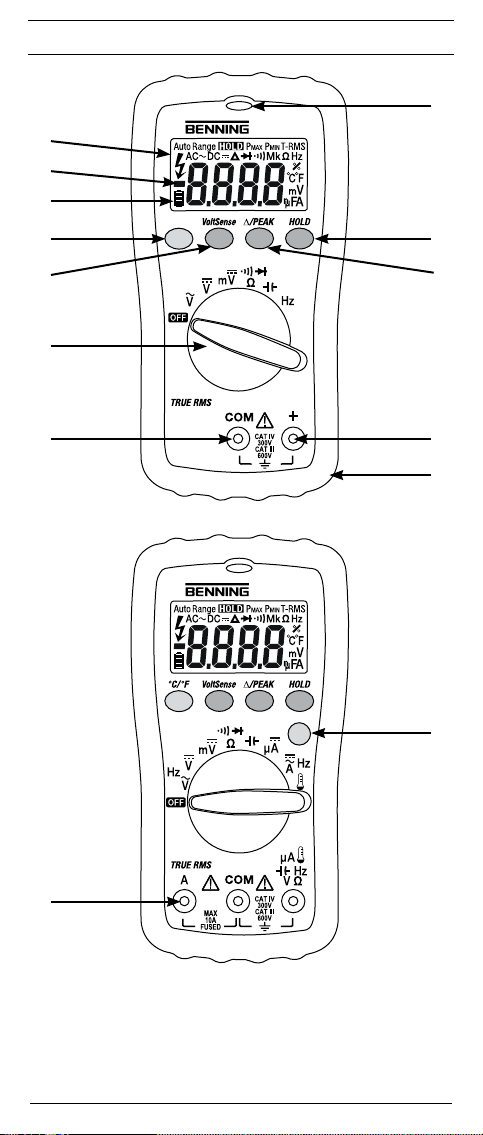
Bild 1: Gerätefrontseite
Fig. 1: Front tester panel
Fig. 1: Panneau avant de l‘appareil
Fig. 1: Parte frontal del equipo
Obr. 1: Přední strana přístroje
σχήμα 1: Μπροστινή όψη
ill. 1: Lato anteriore apparecchio
3
10/ 2015
BENNING MM 5-1/ 5-2
Fig. 1: Voorzijde van het apparaat
Rys.1: Panel przedni przyrządu
Рис. 1. Фронтальная сторона прибора
Resim 1: Cihaz ön yüzü
Page 3
D F E I
MM 5-2
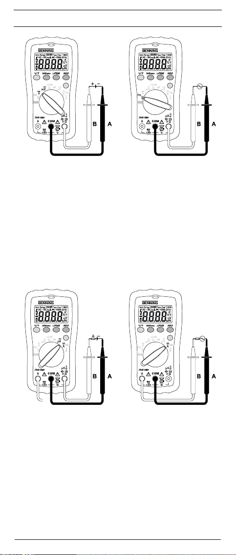
Bild 2: Gleichspannungsmessung
Fig. 2: Direct voltage measurement
Fig. 2: Mesure de tension continue
Fig. 2: Medición de tension contínua
Obr. 2: Měření stejnosměrného napětí
σχήμα 2: μέτρηση DC-τάσης
ill. 2: Misura tensione continua
Fig. 2: Meten van gelijkspanning
Rys.2: Pomiar napięcia stałego
Рис. 2. Измерение напряжения постоянного тока
Resim 2: Doğru Gerilim Ölçümü
MM 5-2
MM 5-2
Bild 3: Wechselspannungsmessung
Fig. 3: Alternating voltage measurement
Fig. 3: Mesure de tension alternative
Fig. 3: Medición de tensión alterna
Obr. 3: Měření střídavého napětí
σχήμα 3: μέτρηση AC-τάσης
ill. 3: Misura tensione alternata
Fig. 3: Meten van wisselspanning
Rys.3: Pomiar napięcia przemiennego
Рис. 3. Измерение напряжения переменного тока
Resim 3: Alternatif Gerilim Ölçümü
MM 5-2
BENNING MM 5-2
Bild 4: Gleichstrommessung
Fig. 4: DC current measurement
Fig. 4: Mesure de courant continu
Fig. 4: Medición de corriente contínua
Obr. 4: Měření stejnosměrného proudu
σχήμα 4: μέτρηση συνεχούς ρεύματος
ill. 4: Misura corrente continua
Fig. 4: Meten van gelijkstroom
Rys.4: Pomiar prądu stałego
Рис. 4. Измерение постоянного тока
Resim 4: Doğru Akım Ölçümü
4
10/ 2015
BENNING MM 5-1/ 5-2
BENNING MM 5-2
Bild 5: Wechselstrommessung
Fig. 5: AC current measurement
Fig. 5: Mesure de courant alternatif
Fig. 5: Medición de corriente alterna
Obr. 5: Měření střídavého proudu
σχήμα 5: AC- μέτρηση
ill. 5: Misura corrente alternata
Fig. 5: Meten van wisselstroom
Rys.5: Pomiar prądu przemiennego
Рис. 5. Измерение переменного тока
Resim 5: Alternatif Akım Ölçümü
Page 4

D F E I
MM 5-2 MM 5-2
Bild 6: Widerstandsmessung
Fig. 6: Resistance measurement
Fig. 6: Mesure de résistance
Fig. 6: Medición de resistencia
Obr. 6: Měření odporu
σχήμα 6: Μέτρηση αντίστασης
ill. 6: Misura di resistenza
Fig. 6: Weerstandsmeting
Rys.6: Pomiar rezystancji
Рис. 6. Измерение сопротивления
Resim 6: Direnç Ölçümü
MM 5-2 MM 5-2
Bild 8: Durchgangsprüfung mit Summer
Fig. 8: Continuity Testing with buzzer
Fig. 8: Contrôle de continuité avec ronfleur
Fig. 8: Control de continuidad con vibrador
Obr. 8: Zkouška průchodu proudu se bzučákem
σχήμα 8: Έλεγχος συνέχειας με ηχητικό σήμα
ill. 8: Prova di continuità con cicalino
Fig. 8: Doorgangstest met akoestisch signaal
Rys.8: Sprawdzenie ciągłości obwodu
Рис. 8. Контроль прохождения тока с зуммером
Resim 8: Sesli Uyarıcı ile Süreklilik kontrolü
Bild 7: Diodenprüfung
Fig. 7: Diode Testing
Fig. 7: Contrôle de diodes
Fig. 7: Verificación de diodos
Obr. 7: Zkouška diod
σχήμα 7: Έλεγχος διόδου
ill. 7: Prova diodi
Fig. 7: Diodecontrole
Rys.7: Pomiar diody
Рис. 7. Проверка диодов
Resim 7: Diyot Kontrolü
Bild 9: Kapazitätsmessung
Fig. 9: Capacity Testing
Fig. 9: Mesure de capacité
Fig. 9: Medición de capacidad
Obr. 9: Měření kapacity
σχήμα 9: Μέτρηση χωρητικότητας
ill. 9: Misura di capacità
Fig. 9: Capaciteitsmeting
Rys.9: Pomiar pojemności
Рис. 9. Измерение емкости
Resim 9: Kapasite Ölçümü
5
10/ 2015
BENNING MM 5-1/ 5-2
Page 5
D F E I
MM 5-2
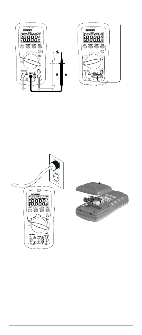
Bild 10: Frequenzmessung
Fig. 10: Frequency measurement
Fig. 10: Mesure de fréquence
Fig. 10: Medición de frecuencia
Obr. 10: Měření kmitočtu
σχήμα 10: Μέτρηση συχνότητας
ill. 10: Misura di frequenza
Fig. 10: Frequentiemeting
Rys.10: Pomiar częstotliwości
Рис. 10. Измерение частоты
Resim 10: Frekans Ölçümü
MM 5-2
MM 5-2
BENNING MM 5-2
Bild 11: Temperaturmessung
Fig. 11: Temperature measurement
Fig. 11: Mesure de température
Fig. 11: Medición de temperatura
Obr. 11: Měření teploty
σχήμα 11: Μέτρηση θερμοκρασίας
ill. 11: Misura di temperatura
Fig. 11: Meten van temperatuur
Rys.11: Pomiar temperatury
Рис. 11. Измерение температуры
Resim 11: Isı Ölçümü
Bild 12: Spannungsindikator
Fig. 12: Voltage indicator
Fig. 12: Indicateur de tension
Fig 12: indicador de tensión
Obr. 12: Indikátor napětí
εικόνα 12: Ένδειξη τάσης
ill. 12: Indicatore di tensione
Fig. 12: Spanningsindicator
Rys. 12: Wskaźnik napięcia
рис. 12: Индикатор напряжения
Resim 12: Gerilim indikatörü
6
10/ 2015
BENNING MM 5-1/ 5-2
Bild 13: Batteriewechsel
Fig. 13: Battery replacement
Fig. 13: Remplacement de la pile
Fig. 13: Cambio de pila
Obr. 13: Výměna baterií
σχήμα 13: Αντικατάσταση μπαταριών
ill. 13: Sostituzione batterie
Fig. 13: Vervanging van de batterijen
Rys.13: Wymiana baterii
Рис. 13. Замена батарейки
Resim 13: Batarya Değişimi
Page 6
D F E I
BENNING MM 5-2
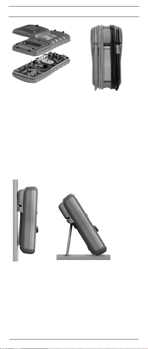
Bild 14: Sicherungswechsel
Fig. 14: Fuse replacement
Fig. 14: Remplacement des fusibles
Fig. 14: Cambio de fusible
Obr. 14: Výměna pojistek
σχήμα 14: αντικατάσταση μπαταρίας
ill. 14: Sostituzione fusibile
Fig. 14: Vervanging van de smeltzekeringen
Rys.14: Wymiana bezpiecznika
Рис. 14. Замена предохранителя
Resim 14: Sigorta Değişimi
Bild 16: Aufstellung des BENNING MM 5-1/ MM 5-2
Fig. 16: Standing up the BENNING MM 5-1/ MM 5-2
Fig. 16: Installation du BENNING MM 5-1/ MM 5-2
Fig. 16: Colocación del BENNING MM 5-1/ MM 5-2
Obr. 16: Postavení přístroje BENNING MM 5-1/ MM 5-2
σχήμα 16: Κρατώντας όρθιο το BENNING MM 5-1/ MM 5-2
ill. 16: Posizionamento del BENNING MM 5-1/ MM 5-2
Fig. 16: Opstelling van de multimeter BENNING MM 5-1/ MM 5-2
Rys.16: Przyrząd BENNING MM 5-1/ MM 5-2 w pozycji stojącej
Рис. 16. Установка прибора BENNING MM 5-1/ MM 5-2
Res.16: BENNING MM 5-1/ MM 5-2’nin kurulumu
Bild 15: Aufwicklung der Sicherheitsmessleitung
Fig. 15: Winding up the safety measuring leads
Fig. 15: Enroulement du câble de mesure de sécurité
Fig. 15: Arrollamiento de la conducción protegida de
Obr. 15: Navíjení bezpečnostního kabelu měřicího
σχήμα 15: Τυλίξτε τα καλώδια μέτρησης
ill. 15: Avvolgimento dei cavetti di sicurezza
Fig. 15: Wikkeling van veiligheidsmeetsnoeren
Rys.15: Zwijanie przewodów pomiarowych
Рис. 15. Намотка безопасного измерительного
Res.15: Emniyet Ölçüm Tesisatının Sarılması
medición
obvodu
провода
7
10/ 2015
BENNING MM 5-1/ 5-2
Page 7
D
Bedienungsanleitung
BENNING MM 5-1/ MM 5-2
Digital-Multimeter zur
- Gleichspannungsmessung
- Wechselspannungsmessung
- Gleichstrommessung (BENNING MM 5-2)
- Wechselstrommessung (BENNING MM 5-2)
- Widerstandsmessung
- Diodenprüfung
- Durchgangsprüfung
- Kapazitätsmessung
- Frequenzmessung
- Temperaturmessung (BENNING MM 5-2)
Inhaltsverzeichnis
1. Benutzerhinweise
2. Sicherheitshinweise
3. Lieferumfang
4. Gerätebeschreibung
5. Allgemeine Angaben
6. Umgebungsbedingungen
7. Elektrische Angaben
8. Messen mit dem BENNING MM 5-1/ MM 5-2
9. Instandhaltung
10. Anwendung des Gummi-Schutzrahmens
11. Technische Daten des Messzubehörs
12. Umweltschutz
1. Benutzerhinweise
Diese Bedienungsanleitung richtet sich an
- Elektrofachkräfte und
- elektrotechnisch unterwiesene Personen
Das BENNING MM 5-1/ MM 5-2 ist zur Messung in trockener Umgebung
vorgesehen. Es darf nicht in Stromkreisen mit einer höheren Nennspannung
als 600 V DC/ AC eingesetzt werden (Näheres hierzu im Abschnitt 6. “Um gebungs bedingungen”).
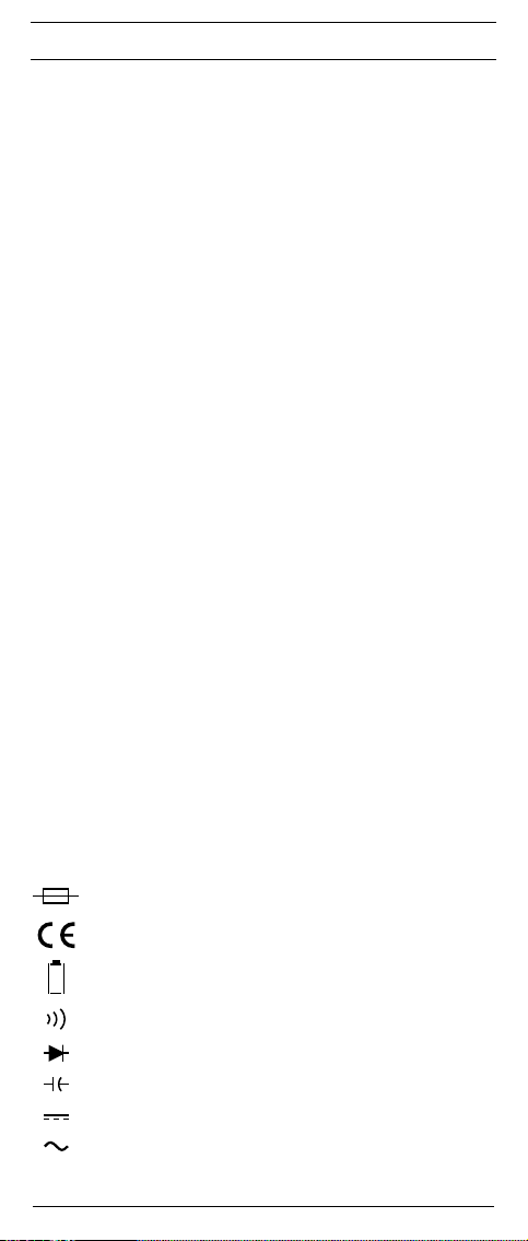
In der Bedienungsanleitung und auf dem BENNING MM 5-1/ MM 5-2 werden
folgende Symbole verwendet:
Warnung vor elektrischer Gefahr!
Steht vor Hinweisen, die beachtet werden müssen, um Gefahren für
Menschen zu vermeiden.
Achtung Dokumentation beachten!
Das Symbol gibt an, dass die Hinweise in der Bedienungsanleitung
zu beachten sind, um Gefahren zu vermeiden.
Dieses Symbol auf dem BENNING MM 5-1/ MM 5-2 bedeutet, dass
das BENNING MM 5-1/ MM 5-2 schutzisoliert (Schutzklasse II)
ausgeführt ist.
Dieses Symbol auf dem BENNING MM 5-2 weist auf die ein ge-
baute Sicherung hin.
Dieses Symbol auf dem BENNING MM 5-1/ MM 5-2 bedeutet, dass
das BENNING MM 5-1/ MM 5-2 konform zu den EU-Richtlinien ist.
Dieses Symbol erscheint in der Anzeige für eine entladene Batterie.
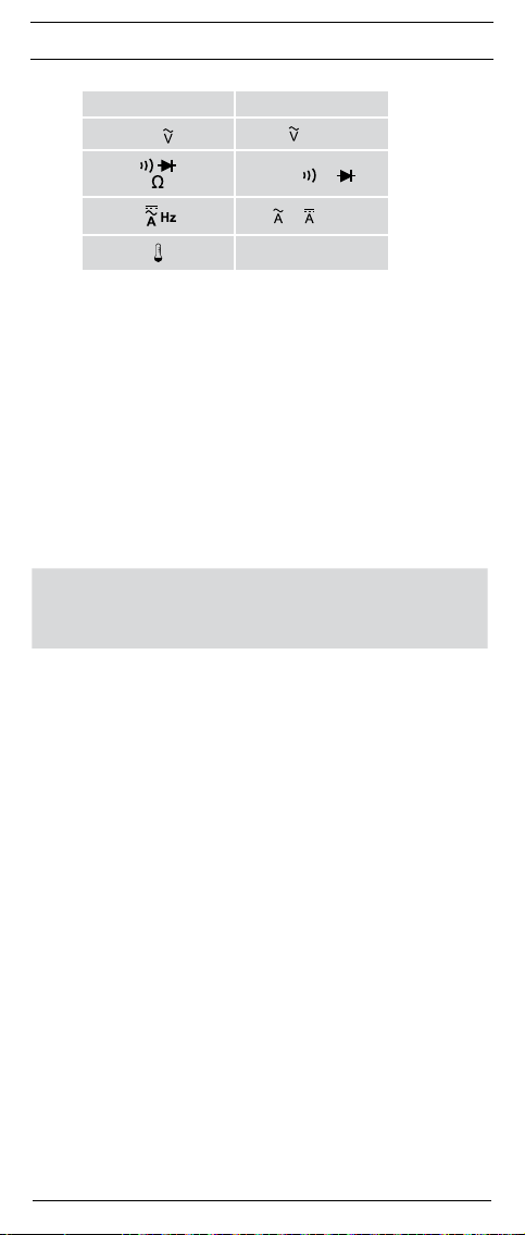
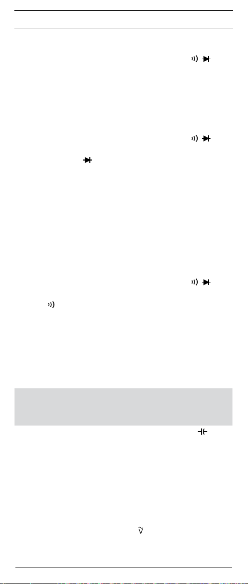
Dieses Symbol kennzeichnet den Bereich “Durchgangsprüfung”.Der
Summer dient der akustischen Er geb nis aus gabe.
Dieses Symbol kennzeichnet den Bereich „Diodenprüfung“.
Dieses Symbol kennzeichnet den Bereich “Kapazitätsprüfung”.
(DC) Gleich- Spannung oder Strom.
(AC) Wechsel- Spannung oder Strom.
Erde (Spannung gegen Erde).
8
10/ 2015
BENNING MM 5-1/ 5-2
Page 8

D
2. Sicherheitshinweise
Das Gerät ist gemäß
DIN VDE 0411 Teil 1/EN 61010-1
DIN VDE 0411 Teil 2-033/EN 61010-2-033
DIN VDE 0411 Teil 031/EN 61010-031 gebaut und geprüft und hat das Werk in
einem sicherheitstechnisch einwandfreien Zustand verlassen.
Um diesen Zustand zu erhalten und einen gefahrlosen Betrieb sicherzustellen,
muss der Anwender die Hinweise und Warnvermerke beachten die in dieser
Anleitung enthalten sind. Fehlverhalten und Nichtbeachtung der Warnungen
kann zu schwerwiegenden Verletzungen oder zum Tode führen.
Extreme Vorsicht bei Arbeiten um blanke Leiter oder Hauptleitungsträger. Ein Kontakt mit Leitern kann einen Elektro-
schock verursachen.
Das BENNING MM 5-1/ MM 5-2 darf nur in Stromkreisen
der Überspannungskategorie III mit max. 600 V Leiter oder
Überspannungskategorie IV mit max. 300 V Leiter gegen Erde
benutzt werden.
Hierzu sind geeignete Messleitungen zu verwenden. Bei
Messungen innerhalb der Messkategorie III oder der Mess katego rie IV darf das hervorstehende leitfähige Teil einer Kon taktspitze der Messleitung nicht länger als 4 mm sein.
Vor Messungen innerhalb der Messkategorie III und der Mess-
kategorie IV müssen, die dem Set beigestellten, mit CAT III
und CAT IV gekennzeichneten, Aufsteckkappen auf die Kontakt spitzen aufgesteckt werden. Diese Maßnahme dient dem
Benutzerschutz.
Beachten Sie, dass Arbeiten an spannungsführenden Teilen
und Anlagen grundsätzlich gefährlich sind. Bereits Span nungen
ab 30 V AC und 60 V DC können für den Menschen lebensgefährlich sein.
Vor jeder Inbetriebnahme überprüfen Sie das Gerät und die
Leitungen auf Beschädigungen.
Ist anzunehmen, dass ein gefahrloser Betrieb nicht mehr möglich ist, ist das
Gerät außer Betrieb zu setzen und gegen unbeabsichtigten Betrieb zu sichern.
Es ist anzunehmen, dass ein gefahrloser Betrieb nicht mehr möglich ist,
-
wenn das Gerät oder die Messleitungen sichtbare Beschädigungen aufweisen,
- wenn das Gerät nicht mehr arbeitet,
- nach längerer Lagerung unter ungünstigen Verhältnissen,
- nach schweren Transportbeanspruchungen,
- wenn das Gerät oder die Messleitungen feucht sind.
Um eine Gefährdung auszuschließen
- berühren Sie die Leitungen nicht an den blanken Messspitzen,
- stecken Sie die Leitungen in die entsprechend gekennzeichneten
Buchsen am Multimeter
Reinigung:
Das Gehäuse regelmäßig mit einem Tuch und Reinigungsmittel
trocken abwischen. Kein Poliermittel oder Lösungsmittel verwenden.
3. Lieferumfang
Zum Lieferumfang des BENNING MM 5-1/ MM 5-2 gehören:
3.1 ein Stück BENNING MM 5-1/ MM 5-2,
3.2 ein Stück Sicherheitsmessleitung, rot (L = 1,4 m),
3.3 ein Stück Sicherheitsmessleitung, schwarz (L = 1,4 m),
3.4 ein Stück Drahttemperatursensor Typ K,(nur BENNING MM 5-2)
3.5 ein Stück Gummi-Schutzrahmen mit Magnethalter
3.6 ein Stück Kompakt-Schutztasche,
3.7 zwei 1,5 V Microbatterien sind zur Erstbestückung im Gerät eingebaut,
3.8 eine Sicherung ist zur Erstbestückung im Gerät eingebaut
(BENNING MM 5-2)
3.9 eine Bedienungsanleitung.
9
10/ 2015
BENNING MM 5-1/ 5-2
Page 9

D
Hinweis auf optionales Zubehör:
- Temperaturfühler (K-Typ) aus V4A-Rohr
Anwendung: Einstichfühler für weichplastische Medien, Flüssigkeiten, Gas
und Luft
Messbereich: - 196 °C bis + 800 °C
Abmessungen: Länge = 210 mm, Rohrlänge = 120 mm, Rohrdurchmesser
= 3 mm, V4A (T.Nr. 044121)
Hinweis auf Verschleißteile:
- Das BENNING MM 5-2 enthält eine Sicherung zum Überlastschutz:
Ein Stück Sicherung Nennstrom 15 A flink (600 V) 50 kA, D = 10,3 mm, L =
38,1 mm (T.Nr. 10149447).
- Das BENNING MM 5-1/ MM 5-2 wird durch zwei eingebaute 1,5-V-Micro-
batterien (IEC LR 03) gespeist.
- Die oben genannten Sicherheitsmessleitungen (geprüftes Zubehör) ent-
sprechen CAT III 1000 V/ CAT IV 600 V und sind für einen Strom von 10 A
zugelassen.
4. Gerätebeschreibung
siehe Bild 1: Gerätefrontseite
Die in Bild 1 angegebenen Anzeige- und Bedienelemente werden wie folgt
bezeichnet:
1
Digitalanzeige, für den Messwert und die Anzeige der Bereichs über-
schreitung,
2
Polaritätsanzeige,
3
Batterieanzeige,
4
Funktions-Taste (blau),
5
VoltSensor-Taste, zur Ermittlung von AC-Spannung gegen Erde,
6
Δ/PEAK-Taste, Relativwert-Funktion bzw. Spitzenwertspeicherung
7
Smart HOLD-Taste,
8
Taste (gelb), Displaybeleuchtung,
9
Drehschalter, für Wahl der Messfunktion,
Buchse (positive1), für V, Ω, , Hz (+) (BENNING MM 5-1) bzw. für V, Ω,
, Hz, μA, (BENNING MM 5-2)
COM-Buchse, gemeinsame Buchse für Strom-, Spannungs-, Widerstands-,
Frequenz-, Temperatur-, Kapazitätsmessungen, Durchgangs- und
Diodenprüfung,
L
Buchse (positive), für 10 A-Bereich, für Ströme bis 10 A,
M
Gummi-Schutzrahmen
N
LED (rot) für Spannungsindikator
1) Hierauf bezieht sich die automatische Polaritätsanzeige für Gleichstrom- und Spannung
5. Allgemeine Angaben
5.1 Allgemeine Angaben zum Multimeter
5.1.1
Die Digitalanzeige 1 ist als 4-stellige Flüssigkristallanzeige mit 16 mm
Schrifthöhe mit Dezimalpunkt ausgeführt. Der größte Anzeigewert ist 6000.
5.1.2 Die Polaritätsanzeige 2 wirkt automatisch. Es wird nur eine Polung
entgegen der Buchsendefinition mit “-” angezeigt.
5.1.3 Die Bereichsüberschreitung wird mit „0L“ oder „- 0L“ und teilweise einer
akustischen Warnung angezeigt.
Achtung, keine Anzeige und Warnung bei Überlast!
5.1.4 Der Drehschalter 9 dient der Anwahl der Messfunktion. Die Mess be-
reichs wahl erfolgt automatisch.
5.1.5 Voltsensor-Taste 5: Die Spannungsindikatorfunktion dient der
Lokalisierung von AC Spannungen gegen Erde. (siehe 8.9)
5.1.6 Die Δ/PEAK-Taste 6 (Relativwert-Funktion) speichert den aktuellen
Anzeigewert und zeigt die Differenz (Offset) zwischen dem gespeicherten Messwert und den folgenden Messwerten auf dem Display an. Wird
die Δ/PEAK-Taste 6 für ca. 2 Sekunden gedrückt, schaltet das Gerät
in die PEAK-Funktion (Spitzenwertspeicherung). Die PEAK-Funktion
erfasst und speichert den positiven und negativen Spitzen-/ Scheitelwert
(> 1 ms) in der Funktion mV, V AC/ DC und mA, A AC/ DC. Durch
Tastendruck kann der Pmax, Pmin und der aktuelle Messwert (Pmax,
Pmin) aufgerufen werden. Durch längeren Tastendruck (2 Sekunden)
wird in den Normalmodus zurückgeschaltet.
5.1.7 Messwertspeicherung „Smart HOLD“: Durch Betätigen der Taste „Smart
HOLD“ 7 lässt sich das Messergebnis speichern. Im Display 1 wird
gleichzeitig das Symbol „HOLD“ eingeblendet. Steigt der Messwert
um 50 Digit über dem gespeicherten Wert, wird die Messwertänderung
durch ein blinkendes Display und durch einen Signalton angezeigt.
(Messwertänderungen zwischen AC und DC Spannung/ Strom werden
nicht erkannt). Erneutes Betätigen der Taste schaltet in den Messmodus
zurück.
10
10/ 2015
BENNING MM 5-1/ 5-2
Page 10
D
5.1.8 Taste (gelb) 8 schaltet die Beleuchtung des Displays an. Die
Ausschaltung erfolgt automatisch nach 2 Minuten oder durch erneute
Tastenbetätigung. Die automatische Abschaltung lässt sich deaktivieren indem Sie die Taste (gelb) 8 betätigen und gleichzeitig das
BENNING MM 5-2 aus der Schalterstellung „OFF“ einschalten.
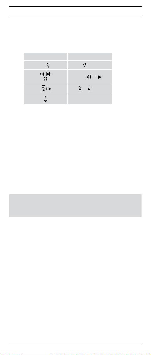
5.1.9 Die Funktions-Taste (blau) 4 wählt die Zweit- oder Drittfunktion der
Drehschalterstellung.
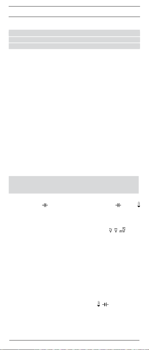
Schalterstellung Funktion
Hz
► Hz
Ω ► ►
5.1.10 Die Messrate des BENNING MM 5-1/ MM 5-2 beträgt nominal 2 Mes-
sungen pro Sekunde für die Digitalanzeige.
5.1.11 Das BENNING MM 5-1/ MM 5-2 wird durch den Drehschalter 9 ein-
oder ausgeschaltet. Ausschaltstellung “OFF”.
5.1.12 Das BENNING MM 5-1/ MM 5-2 schaltet sich nach ca. 20 min selbsttä-
tig ab (APO, Auto-Power-Off). Es schaltet sich wieder ein, wenn eine
Taste betätigt wird.
Die automatische Abschaltung lässt sich deaktivieren indem
sie die Funktions-Taste (blau) 4 betätigen und gleichzeitig das
BENNING MM 5-1/ MM 5-2 aus der Schalterstellung „OFF“ einschalten.
5.1.13
Die Segmente der Digitalanzeige lassen sich überprüfen indem
sie die „Smart HOLD“-Taste 7 betätigen und gleichzeitig das
BENNING MM 5-1/ MM 5-2 aus der Schalterstellung „OFF“ einschalten.
5.1.14 Temperaturkoeffizient des Messwertes: 0,1 x (angegebene
Messgenauigkeit)/ °C < 18 °C oder > 28 °C, bezogen auf den Wert bei
der Referenztemperatur von 23 °C.
5.1.15 Das BENNING MM 5-1/ MM 5-2 wird durch zwei eingebaute
1,5-V-Microbatterien (IEC LR 03) gespeist.
5.1.16 Die Batterieanzeige 3 zeigt permanent die verbleibende Batterie-
kapazität über maximal 3 Segmente an.
Sobald alle Segmente in dem Batteriesymbol erloschen sind
und das Batteriesymbol blinkt, tauschen Sie umgehend die
Batterien gegen neue Batterien aus, um eine Gefährdung durch
Fehlmessungen für den Menschen zu vermeiden.
5.1.17 Die Lebensdauer der Batterien beträgt etwa 300 Stunden (Alkali-
batterie).
5.1.18 Geräteabmessungen:
(L x B x H) = 138 x 68 x 30 mm ohne Gummi-Schutzrahmen
(L x B x H) = 150 x 77 x 44 mm mit Gummi-Schutzrahmen
Gerätegewicht:
180 g ohne Gummi-Schutzrahmen
310 g mit Gummi-Schutzrahmen
5.1.19 Die mitgelieferten Sicherheitsmessleitungen sind ausdrücklich für die
Nenn spannung und dem Nennstrom des BENNING MM 5-1/ MM 5-2
geeignet.
5.1.20 Das BENNING MM 5-1/ MM 5-2 wird durch einen Gummi-Schutz rahmen
M
vor mechanischer Beschädigung geschützt. Der Gummi-Schutzrahmen
M
ermöglicht es, das BENNING MM 5-1/ MM 5-2 während der Messungen
aufzustellen oder über den integrierten Magneten zu befestigen.
6. Umgebungsbedingungen
- Das BENNING MM 5-1/ MM 5-2 ist für Messungen in trockener Umgebung
vorgesehen,
- Barometrische Höhe bei Messungen: Maximal 2000 m,
- Überspannungskategorie/ Aufstellungskategorie: IEC 60664/ IEC 61010-1
→ 600 V Kategorie III, 300 V Kategorie IV,
- Verschmutzungsgrad: 2,
- Schutzart: IP 30 (DIN VDE 0470-1 IEC/ EN 60529)
3 - erste Kennziffer: Schutz gegen Zugang zu gefährlichen Teilen und Schutz
gegen feste Fremdkörper, > 2,5 mm Durchmesser
0 - zweite Kennziffer: Kein Wasserschutz,
- Arbeitstemperatur und relative Luftfeuchte:
11
10/ 2015
BENNING MM 5-1/ 5-2
► ► Hz
°C ► °F
Page 11

D
Bei Arbeitstemperatur von 0 °C bis 30 °C: relative Luftfeuchte kleiner 80 %,
Bei Arbeitstemperatur von 30 °C bis 40 °C: relative Luftfeuchte kleiner 75 %,
Bei Arbeitstemperatur von 40 °C bis 50 °C: relative Luftfeuchte kleiner 45 %,
- Lagerungstemperatur: Das BENNING MM 5-1/ MM 5-2 kann bei Tem pe-
ra turen von - 20 °C bis + 60 °C (Luftfeuchte 0 bis 80 %) gelagert werden.
Dabei sind die Batterien aus dem Gerät herauszunehmen.
7. Elektrische Angaben
Bemerkung: Die Messgenauigkeit wird angegeben als Summe aus
- einem relativen Anteil des Messwertes und
- einer Anzahl von Digit (d.h. Zahlenschritte der letzten Stelle).
Diese Messgenauigkeit gilt bei Temperaturen von 18 °C bis 28 °C und einer
relativen Luftfeuchtigkeit kleiner 80 %.
Der Messwert wird als echter Effektivwert (TRUE RMS, AC-Kopplung) gewonnen und angezeigt. Rechtecksignale (>100 Hz) sind nicht spezifiziert. Bei nicht
sinusförmigen Kurvenformen wird der Anzeigenwert ungenauer. So ergibt sich
für folgende Crest-Faktoren ein zusätzlicher Fehler:
Crest-Factor von 1,0 bis 2,0 zusätzlicher Fehler + 1,0 %
Crest-Factor von 2,0 bis 2,5 zusätzlicher Fehler + 2,5 %
Crest-Factor von 2,5 bis 3,0 zusätzlicher Fehler + 4,0 % (gültig bis 4000 Digit)
7.1 Gleichspannungsbereiche DC
Der Eingangswiderstand beträgt 10 MΩ.
Überlastschutz: 600 V
Messbereich OL Anzeige Auflösung Messgenauigkeit
6,000 V 6,600 V 0,001 V ± (0,5 % des Messwertes + 3 Digit)
60,00 V 66,00 V 0,01 V ± (0,5 % des Messwertes + 3 Digit)
600,0 V 660,0 V 0,1 V ± (0,5 % des Messwertes + 3 Digit)
7.1.1 Gleichspannungsbereich mV DC
Der Eingangswiderstand beträgt 10 MΩ.
Überlastschutz: 600 V
Messbereich OL Anzeige Auflösung Messgenauigkeit
600,0 mV 660,0 mV 0,1 mV ± (0,5 % des Messwertes + 5 Digit)
7.2 Wechselspannungsbereiche AC
Der Eingangswiderstand beträgt 10 MΩ parallel < 100 pF.
Überlastschutz: 600 V
Messbereich OL Anzeige Auflösung
600,0 mV 660,0 mV 0,1 mV ± (2,5 % des Messwertes + 5 Digit)*
6,000 V 6,600 V 0,001 V ± (1,0 % des Messwertes + 3 Digit)
60,00 V 66,00 V 0,01 V ± (1,0 % des Messwertes + 3 Digit)
600,0 V 660,0 V 0,1 V ± (1,0 % des Messwertes + 3 Digit)
* Messbereich ab ≥ 2,0 mV
7.3 Gleichstrombereiche DC (BENNING MM 5-2)
Überlastungsschutz:
- 15 A (600 V AC/ DC)-Sicherung, 50 kA, flink am 10 A - Eingang,
Maximale Messzeit:
- 3 Minuten mit 10 A (Pause > 20 Minuten)
- 15 Sekunden mit 20 A (Pause > 20 Minuten)
Messbereich OL Anzeige Auflösung Messgenauigkeit
6 A 6,600 A 0,001 A ± (1,5 % des Messwertes + 3 Digit)
10 A 20,00 A 0,01 A ± (1,5 % des Messwertes + 3 Digit)
7.3.1 Gleichstrombereiche µA DC (BENNING MM 5-2)
Der Eingangswiderstand beträgt ca. 3 kΩ.
Überlastschutz: 600 V
Messbereich OL Anzeige Auflösung Messgenauigkeit
400,0 µA 440,0 µA 0,1 µA ± (0,9 % des Messwertes + 5 Digit)
4000 µA 4400 µA 1 µA ± (0,9 % des Messwertes + 5 Digit)
12
10/ 2015
AC/DC
AC/DC
AC/DC
im Frequenzbereich 45 Hz - 500 Hz (Sinus)
AC/DC
BENNING MM 5-1/ 5-2
Messgenauigkeit
Page 12

D
7.4 Wechselstrombereiche AC (BENNING MM 5-2)
Überlastungsschutz:
- 15 A (600 V AC/ DC)-Sicherung, 50 kA, flink am 10 A - Eingang,
Maximale Messzeit:
- 3 Minuten mit 10 A (Pause > 20 Minuten)
- 15 Sekunden mit 20 A (Pause > 20 Minuten)
Messbereich OL Anzeige Auflösung
im Frequenzbereich 45 Hz - 500 Hz (Sinus)
6 A 6,600 A 0,001 A ± (1,5 % des Messwertes + 5 Digit)*
10 A 20,00 A 0,01 A ± (1,5 % des Messwertes + 5 Digit)
* Messbereich ab ≥ 20 mA
7.5 Widerstandsbereiche
Überlastschutz: 600 V
AC/ DC
Messbereich OL Anzeige Auflösung Messgenauigkeit
600,0 Ω 660,0 Ω 0,1 Ω ± (0,5 % des Messwertes + 5 Digit)
6,000 kΩ 6,600 kΩ 0,001 kΩ ± (0,5 % des Messwertes + 2 Digit)
60,00 kΩ 66,00 kΩ 0,01 kΩ ± (0,5 % des Messwertes + 2 Digit)
600,0 kΩ 660,0 kΩ 0,1 kΩ ± (0,5 % des Messwertes + 2 Digit)
6,000 MΩ 6,000 MΩ 0,001 MΩ ± (0,5 % des Messwertes + 2 Digit)
40,00 MΩ 40,00 MΩ 0,01 MΩ ± (1,0 % des Messwertes + 5 Digit)*
* Messwerte > 10 MΩ können ein Laufen der Anzeige (max. ± 50 Digit) verur-
sachen
7.6 Diodenprüfung
Überlastschutz: 600 V
Max. Leerlaufspannung: 1,8 V
AC/ DC
Messbereich OL Anzeige Auflösung Messgenauigkeit
1,500 V 1,550 V 0,001 V ± (1,0 % des Messwertes + 3 Digit)
7.7 Durchgangsprüfung
Überlastschutz: 600 V
Der eingebaute Summer ertönt bei einem Widerstand kleiner als 30 Ω bis 200 Ω.
Der Signalton verstummt bei einem Widerstand größer als 200 Ω.
AC/ DC
Messbereich OL Anzeige Auflösung Messgenauigkeit
600,0 Ω 660,0 Ω 0,1 Ω ± (0,5 % des Messwertes + 5 Digit)
7.8 Kapazitätsbereiche
Bedingungen: Kondensatoren entladen und entsprechend der angegebenen
Überlastschutz: 600 V
Polarität anlegen.
AC/ DC
Messbereich OL Anzeige Auflösung Messgenauigkeit
50,00 nF 55,00 nF 0,01 nF ± (2,0 % des Messwertes + 10 Digit)
500,0 nF 550,0 nF 0,1 nF ± (2,0 % des Messwertes + 5 Digit)
5,000 µF 5,500 µF 0,001 µF ± (2,0 % des Messwertes + 5 Digit)
50,00 µF 55,00 µF 0,01 µF ± (2,0 % des Messwertes + 5 Digit)
500,0 µF 550,0 µF 0,1 µF ± (2,0 % des Messwertes + 5 Digit)
1000 µF 1100 µF 1 µF ± (2,0 % des Messwertes + 5 Digit)
7.9 Frequenzbereiche
Überlastschutz: 600 V
AC/ DC
Messbereich OL Anzeige Auflösung Messgenauigkeit
100,00 Hz 100,00 Hz 0,01 Hz ± (0,2 % des Messwertes + 2 Digit)
1000,0 Hz 1000,0 Hz 0,1 Hz ± (0,2 % des Messwertes + 2 Digit)
10,000 kHz 10,000 kHz 0,001 kHz ± (0,2 % des Messwertes + 2 Digit)
50,00 kHz 50,00 kHz 0,01 kHz ± (0,2 % des Messwertes + 2 Digit)
Messgenauigkeit
13
10/ 2015
BENNING MM 5-1/ 5-2
Page 13
D
Minimale Frequenz: 10 Hz
Minimale Empfindlichkeit: > 4 V
> 20 V
> 0,6 A
7.10 Temperaturbereiche °C/ °F (BENNING MM 5-2)
Überlastschutz: 600 V
Messbereich OL Anzeige Auflösung Messgenauigkeit*
-40 °C - +400 °C - 44 °C - +440 °C 0,1 °C ± (1 % des Messwertes + 20 Digit)
-40 °F - +752 °F - 44 °F - +827,2 °F 0,1 °F ± (1 % des Messwertes + 36 Digit)
* Zur angegebenen Messgenauigkeit ist die Messgenauigkeit des K-Typ
Temperatursenor zu addieren.
Drahttemperatursensor K-Typ: Messbereich: - 60 °C bis 200 °C
Messgenauigkeit: ± 2 °C
Die Messgenauigkeit ist gültig für stabile Umgebungstemperaturen < ±1 °C.
Nach einer Änderung der Umgebungstemperatur von ± 2 °C sind die Mess ge-
nauig keitsangaben nach 2 Stunden gültig.
7.11 PEAK HOLD für AC V/ AC A
Zur angegebenen Messgenauigkeit sind ± 150 Digit zu addieren.
Rechtecksignale sind nicht spezifiziert.
8. Messen mit dem BENNING MM 5-1/ MM 5-2
8.1 Vorbereiten der Messung
Benutzen und lagern Sie das BENNING MM 5-1/ MM 5-2 nur bei den angegebenen Lager- und Arbeitstemperaturbedingungen, vermeiden Sie dauernde
Sonneneinstrahlung.
- Angaben von Nennspannung und Nennstrom auf den Sicher heits messleitungen überprüfen. Die zum Lieferumfang gehörenden Sicher heitsmess leitungen entsprechen in Nennspannung und Nennstrom dem
BENNING MM 5-1/ MM 5-2.
- Isolation der Sicherheitsmessleitungen überprüfen. Wenn die Isolation
beschädigt ist, sind die Sicherheitsmessleitungen sofort auszusondern.
- Sicherheitsmessleitungen auf Durchgang prüfen. Wenn der Leiter in der
Sicherheitsmessleitung unterbrochen ist, sind die Sicherheitsmessleitungen
sofort auszusondern.
- Bevor am Drehschalter 9 eine andere Funktion gewählt wird, müssen die
Sicherheitsmessleitungen von der Messstelle getrennt werden.
- Starke Störquellen in der Nähe des BENNING MM 5-1/ MM 5-2 können zu
instabiler Anzeige und zu Messfehlern führen.
8.2 Spannungs- und Strommessung
Maximale Spannung gegen Erdpotential beachten!
Elektrische Gefahr!
Die höchste Spannung, die an den Buchsen,
- COM-Buchse
- Buchse für V, Ω, , Hz (+) (BENNING MM 5-1) bzw. für V, Ω, , Hz, μA,
(BENNING MM 5-2)
- Buchse für 10 A-Bereich L (BENNING MM 5-2)
des BENNING MM 5-1/ MM 5-2 gegenüber Erde liegen darf, beträgt 600 V
CAT III.
8.2.1 Spannungsmessung
- Mit dem Drehschalter 9 die gewünschte Funktion ( , , ) am
BENNING MM 5-1/ MM 5-2 wählen.
- Die schwarze Sicherheitsmessleitung mit der COM-Buchse am
BENNING MM 5-1/ MM 5-2 kontaktieren.
- Die rote Sicherheitsmessleitung mit der Buchse am
BENNING MM 5-1/ MM 5-2 kontaktieren.
- Die Sicherheitsmessleitungen mit den Messpunkten kontaktieren, Messwert
an der Digitalanzeige 1 am BENNING MM 5-1/ MM 5-2 ablesen.
siehe Bild 2: Gleichspannungsmessung
siehe Bild 3: Wechselspannungsmessung
8.2.2 Strommessung (BENNING MM 5-2)
- Mit dem Drehschalter 9 den gewünschten Bereich und Funktion (A AC/DC
oder µA DC) am BENNING MM 5-2 wählen.
- Die schwarze Sicherheitsmessleitung mit der COM-Buchse am
BENNING MM 5-2 kontaktieren.
14
10/ 2015
für VAC (10 Hz - 10 kHz)
eff
für VAC (10 kHz - 50 kHz)
eff
für AAC (10 Hz - 50 kHz)
eff
AC/ DC
BENNING MM 5-1/ 5-2
Page 14
D
- Die rote Sicherheitsmessleitung mit der Buchse für A-Bereich L (bis 10 A
AC/DC) oder mit der Buchse für V, Ω, Hz, µA DC, , (bis 4000 µA
DC) am BENNING MM 5-2 kontaktieren.
- In der Funktion (A AC/DC) mit der Taste (blau) 4 am BENNING MM 5-2 die
zu messende Stromart Gleich- (DC) oder Wechselstrom (AC) wählen.
- Die Sicherheitsmessleitungen mit den Messpunkten kontaktieren, Messwert
an der Digitalanzeige 1 am BENNING MM 5-2 ablesen.
siehe Bild 4: Gleichstrommessung
siehe Bild 5: Wechselstrommessung
8.3 Widerstandsmessung
- Mit dem Drehschalter 9 die gewünschte Funktion (Ω, , ) am
BENNING MM 5-1/ MM 5-2 wählen.
- Die schwarze Sicherheitsmessleitung mit der COM-Buchse am
BENNING MM 5-1/ MM 5-2 kontaktieren.
- Die rote Sicherheitsmessleitung mit der Buchse am
BENNING MM 5-1/ MM 5-2 kontaktieren.
- Die Sicherheitsmessleitungen mit den Messpunkten kontaktieren, den
Messwert an der Digitalanzeige 1 am BENNING MM 5-1/ MM 5-2 ablesen.
siehe Bild 6: Widerstandsmessung
8.4 Diodenprüfung
- Mit dem Drehschalter 9 die gewünschte Funktion (Ω, , ) am
BENNING MM 5-1/ MM 5-2 wählen.
- Mit der Taste (blau) 4 am BENNING MM 5-1/ MM 5-2 die Umschaltung (2 x
betätigen) auf Diodenprüfung ( ) vornehmen.
- Die schwarze Sicherheitsmessleitung mit der COM-Buchse am
BENNING MM 5-1/ MM 5-2 kontaktieren.
- Die rote Sicherheitsmessleitung mit der Buchse am
BENNING MM 5-1/ MM 5-2 kontaktieren.
- Die Sicherheitsmessleitungen mit den Diodenanschlüssen kontaktieren, den
Messwert an der Digitalanzeige 1 am BENNING MM 5-1/ MM 5-2 ablesen.
- Für eine normale in Flussrichtung angelegte Si-Diode wird die Flussspannung
zwischen 0,4 V und 0,8 V angezeigt. Die Anzeige “000“ deutet auf einen
Kurzschluss in der Diode hin.
- Wird keine Flussspannung ermittelt, zunächst Polung der Diode prüfen.
Wird weiterhin keine Flussspannung angezeigt, liegt die Flussspannung der
Diode außerhalb der Messgrenzen.
siehe Bild 7: Diodenprüfung
8.5 Durchgangsprüfung mit Summer und roter LED
- Mit dem Drehschalter 9 die gewünschte Funktion (Ω, , ) am
BENNING MM 5-1/ MM 5-2 wählen.
- Mit der Taste (blau) 4 am BENNING MM 5-1/ MM 5-2 die Umschaltung auf
Durchgangsprüfung ( ) vornehmen.
- Die schwarze Sicherheitsmessleitung mit der COM-Buchse am
BENNING MM 5-1/ MM 5-2 kontaktieren.
- Die rote Sicherheitsmessleitung mit der Buchse am
BENNING MM 5-1/ MM 5-2 kontaktieren.
- Die Sicherheitsmessleitungen mit den Messpunkten kontaktieren.
Unterschreitet der Leitungswiderstand zwischen der COM-Buchse und der
Buchse den Wert 30 Ω bis 200 Ω, ertönt im BENNING MM 5-1/ MM 5-2
der eingebaute Summer und die rote LED N leuchtet auf.
siehe Bild 8: Durchgangsprüfung mit Summer
8.6 Kapazitätsmessung
Kondensatoren vor Kapazitätsmessungen vollständig entladen!
Niemals Spannung an die Buchsen für Kapazitätsmessung
anlegen! Das Gerät kann beschädigt oder zerstört werden! Von
einem beschädigten Gerät kann eine elektrische Gefährdung
ausgehen!
- Mit dem Drehschalter 9 die gewünschte Funktion ( ) am
BENNING MM 5-1/ MM 5-2 wählen.
- Polarität des Kondensators ermitteln und Kondensator vollständig entladen.
- Die schwarze Sicherheitsmessleitung mit der COM-Buchse am
BENNING MM 5-1/ MM 5-2 kontaktieren.
- Die rote Sicherheitsmessleitung mit der Buchse am
BENNING MM 5-1/ MM 5-2 kontaktieren.
- Die Sicherheitsmessleitungen mit dem entladenen Kondensator entsprechend seiner Polarität kontaktieren, Messwert an der Digitalanzeige 1 am
BENNING MM 5-1/ MM 5-2 ablesen.
siehe Bild 9: Kapazitätsmessung
15
10/ 2015
BENNING MM 5-1/ 5-2
Page 15

D
8.7 Frequenzmessung
- Mit dem Drehschalter 9 die gewünschte Funktion (Hz) am BENNING MM 5-1
oder die Funktion ( Hz oder A AC/DC Hz) am BENNING MM 5-2 wählen.
- Die schwarze Sicherheitsmessleitung mit der COM-Buchse am
BENNING MM 5-1/ MM 5-2 kontaktieren.
- Für Frequenzmessung im Spannungsbereich die rote Sicherheitsmessleitung
mit der Buchse am BENNING MM 5-1/ MM 5-2 kontaktieren und
beim BENNING MM 5-2 über die Taste (blau) 4 die Umschaltung auf
Frequenzmessung (Hz) vornehmen.
- Für Frequenzmessung im Strombereich die rote Sicherheitsmessleitung mit
der Buchse L am BENNING MM 5-2 kontaktieren und über die Taste (blau)
4
die Umschaltung (2 x betätigen) auf Frequenzmessung (Hz) vornehmen.
- Beachten Sie die minimale Empfindlichkeit für Frequenzmessungen am
BENNING MM 5-1/ MM 5-2!
- Die Sicherheitsmessleitungen mit den Messpunkten kontaktieren, den
Messwert an der Digitalanzeige 1 am BENNING MM 5-1/ MM 5-2 ablesen.
siehe Bild 10: Frequenzmessung
8.8 Temperaturmessung (BENNING MM 5-2)
- Mit dem Drehschalter 9 die gewünschte Funktion ( ) am BENNING MM 5-2
wählen.
- Mit der Taste (blau) 4 die Umschaltung auf °F bzw. °C vornehmen.
- Den Temperatursensor (Typ K) in die Buchse COM und Buchse polrichtig kontaktieren.
- Die Kontaktstelle (Ende der Sensorleitung) an zu messender Stelle platzieren. Messwert an der Digitalanzeige 1 am BENNING MM 5-2 ablesen.
siehe Bild 11: Temperaturmessung
8.9 Spannungsindikator
Die Spannungsindikatorfunktion dient nicht dem Feststellen
der Spannungsfreiheit. Auch ohne akustischer oder optischer
Signalanzeige kann eine gefährliche Berührungsspannung
anliegen. Elektrische Gefahr!
Die Spannungsindikatorfunktion ist aus jeder Stellung des Drehschalters
möglich (außer Schalterstellung „OFF“). Als Spannungsindikator werden keine
Messleitungen benötigt (berührungslose Erfassung eines Wechselfeldes). Im
Kopfbereich des BENNING MM 5-1/ MM 5-2 befindet sich der Aufnahmesensor.
Bei Betätigung der „VoltSensor“-Taste 5 erlischt die Messwertanzeige. Wird
eine Phasen-Spannung lokalisiert, leuchtet die rote LED N auf und in der
Digitalanzeige wird das Symbol angezeigt. Eine Anzeige erfolgt nur in geerdeten Wechselstromnetzen! Mit einer einpoligen Messleitung kann auch die
Phase ermittelt werden.
Praxistipp:
Unterbrechungen (Kabelbrüche) in offenliegenden Kabeln, z. B. Kabeltrommel,
Lichterkette usw., lassen sich von der Einspeisestelle (Phase) bis zur
Unterbrechungsstelle verfolgen.
Funktionsbereich: ≥ 230 V
siehe Bild 12: Spannungsindikator
8.9.1 Phasenprüfung
- Die rote Sicherheitsmessleitung mit der Buchse am
BENNING MM 5-1/ MM 5-2 kontaktieren.
- Die Sicherheitsmessleitung mit dem Messpunkt (Anlagenteil) kontaktieren
und die Taste „VoltSensor“ 5 betätigen.
- Wenn die rote LED N und das Symbol in der Digitalanzeige angezeigt
wird, liegt an diesem Messpunkt (Anlagenteil) die Phase einer geerdeten
Wechselspannung vor.
9. Instandhaltung
Vor dem Öffnen das BENNING MM 5-1/ MM 5-2 unbedingt
spannungsfrei machen! Elektrische Gefahr!
Die Arbeit am geöffneten BENNING MM 5-1/ MM 5-2 unter Spannung ist
ausschließlich Elektrofachkräften vorbehalten, die dabei besondere
Maßnahmen zur Unfallverhütung treffen müssen.
So machen Sie das BENNING MM 5-1/ MM 5-2 spannungsfrei, bevor Sie das
Gerät öffnen:
- Entfernen Sie zuerst beide Sicherheitsmessleitungen vom Messobjekt.
- Entfernen Sie dann beide Sicherheitsmessleitungen vom
BENNING MM 5-1/ MM 5-2.
- Schalten Sie den Drehschalter 9 in die Schaltstellung “OFF”.
16
10/ 2015
BENNING MM 5-1/ 5-2
Page 16

D
9.1 Sicherstellen des Gerätes
Unter bestimmten Voraussetzungen kann die Sicherheit im Umgang mit dem
BENNING MM 5-1/ MM 5-2 nicht mehr gewährleistet sein; zum Beispiel bei:
- Sichtbaren Schäden am Gehäuse,
- Fehlern bei Messungen,
- Erkennbaren Folgen von längerer Lagerung unter unzulässigen
Bedingungen und
- Erkennbaren Folgen von außerordentlicher Transportbeanspruchung.
In diesen Fällen ist das BENNING MM 5-1/ MM 5-2 sofort abzuschalten, von
den Messstellen zu entfernen und gegen erneute Nutzung zu sichern.
9.2 Reinigung
Reinigen Sie das Gehäuse äußerlich mit einem sauberen und trockenen Tuch
(Ausnahme spezielle Reinigungstücher). Verwenden Sie keine Lösungs- und/
oder Scheuermittel, um das Gerät zu reinigen. Achten Sie unbedingt darauf,
dass das Batteriefach und die Batteriekontakte nicht durch auslaufendes
Batterie-Elektrolyt verunreinigt werden.
Falls Elektrolytverunreinigungen oder weiße Ablagerungen im Bereich der
Batterie oder des Batteriegehäuses vorhanden sind, reinigen Sie auch diese mit
einem trockenen Tuch.
9.3 Batteriewechsel
Vor dem Öffnen das BENNING MM 5-1/ MM 5-2 unbedingt
spannungsfrei machen! Elektrische Gefahr!
Das BENNING MM 5-1/ MM 5-2 wird von zwei 1,5-V-Micro-Batterien gespeist.
Ein Batteriewechsel (siehe Bild 13) ist erforderlich, sobald alle Segmente in dem
Batteriesymbol 3 erloschen sind und das Batteriesymbol blinkt.
So wechseln Sie die Batterie:
- Entfernen Sie die Sicherheitsmessleitungen vom Messkreis.
- Entfernen Sie die Sicherheitsmessleitungen vom BENNING MM 5-1/ MM 5-2.
- Bringen Sie den Drehschalter 9 in die Schaltstellung “OFF”.
- Entfernen Sie den Gummi-Schutzrahmen M vom BENNING MM 5-1/ MM 5-2.
- Legen Sie das BENNING MM 5-1/ MM 5-2 auf die Frontseite und lösen Sie
die Schraube vom Batteriedeckel.
- Heben Sie den Batteriedeckel vom Unterteil ab.
- Heben Sie die entladenen Batterien aus dem Batteriefach.
- Legen Sie die neuen Batterien polrichtig in das Batteriefach.
- Rasten Sie den Batteriedeckel an das Unterteil an, und ziehen Sie die
Schraube an.
- Setzen Sie das BENNING MM 5-1/ MM 5-2 in den Gummi-Schutzrahmen
M
ein.
siehe Bild 13: Batteriewechsel
Leisten Sie Ihren Beitrag zum Umweltschutz! Batterien dürfen
nicht in den Hausmüll. Sie können bei einer Sammelstelle für
Altbatterien bzw. Sondermüll abgegeben werden. Informieren
Sie sich bitte bei Ihrer Kommune.
9.4 Sicherungswechsel (BENNING MM 5-2)
Vor dem Öffnen das BENNING MM 5-2 unbedingt spannungsfrei
machen! Elektrische Gefahr!
Das BENNING MM 5-2 wird durch eine eingebaute Sicherung (G-Schmelzeinsatz)
15 A flink vor Überlastung geschützt (siehe Bild 14).
So wechseln Sie die Sicherung:
- Entfernen Sie die Sicherheitsmessleitungen vom Messkreis.
- Entfernen Sie die Sicherheitsmessleitungen vom BENNING MM 5-2.
- Bringen Sie den Drehschalter 9 in die Schaltstellung “OFF”.
- Entfernen Sie den Gummi-Schutzrahmen M vom BENNING MM 5-2.
- Legen Sie das BENNING MM 5-2 auf die Frontseite und lösen Sie die
Schraube vom Batteriedeckel.
- Heben Sie den Batteriedeckel vom Unterteil ab.
Lösen Sie keine Schrauben an der gedruckten Schaltung des
BENNING MM 5-2!
- Entfernen Sie die vier äußeren Schrauben (schwarz) aus dem Unterteil
(Gehäuseboden).
- Heben Sie den Gehäuseboden im unteren Bereich an und nehmen Sie ihn
17
10/ 2015
BENNING MM 5-1/ 5-2
Page 17

D
im oberen Bereich vom Frontteil ab.
- Heben Sie ein Ende der defekten Sicherung aus dem Sicherungshalter.
- Schieben Sie die defekte Sicherung vollständig aus dem Sicherungshalter.
- Setzen Sie die neue Sicherung mit gleichem Nennstrom, gleicher
Auslösecharakteristik und gleicher Abmessungen ein.
- Ordnen Sie die neue Sicherung mittig in dem Halter an.
- Rasten Sie den Gehäuseboden an das Frontteil an und montieren Sie die
vier Schrauben.
- Rasten Sie den Batteriedeckel an das Unterteil an, und ziehen Sie die
Schraube an.
- Setzen Sie das BENNING MM 5-2 in den Gummi-Schutzrahmen M ein.
siehe Bild 14: Sicherungswechsel
9.5 Kalibrierung
Benning garantiert die Einhaltung der in der Bedienungsanleitung aufgeführten
technischen Spezifikationen und Genauigkeitsangaben für das erste Jahr nach
dem Auslieferungsdatum.
Um die angegebenen Genauigkeiten der Messergebnisse zu erhalten, muss
das Gerät regelmäßig durch unseren Werksservice kalibriert werden. Wir
empfehlen ein Kalibrierintervall von einem Jahr. Senden Sie hierzu das Gerät
an folgende Adresse:
Benning Elektrotechnik & Elektronik GmbH & Co. KG
Service Center
Robert-Bosch-Str. 20
D - 46397 Bocholt
9.6 Ersatzteile
Sicherung F 15 A, 600 V, 50 kA, D = 10,3 mm, L = 38,1 mm (T.Nr. 10149447).
10. Anwendung des Gummi-Schutzrahmens
- Sie können die Sicherheitsmessleitungen verwahren, indem Sie die
Sicher heits messleitungen um den Gummi-Schutzrahmen M wickeln und
die Spitzen der Sicherheitsmessleitungen geschützt an den GummiSchutzrahmen M anrasten (siehe Bild 15).
- Sie können eine Sicherheitsmessleitung so an den Gummi-Schutzrahmen
M
anrasten, dass die Messspitze freisteht, um die Messspitze gemeinsam
mit dem BENNING MM 5-1/ MM 5-2 an einen Messpunkt zu führen.
- Die rückwärtige Stütze am Gummi-Schutzrahmen M ermöglicht, das
BENNING MM 5-1/ MM 5-2 schräg aufzustellen (erleichtert die Ablesung)
(siehe Bild 16).
- Der Gummi-Schutzrahmen M besitzt ein Magnet, der für eine Auf hängemög lichkeit genutzt werden kann.
siehe Bild 15: Aufwicklung der Sicherheitsmessleitung
siehe Bild 16: Aufstellung des BENNING MM 5-1/ MM 5-2
11. Technische Daten des Messzubehörs
- Norm: EN 61010-031,
- Maximale Bemessungsspannung gegen Erde () und Messkategorie:
Mit Aufsteckkappe: 1000 V CAT III, 600 V CAT IV,
Ohne Aufsteckkappe: 1000 V CAT II,
- Maximaler Bemessungsstrom: 10 A,
- Schutzklasse II (), durchgängige doppelte oder verstärkte Isolierung,
- Verschmutzungsgrad: 2,
- Länge: 1,4 m, AWG 18,
- Umgebungsbedingungen:
Barometrische Höhe bei Messungen: Maximal 2000 m,
Temperatur: 0°C bis + 50 °C, Feuchte 50 % bis 80 %
- Verwenden Sie die Messleitungen nur im einwandfreien und sauberen
Zustand sowie entsprechend dieser Anleitung, da ansonsten der vorgesehene Schutz beeinträchtigt sein kann.
- Sondern Sie die Messleitung aus, wenn die Isolierung beschädigt ist oder
eine Unterbrechung in Leitung/ Stecker vorliegt.
- Berühren Sie die Messleitung nicht an den blanken Kontaktspitzen. Fassen
Sie nur den Handbereich an!
- Stecken Sie die abgewinkelten Anschlüsse in das Prüf- oder Messgerät.
12. Umweltschutz
Bitte führen Sie das Gerät am Ende seiner Lebensdauer den zur
Verfügung ste hen den Rückgabe- und Sammelsystemen zu.
18
10/ 2015
BENNING MM 5-1/ 5-2
Page 18

Operating Manual
BENNING MM 5-1/ MM 5-2
Digital Multimeter for
- DC voltage measurement
- AC voltage measurement
- DC current measurement (BENNING MM 5-2)
- AC current measurement (BENNING MM 5-2)
- Resistance measurement
- Diode testing
- Continuity testing
- Capacity measurement
- Frequency measurement
- Temperature measurement (BENNING MM 5-2)
Contents:
1. Operating instructions
2. Safety notes
3. Scope of delivery
4. Description of unit
5. General data
6. Ambient conditions
7. Electrical data
8. Measuring with the BENNING MM 5-1/ MM 5-2
9. Maintenance
10. How to use the protective rubber holster
11. Technical data of the measuring accessories
12. Environmental note
1. Operating Instructions
This operating manual is intended for:
- electricians and
- qualified electrotechnical persons
The BENNING MM 5-1/ MM 5-2 is designed for measurements in dry surroundings. It must not be used in electrical circuits with rated voltages higher than
600 V DC/ AC (for more details, see section 6 “Ambient conditions”).
The following symbols are used in the operating manual and on the
BENNING MM 5-1/ MM 5-2 itself:
Warning of electrical danger!
Indicates instructions which must be followed to avoid danger to
persons.
Important, comply with the documentation!
The symbol indicates that the information provided in the operating
instructions must be followed with in order to avoid risks.
This symbol on the BENNING MM 5-1/ MM 5-2 indicates that the
unit is protection insulated (safety class II).
This symbol on the BENNING MM 5-2 indicates the fuses which
it contains.
This symbol on the BENNING MM 5-1/ MM 5-2 means that the
BENNING MM 5-1/ MM 5-2 complies with the EU directives.
This symbol appears on the display for a discharged battery.
This symbol indicates the “continuity-testing” application. The
buzzer provides an audible signal.
This symbol indicates the “diode-testing” application.
This symbol marks the range “capacity testing”.
(DC) voltage or current.
(AC) voltage or current.
Earth (voltage to earth).
19
10/ 2015
BENNING MM 5-1/ 5-2
Page 19

2. Safety notes
The instrument is built and tested in accordance with
DIN VDE 0411 part 1/EN 61010-1
DIN VDE 0411 part 2-033/EN 61010-2-033
DIN VDE 0411 part 031/EN 61010-031
and has left the factory in perfectly safe technical condition.
To maintain this condition and to ensure safe operation of the multimeter, the
user must observe the notes and warnings given in these instructions at all times.
Improper handling and non-observance of the warnings might involve severe
injuries or danger to life.
WARNING! Be extremely careful when working with bare conductors or main line carrier! Contact with live conductors will
cause an electric shock!
The BENNING MM 5-1/ MM 5-2 may be used only in electrical
circuits of over voltage category III with a maximum voltage of
600 V or of over voltage category IV with a maximum voltage of
300 V between the conductor and ground.
Only use suitable measuring leads for this. With measurements
within measurement category III or measurement category IV,
the projecting conductive part of a contact tip of the measuring
leads must not be longer than 4 mm.
Prior to carrying out measurements within measurement category III and measurement category IV, the push-on caps
provided with the set and marked with CAT III and CAT IV must
be pushed onto the contact tips. The purpose of this measure
is user protection.
Remember that work on electrical components of all kinds is
dangerous. Even low-voltages of 30 V AC and 60 V DC may be
dangerous to human life.
Before starting the multimeter, always check it as well as all
measuring leads and wires for signs of damage.
Should it appear that safe operation of the multimeter is no longer possible, it
should be shut down immediately and secured to prevent that it is switched on
accidentally.
It may be assumed that safe operation is no longer possible:
- if the instrument or the measuring leads show visible signs of damage, or
- if the multimeter no longer works, or
- after long periods of storage under unfavourable conditions, or
- after being subject to rough transportation, or
- if the device or the measuring leads are exposed to moisture, or
In order to avoid danger,
- do not touch the bare probe tips of the measuring leads
3. Scope of delivery
The following items make up the standard BENNING MM 5-1/ MM 5-2 package:
3.1 one BENNING MM 5-1/ MM 5-2,
3.2 one safety measuring lead, red (L = 1.4 m),
3.3 one safety measuring lead, black (L = 1.4 m),
3.4 one wire temperature sensor, type K (only BENNING MM 5-2)
3.5 one protective rubber holster with magnetic holder,
3.6 one compact protection carrying case,
3.8 two 1.5 V micro (AAA) batteries are integrated into the device,
3.9 one fuse for initial assembly is integrated into the device
20
10/ 2015
measuring leads,
- insert the measurement leads in the appropriately
designated measuring sockets on the multimeter
Cleaning:
Regularly wipe the housing by means of a dry cloth and
cleaning agent. Do not use any polishing agents or solvents!
(BENNING MM 5-2),
3.9
one operating manual.
BENNING MM 5-1/ 5-2
Page 20

Note on optional accessory:
- Temperature probe (K-type) made of V4A tube
application: insertion probe for soft-plastic materials, liquids, gas and air
measuring range: - 196 °C up to 800 °C
dimensions: length = 210 mm, tube length = 120 mm, tube diameter =
3 mm, V4A (P.no. 044121)
Note on replaceable parts:
- The BENNING MM 5-2 contains fuses for overload protection:
One fuse rated 15 A rapid-acting (600 V) 50 kA, D = 10.3 mm, L = 38.1 mm
(P.no. 10149447).
- The BENNING MM 5-1/ MM 5-2 is supplied by means of two integrated
1.5 V micro (AAA) batteries (IEC LR 03).
- The above mentioned safety cable (tested spare part) are approved in
accordance with CAT III 1000 V/ CAT IV 600 V and for a current up 10 A.
4. Description of unit
See fig. 1: Front panel
The display and operating elements shown in fig. 1 are as follows:
Digital display, for the measurement reading and display for overrange
indication,
Polarity display,
Battery display,
Function key (blue),
VoltSensor key, for determining AC voltage to earth,
Δ/PEAK key, relative value function and peak value storage
Smart HOLD key,
8
Button (yellow), display illumination,
Rotating switch, for selecting measuring function.
Socket (positive1) for V, Ω, , Hz (+) (BENNING MM 5-1) or for V, Ω, ,
Hz, μA, , (BENNING MM 5-2)
COM socket, joint socket for measurement of current, voltage, resistance,
frequency, temperature, capacity, continuity and diode testing,
Socket (positive), for 10-A range, for currents up to 10 A
Protective rubber holster
LED (red) for voltage indicator
1) The automatic polarity display for DC current and voltage refers to this.
5. General data
5.1 General data on multimeter
5.1.1 The digital display 1 is designed as a 4 digit liquid-crystal indicator with 16
mm digit height and decimal point. The highest value displayed is 6000.
5.1.2 The polarity indication functions automatically. Only a polarity con-
trary to the socket definition is indicated, as “-”.
5.1.3 The range overload will be displayed with “OL” or “-OL” and sometimes
with an acoustic signal.
Attention: no display or warning by complete overload.
5.1.4 The rotary switch 9 is intended for selecting the measuring function.
The measuring range is selected automatically.
5.1.5 Volt sensor key 5: The voltage indicator function is intended for local-
izing AC voltages to earth (see 8.9).
5.1.6 Press the Δ/PEAK key 6 (relative value function) to store the currently
displayed value and to display the difference (offset) between the stored
measured value and the following measured values. Press the Δ/PEAK
key 6 for 2 seconds to switch over to the “PEAK” function (peak value
storage). The “PEAK” function detects and stores the positive and
negative peak/ crest value (> 1 ms) in the mV, V AC/ DC and mA, A
AC/ DC function. Press the key to call up Pmax, Pmin and the currently
measured value (Pmax, Pmin). Press the key for approx. 2 seconds to
switch the device back to normal operating mode.
5.1.7 “Smart HOLD” - storage of measurement reading: When the “Smart HOLD”
key is pressed, the measurement reading is stored in the memory.
The symbol “HOLD” appears in the display 1 at the same time. If the
measured value increases by 50 digit above the saved value the change
in measured value is shown by a blinking display and by a signal tone.
(changes of measured values between AC and DC voltage/ current will
not be recognized).
5.1.8 Press the yellow key 8 to activate the display illumination. The device is
switched off automatically after 2 seconds or by pressing the key again.
Deactivate the automatic switch-off by pressing the key (yellow) 8 and
simultaneously switching the BENNING MM 5-2 ON from the switch
position “OFF”.
5.1.9 The function key (blue) 4 serves to select the secondary or third func-
21
10/ 2015
BENNING MM 5-1/ 5-2
Page 21
tion of the rotary switch position.
Switch position Function
Hz
► Hz
Ω ► ►
5.1.10 The nominal measurement rate of the BENNING MM 5-1/ MM 5-2 is 2
measurements per sec. for the digital display.
5.1.11 The BENNING MM 5-1/ MM 5-2 is switched on and off by the rotating
switch . Switch-off position “OFF”.
5.1.12 The BENNING MM 5-1/ MM 5-2 switches off automatically after approx.
20 minutes (APO, Auto-Power-Off). It will switch on again as soon
as a key is pressed. Deactivate the automatic switch-off by pressing the function key (blue) 4 and simultaneously switching the
BENNING MM 5-1/ MM 5-2 ON from the switch position “OFF”.
5.1.13 Check the segments of the digital display by pressing the “Smart HOLD”
key 7 and simultaneously switching the BENNING MM 5-1/ MM 5-2
ON from the switch position “OFF”.
5.1.14 Temperature coefficient of measurement value: 0.1 x (stated measure-
ment accuracy)/ °C < 18 °C or > 28 °C relative to the value at the reference temperature of 23 °C.
5.1.15 The BENNING MM 5-1/ MM 5-2 is supplied by means of two 1.5 V micro
(AAA) batteries (IEC LR 03).
5.1.16 The battery display 3 permanently shows the remaining battery capac-
ity over a maximum 3 segments.
As soon as all segments in the battery symbol have gone off
and the battery symbol blinks please exchange the battery for
a new battery immediately in order to avoid a risk through false
measurements for people.
5.1.17 The life span of a battery is approx. 300 hours (alkali battery).
5.1.18 Appliance dimensions:
(L x W x H) = 138 x 68 x 30 mm without protective rubber holster
(L x W x H) = 150 x 77 x 44 mm with protective rubber holster
Weight:
180 g without protective rubber holster
310 g with protective rubber holster
5.1.19 The safety measuring leads are expressly suitable for the rated voltage
and power of the BENNING MM 5-1/ MM 5-2.
5.1.20 The BENNING MM 5-1/ MM 5-2 is protected against mechanical dam-
age by a protective rubber holster M. The protective rubber holster M
allows to set up the BENNING MM 5-1/ MM 5-2 when making measurements or to attach it by means of the integrated magnet.
6. Ambient conditions
- The BENNING MM 5-1/ MM 5-2 is designed only for measuring in dry surroundings,
- Maximum barometric height during measurement: 2000 m.
- Overvoltage category / setting category: IEC 60664/ IEC 61010-1 → 600 V
category III; 300 V category IV.
- Degree of contamination: 2.
- Protection class: IP 30 (DIN VDE 0470-1 IEC/ EN 60529).
IP 30 means: Protection against access to dangerous parts and protection
against solid impurities of a diameter > 2.5 mm, (3 - first index). No protection against water, (0 - second index).
- Operating temperature and relative humidity:
At operating temperatures of 0 °C to 30 °C: relative humidity under 80 %.
At operating temperatures of 30 °C to 40 °C: relative humidity under 75 %.
- At operating temperatures of 40 °C to 50 °C: relative humidity under 45 %.
- Storage temperature: The BENNING MM 5-1/ MM 5-2 can be stored at
temperatures from - 20 °C to + 60 °C (humidity 0 up to 80 %). The batteries
must be removed from the unit.
► ► Hz
°C ► °F
22
10/ 2015
BENNING MM 5-1/ 5-2
Page 22

7. Electrical data
Note: The measurement accuracy is stated as the sum of
- a relative proportion of the measurement value and
- a number of digits (i.e. numerical steps of the last place).
This measurement accuracy applies for a temperature of 18 °C to 28 °C and a
maximum relative humidity of max. 80 %.
The measurement value is obtained as a true RMS value (AC coupling) and
displayed as such. Square-wave signals (> 100 Hz) are not specified. With
non-sinusoidal curves, the value displayed is less accurate. This results in an
additional error for the following crest factors:
Crest factor of 1.0 to 2.0, additional error + 1.0 %.
Crest factor of 2.0 to 2.5, additional error + 2.5 %.
Crest factor of 2.5 to 3.0, additional error + 4.0 % (applies to up to 4000 digits).
7.1 DC voltage ranges
The input resistance is 10 MΩ
Overload protection: 600 V
Measuring range OL indication Resolution Measurement accuracy
6.000 V 6.600 V 0.001 V ± (0.5 % of reading + 3 digits)
60.00 V 66.00 V 0.01 V ± (0.5 % of reading + 3 digits)
600.0 V 660.0 V 0.1 V ± (0.5 % of reading + 3 digits)
7.1.1 DC voltage ranges mV DC
The input resistance is 10 MΩ
Overload protection: 600 V
Measuring range OL indication Resolution Measurement accuracy
600.0 mV 660.0 mV 0.1 mV ± (0.5 % of reading + 5 digits)
7.2 AC voltage ranges
The input resistance is 10 MΩ parallel < 100 pF.
Overload protection: 600 V
Measuring
600.0 mV 660.0 mV 0.1 mV ± (2.5 % of reading + 5 digits)*
6.000 V 6.600 V 0.001 V ± (1.0 % of reading + 3 digits)
60.00 V 66.00 V 0.01 V ± (1.0 % of reading + 3 digits)
600.0 V 660.0 V 0.1 V ± (1.0 % of reading + 3 digits)
* Measuring range from ≥ 2.0 mV
7.3 DC current ranges (BENNING MM 5-2)
Overload protection:
- 15 A (600 V AC/ DC) fuse, 50 kA, rapid on 10 A input
Max. measuring time:
- 3 minutes at 10 A (pause > 20 minutes)
- 15 secondes at 20 A (pause > 20 minutes)
Measuring range OL indication Resolution Measurement accuracy
7.3.1 µA DC current ranges (BENNING MM 5-2)
The input resistance is approx. 3 kΩ.
Overload protection: 600 V
Measuring range OL indication Resolution Measurement accuracy
7.4 AC current ranges (BENNING MM 5-2)
Overload protection:
- 15 A (600 V AC/ DC) fuse, 50 kA, rapid on 10 A input
Max. measuring time:
- 3 minutes at 10 A (pause > 20 minutes)
- 15 secondes at 20 A (pause > 20 minutes)
23
10/ 2015
OL indication Resolution
range
6 A 6.600 A 0.001 A ± (1.5 % of reading + 3 digits)
10 A 20.00 A 0.01 A ± (1.5 % of reading + 3 digits)
400.0 µA 440.0 µA 0.1 µA ± (0.9 % of reading + 5 digits)
4000 µA 4400 µA 1 µA ± (0.9 % of reading + 5 digits)
AC/DC
AC/DC
AC/DC
AC/DC
BENNING MM 5-1/ 5-2
Measurement accuracy
in frequency range 45 Hz - 500 Hz (sine)
Page 23

Measuring
range
OL indication Resolution
Measurement accuracy
in frequency range 45 Hz - 500 Hz (sine)
6 A 6.600 A 0.001 A ± (1.5 % of reading + 5 digits)*
10 A 20.00 A 0.01 A ± (1.5 % of reading + 5 digits)
* Measuring range from ≥ 20 mA
7.5 Resistance ranges
Overload protection: 600 V
AC/ DC
Measuring range OL indication Resolution Measurement accuracy
600.0 Ω 660.0 Ω 0.1 Ω ± (0.5 %
6.000 kΩ 6.600 kΩ 0.001 kΩ ± (0.5 %
60.00 kΩ 66.00 kΩ 0.01 kΩ ± (0.5 %
600.0 kΩ 660.0 kΩ 0.1 kΩ ± (0.5 %
6.000 MΩ 6.000 MΩ 0.001 MΩ ± (0.5 %
40.00 MΩ 40.00 MΩ 0.01 MΩ ± (1.0 %
* Measured values > 10 MΩ might cause changing values on the display
(max. ± 50 digits).
7.6 Diode testing
Overload protection: 600 V
Max. no-load voltage: 1.8 V
AC/ DC
of reading + 5
of reading + 2
of reading + 2
of reading + 2
of reading + 2
of reading + 5
digits)
digits
digits
digits
digits
digits)*
)
)
)
)
Measuring range OL indication Resolution Measurement accuracy
1.500 V 1.550 V 0.001 V ± (1.0 %
7.7 Continuity testing
Overload protection: 600 V
The built-in buzzer sounds in the case of a resistance R less than 30 Ω up
to 200 Ω. For a resistance R higher than 200 Ω, the buzzer does not emit an
acoustic signal.
AC/ DC
of reading + 3
digits
)
Measuring range OL indication Resolution Measurement accuracy
600.0 Ω 660.0 Ω 0.1 Ω ± (0.5 % of reading + 5 digits)
7.8 Capacity ranges
Conditions: capacitors discharged and connected in accordance with the polar-
Overload protection: 600 V
ity stated.
AC/ DC
Measuring range OL indication Resolution Measurement accuracy
50.00 nF 55.00 nF 0.01 nF ± (2.0 % of reading + 10 digits)
500.0 nF 550.0 nF 0.1 nF ± (2.0 % of reading + 5 digits)
5.000 µF 5.500 µF 0.001 µF ± (2.0 % of reading + 5 digits)
50.00 µF 55.00 µF 0.01 µF ± (2.0 % of reading + 5 digits)
500.0 µF 550.0 µF 0.1 µF ± (2.0 % of reading + 5 digits)
1000 µF 1100 µF 1 µF ± (2.0 % of reading + 5 digits)
7.9
Frequency ranges
Overload protection: 600 V
AC/ DC
Measuring range OL indication Resolution Measurement accuracy
100.00 Hz 100.00 Hz 0.01 Hz ± (0.2 % of reading + 2 digits)
1000.0 Hz 1000.0 Hz 0.1 Hz ± (0.2 % of reading + 2 digits)
10.000 kHz 10.000 kHz 0.001 kHz ± (0.2 % of reading + 2 digits)
50.00 kHz 50.00 kHz 0.01 kHz ± (0.2 % of reading + 2 digits)
Minimum frequency: 10 Hz
Minimum sensitivity: > 4 V
> 20 V
> 0,6 A
for VAC (10 Hz - 10 kHz)
eff
for VAC (10 kHz - 50 kHz)
eff
for AAC (10 Hz - 50 kHz)
eff
24
10/ 2015
BENNING MM 5-1/ 5-2
Page 24
7.10 Temperature ranges °C/ °F (BENNING MM 5-2)
Overload protection: 600 V
Measuring range OL indication Resolution Measurement accuracy*
-40 °C - +400 °C - 44 °C - +440 °C 0.1 °C ± (1 % of reading + 20 digits)
-40 °F - +752 °F - 44 °F - +827.2 °F 0.1 °F ± (1 % of reading + 36 digits)
* The measuring accuracy of the K-type temperature sensor has to be added
to the specified measuring accuracy.
Wire temperature sensor (type K): Measuring range: - 60 °C to 200 °C
Measurement accuracy: ± 2 °C
The measuring accuracy applies to stable ambient temperatures < ± 1 °C. After
a change of the ambient temperature of ± 2 °C, the measuring accuracy data
will apply after 2 hours.
7.11 PEAK HOLD for AC V/ AC A
Please add ± 150 digits to the specified measuring accuracy.
Square-wave signals are not specified.
8. Measuring with the BENNING MM 5-1/ MM 5-2
8.1 Preparation for measuring
Store and use the BENNING MM 5-1/ MM 5-2 only under the correct temperature conditions stated. Always avoid longer exposure to sunlight.
- Check the rated voltage and rated current stated on the safety measuring
leads. The safety measuring leads supplied with the unit are suitable for the
rated voltage and current of the BENNING MM 5-1/ MM 5-2.
- Check the insulation of the safety measuring leads. If the insulation is damaged in any way, do not use the leads.
- Check the continuity of the safety measuring leads. If the conductor in the
safety measuring lead is interrupted, do not use the leads.
- Before selecting another function with the rotating switch , always disconnect the safety measuring leads from the measuring point.
- Sources of strong current in the vicinity of the BENNING MM 5-1/ MM 5-2
may cause unstable or incorrect readings.
8.2 Voltage and current measurement
Always observe the maximum voltage to earth potential!
Electrical hazard!
The maximum voltage which may be applied to the sockets
- COM socket
- socket for V, Ω, , Hz (+) (BENNING MM 5-1) or for V, Ω, , Hz, μA,
- socket for 10 A range L (BENNING MM 5-2)
of the BENNING MM 5-1/ MM 5-2 to earth is 600 V CAT III.
8.2.1 Voltage measurement
- With the rotating switch , select the desired function ( , , ) on the
BENNING MM 5-1/ MM 5-2.
- Connect the black safety measuring lead to the COM socket on the
BENNING MM 5-1/ MM 5-2.
- Connect the red safety measuring lead to the socket on the
BENNING MM 5-1/ MM 5-2.
- Connect the safety measuring leads to the measuring points. Read the measurement value displayed in the digital display of the BENNING MM 5-1/ MM 5-2.
See fig. 2: DC-voltage measurement
See fig. 3: AC-voltage measurement
8.2.2 Current measurement (BENNING MM 5-2)
- With the rotating switch , select the desired range and function (A AC/DC
or µA DC) on the BENNING MM 5-2.
-
Connect the black safety measuring lead to the COM socket on the
BENNING MM 5-2.
- Connect the red safety measuring lead to the jack for the A range L (up to
10 A AC/DC) or to the jack for V, Ω, Hz, μA DC, , (up to 4000 μA
DC) of the BENNING MM 5-2.
- In the (A AC/DC) function, select the current type to be measured – direct
current (DC) or alternating current (AC) – by pressing the key (blue) 4 of
the BENNING MM 5-2.
- Connect the safety measuring leads to the measuring points. Read the measurement value displayed in the digital display of the BENNING MM 5-2.
See fig. 4: DC-current measurement
25
10/ 2015
(BENNING MM 5-2)
AC/ DC
BENNING MM 5-1/ 5-2
Page 25
See fig. 5: AC-current measurement
8.3 Resistance measurement
- With the rotating switch , select the desired function (Ω, , ) on the
BENNING MM 5-1/ MM 5-2.
- Connect the black safety measuring lead to the COM socket on the
BENNING MM 5-1/ MM 5-2.
- Connect the red safety measuring lead to the socket on the
BENNING MM 5-1/ MM 5-2.
- Connect the safety measuring leads to the measuring points. Read the measurement value displayed in the digital display of the BENNING MM 5-1/ MM 5-2.
See fig. 6: Resistance measurement
8.4 Diode testing
- With the rotating switch , select the desired function (Ω, , ) on the
BENNING MM 5-1/ MM 5-2.
- Using the blue key on the BENNING MM 5-1/ MM 5-2, switch to (press
twice) diode testing ( ).
- Connect the black safety measuring lead to the COM socket on the
BENNING MM 5-1/ MM 5-2.
- Connect the red safety measuring lead to the socket on the
BENNING MM 5-1/ MM 5-2.
- Contact the diode connections with the safety measuring leads and
read the measurement value displayed in the digital display of the
BENNING MM 5-1/ MM 5-2.
- For a normal silicone diode located in flow direction, the flow voltage
between 0.4 V and 0.8 V is displayed. If “000” appears in the display, there
may be a short circuit in the diode.
- If no forward voltage is detected, first check the polarity of the diode. If still
no forward voltage is displayed, the forward voltage of the diode is beyond
the measuring limits.
See fig. 7: Diode testing
8.5 Continuity testing with buzzer and red LED
- With the rotating switch , select the desired function (Ω, , ) on the
BENNING MM 5-1/ MM 5-2.
- Using the blue key 4 on the BENNING MM 5-1/ MM 5-2, switch to continuity
testing ( ).
- Connect the black safety measuring lead to the COM socket on the
BENNING MM 5-1/ MM 5-2.
- Connect the red safety measuring lead to the socket on the
BENNING MM 5-1/ MM 5-2.
- Contact the measuring points with the safety measuring leads. If the line
resistance between the COM jack and the jack falls below 30 Ω to
200 Ω, the integrated buzzer of the BENNING MM 5-1/ MM 5-2 sounds and
the red LED N lights up.
See fig. 8: Continuity testing with buzzer
8.6 Capacitance measurement
Discharge capacitors fully before measurement! Never apply
voltage to the sockets for capacitance measurement as this
may cause irreparable damage to the unit. A damaged unit may
represent an electrical hazard!
- With the rotating switch , select the desired function ( ) on the
BENNING MM 5-1/ MM 5-2.
- Determine the polarity of the capacitor and discharge it completely.
- Connect the black safety measuring lead to the COM socket on the
BENNING MM 5-1/ MM 5-2.
- Connect the red safety measuring lead to the socket on the
BENNING MM 5-1/ MM 5-2.
- Contact the discharged capacitor with the safety measuring leads observing
correct polarity. Read the measurement value on the digital display of the
BENNING MM 5-1/ MM 5-2.
See fig. 9: Capacity measurement
8.7 Frequency measurement
- Use the rotary switch 9 to select the desired function (Hz) of the
BENNING MM 5-1 or the function ( Hz or A AC/DC Hz) of the
BENNING MM 5-2.
- Connect the black safety measuring lead to the COM socket on the
BENNING MM 5-1/ MM 5-2.
- For frequency measurement in the voltage range, connect the red safety
26
10/ 2015
BENNING MM 5-1/ 5-2
Page 26

measuring lead to the jack of the BENNING MM 5-1/ MM 5-2 and press
the key (blue) 4 of the BENNING MM 5-2 to switch over to frequency measurement (Hz).
- For frequency measurement in the current range, connect the red safety
measuring lead to the jack L of the BENNING MM 5-2 and press the key
(blue) 4 (press twice) to switch over to frequency measurement (Hz).
- Remember the minimum sensitivity for frequency measurements using the
BENNING MM 5-1/ MM 5-2!
- Contact the measuring points with the safety measuring leads
and read the measurement result on the digital display on the
BENNING MM 5-1/ MM 5-2.
See fig. 10: Frequency measurement
8.8 Temperature measurement (BENNING MM 5-2)
- With the rotating switch , select the desired function ( ) on the
BENNING MM 5-2
- Press the blue key 4 to switch over to °F or °C.
- Connect the temperature sensor (type K) to the COM jack and to the jack
observing correct polarity.
- Place the contact point (end of the sensor lead) on the point to be
measured. Read the measurement value on the digital display of the
BENNING MM 5-2.
See fig. 11: Temperature measurement
8.9 Voltage indicator
The voltage indicator function is not intended for testing the
absence of voltage. Even without an indication or acoustic
signal, a dangerous contact voltage might be applied. Electrical
danger!
The voltage indicator function is possible from each position of the rotary switch
(except for switch position “OFF”). No measuring lines are required as voltage
indicator (non-contact detection of an alternating field). The detector is located
on the top side of the BENNING MM 5-1/ MM 5-2. Press the “VoltSensor” key 5
and the measured value indication disappears. If a phase voltage is localized,
the red LED N lights up and the symbol is shown on the display.An indication
is made in earthed AC current networks only! The phase can be determined by
means of a single-pole measuring line.
Practical hint:
Interruptions (cable breaks) in cables lying around openly such as e.g. cable
reels, fairy lights etc. can be traced from the feeding point (phase) to the point
of interruption.
Functional range: ≥ 230 V
See figure 12: Voltage indicator
8.9.1 Phase test
- Connect the red safety measuring lead to the jack for of the
BENNING MM 5-1/ MM 5-2.
- Bring the safety measuring line into contact with the measuring point of the
system part and press the „VoltSensor“ key 5.
- If the red LED N lights up and the symbol is shown on the display, the
phase of an earthed alternating voltage is applied to this measuring point
(system part).
9. Maintenance
Before opening the BENNING MM 5-1/ MM 5-2, ensure that it is
not connected to a source of voltage! Electrical hazard!
Any work required on the BENNING MM 5-1/ MM 5-2 when it is under voltage must
be done only by a qualified electrician. Special steps must be taken to prevent
accidents. Before opening the BENNING MM 5-1/ MM 5-2, remove it from all sources
of voltage as follows:
- First remove both safety measuring leads from the measurement points.
- Remove both safety measuring leads from the BENNING MM 5-1/ MM 5-2
- Turn the rotating switch to “OFF”.
9.1 Securing the unit
Under certain circumstances, the safety of the BENNING MM 5-1/ MM 5-2 can
no longer be guaranteed. This may be the case if:
- there are visible signs of damage on the unit,
- errors occur in measurements,
-
the unit has been stored for a long period of time under the wrong conditions, and
- if the unit has been subjected to rough handling during transport.
27
10/ 2015
BENNING MM 5-1/ 5-2
Page 27

In these cases, the BENNING MM 5-1/ MM 5-2 must be switched off immediately,
removed from the measuring points and secured to prevent it from being used again.
9.2 Cleaning
Clean the outside of the unit with a clean dry cloth. (Exception: any type of
special cleaning cloth). Never use solvents or abrasives to clean the testing unit.
Ensure that the battery compartment and the battery contacts have not been
contaminated by electrolyte leakage.
If any electrolyte or white deposits are seen near to the battery or in the battery
compartment, remove them with a dry cloth, too.
9.3 Battery replacement
Before opening the BENNING MM 5-1/ MM 5-2, ensure that it is
not connected to a source of voltage! Electrical hazard!
The BENNING MM 5-1/ MM 5-2 is supplid by means of two integrated 1.5 V
micro (AAA) batteries. Battery replacement (see figure 13) is required as soon
as all segments of the battery symbol 3 have disappeared and the battery
symbol is flashing.
To replace the battery, proceed as follows:
- First remove the safety measuring leads from the measurement circuit.
- Remove the safety measuring leads from the BENNING MM 5-1/ MM 5-2.
- Turn the rotating switch to “OFF”.
- Remove the protective rubber holster M from the BENNING MM 5-1/ MM 5-2.
- Lay the BENNING MM 5-1/ MM 5-2 on its front and loosen the screw from
the cover of the battery compartment.
- Lift off the battery compartment cover from the bottom part of the battery
compartment.
- Remove the discharged batteries from the battery compartment.
- Insert the new batteries into the battery compartment observing correct
po larity.
- Clip the battery cover onto the bottom part and tighten the screw.
- Replace the BENNING MM 5-1/ MM 5-2 in its protective rubber holster M.
See fig. 13: Battery replacement
Remember the environment! Do not dispose of used batteries
with domestic waste. Dispose of them at a battery-collection
point or as toxic waste. Your local authority will give you the
information you need.
9.4 Fuse replacement (BENNING MM 5-2)
Before opening the BENNING MM 5-2, ensure that it is not
connected to a source of voltage! Electrical hazard!
The BENNING MM 5-2 is protected against overload by means of an inte grated
fuse (G melt insert) 15 A rapid (see figure 14). Proceed as follows to replace
the fuse:
- Disconnect the safety measuring leads from the measurement circuit.
- Disconnect the safety measuring leads from the BENNING MM 5-2.
- Turn the rotating switch to the “OFF” position.
- Remove the protective rubber holster M from the BENNING MM 5-2.
- Lay the BENNING MM 5-2 on its front and loosen the screw from the cover
of the battery compartment.
- Lift off the battery compartment cover from the bottom part of the battery
compartment.
Do not loosen any of the screws on the printed circuit of the
BENNING MM 5-2!
- Remove the four outer screws (black) from the bottom part of the housing.
- Lift the housing base at the bottom and remove it from the top of the front part.
- Lift one end of the defective fuse out of the fuse holder.
- Push the defective fuse out of the fuse holder completely.
- Replace the defective fuse with another of the same rated power, same triggering characteristics and same dimensions.
- Push the new fuse into the centre of the holder.
- Clip the housing base into the front part and replace the four screws.
- Clip the battery cover onto the bottom part and tighten the screw.
- Replace the BENNING MM 5-2 in its protective rubber holster M.
See fig. 14: Fuse replacement
28
10/ 2015
BENNING MM 5-1/ 5-2
Page 28

9.5 Calibration
Benning guarantees compliance with the technical and accuracy specifications
stated in the operating manual for the first 12 months after the delivery date.
To maintain the specified accuracy of the measurement results, the instrument
must be recalibrated at regular intervals by our factory service. We recommend
a recalibration interval of one year. Send the appliance to the following address:
Benning Elektrotechnik & Elektronik GmbH & CO. KG
Service Centre
Robert-Bosch-Str. 20
D - 46397 Bocholt
9.6 Spare parts
Fuse F 15 A, 600 V, 50 kA, D = 10.3 mm, L = 38.1 mm, P.no. 10149447
10. How to use the protective rubber holster
- The safety measuring leads can be stored by coiling them round the protective rubber holster M and clipping the probe into the holster M so that they
are sufficiently protected (see fig. 15)
- You can clip one lead onto the protective rubber holster M in such a way that
the measuring probe projects. This allows you to bring the measuring probe
and the BENNING MM 5-1/ MM 5-2 up to the measuring point together.
- The support at the back of the holster M can be used to prop the
BENNING MM 5-1/ MM 5-2 up in a diagonal position (to make reading
easier) (see fig. 16).
- The protective rubber holster M is provided with a magnet which can be
used for suspension.
See fig. 15: Winding up the safety measuring leads
See fig. 16: Standing up the BENNING MM 5-1/ MM 5-2
11. Technical data of the measuring accessories
- Standard: EN 61010-031,
- Maximum rated voltage to earth () and measuring category:
With push-on caps: 1000 V CAT III, 600 V CAT IV,
Without push-on caps: 1000 V CAT II,
- Maximum rated current: 10 A,
- Protective class II (), continuous double or reinforced insulation,
- Contamination class: 2,
- Length: 1.4 m, AWG 18,
- Environmental conditions:
Maximum barometric elevation for making measurements: 2000 m,
Temperatures: 0 °C to + 50 °C, humidity 50 % to 80 %
- Only use the measuring leads if in perfect and clean condition as well as
according to this manual, since the protection provided could otherwise be
impaired.
- Throw the measuring lead out if the insulation is damaged or if there is a
break in the lead/ plug.
- Do not touch the bare contact tips of the measuring lead. Only grab the area
appropriate for hands!
- Insert the angled terminals in the testing or measuring device.
12. Environmental notice
At the end of the product’s useful life, please dispose of it at
appropriate collection points provided in your country.
29
10/ 2015
BENNING MM 5-1/ 5-2
Page 29
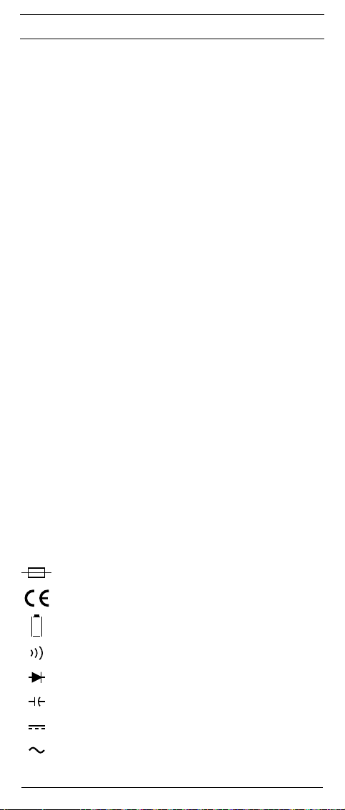
F
Notice d’emploi
BENNING MM 5-1/ MM 5-2
Multimètre numérique pour
- mesure de tension continue
- mesure de tension alternative
- mesure de courant continu (BENNING MM 5-2)
- mesure de courant alternatif (BENNING MM 5-2)
- mesure de résistance
- contrôle de diodes
- contrôle de continuité
- mesure de capacité
- mesure de fréquence
- mesure de température (BENNING MM 5-2)
Contenu
1. Remarques à l’attention de l’utilisateur
2. Consignes de sécurité
3. Volume de la livraison
4. Description de l’appareil
5. Indications générales
6. Conditions d’environnement
7. Indication des valeurs électriques
8. Mesure avec le BENNING MM 5-1/ MM 5-2
9. Entretien
10. Utilisation du cadre de protection en caoutchouc
11. Données techniques des accessoires de mesure.
12. Information sur l’environnement
1. Remarques à l’attention de l’utilisateur
Cette notice d’emploi s’adresse
- aux électriciens et
- aux personnes formées dans le domaine électrotechnique
Le BENNING MM 5-1/ MM 5-2 est conçu pour procéder à des mesures dans un
environnement sec et ne doit pas être utilisé dans des circuits électriques dont
la tension nominale est supérieure à 600 V CC/ CA (pour plus d’informations, se
reporter à la section 6 « Conditions d’environnement »).
Les symboles suivants sont utilisés dans la notice d’emploi et sur le
BENNING MM 5-1/ MM 5-2:
Attention ! Danger électrique !
Se trouve devant les remarques devant être respectées afin d‘éviter
tout risque pour les personnes.
Attention ! Se conformer à la documentation !
Ce symbole indique qu‘il faut tenir compte des remarques contenues
dans cette notice d‘emploi pour éviter les risques.
Ce symbole sur le BENNING MM 5-1/ MM 5-2 signifie que le
BENNING MM 5-1/ MM 5-2 est doté d’une double isolation (classe
de protection II).
Ce symbole sur le BENNING MM 5-2 indique qu’il y a des fusibles
intégrés.
Ce symbole sur le contrôleur BENNING MM 5-1/ MM 5-2 signifie que
le BENNING MM 5-1/ MM 5-2 est conforme aux directives de l‘UE.
Ce symbole apparaît sur l’affichage, indiquant qu’une batterie est
déchargée.
Ce symbole caractérise la plage « Contrôle de continuité ».
Le ronfleur émet un signal acoustique indiquant le résultat.
Ce symbole caractérise la plage « Contrôle de diodes ».
Ce symbole caractérise la plage « Mesure de capacité ».
(CC) tension continue ou courant continu
(CA) tension alternative ou courant alternatif
Terre (tension à la terre)
30
10/ 2015
BENNING MM 5-1/ 5-2
Page 30

F
2. Consignes de sécurité
Cet appareil a été fabriqué et contrôlé conformément à
DIN VDE 0411 Partie 1/EN 61010-1
DIN VDE 0411 Partiel 2-033/EN 61010-2-033
DIN VDE 0411 Partiel 031/EN 61010-031
et a quitté les ateliers de production dans un état technique parfait.
Pour conserver cet état et garantir un service sans risques, l’utilisateur doit se
conformer aux remarques et aux avertissements contenus dans cette notice
d’utilisation. Un maniement incorrect de l‘appareil et la non observation des avertissements pourraient provoquer des blessures graves ou danger de mort !
Soyez prudents si vous travaillez avec les conducteurs
denudés ou avec des lignes principales. Il y a le risque d‘un
électrochoc très dangereux au toucher de.
Le BENNING MM 5-1/ MM 5-2 doit être utilisé uniquement dans
des circuits électriques de la catégorie de protection contre
les surtensions III avec des conducteurs de max. 600 V ou
de catégorie de protection contre les surtensions IV avec des
conducteurs de max. 300 V à la terre.
Utiliser uniquement des câbles de mesure approprié pour cela.
Pour les mesures au sein de la catégorie de mesure III ou de
la catégorie de mesure IV, la partie conductrice saillante doit
avoir une pointe de contact sur les câbles de mesure pas plus
longue que 4 mm.
Avant les mesures au sein de la catégorie de mesure III et de la
catégorie de mesure IV, les capuchons joints au kit et signalés
par CAT III et CAT IV doivent être placés sur les pointes de
contact. Cette mesure est pour protéger l’utilisateur.
Veuillez noter que les travaux au niveau d‘éléments et d‘installations conducteurs de tension sont toujours dangereux. Déjà
les tensions de 30 V CA et 60 V CC peuvent être mortelles.
Assurez-vous, avant chaque mise en marche, que l‘appareil et
les câbles ne sont pas détériorés.
Si l’on considère que l’utilisation sans risques n’est plus possible, il faut mettre
l’appareil hors service et le protéger contre toute utilisation involontaire.
Une utilisation sans risques n’est plus possible
-
quand l’appareil ou les câbles de mesure présentent des détériorations visibles,
- quand l’appareil ne fonctionne plus,
- après un stockage prolongé dans de mauvaises conditions,
- après des conditions difficiles de transport,
- si l’appareil ou les câbles de mesure sont mouillés,
Pour exclure tout danger,
- ne touchez pas les parties dénudées des câbles de mesure
au niveau des pointes de mesure,
- raccordez les câbles de mesure aux douilles de mesure
repérées correspondantes du multimètre
Nettoyage :
Nettoyez le contrôleur régulièrement avec un chiffon sec et
un détergent. N‘utilisez jamais des produits de polissage ou
des solvants.
3. Volume de la livraison
Le volume de la livraison du BENNING MM 5-1/ MM 5-2 est composé de :
3.1 un BENNING MM 5-1/ MM 5-2,
3.2 un câble de mesure de sécurité, rouge (L = 1,4 m),
3.3 un câble de mesure de sécurité, noir (L = 1,4 m),
3.4 une sonde de température type K, (BENNING MM 5-2)
3.5 un cadre protecteur en caoutchouc avec support magnétique
3.6 une sacoche protectrice compacte,
3.7 deux piles 1,5 V du type R3 sont intégrées dans l‘appareil,
3.8 un fusible est intégré initialement dans l‘appareil (BENNING MM 5-2),
3.9 une notice d’emploi.
31
10/ 2015
BENNING MM 5-1/ 5-2
Page 31

F
Note relative aux accessoires optionnels :
- Capteur de température (type K) fait de tuyau V4A
Application : capteur à piquer pour les matières plastiques souples, liquides,
gaz et l‘air
Plage de mesure : - 196 °C à + 800 °C
Dimensions : longueur = 210 mm, longueur de tuyau = 120 mm, diamètre de
tuyau = 3 mm, V4A (réf. 044121)
Remarque sur les pièces d’usure:
- Le BENNING MM 5-2 contient des fusibles de protection contre la surcharge:
un fusible à courant nominal de 15 A à action instantanée (600 V), 50 kA, D =
10,3 mm, L = 38,1 mm (réf. 10149447).
- L‘appareil BENNING MM 5-1/ MM 5-2 est alimenté par deux piles 1,5 V du
type R3 intégrées (IEC LR 03).
- Les câbles de mesure de sécurité (accessoires contrôlés) mentionnés ci-
dessus correspondent à CAT III 1000 V/ CAT IV 600 V et sont homologués
pour un courant de 10 A.
4. Description de l’appareil
voir fig. 1 : panneau avant de l’appareil
La description des éléments et indicateurs de commande représentés à la Fig.
1 est la suivante :
indicateur numérique pour la valeur mesurée et affichage du dépassement
de plage,
indicateur de polarité,
indicateur de pile,
4
Touche de fonction (bleue),
5
Touche VoltSensor, afin de déterminer une tension AC par rapport à la
terre,
6
Touche « Δ/PEAK », fonction de valeur relative ou mémorisation de la
valeur de crête
7
touche Smart HOLD,
8
touche (jaune), éclairage de l’affichage,
9
commutateur rotatif, sert à sélectionner la fonction,
douille (positive1), pour V, Ω, , Hz (+) (BENNING MM 5-1) ou pour V, Ω,
, Hz, μA, ,(BENNING MM 5-2)
douille COM, douille commune pour mesure de courant, tension, résis-
tance, fréquence, température, capacité, contrôle de continuité et de diodes,
L
douille (positive), pour plage de 10 A, pour courants jusqu’à 10 A,
M
cadre de protection en caoutchouc
N
LED (rouge) pour l’indicateur de tension
1) L’indicateur automatique de polarité pour tension continue et courant continu s’y rapporte ici.
5. Indications générales
5.1 Indications générales sur le multimètre
5.1.1 L’indicateur numérique est un affichage à cristaux liquides 1 à 4 chiffres
de 16 mm de hauteur et à virgule décimale. La plus grande valeur affichable est 6000.
5.1.2 L’indicateur de polarité agit automatiquement. Seule la polarité oppo-
sée à la définition de la douille est affichée avec « - ».
5.1.3 Le dépassement de plage est indiquée par « OL » ou « -OL » et, partiel-
lement, par un signal acoustique.
Attention: pas d’affichage et d’avertissement en cas de surcharge!
5.1.4 Le commutateur rotatif 9 sert à sélectionner la fonction de mesure. La
sélection de la plage de mesure s’effectue automatiquement.
5.1.5 Touche « VoltSensor » 5: La fonction de l’indicateur de tension sert à
localiser des tensions alternatives par rapport à la terre (voir chapitre
8.9).
5.1.6 En appuyant sur la touche « Δ/PEAK » 6 (fonction de valeur relative),
la valeur affichée actuelle est mémorisée et la différence (offset) entre
la valeur mesurée mémorisée et les valeurs mesurées suivantes est
affichée. Appuyez sur la touche «Δ/PEAK » 6 pour 2 secondes afin
d’activer la fonction « PEAK » (mémorisation de la valeur de crête). La
fonction « PEAK » permet de saisir et de mémoriser la valeur maximale /
la valeur de crête positive et négative (> 1 ms) en mode mV, V AC/ DC et
mA, A AC/ DC. Appuyez sur la touche afin d’appeler les valeurs Pmax,
Pmin ainsi que la valeur mesurée actuelle (Pmax, Pmin). En appuyant
sur la touche pour 2 secondes environ, il est possible de retourner au
mode normal.
5.1.7 Mémorisation de la valeur mesurée « Smart HOLD » : le résultat de la
mesure est mémorisé quand on appuie sur la touche « Smart HOLD »
. Simultanément, le symbole « HOLD » apparaît sur l’affichage 1. Si
la mesure augmente de 50 chiffres au delà de la valeur mémorisée, le
32
10/ 2015
BENNING MM 5-1/ 5-2
Page 32

F
changement de valeur de mesure est affiché par un écran clignotant et
par un signal acoustique. (les changements des valeurs mesurées entre
les tensions/ courants AC et DC ne seront pas détectés).
5.1.8 La touche jaune 8 sert à allumer l’éclairage de l’écran. L’appareil est
mis hors service automatiquement après 2 minutes ou en appuyant
sur la touche encore une fois. Il est possible de désactiver l’arrêt automatique en appuyant sur la touche (bleue) 8 et en allumant l’appareil
BENNING MM 5-2 de la position « OFF » en même temps.
5.1.9 Appuyez sur la touche de fonction (bleue) 4 afin de sélectionner la
fonction secondaire ou troisième de la position du commutateur rotatif.
Position du
commutateur
Hz
Fonction
► Hz
Ω ► ►
5.1.10 Le taux nominal de mesure du BENNING MM 5-1/ MM 5-2 est de 2
mesures par seconde pour l’indicateur numérique.
5.1.11 Le BENNING MM 5-1/ MM 5-2 est mis en marche et éteint par le com-
mutateur rotatif . Position d’arrêt « OFF ».
5.1.12
Le BENNING MM 5-1/ MM 5-2 s’arrête automatiquement au bout de 20
minutes (APO, Auto-Power-Off). L’appareil peut être rallumé en actionnant
une touche quelconque. Il est possible de désactiver l’arrêt automatique
en appuyant sur la touche de fonction (bleue) 4 et en allumant l’appareil
BENNING MM 5-1/ MM 5-2 de la position « OFF » en même temps.
5.1.13 Contrôlez les segments de l’affichage numérique en appuyant
sur la touche « Smart HOLD » 7 et en allumant l’appareil
BENNING MM 5-1/ MM 5-2 de la position « OFF » en même temps.
5.1.14 Coefficient de température de la valeur mesurée : 0,1 x (précision de
mesure indiquée)/ °C < 18 °C ou > 28 °C, par rapport à la valeur avec
la température de référence de 23 °C.
5.1.15 L‘appareil BENNING MM 5-1/ MM 5-2 est alimenté par deux piles 1,5 V
du type R3 intégrées (IEC LR 03).
5.1.16 L’affichage de la batterie 3 indique en permanence la capacité de
batterie restante par au maximum 3 segments.
Dès que tous les segments dans le symbole batterie s’éteignent
et que le symbole batterie clignote, échangez immédiatement la
batterie contre une nouvelle batterie afin d’éviter des mesures
incorrectes qui mettent les personnes en danger.
5.1.17 La durée de vie d’une pile est d’environ 300 heures (batterie alcaline).
5.1.18 Dimensions de l’appareil :
(L x B x H) = 138 x 68 x 30 mm sans cadre de protection en caoutchouc
(L x B x H) = 150 x 77 x 44 mm avec cadre de protection en caoutchouc
Poids de l’appareil :
180 g sans cadre de protection en caoutchouc
310 g avec cadre de protection en caoutchouc
5.1.19 Les câbles de mesure de sécurité livrés conviennent expressément à la
tension nominale et le courant nominal du BENNING MM 5-1/ MM 5-2.
5.1.20 Le BENNING MM 5-1/ MM 5-2 est protégé par un cadre de protection
en caoutchouc M contre les détériorations mécaniques. Le cadre protecteur en caoutchouc M permet de poser l’appareil BENNING MM 5-1/
BENNING MM 5-2 pendant les mesures ou de l’attacher au moyen de
l’aimant intégré.
6. Conditions d’environnement
- Le BENNING MM 5-1/ MM 5-2 est conçu pour effectuer des mesures dans
un environnement sec,
- hauteur barométrique lors des mesures : maximum 2000 m,
- catégorie de surtension/catégorie d’installation : IEC 60664/ IEC 61010- 1 →
600 V catégorie III; 300 V catégorie IV,
- degré d’encrassement : 2,
- type de protection: IP 30 (DIN VDE 0470-1 IEC/ EN 60529).
IP 30 signifie: protection contre l’accès aux composants dangereux et
protection contre les impuretés solides > 2,5 mm de diamètre, (3 - premier
33
10/ 2015
BENNING MM 5-1/ 5-2
► ► Hz
°C ► °F
Page 33

F
indice). Aucune protection contre l’eau, (0 - second indice).
- température de travail et humidité relative de l’air :
avec une température de travail de 0 °C à 30 °C :
humidité relative de l’air inférieure à 80 %,
avec une température de travail de 30 °C à 40 °C :
humidité relative de l’air inférieure à 75 %,
avec une température de travail de 40 °C à 50 °C :
humidité relative de l’air inférieure à 45 %,
- température de stockage : le BENNING MM 5-1/ MM 5-2 peut être stocké à
des températures comprises entre - 20 °C et + 60 °C (humidité de l’air 0 à
80 %). Pour cela, il faut retirer la pile de l’appareil.
7. Indication des valeurs électriques
Remarque : La précision de mesure est indiquée en tant que somme
- d’une proportion relative de la valeur mesurée et
- d’un nombre de chiffres (c.-à-d. les chiffres de la dernière position).
Cette précision de mesure est valable pour des températures entre 18 °C et
28 °C et une humidité relative de l’air inférieure à 80 %.
La valeur mesu rée est obtenue et affichée comme valeur effective (TRUE RMS,
couplage AC). Les signaux rectangulaires (> 100 Hz) ne sont pas spécifiés.
Quand la forme des courbes n’est pas sinusoïdale, la valeur affichée est imprécise. Il en résulte une erreur supplémentaire pour les facteurs de crête suivants :
facteur de crête de 1,0 à 2,0 erreur supplémentaire + 1,0 %
facteur de crête de 2,0 à 2,5 erreur supplémentaire + 2,5 %
facteur de crête de 2,5 à 3,0 erreur supplémentaire + 4,0 % (valable jusqu’à
4000 chiffres)
7.1 Plages de tensions continues DC
La résistance d’entrée est de 10 MΩ.
Protection contre la surcharge: 600 V
Plage de
mesure
6,000 V 6,600 V 0,001 V ± (0,5 % de la valeur mesurée + 3 chiffres)
60,00 V 66,00 V 0,01 V ± (0,5 % de la valeur mesurée + 3 chiffres)
600,0 V 660,0 V 0,1 V ± (0,5 % de la valeur mesurée + 3 chiffres)
7.1.1 Plages de tensions continues mV DC
La résistance d’entrée est de 10 MΩ.
Protection contre la surcharge: 600 V
Plage de
mesure
600,0 mV 660,0 mV 0,1 mV ± (0,5 % de la valeur mesurée + 5 chiffres)
7.2 Plages de tensions alternatives AC
La résistance d’entrée est de 10 MΩ en parallèle à < 100 pF.
Protection contre la surcharge: 600 V
Plage de
mesure
600,0 mV 660,0 mV 0,1 mV ± (2,5 % de la valeur mesurée + 5 chiffres)*
6,000 V 6,600 V 0,001 V ± (1,0 % de la valeur mesurée + 3 chiffres)
60,00 V 66,00 V 0,01 V ± (1,0 % de la valeur mesurée + 3 chiffres)
600,0 V 660,0 V 0,1 V ± (1,0 % de la valeur mesurée + 3 chiffres)
* Plage de mesure à partir de ≥ 2,0 mV
7.3 Plages de courant continu DC (BENNING MM 5-2)
Protection contre la surcharge :
-
Temps de mesure maximal :
- 3 minutes avec 10 A (pause > 20 minutes)
- 15 secondes avec 20 A (pause > 20 minutes)
Plage de
mesure
10 A 20,00 A 0,01 A ± (1,5 % de la valeur mesurée + 3 chiffres)
34
10/ 2015
Indication de
surcharge (« OL »)
Indication de
surcharge (« OL »)
Indication de
surcharge (« OL »)
fusible de 15 A (600 V AC/ DC), 50 kA, à action instantanée à l’entrée 10 A
Indication de
surcharge (« OL »)
6 A 6,600 A 0,001 A ± (1,5 % de la valeur mesurée + 3 chiffres)
BENNING MM 5-1/ 5-2
AC/DC
Résolution Précision de mesure
AC/DC
Résolution Précision de mesure
AC/DC
Résolution
Résolution Précision de mesure
Précision de mesure dans la plage de
fréquence 45 Hz - 500 Hz (sinusoïdal)
,
Page 34

F
7.3.1 Plages de courant continu µA DC (BENNING MM 5-2)
La résistance d’entrée est de ca. 3 kΩ.
Protection contre la surcharge: 600 V
Plage de
mesure
Indication de
surcharge (« OL »)
400,0 µA 440,0 µA 0,1 µA ± (0,9 % de la valeur mesurée + 5 chiffres)
4000 µA 4400 µA 1 µA ± (0,9 % de la valeur mesurée + 5 chiffres)
7.4 Plages de courants alternatifs AC (BENNING MM 5-2)
Protection contre la surcharge :
-
fusible de 15 A (600 V AC/ DC), 50 kA, à action instantanée à l’entrée 10 A,
Temps de mesure maximal :
- 3 minutes avec 10 A (pause > 20 minutes)
- 15 secondes avec 20 A (pause > 20 minutes)
Plage de
mesure
Indication de
surcharge (« OL »)
6 A 6,600 A 0,001 A ± (1,5 % de la valeur mesurée + 5 chiffres)*
10 A 20,00 A 0,01 A ± (1,5 % de la valeur mesurée + 5 chiffres)
* Plage de mesure à partir de ≥ 20 mA
7.5 Plages de résistances
Protection contre la surcharge: 600 V
Plage de
mesure
Indication de
surcharge (« OL »)
600,0 Ω 660,0 Ω 0,1 Ω
6,000 kΩ 6,600 kΩ 0,001 kΩ
60,00 kΩ 66,00 kΩ 0,01 kΩ
600,0 kΩ 660,0 kΩ 0,1 kΩ
6,000 MΩ 6,000 MΩ 0,001 MΩ
40,00 MΩ 40,00 MΩ 0,01 MΩ
* Les valeurs mesurées > 10 MΩ peuvent entraîner un changement des
valeurs affichées (max. ± 50 chiffres).
7.6 Contrôle de diodes
Protection contre la surcharge: 600 V
Tension à vide: 1,8 V
Plage de
mesure
Indication de
surcharge (« OL »)
1,500 V 1,550 V 0,001 V ± (1,0 %
7.7 Contrôle de continuité
Protection contre la surcharge : 600 V
Le ronfleur incorporé retentit quand il y a une résistance inférieure à 30 Ω à 200
Ω. Le signal acoustique s‘arrête en cas d‘une résistance supérieure à 200 Ω.
Plage de
mesure
Indication de
surcharge (« OL »)
600,0 Ω 660,0 Ω 0,1 Ω ± (0,5 %
7.8 Plages de capacités
Conditions : décharger les condensateurs et les appliquer en fonction de la
Protection contre la surcharge: 600 V
Plage de
mesure
polarité indiquée.
Indication de
surcharge (« OL »)
50,00 nF 55,00 nF 0,01 nF ± (2,0 % de la valeur mesurée + 10 chiffres)
500,0 nF 550,0 nF 0,1 nF ± (2,0 % de la valeur mesurée + 5 chiffres)
5,000 µF 5,500 µF 0,001 µF ± (2,0 % de la valeur mesurée + 5 chiffres)
50,00 µF 55,00 µF 0,01 µF ± (2,0 % de la valeur mesurée + 5 chiffres)
500,0 µF 550,0 µF 0,1 µF ± (2,0 % de la valeur mesurée + 5 chiffres)
1000 µF 1100 µF 1 µF ± (2,0 % de la valeur mesurée + 5 chiffres)
35
10/ 2015
BENNING MM 5-1/ 5-2
AC/DC
Résolution Précision de mesure
Résolution
Précision de mesure dans la plage
de fréquence 45 Hz - 500 Hz (sinusoïdal)
AC/ DC
Résolution Précision de mesure
± (0,5 % de la valeur mesurée + 5 chiffres)
± (0,5 % de la valeur mesurée + 2 chiffres)
± (0,5 % de la valeur mesurée + 2 chiffres)
± (0,5 % de la valeur mesurée + 2 chiffres)
± (0,5 % de la valeur mesurée + 2 chiffres)
± (1,0 % de la valeur mesurée + 5 chiffres)
AC/ DC
Résolution Précision de mesure
de la valeur mesurée + 3 chiffres)
AC/ DC
Résolution Précision de mesure
de la valeur mesurée + 5 chiffres)
AC/ DC
Résolution Précision de mesure
*
Page 35

F
7.9 Plages de fréquence
Protection contre la surcharge: 600 V
Plage de
mesure
100,00 Hz 100,00 Hz 0,01 Hz ± (0,2 % de la valeur mesurée + 2 chiffres)
1000,0 Hz 1000,0 Hz 0,1 Hz ± (0,2 % de la valeur mesurée + 2 chiffres)
10,000 kHz 10,000 kHz 0,001 kHz ± (0,2 % de la valeur mesurée + 2 chiffres)
50,00 kHz 50,00 kHz 0,01 kHz ± (0,2 % de la valeur mesurée + 2 chiffres)
Fréquence minimum: 10 Hz
Sensibilité minimum: > 4 V
> 20 V
> 0,6 A
7.10 Plages de températures °C/ °F (BENNING MM 5-2)
Protection contre la surcharge : 600 V
Plage de mesure
-40 °C - +400 °C - 44 °C - +440 °C 0,1 °C ± (1 % de la valeur mesurée + 20 chiffres)
-40 °F - +752 °F - 44 °F - +827,2 °F 0,1 °F ± (1 % de la valeur mesurée + 36 chiffres)
* Il faut additionner la précision de mesure du capteur de température (type K)
à la précision de mesure indiquée.
Capteur de température à fil du type K:
Plage de mesure : - 60 °C à 200 °C
Précision de mesure maximum: ± 2 °C
La précision de mesure est valable pour les températures ambiantes stables
< ± 1 °C. Après un changement de la température ambiante de ± 2 °C, les indications de précision de mesure seront valables après deux heures.
7.11 Fonction « PEAK HOLD » pour AC V / AC A
Ajoutez ± 150 chiffres à la précision de mesure indiquée.
Les signaux rectangulaires ne sont pas spécifiés.
8. Mesurer avec le BENNING MM 5-1/ MM 5-2
8.1 Préparation des mesures
Utilisez et stockez le BENNING MM 5-1/ MM 5-2 uniquement dans les conditions spécifiées de température de travail et de stockage, évitez l’exposition
prolongée aux rayons du soleil.
- Contrôlez les indications de tension nominale et de courant nominal des
câbles de mesure de sécurité. La tension nominale et le courant nominal des
câbles de mesure de sécurité livrés avec l’appareil correspondent à ceux du
BENNING MM 5-1/ MM 5-2.
- Contrôlez l’isolation des câbles de mesure de sécurité. En cas de détériora-
tion de l’isolation, il faudra remplacer immédiatement les câbles de mesure
de sécurité.
- Contrôlez la continuité des câbles de mesure de sécurité. En cas de rupture
du conducteur des câbles de mesure de sécurité, il faudra remplacer immé-
diatement les câbles de mesure de sécurité.
- Avant de sélectionner une autre fonction avec le commutateur rotatif , faut
retirer les câbles de mesure de sécurité du point de mesure.
-
Les fortes sources de parasites à proximité du BENNING MM 5-1/ MM 5-2
peuvent entraîner l’instabilité de l’affichage et provoquer des mesures erronées.
8.2 Mesure de tension et de courant
La tension maximum pouvant être appliquée aux douilles
- douille COM K
- douille pour V, Ω, , Hz (+) (BENNING MM 5-1) ou pour V, Ω, , Hz, μA,
- douille pour plage de 10 A L (BENNING MM 5-2)
du BENNING MM 5-1/ MM 5-2 contre la terre est de 600 V CAT III.
8.2.1 Mesure de tension
-
Avec le commutateur rotatif 9, sélectionner la fonction souhaitée ( , ,
sur le BENNING MM 5-1/ MM 5-2.
- Mettez en contact le câble de mesure de sécurité noir avec la douille COM
36
10/ 2015
Indication de
surcharge (« OL »)
pour VAC (10 Hz - 10 kHz)
eff
pour VAC (10 kHz - 50 kHz)
eff
pour AAC (10 Hz - 50 kHz)
eff
Indication de
surcharge (« OL »)
Tenez compte de la tension maximum contre le potentiel à la
terre ! Risque d’électrocution !
(BENNING MM 5-2)
BENNING MM 5-1/ 5-2
AC/ DC
Résolution Précision de mesure
AC/ DC
Résolution Précision de mesure
)
Page 36

F
du BENNING MM 5-1/ MM 5-2.
- Mettez en contact le câble de mesure de sécurité rouge avec la douille
du BENNING MM 5-1/ MM 5-2.
- Mettez en contact les câbles de mesure de sécurité avec les points
de mesure, lisez la valeur mesurée sur l’indicateur numérique du
BENNING MM 5-1/ MM 5-2.
voir fig. 2 : Mesure de tension continue
voir fig. 3 : Mesure de tension alternative
8.2.2 Mesure de courant (BENNING MM 5-2)
- Avec le commutateur rotatif , sélectionner la plage et la fonction souhai-
tées (A AC/DC ou µA DC) du BENNING MM 5-2.
- Mettez en contact le câble de mesure de sécurité noir avec la douille COM
du BENNING MM MM 5-2.
- Reliez le câble de mesure de sécurité rouge à la douille pour la plage A
(jusqu’à 10 A AC/DC) ou à la douille pour V, Ω, Hz, µA DC, , (jusqu’à
4000 μA DC) de l’appareil BENNING MM 5-2.
- Dans la fonction (A AC/DC), sélectionnez le type de courant à mesurer
(courant continu DC ou courant alternatif AC) au moyen de la touche bleue
4
de l’appareil BENNING MM 5-2.
- Mettez en contact les câbles de mesure de sécurité avec les points de mesure,
lisez la valeur mesurée sur l’indicateur numérique du BENNING MM 5-2.
voir fig. 4 : Mesure de courant continu
voir fig. 5 : Mesure de courant alternatif
8.3 Mesure de résistance
- Avec le commutateur rotatif , sélectionner la fonction souhaitée (Ω, , )
du BENNING MM 5-1/ MM 5-2.
- Mettez en contact le câble de mesure de sécurité noir avec la douille COM
du BENNING MM 5-1/ MM 5-2.
- Mettez en contact le câble de mesure de sécurité rouge avec la douille
du BENNING MM 5-1/ MM 5-2.
- Mettez en contact les câbles de mesure de sécurité avec les points
de mesure, lisez la valeur mesurée sur l’indicateur numérique du
BENNING MM 5-1/ MM 5-2.
voir fig. 6 : Mesure de résistance
8.4 Contrôle de diodes
- Avec le commutateur rotatif , sélectionner la fonction souhaitée (Ω, , )
du BENNING MM 5-1/ MM 5-2.
- Avec la touche (bleue) du BENNING MM 5-1/ MM 5-2, commuter
(appuyez deux fois) sur le contrôle de diodes ( ).
- Mettez en contact le câble de mesure de sécurité noir avec la douille COM
du BENNING MM 5-1/ MM 5-2.
- Mettez en contact le câble de mesure de sécurité rouge avec la douille pour
du BENNING MM 5-1/ MM 5-2.
- Mettez en contact les câbles de mesure de sécurité avec les connexions
pour diodes, lisez la valeur mesurée sur l’indicateur numérique du
BENNING MM 5-1/ MM 5-2.
- Dans le cas d’une diode Si placée dans le sens normal du flux, la tension de
flux affichée est comprise entre 0,4 V et 0,8 V. L’affichage « 000 » indique
qu’il y a court-circuit dans la diode.
- Si l’appareil ne détecte pas une tension directe, il faut tout d’abord contrôler
la polarité de la diode. Si toujours aucune tension directe n’est affichée, la
tension directe de la diode est hors des limites de la mesure.
voir fig. 7 : Contrôle de diodes
8.5 Contrôle de continuité avec ronfleur et LED rouge
- Avec le commutateur rotatif , sélectionner la fonction souhaitée (Ω, , )
du BENNING MM 5-1/ MM 5-2.
- Avec la touche (bleue) 4 du BENNING MM 5-1/ MM 5-2, commuter
(appuyez deux fois) sur le contrôle de continuité ( ).
- Mettez en contact le câble de mesure de sécurité noir avec la douille COM
du BENNING MM 5-1/ MM 5-2.
- Mettez en contact le câble de mesure de sécurité rouge avec la douille
du BENNING MM 5-1/ MM 5-2.
- Mettez en contact les câbles de mesure de sécurité avec les points de
mesure. Si la résistance de ligne entre la douille COM et la douille est
inférieure à une valeur entre 30 Ω et 200 Ω, le ronfleur intégré de l’appareil
BENNING MM 5-1/ MM 5-2 émet un signal acoustique et la LED rouge N
s’allume.
voir fig. 8 : Contrôle de continuité avec ronfleur
L
37
10/ 2015
BENNING MM 5-1/ 5-2
Page 37

F
8.6 Mesure de capacité
Décharger entièrement les condensateurs avant de mesurer la
capacité ! Ne jamais appliquer de tension aux douilles de pour
mesure de capacité Il y a risque de détérioration de l’appareil.
Tout appareil détérioré présente un danger d’électrocution !
- Avec le commutateur rotatif , sélectionner la fonction souhaitée ( ) du
BENNING MM 5-1/ MM 5-2.
- Déterminez la polarité du condensateur et le décharger entièrement.
- Mettez en contact le câble de mesure de sécurité noir avec la douille COM
du BENNING MM 5-1/ MM 5-2.
- Mettez en contact le câble de mesure de sécurité rouge avec la douille
du BENNING MM 5-1/ MM 5-2.
- Mettez en contact les câbles de mesure de sécurité avec le condensateur
en fonction de sa polarité, lisez la valeur mesurée sur l’indicateur numérique
du BENNING MM 5-1/ MM 5-2.
voir fig. 9 : Mesure de capacité
8.7 Mesure de fréquence
- Sélectionnez au moyen du commutateur rotatif 9 la fonction souhaitée (Hz)
sur l’appareil BENNING MM 5-1 ou la fonction ( Hz ou A AC/DC Hz) sur
l’appareil BENNING MM 5-2.
- Mettez en contact le câble de mesure de sécurité noir avec la douille COM
du BENNING MM 5-1/ MM 5-2.
- Afin de mesurer la fréquence dans la plage de tension, reliez
le câble de mesure de sécurité rouge à la douille de l’appareil
BENNING MM 5-1/ MM 5-2 et appuyez sur la touche bleue 4 de l’appareil
BENNING MM 5-2 afin de passer à la mesure de fréquence (Hz).
- Afin de mesurer la fréquence dans la plage de courant, reliez le câble de
mesure de sécurité rouge à la douille L de l’appareil BENNING MM 5-2
et appuyez sur la touche bleue 4 (appuyez deux fois) afin de passer à la
mesure de fréquence (Hz).
- Tenez compte de la sensibilité minimum pour mesures de fréquence avec le
BENNING MM 5-1/ MM 5-2 !
- Mettez en contact les câbles de mesure de sécurité avec les points de
mesure, lisez la valeur mesurée sur l’indicateur numérique du
BENNING MM 5-1/ MM 5-2.
voir fig. 10 : Mesure de fréquence
8.8 Mesure de température (BENNING MM 5-2)
- Avec le commutateur rotatif 9, sélectionner la fonction souhaitée ( ) du
BENNING MM 5-2.
- Appuyez sur la touche bleue 4 afin de passer en mode °F ou °C.
- Reliez le capteur de température (type K) à la douille COM et à la douille
en respectant la polarité correcte.
- Placez le point de contact (extrémité du câble de la sonde) sur l’emplace-
ment à mesurer. Lisez la valeur mesurée sur l’indicateur numérique du
BENNING MM 5-2.
voir fig. 11 : Mesure de température
8.9 Indicateur de tension
La fonction de l'indicateur de tension ne sert pas à déterminer
l'absence de tension. Même sans l'émission d'un signal
acoustique ou optique, il est possible qu'une tension de
contact dangereuse soit présente. Danger électrique !
La fonction de l‘indicateur de tension est possible dans chaque position du commutateur rotatif (sauf position du commutateur « OFF »). Iil n‘est pas nécessaire
d‘utiliser des câbles de mesure en tant qu‘indicateur de tension (saisie sans
contact d‘un champ alternatif). Le capteur récepteur se trouve sur le côté face de
l’appareil BENNING MM 5-1/ MM 5-2. Appuyez sur la touche « VoltSensor » 5
afin de faire disparaître l’affichage des valeurs mesurées. Au cas où une tension
de phase serait localisée, la LED rouge N s’allume et le symbole apparaît sur
l’affichage numérique. Un affichage n‘est effectué qu‘en réseaux à courant alternatif mis à la terre ! Il est également possible de déterminer la phase au moyen
d‘un câble de mesure unipolaire.
Tuyau pratique :
Les interruptions (ruptures de câble) des câbles dénudés comme par ex. les
tambours de câble, les chaînes de lumières etc. peuvent être tracées du point
d‘alimentation jusqu‘au point de l‘interruption.
Plage fonctionnelle : ≥ 230 V
Voir figure 12: Indicateur de tension
38
10/ 2015
BENNING MM 5-1/ 5-2
Page 38

F
8.9.1 Test de phase
- Mettez en contact le câble de mesure de sécurité rouge avec la douille
de l‘appareil BENNING MM 5-1/ MM 5-2.
- Mettez en contact le câble de mesure de sécurité avec le composant du
point de mesure et appuyez sur la touche « VoltSensor » 5.
- Au cas où la LED rouge N s’allumerait et le symbole serait affiché sur
l’affichage numérique, la phase d’une tension alternative mise à la terre est
présente sur ce point de mesure (composant).
9. Entretien
Avant d’ouvrir le BENNING MM 5-1/ MM 5-2, il faut absolument
le mettre hors tension ! Risque d’électrocution !
Seuls des spécialistes devant prendre des mesures particulières pour prévenir les accidents sont autorisés à travailler avec le
BENNING MM 5-1/ MM 5-2 quand celui-ci est ouvert et sous tension.
Procédez de la manière suivante pour mettre le BENNING MM 5-1/ MM 5-2 hors
tension avant de l’ouvrir :
- Retirez d’abord les deux câbles de mesure de sécurité de l’objet à mesurer.
- Retirez ensuite les deux câbles de mesure de sécurité du
BENNING MM 5-1/ MM 5-2.
- Amenez le commutateur rotatif 9 sur la position « OFF ».
9.1 Rangement sûr de l’appareil
Dans certaines conditions, la sécurité de manipulation du
BENNING MM 5-1/ MM 5-2 n’est plus donnée ; par exemple, en cas :
- de détériorations visibles du boîtier,
- d’erreurs de mesure,
- de dommages décelables résultant d’un stockage prolongé dans des condi-
tions inacceptables et
-
de dommages décelables résultant d’une grande sollicitation lors du transport.
Dans ces cas, il faut couper immédiatement l’alimentation du
BENNING MM 5-1/ MM 5-2, le retirer des points de mesure et le ranger de
manière sûre afin qu’il ne puisse pas être réutilisé.
9.2 Nettoyage
Nettoyer l’extérieur du boîtier avec un chiffon propre (seule exception : chiffons
spéciaux de nettoyage). N’employer ni solvants ni produits récurrents pour nettoyer l’appareil. Il faut absolument veiller à ce que de l’électrolyte ne se répande
ni ne salisse le logement et les contacts des piles.
En cas de présence d’électrolyte ou de dépôts blancs au niveau des piles ou du
logement, les retirer à l’aide d’un chiffon sec.
9.3 Remplacement de la pile
Avant d’ouvrir le BENNING MM 5-1/ MM 5-2, il faut absolument
le mettre hors tension ! Risque d’électrocution !
L‘appareil BENNING MM 5-1/ MM 5-2 est alimenté par deux piles 1,5 V du
type R3. Il est nécessaire de remplacer les piles (voir figure 13) dès que tous
les segments du symbole de pile 3 sont éteints et le symbole de pile clignote.
Remplacez la pile de la manière suivante :
- Retirez les câbles de mesure de sécurité du circuit de mesure.
- Retirez les câbles de mesure de sécurité du BENNING MM 5-1/ MM 5-2.
- Amenez le commutateur rotatif sur la position « OFF ».
- Retirez le cadre de protection en caoutchouc M du BENNING MM 5-1/ MM 5-2.
- Posez le BENNING MM 5-1/ MM 5-2 sur le panneau avant et retirez la vis
du couvercle du boîtier.
-
Enlevez le couvercle du compartiment à piles de la partie inférieure de
l‘appareil.
- Enlevez les piles déchargées du compartiment à piles.
- Insérez les nouvelles piles dans le compartiment à piles en respectant la
- Introduisez le logement dans la partie inférieure et serrez la vis.
- Placez le BENNING MM 5-1/ MM 5-2 dans le cadre de protection en caout-
voir fig. 13 : Remplacement de la pile
39
10/ 2015
polarité correcte.
chouc M.
Contribuez à protéger l’environnement ! Ne jetez pas les piles
dans les ordures ménagères. Vous pouvez les porter à un
centre de collecte de piles usées ou de déchets spéciaux.
Veuillez vous renseigner auprès des autorités locales.
BENNING MM 5-1/ 5-2
Page 39

F
9.4 Remplacement des fusibles (BENNING MM 5-2)
Avant d’ouvrir le BENNING MM 5-2, il faut absolument le mettre
hors tension ! Risque d’électrocution !
Le BENNING MM 5-2 est protégé contre la surcharge par un fusible intégré (G
cartouche fusible) de 15 A à action instantanée (voir fig. 14)
Remplacez le fusible de la manière suivante :
- Retirez les câbles de mesure de sécurité du circuit de mesure.
- Retirez les câbles de mesure de sécurité du BENNING MM 5-2.
- Amenez le commutateur rotatif sur la position « OFF ».
- Retirez le cadre de protection en caoutchouc M du BENNING MM 5-2.
- Posez le BENNING MM 5-2 sur le panneau avant et retirez la vis du cou-
vercle du boîtier.
- Enlevez le couvercle du compartiment à piles de la partie inférieure de
l‘appareil.
Ne retirez aucune vis du circuit imprimé du BENNING MM 5-2.
- Enlevez les quatre vis extérieures (noires) de la partie inférieure du boîtier.
- Soulevez le fond du boîtier dans la partie inférieure et retirez-le dans la
partie supérieure du panneau avant.
- Soulevez hors du porte-fusible une extrémité du fusible défectueux.
- Retirez entièrement le fusible défectueux hors du porte-fusible.
- Placez un fusible neuf présentant le même courant nominal, la même carac-
téristique de déclenchement et les mêmes dimensions.
- Arrangez le fusible de manière à ce qu’il soit au centre du porte-fusible.
- Montez le fond du boîtier sur le panneau avant et placez les quatre vis.
- Introduisez le logement dans la partie inférieure et serrez la vis.
- Placez le BENNING MM 5-2 dans le cadre de protection en caoutchouc M.
voir fig. 14 : Remplacement des fusibles
9.5 Étalonnage
Benning garantie la conformité aux spécifications techniques et indications de
précision figurant dans ce mode d’emploi pendant la première année à partir
de la date de livraison.
Pour conserver la précision spécifiée des résultats de mesure, il faut faire
étalonner régulièrement l’appareil par notre service clients. Nous conseillons
de respecter un intervalle d’étalonnage d’un an. Envoyez, pour cela, l’appareil
à l’adresse suivante:
Benning Elektrotechnik & Elektronik GmbH & CO. KG
Service Center
Robert-Bosch-Str. 20
D - 46397 Bocholt
9.6 Pièces de rechange
Fusible F 15 A, 600 V, 50 kA, D = 10,3 mm, L = 38,1 mm, Réf. 10149447
10. Utilisation du cadre de protection en caoutchouc
- Vous pouvez ordonner les câbles de mesure de sécurité de telle sorte à les
enrouler autour du cadre de protection en caoutchouc M et à engager les
pointes des câbles dans le cadre de protection en caoutchouc M pour les
protéger (voir fig. 15).
- Vous pouvez ordonner un câble de mesure de sécurité sur le cadre
de protection en caoutchouc M de manière à ce que la pointe de
mesure soit libre pour être dirigée vers une pointe de mesure avec le
BENNING MM 5-1/ MM 5-2.
- L’étrier au dos du cadre de protection en caoutchouc M permet d’incliner (pour
en faciliter la lecture) le BENNING MM 5-1/ MM 5-2 (voir fig. 16).
- Le cadre protecteur en caoutchouc M est pourvu d’un aimant qui peut être
utilisé afin de pouvoir suspendre l’appareil.
voir fig. 15 : enroulement du câble de mesure de sécurité
voir fig. 16 : installation du BENNING MM 5-1/ MM 5-2
11. Données techniques des accessoires de mesure
- norme : EN61010-031
- calibre de tension maximum à la terre () et catégorie de mesure :
avec capuchon: 1000 V CAT III, 600 V CAT IV,
sans capuchon: 1000 V CAT II,
- calibre courant maximum : 10 A,
- classe de protection II (), isolement continu double ou renforcé,
- degré de contamination : 2,
40
10/ 2015
BENNING MM 5-1/ 5-2
Page 40

F
- longueur : 1.4m AWG18,
- conditions d’environnement :
hauteur barométrique maximum pour faire des mesures : 2000m,
température : 0°C à +50°C humidité : 50% à 80%
- Les câbles de mesure ne doivent être utilisés que s’ils ont un aspect irrépro-
chable et selon les conditions prescrites par le manuel d’utilisation, sinon la
protection prévue pourrait être détériorée.
- Jeter le câble si l’isolement est endommagée ou s’il y a une rupture entre le
câble et la prise.
- Ne pas toucher les pointes de contact nues. Ne tenir que par l’endroit appro-
prié à la préhension manuelle !
- Insérer les raccords coudés dans l’appareil de test ou de mesure.
12. Information sur l’environnement
Une fois le produit en fin de vie, veuillez le déposer dans un point de
recyclage approprié.
41
10/ 2015
BENNING MM 5-1/ 5-2
Page 41

E
Instrucciones de servicio
multímetro BENNING MM 5-1/ MM 5-2
Multímetro digital para
- Medición de tensión contínua
- Medición de tensión alterna
- Medición de corriente contínua (BENNING MM 5-2)
- Medición de corriente alterna (BENNING MM 5-2)
- Medición de resistencia
- Verificación de diodos
- Control de continuidad
- Medición de capacidad
- Medición de frecuencias
- Medición de temperaturas (BENNING MM 5-2)
Contenido
1. Instrucciones para el operario
2. Instrucciones de seguridad
3. Envergadura del suministro
4. Descripción
5. Generalidades
6. Condiciones ambientales
7. Datos eléctricos
8. Medir con el multímetro BENNING MM 5-1/ MM 5-2
9. Mantenimiento
10. Empleo del marco protector de goma
11. Datos técnicos de los accesorios de medida
12. Advertencia
1. Instrucciones para el operario
Estas instrucciones de operación están destinadas a
- personal especializado en electrotecnia y
- personas electrotécniamente instruidas
El multímetro BENNING MM 5-1/ MM 5-2 está previsto para empleo exclusivo
en ambiente seco. El equipo no puede ser empleado en circuitos con tensión
nominal superior a 600 V DC/ AC (para más detalles, ver sección 6, „Condiciones ambientales“.
En las Instrucciones de servicio y en el multímetro BENNING MM 5-1/ MM 5-2
se emplean los símbolos siguientes:
¡Peligro eléctrico!
Este símbolo aparece en avisos a observar para evitar peligros
para personas.
¡Cuidado, observar la documentación!
Este símbolo indica que hay que observar los avisos en estas
instrucciones de servicio, para evitar peligro.
Este símbolo en el multímetro BENNING MM 5-1/ MM 5-2 indica que
dispone de aislamiento protector (clase de protección II).
Este símbolo en el equipo BENNING MM 5-2 indica los fusibles
integrados.
Este símbolo en el multímetro BENNING MM 5-1/ MM 5-2 indica que
el BENNING MM 5-1/ MM 5-2 se ajustan a las directivas de la UE.
Este símbolo en el display indica una batería descargada.
Este símbolo marca la función de “control de continuidad”. El
vibrador sirve de señalización acústica del resultado.
Este símbolo marca la función de “verificación de diodos”.
Este símbolo marca la función de “control de capacidad“.
(DC) tensión contínua o corriente contínua.
(AC) tensión alterna o corriente alterna.
Tierra (potencial puesta a tierra).
42
10/ 2015
BENNING MM 5-1/ 5-2
Page 42

E
2. Instrucciones de seguridad
El equipo es fabricado conforme a la norma
DIN VDE 0411 parte 1/EN 61010-1
DIN VDE 0411 parte 2-033/EN 61010-2-033
DIN VDE 0411 parte 031/EN 61010-031
verificado, y salió de fábrica en perfecto estado de seguridad.
Para manener el equipo en este perfecto estado de seguridad y garantizar su
funcionamiento sin peligro, el usuario debe observar las informaciones y advertencias de peligros en este manual de servicio. La mala conducta y el descuido
de las advertencias que pueden conducir a lesiones graves o la muerte.
PELIGRO! Se debe tener estremo cuidado cuando se trabaja
con barras conductoras o líneas de red con tensión! El contacto
con líneas activas puede causar un shock eléctrico!
El BENNING MM 5-1/ MM 5-2 sólo está permitido para uso
en circuitos de corriente de la categoría de sobretensión III
con conductor frente a tierra máx. 600 V o de la categoría de
sobretensión IV con conductor frente a tierra máx. 300 V.
Utilice únicamente cables de medición adecuados para ello. En
las mediciones dentro de la categoría de medición III o de la
categoría de medición IV la pieza conductora saliente de una
punta de contacto de cable de medida no deberá tener una
longitud superior a los 4 mm.
Antes de realizar mediciones dentro de la categoría de medi ción
III y de la categoría de medición IV deberán colocarse las tapas
enchufables suministradas con el set, marcadas con CAT III
y CAT IV, en las puntas de contacto. Esta medida tiene como
finalidad la protección del usuario.
Tenga usted en cuenta que cualquier trabajo en partes e instalaciones bajo tensión eléctrica por principio son peligrosos.
Ya pueden suponer peligro de muerte para las personas las
tensiones a partir de 30 V AC y 60 V DC.
Ante cada puesta en servicio, usted debe verificar que el equipo
y las conducciones no muestren daños.
Cuando ha de suponerse que ya no queda garantizado el funcionamiento sin
peligro, hay que desactivar el equipo y asegurarlo para evitar su accionamiento
involuntario.
Se supone que ya no queda garantizado su funcionamiento sin peligro, cuando,
- el equipo o las conducciones de medición muestran daños visibles,
- cuando el equipo ya no funciona,
- tras un largo período de almacenamiento sin usarlo y bajo condiciones
desfavorables,
- tras haber sufrido esfuerzos debido al transporte,
- el aparato o los circuitos de medición están húmedos,
Para evitar peligros
- no tocar las conducciones de medición en las puntas de
medición al descubierto,
- enchufar las conducciones de medición en las
correspondientes hembrillas de medición marcadas
Limpieza:
Limpiar la superficie de la carcasa con un paño limpio y seco
(excepcionalmente con paños especiales de limpieza). No
aplique agentes disolventes o abrasivos para limpiar el equipo.
3. Envergadura del suministro
Forman parte del suministro del multímetro BENNING MM 5-1/ MM 5-2:
3.1 multímetro BENNING MM 5-1/ MM 5-2, una unidad
3.2 conducción protegida de medición, una unidad, color rojo (L = 1,4 m),
3.3 conducción protegida de medición, una unidad, color negro (L = 1,4 m),
3.4 sensor de temperatura tipo K, una unidad (BENNING MM 5-2)
3.5 marco protector de goma con soporte magnético, una unidad
3.6 bolsa compacta de protección, una unidad,
3.7 dos pilas 1,5 V tipo AAA, montadas en los multímetros,
3.8 un fusible par ensamble inicial está integrado en el multímetro
(BENNING MM 5-2),
43
10/ 2015
BENNING MM 5-1/ 5-2
Page 43

E
3.9 instrucciones de servicio, una unidad.
Nota accesorios opcionales:
- Sonda de temperature (tipo - K) fabricado de tubo V4A
aplicación: prueba de inserción para materiales plásticos blandos, líquidos,
gases y aire
rango de medida - 196 °C hasta + 800 °C
dimensiones: largo = 210 mm, longitude del tubo = 120 mm, diámetro del
tubo = 3 mm, V4A (a-no. 044121)
Piezas propensas al desgaste:
- El multímetro BENNING MM 5-2 se equipan con un fusible para protección
de sobrecargas:
Un fusible rápido de corriente nominal 15 A (600 V), 50 kA, D = 10,3 mm, L
= 38,1 mm (a-no. 10149447).
- El multímetro BENNING MM 5-1/ MM 5-2 se alimentan con dos pilas mon-
tadas de 1,5 V (AAA/ IEC LR 03).
- Mencionar el cable de seguridad (repuesto testeado) son aprobados en
concordancia con CAT III 1000 V/ CAT IV 600 V y para corrientes superio res
10 A.
4. Descripción
ver fig 1: parte frontal del equipo
Los elementos de visualización y de operación indicados en la fig. 1 se denominan como sigue:
1
display digital, para indicación del valor medido y la indica ción del exceso
de rango,
2
indicación de la polaridad,
3
batería,
4
tecla función (azul),
5
tecla VoltSensor, para determinar la tensión AC a tierra,
6
tecla Δ/PEAK, función del valor relativo y/ ó almacenamiento del valor
máximo
7
tecla Smart HOLD,
8
tecla (amarilla), iluminación del display,
9
conmutador de disco, para selección de funciones de medición,
J
hembrilla (positiva1), para V, Ω, , Hz (+) (BENNING MM 5-1) ó para V,
Ω, , Hz, μA, (BENNING MM 5-2)
K
hembrilla común COM, hembrilla común para mediciones de corriente,
tensión, resistencias, frecuencia, temperatura, mediciones de capacidad,
control de continuidad y verificación de diodos,
L
hembrilla (positiva), para rango 10 A, para corrientes de hasta 10 A,
M
marco protector de goma
N
LED (rojo) para indicar tensión
1) A ello se refiere la indicación automática de polaridad para corriente contínua y tensión
5. Generalidades
5.1 Generalidades del multímetro
5.1.1 El display digital 1 viene ejecutado en cristal líquido, indicando 4 carac-
teres de 16 mm de altura con punto decimal. El valor máximo indicado
es 6000.
5.1.2 La indicación de polaridad en pantalla 2 es automática. Sólo se indica
con “-” una polarización contraria a la indicada en la definición de la
hembrilla.
5.1.3 El rango de sobrecarga será mostrado con “OL” o “-OL” y algunas veces
con una señal acustica.
Atención: no lecturas o indicaciones por completa sobrecarga.
5.1.4 El interruptor giratorio 9 sirve para seleccionar la función de medición.
La elección del rango de medición se realiza de forma automática.
5.1.5 Tecla de sensor de voltaje 5: la función de indicación de tensión sirve
para localizar tensiones AC respecto de tierra (véase 8.9).
5.1.6 La tecla Δ/PEAK 6 (función del valor relativo) almacena el valor indi-
cado actual y muestra la diferencia (offset) entre el valor de medición
guardado y los siguientes valores de medición en la pantalla. Si se
presiona la tecla “Δ/PEAK” 6 durante 2 segundos, el aparato cambia
a la función PEAK (se almace na el valor de cresta). La función PEAK
averigua y almacena el valor de cresta o valor máximo (> 1 ms) positivo
y negativo en la función mV, V AC/ DC y mA, A AC/ DC. En la función
MIN/ MAX y PEAK, se encuentra desactivada la selección de área. Al
pulsar la tecla puede consultarse el Pmax, Pmin y el valor de medición
actual (Pmax, Pmin). Al pulsar la tecla durante un tiempo más prolongado (2 segundos) se vuelve al modo normal.
5.1.7 Archivar valores medidos “Smart HOLD”: El resultado de la medición
44
10/ 2015
BENNING MM 5-1/ 5-2
Page 44

E
se archiva pulsando la tecla “Smart HOLD” 7. Simultáneamente, en
el display 1 aparece el símbolo “HOLD”. En el caso de que el valor
de medición supere en 50 dígitos el valor memorizado, se indicará la
modificación del valor de medición mediante la intermitencia del display
y una señal acústica. (los cambios de los valores de medición entre
corriente o tensión AC y DC no se detectan). Pulsando la tecla nuevamente, el equipo vuelve al modo de medición.
5.1.8 La tecla (amarillo) 8 activa la iluminación de la pantalla. La pantalla se
apaga automáticamente tras 2 minutos o al volver a pulsar la tecla. El
apagado automático puede desactivarse pulsando la tecla (amarillo) 8
y al mismo tiempo encendiendo el BENNING MM 5-2 desde la posición
“OFF” del interruptor.
5.1.9 Con la tecla de función (azul) 4 se selecciona la segunda o tercera
función de la posición del interruptor giratorio.
Interruptor giratorio Función
Hz
► Hz
Ω ► ►
5.1.10 La frecuencia nominal de mediciones del multímetro BENNING MM 5-1/
MM 5-2 es de 2 mediciones por segundo para la indicación digital en.
5.1.11 El multímetro BENNING MM 5-1/ MM 5-2 se conecta o desconecta
activando el conmutador de disco 9. Posición “OFF” para desconectar.
5.1.12 Al cabo de unos 20 minutos, el multímetro BENNING MM 5-1/ MM
5-2 desco necta automáticamente (APO, Auto-Power-Off). Se vuelve a
encender al pulsar una tecla.
La desconexión automática puede desactivarse pulsando la tecla de
función (azul) 4 y simultáneamente puede conectarse el BENNING MM
5-1/ MM 5-2 de la posición del interruptor “OFF”.
5.1.13 Los segmentos de la pantalla digital pueden verificarse pulsando
la tecla “Smart HOLD” 7 y simultáneamente puede conectarse el
BENNING MM 5-1/ MM 5-2 de la posición del interruptor “OFF”.
5.1.14 Coeficiente de temperatura del valor medido: 0,1 x (tolerancia de medi-
ción indicada)/ °C < 18 °C ó > 28 °C, relativo al valor existente con una
temperatura de referencia de 23 °C.
5.1.15 Los multímetros BENNING MM 5-1/ MM 5-2 se alimentan con dos pilas
1,5 V tipo AAA, (IEC LR 03).
5.1.16 El indicador de la batería 3 muestra constantemente la capacidad de
la que dispone aún la batería con un máximo de 3 segmentos.
La batería deberá sustituirse inmediatamente por una nueva,
en cuanto que se hayan apagado todos los segmentos en
el símbolo de la batería y éste se encuentre intermitente. De
esta manera se evitarán riesgos para las personas debidos a
mediciones erróneas.
5.1.17 La vida útil de una pila es de unas 300 horas (pila alcalina).
5.1.18 Dimensiones del equipo:
(L x A x alt) = 138 x 68 x 30 mm sin marco protector de goma
(L x A x alt.) = 150 x 77 x 44 mm con marco protector de goma
peso del equipo:
180 g sin marco protector de goma
310 g con marco protector de goma
5.1.19 Las conducciones protegidas de medición suministradas se prestan
especialmente para la tensión nominal y la corriente nominal del multímetro BENNING MM 5-1/ MM 5-2.
5.1.20 Un marco protector de goma M protege el multímetro
BENNING MM 5-1/ MM 5-2 de daños mecánicos. El marco protector de
goma M permite colocar de pie el BENNING MM 5-1/ MM 5-2 durante
las mediciones o fijarlo mediante los imanes integrados.
6. Condiciones ambientales
- El multímetro BENNING MM 5-1/ MM 5-2 está previsto para empleo en
ambiente seco,
- Altura barométrica en las mediciones: máxima 2000 m,
- categoría de sobretensión/ categoría de colocación: IEC 60664/ IEC
45
10/ 2015
BENNING MM 5-1/ 5-2
► ► Hz
°C ► °F
Page 45

E
61010-1 → 300 V Categoría IV; 600 V categoría III,
- Nivel de contaminación: 2,
- Clase de Protección: IP 30 (DIN VDE 0470-1 IEC/ EN 60529).
Protección IP
30 significa:
Primer dígito (3): Protección contra contactos a partes peligrosas y contra
objetos de un diámetro superior a 2,5 mm. Segundo dígito (0): No protege
del agua.
- Temperatura de trabajo y humedad atmosférica relativa:
Con temperaturas de trabajo entre 0 °C y 30 °C:
humedad atmosférica relativa inferior al 80 %,
Con temperaturas de trabajo entre 30 °C y 40 °C:
humedad atmosférica relativa inferior al 75 %,
Con temperaturas de trabajo entre 40 °C y 50 °C:
humedad atmosférica relativa inferior al 45 %.
- Temperatura de almacenamiento: El multímetro BENNING MM 5-1/ MM 5-2
permite
almacenamiento con temperaturas de - 20 °C hasta + 60°C (humedad
atmosférica 0 - 80 %). Para ello hay que sacar la pila del aparato.
7. Datos eléctricos
Nota: La exactitud de medición se indica como suma resultando de
- una parte relativa al valor medido y
- un número determinado de dígitos (es decir pasos de dígitos de la
última posición).
Esta exactitud de medición vale con temperaturas de 18 °C hasta 28 °C y una
humedad atmosférica relativa inferior al 80 %.
El valor medido se obtiene e indica como valor efectivo real (TRUE RMS,
acoplamiento CA). En curvas que no tienen forma sinusoide, el valor indicado
resulta menos preciso. No se especifican señales rectangulares (>100 Hz).
De modo que para los siguientes factores de cresta resulta un error adicional:
factor cresta de 1,0 hasta 2,0 error adicional + 1,0 %
factor cresta de 2,0 hasta 2,5 error adicional + 2,5 %
factor cresta de 2,5 hasta 3,0 error adicional + 4,0 % (válido hasta 4000 dígitos)
7.1 Rangos de tensión contínua DC
La resistencia de entrada es de 10 MΩ.
Protección de sobrecarga: 600 V
Rango de
medición
6,000 V 6,600 V 0,001 V ± (0,5 % del valor medido + 3 dígitos)
60,00 V 66,00 V 0,01 V ± (0,5 % del valor medido + 3 dígitos)
600,0 V 660,0 V 0,1 V ± (0,5 % del valor medido + 3 dígitos)
7.1.1 Rangos de tensión contínua mV DC
La resistencia de entrada es de 10 MΩ.
Protección de sobrecarga: 600 V
Rango de
medición
600,0 mV 660,0 mV 0,1 mV ± (0,5 % del valor medido + 5 dígitos)
7.2 Rangos de tensión alterna AC
La resistencia de entrada es de 10 MΩ paralelo < 100 pF.
Protección de sobrecarga: 600 V
Rango de
medición
600,0 mV 660,0 mV 0,1 mV ± (2,5 % del valor medido + 5 dígitos)*
6,000 V 6,600 V 0,001 V ± (1,0 % del valor medido + 3 dígitos)
60,00 V 66,00 V 0,01 V ± (1,0 % del valor medido + 3 dígitos)
600,0 V 660,0 V 0,1 V ± (1,0 % del valor medido + 3 dígitos)
* Rango de medición desde ≥ 2,0 mV
7.3 Rangos de corriente contínua DC (BENNING MM 5-2)
Protección de sobrecarga:
- fusible 15 A (600 V AC/ DC), 50 kA, de disparo rápido, en entrada 10 A,
Tiempo máximo de medición:
46
10/ 2015
Indicador de
sobrecarga
Indicador de
sobrecarga
Indicador de
sobrecarga
AC/DC
Resolución Exactitud de medición
AC/DC
Resolución Exactitud de medición
AC/DC
Resolución
BENNING MM 5-1/ 5-2
Exactitud de medición
Rango de frecuencia 45 Hz - 500 Hz (seno)
Page 46

E
- 3 minutos con 10 A (pausa > 20 minutos)
- 15 segundos con 20 A (pausa > 20 minutos)
Rango de
medición
7.3.1 Rangos de corriente contínua µA DC (BENNING MM 5-2)
La resistencia de entrada es de aprox. 3 kΩ.
Protección de sobrecarga: 600 V
Rango de
medición
400,0 µA 440,0 µA 0,1 µA ± (0,9 % del valor medido + 5 dígitos)
4000 µA 4400 µA 1 µA ± (0,9 % del valor medido + 5 dígitos)
7.4 Rangos de corriente alterna AC (BENNING MM 5-2)
Protección de sobrecarga:
- fusible 15 A (600 V AC/ DC), 50 kA, de disparo rápido, en entrada 10 A,
Tiempo máximo de medición:
- 3 minutos con 10 A (pausa > 20 minutos)
- 15 segundos con 20 A (pausa > 20 minutos)
Rango de
medición
10 A 20,00 A 0,01 A ± (1,5 % del valor medido + 5 dígitos)
* Rango de medición desde ≥ 20 mA
7.5 Widerstandsbereiche
Protección de sobrecarga: 600 V
Rango de
medición
600,0 Ω 660,0 Ω 0,1 Ω ± (0,5 % del valor medido + 5 dígitos)
6,000 kΩ 6,600 kΩ 0,001 kΩ ± (0,5 % del valor medido + 2 dígitos)
60,00 kΩ 66,00 kΩ 0,01 kΩ ± (0,5 % del valor medido + 2 dígitos)
600,0 kΩ 660,0 kΩ 0,1 kΩ ± (0,5 % del valor medido + 2 dígitos)
6,000 MΩ 6,000 MΩ 0,001 MΩ ± (0,5 % del valor medido + 2 dígitos)
40,00 MΩ 40,00 MΩ 0,01 MΩ ± (1,0 % del valor medido + 5 dígitos)*
* Valores de medición > 10 MΩ pueden ocasionar que la pantalla se encienda
(máx. ± 50 dígitos)
7.6 Verificación de diodos
Protección de sobrecarga: 600 V
Tensión máxima en circuito abierto: 1,8 V
Rango de
medición
1,500 V 1,550 V 0,001 V ± (1,0 % del valor medido + 3 dígitos)
7.7 Verificación de control de continuidad
Protección de sobrecarga: 600 V
El vibrador integrado suena con una resistencia R inferior a 30 Ω a 200 Ω. El
tono cesa si la resistencia es mayor a 200 Ω.
Rango de
medición
600,0 Ω 660,0 Ω 0,1 Ω ± (0,5 % del valor medido + 5 dígitos)
7.8 Rangos de capacidad
Condiciones: Descargar los condensadores y aplicarlos conforme la polari-
Protección de sobrecarga: 600 V
Indicador de
sobrecarga
Resolución Exactitud de medición
6 A 6,600 A 0,001 A ± (1,5 % del valor medido + 3 dígitos)
10 A 20,00 A 0,01 A ± (1,5 % del valor medido + 3 dígitos)
Indicador de
sobrecarga
Indicador de
sobrecarga
AC/DC
Resolución Exactitud de medición
Resolución
Exactitud de medición
Rango de frecuencia 45 Hz - 500 Hz (seno)
6 A 6,600 A 0,001 A ± (1,5 % del valor medido + 5 dígitos)*
Indicador de
sobrecarga
Indicador de
sobrecarga
Indicador de
sobrecarga
AC/DC
Resolución Exactitud de medición
AC/DC
Resolución Exactitud de medición
AC/DC
Resolución Exactitud de medición
dad indicada.
AC/DC
47
10/ 2015
BENNING MM 5-1/ 5-2
Page 47

E
Rango de
medición
50,00 nF 55,00 nF 0,01 nF ± (2,0 % del valor medido + 10 dígitos)
500,0 nF 550,0 nF 0,1 nF ± (2,0 % del valor medido + 5 dígitos)
5,000 µF 5,500 µF 0,001 µF ± (2,0 % del valor medido + 5 dígitos)
50,00 µF 55,00 µF 0,01 µF ± (2,0 % del valor medido + 5 dígitos)
500,0 µF 550,0 µF 0,1 µF ± (2,0 % del valor medido + 5 dígitos)
1000 µF 1100 µF 1 µF ± (2,0 % del valor medido + 5 dígitos)
7.9 Rangos de frecuencia
Protección de sobrecarga: 600 V
Rango de
medición
100,00 Hz 100,00 Hz 0,01 Hz ± (0,2 % del valor medido + 2 dígitos)
1000,0 Hz 1000,0 Hz 0,1 Hz ± (0,2 % del valor medido + 2 dígitos)
10,000 kHz 10,000 kHz 0,001 kHz ± (0,2 % del valor medido + 2 dígitos)
50,00 kHz 50,00 kHz 0,01 kHz ± (0,2 % del valor medido + 2 dígitos)
Frecuencia mín.: 10 Hz
Sensibilidad mínima: > 4 VSS para VAC (10 Hz - 10 kHz)
> 20 VSS para VAC (10 kHz - 50 kHz)
> 0,6 ASS para AAC (10 Hz - 50 kHz)
7.10 Rangos de temperatura en °C/ °F (BENNING MM 5-2)
Protección de sobrecarga: 600 V
-40 °C - +400 °C - 44 °C - +440 °C 0,1 °C ± (1 % del valor medido + 20 dígitos)
-40 °F - +752 °F - 44 °F - +827,2 °F 0,1 °F ± (1 % del valor medido + 36 dígitos)
* A la precisión de medición indicada se le debe sumar la precisión de medi-
Sensor de temperatura de cables tipo K: Rango de medición:
- 60 °C hasta 200 °C
Exactitud de medición: ± 2 °C
La precisión de la medición es válida para temperaturas ambientes estables
< ± 1 °C. Después de un cambio de la temperatura ambiente de ± 2 °C, los datos
de precisión de la medición son válidos tras 2 horas.
7.11 PEAK HOLD para AC V/ AC A
A la precisión de la medición indicada deben sumarse ± 150 dígitos.
No se especifican señales rectangulares.
8. Medir con el multímetro BENNING MM 5-1/ MM 5-2
8.1 Preparar la medición
Usar y almacenar el multímetro BENNING MM 5-1/ MM 5-2 sólo con las
temperaturas de trabajo y de almacenamiento indicadas, evitando radiación
solar contínua.
- Controlar la tensión y la intensidad nominales en las conducciones prote-
- Controlar el aislamiento de las conducciones protegidas de medición. Si el
- Controlar la continuidad de las conducciones protegidas de medición. Al
- Antes de seleccionar otra función mediante el conmutador de disco 9, hay
- Fuentes de fuerte interferencia en las inmediaciones del multímetro
Indicador de
sobrecarga
Indicador de
sobrecarga
Rango de
medición
ción del sensor de temperatura tipo K.
gidas de medición. Las conducciones protegidas de medición que forman
parte del suministro coinciden en la tensión y la intensidad nominales con
las del multímetro BENNING MM 5-1/ MM 5-2.
aislamiento es defecutoso, eliminar en seguida las conducciones protegi das
de medición.
encontrarse interrumpido el hilo conductor de la conducción protegida de
medición, eliminar en seguida la conducción protegida de medición.
que separar las conexiones protegidas de medición del punto de medición.
BENNING MM 5-1/ MM 5-2 pueden causar inestabilidad en la indicación de
valores y producir errores de medición.
Resolución Exactitud de medición
AC/DC
Resolución Exactitud de medición
Indicador de
sobrecarga
AC/DC
Resolución Exactitud de medición
48
10/ 2015
BENNING MM 5-1/ 5-2
Page 48

E
8.2 Medir tensiones y corrientes
¡Obsérvese la tensión máxima contra potencial de tierra!
¡Peligro de tensión eléctrica!
La tensión máxima permitida en las hembrillas,
- hembrilla COM
- hembrilla para V, Ω, , Hz (+) (BENNING MM 5-1) ó para V, Ω, , Hz,
μA, (BENNING MM 5-2)
- hembrilla para rango 10 A L (BENNING MM 5-2)
del multímetro BENNING MM 5-1/ MM 5-2 frente a tierra, es de 600 V CAT III.
8.2.1 Medición de tensiones
-
Mediante el conmutador de disco 9 seleccionar la función deseada ( , , )
en el multímetro BENNING MM 5-1/ MM 5-2.
- Contactar la conducción protegida de medición negra con la hembrilla COM
K
, en el multímetro BENNING MM 5-1/ MM 5-2.
- Contactar la conducción protegida de medición roja con la hembrilla J en
el multímetro BENNING MM 5-1/ MM 5-2.
- Contactar las conducciones protegidas de medición con los puntos
de medición, leer el valor medido en el display 1 del multímetro
BENNING MM 5-1/ MM 5-2.
ver fig 2: medición de tensión contínua
ver fig 3: medición de tensión alterna
8.2.2 Medición de corriente (BENNING MM 5-2)
- Seleccionar con el conmutador de disco 9 el rango y la función deseados
(A AC/DC ó µA DC) en el multímetro BENNING MM 5-2.
-
Contactar la conducción protegida de medición negra con la hembrilla COM K.
- Empalmar la conducción protegida de medición roja con la hembrilla para la
zona A L (hasta 10 A AC/DC) o con la hembrilla para V, Ω, Hz, µA DC, ,
(hasta 4000 μA DC) en el BENNING MM 5-2.
- En la función (A AC/DC) seleccionar con la tecla (azul) 4 en el
BENNING MM 5-2 el tipo de corriente que se desea medir: corriente continua (DC) o corriente alterna (AC).
- Contactar las conducciones protegidas de medición con los puntos de medición, leer el valor medido en el display 1 del multímetro BENNING MM 5-2.
ver fig 4: medición de corriente contínua
ver fig 5: medición de corriente alterna
8.3 Medición de resistencias
-
Mediante el conmutador de disco 9 seleccionar la función deseada (Ω, , )
en el multímetro BENNING MM 5-1/ MM 5-2.
- Contactar la conducción protegida de medición negra con la hembrilla COM
K
en el multímetro BENNING MM 5-1/ MM 5-2.
- Contactar la conducción protegida de medición roja con la hembrilla J en
el multímetro BENNING MM 5-1/ MM 5-2.
- Contactar las conducciones protegidas de medición con los puntos
de medi ción, leer el valor medido en el display 1 del multímetro
BENNING MM 5-1/ MM 5-2.
ver fig 6: medición de resistencia
8.4 Verificación de diodos
- Mediante el conmutador de disco 9 seleccionar la función deseada (Ω, ,
) en el multímetro BENNING MM 5-1/ MM 5-2.
- Pulsar la tecla (azúl) 4 del multímetro BENNING MM 5-1/ MM 5-2 para
conmutar a la función (pulsar 2 veces) de verificación de diodos ( ).
- Contactar la conducción protegida de medición negra con la hembrilla COM
K
del multímetro BENNING MM 5-1/ MM 5-2.
- Contactar la conducción protegida de medición roja con la hembrilla J en
el multímetro BENNING MM 5-1/ MM 5-2.
- Contactar las conducciones protegidas de medición con los diodos, leer el
valor medido en el display 1 del multímetro BENNING MM 5-1/ MM 5-2.
- Para un diodo Si normal, aplicado en dirección de flujo, se indica una tensión de flujo de entre 0,4 V y 0,8 V. El mensaje “000” en display indica un
cortocircuito en el diodo.
- Si no se obtiene ninguna tensión de conducción, primero verificar la polaridad de los diodos. Si todavía no se indica ninguna tensión, la tensión de
conducción de los diodos excede de los límites de medición.
ver fig 7: verificación de diodos
K
49
10/ 2015
BENNING MM 5-1/ 5-2
Page 49

E
8.5 Control de continuidad con vibrador y LED rojo
- Mediante el conmutador de disco 9 seleccionar la función deseada (Ω, ,
) en el multímetro BENNING MM 5-1/ MM 5-2.
- Pulsar la tecla (azúl) 4 del multímetro BENNING MM 5-1/ MM 5-2 para
conmutar a la función (pulsar 2 veces) de control de continuidad ( ).
- Contactar la conducción protegida de medición negra con la hembrilla COM
K
en el multímetro BENNING MM 5-1/ MM 5-2.
- Contactar la conducción protegida de medición roja con la hembrilla J en
el multímetro BENNING MM 5-1/ MM 5-2.
- Contactar las conducciones protegidas de medición con los puntos de
medición. Si la resistencia de la conducción entre la hembrilla COM
K
y la hembrilla J no llega a un valor de 30 Ω a 200 Ω, en el
BENNING MM 5-1/ MM 5-2 suena el vibrador integrado y el LED rojo N se
ilumina.
ver fig 8: control de continuidad con vibrador
8.6 Medición de capacidad
Antes de efectuar cualquier medición de capacidad es
imprescindible descargar los condensadores a fondo.
No aplicar jamás tensión a las hembrillas para medición de
capacidad. ! Puede destruír el equipo! Un equipo danado puede
suponer una fuente de peligro de tensión eléctrica!
- Mediante el conmutador de disco 9 seleccionar la función ( ), deseada
en el multímetro BENNING MM 5-1/ MM 5-2.
- Averiguar la polaridad del condensador, y descargarlo a fondo.
- Contactar la conducción protegida de medición negra con la hembrilla COM
K
, en el BENNING MM 5-1/ MM 5-2.
- Contactar la conducción protegida de medición roja con la hembrilla J en
el multímetro BENNING MM 5-1/ MM 5-2.
- Contactar las conducciones protegidas de medición con el condensador
descargado conforme su polaridad, leer el valor medido en el display 1 del
multímetro BENNING MM 5-1/ MM 5-2.
ver fig 9: medición de capacidad
8.7 Medición de frecuencia
- Con el interruptor giratorio 9, seleccionar la función deseada (Hz)
en el BENNING MM 5-1 o la función ( Hz ó A AC/DC Hz) en el
BENNING MM 5-2.
- Contactar la conducción protegida de medición negra con la hembrilla COM
K
, en el BENNING MM 5-1/ MM 5-2.
- Para medir la frecuencia en el rango de tensión, empalmar la conducción
protegida de medición roja con la hembrilla J en el BENNING MM 5-1/
MM 5-2 y en el BENNING MM 5-2 cambiar a la medición de la frecuencia
(Hz) mediante la tecla (azul) 4.
- Para medir la frecuencia en el rango de corriente, empalmar la conducción
protegida de medición roja con la hembrilla L en el BENNING MM 5-2 y
cambiar (pulsar 2 veces) a la medición de la frecuencia (Hz) mediante la
tecla (azul) 4.
- Observar la sensibilidad mínima para mediciones de frecuencia en el multímetro BENNING MM 5-1/ MM 5-2!
- Contactar las conducciones protegidas de medición con los puntos de medición, leer el valor medido en el display 1 del multímetro BENNING MM 5-1/
MM 5-2.
ver fig 10: medición de frecuencia
8.8 Medición de temperatura (BENNING MM 5-2)
- Mediante el conmutador de disco 9 seleccionar la función deseada ( ) en
el multímetro BENNING MM 5-2.
- Con la tecla (azul) 4 cambiar a ° F o a ° C.
- Empalmar el sensor de temperatura (tipo K) en la hembrilla COM K y la
hembrilla J con la polaridad correcta.
- Posicionar el punto de contacto (final de la conducción del sensor) en
la posición a medir. Leer el valor medido en el display 1 del multímetro
BENNING MM 5-2.
ver fig 11: medición de temperatura
8.9 Indicador de tensión
La función de indicador de tensión no sirve para determinar
la libertad de tensión. Incluso si no hay ninguna señal
indicadora acústica u óptica, puede haber tensión de peligro
de electrocución. ¡Peligro eléctrico!
50
10/ 2015
BENNING MM 5-1/ 5-2
Page 50

E
La función de indicación de tensión es posible desde cualquier posición del
conmutador rotativo (salvo si el interruptor está en la posición “OFF”). No son
necesarias puntas de prueba para esta medida (detección sin contacto de un
campo eléctrico). En la parte superior del BENNING MM 5-1/ MM 5-2 hay un
sensor de toma. Si se pulsa la tecla “VoltSensor” 5, desaparece la indicación
de medición. Si se localiza una tensión de fases, el LED rojo N se ilumina y
en la pantalla digital se muestra el símbolo . Una indicación es mostrada sólo
en redes de AC! La fase puede ser determinada por medio de un solo polo de
medida.
Indicador practico:
Interrupciones (rotura de cables) en cables abieryos alrededor de por ejemplo:
devanados, tendido de luces, etc, pueden ser localizados desde el punto de
inicio hasta el punto de interrupción.
Rango de funcionamiento: ≥ 230 V
ver fig 12: indicador de tensión
8.9.1 Prueba de fase
- Conectar la punta de prueba protegida roja a la hembrilla J del
BENNING MM 5-1/ MM 5-2.
- Conectar ll extremo opuesto de la punta de prueba al punto a medir y presione la tecla “VoltSensor” 5.
- Cuando el LED rojo N y el símbolo se muestran en la pantalla digital,
en este punto de la medición (parte de la instalación) existe la fase de una
tensión alterna con conexión a tierra.
9. Mantenimiento
¡Antes de abrir el multímetro BENNING MM 5-1/ MM 5-2,
eliminar sin falta todo tipo de tensión aplicada! ¡Peligro de
tensión eléctrica!
El trabajo en el multímetro BENNING MM 5-1/ MM 5-2 abierto y bajo
tensión queda exclusivamente en manos de personal especializado en
electrotecnia, que debe tomar medidas especiales para evitar accidentes.
Así asegura usted que el multímetro BENNING MM 5-1/ MM 5-2 quede libre de
poten cial, anters de abrirlo:
- Quitar primero ambas conducciones protegidas de medición del objeto de
medición.
- Quitar después ambas conducciones protegidas de medición del multíme tro
BENNING MM 5-1/ MM 5-2.
- Posicionar el conmutador de disco 9 en posición „OFF“.
9.1 Guardar seguro el equipo
Dadas determinadas condiciones, no se puede garantizar ya la seguridad de uso
del multímetro BENNING MM 5-1/ MM 5-2; por ejemplo cuando se presenten:
- daños visibles en la carcasa,
- errores en mediciones,
- huellas visibles como consecuencia de almacenamiento durante largo
tiempo bajo condiciones no admitidas y
- huellas visibles resultantes de esfuerzo extraordinario en el transporte.
Presentándose tales casos, se debe desconectar inmediatamente el multímetro
BENNING MM 5-1/ MM 5-2, alejarlo del punto de medición y guardarlo seguro
contra el uso.
9.2 Limpieza
Limpiar la superficie de la carcasa con un paño limpio y seco (excepcionalmente con paños especiales de limpieza). No aplique agentes disolventes y/o
abrasivos para limpiar el detector de tensión. Observe sin falta que el apartado
de la pila y los contactos no se contaminen con electrolito saliente de la pila.
Caso de aparecer restos de electrolito o residuos blancos en la zona de la pila o
del apartado de la pila, limpiar éstos también con un paño seco.
9.3 Cambio de pila
¡Antes de abrir el multímetro BENNING MM 5-1/ MM 5-2,
eliminar sin falta todo tipo de tensión aplicada! ¡Peligro de
tensión eléctrica!
El multímetro BENNING MM 5-1/ MM 5-2 se alimenta con dos pilas 1,5 V (tipo
AAA). Es necesario cambiar las pilas (ver la figura 13) en cuanto todos los
segmentos en el símbolo de la pila 3 se han apagado y el símbolo de la pila
parpadea.
Así se cambian las pilas:
- Quitar las conducciones protegidas de medición del circuito de medición.
- Quitar las conducciones protegidas de medición del multímetro
51
10/ 2015
BENNING MM 5-1/ 5-2
Page 51

E
BENNING MM 5-1/ MM 5-2.
- Posicionar el conmutador de disco 9 en posición „OFF“.
- Quitar el marco protector de goma M del multímetro BENNING MM 5-1/
MM 5-2.
- Colocar el multímetro BENNING MM 5-1/ MM 5-2 sobre la parte frontal y
soltar el tornillo de cabeza de la tapa del apartado de pilas.
- Destapar el compartimento de pilas quitando la tapa de la parte inferior.
- Sacar las pilas descargadas del compartimento del dispositivo.
- Colocar las nuevas pilas en el compartimento comprobando la polaridad
correcta.
- Cerrar la tapa del apartado de pilas hasta enganchar en la base, y fijar el
tornillo.
- Colocar el multímetro BENNING MM 5-1/ MM 5-2 dentro del marco protector
de goma M.
ver fig 13: cambio de pila
Aporte su granito a la protección del medio ambiente! Las pilas
no son basura doméstica. Se pueden entregar en un punto de
colección de pilas gastadas o residuos especiales. Infórmese,
por favor, en su municipio.
9.4 Cambio de fusible (BENNING MM 5-2)
¡Antes de abrir el multímetro digital BENNING MM 5-2, eliminar
sin falta todo tipo de tensión aplicada! ¡Peligro de tensión
eléctrica!
El multímetro BENNING MM 5-2 dispone de protección contra sobrecargas en
forma de un fusible integrado (tira fusible G) 15 A, de disparo rápido (ver fig 14).
Así se cambian el fusible:
- Quitar las conducciones protegidas de medición del circuito de medición.
- Quitar las conducciones protegidas de medición del multímetro
BENNING MM 5-2.
- Posicionar el conmutador de disco 9 en posición „OFF“.
- Quitar el marco protector de goma M del multímetro BENNING MM 5-2.
- Colocar el multímetro BENNING MM 5-2 sobre la parte frontal y soltar el
tornillo de cabeza de la tapa del apartado de pilas.
- Destapar el apartado de pilas (en la zona de regiones ahuecadas de la
carcasa) quitando la tapa de la parte inferior.
No soltar tornillo alguno en el circuito impreso del multímetro
BENNING MM 5-2
- Extraiga los cuatro tornillos exteriores (negros) de la parte inferior (suelo de
la carcasa).
- Levantar el fondo de la carcasa por la parte inferior y quitarlo en la parte
superior de la parte frontal.
- Levantar el fusible defectuoso del portafusible de un extremo.
- Sacar el fusible defectuoso entero del portafusible.
- Colocar el nuevo fusible, con la misma corriente nominal, las mismas características de disparo e idénticas dimensiones.
- Colocar el nuevo fusible en el centro del portafusible.
- Enganchar la base de la carcasa en la parte frontal y fijar los cuatro tornillos.
- Cerrar la tapa del apartado de pilas hasta enganchar en la base, y fijar el
tornillo.
- Colocar el multímetro BENNING MM 5-2 dentro del marco protector de
goma M.
ver fig 14: cambio de fusible
9.5 Calibrado
Benning garantiza el cumplimiento de las especificaciones técnicas y los datos
de precisión indicados en las instrucciones de servicio durante el primer año
después de la fecha de entrega.
Para obtener las exactitudes de medición indicadas en los resultados de
me dición, es preciso que nuestro personal de servicio calibre el equipo
periódica mente. Recomendamos que el intervalo de calibrado sea de un año.
Para ello, enviar el equipo a la dirección siguiente:
Benning Elektrotechnik & Elektronik GmbH & Co. KG
Service Center
Robert-Bosch-Str. 20
D - 46397 Bocholt
52
10/ 2015
BENNING MM 5-1/ 5-2
Page 52

E
9.6 Repuestos
Fusible F 15 A, 600 V, 50 kA, D = 10,3 mm, L = 38,1 mm, A-no. 10149447
10. Empleo del marco protector de goma
- Para guardar las conducciones protegidas de medición, arrollar éstas alrededor del marco protector de goma M y enganchar las puntas de las conducciones protegidas de medición de forma segura en el marco protec tor de
goma M (ver fig 15).
- Es posible enganchar una conducción protegida de medición en el marco
protector de goma M dejando libre la punta de medición para llevarla junto
con el multímetro BENNING MM 5-1/ MM 5-2 a un punto de medición.
- El apoyo al dorso del marco protector de goma M permite la colocación
inclinada del multímetro BENNING MM 5-1/ MM 5-2 (facilita la lectura) (ver
fig 16).
- El borde de protección de goma M posee un imán que puede utilizarse en
caso de que se desee colgar el aparato.
ver fig 15: arrollamiento de la conducción protegida de medición
ver fig 16: colocación vertical del multímetro BENNING MM 5-1/ MM 5-2
11. Datos técnicos de los accesorios de medida
- Estándar: EN 61010-031,
- Máxima tensión a tierra () y categoría de medida:
Con tapa enchufable: 1000 V CAT III, 600 V CAT IV,
Sin tapa enchufable: 1000 V CAT II,
- Máxima corriente: 10 A,
- Protección clase II (), doble continuidad o aislamiento reforzado,
- Contaminación clase: 2,
- Longitud: 1,4 m, AWG 18,
- Condiciones medio ambientales:
Altura máxima para realizar medidas: 2000 m,
Temperatura: 0 °C hasta + 50 °C, humedad 50 % to 80 %
- Utilice solo los cables de medida si esta en perfecto y limpia estado, así
como de acuerdo a éste manual, de no ser así la protección asegurada
podría ser dañada.
- Inutilice los cables de medida si se ha dañado el aislamiento o si se ha roto
el cable/ punta.
- No toque las puntas del cable de medida. Sujételo por el área apropiada
para las manos!
- Coloque los terminales en ángulo en el medidor o dispositivo de medida.
12. Advertencia
Para preservar el medio ambiente, al final de la vida útil de su
producto, deposítelo en los lugares destinado a ello de acuerdo con
la legislación vigente.
53
10/ 2015
BENNING MM 5-1/ 5-2
Page 53

Návod k obsluze
BENNING MM 5-1/ MM 5-2
Číslicální multimetr pro
- měření stejnosměrného napětí
- měření střídavého napětí
- měření stejnosměrného proudu (BENNING MM 5-2)
- měření střídavého proudu (BENNING MM 5-2)
- měření odporu
- zkoušení diod
- zkouška průchodu proudu
- měření kapacity
- měření frekvence
- měření teploty (BENNING MM 5-2)
Obsah
1. Pokyny pro uživatele
2. Bezpečnostní pokyny
3. Rozsah dodávky
4. Popis přístroje
5. Všeobecné údaje
6. Podmínky prostředí
7. Elektrické údaje
8. Měření s přístrojem BENNING MM 5-1/ MM 5-2
9. Údržba
10. Použití gumového ochranného rámu
11. Technické údaje měřícího příslušenství
12. Ochrana životního prostředí
1. Pokyny pro uživatele
Tento návod k obsluze je určen
- odborníkům v oboru elektro a
- osobám kvalifikovaným v oboru elektrotechniky
Přístroj BENNING MM 5-1/ MM 5-2 je určen pro měření v suchém prostředí.
Nesmí být používán v proudových obvodech se jmenovitým napětím vyšším než
600 V DC/ AC (bližší informace viz kapitola 6. „Podmínky prostředí“).
V návodu k obsluze a na přístroji BENNING MM 5-1/ MM 5-2 jsou používány
následující symboly:
Tento symbol upozorňuje na nebezpečí úrazu elektrickým proudem.
Tento symbol upozorňuje na nebezpečí při používání přístroje
BENNING MM 5-1/ MM 5-2. (Řiďte se dokumentací!)
Tento symbol na přístroji BENNING MM 5-1/ MM 5-2 znamená, že je
přístroj opatřen ochrannou izolací (ochranná třída II).
Tento symbol na přístroji BENNING MM 5-2 upozorňuje na zabudo-
vané pojistky.
Tento symbol na přístroji BENNING MM 5-1/ MM 5-2 znamená, že
je přístroj BENNING MM 5-1/ MM 5-2 v souladu se směrnicemi EU.
Tento symbol se zobrazí při vybité baterii.
Tento symbol označuje „zkoušku průchodu proudu“. Bzučák slouží
pro akustický výstup výsledku.
Tento symbol označuje „zkoušení diod“.
Tento symbol označuje „měření kapacity“.
(DC) Stejnosměrné napětí nebo proud.
(AC) Střídavé napětí nebo proud.
Uzemnění (napětí vůči zemi).
54
10/ 2015
BENNING MM 5-1/ 5-2
Page 54

2. Bezpečnostní pokyny
Tento přístroj je dle normy
DIN VDE 0411 část 1/EN 61010-1
DIN VDE 0411 část 2-033/EN 61010-2-033
DIN VDE 0411 část 031/EN 61010-031
sestrojen a prověřen a opustil výrobní závod bez závad.
Pro udržení tohoto stavu a pro zajištění bezpečného provozu musí uživatel
dbát upozornění a varování v tomto návodě obsažených. Nesprávné chování
a nedodržování výstražných upozornění může vést k těžkým úrazům i se
smrtelnými následky.
Extrémní opatrnost při práci na holých vodičích nebo držácích
hlavního vedení. Kontakt s vodiči může způsobit úder
elektrickým proudem.
Přístroj smí být jen v instalacích s napětím kategorie III s max.
600 V proti zemi nebo v instalacích s napětím kategorie IV s
max. 300 V proti zemi.
Používejte pouze vhodné měřicí vede k tomuto. Při měřeních
v rámci měřicí kategorie III nebo měřicí kategorie IV nesmí být
vyčnívající vodivá část kontaktního hrotu na kabel měřicího
obvodu delší než 4 mm.
Před měřeními v měřicí kategorii III a v měřicí kategorii IV musejí být na kontaktní hroty nasrčeny nástrčné čepičky, označené
jako CAT III a CAT IV, které jsou přiložené k sadě. Toto opatření
slouží ochraně uživatele.
Dbejte na to, že práce na vodivých dílech a zařízeních jsou
nebezpečné. Napětí nad 30 V AC a 60 V DC mohou být pro lidi
životu nebezpečná.
Před každým použitím prověřte, zda přístroj nebo vodiče nejsou
poškozeny.
Pokud je bezpečný provoz přístroje dále nemožný, přístroj neužívejte a zabraň-
te, aby s ním nemohly nakládat ani další osoby.
Předpokládejte, že další bezpečný provoz není možný,
- když přístroj nebo měřící vodiče vykazují viditelná poškození,
- když přístroj nepracuje,
- po dlouhém skladování v nevyhovujících podmínkách,
- po obtížné přepravě,
- jsou-li přístroj nebo měřené vodiče vlhké,
Pro vyloučení ohrožení
- nedotýkejte se holých špiček měřícího vedení,
- zasouvejte měřící vedení do odpovídajících zásuvek v
multimetru
Čistění:
Pouzdro pravidelně otírejte dosucha hadříkem a čisticím
prostředkem. Nepoužívejte žádné lešticí přípravky a ředidla.
3. Rozsah dodávky
Součástí dodávky přístroje BENNING MM 5-1/ MM 5-2 jsou:
3.1 1 ks BENNING MM 5-1/ MM 5-2,
3.2 1 ks bezpečnostní měřící kabel, červený (délka = 1,4 m),
3.3 1 ks bezpečnostní měřící kabel, černý (délka = 1,4 m),
3.4 1 ks teplotní senzor typ K (BENNING MM 5-2),
3.5 1 ks gumový ochranný rám s magnetickým držákem,
3.6 1 ks kompaktní ochranná taška,
3.7 dvě 1,5 V baterie vložené do přístroje
3.8 1 ks pojistka vložené do přístroje (BENNING MM 5-2)
3.9 návod k obsluze.
Odkaz na alternativní příslušenství:
- teplotní čidlo (K-typ) z V4A-trubice
použití: čidlo na zasunutí pro měkká plastická media, kapaliny, plyn, vzduch
rozsah měření: od - 196 °C do + 800 ˚C
rozměry: délka = 210 mm, délka trubice = 120 mm, průměr trubice = 3 mm,
V4A (nr. 044121)
55
10/ 2015
BENNING MM 5-1/ 5-2
Page 55

Upozornění na díly podléhající rychlému opotřebení:
- BENNING MM 5-2 obsahuje pojistka k ochraně proti přetížení:
1 ks pojistka jmenovitý proud 15 A, rychlá (600 V) 50 kA, průměr = 10,3 mm,
délka = 38,1 mm (nr. 10149447).
- BENNING MM 5-1/ MM 5-2 je napájen dvěma 1,5-V bateriemi (IEC LR 03).
- Výše uvedené bezpečnostní měřící kabely (přezkoušené příslušenství)
odpovídají CAT III 1000 V/ CAT IV 600 V a jsou schváleny pro proud 10 A.
4. Popis přístroje
viz obrázek 1: přední strana přístroje
Ukazatele a ovládací prvky zobrazené na obr. 1 jsou popsány následovně:
1
Číslicální displej, pro zobrazení naměřené hodnoty a překročení rozsahu
měření.
2
Indikátor polarity
3
Indikátor baterie,
4
Funkční tlačítko (modré),
5
Tlačítko VoltSensor, ke zjištění napětí AC proti zemi
6
Tlačítko Δ/PEAK, funkce relativní hodnoty resp. ukládání špičkové hodnoty
7
Tlačítko Smart HOLD
8
Tlačítko (žluté), osvětlení displeje
9
Otočný spínač, pro volbu měřící funkce
J Zdířka (kladná1), pro V, Ω, , Hz (+) (BENNING MM 5-1) resp. pro V, Ω,
, Hz, μA, (BENNING MM 5-2)
K
Zdířka COM, společná zdířka pro měření proudu, napětí, odporu, frekven ce,
teploty, kapacity a zkoušky průchodu proudu a diod
L
Zdířka (kladná), pro rozsah 10 A, pro proudy do 10 A
M
Gumový ochranný rám
N
LED (červená) k indikaci napětí
1) K ní se vztahuje automatický indikátor polarity pro stejnosměrný proud a napětí.
5. Všeobecné údaje
5.1 Všeobecné údaje o multimetru
5.1.1 Číslicální displej je 4-místný LCD-displej 1 s velikostí písma 16 mm a
de setinnou tečkou. Nejvyšší zobrazená hodnota je 6000.
5.1.2 Zobrazení polarity 2 je automatické. Pomocí „-„ je zobrazována pouze
opačná polarita oproti definici zdířky.
5.1.3 Překročení rozsahu je indikováno zobrazením „OL“ nebo „-OL“ a akus-
tickým signálem.
Pozor, při přetížení žádné zobrazení ani akustický signál!
5.1.4 Otočný spínač 9 slouží k výběru funkce měření. Volba rozsahu měření
se děje automaticky.
5.1.5 Tlačítko senzoru voltů 5: Funkce indikátoru napětí slouží k lokalizaci
napětí AC vůči zemi. (viz 8.9)
5.1.6 Tlačítko Δ/PEAK 6 (funkce relativní hodnoty) ukládá aktuální zobraze-
nou hodnotu a zobrazuje na displeji rozdíl (ofset) mezi uloženou naměřenou hodnotou a následujícími naměřenými hodnotami. Stisknete-li
tlačítko Δ/PEAK 6 na 2 sekundy, přepne přístroj do funkce PEAK
(ukládání špičkových hodnot). Funkce PEAK zaznamenává a ukládá
kladné a záporné špičkové/mezní hodnoty (> 1 ms) ve funkci mV, V AC/
DC a mA, A AC/ DC. Stisknutím tlačítka lze vyvolat hodnotu Pmax, Pmin
a aktuální naměřenou hodnotu (Pmax, Pmin). Delším stiskem tlačítka (2
sekundy) se přístroj přepne zpět do normálního režimu.
5.1.7 Uložení naměřené hodnoty „Smart HOLD“: Stisknutím tlačítka „Smart
HOLD“ 7 je možné uložit výsledek měření. Zvýší-li se měřená hodnota
o 50 číslic ve srovnání s uloženou hodnotou, je změna měřené hodnoty
signalizována blikajícím displejem a zvukovým signálem. (změny měřených hodnot mezi AC a DC napětí/ prou nejsou rozpoznány). Opakovaným stisknutím tlačítka se vrátíte do měřícího módu.
5.1.8 Žluté tlačítko 8 rozsvítí osvětlení displeje. Vypnutí se provádí auto-
maticky přibližně po 2 minutách nebo novým stisknutím tlačítka.
Automatické vypínání lze deaktivovat stisknutím tlačítka 8 (žluté) a
současně přepnutím přístroje BENNING MM 5-2 5 z polohy spínače
„OFF“.
5.1.9 Funkční tlačítko (modré) 4 navolí druhou a třetí funkci nastavení otoč-
ného spínače.
56
10/ 2015
BENNING MM 5-1/ 5-2
Page 56

Poloha spínače Funkce
Hz
► Hz
Ω ► ►
5.1.10 Rychlost měření přístroje BENNING MM 5-1/ MM 5-2 činí jmenovitě 2
měření za sekundu pro číslicální zobrazení.
5.1.11 BENNING MM 5-1/ MM 5-2 se zapíná a vypíná otočným spínačem 9.
Poloha pro vypnuto = OFF.
5.1.12 BENNING MM 5-1/ MM 5-2 se automaticky vypne po cca 20 min. (APO
= Auto-Power-Off). Přístroj se opět zapne, pokud bylo stisknuto tlačítko.
Automatické odpojení je možno deaktivovat stisknutím funkčního tla-
čítka (modrého) 4 a současně zapnout BENNING MM 5-1/ MM 5-2 z
polohy spínače „OFF".
5.1.13 Segmenty číslicálního zobrazení je možno zkontrolovat stisknutím tlačít-
ka „Smart HOLD" 7 a současně zapnout BENNING MM 5-1/ MM 5-2 z
polohy spínače „OFF".
5.1.14 Teplotní koeficient naměřené hodnoty: 0,1 x (udaná přesnost měření)/
°C < 18 °C nebo > 28 °C, vztaženo na hodnotu při referenční teplotě
23 °C.
5.1.15 BENNING MM 5-1/ MM 5-2 je napájen 1,5 V bateriemi (AAA/ IEC LR
03).
5.1.16 Ukazatel baterie 3 se symbolem baterie stále zobrazuje zbývající
ka pacitu baterie pomocí max. 3 segmentů.
Pokud všechny segmenty symbolu baterie zhasnou a symbol
baterie bliká, vyměňte prosím okamžitě baterie za nové, abyste
zabránili chybám při měření hodnot, a tím lidskému ohrožení.
5.1.17 Životnost baterie je cca 300 hodin (alkalická baterie).
5.1.18 Rozměry přístroje:
(d x š x v) = 138 x 68 x 30 mm bez gumového ochranného rámu
(d x š x v) = 150 x 77 x 44 mm s gumovým ochranným rámem
Váha přístroje:
180 g bez gumového ochranného rámu
310 g s gumovým ochranným rámem
5.1.19 Dodané bezpečnostní měřící kabely jsou určeny výhradně pro jmenovi-
té napětí a jmenovitý proud přístroje BENNING MM 5-1/ MM 5-2.
5.1.20 BENNING MM 5-1/ MM 5-2 je chráněn gumovým ochranným rámem M
před mechanickým poškozením. Pryžový ochranný rám M umožňuje
postavit přístroj BENNING MM 5-1/ MM 5-2 během měření nebo ho
upevnit pomocí integrovaného magnetu.
6. Podmínky okolí
- BENNING MM 5-1/ MM 5-2 je určen pro měření v suchém prostředí,
- barometrická výška při měření: nejvýše 2000 m,
- kategorie přepětí/instalace: IEC 60664/ IEC 61010-1 → 300 V kategorie IV;
600 V kategorie III,
- stupeň znečištění: 2,
- druh krytí: IP 30 (DIN VDE 0470-1 IEC/ EN 60529)
3 - první číslice: ochrana proti přístupu k nebezpečným částem a ochrana
před pevnými cizími tělísky s průměrem > 2,5 mm
0 - druhá číslice: bez ochrany proti vodě
- pracovní teplota a relativní vlhkost vzduchu:
při pracovní teplotě od 0 °C do 30 °C: relativní vlhkost vzduchu nižší než 80 %
při pracovní teplotě od 30 °C do 40 °C: relativní vlhkost vzduchu nižší než 75 %
při pracovní teplotě od 40 °C do 50 °C: relativní vlhkost vzduchu nižší než 45 %
- Teplota skladování: přístroj BENNING MM 5-1/ MM 5-2 může být skladován
při tep lotách - 20 °C až + 60 °C (vlhkost vzduchu 0 až 80 %). Z přístroje
musíte vyjmout baterii.
7. Elektrické údaje
Poznámka: Přesnost měření je udávána jako součet
- relativního podílu naměřené hodnoty a
- počtu číslic (tzn. číselné kroky posledního místa)
Tato přesnost měření platí při teplotách od 18 °C do 28 °C a relativní vlhkosti
57
10/ 2015
BENNING MM 5-1/ 5-2
► ► Hz
°C ► °F
Page 57

vzduchu nižší než 80 %.
Naměřená hodnota je získávána a zobrazována jako pravá efektivní hodnota
(TRUE RMS, AC spojka). Pravoúhlé signály (> 100 Hz) nejsou specifikovány.
U křivek, kterou nejsou ve tvaru sinusoidy, je zobrazovaná hodnota nepřesná. Z
toho vyplývá dodatečná chyba pro následující faktory výkyvu:
faktor výkyvu od 1,0 od 2,0; dodatečná chyba + 1,0 %
faktor výkyvu od 2,0 do 2,5; dodatečná chyba + 2,5 %
faktor výkyvu od 2,5 do 3,0; dodatečná chyba + 4,0 % (platí do čísla 4000)
7.1 Rozsahy stejnosměrného napětí DC
Vstupní odpor činí 10 MΩ
Jištění proti přetížení: 600 V
Rozsah měření
6,000 V 6,600 V 0,001 V ± (0,5 % hodnoty měření + 3 císlic)
60,00 V 66,00 V 0,01 V ± (0,5 % hodnoty měření + 3 císlic)
600,0 V 660,0 V 0,1 V ± (0,5 % hodnoty měření + 3 císlic)
7.1.1 Rozsahy stejnosměrného napětí mV DC
Vstupní odpor činí 10 MΩ
Jištění proti přetížení: 600 V
Rozsah měření
600,0 mV 660,0 mV 0,1 mV ± (0,5 % hodnoty měření + 5 císlic)
7.2 Rozsahy střídavého napětí AC
Vstupní odpor činí 10 MΩ paralelně < 100 pF.
Jištění proti přetížení: 600 V
Rozsah měření
600,0 mV 660,0 mV 0,1 mV ± (2,5 % hodnoty měření + 5 císlic)*
6,000 V 6,600 V 0,001 V ± (1,0 % hodnoty měření + 3 císlic)
60,00 V 66,00 V 0,01 V ± (1,0 % hodnoty měření + 3 císlic)
600,0 V 660,0 V 0,1 V ± (1,0 % hodnoty měření + 3 císlic)
* Rozsah měření od ≥ 2,0 mV
7.3 Rozsahy stejnosměrného proudu DC (BENNING MM 5-2)
Jištění proti přetížení:
- 15 A (600 V AC/ DC) pojistka, 50 kA, rychlá na vstupu 10 A
Maximální doba měření:
- 3 minuty při 10 A (pauza > 20 minut)
- 15 sekund při 20 A (pauza > 20 minut)
Rozsah měření
7.3.1 Rozsahy stejnosměrného proudu µA DC (BENNING MM 5-2)
Vstupní odpor činí ca. 3 kΩ
Jištění proti přetížení: 600 V
Rozsah měření
400,0 µA 440,0 µA 0,1 µA ± (0,9 % hodnoty měření + 5 císlic)
4000 µA 4400 µA 1 µA ± (0,9 % hodnoty měření + 5 císlic)
7.4 Rozsahy střídavého proudu AC (BENNING MM 5-2)
Jištění proti přetížení:
- 15 A (600 V AC/ DC) pojistka, 50 kA, rychlá na vstupu 10 A
Maximální doba měření:
- 3 minuty při 10 A (pauza > 20 minut)
- 15 sekund při 20 A (pauza > 20 minut)
Indikátor
přetížení
6 A 6,600 A 0,001 A ± (1,5 % hodnoty měření + 3 císlic)
10 A 20,00 A 0,01 A ± (1,5 % hodnoty měření + 3 císlic)
Indikátor
přetížení
Indikátor
přetížení
Indikátor
přetížení
Indikátor
přetížení
AC/DC
Rozlišení Přesnost měření
AC/DC
Rozlišení Přesnost měření
AC/DC
Rozlišení
Rozlišení Přesnost měření
AC/DC
Rozlišení Přesnost měření
Přesnost měření v rozsahu kmitočtů
45 Hz – 500 Hz (sinusoida)
58
10/ 2015
BENNING MM 5-1/ 5-2
Page 58

Rozsah měření
Indikátor
přetížení
Rozlišení
Přesnost měření v rozsahu kmitočtů
45 Hz – 500 Hz (sinusoida)
6 A 6,600 A 0,001 A ± (1,5 % hodnoty měření + 5 císlic)*
10 A 20,00 A 0,01 A ± (1,5 % hodnoty měření + 5 císlic)
* Rozsah měření od ≥ 20 mA
7.5 Rozsahy odporu
Jištění proti přetížení: 600 V
Rozsah měření
Indikátor
přetížení
AC/DC
Rozlišení Přesnost měření
600,0 Ω 660,0 Ω 0,1 Ω ± (0,5 % hodnoty měření + 5 císlic)
6,000 kΩ 6,600 kΩ 0,001 kΩ ± (0,5 % hodnoty měření + 2 císlic)
60,00 kΩ 66,00 kΩ 0,01 kΩ ± (0,5 % hodnoty měření + 2 císlic)
600,0 kΩ 660,0 kΩ 0,1 kΩ ± (0,5 % hodnoty měření + 2 císlic)
6,000 MΩ 6,000 MΩ 0,001 MΩ ± (0,5 % hodnoty měření + 2 císlic)
40,00 MΩ 40,00 MΩ 0,01 MΩ ± (1,0 % hodnoty měření + 5 císlic)*
*
Naměřené hodnoty > 10 MΩ mohou způsobit běh zobrazení (max. ± 50 Číslic)
7.6 Zkouška diod
Jištění proti přetížení: 600 V
Max. napětí naprázdno: 1,8 V
Rozsah měření
Indikátor
přetížení
AC/DC
Rozlišení Přesnost měření
1,500 V 1,550 V 0,001 V ± (1,0 % hodnoty měření + 3 císlic)
7.7 Zkouška průchodu proudu
Jištění proti přetížení: 600 V
Zabudovaný bzučák zazní při odporu menším než 30 Ω do 200 Ω. Signální tón
se vypne při odporu R větším než 200 Ω.
Rozsah měření
Indikátor
přetížení
AC/DC
Rozlišení Přesnost měření
600,0 Ω 660,0 Ω 0,1 Ω ± (0,5 % hodnoty měření + 5 císlic)
7.8 Rozsahy kapacity
Podmínky: Vybijte kondenzátory a zapojte je podle uvedené polarity.
Jištění proti přetížení: 600 V
Rozsah měření
Indikátor
přetížení
AC/DC
Rozlišení Přesnost měření
50,00 nF 55,00 nF 0,01 nF ± (2,0 % hodnoty měření + 10 císlic)
500,0 nF 550,0 nF 0,1 nF ± (2,0 % hodnoty měření + 5 císlic)
5,000 µF 5,500 µF 0,001 µF ± (2,0 % hodnoty měření + 5 císlic)
50,00 µF 55,00 µF 0,01 µF ± (2,0 % hodnoty měření + 5 císlic)
500,0 µF 550,0 µF 0,1 µF ± (2,0 % hodnoty měření + 5 císlic)
1000 µF 1100 µF 1 µF ± (2,0 % hodnoty měření + 5 císlic)
7.9 Rozsahy frekvence
Jištění proti přetížení: 600 V
Rozsah měření
Indikátor
přetížení
AC/DC
Rozlišení Přesnost měření
100,00 Hz 100,00 Hz 0,01 Hz ± (0,2 % hodnoty měření + 2 císlic)
1000,0 Hz 1000,0 Hz 0,1 Hz ± (0,2 % hodnoty měření + 2 císlic)
10,000 kHz 10,000 kHz 0,001 kHz ± (0,2 % hodnoty měření + 2 císlic)
50,00 kHz 50,00 kHz 0,01 kHz ± (0,2 % hodnoty měření + 2 císlic)
Minimální kmitočet: 10 Hz
Minimální citlivost: > 4 VSS pro VAC (10 Hz - 10 kHz)
> 20 VSS pro VAC (10 kHz - 50 kHz)
> 0,6 ASS pro AAC (10 Hz - 50 kHz)
59
10/ 2015
BENNING MM 5-1/ 5-2
Page 59

7.10 Rozsahy teploty °C/ °F (BENNING MM 5-2)
Jištění proti přetížení: 600 V
Rozsah měření Indikátor přetížení Rozlišení Přesnost měření*
-40 °C - +400 °C - 44 °C - +440 °C 0,1 °C ± (1,0 % hodnoty měření + 20 císlic)
-40 °F - +752 °F - 44 °F - +827,2 °F 0,1 °F ± (1,0 % hodnoty měření + 36 císlic)
* K uvedené přesnosti měření je třeba přičíst přesnost měření teplotního
senzoru typu K.
Senzor teploty drátu typu K: Rozsah měření: - 60 °C od 200 °C
Přesnost měření: ± 2 °C
Přesnost měření platí pro stabilní teploty prostředí < ± 1 °C. Po změně teploty
prostředí o ± 2 °C jsou údaje přesnosti měření platné po 2 hnodinách.
7.11 PEAK HOLD pro AC V/ AC A
K uvedené přesnosti měření je třeba připočítat číslo ± 150.
Pravoúhlé signály nejsou specifikovány.
8. Měření s přístrojem BENNING MM 5-1/ MM 5-2
8.1 Příprava měření
Přístroj BENNING MM 5-1/ MM 5-2 používejte a skladujte jen za uvedených
teplotních podmínek pro práci a skladování, nevystavujte jej dlouhodobému
působení slu nečního záření.
- Překontrolujte údaje o jmenovitém napětí a proudu na bezpečnostních měřících kabelech. Součástí dodávky jsou bezpečnostní měřící kabely, které ve
jmenovitém napětí a proudu odpovídají přístroji BENNING MM 5-1/ MM 5-2.
- Překontrolujte izolaci bezpečnostních měřících kabelů. Pokud je izolace
po škozena, okamžitě bezpečnostní měřící kabely vyřaďte.
- Přezkoušejte průchod bezpečnostních měřících kabelů. Pokud je vodič v
bezpečnostním měřícím kabelu přerušen, okamžitě tento kabel vyřaďte.
- Dříve než pomocí otočného spínače 9 vyberete jinou funkci, musíte bezpečnostní měřící kabely odpojit od místa měření.
- Silné zdroje rušení v blízkosti přístroje BENNING MM 5-1/ MM 5-2 mohou
způsobit neustálené chování displeje a chyby měření.
8.2 Měření napětí a proudu
Dbejte na maximální napětí vůči uzemnění!
Nebezpečí úrazu elektrickým proudem!
Nejvyšší napětí povolené na zdířkách,
- COM-zdířka
- zdířka pro V, Ω, , Hz (+) (BENNING MM 5-1) resp. pro V, Ω, , Hz, μA,
(BENNING MM 5-2)
- zdířka pro rozsah 10 A L (BENNING MM 5-2)
přístroje BENNING MM 5-1/ MM 5-2 je 600 V CAT III vůči zemi.
8.2.1 Měření napětí
- Otočným spínačem 9 zvolte na přístroji BENNING MM 5-1/ MM 5-2 poža-
dovanou funkci ( , , ).
- Černý bezpečnostní měřící kabel zapojte do zdířky COM K na přístroji
BENNING MM 5-1/ MM 5-2.
- Červený bezpečnostní měřící kabel zapojte do zdířky J na přístroji
BENNING MM 5-1/ MM 5-2.
- Bezpečnostní měřící kabely spojte s body měření a naměřenou hodnotu
přečtěte na číslicálním displeji 1 přístroje BENNING MM 5-1/ MM 5-2.
viz obrázek 2: měření stejnosměrného napětí
viz obrázek 3: měření střídavého napětí
8.2.2 Měření proudu (BENNING MM 5-2)
- Otočným spínačem 9 zvolte na přístroji BENNING MM 5-2 požadovaný
rozsah a funkci (A AC/DC nebo µA DC).
- Černý bezpečnostní měřící kabel zapojte do zdířky COM K na přístroji
BENNING MM 5-2.
- Červené bezpečnostní měřicí vedení propojte se zdířkou pro rozsah A L (až
10 A AC/DC) nebo se zdířkou pro V, Ω, Hz, μA DC, , (až 4000 μA
DC) přístroje BENNING MM 5-2.
- Ve funkci (A AC/DC) s tlačítkem (modré) 4 na přístroji BENNING MM 5-2
zvolte měřený druh proudu stejnosměrný (DC) nebo střídavý (AC).
- Bezpečnostní měřící kabely spojte s body měření a naměřenou hodnotu
přečtěte na číslicálním displeji 1 přístroje BENNING MM 5-2.
viz obrázek 4: měření stejnosměrného proudu
viz obrázek 5: měření střídavého proudu
60
10/ 2015
AC/DC
K
BENNING MM 5-1/ 5-2
Page 60

8.3 Měření odporu
- Otočným spínačem 9 zvolte na přístroji BENNING MM 5-1/ MM 5-2 požadovanou funkci (Ω, , ).
- Černý bezpečnostní měřící kabel zapojte do zdířky COM K na přístroji
BENNING MM 5-1/ MM 5-2.
- Červený bezpečnostní měřící kabel zapojte do zdířky J na přístroji
BENNING MM 5-1/ MM 5-2.
- Bezpečnostní měřící kabely spojte s body měření a naměřenou hodnotu
přečtěte na číslicálním displeji 1 přístroje BENNING MM 5-1/ MM 5-2.
viz obrázek 6: měření odporu
8.4 Zkouška diod
- Otočným spínačem 9 zvolte na přístroji BENNING MM 5-1/ MM 5-2 požadovanou funkci (Ω, , ).
- Tlačítkem (modrým) 4 na přístroji BENNING MM 5-1/ MM 5-2 přepněte
přístroj (2x potvrdit) na zkoušku diod ( ).
- Černý bezpečnostní měřící kabel zapojte do zdířky COM K na přístroji
BENNING MM 5-1/ MM 5-2.
- Červený bezpečnostní měřící kabel zapojte do zdířky J na přístroji
BENNING MM 5-1/ MM 5-2.
- Bezpečnostní měřící kabely spojte s přívody diod a naměřenou hodnotu
přečtěte na číslicálním displeji 1 BENNING MM 5-1/ MM 5-2.
- Pro běžnou křemíkovou diodu, vloženou ve směru toku se zobrazí napětí
mezi 0,4 V až 0,8 V. Zobrazení „000“ poukazuje na zkrat v.
- Není-li zjištěno propustné napětí, zkontrolujte nejprve polaritu diody. Pokud
se propustné napětí i nadále nezobrazuje, je propustné napětí diody mimo
hranice měřené oblasti.
viz obrázek 7: zkouška diod
8.5 Zkouška průchodu proudu se bzučákem a červenou kontrolkou LED
- Otočným spínačem 9 zvolte na přístroji BENNING MM 5-1/ MM 5-2 požadovanou funkci (Ω, , ).
- Tlačítkem (modrým) 4 na přístroji BENNING MM 5-1/ MM 5-2 přepněte
přístroj (2x potvrdit) na zkoušku průchodu ( ).
- Černý bezpečnostní měřící kabel zapojte do zdířky COM K na přístroji
BENNING MM 5-1/ MM 5-2.
- Červený bezpečnostní měřící kabel zapojte do zdířky J na přístroji
BENNING MM 5-1/ MM 5-2.
- Bezpečnostní měřící kabely spojte s body měření. Jestliže odpor vedení
mezi zdířkami COM K a zdířkou J klesne pod hodnotu 30 Ω až 200 Ω,
zazní bzučák vestavěný v přístroji BENNING MM 5-1/ MM 5-2 a rozsvítí se
červená kontrolka LED N.
viz obrázek 8: zkouška průchodu proudu se bzučákem
8.6 Měření kapacity
Před měřením kapacity kondenzátory vždy úplně vybijte!
Na zdířky pro měření kapacity nikdy nepřikládejte napětí!
Přístroj by se mohl poškodit nebo zničit! Poškozený přístroj
může být příčinou úrazů elektrickým proudem!
- Otočným spínačem 9 zvolte na přístroji BENNING MM 5-1/ MM 5-2 požadovanou funkci ( ).
- Zjistěte polaritu kondenzátoru a kondenzátor úplně vybijte.
- Černý bezpečnostní měřící kabel zapojte do zdířky COM K na přístroji
BENNING MM 5-1/ MM 5-2.
- Červený bezpečnostní měřící kabel zapojte do zdířky J na přístroji
BENNING MM 5-1/ MM 5-2.
- Bezpečnostní měřící kabely spojte s vybitým kondenzátorem (pozor na
správné pólování) a naměřenou hodnotu přečtěte na číslicálním displeji 1
přístroje BENNING MM 5-1/ MM 5-2.
viz obrázek 9: měření kapacity
8.7 Měření frekvence
- Otočným voličem 9 zvolte požadovanou funkci (Hz) přístroje BENNING MM
5-1 nebo funkci ( Hz nebo A AC/DC Hz) přístroje BENNING MM 5-2.
- Černý bezpečnostní měřící kabel zapojte do zdířky COM K na přístroji
BENNING MM 5-1/ MM 5-2.
- Při měření frekvence v rozsahu napětí připojte bezpečnostní měřicí vedení
ke zdířce J přístroje BENNING MM 5-1/ MM 5-2 a u přístroje BENNING MM
5-2 přepněte stisknutím tlačítka (modré) 4 na měření frekvence (Hz).
- Při měření frekvence v rozsahu proudu připojte bezpečnostní měřicí vedení
ke zdířce L přístroje BENNING MM 5-2 a přepněte stisknutím tlačítka
(modré) 4 na měření frekvence (Hz) (stiskněte 2 x).
61
10/ 2015
BENNING MM 5-1/ 5-2
Page 61

- Zohledněte minimální citlivost přístroje BENNING MM 5-1/ MM 5-2 pro
měření frekvence!
- Bezpečnostní měřící kabely spojte s body měření a naměřenou hodnotu
přečtěte na číslicálním displeji 1 přístroje BENNING MM 5-1/ MM 5-2.
viz obrázek 10: měření frekvence
8.8 Měření teploty (BENNING MM 5-2)
- Otočným spínačem 9 zvolte na přístroji BENNING MM 5-2 požadovanou
funkci ( ).
- Tlačítkem (modrým) 4 proveďte přepnutí na °F popř. °C .
Teplotní snímač (typ K) připojte se správným pólováním ke zdířce COM K
a ke zdířce J.
- Kontaktní místo (konec kabelu senzoru) umístěte na měřené místo
a naměřenou hodnotu přečtěte na číslicálním displeji 1 přístroje
BENNING MM 5-2.
viz obrázek 11: měření teploty
8.9 Indikátor napětí
Funkce indikátoru napětí neslouží ke zjištění beznapěťového
stavu. I bez akustické nebo optické signalizace může hrozit
nebezpečné dotykové napětí. Ohrožení elektrickým proudem!
Funkce indikace napětí je možná z každé polohy otočného voliče (kromě polohy
spínače „OFF"). Jako indikátoru napětí není zapotřebí žádných měřicích kabelů
(bezkontaktní evidence střídavého pole). V oblasti hlavy BENNING MM 5-1/ MM
5-2 se nachází snímací senzor. Stiskem tlačítka „VoltSensor" 5 zhasne indikace
naměřených hodnot. Jestliže je lokalizováno fázové napětí, rozsvítí se červená
kontrolka LED N a na digitálním displeji se zobrazí příslušný symbol . K optické
indikaci dochází pouze u uzemněných sítí střídavého prou du! Jednopólovým
měřicím kabelem může být zjištěna také fáze.
Upozornění pro praxi:
Přerušení (v případě zlomení kabelů) ve volně ležících kabelech, např.
kabelových bubnech, světelných řetězcích atd., lze sledovat od místa napájení
(fáze) až po místo přerušení.
Funkční pásmo: ≥ 230 V
Viz obrázek 12: Indikátor napětí
8.9.1 Kontrola fází
- Červený bezpečnostní měřicí kabel spojte se zdířkou J na
BENNING MM 5-1/ MM 5-2.
- Bezpečnostní měřicí kabel spojte s bodem měření (částí zařízení) a stiskněte tlačítko „VoltSensor“ 5.
Pokud bliká červená LED N a na digitálním displeji se zobrazuje symbol ,
je k danému měřenému bodu (část zařízení) přivedena fáze uzemněného
střídavého napětí.
9. Údržba
Před otevřením přístroje BENNING MM 5-1/ MM 5-2 je
bezpodmínečně nutno odstranit přívod napětí!
Nebezpečí úrazu elektrickým proudem!
Práce na otevřeném přístroji BENNING MM 5-1/ MM 5-2 pod napětím je
povolena vý hradně odborníkům z oboru elektro, kteří při práci musí
dodržovat zvláštní opatření pro prevenci úrazů.
Dříve než přístroj BENNING MM 5-1/ MM 5-2 otevřete, odpojte jej od napětí:
- Nejdříve odpojte oba bezpečnostní měřící kabely od měřeného objektu.
- Poté odpojte oba bezpečnostní měřící kabely z přístroje BENNING MM 5-1/
MM 5-2.
- Přepněte otočný spínač 9 do polohy „OFF“.
9.1 Zabezpečení přístroje
Za určitých předpokladů nelze zajistit bezpečnost při zacházení s přístrojem
BENNING MM 5-1/ MM 5-2, např. při:
- viditelných škodách krytu,
- chybách při měření,
- znatelných následcích dlouhodobějšího skladování v nepříznivých podmín-
kách a
- znatelných následcích špatného transportu.
V těchto případech přístroj BENNING MM 5-1/ MM 5-2 okamžitě vypněte,
odpojte od mě řených míst a zajistěte jej proti opakovanému použití.
62
10/ 2015
BENNING MM 5-1/ 5-2
Page 62

9.2 Čištění
Přístroj čistěte zvenku čistým a suchým hadříkem (s výjimkou speciálních čistících hadříků). K čištění přístroje nepoužívejte žádná rozpouštědla ani abrazivní
čistící prostředky. Pečlivě dbejte na to, aby schránka na baterii a kontakty nebyly
znečištěny elektrolytem vytékajícím z baterie.
Pokud je oblast baterie nebo pouzdra na baterie znečištěna elektrolytem nebo
bílými usazeninami, vyčistěte také tyto části suchým hadříkem.
9.3 Výměna baterie
Před otevřením přístroje BENNING MM 5-1/ MM 5-2
bezpodmínečně odstraňte přívod napětí! Nebezpečí úrazu
elektrickým proudem!
BENNING MM 5-1/ MM 5-2 je napájen dvěma zabudovanými 1,5 V bateriemi
(AAA/ IEC LR03). Výměna baterie (viz obrázek 13) je úspěšná, jakmile na
displeji zmizí všechny segmenty v symbolu baterie 3 a symbol baterie bliká.
Baterii vyměníte tímto způsobem:
- Odpojte bezpečnostní měřící kabely z měřícího obvodu.
- Odpojte bezpečnostní měřící kabely z přístroje BENNING MM 5-1/ MM 5-2.
- Přepněte otočný spínač 9 do polohy „OFF“.
- Sundejte gumový ochranný rám M z přístroje BENNING MM 5-1/ MM 5-2.
- BENNING MM 5-1/ MM 5-2 položte na přední díl a z víka schránky na
baterie uvol něte šroub.
- Zvedněte kryt baterií.
- Vyjměte vybité baterie z bateriové schránky.
- Vložte nové baterie pólově správně do bateriové schránky.
- Novou baterii spojte s bateriovými přívody a srovnejte přívody tak, aby
ne byly přivřeny mezi díly krytu. Poté baterii položte na určené místo ve
schrán ce.
- BENNING MM 5-1/ MM 5-2 vsaďte do gumového ochranného rámu M.
viz obrázek 13: výměna baterie
Přispěte i Vy k ochraně životního prostředí! Baterie nepatří do
domovního odpadu. Můžete je odevzdat ve sběrně použitých
baterií nebo zvláštního odpadu. Informujte se prosím u svého
obecního úřadu.
9.4 Výměna pojistek (BENNING MM 5-2)
Před otevřením přístroje BENNING MM 5-2 bezpodmínečně
odstraňte přívod napětí! Nebezpečí úrazu elektrickým proudem!
BENNING MM 5-2 je jištěn před přetížením jednou vloženou pojistkou (tavná
vložka G) 15 A rychlá (viz obr. 14).
Pojistky vyměníte tímto způsobem:
- Odpojte bezpečnostní měřící kabely z měřícího obvodu.
- Odpojte bezpečnostní měřící kabely z BENNING MM 5-2.
- Přepněte otočný spínač 9 do polohy „OFF“.
- Sundejte gumový ochranný rám M z BENNING MM 5-2.
- BENNING MM 5-2 položte na přední stranu a z víka schránky na baterie
uvolněte šroub.
- Zvedněte kryt baterií.
Neuvolňujte šrouby z tištěného obvodu přístroje
BENNING MM 5-2!
- Vyšroubujte čtyři vnější šrouby (černé) ze spodního dílu (dno skříně).
- Dno krytu nadzvedněte ve spodním dílu a sejměte jej za horní stranu z
předního dílu.
- Vyjměte jeden konec vadné pojistky z držáku pojistek.
- Vadnou pojistku zcela vysuňte z držáku pojistek.
- Vložte novou pojistku se stejným jmenovitým proudem, spouštěcí charakteristikou a stejnými rozměry.
- Novou pojistku umístěte do středu držáku pojistky.
- Nasaďte dno krytu na přední díl a našroubujte všechny čtyři šrouby.
- Nasaďte víko schránky na baterie na spodní díl a utáhněte šrouby.
- Vsaďte BENNING MM 5-2 do gumového ochranného rámu M.
viz obrázek 14: výměna pojistky
9.5 Kalibrace
Společnost Benning zaručuje dodržování technických specifikací uvedených
v návodu k obsluze a údajů o přesnosti po dobu prvního roku po datu dodávky.
Pro udržení deklarované přesnosti měření musí být přístroj pravidelně kalibro-
63
10/ 2015
BENNING MM 5-1/ 5-2
Page 63

ván. Doporučujeme jednou ročně. Zašlete přístroj na adresu:
Benning Elektrotechnik & Elektronik GmbH & Co. KG
Service Center
Robert-Bosch-Str. 20
D - 46397 Bocholt
9.6 Náhradní díl
Pojistka F 15 A, 600 V, 50 kA, D = 10,3 mm, L = 38,1 mm, Nr. 10149447
10. Použití gumového ochranného rámu
- Bezpečnostní měřící kabely můžete uložit tak, že je navinete kolem ochran-
ného gumového rámu M a jejich hroty zatlačíte do držáků na ochranném
rámu M k tomu určených (viz obr. 15).
- Bezpečnostní měřící kabely můžete na ochranný gumový rám M připevnit
tak, aby měřící hrot volně vyčníval, pak můžete k bodu měření přiblížit mě řící
hrot spolu s přístrojem BENNING MM 5-1/ MM 5-2.
- Zadní podpěra na gumovém ochranném rámu M umožňuje přístroj
BENNING MM 5-1/ MM 5-2 šikmo postavit (usnadňuje přečtení zobrazova-
ných dat) (viz obr. 16).
- Pryžový ochranný rám M obsahuje magnet, který lze použít k zavěšení.
viz obrázek 15: navinutí bezpečnostních měřících kabelů
viz obrázek 16: postavení přístroje BENNING MM 5-1/ MM 5-2
11. Technické údaje měřícího příslušenství
- norma: EN 61010-031,
- maximální měřené napětí proti zemi () a měřící kategorie:
s nástrčnou čepičkou: 1000 V CAT III, 600 V CAT IV,
bez nástrčné čepičky: 1000 V CAT II,
- maximální měřené proud 10 A,
- ochranná třída II (), průchozí dvojitá nebo zesílená izolace,
- stupeň znečištění: 2,
- délka: 1,4 m, AWG 18,
- podmínky okolí:
barometrická výška při měření: maximálně 2000 m,
teplota 0 °C až + 50 °C, vlhkost 50 % až 80 %
- Používejte vodiče jen v bezvadném stavu a takovým způsobem, který
odpovídá tomuto návodu, protože v opačném případě může být poškozena
k tomu určená ochrana.
- Vyřaďte vodič, pokud je izolace poškozená nebo pokud došlo k přerušení ve
vedení/zástrčce.
- Nedotýkejte se holých kontaktních hrotů. Dotýkejte se pouze rukojeti!
- Zasuňte zahnuté přípojky do zkoušecího nebo měřícího přístroje.
12. Ochrana životního prostředí
Po ukončení životnosti přístroje prosím předejte přístroj příslušným
sběrným místům na likvidaci.
64
10/ 2015
BENNING MM 5-1/ 5-2
Page 64

Εγχειρίδιο Χρήσης για το
BENNING MM 5-1/ MM 5-2
Ψηφιακό πολύμετρο για
- μέτρηση DC - συνεχούς τάσης
- μέτρηση AC - εναλλασσόμενης τάσης
- μέτρηση DC - συνεχούς ρεύματος (BENNING MM 5-2)
- μέτρηση AC - εναλλασσόμενου ρεύματος (BENNING MM 5-2)
- μέτρηση αντίστασης
- έλεγχο διόδου
- έλεγχο συνέχειας
- μέτρηση χωρητικότητας
- μέτρηση συχνότητας
- μέτρηση θερμοκρασίας (BENNING MM 5-2)
Περιεχόμενα:
1. Οδηγίες χρήσης
2. Οδηγίες ασφάλειας
3. Λίστα αντικειμένων που περιέχονται στην συσκευασία
4. Περιγραφή του οργάνου
5. Γενικά δεδομένα
6. Συνθήκες περιβάλλοντος
7. Ηλεκτρικά δεδομένα
8. Μετρώντας με το BENNING MM 5-1/ MM 5-2
9. Συντήρηση
10. Πώς πρέπει να χρησιμοποιείται το προστατευτικό κάλυμμα του
BENNING MM 5-1/ MM 5-2
11. Τεχνικά χαρακτηριστικά των εξαρτημάτων μέτρησης
12. Προστασία περιβάλλοντος
1. Οδηγίες Χρήσης
Το Εγχειρίδιο Λειτουργίας απευθύνεται σε:
- ηλεκτρολόγους και
- πρόσωπα που έχουν γνώσεις στην τεχνολογία της ηλεκτρολογίας
Το BENNING MM 5-1/ MM 5-2 σχεδιάστηκε για μετρήσεις σε στεγνό περιβάλλον.
Δεν πρέπει να χρησιμοποιείται σε ηλεκτρικά κυκλώματα με τάσεις μεγαλύτερες των 600 V για συνεχές ρεύμα/ εναλλασσόμενο ρεύμα.(για περισσότερες
λεπτομέ ρειες δείτε κεφάλαιο 6 « συνθήκες περιβάλλοντος»).
Τα παρακάτω σχήματα παρουσιάζονται στο εγχειρίδιο χρήσης ,αλλά υπάρχουν
και πάνω στο ίδιο το BENNING MM 5-1/ MM 5-2.
Αυτό το σύμβολο δηλώνει προσοχή κίνδυνος ηλεκτροπληξίας.
Αυτό το σύμβολο δηλώνει πηγές κινδύνου , όταν το BENNING MM
5-1/ MM 5-2 είναι σε λειτουργία (διαβάστε τις οδηγίες).
Αυτό το σύμβολο πάνω στο BENNING MM 5-1/ MM 5-2 δείχνει
ότι το όργανο είναι προστατευμένο από βραχυκύκλωμα (βαθμίδα
ασφαλείας ΙΙ).
Αυτό το σύμβολο στο πάνω στο BENNING MM 5-2 δείχνει τις
ασφάλειες που περιέχει.
Το σύμβολο αυτό στο BENNING MM 5-1/ MM 5-2 σημαίνει, ότι το
BENNING MM 5-1/ MM 5-2 είναι σύμφωνο με τις κατευθυντήριες
γραμμές της ΕΕ.
Αυτό το σύμβολο εμφανίζεται όταν η μπαταρία έχει εκφορτιστεί.
Αυτό το σύμβολο δηλώνει την εφαρμογή του ‘ελέγχου συνέχειας’. Ο
βομβητής παρέχει ένα ακουστικό σήμα.
Αυτό το σύμβολο δηλώνει την εφαρμογή του ‘ελέγχου διόδου’.
Αυτό το σύμβολο δείχνει την κλίμακα της λειτουργίας ‘έλεγχος
χωρητικότητας’.
DC τάση ή ρεύμα
AC τάση ή ρεύμα
Γείωση
65
10/ 2015
BENNING MM 5-1/ 5-2
Page 65

2. Υποδείξεις ασφαλείας
Το όργανο έχει κατασκευαστεί και ελεγχθεί σύμφωνα με
DIN VDE 0411 part 1/EN 61010-1
DIN VDE 0411 part 2-033/EN 61010-2-033
DIN VDE 0411 part 031/EN 61010-031
Και έχει φύγει από το εργοστάσιο σε άριστη κατάσταση από τεχνικής απόψεως.
Για να διατηρήσετε αυτή την κατάσταση του οργάνου και να είστε βέβαιοι για την
ασφαλή του λειτουργία, πρέπει να λαμβάνετε υπό όψη τις παρατηρήσεις και τις
προειδοποιήσεις που δίνονται στις οδηγίες χρήσεως συνεχώς.
Προσοχή κατά τις εργασίες γύρω από γυμνούς αγωγούς ή γύρω
από φορείς κυρίων αγωγών. Η επαφή με αγωγούς μπο ρεί να
προκαλέσει ηλεκτροσόκ.
Η συσκευή πρέπει να χρησιμοποιείται μόνο σε κυκλώματα
ισχύος εντός των ορίων υπέρτασης της κατηγορίας ΙΙΙ με αγωγό
για τάση 600 V το μέγιστο σε σχέση με την γη ή εντός των ορίων
υπέρτασης της κατηγορίας ΙV με αγωγό για τάση μέχρι 300 V το
μέγιστο σε σχέση με την γη.
Χρησιμοποιείτε μόνο κατάλληλο οδηγεί μέτρησης για αυτό. Σε
μετρήσεις εντός της κατηγορίας μέτρησης III ή της κατηγορίας
μέτρησης IV δε επιτρέπεται να είναι το προεξέχον αγώγιμο
μέρος μιας κορυφής επαφής καλώδιο μέτρησης μακρύτερο
από 4 mm.
Πρι από μετρήσεις εντός της κατηγορίας μέτρησης III και της
κατηγορίας μέτρησης IV πρέπει να περαστούν, τα καλύμματα
που είναι συνημμένα στο σετ και χαρακτηρίζονται με CAT III και
CAT IV πάνω στις κορυφές επαφής. Αυτό το μέτρο χρησιμεύει
για την προστασία του χρήστη.
Θυμηθείτε ότι οποιαδήποτε εργασία πάνω σε ηλεκτρικά αντικείμενα είναι επικίνδυνη. Ακόμα και χαμηλές τάσεις των 30 V AC
και 60 V DC μπορεί να είναι επικίνδυνες για την ανθρώπινη ζωή.
Πριν αρχίσετε να λειτουργείτε την συσκευή , ελέγξτε πάντα
τόσο τον ίδιο τον μηχανισμό όσο και τα καλώδια για τυχούσες
φθορές και ζημιές.
Σε περίπτωση που η ασφαλής λειτουργία της συσκευής δεν είναι πλέον δυνατή,
θα πρέπει να σβήσετε αμέσως την συσκευή και να την ασφαλίσετε , ώστε να
αποφευχθεί να ενεργοποιηθεί κατά λάθος.
Μπορείτε να θεωρήσετε ότι η ασφαλής λειτουργία της συσκευής δεν είναι πλέον
δυνατή :
- Σε περίπτωση που το όργανο ή τα καλώδια μέτρησης δείχνουν εμφανή
σημάδια καταστροφής,
- εάν η συσκευή δεν λειτουργεί πλέον,
- ύστερα από μακρές περιόδους αποθήκευσης κάτω από ανεπιθύμητες συνθήκες,
- ύστερα από μεταφορά κάτω από επικίνδυνες συνθήκες,
- εάν η συσκευή ή οι καλωδιώσεις μέτρησης έχουν υγρασία,
Για να αποφύγετε τον κίνδυνο
- μην ακουμπάτε τις γυμνές απολήξεις των αισθητήρων των
καλωδίων μέτρησης,
- εισάγετε τις γραμμές μέτρησης στις κατάλληλες προσδιορισμένες υποδοχές μέτρησης πάνω στο πολύμε-πολύμετρο.
Καθαρισμός:
Πρέπει να σκουπίζετε το περίβλημα σε τακτά διαστήματα με
ένα στεγνό πανί και απορρυπαντικό. Μη χρησιμοποιείτε κανέ να
μέσο στίλβωσης, καθώς και κανένα διαλυτικό μέσο.
3. Λίστα αντικειμένων που περιέχονται στην συσκευασία
Το πακέτο του BENNING MM 5-1/ MM 5-2 αποτελείται από τα παρακάτω μέρη
3.1 Ένα BENNING MM 5-1/ MM 5-2,
3.2 Ένα καλώδιο μέτρησης ασφαλείας, κόκκινο (M = 1.4 m)
3.3 Ένα καλώδιο μέτρησης ασφαλείας, μαύρο (Μ = 1.4 m)
3.4 Ένα αισθητήρα θερμοκρασίας ,τύπου Κ (BENNING MM 5-2)
3.5 Ένα κομμάτι προστατευτικό πλαίσιο από καουτσούκ με μαγνητικό
στήριγμα
3.6 Ένα προστατευτικό τσαντάκι για την μεταφορά του.
66
10/ 2015
BENNING MM 5-1/ 5-2
Page 66

3.7 Δύο μπαταρίες 1,5 V (ενσωματωμένες στην μονάδα)
3.8 Μία ασφάλειεα (ενσωματωμένη στην μονάδα) (BENNING MM 5-2)
3.9 Ένα Εγχειρίδιο Λειτουργίας
Υπόδειξη σε προαιρετικά αξεσουάρ:
- Αισθητήρας θερμοκρασίας τύπου Κ κατασκευασμένος από σωλήνα V4A
Χρήση: εισάγετε τον αισθητήρα σε μαλακά πλαστικά υλικά, υγρά, αέρια και
αέρα
Εύρος μέτρησης: - 196 °C έως + 800 °C
Διαστάσεις: μήκος = 210 mm, μήκος σωλήνα = 120 mm, διάμετρος σωλήνα
= 3 mm, V4A (κωδικός 044121)
Οδηγίες για τα αναλώσιμα εξαρτήματα:
- το BENNING MM 5-1/ MM 5-2 περιλαμβάνει ασφάλειες προστασίας για
υπερφόρτωση:
Μία ασφάλεια στα 15 A ταχείας τήξης (600 V) 50 kA, Δ = 10,3 mm,
Μ = 38,1 mm (κωδικός 10149447).
- Το BENNING MM 5-1/ MM 5-2 τροφοδοτείται από δύο μπαταρίες 1,5 V
(AAA/ IEC LR 03).
- Τα προαναφερόμενα καλώδια ασφαλείας (δοκιμασμένο υλικό) είναι ελεγ μένα
σύμφωνα με το CAT III 1000 V/ CAT IV 600 V και για ρεύμα έντασης πάνω
από 10 Α.
4. Περιγραφή του οργάνου
Βλέπε σχήμα 1: Μπροστινή όψη
Η οθόνη και τα στοιχεία λειτουργίας που φαίνονται στο σχήμα 1 είναι τα ακόλουθα:
1
ψηφιακή οθόνη, για διάβασμα των μετρήσεων και απεικόνιση των εκτός
κλίμακας ενδείξεων.
2
απεικόνιση της πολικότητας,
3
απεικόνιση της μπαταρίας,
4
πλήκτρο λειτουργίας (μπλε),
5
πλήκτρο αισθητήρα τάσης (VoltSensor), για να καθορίζεται η τάση AC ως
προς την γη
6
πλήκτρο Δ/PEAK, λειτουργία σχετικής τιμής ή αποθήκευση μέγιστης τιμής
7
Smart HOLD πλήκτρο
8
πλήκτρο (κίτρινο), απεικονίζει την φωτεινότητα
9
περιστρεφόμενος διακόπτης, για επιλογή της λειτουργίας μέτρησης.
J
υποδοχή (θετική1), για V, Ω, , Hz (+) (BENNING MM 5-1) ή για V, Ω, ,
Hz, μA, (BENNING MM 5-2)
K
υποδοχή COM, υποδοχή για μέτρηση ρεύματος, τάσης, αντίστασης, συχνό-
τητας, θερμοκρασίας, χωρητικότητα, συνέχεια και έλεγχο διόδων
L
υποδοχή (θετική), για 10 A κλίμακες, για εντάσεις μέχρι 10 A
M
προστατευτικό κάλυμμα.
N
LED (κόκκινο) για ένδειξη τάσης
1) Η πολικότητα απεικονίζεται αυτόματα για DC εντάσεις και τάσεις που αναφέρονται σε
αυτές
5. Γενικά στοιχεία
5.1 Γενικά δεδομένα πάνω στο πολύμετρο
5.1.1 Η ψηφιακή οθόνη 1 είναι σχεδιασμένη σαν 4-ψήφιος ενδείκτης υγρού
κρυστάλλου με ύψος ψηφίου 16 mm και δεκαδικό μέρος. Η μεγαλύτερη
τιμή που μπορεί να απεικονιστεί είναι 6000.
5.1.2 Ο δείκτης πολικότητας 2 λειτουργεί αυτόματα. Μόνο μια πολικότητα
αντίθετη σε αυτή που έχουμε ορίσει στην υποδοχή δηλώνεται με ‘-‘.
5.1.3 Όταν έχουμε υπερφόρτιση αυτό απεικονίζεται με την ένδειξη ‘OL’ ή ‘-OL’
και καμιά φορά με ακουστικό σήμα.
Προσοχή: δεν υπάρχει κάποια ένδειξη ή προειδοποίηση κατά την πλήρη
υπερφόρτιση.
5.1.4 Ο περιστροφικός διακόπτης 9 χρησιμεύει για την επιλογή της λειτουρ-
γίας μέτρησης. Η επιλογή της περιοχής μέτρησης πραγματοποιείται
αυτόματα.
5.1.5 Πλήκτρο αισθητήρα Βολτ 5: Η λειτουργία δείκτη τάσης εξυπηρετεί στον
εντοπισμό τάσεων εναλλασσόμενου ρεύματος έναντι γείωσης (βλέπε
8.9).
5.1.6 Το πλήκτρο Δ/PEAK 6 (λειτουργία σχετικής τιμής) αποθηκεύει την τρέ-
χουσα τιμή ένδειξης και εμφανίζει στην οθόνη τη διαφορά (offset) μεταξύ
της αποθηκευμένης τιμής μέτρησης και των επόμενων τιμών μέτρησης.
Εάν πατηθεί το πλήκτρο Δ/PEAK 6 για 2 δευτερόλεπτα, η συσκευή
γυρίζει στη λειτουργία PEAK (Αποθήκευση μέγιστης τιμής). Η λειτουργία
PEAK πιάνει και αποθηκεύει την θετική και αρνητική μέγι στη τιμή/ τιμή
αιχμής (> 1 ms) στη λειτουργία mV, V AC/ DC και mA, A AC/ DC. Με
την πίεση του πλήκτρου εμφανίζονται το Pmax, το Pmin και η τρέχουσα
67
10/ 2015
BENNING MM 5-1/ 5-2
Page 67

τιμή μέτρησης (Pmax, Pmin). Με παρατεταμένη πίεση του πλήκτρου (2
δευτερόλεπτα) η συσκευή επιστρέφει στην κανονική λειτουργία.
5.1.7 Smart HOLD-αποθηκεύει την τιμή που διαβάζουμε. Όταν πιέσουμε το
πλήκτρο “Smart HOLD” 7, η μέτρηση που εκείνη την στιγμή διαβάζει
το μηχάνημα αποθηκεύεται στη μνήμη. Συγχρόνως εμφανίζεται στην
οθόνη 1 η ένδειξη “HOLD”. Εάν ανεβαίνει η μετρηθείσα τιμή κατά 50
ψηφία πάνω από την απομνημονευμένη τιμή, τότε δείχνεται η αλλαγή
της μετρηθείσας τιμής μέσω οθόνης που αναβοσβήνει και μέσω ενός
τόνου. (Αλλαγές τιμής μέτρησης μεταξύ εναλλασσόμενης και συνεχούς
τάσης/ ρεύματος δεν αναγνωρίζονται). Αν πατήσουμε για δεύτερη φορά
το πλήκτρο “HOLD”, η συσκευή επιστρέφει στην λειτουργία μέτρησης.
5.1.8 Το πλήκτρο (κίτρινο) 8 ενεργοποιεί το φωτισμό της οθόνης. Η απε-
νεργοποίηση πραγματοποιείται αυτόματα ύστερα από 2 λεπτά ή με
νέα πίεση του πλήκτρου. Η αυτόματη απενεργοποίηση μπορεί να
απενεργοποιηθεί με πίεση του πλήκτρου (κίτρινο) 8 και με ταυτόχρονη
ενεργοποίηση του BENNING MM 5-2 από τη θέση διακόπτη «OFF».
5.1.9 Το πλήκτρο λειτουργίας (μπλε) 4 επιλέγει την δεύτερη ή τρίτη λειτουρ-
γία της θέσης περιστρεφόμενου διακόπτη.
Θέση διακόπτη Λειτουργία
Hz
► Hz
Ω ► ►
5.1.10 Ο ονομαστικός ρυθμός μέτρησης του BENING MM 5-1/ MM 5-2 είναι 2
μετρή σεις το δευτερόλεπτο, για την ψηφιακή απεικόνιση.
5.1.11 Το BENNING MM 5-1/ MM 5-2 μπαίνει εντός και εκτός λειτουργίας
περιστρέφο ντας το διακόπτη 9. Εκτός λειτουργίας είναι η θέση “OFF”.
5.1.12 Το BENNING MM 5-1/ MM 5-2 βγαίνει αυτόματα εκτός λειτουργί-
ας μετά από περίπου 20 λεπτά αναμονής (APO, Auto-Power-Off).
Ενεργοποιείται πάλι όταν πιεστεί ένα πλήκτρο. Η αυτόματη απενεργοποίηση μπορεί να κλείσει πατώντας το πλή κτρο λειτουργίας (μπλε) 4
και ταυτόχρονα ενεργοποιώντας το BENNING MM 5-1/ MM 5-2 από τη
θέση διακόπτη «OFF».
5.1.13 Τα τμήματα της ψηφιακής ένδειξης μπορούν να ελεγχθούν πατώντας
το πλήκτρο «Smart HOLD» 7 και ταυτόχρονα ενεργοποιώντας το
BENNING MM 5-1/ MM 5-2 από τη θέση διακόπτη «OFF».
5.1.14 Ο συντελεστής θερμοκρασίας για τις τιμές των μετρήσεων: 0,1 x (καθο-
ρισμένη ακρίβεια μέτρησης)/ °C < 18 °C ή > 28 °C σχετική με την τιμή
στην θερμοκρασία αναφοράς των 23 °C.
5.1.15 Το BENNING MM 5-1/ MM 5-2 τροφοδοτείται από δύο μπαταρίες 1,5 V
(AAA/ IEC LR 03).
5.1.16 Η ένδειξη μπαταρίας 3 δείχνει διαρκώς την εναπομένουσα χωρητικό-
τητα μπαταρίας ύψους το μέγιστο 3 τμημάτων.
Μόλις σβήσουν όλα τα τμήματα του συμβόλου μπαταρίας και
αναβοσβήνει το σύμβολο μπαταρίας, αντικαταστήστε αμέσως
την μπαταρία με καινούργια μπαταρία γ
5.1.17 Η διάρκεια ζωής μιας μπαταρίας είναι περίπου 300 ώρες (αλκαλική
μπαταρία)
5.1.18 Διαστάσεις :
(Μ x Π x Υ) = 138 x 68 x 30 mm χωρίς το προστατευτικό κάλυμμα
(Μ x Π x Υ) = 150 x 77 x 44 mm με το προστατευτικό κάλυμμα
Βάρος:
180 gr χωρίς το προστατευτικό κάλυμμα
310 gr με το προστατευτικό κάλυμμα.
5.1.19 Οι ακροδέκτες ελέγχου ασφαλείας είναι κατάλληλοι για την τάση και την
ισχύ εντός κλίμακας του BENNING MM 5-1/ MM 5-2.
5.1.20 Το BENNING MM 5-1/ MM 5-2 προστατεύεται από μηχανική βλάβη
με την βοή θεια του προστατευτικού M λαστιχένιου περιβλήματος. Το
πλαίσιο προστασίας από καουτσούκ M επιτρέπει την τοποθέτηση του
BENNING MM 5-1/ MM 5-2 σε όρθια θέση κατά τη διάρκεια των μετρήσεων ή τη στερέωσή του μέσω του ενσωματωμένου μαγνήτη.
► ► Hz
°C ► °F
68
10/ 2015
BENNING MM 5-1/ 5-2
Page 68

6. Συνθήκες περιβάλλοντος
- Το BENNING MM 5-1/ MM 5-2 είναι σχεδιασμένο μόνο για μετρήσεις σε
στεγνό περιβάλλον .
- Μέγιστο βαρομετρικό ύψος κατά την διάρκεια της μέτρησης : 2000m
- Κατηγορία υπερφόρτισης / κατηγορία set-up : IEC 60664/ IEC 61010-1 →
600 V κατηγορία ΙII; 300 V κατηγορία IV
- Βαθμός μόλυνσης : 2
- Σύστημα προστασίας : IP 30 (DIN VDE 0470-1 IEC/ EN 60529).
Το IP 30 σημαίνει: Προστασία από πρόσβαση σε επικίνδυνα μέρη και προ-
στασία από στερεές προσμίξεις διαμέτρου > 2,5 mm, (3 - πρώτο ψηφίο).
Καμία προστασία στο νερό, (0 - δεύτερο ψηφίο).
- Θερμοκρασία λειτουργίας και σχετιζόμενη υγρασία :
Σε θερμοκρασία λειτουργίας 0 °C μέχρι 30 °C : σχετιζόμενη υγρασία μικρό-
τερη του 80 %.
Σε θερμοκρασία λειτουργίας 30 °C μέχρι 40 °C : σχετιζόμενη υγρασία κάτω
από 75 %.
- Σε θερμοκρασία λειτουργίας 40 °C μέχρι 50 °C : σχετιζόμενη υγρασία κάτω
από 45 %.
- Θερμοκρασία αποθήκευσης : Το BENNING MM 5-1/ MM 5-2 μπορεί να απο-
θηκευτεί σε θερμοκρασίες από - 20 °C μέχρι 60 °C (υγρασία 0 μέχρι 80 %).
Οι μπα ταρίες πρέπει να έχουν αφαιρεθεί από την συσκευή.
7. Ηλεκτρικά δεδομένα
Σημείωση : Η ακρίβεια της μέτρησης δηλώνεται ως το σύνολο
- μιας σχετικής αναλογίας της τιμής της μέτρησης και
- ένα αριθμό ψηφίων (αριθμητικά βήματα από τη τελευταία μέτρηση ).
Αυτή η ακρίβεια μέτρησης δηλώνεται για θερμοκρασίες από 18 °C μέχρι 28 °C
και αντίστοιχη μέγιστη υγρασία 80 %.
Η τιμή που μετράμε και απεικονίζουμε είναι η RMS τιμή (σύζευξη AC). Τα ορθογώνια σήματα (> 100 Hz) δεν προσδιορίζονται. Με μη-ημιτονοειδή καμπύλες, η
τιμή που απεικονίζεται είναι λιγότερο ακριβής. Η παραπάνω τιμή είναι ακόμα πιο
λανθα σμένη για τους παρακάτω παράγοντες κορυφών:
Παράγοντας κορυφής από 1,0 έως 2,0, επιπλέον λάθος + 1,0 %
Παράγοντας κορυφής από 2,0 έως 2,5, επιπλέον λάθος + 2,5 %
Παράγοντας κορυφής από 2,5 έως 3,0, επιπλέον λάθος + 4,0 % (ισχύει μέχρι
4000 ψηφία).
7.1 Κλίμακα μέτρησης DC τάσης (DC)
Η αντίσταση εισόδου είναι 10 ΜΩ.
Προστασία Υπερφόρτισης: 600 V
Κλίμακα
Μέτρησης
6,000 V 6,600 V 0,001 V ± (0,5 % από αυτό που διαβάζουμε + 3 ψηφία)
60,00 V 66,00 V 0,01 V ± (0,5 % από αυτό που διαβάζουμε + 3 ψηφία)
600,0 V 660,0 V 0,1 V ± (0,5 % από αυτό που διαβάζουμε + 3 ψηφία)
7.1.1 Κλίμακα μέτρησης DC τάσης (mV DC)
Η αντίσταση εισόδου είναι 10 ΜΩ.
Προστασία Υπερφόρτισης: 600 V
Κλίμακα
Μέτρησης
600,0 mV 660,0 mV 0,1 mV ± (0,5 % από αυτό που διαβάζουμε + 5 ψηφία)
7.2 Κλίμακα μέτρησης AC
Η αντίσταση εισόδου είναι 10 ΜΩ παράλληλη σε < 100 pF.
Προστασία Υπερφόρτισης: 600 V
Κλίμακα
Μέτρησης
600,0 mV 660,0 mV 0,1 mV ± (2,5 % από αυτό που διαβάζουμε + 5 ψηφία)*
6,000 V 6,600 V 0,001 V ± (1,0 % από αυτό που διαβάζουμε + 3 ψηφία)
60,00 V 66,00 V 0,01 V ± (1,0 % από αυτό που διαβάζουμε + 3 ψηφία)
600,0 V 660,0 V 0,1 V ± (1,0 % από αυτό που διαβάζουμε + 3 ψηφία)
* Περιοχή μέτρησης ≥ 2,0 mV
Ένδειξη
υπερφόρτωσης
Ένδειξη
υπερφόρτωσης
Ένδειξη
υπερφόρτωσης
AC/DC
Ανάλυση Ακρίβεια Μέτρησης
AC/DC
Ανάλυση Ακρίβεια Μέτρησης
AC/DC
Ακρίβεια Μέτρησης στην ακτίνα συχνότητας
Ανάλυση
45 Ηz - 500 Ηz (ημίτονο)
69
10/ 2015
BENNING MM 5-1/ 5-2
Page 69

7.3 Κλίμακες μέτρησης DC ρεύματος (BENNING MM 5-2)
Προστασία υπερφόρτισης :
- 15 Α (600 V AC/ DC) αντίσταση, 50 kA, ταχεία σε 10 A είσοδο
Μέγιστος χρόνος μέτρησης:
- 3 λεπτά σε 10 A (παύση > 20 λεπτά)
- 15 δευτερόλεπτα σε 20 A (παύση > 20 λεπτά)
Κλίμακα
Μέτρησης
6 A 6,600 A 0,001 A ± (1,5 % από αυτό που διαβάζουμε + 3 ψηφία)
10 A 20,00 A 0,01 A ± (1,5 % από αυτό που διαβάζουμε + 3 ψηφία)
7.3.1 Κλίμακες μέτρησης DC ρεύματος (BENNING MM 5-2)
Η αντίσταση εισόδου είναι 3 kΩ.
Προστασία Υπερφόρτισης: 600 V
Κλίμακα
Μέτρησης
400,0 µA 440,0 µA 0,1 µA ± (0,9 % από αυτό που διαβάζουμε + 5 ψηφία)
4000 µA 4400 µA 1 µA ± (0,9 % από αυτό που διαβάζουμε + 5 ψηφία)
7.4 Κλίμακες μέτρησης AC (BENNING MM 5-2)
Προστασία υπερφόρτισης :
- 15 Α (600 V AC/ DC) αντίσταση, 50 kA, ταχεία σε 10 A είσοδο
Μέγιστος χρόνος μέτρησης:
- 3 λεπτά σε 10 A (παύση > 20 λεπτά)
- 15 δευτερόλεπτα σε 20 A (παύση > 20 λεπτά)
Κλίμακα
Μέτρησης
6 A 6,600 A 0,001 A ± (1,5 % από αυτό που διαβάζουμε + 5 ψηφία)*
10 A 20,00 A 0,01 A ± (1,5 % από αυτό που διαβάζουμε + 5 ψηφία)
* Περιοχή μέτρησης ≥ 20 mA
7.5 Κλίμακες αντίστασης
Προστασία Υπερφόρτισης: 600 V
Κλίμακα
Μέτρησης
600,0 Ω 660,0 Ω 0,1 Ω ± (0,5 % από αυτό που διαβάζουμε + 5 ψηφία)
6,000 kΩ 6,600 kΩ 0,001 kΩ ± (0,5 % από αυτό που διαβάζουμε + 2 ψηφία)
60,00 kΩ 66,00 kΩ 0,01 kΩ ± (0,5 % από αυτό που διαβάζουμε + 2 ψηφία)
600,0 kΩ 660,0 kΩ 0,1 kΩ ± (0,5 % από αυτό που διαβάζουμε + 2 ψηφία)
6,000 MΩ 6,000 MΩ 0,001 MΩ ± (0,5 % από αυτό που διαβάζουμε + 2 ψηφία)
40,00 MΩ 40,00 MΩ 0,01 MΩ
* Τιμές μέτρησης > 10 ΜΩ μπορεί να προκαλέσουν μια λειτουργία της ένδειξης
(μέγ. ± 50 ψηφία)
7.6 Έλεγχος διόδων και συνέχειας
Προστασία Υπερφόρτισης: 600 V
Μέγιστη τάση χωρίς φορτίο: 1,8 V
Κλίμακα
Μέτρησης
1,500 V 1,550 V 0,001 V ± (1,0 % από αυτό που διαβάζουμε + 3 ψηφία)
7.7 Έλεγχος συνέχειας
Προστασία Υπερφόρτισης: 600 V
Ο ενσωματωμένος βομβητής ηχεί σε περίπτωση αντίστασης R μικρότερης από
30 Ω έως 200 Ω. Ο ήχος σήματος παύει σε μία αντίσταση R μεγαλύτερη από
200 Ω.
Κλίμακα
Μέτρησης
600,0 Ω 660,0 Ω 0,1 Ω ± (0,5 % από αυτό που διαβάζουμε + 5 ψηφία)
Ένδειξη
υπερφόρτωσης
Ένδειξη
υπερφόρτωσης
Ένδειξη
υπερφόρτωσης
Ένδειξη
υπερφόρτωσης
Ένδειξη
υπερφόρτωσης
Ένδειξη
υπερφόρτωσης
Ανάλυση Ακρίβεια Μέτρησης
AC/DC
Ανάλυση Ακρίβεια Μέτρησης
Ακρίβεια Μέτρησης στην ακτίνα συχνότητας
Ανάλυση
AC/DC
Ανάλυση Ακρίβεια Μέτρησης
AC/DC
Ανάλυση Ακρίβεια Μέτρησης
AC/DC
Ανάλυση Ακρίβεια Μέτρησης
45 Ηz - 500 Ηz (ημίτονο)
± (1,0 % από αυτό που διαβάζουμε + 5 ψηφία)*
70
10/ 2015
BENNING MM 5-1/ 5-2
Page 70

7.8 Κλίμακες χωρητικότητας
Συνθήκες: οι πυκνωτές εκφορτίζονται και συνδέονται σε σχέση με την καθορι-
Προστασία Υπερφόρτισης: 600 V
7.9 Κλίμακες συχνότητας
Προστασία Υπερφόρτισης: 600 V
Ελάχιστη συχνότητα: 10 Hz
Ελάχιστη ευαισθησία: > 4 VSS για VAC (10 Hz - 10 kHz)
> 20 VSS για VAC (10 kHz - 50 kHz)
> 0,6 ASS για AAC (10 Hz - 50 kHz)
7.10 Κλίμακες θερμοκρασίας °C/ °F (BENNING MM 5-2)
Προστασία Υπερφόρτισης: 600 V
-40 °C - +400 °C - 44 °C - +440 °C
-40 °F - +752 °F - 44 °F - +827,2 °F
* Για την αναφερόμενη ακρίβεια μέτρησης πρέπει να προστεθεί η ακρίβεια
Αισθητήρας θερμοκρασίας αγωγού τύπου Κ: Κλίμακα Μέτρησης:
- 60 °C μέχρι 200 °C
Ακρίβεια Μέτρησης: ± 2 °C
Η ακρίβεια μέτρησης ισχύει για σταθερές θερμοκρασίες περιβάλλοντος < ± 1 °C.
Ύστερα από μεταβολή της θερμοκρασίας περιβάλλοντος ± 2 °C τα στοιχεία για
την ακρίβεια μέτρησης ισχύουν ύστερα από 2 ώρες.
7.11 PEAK HOLD για AC V/ AC A
Στην ακρίβεια της μέτρησης που αναφέρεται πρέπει να προστεθούν ± 150
ψηφία.
Τα ορθογώνια σήματα δεν προσδιορίζονται.
8. Μετρώντας με το BENNING MM 5-1/ MM 5-2
8.1 Προετοιμασία για την μέτρηση
Αποθηκεύστε και χρησιμοποιήστε το BENNING MM 5-1/ MM 5-2 μόνο κάτω
από τις σωστές συνθήκες θερμοκρασίας που έχουν καθοριστεί. Να αποφεύγετε
πάντα την μεγάλη έκθεση στον ήλιο.
- Ελέγξτε την τάση και την ένταση που καθορίζονται στα καλώδια μέτρησης
- Ελέγξτε την μόνωση των καλωδίων μέτρησης. Αν η μόνωση είναι κατε-
- Ελέγξτε την συνέχεια των καλωδίων μέτρησης. Αν ο αγωγός στα καλώδια
- Πριν επιλέξετε κάποια άλλη λειτουργία με τον διακόπτη περιστροφής 9,
- Πηγές ισχυρού ρεύματος ,που βρίσκονται κοντά στην συσκευή ,μπορούν να
σμένη πολικότητα.
Κλίμακα
Μέτρησης
50,00 nF 55,00 nF 0,01 nF
500,0 nF 550,0 nF 0,1 nF ± (2,0 % από αυτό που διαβάζουμε + 5 ψηφία)
5,000 µF 5,500 µF 0,001 µF ± (2,0 % από αυτό που διαβάζουμε + 5 ψηφία)
50,00 µF 55,00 µF 0,01 µF ± (2,0 % από αυτό που διαβάζουμε + 5 ψηφία)
500,0 µF 550,0 µF 0,1 µF ± (2,0 % από αυτό που διαβάζουμε + 5 ψηφία)
1000 µF 1100 µF 1 µF ± (2,0 % από αυτό που διαβάζουμε + 5 ψηφία)
Κλίμακα
Μέτρησης
100,00 Hz 100,00 Hz 0,01 Hz ± (0,2 % από αυτό που διαβάζουμε + 2 ψηφία)
1000,0 Hz 1000,0 Hz 0,1 Hz ± (0,2 % από αυτό που διαβάζουμε + 2 ψηφία)
10,000 kHz 10,000 kHz 0,001 kHz ± (0,2 % από αυτό που διαβάζουμε + 2 ψηφία)
50,00 kHz 50,00 kHz 0,01 kHz ± (0,2 % από αυτό που διαβάζουμε + 2 ψηφία)
Κλίμακα
Μέτρησης
μέτρησης του αισθητήρα θερμοκρασίας τύπου Κ.
ασφαλείας. Τα καλώδια μέτρησης που παρέχονται με την συσκευή είναι
κατάλληλα για την τάση και το ρεύμα που λειτουργεί το BENNING MM 5-1/
MM 5-2.
στραμμένη, μην χρησιμοποιήσετε τα καλώδια.
μέτρησης είναι διαβρωμένος, μην χρησιμοποιήσετε τα καλώδια.
να αποσυνδέετε πάντα τoυς ακροδέκτες ασφαλούς ελέγχου από το σημείο
μέτρησης.
προκαλέσουν ασταθείς ή λανθασμένες ενδείξεις.
Ένδειξη
υπερφόρτωσης
Ένδειξη
υπερφόρτωσης
Ένδειξη
υπερφόρτωσης
AC/DC
Ανάλυση Ακρίβεια Μέτρησης
± (2,0 % από αυτό που διαβάζουμε + 10 ψηφία)
AC/DC
Ανάλυση Ακρίβεια Μέτρησης
AC/DC
Ανάλυση Ακρίβεια Μέτρησης
0,1 °C
± (1,0 % από αυτό που διαβάζουμε + 20 ψηφία)
0,1 °F
± (1,0 % από αυτό που διαβάζουμε + 36 ψηφία)
71
10/ 2015
BENNING MM 5-1/ 5-2
Page 71

8.2 Μέτρηση τάσης και έντασης
Πάντα να παρατηρείτε την μέγιστη τάση σε σχέση με τη γη.
Κίνδυνος για ηλεκτροπληξία!
Η μέγιστη τάση που μπορεί να εφαρμοστεί στις πρίζες
- COM-υποδοχή
- Υποδοχή για V, Ω, , Hz (+) (BENNING MM 5-1) και για V, Ω, , Hz,
μA, (BENNING MM 5-2)
- Υποδοχή για 10 Α L (BENNING MM 5-2)
του BENNING MM 5-1/ MM 5-2 και στη γή είναι 600 V CAT III.
8.2.1 Μέτρηση τάσης
-
Με τον περιστρεφόμενο διακόπτη 9 επιλέξτε την επιθυμητή λειτουργία ( , , )
στο BENNING MM 5-1/ MM 5-2.
- Συνδέστε το μαύρο καλώδιο μέτρησης στην υποδοχή COM K του
BENNING MM 5-1/ MM 5-2.
- Συνδέστε το κόκκινο καλώδιο μέτρησης στην υποδοχή J ου
BENNING MM 5-1/ MM 5-2.
- Συνδέστε τους ακροδέκτες των καλωδίων μέτρησης στα σημεία μέτρησης.
Διαβάστε την τιμή της μέτρησης που απεικονίζεται στην ψηφιακή οθόνη 1
του BENNING MM 5-1/ MM 5-2.
Βλέπε σχήμα 2: DC-μέτρηση
Βλέπε σχήμα 3: AC-μέτρηση
8.2.2 Μέτρηση ρεύματος (BENNING MM 5-2)
- Με τον περιστρεφόμενο διακόπτη 9 επιλέξτε την επιθυμητή λειτουργία και
κλίμακα (A AC/DC ó µA DC) στο BENNING MM 5-2.
- Συνδέστε το μαύρο καλώδιο μέτρησης στην υποδοχή COM K του
BENNING MM 5-2.
- Φέρτε σε επαφή τον κόκκινο αγωγό μέτρησης ασφαλείας με την υποδοχή για
την περιοχή A L (έως 10 A AC/DC) ή με την υποδοχή για V, Ω, Hz, μA DC,
, (4000 μA DC) στο BENNING MM 5-2.
- Στη λειτουργία (A AC/DC), επιλέξτε με το πλήκτρο (μπλε) 4 στο BENNING
MM 5-2 το είδος ρεύματος που πρόκειται να μετρηθεί: συνεχές ρεύμα (DC)
ή εναλλασσόμενο ρεύμα (AC).
- Συνδέστε τους ακροδέκτες των καλωδίων μέτρησης στα σημεία μέτρησης.
Διαβάστε την τιμή της μέτρησης που απεικονίζεται στην ψηφιακή οθόνη 1
του BENNING MM 5-2.
Βλέπε σχήμα 4: DC-μέτρηση
Βλέπε σχήμα 5: AC-μέτρηση
8.3 Μέτρηση αντίστασης
- Με τον περιστρεφόμενο διακόπτη 9 επιλέξτε την επιθυμητή λειτουργία (Ω, ,
) στο BENNING MM 5-1/ MM 5-2.
- Συνδέστε το μαύρο καλώδιο μέτρησης στην υποδοχή COM K του
BENNING MM 5-1/ MM 5-2.
- Συνδέστε το κόκκινο καλώδιο μέτρησης στην υποδοχή J του
BENNING MM 5-1/ MM 5-2.
- Συνδέστε τους ακροδέκτες των καλωδίων μέτρησης στα σημεία μέτρησης.
Διαβάστε την τιμή της μέτρησης που απεικονίζεται στην ψηφιακή οθόνη 1
του BENNING MM 5-1/ MM 5-2.
Βλέπε σχήμα 6: Μέτρηση αντίστασης
8.4 Έλεγχος διόδου
- Με τον περιστρεφόμενο διακόπτη 9 επιλέξτε την επιθυμητή λειτουργία (Ω, ,
) στο BENNING MM 5-1/ MM 5-2.
- Με το μπλε πλήκτρο 4 (επιβεβαιώστε 2 φορές) του BENNING MM 5-1/
MM 5-2, γυρίστε στον έλεγχο διόδου ( ).
- Συνδέστε το μαύρο καλώδιο μέτρησης στην υποδοχή COM K του BENNING
MM 5-1/ MM 5-2.
- Συνδέστε το κόκκινο καλώδιο μέτρησης στην υποδοχή J του
BENNING MM 5-1/ MM 5-2.
- Φέρτε σε επαφή τους ακροδέκτες των καλωδίων μέτρησης με τα άκρα της
διόδου. Διαβάστε την τιμή της μέτρησης που απεικονίζεται στην ψηφιακή
οθόνη 1 του BENNING MM 5-1/ MM 5-2.
- Για μια κανονική δίοδο σιλικόνης τοποθετημένη στην διεύθυνση ροής, η τάση
ροής ανάμεσα στα 0,4 V και 0,8 V φαίνεται στη οθόνη. Εάν εμφανιστεί στην
οθόνη η ένδειξη ‘000’ μπορεί να έχει υπάρξει βραχυκύκλωμα στη δίοδο.
- Εάν δεν καθοριστεί καμία τάση ροής, ελέγξτε πρώτα την πολικότητα των
διόδων. Εάν συνεχίζει να μην εμφανίζεται καμία τάση ροής, η τάση ροής των
διόδων βρίσκεται εκτός των ορίων μέτρησης.
Βλέπε σχήμα 7: Έλεγχος διόδου
72
10/ 2015
K
BENNING MM 5-1/ 5-2
Page 72

8.5 Έλεγχος συνέχειας με θόρυβο και κόκκινο LED
- Με τον περιστρεφόμενο διακόπτη 9 επιλέξτε την επιθυμητή λειτουργία (Ω, ,
) στο BENNING MM 5-1/ MM 5-2.
- Με το μπλε πλήκτρο 4 (επιβεβαιώστε 2 φορές) του BENNING MM 5-1/
MM 5-2, γυρίστε στον έλεγχος συνέχειας ( ).
- Συνδέστε το μαύρο καλώδιο μέτρησης στην υποδοχή COM K του
BENNING MM 5-1/ MM 5-2.
- Συνδέστε το κόκκινο καλώδιο μέτρησης στην υποδοχή J του
BENNING MM 5-1/ MM 5-2.
- Φέρτε σε επαφή τους ακροδέκτες των καλωδίων μέτρησης με τα σημεία
μέτρησης. Αν η αντίσταση του αγωγού μεταξύ της υποδοχής COM K και
της υποδοχής J είναι μικρότερη από την τιμή των 30 Ω έως 200 Ω, χτυπάει
ο ενσωματωμένος βομβητής του BENNING MM 5-1/ MM 5-2 και ανάβει το
κόκκινο LED N.
Βλέπε σχήμα 8: Έλεγχος συνέχειας με θόρυβο
8.6 Μέτρηση χωρητικότητας
Εκφορτίστε πλήρως του πυκνωτές πριν την μέτρηση! Ποτέ μην
εφαρμόζετε τάση στις υποδοχές για μέτρηση χωρητικότητας
μια και αυτό μπορεί να προκαλέσει ανεπανόρθωτες βλάβες στη
συσκευή. Μια καταστραμμένη συσκευή μπορεί να προκαλέσει
ηλεκτροπληξία!
- Με τον περιστρεφόμενο διακόπτη 9 επιλέξτε την επιθυμητή λειτουργία ( )
στο BENNING MM 5-1/ MM 5-2.
- Ορίστε την πολικότητα του πυκνωτή και εκφορτίστε τον πλήρως.
- Συνδέστε το μαύρο καλώδιο μέτρησης στην υποδοχή COM K του
BENNING MM 5-1/ MM 5-2.
- Συνδέστε το κόκκινο καλώδιο μέτρησης στην υποδοχή J του
BENNING MM 5-1/ MM 5-2.
- Φέρτε σε επαφή τον εκφορτισμένο πυκνωτή με τους ακροδέκτες των καλωδίων μέτρησης, προσέχοντας την σωστή πολικότητα. Διαβάστε την τιμή της
μέτρησης που απεικονίζεται στην ψηφιακή οθόνη 1 του BENNING MM 5-1/
MM 5-2.
Βλέπε σχήμα 9: Μέτρηση χωρητικότητας
8.7 Μέτρηση συχνότητας
- Επιλέξτε με τον περιστροφικό διακόπτη 9 την επιθυμητή λειτουργία
(Hz) στο BENNING MM 5-1 ή τη λειτουργία ( Hz ή A AC/DC Hz) στο
BENNING MM 5-2.
- Συνδέστε το μαύρο καλώδιο μέτρησης στην υποδοχή COM K του
BENNING MM 5-1/ MM 5-2.
- Για τη μέτρηση της συχνότητας στην περιοχή της τάσης, φέρτε σε
επαφή τον κόκκινο αγωγό μέτρησης ασφαλείας με την υποδοχή J στο
BENNING MM 5-1/ MM 5-2 και στο BENNING MM 5-2 κάντε μεταγωγή στη
μέτρηση συχνότητας (Hz) μέσω του πλήκτρου (μπλε) 4.
- Για τη μέτρηση της συχνότητας στην περιοχή της έντασης, φέρτε σε
επαφή τον κόκκινο αγωγό μέτρησης ασφαλείας με την υποδοχή L στο
BENNING MM 5-2 και κάντε μεταγωγή στη μέτρηση συχνότητας (Hz) μέσω
του πλήκτρου (μπλε) 4 (πιέστε το 2 φορές).
- Θυμηθείτε την ελάχιστη ευαισθησία για μετρήσεις συχνότητας χρησιμοποιώντας το BENNING MM 5-1/ MM 5-2
- Φέρτε σε επαφή τους ακροδέκτες των καλωδίων μέτρησης με τα σημεία
μέτρησης. Διαβάστε την τιμή της μέτρησης που απεικονίζεται στην ψηφιακή
οθόνη 1 του BENNING MM 5-1/ MM 5-2.
Βλέπε σχήμα 10: Μέτρηση συχνότητας
8.8 Μέτρηση θερμοκρασίας (BENNING MM 5-2)
- Με τον περιστρεφόμενο διακόπτη 9 επιλέξτε την επιθυμητή λειτουργία ( )
στο BENNING MM 5-2.
- Με το πλήκτρο (μπλε) 4 διεξάγετε την εναλλαγή σε °F ή °C.
- Φέρτε σε επαφή τον αισθητήρα θερμοκρασίας (τύπος Κ) με την υποδοχή K
και την υποδοχή J με σωστή πολικότητα.
- Τοποθετήστε το σημείο επαφής (στο τέλος του αισθητήρα) στο σημείο που
θα μετρηθεί. Διαβάστε την τιμή της μέτρησης που απεικονίζεται στην ψηφι ακή οθόνη 1 του BENNING MM 5-2.
Βλέπε σχήμα 11: Μέτρηση θερμοκρασίας
73
10/ 2015
BENNING MM 5-1/ 5-2
Page 73

8.9 Ένδειξη τάσης
Η λειτουργία δείκτη τάσης δεν εξυπηρετεί στον καθορισμό της
θέσης εκτός κυκλώματος. Ακόμα και χωρίς ακουστική ή οπτική
ένδειξη σήματος, μπορεί να υπάρχει επικίνδυνη τάση επαφής.
Ηλεκτρικός κίνδυνος!
Η λειτουργία ένδειξης τάσης είναι δυνατή από κάθε θέση του περιστρεφόμενου
διακόπτη (εκτός της θέσης διακόπτη «OFF»). Καμία γραμμή μέτρησης δεν απαιτείται ως ένδειξη τάσης (καμία ανίχνευση εναλλασσόμενου πεδίου). Στον τομέα
κεφαλής του BENNING MM 5-1/ MM 5-2 βρίσκεται ο αισθητήρας υποδοχής. Σε
ενεργοποίηση του πλήκτρου « VoltSensor» 5 σβήνει η ένδειξη τιμής μέτρησης.
Αν εντοπιστεί τάση φάσεων, ανάβει το κόκκινο LED N και στην ψηφιακή οθόνη
εμφανίζεται το σύμβολο . Μία ένδειξη υπάρχει σε μόνο δίκτυα εναλλασσόμενα
γειωμένα! Η φάση μπορεί να καθοριστεί μέσω μίας μονής γραμμής μέτρησης.
Πρακτική συμβουλήt:
Κοψίματα (χαλασμένα καλώδια) σε καλώδια που βρίσκονται σκόρπια όπως σε
κουλούρες, καλώδια φωτισμού κ.λ.π. μπορούν να ανιχνευθούν από ανιχνευ θούν
από το σημείο παροχής έως το σημείο που υπάρχει το σφάλμα.
Λειτουργική κλίμακα: ≥ 230 V
Δείτε εικόνα 12: Ένδειξη τάσης
8.9.1 Δοκιμή φάσης
- Συνδέστε το κόκκινο καλώδιο μέτρησης στην υποδοχή J στο
BENNING MM 5-1/ MM 5-2.
- Φέρτε το καλώδιο μέτρησης σε επαφή με το σημείο μέτρησης του μετρούμενου συστήματος και πιέστε το πλήκτρο ”VoltSensor“ 5.
- Αν η κόκκινη λυχνία LED N και το σύμβολο εμφανιστούν στην ψηφιακή
οθόνη, σε αυτό το σημείο μέτρησης (μέρος της συσκευής) υπάρχει η φάση
ενός γειωμένου εναλλασσόμενου ρεύματος.
9. Συντήρηση
Πριν ανοίξετε το BENNING MM 5-1/ MM 5-2, βεβαιωθείτε ότι δεν
είναι υπό τάση! Κίνδυνος ηλεκτροπληξίας!
Οποιαδήποτε εργασία γίνει στο BENNING MM 5-1/ MM 5-2, όταν αυτό είναι
υπό τάση, πρέπει να γίνει από έμπειρους ηλεκτρολόγους. Πρέπει να παρ-
θούν ειδικά μέτρα προκειμένου να αποφευχθούν ατυχήματα.
Πριν ανοίξετε το BENNING MM 5-1/ MM 5-2, απομακρύνετε το από όλες τις υπό
τάσεις πηγές ως ακολούθως :
- Πρώτα απομακρύνετε και τα δυο καλώδια μέτρησης από τα σημεία μέτρη σης.
- Απομακρύνετε και τα 2 καλώδια μέτρησης από το BENNING MM 5-1/
MM 5-2.
- Στρέψτε τον περιστρεφόμενο διακόπτη 9 στο ‘OFF’.
9.1 Ασφαλίστε την συσκευή σας
Κάτω από ορισμένες συνθήκες κανείς δεν μπορεί να εγγυηθεί την ασφάλεια
του BENNING MM 5-1/ MM 5-2. Αυτό μπορεί να συμβεί στις περιπτώσεις που :
- υπάρχουν φανερά σημάδια καταστροφής της συσκευής,
- συμβαίνουν λάθη κατά τις συνδέσεις για τις μετρήσεις,
- η συσκευή έχει φυλαχτεί για μεγάλο χρονικό διάστημα σε ακατάλληλο περιβάλλον.
- Η συσκευή έχει υποστεί κακομεταχείριση κατά την μεταφορά.
Σε αυτές τις περιπτώσεις το BENNING MM 5-1/ MM 5-2 πρέπει να κλείσει, να
απομα κρυνθεί από τα σημεία μέτρησης και να μην ξαναχρησιμοποιηθεί.
9.2 Καθάρισμα
Καθαρίστε εξωτερικά τη συσκευή, με ένα καθαρό στεγνό πανί (εξαίρεση: κάθε
είδους ειδικού ρούχου καθαρίσματος). Ποτέ να μην χρησιμοποιείτε διαλυτικά ή
λειαντικά για να καθαρίσετε την μονάδα ελέγχου. Βεβαιωθείτε ότι τα διάφορα
τμήματα της μπαταρίας και οι επαφές της δεν έχουν διαρροή ηλεκτρολύτη.
Εάν οποιοσδήποτε ηλεκτρολύτης ή άσπρα σημάδια είναι δίπλα στην μπαταρία
ή ακουμπάει σε κάποιο μέρος της μπαταρίας, απομακρύνετέ τα με ένα στεγνό
πανί.
9.3 Αντικατάσταση μπαταρίας
Πριν ανοίξετε το BENNING MM 5-1/ MM 5-2, σιγουρευτείτε ότι
δεν είναι υπό τάση! Κίνδυνος ηλεκτροπληξίας!
Το BENNING MM 5-1/ MM 5-2 τροφοδοτείται από δύο μπαταρίες 1,5 V (AAA/
74
10/ 2015
BENNING MM 5-1/ 5-2
Page 74

IEC LR03). Απαιτείται αντικατάσταση της μπαταρίας (βλ. εικόνα 13) όταν σβήσουν όλα τα τμήματα του συμβόλου μπαταρίας 3 και αναβοσβήνει το σύμβολο
της μπαταρίας.
Για να αντικαταστήσετε την μπαταρίες α ακολουθήστε τα παρακάτω βήματα:
- Πρώτα απομακρύνετε και τα δυο καλώδια μέτρησης από το υπό μέτρηση
κύκλωμα.
- Αφαιρέστε και τα 2 καλώδια μέτρησης από το BENNING MM 5-1/ MM 5-2.
- Στρέψτε τον περιστρεφόμενο διακόπτη 9 στο ‘OFF’.
- Μετακινήστε το προστατευτικό κάλυμμα M από το BENNING MM 5-1/
MM 5-2.
- Τοποθετήστε το BENNING MM 5-1/ MM 5-2 μπρούμυτα και χαλαρώστε τις
βίδες που συγκρατούν το κάλυμμα της μπαταρίας.
- Σηκώστε το καπάκι της μπαταρίας από το κάτω μέρος.
- Βγάλτε τις αποφορτισμένες μπαταρίες από τη θέση της.
- Στην συνέχεια τοποθετήστε τις μπαταρίες σωστά στην θέση τους.
- Κλείστε το κάλυμμα της μπαταρίας στο κάτω μέρος της συσκευής και βιδώ στε τις βίδες.
- Ξανά τοποθετήστε το BENNING MM 5-1/ MM 5-2 στο προστατευτικό του
κάλυμμα M.
Βλέπε σχήμα 13: Αντικατάσταση μπαταρίας
Θυμηθείτε το περιβάλλον !Μην πετάτε τις χρησιμοποιημένες
μπαταρίες στα σκουπίδια. Καταστρέψτε τις σε ειδικούς χώρους
ή σαν τοξικά απόβλητα. Οι τοπικές αρχές θα σας ενημερώσουν
περαιτέρω.
9.4 Αντικατάσταση ασφάλειας (BENNING MM 5-2)
Πριν ανοίξετε το BENNING MM 5-2, σιγουρευτείτε ότι δεν είναι
υπό τάση ! Κίνδυνος ηλεκτροπληξίας!
Το BENNING MM 5-2 προστατεύεται από περιπτώσεις υπερφόρτισης χάρις ένα
ενσωματωμένων ασφαλειών τήξης 15 Α (γρήγορης τήξης) (βλέπε σχήμα 14).
Για να αντικαταστήσετε τις ασφάλεια, ακολουθείστε τα παρακάτω βήματα:
- Αποσυνδέστε τα καλώδια μέτρησης από το υπό μέτρηση κύκλωμα.
- Αποσυνδέστε τα 2 καλώδια μέτρησης από το BENNING MM 5-2.
- Στρέψτε τον περιστρεφόμενο διακόπτη 9 στο ‘OFF’.
- Μετακινήστε το προστατευτικό κάλυμμα M από το BENNING MM 5-2.
- Τοποθετήστε το BENNING MM 5-2 μπρούμυτα και χαλαρώστε τις βίδες που
συγκρατούν το κάλυμμα της μπαταρίας.
- Σηκώστε το καπάκι της μπαταρίας από το κάτω μέρος.
Μην ξεβιδώσετε καμία από τις βίδες που συγκρατούν το τυπω-
μένο κύκλωμα του BENNING MM 5-2
- Αφαιρέστε τις τέσσερις εξωτερικές βίδες (μαύρο) από το κάτω μέρος (βάση
περιβλήματος).
- Σηκώστε τη βάση του καλύμματος στο κάτω μέρος και μετακινήστε το από
την κορυφή στο μπροστινό τμήμα.
- Μετακινήστε την μια άκρη της ελαττωματικής ασφάλειας από τη θέση της.
- Μετακινήστε τελείως την ασφάλεια από τη θέση της.
- Αντικαταστήστε την ελαττωματική ασφάλεια με μια καινούρια ίδιων διαστάσεων, ίδιας ισχύς και ίδιας ευαισθησίας.
- Σπρώξτε την καινούρια ασφάλεια στην θέση της.
- Κλείστε τη βάση του καλύμματος στο μπροστινό τμήμα και ξανά βιδώστε τις
τέσσερις βίδες.
- Κλείστε το κάλυμμα της μπαταρίας στο κάτω μέρος της συσκευής και
βιδώστε.
- Ξανά τοποθετήστε το BENNING MM 5-2 στο προστατευτικό του κάλυμμα M.
Βλέπε σχήμα 14: αντικατάσταση μπαταρίας
9.5 Ρύθμιση – Βαθμονόμηση (Calibration)
Η Benning εγγυάται την τήρηση των τεχνικών προδιαγραφών και την ακρίβεια
των πληροφοριών που αναφέρονται στο εγχειρίδιο χρήσης για το πρώτο έτος
μετά την ημερομηνία παράδοσης.
Για να πετύχετε τον επιθυμητό βαθμό ακρίβειας στις μετρήσεις που διαβάζετε,
πρέπει να βαθμονομείτε (calibration) την συσκευή σας τακτικά . Σας προτείνου με
να το κάνετε αυτό στην συσκευή σας μια φορά το χρόνο.
9.6 Ανταλακτικά
Ασφάλεια F 15 A, 600 V, 50 kA, Δ = 10,3 mm, Μ = 38,1 mm, (κωδικός 10149447)
75
10/ 2015
BENNING MM 5-1/ 5-2
Page 75

10.
Πως να χρησιμοποιήσετε το προστατευτικό κάλυμμα της συσκευής σας
- Τα καλώδια μέτρησης μπορούν να αποθηκευτούν τυλίγοντας τα γύρω από
το προστατευτικό κάλυμμα M και κρατώντας τα πάνω στο προστατευτικό
κάλυμμα M έτσι ώστε να είναι επαρκώς προστατευμένα (βλέπε σχήμα 15).
- Μπορείτε να κρατήσετε το ένα καλώδιο μέτρησης πάνω στο προστατευτικό
κάλυμμα M έτσι όπως έχουν τα άκρα μέτρησης σχεδιαστεί. Αυτό επιτρέπει
να έρθει το άκρο μέτρησης και το BENNING MM 5-1/ MM 5-2 μαζί στο
σημείο μέτρησης.
- Το στήριγμα στο πίσω μέρος του προστατευτικού καλύμματος M του
BENNING MM 5-1/ MM 5-2 μπορεί να χρησιμοποιηθεί για να υποστηρίξει το
BENNING MM 5-1/ MM 5-2 σε μια διαγώνια θέση (για να γίνεται το διάβασμα
πιο αποτελεσματικό) (βλέπε σχήμα 16).
- Το πλαίσιο προστασίας από καουτσούκ M διαθέτει ένα μαγνήτη που μπορεί
να χρησιμοποιείται για την ανάρτηση της συσκευής.
Βλέπε σχήμα 15: Τυλίξτε τα καλώδια μέτρησης
Βλέπε σχήμα 16: Κρατώντας όρθιο το BENNING MM 5-1/ MM 5-2
11. Τεχνικά χαρακτηριστικά των εξαρτημάτων μέτρησης
- Πρότυπο: EN 61010-031,
- Μέγιστη κατηγορία τάσης σε σχέση με την γη () και κατηγορία μέτρησης:
Με προσαρμοζόμενο κάλυμμα: 1000 V CAT III, 600 V CAT IV,
Δίχως προσαρμοζόμενο κάλυμμα: 1000 V CAT II,
- Μέγιστη κατηγορία ρεύματος: 10 A,
- Τάξη προστασίας II (), συνεχής διπλή ή ενισχυμένη μόνωση,
- Τάση μόλυνσης: 2,
- Μήκος: 1.4 m, AWG 18,
- Συνθήκες περιβάλλοντος:
Μέγιστη βαρομετρική διαφορά για μετρήσεις: 2000 m,
Θερμοκρασία: 0 °C έως + 50 °C, υγρασία από 50 % έως 80 %
- Χρησιμοποιήστε μόνο τα καλώδια μέτρησης εάν είναι σε άψογη κατάσταση
και σύμφωνα με το εγχειρίδιο χρήσεως.
- Απομακρύνεται τα καλώδια εάν η μόνωση είναι καταστραμμένη ή υπάρχει
κάποιο κόψιμο στον ακροδέκτη.
- Μην αγγίξετε τις γυμνές άκρες των καλωδίων μέτρησης. Πιάστε μόνο την
περιοχή που είναι προστατευμένη για τα χέρια!
- Εισάγετε τα γωνιακά άκρα των καλωδίων στο όργανο μέτρησης.
12. Προστασία περιβάλλοντος
Στο τέλος της διάρκειας ζωής του οργάνου, μην το πετάτε οπουδήποτε,
αλλά στους ειδικούς χώρους που παρέχονται από την πολιτεία.
76
10/ 2015
BENNING MM 5-1/ 5-2
Page 76

I
Istruzioni d’uso
BENNING MM 5-1/ MM 5-2
Multimetro digitale con pinza inseribile per misure di
- tensione continua
- tensione alternata
- corrente continua (BENNING MM 5-2)
- corrente alternata (BENNING MM 5-2)
- resistenza
- capacità
- frequenza
- temperatura
- per prove diodi
- per prove di continuità (BENNING MM 5-2)
Indice
1. Avvertenze per l’utente
2. Avvertenze sulla sicurezza
3. Dotazione standard
4. Descrizione apparecchio
5. Dati di carattere generale
6. Condizioni ambientali
7. Dati elettrici
8. Misure con il BENNING MM 5-1/ MM 5-2
9. Manutenzione
10. Impiego del guscio protettivo
11. Dati tecnici degli accessori di misurazione
12. Informazioni ambientali
1. Avvertenze per l’utente
Le presenti istruzioni sono destinate a
- elettrotecnici ed a
- personale qualificato in elettrotecnica
Il BENNING MM 5-1/ MM 5-2 è previsto per misure in ambiente asciutto e non
deve essere impiegato in circuiti con una tensione nominale superiore a 600 V
CC/ CA (per maggiori dettagli vedere la sezione 6 “Condizioni ambientali”).
Nelle istruzioni d’uso e sul BENNING MM 5-1/ MM 5-2 vengono usati i seguenti
simboli:
Pericolo di scariche elettriche! Si trova nelle avvertenze che devono
essere osservate per evitare pericoli per il personale.
Prestare, attenzione alla documentazione!
Questo simbolo indica che si devono osservare le avvertenze
contenute nelle istruzioni, al fine evitare pericoli.
Questo simbolo riportato sul BENNING MM 5-1/ MM 5-2 indica
che tale multimetro dispone di isolamento di protezione (classe di
protezione II).
Questo simbolo riportato sul BENNING MM 5-2 indica il fusibile
integrato.
Questo simbolo sullo strumento BENNING MM 5-1/ MM 5-2 significa
che lo strumento è conforme alle normative UE.
Questo simbolo compare sul display ad indicare batterie scariche.
Questo simbolo contrassegna il campo “Prova di continuità”. Il
cicalino segnala il risultato acustico.
Questo simbolo contrassegna il campo “Prova diodi”.
Questo simbolo contrassegna il campo “Prova capacità”.
(CC) Tensione o corrente continua
(CA) Tensione o corrente alternate
Terra (tensione verso terra)
77
10/ 2015
BENNING MM 5-1/ 5-2
Page 77

I
2. Avvertenze sulla sicurezza
L’apparecchio è stato costruito e collaudato in conformità a
DIN VDE 0411 Parte 1/EN 61010-1
DIN VDE 0411 Parte 2-033/EN 61010-2-033
DIN VDE 0411 Parte 031/EN 61010-031
ed ha lasciato lo stabilimento in un ineccepibile stato di sicurezza.
Per mantenere tale stato e garantire un esercizio sicuro, l’utente deve osservare le avvertenze e le annotazioni di avviso contenute nelle presenti istruzioni.
Comportamenti erronei e l’inosservanza degli avvertimenti possono provocare
lesioni gravi o morte.
Usare la massima accortezza durante lavori su conduttori nudi o
sul cavo d‘alimentazione principale. Un eventuale contatto con i
conduttori può causare un elettroshock.
L’apparecchio può essere utilizzato solo in circuiti della categoria di sovratensione III con max. 600 V conduttore rispetto
a terra o della categoria di sovratensione IV con max. 300 V
conduttore rispetto a terra.
Utilizzare solo adatto cavi di misura per questo. In occasione
delle misurazioni all‘interno della categoria di misurazione III
o della categoria di misurazione IV la lunghezza delll‘elemento
sporgente conduttore di una punta di contatto sulle linee di
misurazione non può essere superiore a 4 mm.
Prima di eseguire misurazioni all‘interno delle categoria di
misurazione III e della categoria di misurazione IV sulle punte
di contatto devono essere innestati i cappucci compresi nel kit
e contrassegnati con le diciture CAT III e CAT IV. Questa misura
deve essere adottata a scopo protezione dell‘utente.
Tenere presente che lavori eseguiti su parti ed impianti sotto
tensione sono fondamentalmente pericolosi. Già tensioni a partire da 30 V CA e 60 V CC possono implicare pericolo di morte.
Prima di ogni messa in esercizio controllare che l’apparecchio
ed i relativi cavi non presentino danni.
Se si presume che non sia più possibile un esercizio sicuro, si deve allora mettere fuori servizio l’apparecchio ed al sicuro da un esercizio non intenzionale.
È da presumere che non sia più possibile un esercizio sicuro,
- se l’apparecchio o i cavetti mostrano danni evidenti,
- se l’apparecchio non funziona più,
- dopo prolungato stoccaggio in condizioni sfavorevoli,
- in seguito a condizioni particolari di trasporto,
- presenza di umidità nell’apparecchio o nei circuiti di misura,
Per escludere qualsiasi pericolo,
- non toccare i puntali nudi dei cavetti,
- infilare gli spinotti dei cavetti nelle apposite boccole del
multimetro
Pulizia:
Pulire regolarmente il contenitore con un panno e un detergente
a secco. Non utilizzare lucidi o solventi.
3. Dotazione standard
Fanno parte della dotazione standard del BENNING MM 5-1/ MM 5-2:
3.1 un multimetro BENNING MM 5-1/ MM 5-2,
3.2 un cavetto di sicurezza rosso (lungh. = 1,4 m),
3.3 un cavetto di sicurezza nero (lungh. = 1,4 m),
3.4 un sensore di temperatura tipo K (BENNING MM 5-2)
3.5 un guscio protettivo in gomma con supporto magnetico
3.6 una custodia compatta,
3.7 due batterie micro da 1,5 V sono inserite nel multimetro come prima
dotazione
3.8 un fusibile è inserito nel multimetro come prima dotazione
(BENNING MM 5-2)
3.9 istruzioni d’uso.
78
10/ 2015
BENNING MM 5-1/ 5-2
Page 78

I
Avvertenza relativa ad accessori opzionali:
- Sensore temperatura (tipo K), tubo in acciaio inossidabile V4A
Applicazione: sensore ad inserzione per materiali plastici morbidi, liquidi,
gas e aria
Campo di misura: da - 196 °C a + 800 °C
Dimensioni: lunghezza = 210 mm, lunghezza tubo = 120 mm, diametro tubo
= 3 mm, V4A (codice 044121)
Avvertenza sulle parti soggette a consumo:
- Il BENNING MM 5-2 contiene un fusibile per la protezione da sovraccarico:
un fusibile rapido corrente nominale da 15 A (600 V) 50 kA, D = 10,3 mm,
L = 38,1 mm (codice ricambio 10149447).
- Il BENNING MM 5-1/ MM 5-2 vengono alimentati da due batterie micro
integrate da 1,5 V (AAA/ IEC LR 03).
- I cavetti di sicurezza sopra menzionati (accessori collaudati) corrispondono
a CAT III 1000 V/ CAT IV 600 V e sono ammessi per una corrente di 10 A.
4. Descrizione apparecchio
Si veda ill. 1: Lato anteriore apparecchio
1
Display digitale del valore misura e indicazione del superamento di portata
2
Indicazione polarità,
3
Indicazione carica batterie,
4
Tasto funzione (blu),
5
Tasto VoltSensor, per il rilevamento della tensione CA rispetto a terra,
6
Tasto Δ/PEAK funzione per ottenere il valore relativo oppure per memoriz-
zazione dei valori di picco
7
Tasto Smart HOLD
8
Tasto (giallo), illuminazione display,
9
Manopola per la selezione delle funzioni di misura,
J
Boccola (polo positivo1) per V, Ω, , Hz (+) (BENNING MM 5-1) o per V,
Ω, , Hz, μA, (BENNING MM 5-2)
K
Boccola COM, boccola plurifunzione per le misure di corrente, tensione,
resistenza, frequenza, temperatura e capacità e per le prove di continuità e
diodi,
L
Boccola (polo positivo), per la portata 10 A, per correnti fino a 10 A,
M
Guscio protettivo in gomma
N
LED (rosso) indicatore di tensione
1) Ci si riferisce all’indicazione automatica di polarità con corrente e tensione continue
5. Dati di carattere generale
5.1 Dati generali relativi al multimetro
5.1.1 Il display digitale 1 è del tipo a cristalli liquidi a 4 cifre con un’altezza dei
carat teri di 16 mm e con punto decimale. Il massimo valore indicabile è
6000.
5.1.2 L’indicazione di polarità 2 funziona automaticamente. Viene segnalata
solo una polarità contraria alla definizione delle boccole con „-“.
5.1.3 Il superamento di portata viene indicato con „OL“ o „-OL“ e talvolta con
un segnale acustico.
Attenzione, non si ha alcuna indicazione o alcun avvertimento in caso di
sovraccarico!
5.1.4 Il commutatore rotante 9 serve per selezionare la funzione di misura-
zione. La selezione della gamma di misurazione viene eseguita automaticamente.
5.1.5 Tasto sensore volt 5: la funzione dell’indicatore della tensione serve
alla localizzazione di tensioni AC contro massa. (vedi 8.9)
5.1.6 Il tasto Δ/PEAK 6 (funzione valore relativo) salva il valore visualizzato
corrente e mostra sul display la differenza (offset) tra il valore memorizzato e la misurazione successiva. Premendo il tasto “MIN/MAX per
2 secondi, l’apparecchio passa alla funzione PEAK (salvataggio del
valore di picco). La funzione PEAK rileva e salva il valore di picco/ valore
massimo positivo e negativo (> 1 ms) nella funzione mV, V AC/ DC e
mA, A AC/ DC. Tenendo premuto il tasto possono essere richiamati
Pmax, Pmin ed il valore di misurazione corrente (Pmax/Pmin). Tenendo
premuto il tasto più a lungo (2 secondi) si passa alla modalità normale.
5.1.7 Memorizzazione del valore misura “Smart HOLD”: azionando il tasto
7
“Smart HOLD” si può memorizzare il risultato della misurazione.
Sul display 1 compare contemporaneamente il simbolo “HOLD”. Se
il valore della misurazione è superiore di 50 caratteri rispetto al valore
memorizzato, la modifica del valore della misurazione viene segnalata
per mezzo di un display lampeggiante e di un segnale acustico (Le
modifiche dei valori di misura tra tensione/ corrente AC e DC non vengono riconosciute). Con un secondo azionamento del tasto si torna alla
modalità di misura.
79
10/ 2015
BENNING MM 5-1/ 5-2
Page 79

I
5.1.8 Il tasto (giallo) 8 attiva l'illuminazione del display. La disinserzione
avviene automaticamente dopo 2 minuti o premendo nuovamente il
tasto. Lo spegnimento automatico può essere disattivato con il tasto
(giallo) 8, mettendo allo stesso tempo BENNING MM 5-2 nella posizio-
ne "OFF".
5.1.9 Il tasto funzione (blu) 4 seleziona la seconda o terza funzione della
posizione dell’interruttore rotante.
Posizione interruttore Funzione
Hz
► Hz
Ω ► ►
5.1.10 La velocità nominale di misurazione del BENNING MM 5-1/ MM 5-2 è di
circa 2 misurazioni al secondo per l’indicazione digitale.
5.1.11 Il BENNING MM 5-1/ MM 5-2 viene acceso e spento mediante la manopola 9. La posizione di spegnimento è „OFF“.
5.1.12 Il BENNING MM 5-1/ MM 5-2 si spegne automaticamente dopo circa
20 min. (APO, Auto-Power-Off). Si accende nuovamente, quando viene
premuto un tasto.
E’ possibile disattivare lo spegnimento automatico azionando
il tasto funzione (blu) 4 e accendendo contemporaneamente il
BENNING MM 5-1/ MM 5-2 dalla posizione dell’interruttore “OFF”.
5.1.13 I segmenti del display digitale possono essere verificati azionando
il tasto “Smart HOLD” 7 e accendendo contemporaneamente il
BENNING MM 5-1/ MM 5-2 dalla posizione dell’interruttore “OFF”
5.1.14 Coefficiente di temperatura del valore misura: 0,1 x (precisione di misura indicata)/ °C < 18 °C o > 28 °C, in rapporto al valore della tem peratura
di riferimento di 23 °C.
5.1.15 Il BENNING MM 5-1/ MM 5-2 vengono alimentati da due batterie micro
da 1,5 V (AAA/ IEC LR 03).
5.1.16 L’indicazione della batteria 3 segnala costantemente la capacità
restante della batteria tramite un massimo di 3 segmenti.
Non appena tutti i segmenti del simbolo batteria sono scomparsi ed il simbolo della batteria lampeggia è opportuno sostituire
immediatamente la batteria con una nuova, onde evitare un
pericolo per le persone dovuto a misurazioni errate.
5.1.17 La durata di una batteria è di circa 300 ore (batterie alcaline).
5.1.18 Dimensioni apparecchio:
(Lungh. x largh. x alt.) = 138 x 68 x 30 mm senza guscio protettivo
(Lungh. x largh. x alt) = 150 x 77 x 44 mm con guscio protettivo
Peso apparecchio:
180 g senza guscio protettivo
310 g con guscio protettivo
5.1.19 I cavetti di sicurezza in dotazione sono espressamente adatti alla tensione ed alla corrente nominali del BENNING MM 5-1/ MM 5-2.
5.1.20 Il BENNING MM 5-1/ MM 5-2 viene protetto da danni meccanici da
un guscio protettivo M. Il guscio di protezione in gomma M permette
di sostenere BENNING MM 5-1/ MM 5-2 durante le misurazioni o di
appenderlo tramite il magnete integrato.
6. Condizioni ambientali
- Il BENNING MM 5-1/ MM 5-2 è previsto per l’esecuzione di misure in
ambiente asciutto
- Altezza barometrica nell’esecuzione di misure: max. 2000 m
- Categorie sovratensione / posizionamento: IEC 60664/ IEC 61010-1 → 300 V
categoria IV; 600 V categoria III
- Grado di inquinamento: 2
- Tipo di protezione: IP 30 (DIN VDE 0470-1 IEC/ EN 60529).
IP 30 significa: protezione contro l’accesso a parti pericolose e protezione
contro corpi estranei solidi > 2,5 mm di diametro, (3 - prima cifra). Nessuna
protezione contro l’acqua, (0 - seconda cifra).
- Temperatura di funzionamento ed umidità relativa dell’aria:
con una temperatura di funzionamento da 0 °C a 30 °C: umidità relativa
dell’aria inferiore a 80 %,
80
10/ 2015
BENNING MM 5-1/ 5-2
► ► Hz
°C ► °F
Page 80

I
con una temperatura di funzionamento da 30 °C a 40 °C: umidità relativa
dell’aria inferiore a 75 %,
con una temperatura di funzionamento da 40 °C a 50 °C: umidità relativa
dell’aria inferiore a 45 %
- Temperatura di stoccaggio: il BENNING MM 5-1/ MM 5-2 può essere
immagazzina to a temperature da - 20 °C a +60 °C (umidità dell’aria da 0 a
80%). In tal caso si deve rimuovere la batteria dall’apparecchio.
7. Dati elettrici
Annotazione: la precisione di misura viene indicata come somma di
- una quota relativa del valore misura e
- di una quantità di digit (cioè passi numerici) dell`ultima posizione.
Tale precisione di misura è valida con temperature da 18 °C a 28 °C ed un’umidità relativa dell’aria inferiore a 80 %.
Il valore misura viene acquisito e indicato come valore effettivo reale (TRUE
RMS, accoppiamento CA). I segnali ad onda quadra (>100 Hz) non vengono
gestiti. Nelle forme d’onda non sinusoidali il valore indicazione diviene più
impreciso. Ne risulta quindi per i seguenti fattori cresta un errore addizionale:
fattore cresta da 1,0 a 2,0 errore addizionale + 1,0 %
fattore cresta da 2,0 a 2,5 errore addizionale + 2,5 %
fattore cresta da 2,5 a 3,0 errore addizionale + 4,0 % (valido fino a 4000 Digit)
7.1 Portate tensione continua DC
La resistenza d’ingresso è di 10 MΩ.
Protezione da sovraccarico: 600 V
Portata
6,000 V 6,600 V 0,001 V ± (0,5 % del valore misura + 3 digit)
60,00 V 66,00 V 0,01 V ± (0,5 % del valore misura + 3 digit)
600,0 V 660,0 V 0,1 V ± (0,5 % del valore misura + 3 digit)
7.1.1 Portate tensione continua mV DC
La resistenza d’ingresso è di 10 MΩ.
Protezione da sovraccarico: 600 V
Portata
600,0 mV 660,0 mV 0,1 mV ± (0,5 % del valore misura + 5 digit)
7.2 Portate tensione alternata AC
La resistenza d’ingresso è di 10 MΩ in parallelo a < 100 pF.
Protezione da sovraccarico: 600 V
Portata
600,0 mV 660,0 mV 0,1 mV ± (2,5 % del valore misura + 5 digit)*
6,000 V 6,600 V 0,001 V ± (1,0 % del valore misura + 3 digit)
60,00 V 66,00 V 0,01 V ± (1,0 % del valore misura + 3 digit)
600,0 V 660,0 V 0,1 V ± (1,0 % del valore misura + 3 digit)
* Gamma misurazioni a partire da ≥ 2,0 mV
7.3 Portate corrente continua DC (BENNING MM 5-2)
Protezione da sovraccarico:
- Fusibile rapido da 15 A (600 V AC/ DC), 50 kA, all’ingresso 10 A,
Max. tempo di misura:
- 3 minuti con 10 A (pausa > 20 minuti)
- 15 secondi con 20 A (pausa > 20 minuti)
Portata
10 A 20,00 A 0,01 A ± (1,5 % del valore misura + 3 digit)
Display OL
(sovraccarico)
Display OL
(sovraccarico)
Display OL
(sovraccarico)
Display OL
(sovraccarico)
6 A 6,600 A 0,001 A ± (1,5 % del valore misura + 3 digit)
AC/ DC
Risoluzione Precisione misure
AC/ DC
Risoluzione Precisione misure
AC/ DC
Risoluzione
Precisione misure nel campo frequenze da
45 Hz a 1 kHz (sinusoidale)
Risoluzione Precisione misure
81
10/ 2015
BENNING MM 5-1/ 5-2
Page 81

I
7.3.1 Portate corrente continua µA DC (BENNING MM 5-2)
La resistenza d’ingresso è di ca. 3 kΩ.
Protezione da sovraccarico: 600 V
Portata
Display OL
(sovraccarico)
400,0 µA 440,0 µA 0,1 µA ± (0,9 % del valore misura + 5 digit)
4000 µA 4400 µA 1 µA ± (0,9 % del valore misura + 5 digit)
7.4 Portate corrente alternata AC (BENNING MM 5-2)
Protezione da sovraccarico:
- Fusibile rapido da 15 A (600 V AC/ DC), 50 kA, all’ingresso 10 A,
Max. tempo di misura:
- 3 minuti con 10 A (pausa > 20 minuti)
- 15 secondi con 20 A (pausa > 20 minuti)
Portata
Display OL
(sovraccarico)
6 A 6,600 A 0,001 A ± (1,5 % del valore misura + 5 digit)*
10 A 20,00 A 0,01 A ± (1,5 % del valore misura + 5 digit)
* Gamma misurazioni a partire da ≥ 20 mA
7.5 Portate resistenza
Protezione da sovraccarico: 600 V
Portata
Display OL
(sovraccarico)
600,0 Ω 660,0 Ω 0,1 Ω ± (0,5 % del valore misura + 5 digit)
6,000 kΩ 6,600 kΩ 0,001 kΩ ± (0,5 % del valore misura + 2 digit)
60,00 kΩ 66,00 kΩ 0,01 kΩ ± (0,5 % del valore misura + 2 digit)
600,0 kΩ 660,0 kΩ 0,1 kΩ ± (0,5 % del valore misura + 2 digit)
6,000 MΩ 6,000 MΩ 0,001 MΩ ± (0,5 % del valore misura + 2 digit)
40,00 MΩ 40,00 MΩ 0,01 MΩ ± (1,0 % del valore misura + 5 digit)*
* Valori di misura > 10 MΩ possono causare lo scorrimento del del display
(max. ± 50 caratteri)
7.6 Prove diodi
Protezione da sovraccarico: 600 V
Tensione a vuoto max.: 1,8 V
Portata
Display OL
(sovraccarico)
1,500 V 1,550 V 0,001 V ± (1,0 % del valore misura + 3 digit)
7.7 Prove continuità
Protezione da sovraccarico: 600 V
Il cicalino integrato emette un segnale acustico per una resistenza R inferiore a
30 Ω a 200 Ω. Il segnale acustico si arresta con resistenza R maggiore di 200 Ω.
Portata
Display OL
(sovraccarico)
600,0 Ω 660,0 Ω 0,1 Ω ± (0,5 % del valore misura + 5 digit)
7.8 Portate di capacità
Condizioni: condensatori scarichi e messi in contatto tenendo conto della pola-
Protezione da sovraccarico: 600 V
Portata
rità indicata.
Display OL
(sovraccarico)
50,00 nF 55,00 nF 0,01 nF ± (2,0 % del valore misura + 10 digit)
500,0 nF 550,0 nF 0,1 nF ± (2,0 % del valore misura + 5 digit)
5,000 µF 5,500 µF 0,001 µF ± (2,0 % del valore misura + 5 digit)
50,00 µF 55,00 µF 0,01 µF ± (2,0 % del valore misura + 5 digit)
500,0 µF 550,0 µF 0,1 µF ± (2,0 % del valore misura + 5 digit)
1000 µF 1100 µF 1 µF ± (2,0 % del valore misura + 5 digit)
82
10/ 2015
AC/ DC
Risoluzione Precisione misure
Risoluzione
Precisione misure nel campo frequenze da
45 Hz a 1 kHz (sinusoidale)
AC/ DC
Risoluzione Precisione misure
AC/ DC
Risoluzione Precisione misure
AC/ DC
Risoluzione Precisione misure
AC/ DC
Risoluzione Precisione misure
BENNING MM 5-1/ 5-2
Page 82

I
7.9 Portate frequenza
Protezione da sovraccarico: 600 V
Portata
100,00 Hz 100,00 Hz 0,01 Hz ± (0,2 % del valore misura + 2 digit)
1000,0 Hz 1000,0 Hz 0,1 Hz ± (0,2 % del valore misura + 2 digit)
10,000 kHz 10,000 kHz 0,001 kHz ± (0,2 % del valore misura + 2 digit)
50,00 kHz 50,00 kHz 0,01 kHz ± (0,2 % del valore misura + 2 digit)
Frequenza minima: 10 Hz
Sensibilità mínima: > 4 VSS per VAC (10 Hz - 10 kHz)
> 20 VSS per VAC (10 kHz - 50 kHz)
> 0,6 ASS per AAC (10 Hz - 50 kHz)
7.10 Portate temperatura °C/ °F (BENNING MM 5-2)
Protezione da sovraccarico: 600 V
-40 °C - +400 °C - 44 °C - +440 °C 0,1 °C ± (1,0 % del valore misura + 20 digit)
-40 °F - +752 °F - 44 °F - +827,2 °F 0,1 °F ± (1,0 % del valore misura + 36 digit)
* Alla precisione di misura citata va sommata la precisione di misura del
sensore di temperatura del tipo K.
Sensore temperatura filo del tipo K: Portata: - 60 °C a 200 °C
Precisione misure: ± 2 °C
La precisione delle misurazioni è valida per temperature ambiente stabili
< ± 1 °C. Dopo una variazione della temperatura ambiente di ± 2 °C, attendere
almeno 2 ore perché le specifiche di precisione di misurazione siano di nuovo
valide.
7.11 PEAK HOLD per AC V/ AC A
Alla precisione di misurazione specificata sono da aggiungere ± 150 Digit.
I segnali ad onda quadra non vengono gestiti.
8. Misure con il BENNING MM 5-1/ MM 5-2
8.1 Preparazione delle misure
Conservare ed usare il BENNING MM 5-1/ MM 5-2 solo alle condizioni di stoccaggio e di temperatura di funzionamento indicate, evitare l’esposizione continua
all’irraggiamento solare.
- Controllare le indicazioni di corrente e tensione nominali sui cavetti di
sicurezza. I cavetti di sicurezza in dotazione corrispondono per tensione e
corrente nominali al BENNING MM 5-1/ MM 5-2.
- Controllare l’isolamento dei cavetti di sicurezza. Se l’isolamento è danneggiato, i cavetti di sicurezza devono essere immediatamente esclusi
dall’impiego.
- Controllare la continuità dei cavetti di sicurezza. Se il conduttore dei cavetti
di sicurezza è interrotto, essi devono essere immediatamente esclusi
dall’impiego.
- Prima di selezionare con la manopola 9 un’altra funzione, i cavetti devono
essere separati dal punto di misura.
- Forti fonti di disturbo in prossimità del BENNING MM 5-1/ MM 5-2 possono
causare indicazioni instabili ed errori di misura.
8.2 Misure di tensione e corrente
La tensione massima, che può essere presente sulle boccole,
- COM
- per V, Ω, , Hz (+) (BENNING MM 5-1) o per V, Ω, , Hz, μA,
(BENNING MM 5-2)
- per la portata 10 A L (BENNING MM 5-2)
del BENNING MM 5-1/ MM 5-2 rispetto a terra, è di 600 V CAT III.
8.2.1 Misure di tensione
- Con la manopola 9 selezionare la funzione desiderata ( , , ) sul
BENNING MM 5-1/ MM 5-2.
- Inserire lo spinotto del cavetto di sicurezza nero nella boccola COM K del
BENNING MM 5-1/ MM 5-2.
83
10/ 2015
Display OL
(sovraccarico)
Portata
Display OL
(sovraccarico)
Osservare la tensione massima rispetto al potenziale di terra!
Pericolo di scariche elettriche!
K
AC/ DC
Risoluzione Precisione misure
AC/ DC
Risoluzione Precisione misure
BENNING MM 5-1/ 5-2
Page 83

I
- Inserire lo spinotto del cavetto di sicurezza rosso nella boccola J del
BENNING MM 5-1/ MM 5-2.
- Mettere in contatto i cavetti di sicurezza con i punti misura, leggere il valore
misura sul display digitale 1 del BENNING MM 5-1/ MM 5-2.
Si veda ill. 2: Misura tensione continua
Si veda ill. 3: Misura tensione alternata
8.2.2 Misure di corrente (BENNING MM 5-2)
- Con la manopola 9 selezionare il campo desiderato e la funzione (A AC/DC
o µA DC) sul BENNING MM 5-2.
- Inserire lo spinotto del cavetto di sicurezza nero nella boccola COM K del
BENNING MM 5-2.
- Mettere in contatto la sonda di misurazione rossa con la boccola per la
gamma A L (fino a 10 A AC/CC) o con la boccola per V, Ω, Hz, µA DC, ,
(fino a 4000 μA CC) su BENNING MM 5-2.
- Nella funzione (A-AC/CC) scegliere con il tasto (blu) 4 su BENNING MM 5-2,
il tipo di corrente da misurare, se continua (CC) o alternata (CA).
- Mettere in contatto i cavetti di sicurezza con i punti misura, leggere il valore
misura sul display digitale 1 del BENNING MM 5-2.
Si veda ill. 4: Misura corrente continua
Si veda ill. 5: Misura corrente alternata
8.3 Misure di resistenza
- Con la manopola 9 selezionare la funzione desiderata (Ω, , ) sul
BENNING MM 5-1/ MM 5-2.
- Inserire lo spinotto del cavetto di sicurezza nero nella boccola COM K del
BENNING MM 5-1/ MM 5-2.
- Inserire lo spinotto del cavetto di sicurezza rosso nella boccola J del
BENNING MM 5-1/ MM 5-2.
- Mettere in contatto i cavetti di sicurezza con i punti misura, leggere il valore
misura sul display digitale 1 del BENNING MM 5-1/ MM 5-2.
Si veda ill. 6: Misura di resistenza
8.4 Prova diodi
- Con la manopola 9 selezionare sul BENNING MM 5-1/ MM 5-2 la funzione
deside rata (Ω, , ).
- Con il tasto (blu) 4 effettuare sul BENNING MM 5-1/ MM 5-2 la commutazione (confermare 2 volte) su prova diodi ( ).
- Inserire lo spinotto del cavetto di sicurezza nero nella boccola COM K del
BENNING MM 5-1/ MM 5-2.
- Inserire lo spinotto del cavetto di sicurezza rosso nella boccola J del
BENNING MM 5-1/ MM 5-2.
- Mettere in contatto i cavetti di sicurezza con le connessioni dei diodi, legge re
il valore misura sul display digitale 1 del BENNING MM 5-1/ MM 5-2.
- Per un diodo Si, predisposto per una direzione di flusso normale, viene
indicata la tensione di flusso tra 0,4 V e 0,8 V. L’indicazione “000” segnala
un corto circuito nel.
- Se non viene determinata alcuna tensione di flusso, controllare innanzitutto
la polarità dei diodi. Se non viene ancora visualizzata alcuna tensione di
flusso, la tensione di flusso del diodo si trova al di fuori dei limiti di misura.
Si veda ill. 7: Prova diodi
8.5 Prova di continuità con cicalino e LED rosso
- Con la manopola 9 selezionare sul BENNING MM 5-1/ MM 5-2 la funzione
deside rata (Ω, , ).
- Con il tasto (blu) 4 effettuare sul BENNING MM 5-1/ MM 5-2 la commutazione (confermare 2 volte) su prova di continuità ( ).
- Inserire lo spinotto del cavetto di sicurezza nero nella boccola COM K del
BENNING MM 5-1/ MM 5-2.
- Inserire lo spinotto del cavetto di sicurezza rosso nella boccola J del
BENNING MM 5-1/ MM 5-2.
- Mettere in contatto i cavetti di sicurezza con i punti misura. Se la resistività
tra la boccola "COM" K e la boccola J è inferiore alla gamma 30 Ω- 200 Ω,
il cicalino incorporato in BENNING MM 5-1/ MM 5-2 emette un suono e si
accende il LED rosso N.
Si veda ill. 8: Prova di continuità con cicalino
84
10/ 2015
BENNING MM 5-1/ 5-2
Page 84

I
8.6 Misure di capacità
Scaricare completamente i condensatori prima di effettuare
misure di capacità! Non applicare mai tensioni alle boccole per
la misura di capacità! L’apparecchio può essere danneggiato o
distrutto! Da un apparecchio danneggiato può derivare pericolo
di scariche elettriche!
- Con la manopola 9 selezionare sul BENNING MM 5-1/ MM 5-2 la funzione
deside rata ( ).
- Determinare la polarità del condensatore e scaricarlo completamente.
- Inserire lo spinotto del cavetto di sicurezza nero nella boccola COM K del
BENNING MM 5-1/ MM 5-2.
- Inserire lo spinotto del cavetto di sicurezza rosso nella boccola J del
BENNING MM 5-1/ MM 5-2.
- Mettere in contatto i cavetti di sicurezza con il condensatore scaricato,
tenendo conto della sua polarità, leggere il valore di misura sul display
digitale 1 del BENNING MM 5-1/ MM 5-2.
Si veda ill. 9: Misura di capacità
8.7 Misure di frequenza
- Col commutatore rotante 9 selezionare la funzione desiderata (Hz) su
BENNING MM 5-1 o la funzione ( Hz o A AC/CC Hz) su BENNING MM 5-2.
- Inserire lo spinotto del cavetto di sicurezza nero nella boccola COM K del
BENNING MM 5-1/ MM 5-2.
- Per misurare la frequenza di una tensione collegare la sonda rossa alla boccola J su BENNING MM 5-1 / MM 5-2 e con BENNING MM 5-2 effettuare
tramite il tasto (blu) 4 la commutazione sulla misura della frequenza (Hz).
- Per misurare la frequenza di una corrente, collegare la sonda rossa alla
boccola L su BENNING MM 5-2 e con il tasto (blu) 4 effettuare la commutazione (attivare due volte) sulla misura della frequenza (Hz).
- Osservare la sensibilità minima per misure di frequenza del
BENNING MM 5-1/ MM 5-2!
- Mettere in contatto i cavetti di sicurezza con i punti di misura, leggere il
valore di misura sul display digitale 1 del BENNING MM 5-1/ MM 5-2.
Si veda ill. 10: Misura di frequenza
8.8 Misure di temperatura (BENNING MM 5-2)
- Con la manopola 9 selezionare sul BENNING MM 5-2 la funzione desiderata ( ).
- Con il tasto (blu) 4 effettuare la commutazione su °F o °C.
- Mettere in contatto il sensore temperatura (tipo K) nella boccola COM K con
la boccola J rispettando le polarità.
- Posizionare il punto di contatto (parte terminale del conduttore sensore) sul
punto da misurare. Leggere il valore di misura sul display digitale 1 del
BENNING MM 5-2.
Si veda ill. 11: Misura di temperatura
8.9 Indicatore di tensione
La funzione dell’indicatore di tensione non serve alla determinazione dell’assenza di tensione. Anche senza segnalazione
ottica o acustica può essere presente una tensione di contatto
pericolosa. Pericolo di natura elettrica!
La funzione dell’indicatore di tensione è possibile in qualsiasi posizione della
manopola (ad eccezione interruttore in posizione “OFF”). Come indicatore di
tensione non sono necessare le sonde (rilevamento senza contatto di un campo
alternativo). Nella parte superiore del BENNING MM 5-1/ MM 5-2 si trova il sensore di rilevamento. All’attivazione del tasto “VoltSensor” 5 il display del valore
di misura si spegne. Se viene localizzata una tensione di fase, si accende il LED
rosso N e sul display digitale appare il simbolo . Appare un‘indicazione soltanto
nelle reti di corrente alternata, collegate a terra! Con una sonda di misura unipolare può essere rilevata anche la fase.
Consiglio pratico:
Le interruzioni (rottura del cavo) in cavi scoperti, p. es. bobina per cavi, lucette
e così via, si possono seguire dal punto di immissione (fase) fino al punto
dell’interruzione.
Campo di funzione: ≥ 230 V
Vedi ill. 12: indicatore di tensione
8.9.1 Prova delle fasi
- Inserire la sonda rossa nella boccola J dei BENNING MM 5-1/ MM 5-2.
- Mettere in contatto la sonda con il punto di misura (parte dell’impianto) ed
azionare il tasto „VoltSensor“ 5.
85
10/ 2015
BENNING MM 5-1/ 5-2
Page 85

I
- Se il LED rosso N ed il simbolo vengono visualizzati sul display digitale,
su questo punto di misura (parte impianto) è presente la fase di una tensione
alternata con messa a terra.
9. Manutenzione
Prima di aprire il BENNING MM 5-1/ MM 5-2 assicurarsi che esso
non sia sotto tensione! Pericolo di scariche elettriche!
Lavori sul BENNING MM 5-1/ MM 5-2 aperto e sotto tensione sono riservati
esclusi vamente ad elettrotecnici, che devono prendere particolari misure
per la prevenzione di infortuni.
Il BENNING MM 5-1/ MM 5-2 deve essere reso libero da tensione, prima di
spegnerlo, nel modo che segue:
- rimuovere in primo luogo entrambi i cavetti di sicurezza dall’oggetto delle
misure.
- Rimuovere poi entrambi i cavetti di sicurezza dal BENNING MM 5-1/
MM 5-2.
- Selezionare quindi con la manopola 9 la posizione “OFF”.
9.1 Messa in sicurezza dell’apparecchio
In determinate condizioni non si può più garantire la sicurezza nell’impiego del
BENNING MM 5-1/ MM 5-2; ad esempio in caso di:
- danni visibili dell’involucro,
- errori nelle misure,
- conseguente riconducibili a sollecitazioni meccaniche dovute a condizione di
trasporto eccezionale
In tali casi si deve immediatamente spegnere il BENNING MM 5-1/ MM 5-2,
rimuoverlo dai punti di misura e metterlo al sicuro da ulteriore utilizzo.
9.2 Pulizia
Pulire esternamente l’involucro con un panno pulito ed asciutto (eccezione:
panni particolari per pulizia). Non usare solventi e/o abrasivi per pulire il
BENNING MM 5-1/ MM 5-2. Prestare particolare attenzione a che il vano batterie
ed i relativi contatti non vengano sporcati da elettrolito fuoriuscito dalle batterie.
Nel caso in cui si rilevino tracce di elettrolito o depositi bianchi nel vano batterie
o sull’involucro, rimuoverli usando anche in questo caso un panno asciutto.
9.3 Sostituzione della batteria
Prima di aprire il BENNING MM 5-1/ MM 5-2 assicurarsi che esso
non sia sotto tensione! Pericolo di scariche elettriche!
Il BENNING MM 5-1/ MM 5-2 vengono alimentati da due batterie micro da 1,5 V
(AAA/ IEC LR03) integrate. È necessario effettuare la sostituzione della batteria
(vedere Figura 13), non appena scompaiono tutti i segmenti nel simbolo batteria
3
e il simbolo della batteria lampeggia.
Modalità di sostituzione della batteria:
- Rimuovere dal circuito oggetto di misure i cavetti di sicurezza.
- Rimuovere dal BENNING MM 5-1/ MM 5-2 i cavetti di sicurezza.
- Portare la manopola 9 nella posizione “OFF”.
- Rimuovere dal BENNING MM 5-1/ MM 5-2 il guscio protettivo M.
- Deporre il BENNING MM 5-1/ MM 5-2 sul lato anteriore e svitare la vite dal
coperchio delle batterie.
- Sollevare il coperchio della batteria dalla parte inferiore.
- Rimuovere la batteria scarica dal vano.
- Con la giusta polarità inserire le nuove batterie nell’apposito vano.
- Inserire a scatto il coperchio della batteria nella parte inferiore e riavvitare la
vite.
- Infilare il BENNING MM 5-1/ MM 5-2 nel guscio protettivo M.
Si veda ill. 13: Sostituzione batterie
Si dia un contributo alla protezione dell’ambiente! Le batterie
non devono essere smaltite con i rifiuti domestici. Esse posso-
no essere consegnate presso un centro di raccolta per batterie
usate o di rifiuti speciali. Informarsi presso il proprio comune.
9.4 Sostituzione dei fusibili (BENNING MM 5-2)
Prima di aprire il BENNING MM 5-2 assicurarsi che esso non sia
sotto tensione! Pericolo di scariche elettriche!
86
10/ 2015
BENNING MM 5-1/ 5-2
Page 86

I
Il BENNING MM 5-2 viene protetto da sovraccarico tramite un fusibile rapido
integrato (fusibile G) da 15 A (si veda ill. 14).
Modalità di sostituzione il fusible:
- Rimuovere i cavetti di sicurezza dal circuito oggetto di misura.
- Rimuovere i cavetti di sicurezza dal BENNING MM 5-2.
- Portare la manopola 9 nella posizione “OFF”.
- Rimuovere il guscio protettivo M dal BENNING MM 5-2.
- Deporre il BENNING MM 5-2 sul lato anteriore e svitare la vite con intaglio
della batteria.
- Sollevare il coperchio della batteria dalla parte inferiore.
Non svitare alcuna vite dal circuito stampato del
BENNING MM 5-2!
- Rimuovere le quattro viti esterne (nere) dalla base (base alloggiamento).
- Sollevare il fondo dell’involucro nella parte inferiore e staccarlo nella parte
superiore dal lato anteriore.
- Sollevare una parte terminale del fusibile difettoso dal portafusibili.
- Sfilare completamente il fusibile difettoso dal portafusibili.
- Inserire il nuovo fusibile di pari corrente nominale, pari caratteristiche di
attivazione e pari dimensioni.
- Sistemare il nuovo fusibile al centro del portafusibili.
- Inserire a scatto il fondo dell’involucro nella parte anteriore ed avvitare le
quattro viti.
- Inserire a scatto il coperchio della batteria nella parte inferiore e avvitare la
vite.
- Infilare il BENNING MM 5-2 nel guscio protettivo M.
Si veda ill. 14: Sostituzione fusibile
9.5 Taratura
Benning garantisce la conformità con le specifiche tecniche elencate nel manuale utente e la precisione dei dati per il primo anno dopo la data di consegna.
Per conservare la precisione indicata dei risultati delle misure, l’apparecchio
deve essere sottoposto a taratura ad intervalli regolari presso il nostro servizio
assistenza. Consigliamo un intervallo di taratura di un anno. Inviare a tal fine
l’apparecchio al seguente indirizzo:
Benning Elektrotechnik & Elektronik GmbH & Co. KG
Service Center
Robert-Bosch-Str. 20
D - 46397 Bocholt
9.6 Parti di ricambio
Fusibile F 15 A, 600 V, 50 kA, D = 10,3 mm, L = 38,1 mm, Codice ricambio
10149447
10. Impiego del guscio protettivo
- Si possono conservare i cavetti di sicurezza avvolgendoli intorno al guscio
protettivo M ed inserendo a scatto i puntali degli stessi nel guscio protettivo
M
(si veda ill. 15).
- Si può inserire a scatto uno dei cavetti di sicurezza nel guscio protettivo M, in modo tale che il puntale resti libero, per condurlo insieme al
BENNING MM 5-1/ MM 5-2 su un punto misura.
- Il sostegno posteriore del guscio protettivo M consente di disporre inclinato
il BENNING MM 5-1/ MM 5-2 (ciò facilita la lettura) (si veda ill. 16).
- Il guscio di protezione in gomma M ha un magnete, che può essere utilizzato per appenderlo.
Si veda ill. 15: Avvolgimento dei cavetti di sicurezza
Si veda ill. 16: Posizionamento del BENNING MM 5-1/ MM 5-2
11. Dati tecnici degli accessori di misurazione
- Norma: EN 61010-031,
- Tensione massima di misurazione a massa () e categoria di misurazione:
Con cappuccio: 1000 V CAT III, 600 V CAT IV,
Senza cappuccio: 1000 V CAT II,
- Corrente massima di misurazione: 10 A,
- Classe di protezione II (), isolamento continuo doppio o rafforzato,
- Grado di inquinamento: 2,
- Lunghezza: 1,4 m, 18 AWG,
- Condizioni ambientali:
altezza barometrica massima nelle misurazioni: 2000 m,
temperatura: da 0 °C fino a + 50 °C, umidità da 50 % fino a 80 %
- Usare i circuiti di misura soltanto se gli stessi si trovano in uno stato inecce-
87
10/ 2015
BENNING MM 5-1/ 5-2
Page 87

I
pibile e in conformità alle presenti istruzioni, perché altrimenti la protezione
prevista potrebbe essere pregiudicata.
- Separare il circuito di misura qualora l’isolamento fosse danneggiato o si sia
verificata una interruzione nel cavo/nella spina.
- Non toccare il circuito di misura sui puntali di contatto scoperti. Afferrare il
circuito di misura soltanto sulla parte prevista a tale scopo!
- Inserire i collegamenti ad angolo nell’apparecchiatura di controllo o di misurazione.
12. Informazioni ambientali
Onde tutelare l’ambiente, non buttate l’apparecchio tra i normali rifiuti
al termine della sua vita utile, ma portatelo presso i punti di raccolta
specifici per questi rifiuti previsti dalla normativa vigente.
88
10/ 2015
BENNING MM 5-1/ 5-2
Page 88

Gebruiksaanwijzing
BENNING MM 5-1/ MM 5-2
Digitale multimeter voor het meten van:
- Gelijkspanning
- Wisselspanning
- Gelijkstroom (BENNING MM 5-2)
- Wisselstroom (BENNING MM 5-2)
- Weerstand
- Dioden
- Stroomdoorgang
- Capaciteit
- Frequentie
- Temperatuur (BENNING MM 5-2)
Inhoud
1. Opmerkingen voor de gebruiker
2. Veiligheidsvoorschriften
3. Leveringsomvang
4. Beschrijving van het apparaat
5. Algemene kenmerken
6. Gebruiksomstandigheden
7. Elektrische gegevens
8. Meten met de BENNING MM 5-1/ MM 5-2
9. Onderhoud
10. Gebruik van de beschermingshoes
11. Technische gegevens van veiligheidsmeetkabelset
12. Milieu
1. Opmerkingen voor de gebruiker
Deze gebruiksaanwijzing is bedoeld voor:
- Elektriciens
- Elektrotechnici
De BENNING MM 5-1/ MM 5-2 is bedoeld voor metingen in droge ruimtes en
mag niet worden gebruikt in elektrische circuits met een nominale spanning
hoger dan 600 V DC/ AC. (zie ook punt 6: „Gebruiksomstandigheden“)
In de gebruiksaanwijzing en op de BENNING MM 5-1/ MM 5-2 worden de volgende symbolen gebruikt:
Waarschuwing voor gevaarlijke spanning. Verwijst naar
voorschriften die in acht genomen moeten worden om gevaar voor
de omgeving te vermijden.
Let op de gebruiksaanwijzing. Dit symbool geeft aan dat de
aanwijzingenin de handleiding in acht genomen moeten worden om
gevaar te voorkomen.
Dit symbool geeft aan dat de BENNING MM 5-1/ MM 5-2 dubbel
geïsoleerd is (beschermingsklasse II)
Dit symbool op de BENNING MM 5-2 duidt op de ingebouwde
zekeringen
Dit symbool op de BENNING MM 5-1/ MM 5-2 betekent dat de
BENNING MM 5-1/ MM 5-2 in overeenstemming met de EU-richtlijnen is.
Dit symbool verschijnt in het scherm bij een te lage batterijspanning
Dit symbool geeft de instelling "doorgangstest" aan. De zoemer
geeft bij doorgang een akoestisch signaal
Dit symbool geeft de instelling weer van "diodecontrole"
Dit symbool geeft de instelling weer van "capaciteitsmeting"
DC: gelijkspanning/ -stroom
AC: wisselspanning/ -stroom
Aarding (spanning t.o.v. aarde)
89
10/ 2015
BENNING MM 5-1/ 5-2
Page 89

2. Veiligheidsvoorschriften
Dit apparaat is gebouwd en getest volgens de voorschriften:
DIN VDE 0411 deel 1/EN 61010-1
DIN VDE 0411 deel 2-033/EN 61010-2-033
DIN VDE 0411 deel 031/EN 61010-031
en heeft, vanuit een veiligheidstechnisch oogpunt, de fabriek verlaten in een
perfecte staat. Om deze staat te handhaven en om zeker te zijn van gebruik
zonder gevaar, dient de gebruiker goed te letten op de aanwijzingen en
waarschuwingen zoals aangegeven in deze gebruiksaanwijzing. Een verkeerd
gebruik en niet-naleving van de waarschuwingen kan ernstig letsel of de dood
tot gevolg hebben.
Wees extreem voorzichtig tijdens het werken met blanke
draden of hoofdleidingen. Contact met spanningsvoerende
leidingen kan elektrocutie veroorzaken.
De BENNING MM 5-1/ MM 5-2 mag alleen worden gebruikt
in elektrische circuits van overspanningscategorie III met
max. 600 V of overspanningscategorie IV met max. 300 V ten
opzichte van aarde.
Gebruik alleen passende meetsnoeren voor deze. Bij metingen
binnen de meetcategorie III of de meetcategorie IV mag het
uitstekende geleidende gedeelte van een contactpunt op de
veiligheidsmeetleidingen niet langer zijn dan 4 mm.
Voor metingen binnen de meetcategorie III en de meetcategorie
IV moeten de bij de set gevoegde, met CAT III en CAT IV aangeduide opsteekdoppen op de contactpunten worden gestoken.
Deze maatregel dient ter bescherming van de gebruiker.
Bedenk dat werken aan installaties of onderdelen die onder
spanning staan, in principe altijd gevaar kan opleveren. Zelfs
spanningen vanaf 30 V AC en 60 V DC kunnen voor mensen al
levensgevaarlijk zijn.
Elke keer, voordat het apparaat in gebruik wordt genomen,
moet het worden gecontroleerd op beschadigingen. Ook de
veiligheidsmeetsnoeren dienen nagezien te worden.
Bij vermoeden dat het apparaat niet meer geheel zonder gevaar kan worden
gebruikt, mag het dan ook niet meer worden ingezet, maar zodanig worden
opgeborgen dat het, ook niet bij toeval, niet kan worden gebruikt.
Ga ervan uit dat gebruik van het apparaat zonder gevaar niet meer mogelijk is:
- bij zichtbare schade aan de behuizing en/ of meetsnoeren van het apparaat,
- als het apparaat niet meer (goed) werkt,
- na langdurige opslag onder ongunstige omstandigheden,
- na zware belasting of mogelijke schade ten gevolge van transport of onoordeelkundig gebruik,
- het apparaat of de meetleidingen vochtig zijn,
Om gevaar te vermijden
- mogen de blanke meetpennen van de veiligheidsmeetsnoe-
ren niet worden aangeraakt
- moeten de meetsnoeren op de juiste contactbussen van de
multimeter worden aangesloten.
Reiniging:
Reinig de buitenkant regelmatig met een doek en reinigings-
middel en wrijf deze aansluitend goed droog. Gebruik geen
schuur- of oplosmiddelen.
3. Leveringsomvang
Bij de levering van de BENNING MM 5-1/ MM 5-2 behoren:
3.1 Eén BENNING MM 5-1/ MM 5-2
3.2 Eén veiligheidsmeetsnoer rood (L = 1.4 meter)
3.3 Eén veiligheidsmeetsnoer zwart. (L = 1.4 meter)
3.4 Eén temperatuursensor type K (BENNING MM 5-2)
3.5 Eéen stuk rubberen beschermingsframe met magnetische houder
3.6 Eén compactbeschermingsetui
3.7 Twee ingebouwde 1,5 V micro batterijen
3.8 Eén ingebouwde zekering (BENNING MM 5-2)
3.9
Eén gebruiksaanwijzing
90
10/ 2015
BENNING MM 5-1/ 5-2
Page 90

Opmerking t.a.v. aan optionele toebehor:
- Temperatuurvoeler (K-type) gemaakt van V4A-buis
Toepassing: Voeler voor weekplastic, vloeistoffen, gas en lucht
Meetbereik: - 196 °C tot + 800 °C
Afmetingen: L = 210 mm, meetstift L = 120 mm, diameter meetstift Ø 3 mm,
V4A (art.Nr. 044121)
Opmerking t.a.v. aan slijtage onderhevige onderdelen:
- De BENNING MM 5-1/ MM 5-2 wordt gevoed door twee ingebouwde 1,5 V
micro batterijen (IEC LR 03)
- Voorts is de BENNING MM 5-2 voorzien van één smeltzekering tegen
overbelasting. Één zekering nominale stroom 15 A snel (600 V), 50 kA,
D = 10,3 mm, L = 38,1 mm (Art.Nr. 10149447).
- De bovengenoemde veiligheidsmeetkabels (getest toebehoren) voldoen
aan CAT III 1000 V/ CAT IV 600 V en zijn toegestaan voor een stroom van
10 A.
4. Beschrijving van het apparaat
Zie fig. 1: voorzijde van het apparaat
Hieronder volgt een beschrijving van de in fig. 1 aangegeven informatie- en
bedieningselementen.
1
Digitaal display (LCD) voor het aflezen van gemeten waarde en de aandui-
ding indien meting buiten bereik van het toestel valt.
2
Aanduiding polariteit.
3
Symbool voor lege batterijen.
4
Functie-toets (blauw).
5
VoltSensor-toets voor het vaststellen van de AC-spanning t.o.v. aarde.
6
Δ/PEAK-toets, relatieve functie resp. piekwaarderegistratie
7
Smart HOLD-toets
8
Toets (geel) voor verlichting van het display.
9
Draaischakelaar voor functiekeuze.
Contactbus (positief1) V, Ω, , Hz (+) (BENNING MM 5-1) resp. voor V,
Ω, , Hz, μA, (BENNING MM 5-2)
COM-contactbus, gezamenlijke contactbus voor stroom-, spannings- en
weer standsmeting, frequentietemperatuur en capaciteitsmeting, doorgangsen diodencontrole.
L Contactbus (positief) voor 10 A-bereik, voor stromen tot 10 A.
M Rubber beschermingshoes.
N LED (rood) voor spanningsindicator
1
)
Hierop is de automatisch polariteitsaanduiding gebaseerd voor gelijkstroom en -spanning
5. Algemene kenmerken
5.1 Algemene gegevens van de BENNING MM 5-1/ MM 5-2.
5.1.1 De numerieke waarden zijn op een display (LCD) 1 af te lezen met
4 cijfers van 16 mm hoog, met een komma voor de decimalen. De
grootst mogelijk af te lezen waarde is 6000.
5.1.2 De polariteitsaanduiding werkt automatisch. Er wordt slechts één
pool t.o.v. de contactbussen aangeduid met “-”.
5.1.3 De bereiksoverschrijding wordt met “OL” of “-OL” en gedeeltelijk met
een akoestische waarschuwing aangeduid.
Let op: geen aanduiding en waarschuwing bij overbelasting.
5.1.4 De draaischakelaar 9 dient om de meetfunctie te selecteren. Het meet-
bereik wordt automatisch geselecteerd.
5.1.5 Voltsensor-toets 5: De spanningsindicatorfunctie dient ter lokalisering
van AC-spanningen tegenover aarde. (zie 8.9)
5.1.6 De Δ/PEAK-toets 6 (relatieve-waardefunctie) registreert de actuele
displaywaarde en toont het verschil (offset) tussen de geregistreerde
meetwaarde en de volgende meetwaarden op de display. Wordt de Δ/
PEAK-toets 6 2 seconden lang ingedrukt, dan schakelt het apparaat in
de PEAK-functie (opslaan van topwaarde). De PEAK-functie registreert
de positieve en negatieve top-/ amplitude-waarde en slaat die op (> 1
ms) in de functie mV, V AC/ DC en mA, A AC/ DC. Door de toets in te
drukken kunnen Pmax, Pmin en de huidige meetwaarde (Pmax, Pmin)
worden opgeroepen. Door de toets langer (2 seconden) in te drukken,
wordt terug overgeschakeld naar de normale modus.
5.1.7 Door het indrukken van de toets “Smart HOLD” wordt de gemeten
waarde in het geheugen opgeslagen. Als de meetwaarde met 50 digits
boven de opgeslagen waarde stijgt, wordt de meetwaardeverandering
door een knipperend display 1 en door een signaaltoon aangegeven.
(meetwaardeveranderingen tussen AC en DC spanning/ stroom worden
niet herkend). Door een herhaald indrukken verdwijnt de “HOLD” en de
gemeten waarde wordt weer in het scherm afgebeeld.
5.1.8
Toets (geel) 8 schakelt de displayverlichting in. Deze wordt automatisch na 2
91
10/ 2015
BENNING MM 5-1/ 5-2
Page 91

minuten of door opnieuw op de toets te drukken weer uitgeschakeld. U kunt
de automatische uitschakeling deactiveren indien u de toets (geel) 8 indrukt
en tegelijkertijd BENNING MM 5-2 uit de schakelstand “OFF” inschakelt.
5.1.9 De functie-toets (blauw) 4 kiest de tweede of derde functie van de
draaischakelaarinstelling.
Schakelaarinstelling Functie
Hz
► Hz
Ω ► ►
5.1.10 De meetfrequentie van de BENNING MM 5-1/ MM 5-2 bij cijferweer-
gave bedraagt gemiddeld 2 metingen per seconde.
5.1.11 De BENNING MM 5-1/ MM 5-2 wordt in- en uitgeschakeld met de draai-
schakelaar . Uitschakelstand is “OFF”.
5.1.12 Na ca. 20 minuten in rust schakelt de BENNING MM 5-1/ MM 5-2 zich
zelf automatisch uit. (APO, Auto Power Off). Deze wordt opnieuw ingeschakeld bij het indrukken van een toets. De automatische uitschakeling
kan gedeactiveerd worden door de functie-toets (blauw) 4 in te drukken
en tegelijkertijd de BENNING MM 5-1/ MM 5-2 uit de schakelaarinstelling “OFF” in te schakelen.
5.1.13 De segmenten van de digitale aanduiding kunnen getest worden
door de “Smart HOLD”-toets 7 in te drukken en tegelijkertijd de
BENNING MM 5-1/ MM 5-2 uit de schakelaarinstelling “OFF” in te
schakelen.
5.1.14 De temperatuurcoëfficiënt van de gemeten waarde: 0,1 x (aangegeven
nauwkeurigheid van de gemeten waarde)/ °C < 18 °C of > 28 °C, t.o.v.
de waarde bij een referentietemperatuur van 23 °C.
5.1.15
De BENNING MM 5-1/ MM 5-2 wordt gevoed door twee micro batte rijen van
1,5 V (IEC LR 03).
5.1.16 De batterijstand 3 geeft op maximaal 3 segmenten permanent de
resterende batterijcapaciteit aan.
Zodra alle segmenten van het batterijsymbool weggevallen zijn
en het batterijsymbool knippert, dient u onmiddellijk de batterij
door een nieuwe te vervangen om een gevaar voor de mens
door foutieve metingen te voorkomen.
5.1.17 De levensduur van een batterij (alkaline) bedraagt ca. 300 uur
5.1.18 Afmetingen van het apparaat:
L x B x H = 138 x 68 x 30 mm (zonder beschermingshoes).
L x B x H = 150 x 77 x 44 mm (met beschermingshoes).
Gewicht:
180 gram (zonder beschermingshoes).
310 gram (met beschermingshoes).
5.1.19
De meetsnoeren zijn nadrukkelijk alleen bedoeld voor het meten van de voor
de BENNING MM 5-1/ MM 5-2 genoemde nominale spanning en stroom.
5.1.20 De BENNING MM 5-1/ MM 5-2 wordt beschermd tegen mecha-
nische be scha digingen door een rubber beschermingshoes M.
Het rubberen beschermingsframe M maakt het mogelijk om de
BENNING MM 5-1/ MM 5-2 tijdens de metingen op te stellen of met de
geïntegreerde magneet te bevestigen.
6. Gebruiksomstandigheden
- De BENNING MM 5-1/ MM 5-2 is bedoeld om gebruikt te worden voor
metingen in droge ruimtes.
- Barometrische hoogte bij metingen: 2000 m maximaal.
- Categorie van overbelasting/ installatie: IEC 60664/ IEC 61010-1 → 600 V
categorie III, 300 V categorie IV
- Beschermingsgraad: IP 30 (DIN VDE 0470-1 IEC/ EN 60529).
Betekenis IP 30: Het eerste cijfer (3); Bescherming tegen binnendringen
van stof en vuil > 2,5 mm in doorsnede, (eerste cijfer is bescherming tegen
stof/ vuil). Het tweede cijfer (0); Niet beschermd tegen water, (tweede cijfer
is waterdichtheid).
Beschermingsgraad stofindringing: 2
- Werktemperatuur en relatieve vochtigheid:
Bij een omgevingstemperatuur van 0 °C tot 30 °C:
relatieve vochtigheid van de lucht < 80 %.
92
10/ 2015
BENNING MM 5-1/ 5-2
► ► Hz
°C ► °F
Page 92

Bij een omgevingstemperatuur van 30 °C tot 40 °C:
relatieve vochtigheid van de lucht < 75 %.
Bij een omgevingstemperatuur van 40 °C tot 50 °C:
relatieve vochtigheid van de lucht < 45 %.
- Opslagtemperatuur: de BENNING MM 5-1/ MM 5-2 kan worden opgeslagen
bij temperaturen van - 20 °C tot + 60 °C met een relatieve vochtigheid van
de lucht < 80 %. Daarbij dient wel de batterij verwijderd te worden.
7. Elektrische gegevens
Opmerking: De nauwkeurigheid van de meting wordt aangegeven als som van:
- een relatief deel van de meetwaarde.
- een aantal digits.
Deze nauwkeurigheid geldt bij temperaturen van 18 °C tot 28 °C bij een relatieve
vochtigheid van de lucht < 80 %.
De waarde wordt gemeten als echte effectieve waarde en als zodanig aangegeven (True RMS, AC-koppeling). Blokgolfsignalen (> 100 Hz) zijn niet gespecificeerd. Bij niet sinusvormige signaalprofielen wordt de uitkomst onnauwkeuriger.
Daardoor ontstaat voor de volgende Crestfactoren een extra afwijking:
Crestfactor 1,0 tot 2,0: extra afwijking + 1,0 %.
Crestfactor 2,0 tot 2,5: extra afwijking + 2,5 %
Crestfactor 2,5 tot 3,0: extra afwijking + 4,0 % (geldig tot 4000 digits)
7.1 Meetbereik bij gelijkspanning DC
De ingangsweerstand bedraagt 10 MΩ.
Beveiliging tegen overbelasting: 600 V
Meetbereik OL-weergave Resolutie Nauwkeurigheid v.d. meting
6,000 V 6,600 V 0,001 V ± (0,5 % meetwaarde + 3 digits)
60,00 V 66,00 V 0,01 V ± (0,5 % meetwaarde + 3 digits)
600,0 V 660,0 V 0,1 V ± (0,5 % meetwaarde + 3 digits)
7.1.1 Meetbereik bij gelijkspanning mV DC
De ingangsweerstand bedraagt 10 MΩ.
Beveiliging tegen overbelasting: 600 V
Meetbereik OL-weergave Resolutie Nauwkeurigheid v.d. meting
600,0 mV 660,0 mV 0,1 mV ± (0,5 % meetwarde + 5 digits)
7.2 Meetbereik voor wisselspanning AC
De ingangsweerstand bedraagt 10 MΩ parallel met < 100 pF.
Beveiliging tegen overbelasting: 600 V
Meetbereik OL-weergave Resolutie
600,0 mV 660,0 mV 0,1 mV ± (2,5 % meetwaarde + 5 digits)*
6,000 V 6,600 V 0,001 V ± (1,0 % meetwaarde + 3 digits)
60,00 V 66,00 V 0,01 V ± (1,0 % meetwaarde + 3 digits)
600,0 V 660,0 V 0,1 V ± (1,0 % meetwaarde + 3 digits)
* meetbereik vanaf ≥ 2,0 mV
7.3 Meetbereik voor gelijkstroom DC (BENNING MM 5-2)
Beveiliging tegen overbelasting:
- 15 A (600 V AC/ DC) zekering, 50 kA, snel, aan 10 A-ingang
Maximale meettijd:
- 3 minuten met 10 A (pauze > 20 minuten)
- 15 seconden met 20 A (pauze > 20 minuten)
Meetbereik OL-weergave Resolutie Nauwkeurigheid v.d. meting
6 A 6,600 A 0,001 A ± (1,5 % meetwaarde + 3 digits)
10 A 20,00 A 0,01 A ± (1,5 % meetwaarde + 3 digits)
7.3.1 Meetbereik voor gelijkstroom µA DC (BENNING MM 5-2)
De ingangsweerstand bedraagt ca. 3 kΩ.
Beveiliging tegen overbelasting: 600 V
Meetbereik OL-weergave Resolutie Nauwkeurigheid v.d. meting
400,0 µA 440,0 µA 0,1 µA ± (0,9 % meetwaarde + 5 digits)
AC/DC
AC/DC
AC/DC
Nauwkeurigheid v.d. meting
bij 45 Hz - 500 Hz (sinus)
AC/DC
93
10/ 2015
BENNING MM 5-1/ 5-2
Page 93

4000 µA 4400 µA 1 µA ± (0,9 % meetwaarde + 5 digits)
7.4 Meetbereik voor wisselstroom AC (BENNING MM 5-2)
Beveiliging tegen overbelasting:
- 15 A (600 V AC/ DC) zekering, 50 kA, snel, aan 10 A-ingang
Maximale meettijd:
- 3 minuten met 10 A (pauze > 20 minuten)
- 15 seconden met 20 A (pauze > 20 minuten)
Meetbereik OL-weergave Resolutie
6 A 6,600 A 0,001 A ± (1,5 % meetwaarde + 5 digits)*
10 A 20,00 A 0,01 A ± (1,5 % meetwaarde + 5 digits)
* meetbereik vanaf ≥ 20 mA
7.5 Meetbereik voor weerstanden
Overbelastingsbeveiliging: 600 V
AC/ DC
Meetbereik OL-weergave Resolutie Nauwkeurigheid v.d. meting
600,0 Ω 660,0 Ω 0,1 Ω ± (0,5 % meetwaarde + 5 digits)
6,000 kΩ 6,600 kΩ 0,001 kΩ ± (0,5 % meetwaarde + 2 digits)
60,00 kΩ 66,00 kΩ 0,01 kΩ ± (0,5 % meetwaarde + 2 digits)
600,0 kΩ 660,0 kΩ 0,1 kΩ ± (0,5 % meetwaarde + 2 digits)
6,000 MΩ 6,000 MΩ 0,001 MΩ ± (0,5 % meetwaarde + 2 digits)
40,00 MΩ 40,00 MΩ 0,01 MΩ ± (1,0 % meetwaarde + 5 digits)*
* Meetwaarden > 10 MΩ kunnen een aanstaan van de aanduiding (max. ± 50
digits) veroorzaken
7.6 Diodecontrole
Beveiliging tegen overbelasting: 600 V
Maximale nullast spanning: 1,8 V
Meetbereik OL-weergave Resolutie Nauwkeurigheid v.d. meting
1,500 V 1,550 V 0,001 V ± (1,0 % meetwaarde + 3 digits)
7.7 Doorgangstest
Overbelastingsbeveiliging: 600 V
De ingebouwde zoemer geeft een akoestisch signaal bij een weerstand R < 30 Ω
tot 200 Ω. Het alarmsignaal gaat uit bij een weerstand R > 200 Ω
AC/ DC
Meetbereik OL-weergave Resolutie Nauwkeurigheid v.d. meting
600,0 Ω 660,0 Ω 0,1 Ω ± (0,5 % meetwaarde + 5 digits)
7.8 Capaciteitsbereik
Voorwaarde: condensatoren ontladen en de meetpennen overéénkomstig de
Overbelastingsbeveiliging: 600 V
polariteit aanleggen.
AC/ DC
Meetbereik OL-weergave Resolutie Nauwkeurigheid v.d. meting
50,00 nF 55,00 nF 0,01 nF ± (2,0 % meetwaarde + 10 digits)
500,0 nF 550,0 nF 0,1 nF ± (2,0 % meetwaarde + 5 digits)
5,000 µF 5,500 µF 0,001 µF ± (2,0 % meetwaarde + 5 digits)
50,00 µF 55,00 µF 0,01 µF ± (2,0 % meetwaarde + 5 digits)
500,0 µF 550,0 µF 0,1 µF ± (2,0 % meetwaarde + 5 digits)
1000 µF 1100 µF 1 µF ± (2,0 % meetwaarde + 5 digits)
7.9 Frequentiebereik
Overbelastingsbeveiliging: 600 V
AC/ DC
Meetbereik OL-weergave Resolutie Nauwkeurigheid v.d. meting
100,00 Hz 100,00 Hz 0,01 Hz ± (0,2 % meetwaarde + 2 digits)
1000,0 Hz 1000,0 Hz 0,1 Hz ± (0,2 % meetwaarde + 2 digits)
10,000 kHz 10,000 kHz 0,001 kHz ± (0,2 % meetwaarde + 2 digits)
50,00 kHz 50,00 kHz 0,01 kHz ± (0,2 % meetwaarde + 2 digits)
94
10/ 2015
BENNING MM 5-1/ 5-2
Nauwkeurigheid v.d. meting
AC/DC
45 Hz - 500 Hz (sinus)
Page 94

Minimale frequentie: 10 Hz
Minimale gevoeligheid: > 4 V
> 20 V
> 0,6 A
7.10 Temperatuurbereik °C/ °F (BENNING MM 5-2)
Overbelastingsbeveiliging: 600 V
Meetbereik OL-weergave Resolutie Nauwkeurigheid v.d. meting
-40 °C - +400 °C - 44 °C - +440 °C 0,1 °C ± (1 % meetwaarde + 20 digits)
-40 °F - +752 °F - 44 °F - +827,2 °F 0,1 °F ± (1 % meetwaarde + 36 digits)
* Bij de aangegeven meetnauwkeurigheid, moet de meetnauwkeurigheid van
de K-type temperatuursensor opgeteld worden.
Draadtemperatuursensor K-type: Meetbereik - 60 °C tot 200 °C
Resolutie: ± 2 °C
De meetnauwkeurigheid is geldig voor stabiele omgevingstemperaturen
< ± 1 °C. Na wijziging van de omgevingstemperatuur van ± 2 °C zijn de
meetnauwkeurigheidsgegevens na 2 uur geldig.
7.11 PEAK HOLD voor AC V/ AC A
Bij de aangegeven meetnauwkeurigheid moeten ± 150 digits worden gevoegd.
Blokgolfsignalen zijn niet gespecificeerd.
8. Meten met de BENNING MM 5-1/ MM 5-2
8.1 Voorbereiden van metingen.
- Gebruik en bewaar de BENNING MM 5-1/ MM 5-2 uitsluitend bij de aangegeven werk- en opslagtemperaturen. Niet blootstellen aan direct zonlicht.
- Controleer de gegevens op de veiligheidsmeetsnoeren ten aanzien van
nominale spanning en stroom. Origineel met de BENNING MM 5-1/ MM 5-2
mee ge le verde snoersets voldoen aan de te stellen eisen.
- Controleer de isolatie van de veiligheidsmeetsnoeren. Beschadigde meetsnoeren direct verwijderen.
- Veiligheidsmeetsnoeren testen op correcte doorgang. Indien de ader in het
snoer onderbroken is, het meetsnoer direct verwijderen.
- Voor dat met de draaischakelaar een andere functie gekozen wordt,
dienen de meetsnoeren van het meetpunt te worden afgenomen.
- Storingsbronnen in de omgeving van de BENNING MM 5-1/ MM 5-2 kunnen
leiden tot instabiele aanduiding en/ of meetfouten.
8.2 Spannings- en stroommeting
Let op de maximale spanning t.o.v. aarde.
Gevaarlijke spanning!
De hoogste spanning die aan de contactbussen
- COM bus
- bus voor V, Ω, , Hz (+) (BENNING MM 5-1) resp. voor V, Ω, , Hz, μA,
- bus voor 10 A bereik L (BENNING MM 5-2)
van de multimeter BENNING MM 5-1/ MM 5-2 ligt t.o.v. aarde, mag maximaal
CAT III 600 V bedragen.
8.2.1 Spanningsmeting
- Kies met de draaiknop de gewenste instelling ( , , ).
- Het zwarte veiligheidsmeetsnoer inpluggen in de COM-contactbus van de
- Het rode veiligheidsmeetsnoer inpluggen in de contactbus van de
- Leg de meetpennen van de veiligheidsmeetsnoeren aan de meetpunten
Zie fig. 2: meten van gelijkspaning
Zie fig. 3: meten van wisselspanning
8.2.2 Stroommeting (BENNING MM 5-2)
- Kies met de draaiknop het gewenste bereik (A AC/DC of µA DC).
- Het zwarte veiligheidsmeetsnoer inpluggen in de COM-contactbus van de
- De rode veiligheidsmeetleiding met de bus voor A-bereik L (tot 10 A AC/DC)
- In de functie (A AC/DC) met de toets (blauw) 4 op BENNING MM 5-2 het te
- Leg de meetpennen van de veiligheidsmeetsnoeren aan de meetpun-
95
10/ 2015
, J (BENNING MM 5-2)
BENNING MM 5-1/ MM 5-2
BENNING MM 5-1/ MM 5-2
van het circuit en lees de gemeten waarde af in het display 1 van de
BENNING MM 5-1/ MM 5-2
BENNING MM 5-2
of met de bus voor V, Ω, Hz, µA DC, , (tot 4000 μA DC) aansluiten
op BENNING MM 5-2.
meten stroomtype gelijkstroom (DC) of wisselstroom (AC) kiezen.
voor VAC (10 Hz - 10 kHz)
eff
voor VAC (10 kHz - 50 kHz)
eff
voor AAC (10 Hz - 50 kHz)
eff
AC/ DC
BENNING MM 5-1/ 5-2
Page 95

ten van het circuit en lees gemeten waarde af in het display 1 van de
BENNING MM 5-2
Zie fig. 4: meten van gelijkstroom
Zie fig. 5: meten van wisselstroom
8.3 Weerstandsmeting
- Kies met de draaiknop de gewenste instelling (Ω, , )
- Het zwarte veiligheidsmeetsnoer inpluggen in de COM-contactbus van de
BENNING MM 5-1/ MM 5-2.
- Het rode veiligheidsmeetsnoer inpluggen in de contactbus J van de
BENNING MM 5-1/ MM 5-2
-
Leg de meetpennen van de veiligheidsmeetsnoeren aan de meetpunten
van het circuit en lees de gemeten waarde af in het display 1 van de
BENNING MM 5-1/ MM 5-2
Zie fig. 6: weerstandsmeting
8.4 Diodecontrole
- Kies met de draaiknop de gewenste instelling (Ω, , )
-
Met de blauwe toets 4 van de BENNING MM 5-1/ MM 5-2 omschakelen (2 x
bevestigen) naar diodecontrole ( ).
- Het zwarte veiligheidsmeetsnoer inpluggen in de COM-contactbus van de
BENNING MM 5-1/ MM 5-2
- Het rode veiligheidsmeetsnoer inpluggen in de contactbus van de
BENNING MM 5-1/ MM 5-2
- Leg de meetpennen van de veiligheidsmeetsnoeren aan de aansluitpunten van de diode en lees de gemeten waarde af in het display 1 van de
BENNING MM 5-1/ MM 5-2
- Voor een normale, in stroomrichting gemonteerde Si-diode wordt een
stroom spanning van 0,4 V tot 0,8 V aangegeven. De aanduiding “000 V”
wijst op een kortsluiting in de diode.
- Wordt geen fluxsprong vastgesteld, dan eerst de poling van de diode testen.
Wordt ook daarna geen fluxsprong gemeld, dan ligt de fluxsprong van de
diode buiten de meetgrenzen.
Zie fig. 7: diodecontrole
8.5 Doorgangstest met zoemer en rode led
- Kies met de draaiknop de gewenste instelling (Ω, , ).
- Met de blauwe toets 4 van de BENNING MM 5-1/ MM 5-2 omschakelen (2
x bevestigen) naar doorgangstest ( ).
- Het zwarte veiligheidsmeetsnoer inpluggen in de COM-contactbus van de
BENNING MM 5-1/ MM 5-2
- Het rode veiligheidsmeetsnoer inpluggen in de contactbus J van de
BENNING MM 5-1/ MM 5-2
- Leg de meetpennen van de veiligheidsmeetsnoeren aan de meetpunten van
het circuit. Als de leidingweerstand tussen de COM-bus en de bus de
waarde 30 Ω tot 200 Ω onderschrijdt, geeft in de BENNING MM 5-1/ MM 5-2
de ingebouwde zoemer een signaal en gaat de rode led N oplichten.
Zie fig. 8: doorgangstest met zoemer
8.6 Capaciteitsmeting
Voor capaciteitsmetingen dienen de condensatoren volledig ontladen
te zijn. Er mag nooit spanning gezet worden op de contactbussen voor
capaciteitsmeting. Het apparaat kan daardoor beschadigd worden of
defect raken. Een beschadigd apparaat kan spanningsgevaar opleveren.
- Kies met de draaiknop de gewenste instelling ( ).
- Stel de polariteit vast van de condensator en ontlaad de condensator.
- Het zwarte veiligheidsmeetsnoer inpluggen in de COM-contactbus van de
BENNING MM 5-1/ MM 5-2
- Het rode veiligheidsmeetsnoer inpluggen in de contactbus van de
BENNING MM 5-1/ MM 5-2
- Leg de meetpennen van de veiligheidsmeetsnoeren overéénkomstig po lariteit aan de ontladen condensator en lees de gemeten waarde af in het
display 1 van de BENNING MM 5-1/ MM 5-2
Zie. fig. 9: capaciteitsmeting
8.7 Frequentiemeting
- Met de draaischakelaar 9 de gewenste functie (Hz) op de BENNING MM 5-1
of de functie ( Hz of A AC/DC Hz) op de BENNING MM 5-2 kiezen.
- Het zwarte veiligheidsmeetsnoer inpluggen in de COM-contactbus van de
BENNING MM 5-1/ MM 5-2
- Voor de frequentiemeting in het spanningsbereik de rode veiligheidsmeetleiding op de bus van de BENNING MM 5-1/ MM 5-2 aansluiten en bij de
96
10/ 2015
BENNING MM 5-1/ 5-2
Page 96

BENNING MM 5-2 met de toets (blauw) 4 omschakelen naar de frequentiemeting (Hz).
- Voor de frequentiemeting in het stroombereik de rode veiligheidsmeetleiding op de bus L van de BENNING MM 5-2 aansluiten en bij de
BENNING MM 5-2 met de toets (blauw) 4 omschakelen (2x indrukken) naar
de frequentiemeting (Hz).
- Let op de minimale gevoeligheid voor frequentiemetingen met de
BENNING MM 5-1/ MM 5-2
- Leg de meetpennen van de veiligheidsmeetsnoeren aan de meetpunten
van het circuit en lees de gemeten waarde af in het display 1 van de
BENNING MM 5-1/ MM 5-2
Zie fig. 10: frequentiemeting
8.8 Temperatuurmeting (BENNING MM 5-2)
- Kies met de draaiknop de gewenste instelling ( )
- Met de toets (blauw) 4 de omschakeling naar °F resp. °C uitvoeren.
- De temperatuursensor (type K) in de bus COM K en de bus via de juiste
polen met elkaar verbinden.
- Leg het contactpunt (uiteinde van de sensorkabel) aan de te meten plaats
en lees de gemeten waarde af in het display 1 van de BENNING MM 5-2.
Zie fig. 11: temperatuurmeting
8.9 Spanningsindicator
De spanningsindicatorfunctie kan niet gebruikt worden voor
het vaststellen van de spanningsvrijheid. Ook zonder akoes-
tische of optische signaalmelding kan een gevaarlijke aanrakingsspanning bestaan. Elektrisch gevaar!
De spanningsindicatorfunctie is vanuit alle posities van de draaiknop mogelijk
(behalve bij de schakelaarinstelling “OFF”). Bij de spanningindicator zijn geen
meetsnoeren nodig (contactloze registratie van een wisselveld). In het bovenste
bereik van BENNING MM 5-1/ MM 5-2 bevindt zich de opnamesensor. Bij het
indrukken van de “VoltSensor”-toets 5 gaat de meetwaardemelding uit. Als
fasespanning wordt gelokaliseerd, gaat de rode led N branden en verschijnt het
symbool op de display. Alleen in het geaarde wisselstroomnet verschijnt een
melding! Met een één-polig meetsnoer kan ook de fase vastgesteld worden.
Praktijktip:
onderbrekingen (kabelbruggen) in openliggende kabels, bijv. kabelhaspels, lichtslang, etc. zijn van de voedingsbron (fase) tot de onderbrekingsplek te volgen.
Functiebereik: ≥ 230 V
Zie fig. 12: spanningsindicator
8.9.1 Fasentest
- Het rode veiligheidsmeetsnoer inpluggen in de contactbus van de
BENNING MM 5-1/ MM 5-2.
- Het veiligheidsmeetsnoer inpluggen met het meetpunt en de toets
“VoltSensor” 5 in werking stellen.
- Als de rode led N en het symbool in de digitale weergave verschijnt, is op
dit meetpunt (installatieonderdeel) de fase van een geaarde wisselspanning
aanwezig.
9. Onderhoud
De BENNING MM 5-1/ MM 5-2 mag nooit onder spanning staan
als het apparaat geopend wordt. Gevaarlijke spanning!
Werken aan een onder spanning staande BENNING MM 5-1/ MM 5-2 mag uitsluitend gebeuren door elektrotechnische specialisten, die daarbij de nodige voorzorgsmaatregelen dienen te treffen om ongevallen te voorkomen.
- Maak de BENNING MM 5-1/ MM 5-2 dan ook spanningsvrij, alvorens het
apparaat te openen.
- Ontkoppel de veiligheidsmeetsnoeren van het te meten object.
- Neem de veiligheidsmeetsnoeren af van de BENNING MM 5-1/ MM 5-2.
- Zet de draaischakelaar in de positie “Off”
9.1 Veiligheidsborging van het apparaat
Onder bepaalde omstandigheden kan de veiligheid tijdens het werken met de
BENNING MM 5-1/ MM 5-2 niet meer worden gegarandeerd, bijvoorbeeld in
geval van:
- Zichtbare schade aan de behuizing
- Meetfouten
- Waarneembare gevolgen van langdurige opslag onder verkeerde omstandigheden
97
10/ 2015
BENNING MM 5-1/ 5-2
Page 97

- Transportschade
In dergelijke gevallen dient de BENNING MM 5-1/ MM 5-2 direct te worden
uitgeschakeld en niet opnieuw elders te worden gebruikt.
9.2 Reiniging
Reinig de behuizing aan de buitenzijde met een schone, droge doek. (speciale
reinigingsdoeken uitgezonderd). Gebruik geen oplos- en/ of schuurmiddelen om
de BENNING MM 5-1/ MM 5-2 schoon te maken. Let er in het bijzonder op dat het
batterijvak en de batterijcontacten niet vervuilen door uitlopende batterijen. Indien
toch verontreiniging ontstaat door elektrolyt of zich zout afzet bij de batterij en/ of
in het huis, dit eveneens verwijderen met een droge, schone doek.
9.3 Het wisselen van de batterij
Voor het openen van de BENNING MM 5-1/ MM 5-2 moet het
apparaat spanningsvrij zijn. Gevaarlijke spanning!
De BENNING MM 5-1/ MM 5-2 wordt gevoed door twee ingebouwde 1,5 V micro
batterijen. Het vervangen van de batterij (zie afbeelding 13) is noodzakelijk zodra
alle segmenten in het batterijsymbool 3 verdwenen zijn en het batterijsymbool
knippert.
De batterijen worden als volgt verwisseld:
- Ontkoppel de veiligheidsmeetsnoeren van het te meten circuit
- Neem de veiligheidsmeetsnoeren af van de BENNING MM 5-1/ MM 5-2
- Zet de draaischakelaar in de positie “Off”
- Neem de rubber beschermingshoes M af van de BENNING MM 5-1/ MM 5-2
- Leg het apparaat op de voorzijde en draai de schroef met de sleufkop, uit
het deksel van het batterijvak
- Neem het deksel van het batterijvak uit de achterwand.
- Neem de lege batterijen uit het batterijvak.
- Leg de batterijen in de juiste richting in het batterijvak.
- Klik het deksel weer op de achterwand en draai de schroef er weer in.
- Plaats de rubber beschermhoes M weer op de BENNING MM 5-1/ MM 5-2
Zie fig.13: vervanging van de batterij
Gooi lege batterijen niet weg met het gewone huisvuil, maar
lever ze in op de bekende inzamelpunten. Zo levert u opnieuw
een bijdrage voor een schoner milieu.
9.4 Het wisselen van de zekeringen (BENNING MM 5-2)
Voor het openen van de BENNING MM 5-2 moet het apparaat
spanningsvrij zijn. Gevaarlijke spanning!
De BENNING MM 5-2 wordt door één ingebouwde snelle smeltzekering (zekering 15 A) beschermd tegen overbelasting (zie fig. 14)
De zekering wordt als volgt gewisseld:
- Ontkoppel de veiligheidsmeetsnoeren van het te meten circuit
- Neem de veiligheidsmeetsnoeren af van de BENNING MM 5-2
- Zet de draaischakelaar in de positie “Off”
- Neem de rubber beschermingshoes M af van de BENNING MM 5-2
- Leg het apparaat op de voorzijde en draai de schroef met de sleufkop, uit
het deksel van het batterijvlak
- Neem het deksel van het batterijvak uit de achterwand.
Geen schroeven losdraaien van de printplaat van de
BENNING MM 5-2!
- Verwijder de vier buitenste schroeven (zwart) uit het onderdeel (behuizingsbodem).
- Til de achterwand van het apparaat aan de onderkant omhoog en neem het
vervolgens aan de bovenkant af van het voorste deel van de behuizing
- Til de defecte zekering aan één kant uit de zekeringhouder
- Neem de defecte zekering uit de zekeringhouder
- Plaats een nieuwe zekering met dezelfde nominale spanning, smeltsnelheid
en met dezelfde afmetingen
- Positioneer de zekering in het midden van de houder
- Klik de achterplaat weer op de behuizing en draai de vier schroeven er weer in
- Klik het batterijdeksel weer op de achterwand en draai de schroef er weer in
- Plaats de rubber beschermingshoes M weer op de BENNING MM 5-2.
Zie fig. 14: wisselen van zekeringen
98
10/ 2015
BENNING MM 5-1/ 5-2
Page 98

9.5 Ijking
Benning garandeert de inachtneming van de in de bedieningshandleiding ver-
melde technische specicaties en nauwkeurigheidsgegevens voor het eerste
jaar na datum van levering.
Op de nauwkeurigheid van de metingen te waarborgen, is het aan te bevelen het
apparaat jaarlijks door onze servicedienst te laten kalibreren.
Benning Elektrotechnik & Elektronik GmbH & Co. KG
Service Center
Robert-Bosch-Str. 20
D - 46397 Bocholt
9.6 Onderdelen
Zekering F 15 A, 600 V, 50 kA, D = 10,3 mm x L = 38,1 mm, Art.Nr. 10149447
10. Gebruik van de rubber beschermingshoes
- U kunt de veiligheidsmeetsnoeren opbergen als u deze om de rubber
beschermingshoes M wikkelt en de meetpennen van de meetsnoeren
beschermd in de hoes vastklikt (zie fig.15)
- U kunt een veiligheidsmeetsnoer ook zodanig in de beschermingshoes
klikken, dat de contactpunt vrij komt te staan en deze, samen met de
BENNING MM 5-1/ MM 5-2, naar een meetpunt kan worden gebracht.
- Een steun aan de achterzijde van de beschermingshoes maakt het mogelijk
de BENNING MM 5-1/ MM 5-2 schuin neer te zetten (zie fig. 16)
- Het rubberen beschermingsframe M is uitgerust met een magneet, die voor
een ophangmogelijkheid kan worden gebruikt.
Zie fig.15: wikkelen van de veiligheidsmeetsnoeren
Zie fig 16: opstelling van de BENNING MM 5-1/ MM 5-2
11. Technische gegevens van veiligheidsmeetkabelset
- Norm: EN 61010-031
- Maximale meetspanning t.o.v. de aarde () en meetcategorie:
Met opsteekdop: 1000 V CAT III, 600 V CAT IV,
Zonder opsteekdop: 1000 V CAT II,
- Meetbereik max.: 10 A
- Beschermingsklasse II (), doorgaans dubbel geïsoleerd of versterkte isolatie
- Vervuilingsgraad: 2
- Lengte: 1,4 m, AWG 18,
- Omgevingsvoorwaarden: metingen mogelijk tot H = 2000 m,
temperatuur: 0 °C tot + 50 °C, vochtigheidsgraad 50 % tot 80 %,
- Gebruik de veiligheidsmeetkabelset alleen indien ze in een goede staat is en
volgens deze handleiding, anders kan de bescherming verminderd zijn.
- Gebruik de veiligheidsmeetkabelset niet als de isolatie is beschadigd of als
er een beschadiging/ onderbreking in de kabel of stekker is.
- Raak tijdens de meting de blanke contactpennen niet aan. Alleen aan de
handvaten vastpakken!
- Steek de haakse aansluitingen in het te gebruiken BENNING meetapparaat.
12. Milieu
Wij raden u aan het apparaat aan het einde van zijn nuttige
levensduur, niet bij het gewone huisafval te deponeren, maar op de
daarvoor bestemde adressen.
99
10/ 2015
BENNING MM 5-1/ 5-2
Page 99

Instrukcja obsługi
BENNING MM 5-1/ MM 5-2
Multimetr cyfrowy umożliwiający:
- Pomiar napięcia stałego
- Pomiar napięcia przemiennego
- Pomiar prądu stałego (BENNING MM 5-2)
- Pomiar prądu przemiennego (BENNING MM 5-2)
- Pomiar rezystancji
- Pomiar diody
- Sprawdzenie ciągłości obwodu
- Pomiar pojemności
- Pomiar częstotliwości
- Pomiar temperatury (BENNING MM 5-2)
Spis treści
1. Uwagi dotyczące obsługi
2. Uwagi odnośnie bezpieczeństwa
3. Zakres dostawy
4. Opis przyrządu
5. Informacje ogólne
6. Warunki środowiskowe
7. Dane elektryczne
8.
Wykonywanie pomiarów przy użyciu miernika BENNING MM 5-1/ MM 5-2
9. Konserwacja
10. Sposób używania gumowego futerału ochronnego
11. Dane techniczne osprzętu pomiarowego
12. Ochrona środowiska
1. Uwagi dotyczące obsługi
Niniejsza Instrukcja Obsługi przeznaczona jest dla
- elektryków i
- osób posiadających kwalifikacje z dziedziny elektrotechniki.
Miernik BENNING MM 5-1/ MM 5-2 przeznaczony jest do wykonywania pomia-
rów w środo wisku suchym. Miernika nie wolno używać w obwodach o napięciu
znamionowym powyżej 600 V DC/ AC (dalsze szczegóły, patrz punkt 6. „Warunki
środowiskowe”).
W niniejszej instrukcji obsługi oraz na przyrządzie BENNING MM 5-1/ MM 5-2
zastoso wano następujące symbole:
Ostrzeżenie o niebezpieczeństwie porażenia prądem elektrycznym!
Symbol ten wskazuje zalecenia, których należy przestrzegać w celu
uniknięcia zagrożenia dla ludzi.
Należy przestrzegać zgodności z dokumentacją!
Symbol ten wskazuje na zalecenia w niniejszej instrukcji obsługi,
których należy przestrzegać w celu uniknięcia zagrożeń.
Niniejszy symbol znajdujący się na przyrządzie BENNING MM 5-1/
MM 5-2 wskazuje, że przyrząd posiada izolację ochronną (klasa
ochronności II).
Niniejszy symbol znajdujący się na przyrządzie BENNING MM 5-2
wskazuje, że przyrząd posiada wbudowane bezpieczniki.
Ten symbol oznacza, że BENNING MM 5-1/ MM 5-2 jest zgodny z
dyrek tywami EU.
Niniejszy symbol pojawia się na wyświetlaczu w celu wskazania
rozładowania baterii.
Niniejszy symbol oznacza sprawdzenie ciągłości obwodu. Brzęczyk
zapewnia sygnalizację dźwiękową.
Niniejszy symbol oznacza pomiar diody.
Niniejszy symbol oznacza zakres pomiaru pojemności.
Napięcie lub prąd stały (DC)
Napięcie lub prąd przemienny (AC).
Uziemienie (potencjał elektryczny ziemi).
100
10/ 2015
BENNING MM 5-1/ 5-2
Page 100

2. Uwagi odnośnie bezpieczeństwa
Przyrząd został zbudowany i przebadany na zgodność z
DIN VDE 0411 część 1/EN 61010-1
DIN VDE 0411 część 2-033/EN 61010-2-033
DIN VDE 0411 część 031/EN 61010-031
oraz opuścił fabrykę w idealnym stanie technicznym pod względem bezpieczeń-
stwa.
Aby utrzymać ten stan i zapewnić bezpieczną obsługę przyrządu, użytkownik
musi w każdym przypadku przestrzegać zaleceń i uwag podanych w niniejszej
instrukcji. Błędne zachowania i nie przestrzeganie ostrzeżeń może być przyczyną zranienia lub śmierci.
UWAGA! Zachować najwyższą czujność przy pracy na odsłoniętym przewodzie albo linii przewodzącej! Dotknięcie przewo-
du pod napięciem grozi porażeniem elektrycznym!
Przyrząd BENNING MM 5-1/ MM 5-2 może być używany wyłącznie w ob wodach elektroenergetycznych kategorii przepięciowej
III dla przewodów pod napięciem 600 V max względem ziemi, lub
kategorii przepięciowej IV dla przewodów pod napięciem 300 V
max względem ziemi.
Używaj odpowiednich pomiarów prowadzi do tego. W przypadku pomiarów w ramach kategorii pomiarowej III bądź kategorii
pomiarowej IV wystająca przewodząca część końcówki kontaktowej na przewodach pomiarowych nie może być dłuższa niż
4 mm.
Przed rozpoczęciem pomiarów w ramach kategorii pomiarowej
III i kategorii pomiarowej IV na końcówki kontaktowe należy
nałożyć załączone do zestawu nasadzane osłony, oznaczone
jako CAT III i CAT IV. Ten środek bezpieczeństwa służy ochronie
użytkownika.
Należy pamiętać, że praca przy użyciu wszelkiego rodzaju
kom ponentów elektrycznych jest niebezpieczna. Nawet niskie
na pięcia 30 V AC i 60 V DC mogą okazać się bardzo niebezpieczne dla ludzi.
Przed każdym uruchomieniem przyrządu, należy sprawdzić czy
przyrząd, jak również kable i przewody nie wykazują śladów
uszkodzeń.
Jeżeli okaże się, że bezpieczna obsługa przyrządu nie jest już możliwa, przyrząd
należy natychmiast wyłączyć i zabezpieczyć przed przypadkowym włączeniem.
Zakłada się, że bezpieczna obsługa przyrządu nie jest już możliwa:
- jeżeli przyrząd lub kable pomiarowe wykazują widoczne ślady uszkodzeń,
lub
- jeżeli przyrząd przestaje poprawnie działać, lub
- po dłuższym okresie przechowywania w nieodpowiednich warunkach, lub
- po narażeniach spowodowanych nieodpowiednim transportem, lub
- urządzenie albo przewody pomiarowe wystawione zostały na działanie
wilgoci.
Aby uniknąć niebezpieczeństwa,
- nie należy dotykać nie izolowanych końcówek kabli
pomiarowych,
- przewody pomiarowe należy podłączać do przeznaczonych
do tego celu odpowiednich gniazdek pomiarowych na
przyrządzie
Czyszczenie:
Regularnie wycieraj urządzenie suchą szmatką i środkiem
czyszczącym. Nie używać żrących środków czyszczących.
3. Zakres dostawy
Standardowy pakiet dostawy przyrządu BENNING MM 5-1/ MM 5-2 obejmuje
następu jące pozycje:
3.1 jeden miernik BENNING MM 5-1/ MM 5-2
3.2 jeden bezpieczny przewód pomiarowy, czerwony (L = 1,4 m),
3.3 jeden bezpieczny przewód pomiarowy, czarny (L = 1,4 m),
3.4 jeden czujnik temperatury, typu K (BENNING MM 5-2)
3.5 jeden gumowa obudowa ochronna z uchwytem magnetycznym
101
10/ 2015
BENNING MM 5-1/ 5-2
 Loading...