

Page 1

D
Bedienungsanleitung
Operating manual
Mehrsprachige Anleitung auf beigefügter CD und unter
Multilingual manuals on included CD and at
MM 12
AUTOTEST T-POINT
▲
MAX-MIN AVG
▼
AutoPeak HOLD
MAX MIN AVG % dB dBm SETUP
A-SAVE SAVE LOAD CLR RATE LOG MEM
RANGE HFR ENTER A HOLD
°C/°F
AC+DC
dBm % HFR
µms VAFs
MkHz
AC+DC
s°F°C%
µmVAF
MkΩHz
CANCEL P HOLD
AC+DC
mV
AC+DC
AutoV
LoZ
www.benning.de
BENNING MM 12
A
mA COM
MAX
10 A
FUSED
MAX
400 mA
FUSED
600V
CAT IV
1000V
CAT III
Hz
V Ω
Page 2
D
P
6
7
J
MM 12
AUTOTEST T-POINT
MAX-MIN AVG
AutoPeak HOLD
MAX MIN AVG % dB dBm SETUP
A-SAVE SAVE LOAD CLR RATE LOG MEM
RANGE HFR ENTER A HOLD
°C/°F
▲
▼
AC+DC
mV
AutoV
LoZ
dBm % HFR
µms VAFs
MkHz
AC+DC
s°F°C%
µmVAF
MkΩHz
CANCEL P HOLD
AC+DC
AC+DC
Q
8
9
600V
CAT IV
1000V
CAT III
Hz
V Ω
K
L
mA COM
A
M
N
O
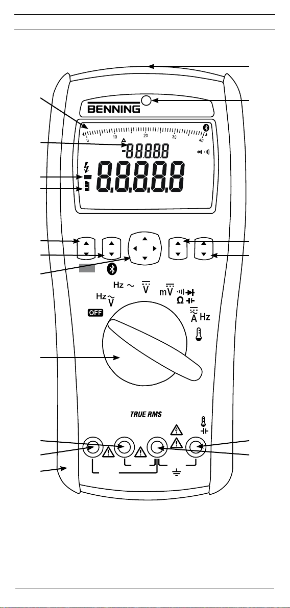
Bild 1: Gerätefrontseite
Fig. 1: Front tester panel
2
07/ 2016
MAX
10 A
FUSED
MAX
400 mA
FUSED
BENNING MM 12
Page 3
D
MM 12
AUTOTEST T-POINT
▲
dBm % HFR
MAX-MIN AVG
µms VAFs
▼
AutoPeak HOLD
MkHz
AC+DC
s°F°C%
µmVAF
MkΩHz
MAX MIN AVG % dB dBm SETUP
A-SAVE SAVE LOAD CLR RATE LOG MEM
RANGE HFR ENTER A HOLD
CANCEL P HOLD
AC+DC
°C/°F
AC+DC
mV
AutoV
LoZ
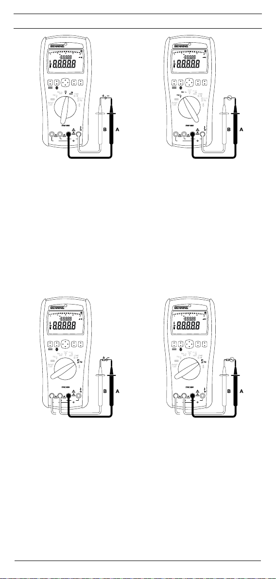
Bild 2: Gleichspannungsmessung
Fig. 2: Direct voltage measurement
MAX-MIN AVG
AutoPeak HOLD
MAX MIN AVG % dB dBm SETUP
A-SAVE SAVE LOAD CLR RATE LOG MEM
RANGE HFR ENTER A HOLD
°C/°F
AutoV
LoZ
AC+DC
Hz
mA COM
A
V Ω
600V
CAT IV
MAX
1000V
MAX
400 mA
CAT III
10 A
FUSED
FUSED
MM 12
AUTOTEST T-POINT
▲
dBm % HFR
µms VAFs
▼
MkHz
AC+DC
s°F°C%
µmVAF
MkΩHz
CANCEL P HOLD
AC+DC
AC+DC
mV
AC+DC
MM 12
AUTOTEST T-POINT
▲
dBm % HFR
MAX-MIN AVG
µms VAFs
▼
AutoPeak HOLD
MkHz
AC+DC
s°F°C%
µmVAF
MkΩHz
MAX MIN AVG % dB dBm SETUP
A-SAVE SAVE LOAD CLR RATE LOG MEM
RANGE HFR ENTER A HOLD
CANCEL P HOLD
AC+DC
°C/°F
AC+DC
mV
AutoV
LoZ
Bild 3: Wechselspannungsmessung
Fig. 3: Alternating voltage measurement
MAX-MIN AVG
AutoPeak HOLD
MAX MIN AVG % dB dBm SETUP
A-SAVE SAVE LOAD CLR RATE LOG MEM
RANGE HFR ENTER A HOLD
°C/°F
AutoV
LoZ
AC+DC
Hz
mA COM
A
V Ω
600V
CAT IV
MAX
1000V
MAX
400 mA
CAT III
10 A
FUSED
FUSED
MM 12
AUTOTEST T-POINT
▲
dBm % HFR
µms VAFs
▼
MkHz
AC+DC
s°F°C%
µmVAF
MkΩHz
CANCEL P HOLD
AC+DC
AC+DC
mV
AC+DC
Hz
mA COM
A
V Ω
600V
CAT IV
MAX
1000V
MAX
400 mA
CAT III
10 A
FUSED
FUSED
Bild 4: Gleichstrommessung
Fig. 4: DC current measurement
3
07/ 2016
BENNING MM 12
Bild 5: Wechselstrommessung
Fig. 5: AC current measurement
Hz
mA COM
A
V Ω
600V
CAT IV
MAX
1000V
MAX
400 mA
CAT III
10 A
FUSED
FUSED
Page 4

D
MM 12
AUTOTEST T-POINT
▲
dBm % HFR
MAX-MIN AVG
µms VAFs
▼
AutoPeak HOLD
MkHz
AC+DC
s°F°C%
µmVAF
MkΩHz
MAX MIN AVG % dB dBm SETUP
A-SAVE SAVE LOAD CLR RATE LOG MEM
RANGE HFR ENTER A HOLD
CANCEL P HOLD
AC+DC
°C/°F
AC+DC
mV
AutoV
LoZ
Bild 6: Widerstandsmessung
Fig. 6: Resistance measurement
MAX-MIN AVG
AutoPeak HOLD
MAX MIN AVG % dB dBm SETUP
A-SAVE SAVE LOAD CLR RATE LOG MEM
RANGE HFR ENTER A HOLD
°C/°F
AutoV
LoZ
AC+DC
Hz
mA COM
A
V Ω
600V
CAT IV
MAX
1000V
MAX
400 mA
CAT III
10 A
FUSED
FUSED
MM 12
AUTOTEST T-POINT
▲
dBm % HFR
µms VAFs
▼
MkHz
AC+DC
s°F°C%
µmVAF
MkΩHz
CANCEL P HOLD
AC+DC
AC+DC
mV
AC+DC
MM 12
AUTOTEST T-POINT
▲
dBm % HFR
MAX-MIN AVG
µms VAFs
▼
AutoPeak HOLD
MkHz
MAX MIN AVG % dB dBm SETUP
A-SAVE SAVE LOAD CLR RATE LOG MEM
RANGE HFR ENTER A HOLD
CANCEL P HOLD
AC+DC
°C/°F
AC+DC
mV
AutoV
LoZ
mA COM
A
600V
CAT IV
MAX
1000V
MAX
400 mA
CAT III
10 A
FUSED
FUSED
Bild 7: Diodenprüfung
Fig. 7: Diode Testing
MM 12
AUTOTEST T-POINT
▲
dBm % HFR
MAX-MIN AVG
µms VAFs
▼
AutoPeak HOLD
MkHz
MAX MIN AVG % dB dBm SETUP
A-SAVE SAVE LOAD CLR RATE LOG MEM
RANGE HFR ENTER A HOLD
CANCEL P HOLD
AC+DC
°C/°F
AC+DC
mV
AutoV
LoZ
AC+DC
s°F°C%
µmVAF
MkΩHz
AC+DC
Hz
V Ω
AC+DC
s°F°C%
µmVAF
MkΩHz
AC+DC
Hz
mA COM
A
V Ω
600V
CAT IV
MAX
1000V
MAX
400 mA
CAT III
10 A
FUSED
FUSED
Bild 8: Durchgangsprüfung mit Summer
Fig. 8: Continuity Testing with buzzer
4
07/ 2016
BENNING MM 12
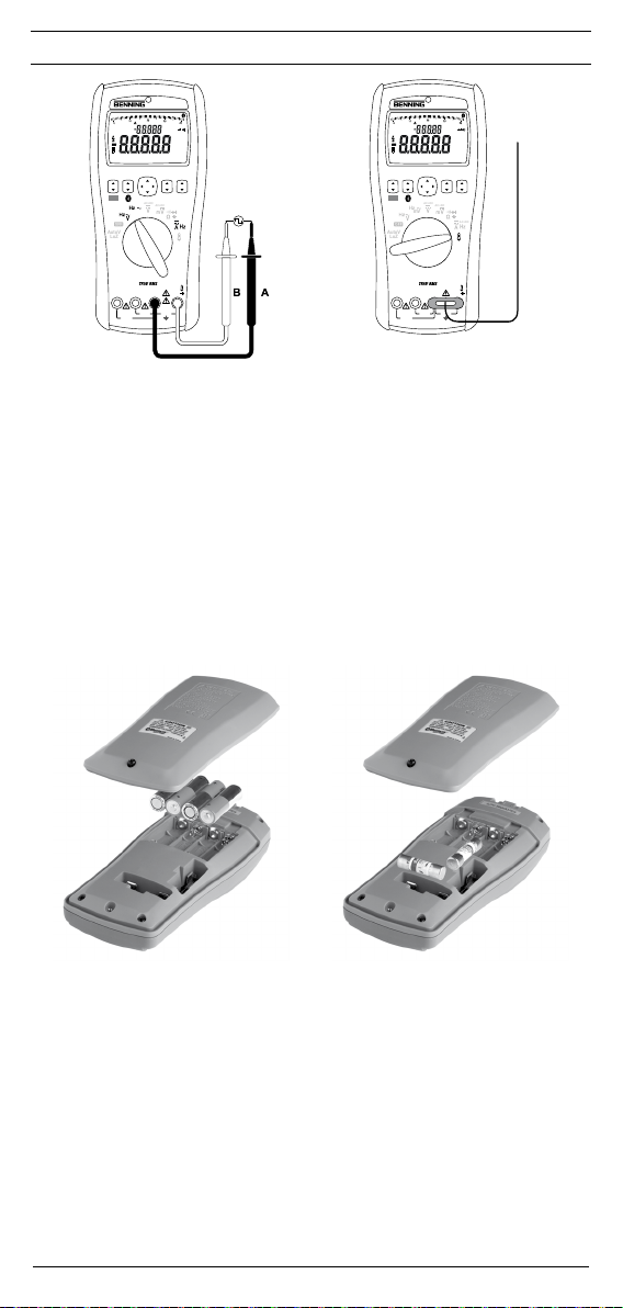
Bild 9: Kapazitätsmessung
Fig. 9: Capacity Testing
Hz
mA COM
A
V Ω
600V
CAT IV
MAX
1000V
MAX
400 mA
CAT III
10 A
FUSED
FUSED
Page 5
D
MM 12
AUTOTEST T-POINT
▲
dBm % HFR
MAX-MIN AVG
µms VAFs
▼
AutoPeak HOLD
MkHz
AC+DC
s°F°C%
µmVAF
MkΩHz
MAX MIN AVG % dB dBm SETUP
A-SAVE SAVE LOAD CLR RATE LOG MEM
RANGE HFR ENTER A HOLD
CANCEL P HOLD
AC+DC
°C/°F
AC+DC
mV
AutoV
LoZ
Bild 10: Frequenzmessung
Fig. 10: Frequency measurement
AC+DC
Hz
mA COM
A
V Ω
600V
CAT IV
MAX
1000V
MAX
400 mA
CAT III
10 A
FUSED
FUSED
MM 12
AUTOTEST T-POINT
▲
dBm % HFR
MAX-MIN AVG
µms VAFs
▼
AutoPeak HOLD
MkHz
AC+DC
s°F°C%
µmVAF
MkΩHz
MAX MIN AVG % dB dBm SETUP
A-SAVE SAVE LOAD CLR RATE LOG MEM
RANGE HFR ENTER A HOLD
CANCEL P HOLD
AC+DC
°C/°F
AC+DC
mV
AutoV
LoZ
Bild 11: Temperaturmessung
Fig. 11: Temperature measurement
AC+DC
Hz
mA COM
A
V Ω
600V
CAT IV
MAX
1000V
MAX
400 mA
CAT III
10 A
FUSED
FUSED
Bild 12: Batteriewechsel
Fig. 12: Battery replacement
5
07/ 2016
BENNING MM 12
Bild 13: Sicherungswechsel
Fig. 13: Fuse replacement
Page 6
D
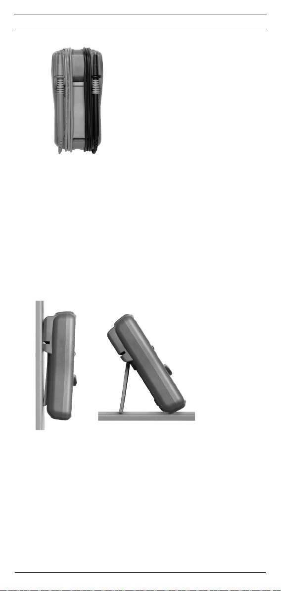
Bild 14: Aufwicklung der Sicherheitsmessleitung
Fig. 14: Winding up the safety measuring leads
Bild 15: Aufstellung des BENNING MM 12
Fig. 15: Standing up the BENNING MM 12
6
07/ 2016
BENNING MM 12
Page 7
D
Bedienungsanleitung
BENNING MM 12
TRUE RMS Digital-Multimeter zur
- Gleich-/ Wechselspannungsmessung
- Gleich-/ Wechselstrommessung
- Widerstandsmessung
- Dioden-/ Durchgangsprüfung
- Kapazitätsmessung
- Frequenzmessung
- Temperaturmessung
Inhaltsverzeichnis
1. Benutzerhinweise
2. Sicherheitshinweise
3. Lieferumfang
4. Gerätebeschreibung
5. Funktionen des Multimeters
5.1 Allgemeine Angaben
5.2 Tastenfunktionen
5.3 Menüfunktionen
5.4 Datenlogger-Funktion LOG
5.5 Speicher-Funktion MEM
5.6 Datenübertragung zum PC und Smartphone/Tablet
6. Umgebungsbedingungen
7. Elektrische Angaben
8. Messen mit dem BENNING MM 12
9. Instandhaltung
10. Anwendung des Gummi-Schutzrahmens
11. Technische Daten des Messzubehörs
12. Umweltschutz
1. Benutzerhinweise
Diese Bedienungsanleitung richtet sich an
- Elektrofachkräfte und
- elektrotechnisch unterwiesene Personen
Das BENNING MM 12 ist zur Messung in trockener Umgebung vorgesehen. Es darf nicht in
Stromkreisen mit einer höheren Nennspannung als 1000 V AC/ DC eingesetzt werden (Näheres
hierzu im Abschnitt 6. „Umgebungsbedingungen“). In der Bedienungsanleitung und auf dem
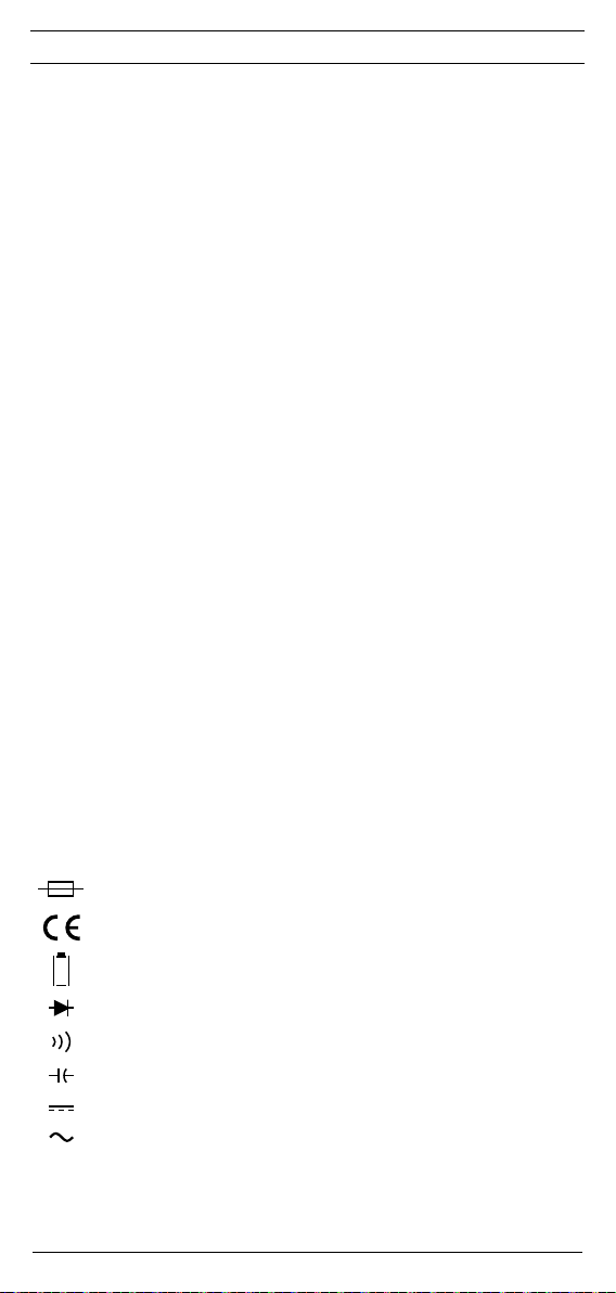
BENNING MM 12 werden folgende Symbole verwendet:
Warnung vor elektrischer Gefahr!
Steht vor Hinweisen, die beachtet werden müssen, um Gefahren für Menschen zu
vermeiden.
Achtung Dokumentation beachten!
Das Symbol gibt an, dass die Hinweise in der Bedienungsanleitung zu beachten
sind, um Gefahren zu vermeiden.
Dieses Symbol auf dem BENNING MM 12 bedeutet, dass das BENNING MM 12
schutzisoliert (Schutzklasse II) ausgeführt ist.
Dieses Symbol auf dem BENNING MM 12 weist auf die eingebauten Sicherungen
hin.
Dieses Symbol auf dem BENNING MM 12 bedeutet, dass das BENNING MM 12
konform zu den EU-Richtlinien ist.
Dieses Symbol erscheint in der Anzeige für eine entladene Batterie.
Dieses Symbol kennzeichnet den Bereich „Diodenprüfung“.
Dieses Symbol kennzeichnet den Bereich “Durchgangsprüfung”. Der Summer dient
der akustischen Er geb nis aus gabe.
Dieses Symbol kennzeichnet den Bereich “Kapazitätsprüfung”.
(DC) Gleich- Spannung oder Strom.
(AC) Wechsel- Spannung oder Strom.
Erde (Spannung gegen Erde).
7
07/ 2016
BENNING MM 12
Page 8

D
2. Sicherheitshinweise
Das Gerät ist gemäß
DIN VDE 0411 Teil 1/ EN 61010-1
DIN VDE 0411 Teil 2-033/ EN 61010-2-033
DIN VDE 0411 Teil 031/ EN 61010-031
gebaut und geprüft und hat das Werk in einem sicherheitstechnisch einwandfreien Zustand
verlassen.
Um diesen Zustand zu erhalten und einen gefahrlosen Betrieb sicherzustellen, muss der
Anwender die Hinweise und Warnvermerke beachten, die in dieser Anleitung enthalten sind.
Fehlverhalten und Nichtbeachtung der Warnungen können zu schwerwiegenden Verletzungen
oder zum Tode führen.
Extreme Vorsicht bei Arbeiten um blanke Leiter oder Hauptleitungsträger. Ein
Kontakt mit Leitern kann einen Elektroschock verursachen.
Das Gerät darf nur in Stromkreisen der Überspannungskategorie III mit max.
1000 V Leiter gegen Erde oder Überspannungskategorie IV mit 600 V Leiter
gegen Erde benutzt werden.
Hierzu sind geeignete Messleitungen zu verwenden. Bei Messungen innerhalb der Messkategorie III darf das hervorstehende leitfähige Teil einer
Kontaktspitze der Messleitung nicht länger als 4 mm sein.
Vor Messungen innerhalb der Messkategorie III müssen, die dem Set
beigestellten, mit CAT III und CAT IV gekennzeichneten, Aufsteckkappen
auf die Kontaktspitzen aufgesteckt werden. Diese Maßnahme dient dem
Benutzerschutz.
Beachten Sie, dass Arbeiten an spannungsführenden Teilen und Anlagen
grundsätzlich gefährlich sind. Bereits Spannungen ab 30 V AC und 60 V DC
können für den Menschen lebensgefährlich sein.
Um eine Gefährdung auszuschließen, messen Sie eine vorhandene Spannung
zuerst immer ohne Tiefpassfilter (ohne Hochfrequenzunterdrückung), um
eine gefährliche Spannung zu erkennen.
Vor jeder Inbetriebnahme überprüfen Sie das Gerät und die Leitungen auf
Beschädigungen.
Ist anzunehmen, dass ein gefahrloser Betrieb nicht mehr möglich ist, ist das Gerät außer Betrieb
zu setzen und gegen unbeabsichtigten Betrieb zu sichern.
Es ist anzunehmen, dass ein gefahrloser Betrieb nicht mehr möglich ist,
- wenn das Gerät oder die Messleitungen sichtbare Beschädigungen aufweisen,
- wenn das Gerät nicht mehr arbeitet,
- nach längerer Lagerung unter ungünstigen Verhältnissen,
- nach schweren Transportbeanspruchungen,
- wenn das Gerät oder die Messleitungen feucht sind.
Um eine Gefährdung auszuschließen
- berühren Sie die Messleitungen nicht an den blanken Messspitzen,
- stecken Sie die Messleitungen in die entsprechend gekennzeichneten
Messbuchsen am Multimeter
Reinigung:
Das Gehäuse regelmäßig mit einem Tuch und Reinigungsmittel trocken abwi-
schen. Kein Poliermittel oder Lösungsmittel verwenden.
3. Lieferumfang
Zum Lieferumfang des BENNING MM 12 gehören:
3.1 ein Stück BENNING MM 12,
3.2 ein Stück Software BENNING PC-Win MM 12
3.3 ein Stück serielles Datenkabel mit USB 2.0 kompatiblen Anschluss
3.4 ein Stück Sicherheitsmessleitung, rot (L = 1,4 m),
3.5 ein Stück Sicherheitsmessleitung, schwarz (L = 1,4 m),
3.6 ein Stück Drahttemperaturfühler Typ K,
3.7 ein Stück Gummi-Schutzrahmen,
3.8 ein Stück Magnetaufhänger mit Adapter und Riemen
3.9 ein Stück Kompakt-Schutztasche,
3.10 vier Stück 1,5 V Mignon-Batterien (AA/ IEC LR6) und zwei unterschiedliche Sicherungen (zur Erstbestückung im Gerät eingebaut),
3.11 eine Bedienungsanleitung.
8
07/ 2016
BENNING MM 12
Page 9

D
Hinweis auf optionales Zubehör:
- Temperaturfühler (K-Typ) aus V4A-Rohr (T.Nr. 044121)
Anwendung: Einstichfühler für weichplastische Medien, Flüssigkeiten, Gas und Luft
Messbereich: - 196 °C bis + 800 °C
Abmessungen: Länge = 210 mm, Rohrlänge = 120 mm, Rohrdurchmesser = 3 mm, V4A
Hinweis auf Verschleißteile:
- Das BENNING MM 12 enthält Sicherungen zum Überlastschutz:
Ein Stück Sicherung Nennstrom 11 A flink (1000 V) 20 kA, D = 10,3 mm, L = 38,1 mm (T.Nr.
10016656) und ein Stück Sicherung Nennstrom 440 mA flink (1000 V) 10 kA, D = 10 mm,
L = 34,9 mm (T.Nr. 10016655).
- Das BENNING MM 12 wird durch vier eingebaute 1,5 V Mignon-Batterien (AA/ IEC LR6)
gespeist.
- Die oben genannten Sicherheitsmessleitungen (geprüftes Zubehör) entsprechen CAT III
1000 V/ CAT IV 600 V und sind für einen Strom von 10 A zugelassen.
4. Gerätebeschreibung
siehe Bild 1: Gerätefrontseite
Die in Bild 1 angegebenen Anzeige- und Bedienelemente werden wie folgt bezeichnet:
1
Digitalanzeige, für den Messwert, die Bargraphanzeige und die Anzeige der Bereichs über-
schreitung,
2
Unterdisplay,
3
Polaritätsanzeige,
4
Batteriezustandsanzeige,
5
Taste RANGE bzw. Funktion
RANGE (oben/▲), Umschaltung automatischer/ manueller Messbereich,
Funktion (unten/▼), wählt die Zweit-, Dritt- oder Viertfunktion.
6
Taste HFR bzw. Bluetooth
HFR (oben/▲) Hochfrequenzunterdrückung (Tiefpassfilter)
Bluetooth® (unten/▼) Aktivierung der Bluetooth-Schnittstelle
7
Taste Cursor, Menüsteuerung nach oben/▲, unten/▼, rechts/►, links/◄
8
Taste ENTER bzw. CANCEL
ENTER (oben/▲) bestätigt die Funktion
CANCEL (unten/▼) beendet die Funktion
9
Taste A HOLD bzw. P HOLD
A HOLD (oben/▲), Auto-HOLD, automatische Messwertspeicherung
P HOLD (unten/▼), Peak-HOLD, Spitzenwertspeicherung
J
Drehschalter, für Wahl der Messfunktion,
K
Buchse (positive1), für V, Ω, , Hz,
L
COM-Buchse, gemeinsame Buchse für Strom-, Spannungs-, Widerstands-, Frequenz-,
Temperatur-, Kapazitätsmessungen, Durchgangs- und Diodenprüfung,
M
Buchse (positive1), für mA-Bereich, für Ströme bis 400 mA,
N
Buchse (positive1), für 10 A-Bereich, für Ströme bis 10 A,
O
Gummi-Schutzrahmen
P
optische Schnittstelle, zur Aufnahme des am Datenkabels befindlichen Adapters,
Q
Lichtsensor für Beleuchtung des LC-Displays
1) Hierauf bezieht sich die automatische Polaritätsanzeige für Gleichstrom und -spannung
5. Funktionen des Multimeters
5.1 Allgemeine Angaben
5.1.1
Die Digitalanzeige 1 ist als 3¾ oder 4¾-stellige Flüssigkristallanzeige mit 15 mm
Schrifthöhe mit Dezimalpunkt ausgeführt. Der größte Anzeigewert ist 4.000/ 40.000 Digit.
5.1.2 Die Bargraphanzeige besteht aus 40 Segmenten.
5.1.3 Die Polaritätsanzeige 3 wirkt automatisch. Es wird nur eine Polung entgegen der
Buchsendefinition mit „-“ angezeigt.
5.1.4 Die Bereichsüberschreitung wird mit „0L“ oder „- 0L“ und teilweise einer akustischen
Warnung angezeigt.
Achtung, keine Anzeige und Warnung bei Überlast! Ein Überschreiten von gefährli-
chen Berührungsspannungen (> 60 V DC/ 30 V AC rms) wird durch ein zusätzlich
blinkendes Symbol „“ angezeigt.
5.1.5 Das BENNING MM 12 bestätigt jede Tastenbetätigung mit einem Signalton. Ungültige
Tastenbetätigungen werden mit einem zweifachen Signalton bestätigt. Bei unkorrekter
Beschaltung der Buchsen für den mA- M/ A-Bereich N warnt das BENNING MM 12
mit einem Signalton und der Anzeige von ProbE im Display 1.
Der Warnton und die Anzeige ProbE im Display 1 erlöschen, wenn eine
Sicherheitsmessleitung in die Buchse für den mA- M/ A-Bereich N gesteckt wird und
der entsprechende Strommessbereich über den Drehschalter J angewählt wurde.
Im Falle einer defekten Sicherung warnt das BENNING MM 12 mit einem Signalton
und der Anzeige FUSE im Display 1.
5.1.6 Die Messrate des BENNING MM 12 beträgt nominal 10 Messungen pro Sekunde (s)
für die Digitalanzeige.
5.1.7 Das BENNING MM 12 wird durch den Drehschalter J ein- oder ausgeschaltet.
Ausschaltstellung „OFF“.
5.1.8 Das BENNING MM 12 schaltet sich nach ca. 10 Minuten selbsttätig ab (APO, Auto-
Power-Off). Es schaltet sich wieder ein, wenn eine Taste oder der Drehschalter
betätigt wird. Die Abschaltung ist in dem Setup-Menü individuell einstellbar (siehe
Abschnitt 5.3.5).
9
07/ 2016
®
BENNING MM 12
Page 10
D
5.1.9 Temperaturkoeffizient des Messwertes: 0,1 x (angegebene Mess genauigkeit)/ °C
< 18 °C oder > 28 °C, bezogen auf den Wert bei der Referenz temperatur von 23 °C.
5.1.10 Das BENNING MM 12 wird durch vier 1,5 V Mignon-Batterien (AA/ IEC LR6) gespeist.
5.1.11 Die Batterieanzeige 4 zeigt permanent die verbleibende Batteriekapazität über maxi-
mal 3 Segmente an.
Sobald alle Segmente in dem Batteriesymbol erloschen sind und das
Batteriesymbol blinkt, tauschen Sie umgehend die Batterien gegen neue
Batterien aus, um eine Gefährdung durch Fehlmessungen für den Menschen
zu vermeiden.
5.1.12 Die Lebensdauer einer Batterie beträgt etwa 50 Stunden (Alkalibatterie).
5.1.13 Geräteabmessungen:
(L x B x H) = 200 x 87 x 40 mm ohne Gummi-Schutzrahmen
(L x B x H) = 206 x 94 x 54 mm mit Gummi-Schutzrahmen
Gerätegewicht:
480 g ohne Gummi-Schutzrahmen
640 g mit Gummi-Schutzrahmen
5.1.14 Die mitgelieferten Sicherheitsmessleitungen sind ausdrücklich für die Nennspannung
und dem Nennstrom des BENNING MM 12 geeignet.
5.1.15 Das BENNING MM 12 wird durch einen Gummi-Schutzrahmen O vor mechani-
scher Beschädigung geschützt. Der Gummi-Schutzrahmen O ermöglicht es, das
BENNING MM 12 während der Messungen aufzustellen oder aufzuhängen.
5.1.16 Das BENNING MM 12 besitzt kopfseitig eine optische Schnittstelle P. Diese dient
der galvanischen Trennung des Messsignals zu einem PC/ Laptop. Das beigefügte
Datenkabel dient der Messdatenübertragung und ist mit einem USB 2.0 kompatiblen
Anschluss ausgerüstet.
5.1.17 Das BENNING MM 12 unterstützt die drahtlose Datenübertragung per Bluetooth® 4.0
Standard zu einem Android- oder IOS-Gerät (Smartphone/ Tablet).
5.2 Tastenfunktionen
Die Bedientasten 5, 6, 8 und 9 besitzen eine Doppelfunktion und können nach oben/▲ und
unten/▼ betätigt werden.
5.2.1 Die Taste RANGE 5 (oben/▲) dient zur Weiterschaltung der manuellen Messbereiche
bei gleichzeitiger Ausblendung von „AUTO“ im Display. Durch längeren Tastendruck (2
s) wird die automatische Bereichswahl gewählt (Anzeige „AUTO“).
5.2.2 Die Taste Funktion 5 (unten/▼) wählt die Zweit-, Dritt- oder Viertfunktionen der
Drehschalterstellung:
Drehschalterstellung: Zweitfunktion: Dritt-/ Viertfunktion:
V AC Hz
mV AC Hz
V DC V AC + DC
mV DC mV AC + DC
Ω
A AC A DC A AC + DC/ Hz
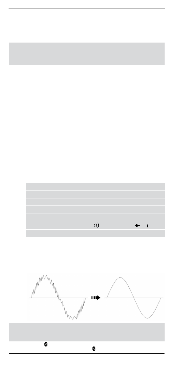
5.2.3 Die Taste HFR 6 (oben/▲) dient der Zuschaltung eines Tiefpassfilters (Hoch fre-
quenz unterdrückung) in der Funktion V AC und A AC, um hochfrequente Impulse,
z.B. an getakteten Motorantrieben auszufiltern. Symbol „HRF“ im LC-Display 1.
Die Grenzfrequenz (- 3 dB) des Filters liegt bei fg = 800 Hz. Beim Erreichen der
Grenzfrequenz fg ist der Anzeigewert um den Faktor 0,707 kleiner als der tatsächliche
Wert ohne Filter.
ohne HRF (ohne Tiefpassfilter) mit HRF (mit Tiefpassfilter)
/
Um eine Gefährdung auszuschließen, messen Sie eine vorhandene Spannung
zuerst immer ohne Tiefpassfilter (Hochfrequenzunter drückung), um eine
gefährliche Spannung zu erkennen.
5.2.4 Die Taste Bluetooth® 6 (unten/▼) aktiviert die Bluetooth®-Schnittstelle bei
gleichzeitiger Einblendung des Symbols im LC-Display 1.
10
07/ 2016
BENNING MM 12
Page 11

D
5.2.5 Die Taste Cursor 7 (oben/▲, unten/▼, rechts/►, links/◄) dient der Auswahl der
Menüfunktion im LC-Display 1.
5.2.6 Die Taste ENTER 8 (oben/▲) bestätigt eine ausgewählte Funktion.
5.2.7 Die Taste CANCEL 8 (unten/▼) beendet eine ausgewählte Funktion.
5.2.8 Die Taste A-HOLD 9 (oben/▲) (automatische Messwertspeicherung) speichert den
Anzeigewerte im Unterdisplay 2. Im Display 1 wird gleichzeitig das Symbol „Auto
HOLD“ eingeblendet. Sobald ein neuer stabiler Messwert mit einer Änderung > 5 Digit
(Auflösung 3¾-stellig) erfasst wird, wird das Unterdisplay 2 automatisch mit dem
neuen Wert aktualisiert. Erneutes Betätigen der Taste schaltet in den Messmodus
zurück.
Die automatische Messwertspeicherung lässt sich in dem Setup-Menü deaktivieren.
5.2.9 Die Taste P-HOLD 9 (unten/▼) (Spitzenwertspeicherung) erfasst und speichert den
„Peak Max“-/ „Peak MIN“-Wert (Funktion: V, mV und A) bei gleichzeitiger Einblendung
von „PeakHOLD“ im Display 1. Jede erneute Speicherung des „Peak Max“-/ „Peak
MIN“-Wertes wird durch einen Signalton bestätigt. Der „Peak Max“-/ „Peak MIN“-Wert
wird über die Taste P-HOLD 9 (unten/▼) abgerufen und in dem Unterdisplay 2
angezeigt. Ein längerer Tastendruck (2 s) auf die Taste P-HOLD 9 (unten/▼) schaltet
in den Normalmodus zurück. Die Ansprechzeit der P-HOLD-Funktion liegt bei 10 µs.
5.3 Menüfunktionen
Über die Taste Cursor 7 lassen sich die im LC-Display 1 eingeblendeten Funktionen anwählen.
Eine angewählte Funktion wird durch ein blinkendes Symbol dargestellt. Um eine Funktion zu
starten, betätigen Sie die Taste ENTER 8 (oben/▲) und das Symbol wird mit einem Unterstrich
dargestellt. Um eine Funktion zu beenden, betätigen Sie die Taste CANCEL 8 (unten/▼).
5.3.1 MAX, MIN, AVG (Mittelwert)-Funktion
Wählen Sie über die Taste Cursor 7 die Funktion „MAX“, „MIN“ oder „AVG “ und star-
ten Sie durch Betätigung der Taste ENTER 8 (oben/▲) die Messung. Die Funktion
erfasst und speichert automatisch den höchsten Messwert (MAX), den niedrigsten
Messwert (MIN) und den Mittelwert (AVG) einer Messreihe und zeigt den jeweiligen
Wert im Unterdisplay 2 an. Durch Betätigung der Taste CANCEL 8 (unten/▼) wird
in den Normalmodus zurückgeschaltet.
5.3.2 Relativwert-Funktion ∆
Wählen Sie über die Taste Cursor 7 die Relativwert-Funktion „∆“ und starten Sie
durch Betätigung der Taste ENTER 8 (oben/▲) die Messung. Die RelativwertFunktion „∆“ speichert den aktuellen Anzeigewert auf dem Unterdisplay 2 und zeigt
die Differenz (Offset) zwischen dem gespeicherten Messwert und den folgenden
Messwerten auf dem Display 1 an.
Beispiel:
Gespeicherter Referenzwert: 235 V (Unterdisplay 2), aktueller Messwert: 230 V,
ergibt eine Differenz (Offset) von 5 V (Hauptdisplay 1). Durch Betätigung der Taste
CANCEL 8 (unten/▼) wird in den Normalmodus zurückgeschaltet.
5.3.3 Relativwert-Funktion %
Wählen Sie über die Taste Cursor 7 die Relativwert-Funktion „%“ und starten Sie
durch Betätigung der Taste ENTER 8 (oben/▲) die Messung. Die Relativwert-
Funktion „%“ speichert den aktuellen Anzeigewert auf dem Unterdisplay 2 und zeigt
den relativen Prozentwert zwischen dem gespeicherten Messwert und den folgenden
Messwerten auf dem Display 1 an.
Relativwert % = [(Messwert - Referenzwert) / Referenzwert] x 100 %
Beispiel:
Gespeicherter Referenzwert: 235 V (Unterdisplay 2), aktueller Messwert: 230 V,
ergibt einen relativen Prozentwert von - 2,13 % V (Hauptdisplay 1). Durch Betätigung
der Taste CANCEL 8 (unten/▼) wird in den Normalmodus zurück ge schaltet.
5.3.4 Pegelmessung in dB/ dBm
Die Pegelmessung in Dezibel ist das logarithmische Verhältnis zweier Leistungen P1
zu P2. LP = 10 x log (P1/ P2).
Befindet sich das BENNING MM 12 in der Funktion der Wechselspannungsmessung
(V AC), wählen Sie über die Taste Cursor 7 die Menüfunktion „dB“ oder „dBm“
an und starten Sie durch Betätigung der Taste ENTER 8 (oben/▲) die Messung.
Im Unterdisplay 2 wird der Spannungspegel in dB mit einem Bezugswert von 1 V
angezeigt bzw. der Leistungspegel in dBm angezeigt (Bezugswert: 1 mW an 600 Ω).
Spannungs- und Leistungspegel errechnen sich wie folgt:
11
07/ 2016
BENNING MM 12
Page 12
D
Spannungspegel in dB: Bezugswert: 1 V
Leistungspegel in dBm: Bezugswert: 1 mW an 600 Ω
Durch Betätigung der Taste CANCEL 8 (unten/▼) wird in den Normalmodus zurück-
geschaltet.
5.3.5 SETUP-Menü
Das BENNING MM 12 verfügt über individuelle Einstellmöglichkeiten. Um eine
Einstellung zu ändern, wählen Sie über die Taste Cursor 7 das Menü „SETUP“ an.
Betätigen Sie die Taste ENTER 8 (oben/▲), um das Menü „SETUP“ zu öffnen. Über
die Taste Cursor 7 können folgende Einstellungen vorgenommen werden:
APO Automatische Abschaltung: 1 Minute bis 30 Minuten oder OFF (AUS)
bL it LC-Displaybeleuchtung: Auto (automatisch), On (AN) oder OFF (AUS)
bEEP Signalton: On (AN) oder OFF (AUS)
A.Hold Automatische Messwertspeicherung: On (AN) oder OFF (AUS)
Cnt in Grenzwert der Durchgangsprüfung: 10 Ω bis 50 Ω
diGit Stellenanzahl des LC-Display: Lo (niedrig) oder Hi (hoch)
TEMP Einheit der Temperatur °C oder °F
RESET Werkseinstellung:
Durch Betätigung der Taste CANCEL 8 (unten/▼) wird in den Normalmodus zurück-
geschaltet.
5.4 Datenlogger-Funktion „LOG“
Die Datenlogger-Funktion „LOG“ ermöglicht das automatische Speichern von Messreihen
mit einem vordefinierten Messintervall und bis zu 40.000 Messwerten. Das Messintervall kann
von 1 s bis 600 s eingestellt werden. Die Messwerte können zu einem späteren Zeitpunkt über
das Display 1, der optischen Schnittstelle P oder per Bluetooth® zur Weiterverarbeitung
ausgelesen werden.
Wählen Sie über die Taste Cursor 7 die Funktion „LOG“ und betätigen Sie die Taste ENTER 8
(oben/▲), um das Menü „LOG“ zu öffnen.
Über die Taste Cursor 7 können Sie folgende Untermenüs anwählen:
SAVE
LOAD
CLR
RATE
MAX
MIN
Die gespeicherten Messwerte des Datenloggers lassen sich über die mitgelieferte PC-Software
BENNING PC-Win MM 12 auslesen und als MS Excel®-Datei speichern.
5.5 Speicher-Funktion „MEM“
Die Speicher-Funktion „MEM“ ermöglicht das automatische und manuelle Speichern von
Mess reihen mit bis zu 1.000 Messwerten. Die Messwerte können zu einem späteren Zeitpunkt
über das Display 1, der optischen Schnittstelle P oder per Bluetooth® zur Weiterverarbeitung
ausgelesen werden.
Wählen Sie über die Taste Cursor 7 die Funktion „MEM“ und betätigen Sie die Taste ENTER
8
(oben/▲), um das Menü „MEM“ zu öffnen.
Über die Taste Cursor 7 können Sie folgende Untermenüs anwählen:
12
07/ 2016
Die Taste ENTER 8 (oben/▲) startet die Datenlogger-Funktion „LOG“. Bei
erneuter Betätigung der Taste ENTER 8 (oben/▲) pausiert die Messung, nach
nochmaliger Betätigung wird die Messung weiter fortgesetzt. Der Abbruch erfolgt
durch Taste CANCEL 8 (unten/▼).
Hinweis:
Jeder erneute Start löscht alle gespeicherten Messwerte im Datenlogger (LOG).
Die Taste ENTER 8 (oben/▲) öffnet die gespeicherten Messwerte aus dem
Datenlogger. Über die Taste Cursor 7 (oben/▲, unten/▼) lassen sich die
gespeicherten Messwerte mit Angabe der Speicherplatznummer im Display 1
aufrufen. Der Abbruch erfolgt durch Taste CANCEL 8 (unten/▼).
Die Taste ENTER 8 (oben/▲) löscht alle gespeicherten Messwerte im
Datenlogger (LOG).
Die Taste ENTER 8 (oben/▲) erlaubt die Einstellung der Abtastrate, die den
Zeitraum zwischen zwei Messpunkte definiert. Über die Taste Cursor 7 ist die
Abtastrate von 1 s bis 600 s einstellbar.
Die Abweichung des Zeitgebers (Timers) beträgt pro Stunde weniger als 3 s.
Die Taste ENTER 8 (oben/▲) öffnet den Maximalwert einer gespeicherten
Messreihe im Datenlogger.
Die Taste ENTER 8 (oben/▲) öffnet den Minimalwert einer gespeicherten
Messreihe im Datenlogger.
BENNING MM 12
LU = 20 x log
LP = 10 x log
U
[dB]
1 V
P
[dBm] LP = 10 x log
1 mW
YES (JA), bestätigen mit Taste ENTER 8
(oben/▲)
600 Ω
1 mW
2
U
[dBm]
Page 13

D
A-SAVE
SAVE
LOAD
CLR
MAX
MIN
5.6 Datenübertragung zum PC und Smartphone/ Tablet
5.6.1 Datenübertragung zum PC
Für die Messwertübertragung installieren Sie bitte die PC-Software BENNING PC-Win
Die PC-Software BENNING PC-Win MM 12 besitzt folgende Funktionen:
5.6.2 Datenübertragung zum Smartphone/ Tablet
Das BENNING MM 12 verfügt über eine Bluetooth® Low Energy 4.0 Schnittstelle, um
Die hierzu nötige APP „BENNING MM-CM Link“ finden Sie im Google Playstore und
6. Umgebungsbedingungen
- Das BENNING MM 12 ist für Messungen in trockener Umgebung vorgesehen,
- Barometrische Höhe bei Messungen: Maximal 2222 m,
- Überspannungskategorie/ Aufstellungskategorie: IEC 60664-1/ IEC 61010-1 → 600 V
- Verschmutzungsgrad: 2,
- Schutzart: IP 30 (DIN VDE 0470-1 IEC/ EN 60529)
3 - erste Kennziffer: Schutz gegen Zugang zu gefährlichen Teilen und Schutz gegen feste
0 - zweite Kennziffer: Kein Wasserschutz,
- Arbeitstemperatur und relative Luftfeuchte:
Bei Arbeitstemperatur von 0 °C bis 30 °C: relative Luftfeuchte kleiner 80 %,
Bei Arbeitstemperatur von 31 °C bis 40 °C: relative Luftfeuchte kleiner 75 %,
Bei Arbeitstemperatur von 41 °C bis 50 °C: relative Luftfeuchte kleiner 45 %,
- Lagerungstemperatur: Das BENNING MM 12 kann bei Temperaturen von - 20 °C bis
7. Elektrische Angaben
Bemerkung: Die Messgenauigkeit wird angegeben als Summe aus
- einem relativen Anteil des Messwertes und
- einer Anzahl von Digit (d.h. Zahlenschritte der letzten Stelle).
Diese Messgenauigkeit gilt bei Temperaturen von 18 °C bis 28 °C und einer relativen Luftfeuchtig keit kleiner 80 %.
Für den Anzeigeumfang von 40.000 Digit (4¾-stellig) ist die angegebene Digitabweichung mit
10 zu multiplizieren.
Die Taste ENTER 8 (oben/▲) startet die automatische Messwertspeicherung
„A-SAVE“ für die Spannungs- und Widerstandsmessung. Sobald ein stabiler
Mess wert an den Messspitzen der Sicherheitsmessleitungen anliegt, ertönt ein
Signalton und der Messwert wird automatisch in den Speicher übernommen.
Kontaktieren Sie die Sicherheitsmessleitungen an die nächste Messstelle,
um einen weiteren Mess wert in den Speicher abzulegen. Der Abbruch erfolgt
durch die Taste CANCEL 8 (unten/▼). Messwerte unterhalb 5 % des Messbereichsendwertes werden nicht erfasst.
Hinweis:
Jeder erneute Start löscht alle gespeicherten Messwerte im Speicher (MEM).
Jede Betätigung der Taste ENTER 8 (oben/▲) speichert einen Messwert in
den Speicher ab. Der Abbruch erfolgt durch die Taste CANCEL 8 (unten/▼).
Die Taste ENTER 8 (oben/▲) öffnet die Messwerte aus dem Speicher. Über die
Taste Cursor 7 (oben/▲, unten/▼) lassen sich die gespeicherten Messwerte
mit Angabe der Speicherplatznummer im Display 1 aufrufen.
Die Taste ENTER 8 (oben/▲) löscht alle gespeicherten Messwerte im Speicher
(MEM).
Die Taste ENTER 8 (oben/▲) öffnet den Maximalwert einer Messreihe, die über
die automatische Messwertspeicherung „A-SAVE“ gespeichert wurde.
Die Taste ENTER 8 (oben/▲) öffnet den Minimalwert einer Messreihe, die über
die automatische Messwertspeicherung „A-SAVE“ gespeichert wurde.
MM 12 und den Hardwaretreiber von der CD-Rom. Verbinden Sie anschließend
das Multimeter mit dem seriellen Datenkabel mit USB Anschluss an den PC. Eine
Bedienungsanleitung der PC-Software finden Sie in der Menüleiste unter „Hilfe“.
- Grafische Darstellung der vom Multimeter erfassten Messwerte in Echtzeit und
Speicherung als MS Excel®-Datei. Die maximale Anzahl der Messwerte ist auf
100.000 Messwerte beschränkt. Die Abtastrate ist von 1 s bis 600 s einstellbar.
- Download der im Multimeter gespeicherten Messwerte des Datenloggers LOG
(max. 40.000 Messwerte) und des Speichers MEM (max. 1.000 Messwerte) und
Speicherung als MS Excel®-Datei.
Messwerte per Funk in Echtzeit an ein Android- oder IOS-Gerät zu übertragen.
App Store.
Kategorie IV; 1000 V Kategorie III,
Fremdkörper, > 2,5 mm Durchmesser
+ 60 °C (Luftfeuchte 0 bis 80 %) gelagert werden. Dabei ist die Batterie aus dem Gerät
herauszunehmen.
13
07/ 2016
BENNING MM 12
Page 14

D
7.1 Spannungsbereiche
Überlastschutz: 1000 V
Funktion Messbereich Auflösung Messgenauigkeit
AC
DC
AUTOV LoZ
[1] Frequenzbereich: 40 Hz - 5 kHz
[2] Frequenzbereich: 40 Hz - 1 kHz
[3] Unter 10 % des Messbereichsendwertes zuzüglich 2 Digit
[4] Unter 10 % des Messbereichsendwertes zuzüglich 10 Digit, < 50 kHz
[5] Unter 10 % des Messbereichsendwertes zuzüglich 20 Digit, > 50 kHz
Eingangswiderstand: 10 MΩ, < 100 pF
LoZ Eingangswiderstand: 3 kΩ
AC-Frequenzbereich: 40 Hz - 100 kHz
Zusätzliche Spezifikationen:
Der Messwert wird als echter Effektivwert (TRUE RMS) gewonnen und angezeigt. Wählbare
Kopplungsart: AC oder AC+DC. Für die Kopplung AC+DC muss ein zusätzlicher Fehler von 1 %
berücksichtigt werden. Bei nichtsinusförmigen Kurvenformen wird der Anzeigewert ungenauer.
So ergibt sich für folgende Crest-Faktoren ein zusätzlicher Fehler:
Crest-Factor von 1,4 bis 2,0 zusätzlicher Fehler + 1,0 %
Crest-Factor von 2,0 bis 2,5 zusätzlicher Fehler + 2,5 %
Crest-Factor von 2,5 bis 3,0 zusätzlicher Fehler + 4,0 %
HFR Hochfrequenzunterdrückung (Tiefpassfilter):
AC Genauigkeit zuzüglich 1 % des Messwertes, 40 Hz - 400 Hz
Grenzfrequenz (- 3 dB): 800 Hz
Dämpfung: ca. - 24 dB
Peak-Hold: ± 3 % des Messwertes + 200 Digit, 40 Hz - 1 kHz, Sinus
7.2 Strombereiche
Überlastungsschutz:
- 440 mA (1000 V)-Sicherung, 10 kA, flink am mA-Eingang
- 11 A (1000 V)-Sicherung, 20 kA, flink am A-Eingang
Funktion Messbereich Auflösung Messgenauigkeit
AC
DC
[1] Frequenzbereich 40 Hz - 1 kHz
[2] Unter 10 % des Messbereichsendwertes zuzüglich 2 Digit
[3] Unter 10 % des Messbereichsendwertes zuzüglich 10 Digit
Eingangswiderstand: < 2 Ω am mA-Eingang, < 0,1 Ω am A-Eingang
Frequenzbereich: 40 Hz - 10 kHz
Maximale Messzeit:
- 1 Minute am A-Eingang (Pause > 20 Minuten)
- 10 Minuten am mA-Eingang (Pause > 20 Minuten)
AC/DC
40,00 mV [1] 0,01 mV
400,0 mV [1] 0,1 mV
4,000 V 1 mV
40,00 V 10 mV
400,0 V [1] 0,1 V
1000 V [2] 1 V
40,00 mV 0,01 mV ± (0,03 % des Messwertes + 4 Digit)
400,0 mV 0,1 mV
4,000 V 1 mV
40,00 V 10 mV
400,0 V 0,1 V
1000 V 1 V
400,0 V 0,1 V
1000 V 1 V
40,00 mA 0,01 mA
400,0 mA 0,1 mA
4,000 A [1] 1 mA
10,00 A [1] 10 mA
40,00 mA 0,01 mA
4,000 A 1 mA
10,00 A 10 mA ± (0,2 % des Messwertes + 3 Digit
± (0,5 % des Messwertes + 3 Digit), 40 Hz - 70 Hz [3]
± (1,5 % des Messwertes + 5 Digit), 70 Hz - 1 kHz [3]
± (3,0 % des Messwertes + 5 Digit), 1 kHz - 5 kHz [3]
± (5,0 % des Messwertes + 25 Digit), 5 kHz - 100 kHz [4], [5]
± (2,0 % des Messwertes + 5 Digit),VAC 40 Hz - 1 kHz und VDC
± (0,8 % des Messwertes + 3 Digit), 40 Hz - 70 Hz [2]
± (2,0 % des Messwertes + 5 Digit), 70 Hz - 1 kHz [2]
± (2,0 % des Messwertes + 5 Digit), 1 kHz - 10 kHz [3]
Sinuskurvenform:
± (0,03 % des Messwertes + 2 Digit)
Sinuskurvenform:
± (0,2 % des Messwertes + 2 Digit)400,0 mA 0,1 mA
14
07/ 2016
BENNING MM 12
Page 15

D
Zusätzliche Spezifikationen:
Der Messwert wird als echter Effektivwert (TRUE RMS) gewonnen und angezeigt. Wählbare
Kopplungsart: AC oder AC+DC. Für die Kopplung AC+DC muss ein zusätzlicher Fehler von 1 %
berücksichtigt werden. Bei nichtsinusförmigen Kurvenformen wird der Anzeigewert ungenauer.
So ergibt sich für folgende Crest-Faktoren ein zusätzlicher Fehler:
Crest-Factor von 1,4 bis 2,0 zusätzlicher Fehler + 1,0 %
Crest-Factor von 2,0 bis 2,5 zusätzlicher Fehler + 2,5 %
Crest-Factor von 2,5 bis 3,0 zusätzlicher Fehler + 4,0 %
HFR Hochfrequenzunterdrückung (Tiefpassfilter):
AC Genauigkeit zuzüglich 1 % des Messwertes, 40 Hz - 400 Hz
Grenzfrequenz (- 3 dB): 800 Hz
Dämpfung: ca. - 24 dB
Peak-Hold: ± 3 % des Messwertes + 200 Digit, 40 Hz - 1 kHz, Sinus
7.3 Widerstandsbereiche
Überlastschutz: 1000 V
Messbereich Auflösung Messgenauigkeit
400,0 Ω 0,1 Ω ± (0,2 % des Messwertes + 3 Digit)
4,000 kΩ 1 Ω
400,0 kΩ 100 Ω
4,000 MΩ 1 kΩ ± (1,0 % des Messwertes + 2 Digit)
40,00 MΩ 10 kΩ ± (2,0 % des Messwertes + 25 Digit)
Max. Leerlaufspannung: ca. 2,5 V
Max. Kurzschlussstrom: ca. 0,1 mA
7.4 Diodenprüfung
Überlastschutz: 1000 V
Messbereich Auflösung Messgenauigkeit
2,000 V 1 mV ± (1,5 % des Messwertes + 3 Digit)
Max. Leerlaufspannung: ca. 2,5 V
Max. Kurzschlussstrom: ca. 1 mA
7.5 Durchgangsprüfung
Überlastschutz: 1000 V
Messbereich Auflösung Messgenauigkeit
400,0 Ω 0,1 Ω ± (0,2 % des Messwertes + 3 Digit)
Max. Leerlaufspannung: ca. 2,5 V
Max. Kurzschlussstrom: ca. 0,1 mA
Der eingebaute Summer ertönt bei einem Widerstand R kleiner 30 Ω (voreingestellt). Der
Widerstandswert ist in dem Bereich von 10 Ω bis 50 Ω einstellbar.
7.6 Kapazitätsbereiche
Überlastschutz: 1000 V
Bedingungen: Kondensatoren entladen und entsprechend der angegebenen Polarität anlegen.
Messbereich Auflösung
40,00 nF 0,01 nF 1 s ± (1,0 % des Messwertes + 20 Digit)
400,0 nF 0,1 nF 1 s ± (1,0 % des Messwertes + 10 Digit)
4,000 µF 1 nF 1 s
400,0 µF 100 nF 1 s
4,000 mF 1 µF 4 s ± (1,0 % des Messwertes + 10 Digit)
40,00 mF 10 µF 8 s ± (1,0 % des Messwertes + 20 Digit)
AC/DC
AC/DC
AC/DC
AC/DC
Messzeit
± (0,2 % des Messwertes + 2 Digit)40,00 kΩ 10 Ω
Messgenauigkeit
± (1,0 % des Messwertes + 2 Digit)40,00 µF 10 nF 1 s
7.7 Frequenzbereiche
Messbereich Auflösung Messgenauigkeit
400,0 Hz 0,1 Hz
4,000 kHz 1 Hz
40,00 kHz 10 Hz
± 3 Digit bei 3¾-stelliger Anzeige
± 10 Digit bei 4¾-stelliger Anzeige
100,0 kHz 100 Hz
15
07/ 2016
BENNING MM 12
Page 16

D
Minimale Empfindlichkeit der Frequenzbereiche
Funktion Messbereich Minimale Empfindlichkeit (Spitze - Spitze)
5 Hz - 10 kHz 10 kHz - 100 kHz
mV
V
mA
A
7.8 Temperaturbereiche °C/ °F
Überlastschutz: 1000 V
- 200 °C ~ + 1200 °C 0,1 °C ± (1,0 % des Messwertes + 30 Digit)
- 328 °F ~ + 2192 °F 0,1 °F ± (1,0 % des Messwertes + 54 Digit)
* Zur angegebenen Messgenauigkeit ist die Messgenauigkeit des K-Typ Temperatursensors
zu addieren.
Drahttemperatursensor K-Typ: Messbereich: - 60 °C bis 200 °C
Messgenauigkeit: ± 2 °C
Die Messgenauigkeit ist gültig für stabile Umgebungstemperaturen < ± 1 °C. Nach einer
Änderung der Umgebungstemperatur von ± 2 °C sind die Messgenauigkeitsangaben nach
1 Stunde gültig.
8. Messen mit dem BENNING MM 12
8.1 Vorbereiten der Messung
Benutzen und lagern Sie das BENNING MM 12 nur bei den angegebenen Lager- und Arbeitstem peraturbedingungen, vermeiden Sie dauernde Sonneneinstrahlung.
- Angaben von Nennspannung und Nennstrom auf den Sicherheitsmessleitungen über-
prüfen. Die zum Lieferumfang gehörenden Sicherheitsmessleitungen entsprechen in Nenn-
span nung und Nennstrom dem BENNING MM 12.
- Isolation der Sicherheitsmessleitungen überprüfen. Wenn die Isolation beschädigt ist, sind
die Sicherheitsmessleitungen sofort auszusondern.
- Sicherheitsmessleitungen auf Durchgang prüfen. Wenn der Leiter in der Sicher heits mess-
leitung unterbrochen ist, sind die Sicherheitsmessleitungen sofort auszusondern.
- Bevor am Drehschalter J eine andere Funktion gewählt wird, müssen die Sicher heits-
mess leitungen von der Messstelle getrennt werden.
- Starke Störquellen in der Nähe des BENNING MM 12 können zu instabiler Anzeige und zu
Mess fehlern führen.
8.2 Spannungs- und Strommessung
Die höchste Spannung, die an den Buchsen
- COM-Buchse
- Buchse für V, Ω, , Hz,
- Buchse für mA-Bereich M und der
- Buchse für 10 A-Bereich N
des BENNING MM 12 gegenüber Erde liegen darf, beträgt 600 V CAT IV/ 1000 V CAT III.
8.2.1 Spannungsmessung
- Mit dem Drehschalter J die gewünschte Funktion (V AC, mV AC, V DC, mV DC) am
BENNING MM 12 wählen.
- Im Gleichspannungsbereich (DC) mit der Taste Funktion 5 (unten/▼) am BENNING MM 12
die zu messende Spannungsart (DC) oder (AC+DC) wählen.
- Die schwarze Sicherheitsmessleitung mit der COM-Buchse L am BENNING MM 12 kon-
taktieren.
- Die rote Sicherheitsmessleitung mit der Buchse K am BENNING MM 12 kontaktieren.
- Die Sicherheitsmessleitungen mit den Messpunkten kontaktieren, Messwert an der
Digitalanzeige 1 am BENNING MM 12 ablesen.
siehe Bild 2: Gleichspannungsmessung
siehe Bild 3: Wechselspannungsmessung
40,00 mV 10 mV 10 mV
400,0 mV 40 mV 100 mV
4,000 V 0,4 V 1 V
40,00 V 4 V 10 V
400,0 V 40 V
1000 V 400 V
40,00 mA 10 mA
400,0 mA 40 mA
4,000 A 1 A
10,00 A 4 A
Messbereich Auflösung Messgenauigkeit*
AC/DC
Maximale Spannung gegen Erdpotential beachten!
Elektrische Gefahr!
L
K
nicht spezifiziert
nicht spezifiziert
16
07/ 2016
BENNING MM 12
Page 17

D
8.2.2 Strommessung
- Mit dem Drehschalter J die gewünschte Funktion (A AC, A DC, A AC/ DC) am
BENNING MM 12 wählen.
- Mit der Taste Funktion 5 (unten/▼) am BENNING MM 12 die zu messende Stromart
Wechsel- (AC), Gleichstrom (DC) oder (AC+DC) wählen.
- Die schwarze Sicherheitsmessleitung mit der COM-Buchse L am BENNING MM 12 kon-
taktieren.
- Die rote Sicherheitsmessleitung mit der Buchse für mA-Bereich M für Ströme bis 400 mA
bzw. mit der Buchse für 10 A-Bereich N für Ströme von größer 400 mA bis 10 A am
BENNING MM 12 kontaktieren.
- Die Sicherheitsmessleitungen mit den Messpunkten kontaktieren, Messwert an der
Digitalanzeige 1 am BENNING MM 12 ablesen.
siehe Bild 4: Gleichstrommessung
siehe Bild 5: Wechselstrommessung
8.3 Widerstandsmessung
- Mit dem Drehschalter J die gewünschte Funktion (Ω, ,
wählen.
- Die schwarze Sicherheitsmessleitung mit der COM-Buchse L am BENNING MM 12 kon-
taktieren.
- Die rote Sicherheitsmessleitung mit der Buchse K am BENNING MM 12 kontaktieren.
- Die Sicherheitsmessleitungen mit den Messpunkten kontaktieren, den Messwert an der
Digitalanzeige 1 am BENNING MM 12 ablesen.
siehe Bild 6: Widerstandsmessung
8.4 Diodenprüfung
- Mit dem Drehschalter J die gewünschte Funktion (Ω, ,
wählen.
- Mit der Taste Funktion 5 (unten/▼) am BENNING MM 12 die Umschaltung (2 x betätigen)
auf Diodenprüfung ( ) vornehmen.
- Die schwarze Sicherheitsmessleitung mit der COM-Buchse L am BENNING MM 12 kon-
taktieren.
- Die rote Sicherheitsmessleitung mit der Buchse K am BENNING MM 12 kontaktieren.
- Die Sicherheitsmessleitungen mit den Diodenanschlüssen kontaktieren, den Messwert an
der Digitalanzeige 1 am BENNING MM 12 ablesen.
- Für eine normale in Flussrichtung angelegte Si-Diode wird die Flussspannung zwischen
0,400 V bis 0,900 V angezeigt. Die Anzeige „OL“ deutet auf einen Kurzschluss oder eine
Unterbrechung in der Diode hin.
- Für eine in Sperrrichtung angelegte Diode wird eine negative Flussspannung zwischen
- 0,400 V bis - 0,900 V angezeigt.
siehe Bild 7: Diodenprüfung
8.5 Durchgangsprüfung mit Summer
- Mit dem Drehschalter J die gewünschte Funktion (Ω, ,
wählen.
- Mit der Taste Funktion 5 (unten/▼) am BENNING MM 12 die Umschaltung (1 x betätigen)
auf Durchgangsprüfung ( ) vornehmen.
- Die schwarze Sicherheitsmessleitung mit der COM-Buchse L am BENNING MM 12 kon-
taktieren.
- Die rote Sicherheitsmessleitung mit der Buchse K am BENNING MM 12 kontaktieren.
- Die Sicherheitsmessleitungen mit den Messpunkten kontaktieren. Unterschreitet der
Lei tungs widerstand zwischen der COM-Buchse L und der Buchse K den einstellbaren
Grenzwert (10 Ω - 50 Ω), ertönt im BENNING MM 12 der eingebaute Summer.
siehe Bild 8: Durchgangsprüfung mit Summer
8.6 Kapazitätsmessung
Kondensatoren vor Kapazitätsmessungen vollständig entladen! Niemals
Spannung an die Buchsen für Kapazitätsmessung anlegen! Das Gerät kann
beschädigt oder zerstört werden! Von einem beschädigten Gerät kann eine
elektrische Gefährdung ausgehen!
- Mit dem Drehschalter J die gewünschte Funktion (Ω, ,
wählen.
- Mit der Taste Funktion 5 (unten/▼) am BENNING MM 12 die Umschaltung (3 x betätigen)
auf Kapazitätsmessung (
- Polarität des Kondensators ermitteln und Kondensator vollständig entladen.
- Die schwarze Sicherheitsmessleitung mit der COM-Buchse L am BENNING MM 12 kon-
taktieren.
- Die rote Sicherheitsmessleitung mit der Buchse K am BENNING MM 12 kontaktieren.
- Die Sicherheitsmessleitungen mit dem entladenen Kondensator entsprechend seiner
Polarität kontaktieren, Messwert an der Digitalanzeige 1 am BENNING MM 12 ablesen.
siehe Bild 9: Kapazitätsmessung
8.7 Frequenzmessung
- Mit dem Drehschalter J die gewünschte Funktion (V AC, mV AC, A AC) am BENNING MM 12
wählen.
- Mit der Taste Funktion 5 (unten/▼) am BENNING MM 12 die Umschaltung auf Fre quenz-
17
07/ 2016
) vornehmen.
BENNING MM 12
) am BENNING MM 12
,
) am BENNING MM 12
,
) am BENNING MM 12
,
) am BENNING MM 12
,
Page 18

D
messung (Hz) vornehmen.
- Die schwarze Sicherheitsmessleitung mit der COM-Buchse L am BENNING MM 12 kon-
taktieren.
- Die rote Sicherheitsmessleitung mit der Buchse K am BENNING MM 12 kontaktieren.
Beachten Sie die minimale Empfindlichkeit für Frequenzmessungen am BENNING MM 12!
- Die Sicherheitsmessleitungen mit den Messpunkten kontaktieren, den Messwert an der
Digitalanzeige 1 am BENNING MM 12 ablesen.
siehe Bild 10: Frequenzmessung
8.8 Temperaturmessung
- Mit dem Drehschalter J die gewünschte Funktion ( ) am BENNING MM 12 wählen.
- Mit der Taste Funktion 5 (unten/▼) am BENNING MM 12 die Umschaltung auf °C oder °F
vornehmen.
- Den Temperatursensor (K-Typ) mit den Buchsen COM L und K polrichtig kontaktieren.
- Die Kontaktstelle (Ende der Sensorleitung) an zu messender Stelle platzieren. Messwert an
der Digitalanzeige 1 am BENNING MM 12 ablesen.
siehe Bild 11: Temperaturmessung
9. Instandhaltung
Vor dem Öffnen das BENNING MM 12 unbedingt spannungsfrei machen!
Elektrische Gefahr!
Die Arbeit am geöffneten BENNING MM 12 unter Spannung ist ausschließlich Elektrofach kräften vorbehalten, die dabei besondere Maßnahmen zur Unfallverhütung treffen
müssen.
So machen Sie das BENNING MM 12 spannungsfrei, bevor Sie das Gerät öffnen:
- Entfernen Sie zuerst beide Sicherheitsmessleitungen vom Messobjekt.
- Entfernen Sie dann beide Sicherheitsmessleitungen vom BENNING MM 12.
- Schalten Sie den Drehschalter J in die Schaltstellung „OFF“.
9.1 Sicherstellen des Gerätes
Unter bestimmten Voraussetzungen kann die Sicherheit im Umgang mit dem BENNING MM 12
nicht mehr gewährleistet sein; zum Beispiel bei:
- Sichtbaren Schäden am Gehäuse,
- Fehlern bei Messungen,
- Erkennbaren Folgen von längerer Lagerung unter unzulässigen Bedingungen und
- Erkennbaren Folgen von außerordentlicher Transportbeanspruchung.
In diesen Fällen ist das BENNING MM 12 sofort abzuschalten, von den Messstellen zu entfernen
und gegen erneute Nutzung zu sichern.
9.2 Reinigung
Reinigen Sie das Gehäuse äußerlich mit einem sauberen und trockenen Tuch (Ausnahme spezielle Reinigungstücher). Verwenden Sie keine Lösungs- und/ oder Scheuermittel, um das Gerät
zu reinigen. Achten Sie unbedingt darauf, dass das Batteriefach und die Batteriekontakte nicht
durch auslaufendes Batterie-Elektrolyt verunreinigt werden.
Falls Elektrolytverunreinigungen oder weiße Ablagerungen im Bereich der Batterie oder des
Batteriegehäuses vorhanden sind, reinigen Sie auch diese mit einem trockenen Tuch.
9.3 Batteriewechsel
Vor dem Öffnen das BENNING MM 12 unbedingt spannungsfrei machen!
Elektrische Gefahr!
Das BENNING MM 12 wird durch vier 1,5 V Mignon-Batterien (AA/ IEC LR6) gespeist. Ein
Batteriewechsel (siehe Bild 12) ist erforderlich, sobald alle Segmente im Batteriesymbol 4
erloschen sind und das Batteriesymbol blinkt.
So wechseln Sie die Batterien:
- Entfernen Sie die Sicherheitsmessleitungen vom Messkreis.
- Entfernen Sie die Sicherheitsmessleitungen vom BENNING MM 12.
- Bringen Sie den Drehschalter J in die Schaltstellung „OFF“.
- Entfernen Sie den Gummi-Schutzrahmen O vom BENNING MM 12.
- Legen Sie das BENNING MM 12 auf die Frontseite und lösen Sie die untere Schraube vom
Batteriedeckel.
- Heben Sie den Batteriedeckel vom Unterteil ab.
- Entnehmen Sie die entladenen Batterien aus dem Batteriefach.
- Legen Sie die neuen Batterien polrichtig in das Batteriefach.
- Rasten Sie den Batteriedeckel an das Unterteil an und ziehen Sie die Schraube an.
- Setzen Sie das BENNING MM 12 in den Gummi-Schutzrahmen O ein.
siehe Bild 12: Batteriewechsel
Leisten Sie Ihren Beitrag zum Umweltschutz! Batterien dürfen nicht in den
Hausmüll. Sie können bei einer Sammelstelle für Altbatterien bzw. Sondermüll
abgegeben werden. Informieren Sie sich bitte bei Ihrer Kommune.
18
07/ 2016
BENNING MM 12
Page 19

D
9.4 Sicherungswechsel
Vor dem Öffnen das BENNING MM 12 unbedingt spannungsfrei machen!
Elektrische Gefahr!
Das BENNING MM 12 wird durch eine eingebaute Sicherung (G-Schmelzeinsatz) 440 mA flink
und eine eingebaute Sicherung (G-Schmelzeinsatz) 11 A flink vor Überlastung geschützt (siehe
Bild 13).
So wechseln Sie die Sicherungen:
- Entfernen Sie die Sicherheitsmessleitungen vom Messkreis.
- Entfernen Sie die Sicherheitsmessleitungen vom BENNING MM 12.
- Bringen Sie den Drehschalter J in die Schaltstellung „OFF“.
- Entfernen Sie den Gummi-Schutzrahmen O vom BENNING MM 12.
- Legen Sie das BENNING MM 12 auf die Frontseite und lösen Sie die untere Schraube vom
Batteriedeckel.
- Heben Sie den Batteriedeckel vom Unterteil ab.
- Heben Sie ein Ende der defekten Sicherung aus dem Sicherungshalter.
- Schieben Sie die defekte Sicherung vollständig aus dem Sicherungshalter.
- Setzen Sie die neue Sicherung mit gleichem Nennstrom, gleicher Auslösecharakteristik und
gleicher Abmessungen ein.
- Ordnen Sie die neue Sicherung mittig in dem Halter an.
- Rasten Sie den Batteriedeckel an das Unterteil an und ziehen Sie die Schraube an.
- Setzen Sie das BENNING MM 12 in den Gummi-Schutzrahmen O ein.
siehe Bild 13: Sicherungswechsel
9.5 Kalibrierung
Benning garantiert die Einhaltung der in der Bedienungsanleitung aufgeführten technischen
Spezifikationen und Genauigkeitsangaben für das erste Jahr nach dem Auslieferungsdatum.
Um die angegebenen Genauigkeiten der Messergebnisse zu erhalten, muss das Gerät regelmäßig durch unseren Werksservice kalibriert werden. Wir empfehlen ein Kalibrierintervall von einem
Jahr. Senden Sie hierzu das Gerät an folgende Adresse:
Benning Elektrotechnik & Elektronik GmbH & Co. KG
Service Center
Robert-Bosch-Str. 20
D - 46397 Bocholt
9.6 Ersatzteile
Sicherung F 440 mA, 1000 V, 10 kA, D = 10 mm, L = 34,9 mm, T.Nr. 10016655
Sicherung F 11 A, 1000 V, 20 kA, D = 10,3 mm, L = 38,1 mm, T.Nr. 10016656
10. Anwendung des Gummi-Schutzrahmens
- Sie können die Sicherheitsmessleitungen verwahren, indem Sie die Sicherheitsmessleitungen
um den Gummi-Schutzrahmen O wickeln und die Spitzen der Sicherheitsmessleitungen
geschützt an den Gummi-Schutzrahmen O einrasten (siehe Bild 14).
- Sie können eine Sicherheitsmessleitung so an den Gummi-Schutzrahmen O einrasten,
dass die Messspitze freisteht, um die Messspitze gemeinsam mit dem BENNING MM 12
an einen Messpunkt zu führen.
- Die rückwärtige Stütze am Gummi-Schutzrahmen O ermöglicht, das BENNING MM 12
schräg aufzustellen (erleichtert die Ablesung) oder aufzuhängen (siehe Bild 15).
- Der Gummi-Schutzrahmen O besitzt eine Öse, die für eine Aufhängemöglichkeit genutzt
werden kann.
siehe Bild 14: Aufwicklung der Sicherheitsmessleitungen
siehe Bild 15: Aufstellung des BENNING MM 12
11. Technische Daten des Messzubehörs
- Norm: EN 61010-031,
- Maximale Bemessungsspannung gegen Erde () und Messkategorie:
Mit Aufsteckkappe: 1000 V CAT III, 600 V CAT IV,
Ohne Aufsteckkappe: 1000 V CAT II,
- Maximaler Bemessungsstrom: 10 A,
- Schutzklasse II (), durchgängige doppelte oder verstärkte Isolierung,
- Verschmutzungsgrad: 2,
- Länge: 1,4 m, AWG 18,
- Umgebungsbedingungen:
Barometrische Höhe bei Messungen: Maximal 2000 m,
Temperatur: 0°C bis + 50 °C, Feuchte 50 % bis 80 %
- Verwenden Sie die Messleitungen nur im einwandfreien und sauberen Zustand sowie
entsprechend dieser Anleitung, da ansonsten der vorgesehene Schutz beeinträchtigt sein
kann.
- Sondern Sie die Messleitung aus, wenn die Isolierung beschädigt ist oder eine
Unterbrechung in Leitung/ Stecker vorliegt.
- Berühren Sie die Messleitung nicht an den blanken Kontaktspitzen. Fassen Sie nur den
Handbereich an!
- Stecken Sie die abgewinkelten Anschlüsse in das Prüf- oder Messgerät.
19
07/ 2016
BENNING MM 12
Page 20

12. Umweltschutz
Bitte führen Sie das Gerät am Ende seiner Lebensdauer den zur Verfügung stehen den Rückgabe- und Sammelsystemen zu.
D
20
07/ 2016
BENNING MM 12
Page 21

Operating manual
BENNING MM 12
TRUE RMS digital multimeter for
- Direct/ alternating voltage measurement
- Direct/ alternating current measurement
- Resistance measurement
- Diode/ continuity testing
- Capacity measurement
- Frequency measurement
- Temperature measurement
Contents
1. Operating instructions
2. Safety notes
3. Scope of delivery
4. Description of unit
5. Multimeter functions
5.1 General data
5.2 Key functions
5.3 Menu functions
5.4 Data logger function “LOG”
5.5 Memory function “MEM”
5.6 Data transmission to the PC and to the smartphone/tablet
6. Ambient conditions
7. Electrical data
8. Measuring with the BENNING MM 12
9. Maintenance
10. How to use the protective rubber holster
11. Technical data of the measuring accessories
12. Environmental notice
1. Operating instructions
This operating manual is intended for
- skilled electricians and
- trained electronics personnel.
The BENNING MM 12 is designed for measurements in dry surroundings. It must not be used
in electrical circuits with rated voltages higher than 1000 V AC/ DC (For more details, see in
section 6 “Ambient conditions”). The following symbols are used in the operating manual and on
the BENNING MM 12 itself:
Warning of electrical danger!
Indicates instructions which must be followed to avoid danger to persons.
Important, comply with the documentation!
The symbol indicates that the information provided in the operating manual must be
complied with in order to avoid risks.
This symbol on the BENNING MM 12 indicates that the unit is protection insulated
(safety class II).
This symbol on the BENNING MM 12 indicates the fuses which it contains.
This symbol on the BENNING MM 12 means that the BENNING MM 12 complies
with the EU directives.
This symbol appears on the display for a discharged battery.
This symbol indicates the “diode testing” application.
This symbol indicates the „continuity testing” application. The buzzer provides an
audible signal.
This symbol marks the range „capacity testing”.
(DC) voltage or current.
(AC) voltage or current.
Earth (voltage to earth).
07/ 2016
21
BENNING MM 12
Page 22

2. Safety notes
The instrument is built and tested in accordance with
DIN VDE 0411 part 1/ EN 61010-1
DIN VDE 0411 part 2-033/ EN 61010-2-033
DIN VDE 0411 part 031/ EN 61010-031
and has left the factory in perfectly safe technical condition.
To maintain this condition and to ensure safe operation of the multimeter, the user must observe
the notes and warnings given in these instructions at all times. Improper handling and nonobservance of the warnings might involve severe injuries or danger to life.
WARNING! Be extremely careful when working with bare conductors or main
line carrier! Contact with live conductors will cause an electric shock!
The unit may be used only in electrical circuits of overvoltage category III
with a maximum voltage of 1000 V to earth, or of overvoltage category IV with
a maximum voltage of 600 V to earth.
Only use suitable measuring leads for this. With measurements within
measurement category III, the projecting conductive part of a contact tip of
the measuring leads must not be longer than 4 mm.
Prior to carrying out measurements within measurement category III, the
push-on caps provided with the set and marked with CAT III and CAT IV
must be pushed onto the contact tips. The purpose of this measure is user
protection.
Remember that work on electrical components of all kinds is dangerous.
Even low voltages of 30 V AC and 60 V DC may be dangerous to human life.
In order to prevent any danger, always measure a present voltage first
without low-pass filter (without high-frequency suppression) to detect a
dangerous voltage.
Before starting the multimeter, always check it as well as all measuring leads
and wires for signs of damage.
Should it appear that safe operation of the multimeter is no longer possible, it should be shut
down immediately and secured to prevent that it is switched on accidentally.
It may be assumed that safe operation is no longer possible:
- if the instrument or the measuring leads show visible signs of damage, or
- if the multimeter no longer works, or
- after long periods of storage under unfavourable conditions, or
- after being subjected to rough transport, or
- if the device or the measuring leads are exposed to moisture.
In order to avoid danger,
- do not touch the bare probe tips of the measuring leads,
- insert the measurement leads in the appropriately designated measuring
sockets on the multimeter
Cleaning:
Regularly wipe the housing by means of a dry cloth and cleaning agent. Do
not use any polishing agents or solvents!
3. Scope of delivery
The scope of delivery for the BENNING MM 12 comprises:
3.1 One BENNING MM 12
3.2 One software BENNING PC-Win MM 12
3.3 One serial data cable with USB 2.0 compatible connection
3.4 One safety measuring lead, red (L = 1.4 m)
3.5 One safety measuring lead, black (L=1.4 m)
3.6 One wire temperature sensor type K
3.7 One protective rubber holster
3.8 One magnetic holder with adapter and strap
3.9 One compact protection carrying case
3.10 Four 1.5 V mignon batteries (IEC LR6/ type AA) and two different fuses (integrated into
the device)
3.11 One operating manual
Note on optional accessory:
- Temperature probe (K-type) made of V4A tube (part no. 044121)
application: insertion probe for soft-plastic materials, liquids, gas and air
measuring range: - 196 °C up to 800 °C
dimensions: length = 210 mm, tube length = 120 mm, tube diameter = 3 mm, V4A
07/ 2016
22
BENNING MM 12
Page 23

Note on replaceable parts:
- The BENNING MM 12 contains fuses for overload protection:
One fuse rated current 11 A fast-acting (1000 V), 20 kA, D = 10.3 mm, L = 38.1 mm (part
no. 10016656) and one fuse rated current 440 mA fast-acting (1000 V), 10 kA, D = 10 mm,
L = 34.9 mm (part no. 10016655).
- The BENNING MM 12 is supplied by means of four integrated 1.5 V mignon batteries (IEC
LR6/ type AA).
- The above mentioned safety measuring leads (tested accessories) are approved in accordance with CAT III 1000 V/ CAT IV 600 V and are approved for a current of 10 A.
4. Description of unit
See figure 1: Front panel
The display and operating elements shown in Fig. 1 are as follows:
1
Digital display, for the measurement value, bar graph and display for overrange indication
2
Sub-display
3
Polarity indication
4
Battery condition indicator
5
RANGE respectively function key
RANGE (up/ ▲), switchover between automatic and manual measuring range
Function (down/ ▼), selects the secondary, third or fourth function
6
HFR respectively Bluetooth® key
HFR (up/ ▲), high-frequency suppression (low-pass filter)
Bluetooth® (down/ ▼), activation of the Bluetooth® interface
7
Cursor key, menu control (up/ ▲, down/ ▼, right/ ►, left/ ◄)
8
ENTER respectively CANCEL key
ENTER (up/ ▲), confirms the function
CANCEL (down/ ▼), terminates the function
9
A HOLD respectively P HOLD key
A HOLD (up/ ▲), Auto HOLD, automatic measured value storage
P HOLD (down/ ▼), Peak HOLD, peak value storage
J
Rotating switch, for selecting measurement function
K
Socket (positive1), for V, Ω, , Hz,
L
COM socket, common socket for current, voltage, resistance, frequency, temperature,
capacity measurement, continuity and diode testing
M
Socket (positive1), for mA range, for currents up to 400 mA
N
Socket (positive1), for 10 A range, for currents up to 10 A
O
Protective rubber holster
P
Optical interface, for accommodating the adapter located on the data cable
Q
Light sensor for LC display illumination
1
) The automatic polarity display for DC current and voltage refers to this.
5. Multimeter functions
5.1 General data
5.1.1 The digital display 1 is designed as a 3¾ or 4¾ digit liquid crystal indicator with 15
mm digit height and decimal point. The highest value displayed is 4.000/ 40.000.
5.1.2 The bar graph display consists of 40 segments.
5.1.3 The polarity indication 3 functions automatically. Only a polarity contrary to the socket
definition is indicated as “-“.
5.1.4 The range overload will be displayed with “OL” or “- OL” and sometimes with an
acoustic signal.
Attention: No indication and prior warning in the event of an overload condition! A
exceeding of dangerous contact voltage (> 60 V DC/ 30 V AC rms) is indicated by an
additional flashing symbol „“.
5.1.5 The BENNING MM 12 confirms each button press with a signal sound. Invalid button
presses are confirmed by a double signal sound. In the event of an incorrect circuit of
the jack for the mA M/ A range N BENNING MM 12 warns with a signal sound and
the indication of ProbE in the display
The acoustic signal and the indication ProbE in the display 1 extinguish if a safety
measuring lead is plugged into the jack for the mA M/ A range N and the corresponding current measurement range was selected by means of the rotary switch J.
In case of a defective fuse, the BENNING MM 12 emits an acoustic warning signal and
“FUSE” is shown on the display 1.
5.1.6 The nominal measurement rate of the BENNING MM 12 is 10 measurements per
second (sec) for the digital display.
5.1.7 The BENNING MM 12 is switched on and off by the rotating switch J. Switch-off
position “OFF”.
5.1.8 The BENNING MM 12 switches off automatically after approx. 10 minutes (APO,
Auto-Power-Off). It will switch on again as soon as a key is pressed or the rotating
switch is operated. The switch-off can be adjusted individually in the setup menu (see
section 5.3.5).
5.1.9 Temperature coefficient of measurement value: 0.1 x (stated measurement accuracy)/
°C < 18 °C or > 28 °C, relative to the value at the reference temperature of 23° C.
5.1.10 The BENNING MM 12 is powered by four 1.5 V mignon batteries (IEC LR6/ type AA).
5.1.11 The battery indication 4 continuously shows the remaining battery capacity via a
maximum of three segments.
1
07/ 2016
23
BENNING MM 12
Page 24

As soon as all segments of the battery symbol have disappeared and
the battery symbol is flashing, the batteries must be replaced by new
ones immediately in order to prevent danger for persons due to incorrect
measurements.
5.1.12 The life span of a battery is approx. 50 hours (alkali battery).
5.1.13 Appliance dimensions:
(L x W x H) = 200 x 87 x 40 mm without protective rubber holster
(L x W x H) = 206 x 94 x 54 mm with protective rubber holster
Appliance weight:
480 g without protective rubber holster
640 g with protective rubber holster
5.1.14 The safety measuring leads supplied are expressly suited for the rated voltage and the
rated current of the BENNING MM 12.
5.1.15 The BENNING MM 12 is protected against mechanical damage by a protective rub-
ber holster O. The protective rubber holster O makes it possible to suspend the
BENNING MM 12 during the measuring process or to stand it upright.
5.1.16 The BENNING MM 12 has an optical interface P on the top side. This is used for the
galvanic isolation of the measuring signal to a PC/ laptop. The enclosed data cable is
used for the transmission of measuring data and is equipped with a USB 2.0 compatible connection.
5.1.17 The BENNING MM 12 supports wireless data transmission via the Bluetooth® 4.0
standard to an Android or IOS device (smartphone/tablet).
5.2 Key functions
The operating keys 5, 6, 8 and 9 are provided with a double function and can be pressed
upwards/ ▲ and downwards/ ▼.
5.2.1 The RANGE key 5 (up/ ▲) can be used to change over to the manual measuring
ranges and to hide “AUTO” on the display at the same time. Press the key for approx.
2 seconds to activate the automatic range selection (“AUTO” on the display).
5.2.2 Press the Function key 5 (down/ ▼) to select the secondary, third or fourth function
of the rotary switch position:
Rotary switch position: Secondary function: Third / fourth function:
V AC Hz
mV AC Hz
V DC V AC + DC
mV DC mV AC + DC
Ω
A AC A DC A AC + DC/ Hz
5.2.3 The HFR key 6 (up/ ▲) is intended for connecting a low-pass filter (high-frequency
suppression) in the V AC and A AC functions in order to filter out high-frequency
pulses e. g. at pulsed motor drives. “HRF” symbol on the LC display 1. The limiting
frequency (- 3 dB) of the filter is fg = 800 Hz. When reaching the limiting frequency fg,
the displayed value is lower by a factor of 0.707 than the actual value without filter.
without HRF (without low-pass filter) with HRF (with low-pass filter)
/
In order to prevent any danger, always measure a present voltage first
without low-pass filter (high-frequency suppression) to detect a dangerous
voltage.
5.2.4 Press the Bluetooth® key 6 (down/ ▼) to activate the Bluetooth® interface with
the symbol shown on the LC display 1 at the same time.
5.2.5 Press the Cursor key 7 (up/ ▲, down/ ▼, right/ ►, left/ ◄) to select the menu func-
tion on the LC display 1.
5.2.6 Press the ENTER key 8 (up/ ▲) to confirm the selected function.
5.2.7 Press the CANCEL key 8 down/ ▼) to terminate a selected function.
5.2.8 Press the A-HOLD key 9 (up/ ▲) (automatic storage of measured values) to store
the displayed values on the secondary display 2. The “Auto HOLD” symbol simulta-
07/ 2016
24
BENNING MM 12
Page 25

neously appears on the display 1. As soon as a new stable measured value with a
deviation of > 5 digits (resolution of 3¾ digits) is detected, the secondary display 2
will be updated automatically with the new value. Press the key again to switch the
device back to measuring mode.
The automatic storage of measured values can be deactivated in the setup menu.
5.2.9 Press the P-HOLD key 9 (down/ ▲) (peak value storage) to detect and store the
“Peak Max”/“Peak MIN” value (function: V, mV and A) with “PeakHOLD” being shown
on the display 1 at the same time. Each time a new “Peak MAX”/”Peak MIN” value is
stored, this is confirmed by an acoustic signal. The “Peak MAX” / “Peak MIN” value is
called via the P-HOLD key 9 (down/ ▼) and is shown on the secondary display 2.
Pressing the P-HOLD key 9 (down/ ▼) for approx. 2 seconds switches the instrument
back to normal operating mode. The P-HOLD function has a response time of 10 µs.
5.3 Menu functions
Press the Cursor key 7 to select the functions shown on the LC display 1. The selected
function is indicated by a flashing symbol. To start a function, press the ENTER key 8 (up/ ▲)
and the symbol will be shown with an underscore. To exit a function, press the CANCEL key
8
(down/ ▼).
5.3.1 “MAX”, “MIN”, “AVG” (average value) functions
Use the Cursor key 7 to select the “MAX”, “MIN” or “AVG ” function and start the
measurement by pressing the ENTER key 8 (up/ ▲). The function automatically
records and stores the highest measured value (MAX), the lowest measured value
(MIN) and the average value (AVG) of a series of measurements and shows the
respective value in the secondary display 2. Pressing the CANCEL key 8 (down/
▼) switches the instrument back to normal operating mode.
5.3.2 Relative value function Δ
Use the Cursor key 7 to select the relative value function “Δ” and start the measure-
ment by pressing the ENTER key 8 (up/ ▲). The relative value function “Δ” stores
the currently displayed value on the secondary display 2 and shows the difference
(offset) between the stored measured value and the following measured values on the
display 1.
Example:
Stored reference value: 235 V (secondary display 2), currently measured value:
230 V, this results in a difference (offset) of 5 V (main display 1). Pressing the
CANCEL key 8 (down/ ▼) switches the instrument back to normal operating mode.
5.3.3 Relative value function %
Use the Cursor key 7 to select the relative value function “%” and start the measure-
ment by pressing the ENTER key 8 (up/ ▲). The relative value function “%” stores
the currently displayed value on the secondary display 2 and shows the relative
percentage between the stored measured value and the following measured values
on the display 1.
Relative value % = [(measured value - reference value) / reference value] x 100 %
Example:
Stored reference value: 235 V (secondary display 2), currently measured value:
230 V, this results in a relative percentage of -2.13 % V (main display 1). Pressing the
CANCEL key 8 (down/ ▼) switches the instrument back to normal operating mode.
5.3.4 Level measurement in dB/ dBm
The level measurement in decibels is the logarithmic ratio of two powers P1 to P2.
LP = 10 x log (P1/P2).
If the BENNINGF MM 12 is in the AC voltage (V AC) measuring mode, use the Cursor
key 7 to select the menu function “dB” or “dBm” and start the measurement by pres-
sing the ENTER key 8 (up/ ▲). The secondary display 2 shows the voltage level in
dB with a reference value of 1 V or the power level in dBm (reference value: 1 mW at
600 Ω). Voltage level and power level can be calculated as follows:
Voltage level in dB: Reference value: 1 V
Performance level
in dBm:
Pressing the CANCEL key 8 (down/ ▼) switches the instrument back to normal
operating mode.
5.3.5 SETUP menu
The BENNING MM 12 offers individual setting possibilities. To change a setting, use
the Cursor key 7 to select the “SETUP” menu. Press the ENTER key 8 (up/ ▲) to
07/ 2016
25
Reference value:
1 mW an 600 Ω
BENNING MM 12
LU = 20 x log
LP = 10 x log
U
[dB]
1 V
P
[dBm] LP = 10 x log
1 mW
600 Ω
1 mW
2
U
[dBm]
Page 26

open the „SETUP” menu. Use the Cursor key 7 to choose between the following
settings:
APO Automatic switch-off: 1 minute to 30 minutes or OFF
bL it LC display illumination: Auto (automatic), ON or OFF
bEEP Acoustic signal: ON or OFF
A.Hold Automatic storage of measured values: ON or OFF
Cnt in Limiting value of continuity test: 10 Ω to 50 Ω
diGit number of digits of the LC display: Lo (low) or Hi (high)
TEMP Unit of temperature °C or °F
RESET Factory settings:
Pressing the CANCEL key 8 (down/ ▼) switches the instrument back to normal
operating mode.
5.4 Data logger function “LOG”
The data logger function “LOG” allows the automatic storage of series of measurements with
a predefined measuring interval and up to 40,000 measured values. The measuring interval can
be set from 1 s to 600 s. For further processing, the measured values can be read out later by
means of the display 1, the optical interface P or via Bluetooth® .
Use the Cursor key 7 to select the “LOG” function and press the ENTER key 8 (up/ ▲) to
open the “LOG” menu.
Use the Cursor key 7 to select the following submenus:
SAVE
LOAD
CLR
RATE
MAX
MIN
The measured values stored in the data logger can be read out and stored as MS Excel® file by
means of the enclosed PC software BENNING PC-Win MM 12.
5.5 Memory function “MEM”
The memory function “MEM” allows the automatic and manual storage of series of
measurements with up to 1,000 measured values. For further processing, the measured values
can be read out later by means of the display 1, the optical interface P or via Bluetooth® .
Use the Cursor key 7 to select the “MEM” function and press the ENTER key 8 (up/ ▲) to
open the “MEM” menu.
Use the Cursor key 7 to select the following submenus:
A-SAVE
SAVE
07/ 2016
26
Press the ENTER key 8 (up/ ▲) to start the data logger function “LOG”.
Pressing the ENTER key 8 (up/ ▲) again interrupts the measurement. Press
it again to continue measuring. Press the CANCEL key 8 (down/ ▼) to cancel
the function.
Note:
Any restart will delete all measured values stored in the data logger (LOG).
Press the ENTER key 8 (up/ ▲) to open the measured values stored in the data
logger. Use the Cursor key 7 (up/ ▲, down/ ▼) to call the stored measured
values including their storage location number on the display 1. Press the
CANCEL key 8 (down/ ▼) to cancel the function.
Press the ENTER key 8 (up/ ▲) to delete all measured values stored in the
data logger (LOG).
Press the ENTER key 8 (up/ ▲) to set the sampling rate defining the time
interval between two measuring points. Use the Cursor key 7 to adjust the
sampling from 1 s to 600 s.
The deviation of the timer is less than 3 s per hour.
Press the ENTER key 8 (up/ ▲) to open the maximum value of a series of
measurements stored in the data logger.
Press the ENTER key 8 (up/ ▲) to open the minimum value of a series of
measurements stored in the data logger.
Press the ENTER key 8 (up/ ▲) to start the automatic storage of measured
values “A-SAVE” for voltage and resistance measurement. As soon as a stable
measured value is detected by the measuring probes of the safety measuring
leads, an acoustic signal will be emitted and the measured value will be stored
in the memory automatically. Connect the safety measuring leads to the next
measuring point in order to store another measured to the memory. Press the
CANCEL key 8 (down/ ▼) to cancel the function. Measured values below 5 %
of the final measuring range value will not be recorded.
Note:
Any restart will delete all measured values stored in the memory (MEM).
Each time the ENTER key 8 (up/ ▲) is pressed, a measured value will be stored
in the memory. Press the CANCEL key 8 (down/ ▼) to cancel the function.
BENNING MM 12
YES, confirm with ENTER 8 (up/ ▲)
Page 27

LOAD
CLR
MAX
MIN
5.6 Data transmission to PC and smartphone/ tablet
5.6.1 Data transmission to the PC
To transmit measured values, please install the PC software BENNING PC-Win
The PC software BENNING PC-Win MM 12 offers the following functions:
- Graphical representation of the measured values recorded in real time by the
- Download of the measured values stored in the data logger “LOG” (up to 40,000
5.6.2 Data transmission to the smartphone/ tablet
The BENNING MM 12 is provided with a Bluetooth® Low Energy 4.0 interface for real-
The “BENNING MM-CM Link” app required for this is available in the Google Play
6. Ambient conditions
- The BENNING MM 12 is designed only for measuring in dry surroundings,
- Maximum barometric height during measurement: 2222 m.
- Overvoltage category / setting category: IEC 60664/ IEC 61010-1 → 600 V category IV;
- Degree of contamination: 2
- Protection class: IP 30 (DIN VDE 0470-1 IEC/ EN 60529).
IP 30 means: Protection against access to dangerous parts and protection against solid
- Operating temperature and relative humidity:
At operating temperatures of 0 °C to 30 °C: relative humidity under 80 %.
At operating temperatures of 31 °C to 40 °C: relative humidity under 75 %.
At operating temperatures of 41 °C to 50 °C: relative humidity under 45 %.
- Storage temperature: The BENNING MM 12 can be stored at temperatures from - 20 °C to
7. Electrical data
Note: The measurement accuracy is stated as the sum of
- a relative proportion of the measurement value and
- a number of digits (i.e. numerical steps of the last place).
This measurement accuracy applies for a temperature of 18 °C to 28 °C and a maximum relative
humidity of max. 80 %.
For the indicating range of 40,000 digits (4¾ digit mode), the specified digit deviation must be
multiplied by 10.
7.1 Voltage ranges
Overload protection: 1000 V
Press the ENTER key 8 (up/ ▲) to open the measured values stored in the
memory. Use the Cursor key 7 (up/ ▲, down/ ▼) to call the stored measured
values including their storage location number on the display 1.
Press the ENTER key 8 (up/ ▲) to delete all measured values stored in the
memory (MEM).
Press the ENTER key 8 (up/ ▲) to open the maximum value of a series of
measurements stored by means of the automatic storage of measured values
“A-SAVE”.
Press the ENTER key 8 (up/ ▲) to open the minimum value of a series of
measurements stored by means of the automatic storage of measured values
“A-SAVE”.
MM 12 and the hardware driver from the CD-ROM. Then, connect the multimeter to
the PC using a serial data cable with USB connector. For an operating manual of the
PC software, please refer to the “Help” function in the menu bar.
multimeter and storage of these values as MS Excel® file. The maximum number
of measured values is limited to 100,000 measured values. The sampling rate
can be adjusted from 1 s to 600 s.
measured values) and in the memory “MEM” (up to 1,000 measured values) of
the digital multimeter and storage of these measured values as an MS Excel®
file.
time wireless transmission of measured values to an Android or IOS device.
Store and in the Apple App Store.
1000 V category III.
impurities of a diameter > 2.5 mm, (3 - first index). No protection against water, (0 - second
index).
+ 60 °C (humidity 0 up to 80 %). The batteries must be removed from the unit.
AC/DC
Resolution Measurement accuracy
range
4.000 V 1 mV
40.00 V 10 mV
± (0.5 % of measured value + 3 digits), 40 Hz - 70 Hz [3]
± (1.5 % of measured value + 5 digits), 70 Hz - 1 kHz [3]
± (3.0 % of measured value + 5 digits), 1 kHz - 5 kHz [3]
± (5.0 % of measured value + 25 digits), 5 kHz - 100 kHz [4], [5]
Sine curve:
Function
AC
Measuring
40.00 mV [1] 0.01 mV
400.0 mV [1] 0.1 mV
400.0 V [1] 0.1 V
1000 V [2] 1 V
07/ 2016
27
BENNING MM 12
Page 28

40.00 mV 0.01 mV ± (0.03 % of measured value + 4 digits)
400.0 mV 0.1 mV
DC
AUTOV LoZ
[1] Frequency range: 40 Hz - 5 kHz
[2] Frequency range: 40 Hz - 1 kHz
[3] Below 10 % of the final measuring range value plus 2 digits
[4] Below 10 % of the final measuring range value plus 10 digits, < 50 kHz
[5] Below 10 % of the final measuring range value plus 20 digits, > 50 kHz
Input resistance: 10 MΩ, < 100 pF
LoZ input resistance: 3 kΩ
Frequency range AC: 40 Hz - 100 kHz
Additional specifications:
The measured value is obtained and displayed as a true effective value (TRUE RMS). Selectable
coupling type: AC or AC+DC. For the coupling AC+DC an additional error of 1 % must be taken
into account. In the case of non-sinus-shaped curves the display value becomes less precise.
Thus an additional error results for the following crest factors:
Crest factor from 1.4 to 2.0 additional errors + 1.0 %
Crest factor from 2.0 to 2.5 additional errors + 2.5 %
Crest factor from 2.5 to 3.0 additional errors + 4.0 %
HFR high-frequency suppression (low-pass filter):
AC accuracy plus 1 % of the measured value, 40 Hz to 400 Hz
Limiting frequency (- 3 dB): 800 Hz
Attenuation: approx. - 24 dB
Peak-Hold: ± 3 % of the measured value + 200 digits, 40 Hz to 1 kHz, sinusoidal
7.2 Current ranges
Overload protection:
- 440 mA (1000 V) fuse, 10 kA, rapid on mA input
- 11 A (1000 V) fuse, 20 kA, rapid on A input
Function
AC
DC
[1] Frequency range: 40 Hz - 1 kHz
[2] Below 10 % of the final measuring range value plus 2 digits
[3] Below 10 % of the final measuring range value plus 10 digits
Input resistance: < 2 Ω on mA input, < 0,1 Ω on A input
Frequency range: 40 Hz - 10 kHz
Max. measuring time:
- 1 minute on A input (pause > 20 minutes)
- 10 minutes on mA input (pause > 20 minutes)
Additional specifications:
The measured value is obtained and displayed as a true effective value (TRUE RMS). Selectable
coupling type: AC or AC+DC. For the coupling AC+DC an additional error of 1 % must be taken
into account. In the case of non-sinus-shaped curves the display value becomes less precise.
Thus an additional error results for the following crest factors:
Crest factor from 1.4 to 2.0 additional errors + 1.0 %
Crest factor from 2.0 to 2.5 additional errors + 2.5 %
Crest factor from 2.5 to 3.0 additional errors + 4.0 %
HFR high-frequency suppression (low-pass filter):
AC accuracy plus 1 % of the measured value, 40 Hz to 400 Hz
Limiting frequency (- 3 dB): 800 Hz
Attenuation: approx. - 24 dB
Peak-Hold: ± 3 % of the measured value + 200 digits, 40 Hz to 1 kHz, sinusoidal
4.000 V 1 mV
40.00 V 10 mV
400.0 V 0.1 V
1000 V 1 V
400.0 V 0.1 V
1000 V 1 V
Measuring
range
40.00 mA 0.01 mA
400.0 mA 0.1 mA
4.000 A [1] 1 mA
10.00 A [1] 10 mA
40.00 mA 0.01 mA
4.000 A 1 mA
10.00 A 10 mA ± (0.2 % of measured value + 3 digits)
Resolution Measurement accuracy
± (0.03 % of measured value + 2 digit)
± (2.0 % of measured value + 5 digits),
VAC 40 Hz - 1 kHz and VDC
± (0.8 % of measured value + 3 digits), 40 Hz - 70 Hz [2]
± (2.0 % of measured value + 5 digits), 70 Hz - 1 kHz [2]
± (2.0 % of measured value + 5 digits), 1 kHz - 10 kHz [3]
Sine curve:
± (0.2 % of measured value + 2 digit)400.0 mA 0.1 mA
07/ 2016
28
BENNING MM 12
Page 29

7.3 Resistance measuring ranges
Overload protection: 1000 V
Measuring range Resolution Measurement accuracy
400.0 Ω 0.1 Ω ± (0.2 % of measured value + 3 digits)
4.000 kΩ 1 Ω
400.0 kΩ 100 Ω
4.000 MΩ 1 kΩ ± (1.0 % of measured value + 2 digit)
40.00 MΩ 10 kΩ ± (2.0 % of measured value + 25 digits)
Max. no-load voltage: approx. 2.5 V
Max. short-circuit current: approx. 0.1 mA
7.4 Diode testing
Overload protection: 1000 V
Measuring range Resolution Measurement accuracy
2.000 V 1 mV ± (1.5 % of measured value + 3 digits)
Max. no-load voltage: approx. 2.5 V
Max. short-circuit current: approx. 0.1 mA
7.5 Continuity testing
Overload protection: 1000 V
Measuring range Resolution Measurement accuracy
400.0 Ω 0.1 Ω ± (0.2 % of measured value + 3 digits)
Max. no-load voltage: approx. 2.5 V
Max. short-circuit current: approx. 0.1 mA
The integrated buzzer sounds at a resistance R lower than 30 Ω (preset). The resistance value
can be set within a range from 10 Ω to 50 Ω.
7.6 Capacity ranges
Overload protection: 1000 V
Conditions: Capacitors discharged and connected in accordance with the polarity stated.
Measuring range Resolution Measuring time Measurement accuracy
40.00 nF 0.01 nF 1 s ± (1.0 % of measured value + 20 digits)
400.0 nF 0.1 nF 1 s ± (1.0 % of measured value + 10 digits)
4.000 µF 1 nF 1 s
400.0 µF 100 nF 1 s
4.000 mF 1 µF 4 s ± (1.0 % of measured value + 10 digits)
40.00 mF 10 µF 8 s ± (1.0 % of measured value + 20 digits)
AC/DC
± (0.2 % of measured value + 2 digit)40.00 kΩ 10 Ω
AC/DC
AC/DC
AC/DC
± (1.0 % of measured value + 2 digits)40.00 µF 10 nF 1 s
7.7 Frequency ranges
Measuring range Resolution Measurement accuracy
400.0 Hz 0.1 Hz
4.000 kHz 1 Hz
40.00 kHz 10 Hz
± 3 digit for a 3¾-digit display
± 10 digit for a 4¾-digit display
100.0 kHz 100 Hz
Minimum sensitivity of the frequency ranges
Function
Measuring
range
Minimum sensitivity (peak-peak)
5 Hz - 10 kHz 10 kHz - 100 kHz
mV
40.00 mV 10 mV 10 mV
400.0 mV 40 mV 100 mV
4.000 V 0.4 V 1 V
V
07/ 2016
29
40.00 V 4 V 10 V
400.0 V 40 V
1000 V 400 V
not specified
BENNING MM 12
Page 30

mA
A
7.8 Temperature ranges °C/ °F
Overload protection: 1000 V
Measuring range Resolution Measurement accuracy*
- 200 °C ~ + 1200 °C 0.1 °C ± (1.0 % of measured value + 30 digits)
- 328 °F ~ + 2192 °F 0.1 °F ± (1.0 % of measured value + 54 digits)
* The measuring accuracy of the K-type temperature sensor has to be added to the specified
measuring accuracy.
Wire temperature sensor (type K): Measuring range: - 60 °C up to 200 °C
Measuring accuracy: ± 2 °C
The measuring accuracy applies to stable ambient temperatures < ± 1 °C. After a change
of the ambient temperature of ± 2 °C, the measuring accuracy data will apply after 1 hour.
8. Measuring with the BENNING MM 12
8.1 Preparation for measuring
Store and use the BENNING MM 12 only under the correct temperature conditions stated.
Always avoid longer exposure to sunlight.
- Check the rated voltage and rated current stated on the safety measuring leads. The safety
measuring leads supplied with the unit are suitable for the rated voltage and current of the
BENNING MM 12.
- Check the insulation of the safety measuring leads. If the insulation is damaged in any way,
do not use the leads.
- Check the continuity of the safety measuring leads. If the conductor in the safety measuring
lead is interrupted, do not use the leads.
- Before selecting another function with the rotating switch J, always disconnect the safety
measuring leads from the measuring point.
- Sources of strong current in the vicinity of the BENNING MM 12 may cause unstable or
incorrect readings.
8.2 Voltage and current measurement
The maximum voltage which may be applied to the sockets,
- COM socket
- socket for V, Ω, , Hz,
- socket for mA range M and the
- socket for 10 A range
of the BENNING MM 12 to earth is 600 V CAT IV/ 1000 V CAT III.
8.2.1 Voltage measurement
- Use the rotating switch J to select the required function (V AC, mV AC, V DC, mV DC) on
the BENNING MM 12.
- In the direct voltage (DC) range, press the Function key 5 (down/ ▼) of the
BENNING MM 12 to select the voltage type to be measured: (DC) or (AC+DC).
- Connect the black safety measuring lead to the COM socket L on the BENNING MM 12.
- Connect the red safety measuring lead to the socket K on the BENNING MM 12.
- Connect the safety measuring leads to the measuring points. Read the measurement value
displayed in the digital display 1 of the BENNING MM 12.
See figure 2: Direct voltage measurement
See figure 3: Alternating voltage measurement
8.2.2 Current measurement
- Use the rotating switch J to select the required range and function (A AC, A DC, A AC/ DC)
on the BENNING MM 12.
- Press the Function key 5 (down/ ▼) of the BENNING MM 12 to select the current type to
be measured: alternating current (AC), direct current (DC) or (AC+DC).
- Connect the black safety measuring lead to the COM socket L on the BENNING MM 12.
- Connect the red safety measuring lead to the socket for the mA range M for currents up
to 400 mA or to the socket for 10 A range N for currents greater 400 mA to 10 A on the
BENNING MM 12.
- Connect the safety measuring leads to the measuring points. Read the measurement value
displayed in the digital display 1 of the BENNING MM 12.
See figure 4: Direct current measurement
See figure 5: Alternating current measurement
40.00 mA 10 mA
400.0 mA 40 mA
4.000 A 1 A
10.00 A 4 A
AC/DC
Always observe the maximum voltage to earth potential!
Electrical hazard!
L
K
N
not specified
07/ 2016
30
BENNING MM 12
Page 31

8.3 Resistance measurement
- Use the rotating switch J to select the required function (Ω, ,
BENNING MM 12.
- Connect the black safety measuring lead to the COM socket L on the BENNING MM 12.
- Connect the red safety measuring lead to the socket K on the BENNING MM 12.
- Connect the safety measuring leads to the measuring points. Read the measurement value
displayed in the digital display 1 of the BENNING MM 12.
See figure 6: Resistance measurement
8.4 Diode testing
- Use the rotating switch J to select the required function (Ω, ,
BENNING MM 12.
- Press the Function key 5 (down/ ▼) of the BENNING MM 12 to switch over (press twice)
to the diode test ( ).
- Connect the black safety measuring lead to the COM socket L on the BENNING MM 12.
- Connect the red safety measuring lead to the socket K on the BENNING MM 12.
- Contact the diode connections with the safety measuring leads. Read the measurement
value displayed in the digital display 1 of the BENNING MM 12.
- For a normal silicone diode located in flow direction, the flow voltage between 0.4 V and
0.8 V is displayed. “OL” indicates a short-circuit or an interruption inside the diode.
- For a diode applied in reverse direction, a negative forward voltage between -0.400 V and
-0.900 V is indicated.
See figure 7: Diode testing
8.5 Continuity testing with buzzer
- Use the rotating switch J to select the required function (Ω, ,
BENNING MM 12.
- Press the Function key 5 (down/ ▼) of the BENNING MM 12 to switch over (press once)
to the continuity test ( ).
- Connect the black safety measuring lead to the COM socket L on the BENNING MM 12.
- Connect the red safety measuring lead to the socket K on the BENNING MM 12.
Connect the safety measuring leads to the measuring points. If the line resistance between
the COM jack L and the jack K falls below the adjustable limiting value (10 Ω to 50 Ω), the
integrated buzzer of the BENNING MM 12 sounds.
See figure 8: Continuity testing with buzzer
8.6 Capacity measurement
Discharge capacitors fully before measurement! Never apply voltage to the
sockets for capacitance measurement as this may cause irreparable damage
to the unit. A damaged unit may represent an electrical hazard!
- Use the rotating switch J to select the required function (Ω, ,
BENNING MM 12.
- Press the Function key 5 (down/ ▼) of the BENNING MM 12 to switch over (press three
times) to the capacity measurement function ( ).
- Determine the polarity of the capacitor and discharge capacitor completely.
- Connect the black safety measuring lead to the COM socket L on the BENNING MM 12.
- Connect the red safety measuring lead to the socket K on the BENNING MM 12.
- Contact the discharged capacitor with the safety measuring leads observing correct polarity.
Read the measurement value on the digital display 1 of the BENNING MM 12.
See figure 9: Capacity measurement
8.7 Frequency measurement
- Use the rotating switch J to select the required function (V AC, mV AC, A AC) on the
BENNING MM 12.
- Press the Function key 5 (down/ ▼) of the BENNING MM 12 to switch over to the fre-
quency measurement function (Hz).
- Connect the black safety measuring lead to the COM socket L on the BENNING MM 12.
- Connect the red safety measuring lead to the socket K on the BENNING MM 12. Remember
the minimum sensitivity for frequency measurements using the BENNING MM 12!
- Connect the safety measuring leads to the measuring points. Read the measurement value
displayed in the digital display 1 of the BENNING MM 12.
See figure 10: Frequency measurement
8.8 Temperature measurement
- Use the rotating switch J to select the required function ( ) on the BENNING MM 12.
- Press the Function key 5 (down/ ▼) of the BENNING MM 12 to switch over to °C or °F.
- Connect the temperature sensor (type K) to the COM jack L and to the jack K observing
correct polarity.
- Place the contact point (end of the sensor lead) on the point to be measured. Read the
measurement value on the digital display 1 of the BENNING MM 12.
See figure 11: Temperature measurement
,
,
,
,
) on the
) on the
) on the
) on the
07/ 2016
31
BENNING MM 12
Page 32

9. Maintenance
Before opening the BENNING MM 12, ensure that it is not connected to a
source of voltage! Electrical danger!
Any work required on the BENNING MM 12 when it is under voltage must be done only by a
qualified electrician. Special steps must be taken to prevent accidents.
Before opening the BENNING MM 12, remove it from all sources of voltage as follows
- First remove the both safety measuring leads from the measurement points.
- Remove both safety measuring leads from the BENNING MM 12.
- Turn the rotating switch J to ”OFF”.
9.1 Securing the unit
Under certain circumstances, the safety of the BENNING MM 12 can no longer be guaranteed.
This may be the case if:
- there are visible signs of damage on the unit,
- errors occur in measurements,
- the unit has been stored for a long period of time under the wrong conditions, and
- if the unit has been subjected to rough handling during transport.
In these cases, the BENNING MM 12 must be switched off immediately, removed from the
measuring points and secured to prevent it from being used again.
9.2 Cleaning
Clean the outside of the unit with a clean dry cloth. (Exception: any type of special cleaning cloth).
Never use solvents or abrasives to clean the testing unit. Ensure that the battery compartment
and the battery contacts have not been contaminated by electrolyte leakage.
If any electrolyte or white deposits are seen near to the battery or in the battery compartment,
remove them with a dry cloth, too.
9.3 Battery replacement
Before opening the BENNING MM 12, ensure that it is not connected to a
source of voltage! Electrical danger!
The BENNING MM 12 is powered by four 1.5 V mignon batteries (IEC LR6/ type AA). Battery
replacement (see figure 12) is required as soon as all segments of the battery symbol 4 have
disappeared and the battery symbol is flashing.
Proceed as follows to replace the batteries:
- First remove the safety measuring leads from the measurement circuit.
- Remove the safety measuring leads from the BENNING MM 12.
- Turn the rotating switch J to “OFF”.
- Remove the protective rubber holster O from the BENNING MM 12.
- Put the BENNING MM 12 face down and unscrew the lower screw of the battery compart-
ment cover.
- Lift the battery compartment cover off the bottom part.
- Remove the discharged batteries from the battery compartment.
- Insert the new batteries into the battery compartment at the provided places (please
observe correct polarity of the batteries).
- Lock the battery compartment cover into place on the bottom part and tighten the screw.
- Place the BENNING MM 12 into the rubber protection frame O.
See figure 12: Battery replacement
Remember the environment! Do not dispose of used batteries with domestic
waste. Dispose of them at a battery-collection point or as toxic waste. Your
local authority will give you the information you need.
9.4 Fuse replacement
Before opening the BENNING MM 12, ensure that it is not connected to a
source of voltage! Electrical danger!
The BENNING MM 12 is protected against overload by means of an integrated fuse (G melt
insert) 440 mA fast-acting and an integrated fuse (G melt insert) 11 A fast-acting (see figure 14).
Proceed as follows to replace the fuses:
- First remove the safety measuring leads from the measurement circuit.
- Remove the safety measuring leads from the BENNING MM 12.
- Turn the rotating switch J to “OFF”.
- Remove the protective rubber holster O from the BENNING MM 12.
- Put the BENNING MM 12 face down and unscrew the lower screw of the battery compart-
ment cover.
- Lift the battery compartment cover off the bottom part.
- Lift one end of the defective fuse from the fuse holder.
- Push the defective fuse out of the fuse holder completely.
- Replace the defective fuse with another of the same rated power, same triggering charac-
teristics and same dimensions.
07/ 2016
32
BENNING MM 12
Page 33

- Push the new fuse into the centre of the holder.
- Lock the battery compartment cover into place on the bottom part and tighten the screw.
- Place the BENNING MM 12 into the rubber protection frame O.
See figure 13: Fuse replacement
9.5 Calibration
Benning guarantees compliance with the technical and accuracy specifications stated in the
operating manual for the first 12 months after the delivery date.
To maintain the specified accuracy of the measurement results, the instrument must be
recalibrated at regular intervals by our factory service. We recommend a recalibration interval of
one year. Send the multimeter to the following address:
Benning Elektrotechnik & Elektronik GmbH & CO. KG
Service Centre
Robert-Bosch-Str. 20
D - 46397 Bocholt
9.6 Spare parts
Fuse F 440 mA, 1000 V, 10 kA, D = 10 mm, L = 34.9 mm, P.no. 10016655
Fuse F 11 A, 1000 V, 20 kA, D = 10.3 mm, L = 38.1 mm, P.no. 10016656
10. How to use the protective rubber holster
- The safety measuring leads can be stored by coiling them round the protective rubber
holster O and clipping the probe into the holster O so that they are sufficiently protected
(see fig. 14).
- You can clip one lead onto the protective rubber holster O in such a way that the measuring
probe projects. This allows you to bring the measuring probe and the BENNING MM 12 up
to the measuring point together.
- The support at the back of the holster O can be used to prop the BENNING MM 12 up in
a diagonal position (to make reading easier) or to suspend it (see fig. 15).
- The protective rubber holster O has an eyelet for suspending the unit in a convenient posi-
tion.
See figure 14: Winding up the safety measuring leads
See figure 15: Standing up the BENNING MM 12
11. Technical data of the measuring accessories
- Standard: EN 61010-031,
- Maximum rated voltage to earth () and measuring category:
With push-on caps: 1000 V CAT III, 600 V CAT IV,
Without push-on caps: 1000 V CAT II,
- Maximum rated current: 10 A,
- Protective class II (), continuous double or reinforced insulation,
- Contamination class: 2,
- Length: 1.4 m, AWG 18,
- Environmental conditions:
Maximum barometric elevation for making measurements: 2000 m,
Temperatures: 0 °C to + 50 °C, humidity 50 % to 80 %
- Only use the measuring leads if in perfect and clean condition as well as according to this
manual, since the protection provided could otherwise be impaired.
- Throw the measuring lead out if the insulation is damaged or if there is a break in the lead/
plug.
- Do not touch the bare contact tips of the measuring lead. Only grab the area appropriate
for hands!
- Insert the angled terminals in the testing or measuring device.
12. Environmental notice
At the end of the product’s useful life, please dispose of it at appropriate collection
points provided in your country.
07/ 2016
33
BENNING MM 12
Page 34

Benning Elektrotechnik & Elektronik GmbH & Co. KG
Phone: +49 (0) 2871 - 93 - 0 • Fax: +49 (0) 2871 - 93 - 429
www.benning.de • E-Mail: duspol@benning.de
Münsterstraße 135 - 137
D - 46397 Bocholt
 Loading...