


Installation Tester
BENNING IT 115
Operating Manual
Manufacturer:
BENNING Elektrotechnik und Elektronik GmbH & Co. KG
Münsterstraße 135 - 137
D - 46397 Bocholt
Phone: +49 (0) 2871 - 93 - 0 • Fax: +49 (0) 2871 - 93 - 429
www.benning.de • duspol@benning.de
This symbol on your device ensures that the device complies with the requirements laid
down by the EU (European Union) with regard to safety and electromagnetic compatibility
of devices.
© 2014 BENNING
This document must not be reproduced or used in any other form without the express written
consent of BENNING.
IDNo. 20 752 415 Part no.: 10141960.00

BENNING IT 115 Content
Table of contents
1 Preface...............................................................................................................................5
2 Safety and operating instructions ................................................................................... 6
2.1
Warnings.....................................................................................................................6
2.2
Batteries / storage batteries and charger...................................................................10
2.3
Standards applied .....................................................................................................12
3 Device description..........................................................................................................13
3.1
Front panel................................................................................................................ 13
3.2
Connection panel ......................................................................................................14
3.3
Rear panel ................................................................................................................15
3.4
Carrying the installation tester...................................................................................16
3.4.1
Attachment of the carrying strap........................................................................17
3.5
Scope of delivery and optional accessories...............................................................18
3.5.1
Standard scope of delivery ................................................................................18
3.5.2
Optional accessories .........................................................................................18
4 Operating the BENNING IT 115 installation tester ........................................................19
4.1
Indications and acoustic warning signals...................................................................19
4.1.1
Connection monitor ...........................................................................................19
4.1.2
Battery indication............................................................................................... 19
4.1.3
Warnings and messages ...................................................................................19
4.1.4
Evaluation field ..................................................................................................20
4.1.5
Acoustic warning signals ...................................................................................20
4.1.6
Help menu ("HELP" key) ...................................................................................21
4.1.7
Background lighting and contrast.......................................................................21
4.2
Function selector switch............................................................................................22
4.3
"SETTINGS" mode....................................................................................................23
4.3.1
Language ..........................................................................................................23
4.3.2
RCD testing....................................................................................................... 23
4.3.3
Isc factor (scaling factor)....................................................................................25
4.3.4
Commander ON/OFF ........................................................................................25
4.3.5
Initial settings.....................................................................................................26
5 Measurements.................................................................................................................28
5.1
TRMS voltage, frequency and phase sequence ........................................................ 28
5.2
Insulating resistance..................................................................................................30
5.3
Low-impedance resistance / continuity test ............................................................... 32
5.3.1
Low-impedance resistance with a testing current of 200 mA ............................. 32
5.3.2
Continuity test with a testing current of 7 mA.....................................................33
5.3.3
Compensation (null balance) of the test cable resistance .................................. 34
5.4
RCD testing...............................................................................................................36
5.4.1
Contact voltage (Uc)..........................................................................................37
5.4.2
Tripping time (RCDt)..........................................................................................38
5.4.3
Tripping current (RCD I) ....................................................................................38
5.4.4
Automatic test....................................................................................................39
5.5
Loop impedance and prospective short-circuit current............................................... 41
5.6
Line impedance and prospective short-circuit current / voltage drop .........................43
5.6.1
Line impedance and prospective short-circuit current........................................44
5.6.2
Voltage drop...................................................................................................... 45
5.7
Earthing resistance ...................................................................................................47
- 3 -

BENNING IT 115 Content
5.8
Testing the protective conductor connection (PE) ..................................................... 49
6 Maintenance ....................................................................................................................51
6.1
Fuse replacement .....................................................................................................51
6.2
Cleaning.................................................................................................................... 51
6.3
Periodic calibration....................................................................................................51
6.4
Service...................................................................................................................... 52
7 Technical data.................................................................................................................53
7.1
Insulating resistance..................................................................................................53
7.2
Low-impedance resistance / continuity test ............................................................... 54
7.2.1
Low-impedance resistance R LOW ...................................................................54
7.2.2
Continuity test....................................................................................................54
7.3
Residual current protection devices (RCDs)..............................................................55
7.3.1
General data......................................................................................................55
7.3.2
Contact voltage (Uc)..........................................................................................55
7.3.3
Tripping time (RCD t).........................................................................................56
7.3.4
Tripping current (RCD I) ....................................................................................56
7.4
Loop impedance and prospective short-circuit current............................................... 57
7.4.1
Zs function (for systems without RCD)...............................................................57
7.4.2
Zsrcd function (for systems with RCD)...............................................................57
7.5
Line impedance and prospective short-circuit current / voltage drop .........................58
7.6
Earthing resistance ...................................................................................................58
7.7
TRMS voltage, frequency and phase sequence ........................................................ 59
7.7.1
TRMS voltage (AC/DC) .....................................................................................59
7.7.2
Voltage of the connection monitor .....................................................................59
7.7.3
Frequency .........................................................................................................59
7.7.4
Phase sequence (rotary field)............................................................................59
7.8
General data .............................................................................................................60
Appendix A
Appendix B
Appendix C
C.1
C.2
C.3
C.4
Batteries...................................................................................................................65
Description of the optional "Commanders"..........................................................66
LED indications of the "Commanders"..................................................................67
Fuse table – Prospective short-circuit current.......................................... 61
Standard and optional accessories for specific measuring functions .... 64
"Commander" test probe, "Commander" test plug...................................65
Safety warnings ................................................................................................65
- 4 -

BENNING IT 115 Preface
1 Preface
BENNING would like to congratulate you on purchasing this BENNING IT 115 installation tester
and its accessories. The BENNING IT 115 installation tester is a multifunctional tester for testing
electrical installations in compliance with IEC 60364-6 (DIN VDE 0100-600) and EN 50110
(DIN VDE 0105-100).
The device is intended for the following measurements and tests:
TRUE RMS voltage, frequency and rotary field (phase sequence)
low-impedance resistance, continuity test
insulating resistance
residual current protection devices (RCD)
loop impedance without RCD tripping
line impedance and voltage drop
earthing resistance by means of optional earthing kit
The graphic display with background lighting allows easy reading of measuring results,
indications, measuring parameters and messages. Two "PASS" / "FAIL" indications (red / green
LEDs) are located next to the LC display.
The BENNING IT 115 installation tester is equipped with all accessories necessary for
comfortable testing. It is kept in a padded carrying case together with all accessories.
- 5 -
BENNING IT 115 Safety and operating instructions
2 Safety and operating instructions
The following symbols are used both in the operating manual and on the installation tester:
Attention! Danger! Please observe the operating manual!
Warning of dangerous voltage!
Protection class II
Earth (voltage to earth)
2.1 Warnings
In order to ensure a high degree of operational safety during the tests and measurements and
to avoid damaging of the BENNING IT 115 installation tester, the general warnings listed in the
following must be adhered to.
Warnings – general information:
In case the installation tester is not used according to this operating manual, the
protection provided by the installation tester might be impaired!
Please read this operating manual carefully, because otherwise the use of the
installation tester might involve dangers for the user, the installation tester or the
test object!
Never use the installation tester or the corresponding accessories, if they exhibit
visible damages!
Absolutely observe all general safety instructions in order to avoid the risk of an
electric shock when handling dangerous voltages!
If a fuse has blown, please follow the instructions of this operating manual to
replace it! Please use fuses complying with the specifications only!
Never use the installation tester in AC supply systems with voltages higher than
550 V AC.
Any service, repair or adjustments of the installation tester and of the
corresponding accessories must be carried out by authorized qualified personnel
only!
Please use standard or optional BENNING accessories only which are available
from your authorized specialty retailer!
- 6 -
BENNING IT 115 Safety and operating instructions
Please observe that the measuring category of some accessories might be lower
than that of the installation tester. Test probes and "Commander" test probes are
provided with detachable protective caps. If these attachable protective caps are
removed, the measuring category will be reduced to CAT II. Please check the
markings of the accessories!
without attachable protective cap, 18 mm tip: CAT II 1000 V to earth
with attachable protective cap, 4 mm tip: CAT II 1000 V / CAT III 600 V /
CAT IV 300 V to earth
The installation tester comes with rechargeable NiMH storage batteries. The
storage batteries must be replaced only as shown on the label at the battery
compartment cover or as described in this operating manual and must be
replaced with storage batteries of the same type only. Do not use standard
alkaline batteries while the charger is connected, because otherwise these
batteries might explode!
Dangerous voltages are applied to the interior of the device! Disconnect all test
cables, disconnect the charger and switch off the installation tester before
opening the cover of the battery / fuse compartment.
Absolutely observe all common safety instructions in order to avoid the risk of an
electric shock when working on electrical installations!
Warnings with regard to measurements:
Insulating resistance
Measurements of the insulating resistance must be carried out only at test objects which
are free of voltage!
Never touch the test object during measurement before it is completely discharged!
Danger of life-threatening electric shocks!
If the insulating resistance is measured on capacitive test objects, discharging might
take place time-delayed! During discharge, the warning as well as the current
voltage are displayed until the voltage falls below 30 V.
Do not connect any measuring input to an external voltage higher than 550 V (AC or DC)
in order not to damage the installation tester!
Low-impedance measurement / continuity test
Low-impedance measurements / continuity tests must be carried out on discharged test
objects only!
The test result might be influenced by parallel impedances.
Testing the PE connection
If a phase voltage is detected at the PE connection, immediately stop all measurements.
Make sure that the error in the installation is eliminated before going on with the
measurements!
- 7 -

BENNING IT 115 Safety and operating instructions
Remarks with regard to measurements:
General
The icon means that the selected measurement cannot be carried out due to
irregular conditions at the input terminals.
Carry out measurements of the insulating resistance, low-impedance resistance,
continuity and earthing resistance on discharged objects only!
The "PASS" / "FAIL" indication is activated, if a limiting value has been defined. Choose
appropriate limiting values for evaluating the measuring results.
If only two of the three test cables are connected to the electrical installation to be
tested, only the voltage value between those two test cables shall be valid.
Insulating resistance
The three-wire test cable, the test cable with shock-proof plug as well as the
"Commander" test probe can be used for measuring the insulating resistance.
If a voltage higher than 30 V (AC or DC) is measured at the testing terminals, the
measurement of the insulating resistance cannot be carried out.
The installation tester automatically discharges test objects after the measurement is
finished.
Double-click the "TEST" key to carry out a continuous measurement.
Low-impedance measurement / continuity test
If a voltage higher than 10 V (AC or DC) is measured at the testing terminals, the lowimpedance measurement / continuity test cannot be carried out.
Before carrying out a low-impedance measurement / continuity test, compensate the test
cable resistance (if necessary).
Earthing resistance
If a voltage higher than 30 V (AC or DC) is measured at the testing terminals, the
measurement of the earthing resistance cannot be carried out.
If an interference voltage higher than 5 V is detected at the testing terminals H and E or
S, the warning symbol " ” will be displayed indicating that the measuring result might
have been influenced!
Residual current protection devices (RCDs)
The parameters set for a measuring function will be taken over for other RCD
measurements as well!
Contact voltage measurement usually does not involve any tripping of the residual
current protection devices (RCD). However, the tripping threshold might be exceeded
due to leakage currents via the protective conductor (PE) or via capacitive connections
between the conductors L and PE.
Compared to the loop impedance RL (contact voltage subresult), the measurement of
the loop impedance Zs
rcd
needs more time, but offers a considerably higher degree of
accuracy.
The tripping time and tripping current measurement is only carried out, if the contact
voltage at nominal differential current is lower than the preset limiting value of the
contact voltage.
The automatic test sequence (RCD AUTO function) is stopped, if the tripping time is
outside the admissible value.
- 8 -

BENNING IT 115 Safety and operating instructions
Loop impedance
The lower limiting value of the prospective short-circuit current depends on the fuse type,
on the fuse current rating and tripping time as well as on the I
The stated accuracy of the parameters tested shall only apply, if the mains voltage is
SC
scaling factor.
stable during measurement.
Loop impedance measurements (Zs) involve tripping of residual current protection
devices (RCDs).
Loop impedance measurements (Zs
rcd
) normally do not involve tripping of the residual
current protection device (RCD). However, the tripping threshold might be exceeded due
to leakage currents flowing to the protective conductor (PE) or via the capacitive
connection between the conductors L and PE.
Line impedance / voltage drop
During phase-to-phase measurements of the line impedance ZI(L-L) with the test cables
PE and N being connected, a warning of dangerous PE voltages is displayed. However,
the measurement will be carried out.
The stated accuracy of the parameters tested shall only apply, if the mains voltage is
stable during measurement.
Depending on the connection voltage detected, the test terminals L and N are inverted
automatically.
Testing the protective conductor connection (PE)
The PE connection can be tested only in switch positions "FI/RCD", "ZS(L-PE)" and
"ZI(L-N/L)"!
For correct measurement of the PE connection, the "TEST" key must be touched for
several seconds.
Make sure not to stand on an insulated floor, because otherwise the test result might be
incorrect!
- 9 -
BENNING IT 115 Safety and operating instructions
+
-
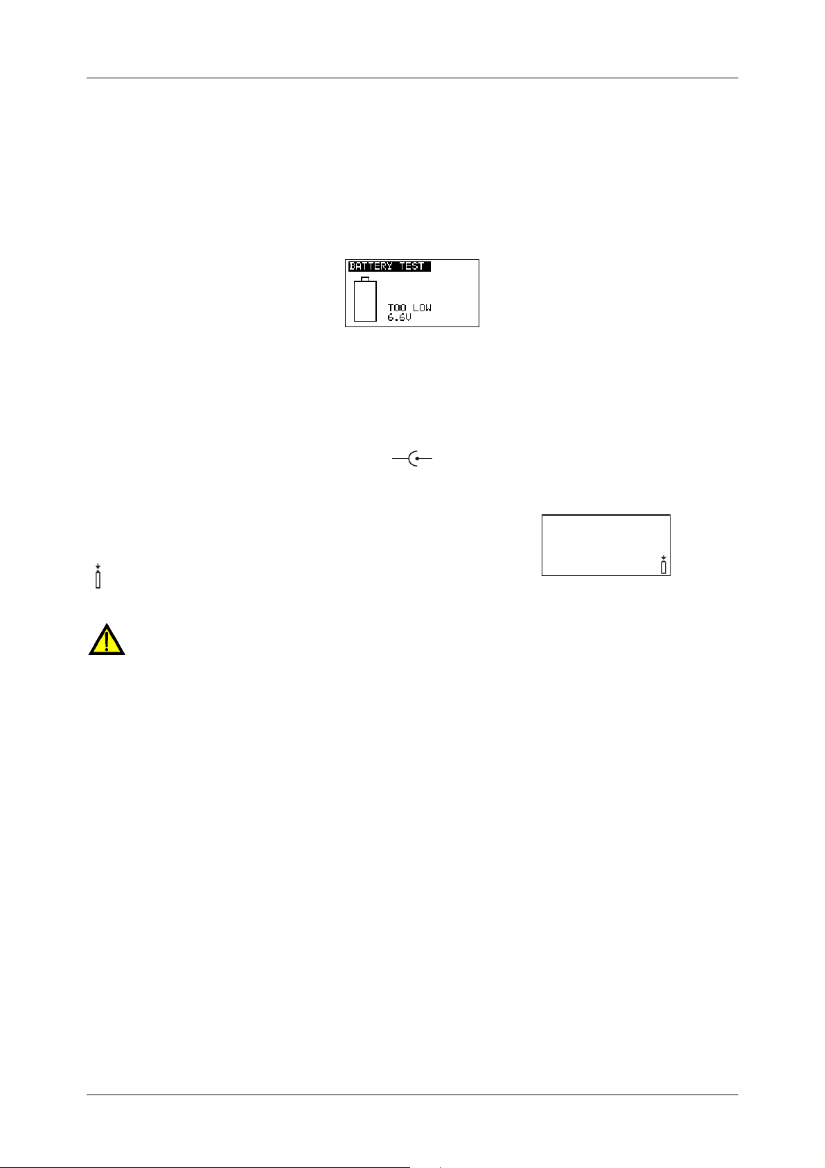
2.2 Batteries / storage batteries and charger
The installation tester can be operated with six alkaline batteries (type AA) or with rechargeable
NiMH batteries (storage batteries). The specified operating time refers to storage batteries with
a nominal capacity of 2100mAh. The batteries' state of charge is permanently displayed in the
lower right part of the LC display. If the battery voltage is too low, this will be displayed as
shown in figure 2.1. This indication is shown several seconds before the tester switches off.
Figure 2.1: Indication of discharged batteries
The rechargeable NiMH storage batteries will be charged automatically as soon as the charger
is connected with the charging jack of the installation tester. The polarity of the charging jack will
be displayed as shown in figure 2.2. An integrated protective circuit controls the charging
process and ensures an optimum battery lifetime.
Figure 2.2: Polarity of the charging jack
Symbol:
General warnings:
If the installation tester is connected to an installation, a dangerous voltage might be
applied to the battery compartment! Disconnect all test cables / accessories from the
installation tester and switch the installation tester off before replacing the batteries /
storage batteries and before opening the cover of the battery / fuse compartment!
Please make sure that the batteries / storage batteries are inserted correctly, because
otherwise the installation tester cannot be operated and the storage batteries will
discharge.
Do not recharge alkaline batteries!
Use only the charger included in the delivery!
Notes:
The charger inside the installation tester is a cell pack charger. This means that the
storage batteries are connected in series during charging. For this reason, the storage
batteries must be equivalent (same state of charge, same condition, same type and
same age).
If the installation tester is not used for a longer period of time, remove all storage
batteries from the battery compartment.
Use alkaline batteries or rechargeable NiMH batteries of size AA only! It is
recommended to use storage batteries with a minimum capacity of 2100 mAh.
Indication of the storage battery
charging process
Figure 2.3: Charging in progress
- 10 -

BENNING IT 115 Safety and operating instructions
Unpredictable chemical processes might occur during the charging of storage batteries
that have not been used for a longer period of time (more than 6 months). In this case, it
is recommended to repeat the charging / discharging cycle at least 2 to 4 times.
If no improvement is achieved after several charging / discharging cycles, every storage
battery should be tested individually (by comparing the storage battery voltages, testing
by means of a cell charger etc.). It is very likely that only some of the storage batteries
have lost capacity. If one storage battery differs from the other ones, this might affect the
correct functioning of the entire storage battery block!
The effects described above must not be confused with the normal battery capacity
decrease over time. All rechargeable batteries (storage batteries) lose some of their
battery capacity when being charged / discharged several times. This information is
provided in the technical data specified by the battery manufacturer.
- 11 -

BENNING IT 115 Safety and operating instructions
2.3 Standards applied
The BENNING IT 115 installation tester is manufactured and tested in compliance with the
following regulations:
Electromagnetic compatibility (EMC)
EN 61326-1 Electrical equipment for measurement, control and laboratory use
– EMC requirements
Class B (hand-held equipment in controlled EM environments)
Safety (LVD)
EN 61010-1 Safety requirements for electrical equipment for measurement, control and
laboratory use – Part 1: General requirements
EN 61010-2-030 Safety requirements for electrical equipment for measurement, control and
laboratory use – Part 2-030: Particular requirements for testing and
measuring circuits
EN 61010-031 Safety requirements for electrical equipment for measurement, control and
laboratory use – Part 031: Safety requirements for hand-held probe
assemblies for electrical measurement and test
EN 61010-2-032 Safety requirements for electrical equipment for measurement, control and
laboratory use – Part 2-032: Particular requirements for hand-held and
hand-manipulated current sensors for electrical test and measurement
Functionality
EN 61557 Electrical safety in low-voltage distribution systems up to 1000 VAC and
1500 VDC – Equipment for testing, measuring or monitoring of protective
measures
Part 1: General requirements
Part 2: Insulation resistance
Part 3: Loop impedance
Part 4: Resistance of earth connection and equipotential bonding
Reference standards for electrical installations and components
EN 61008 Residual current operated circuit-breakers without integral overcurrent
EN 61009 Residual current operated circuit-breakers with integral overcurrent
EN 60364-4-41 Low-voltage electrical installations – Part 4-41: Protection for safety –
BS 7671 IEE Wiring Regulations (17th edition)
AS / NZS 3017 Electrical installations – Verification guidelines
Note on EN and IEC standards:
This operating manual contains references to European standards. All standards of the
series EN 6XXXX (e.g. EN 61010) correspond to the respective IEC standards with the
same number (e.g. IEC 61010). They only differ in the modified parts due to the
European harmonization procedures.
Part 5: Resistance to earth
Part 6: Effectiveness of residual current devices (RCD) in TT, TN and IT
systems
Part 7: Phase sequence
Part 10: Combined measuring equipment for testing, measuring or
monitoring of protective measures
protection for household and similar uses (RCCBs)
protection for household and similar uses (RCBOs)
Protection against electric shock
- 12 -
BENNING IT 115 Device description
3 Device description
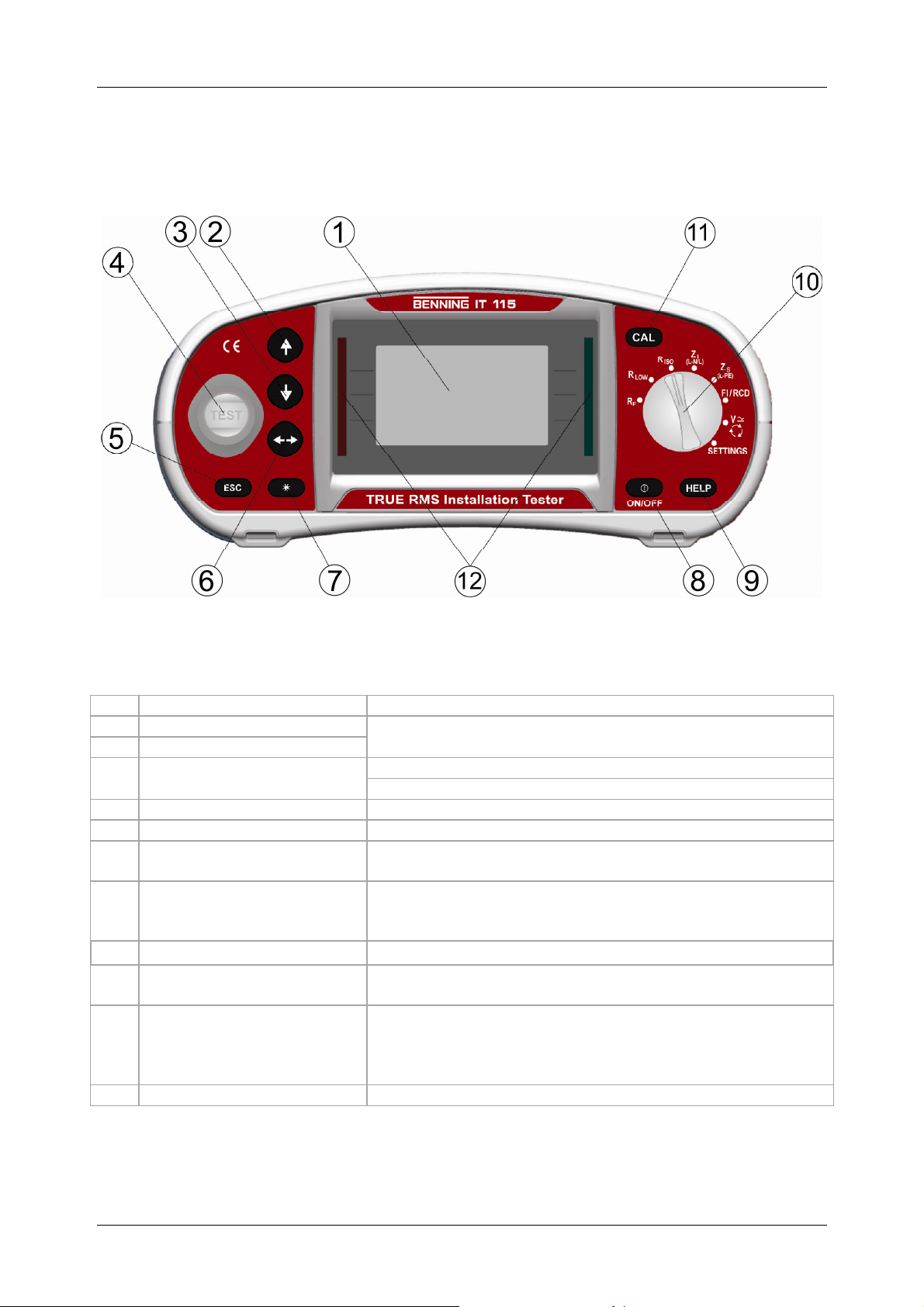
3.1 Front panel
Caption:
LCD
1
UP
2
DOWN
3
TEST
4
ESC
5
TAB
6
Backlight,
7
Contrast
ON / OFF
8
HELP
9
Function selector switch
10
CAL
11
Green / red LED
12
Figure 3.1: Front panel
Matrix display with 128 x 64 pixels and background lighting
Modifies selected parameters
Start of measurement
PE contact electrode for protective conductor connection
Back / cancel
Selects parameters in the measuring function selected
Modifies background lighting and contrast
Switches the tester on or off;
automatic switch-off ("APO") after 15 minutes without
pressing a key
Help function with connection diagrams
Rotary switch for selecting the measuring functions and
"SETTINGS" mode
For calibrating the test cables in the R LOW and
CONTINUITY function
Starts the Z
voltage drop
PASS / FAIL indication of the measuring results
measurement in the sub-function ∆U
REF
- 13 -
BENNING IT 115 Device description
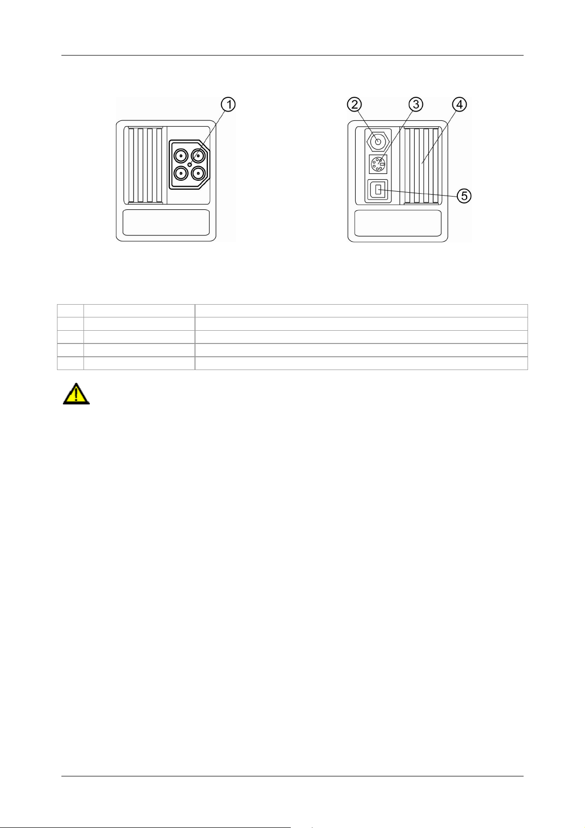
3.2 Connection panel
Caption:
Test connection
1
Charging jack
2
PS/2 port
3
Protective cover
4
USB port
5
Warnings!
The maximum admissible voltage between the testing terminals and earth is 550 V!
The maximum admissible voltage between the testing terminals is 550 V!
The maximum admissible short-term voltage of the external charger is 14 V!
Figure 3.2: Connection panel
Measuring inputs / outputs
For charging rechargeable NiMH storage batteries
Serial RS232 interface for service
Without function!
- 14 -
BENNING IT 115 Device description
3
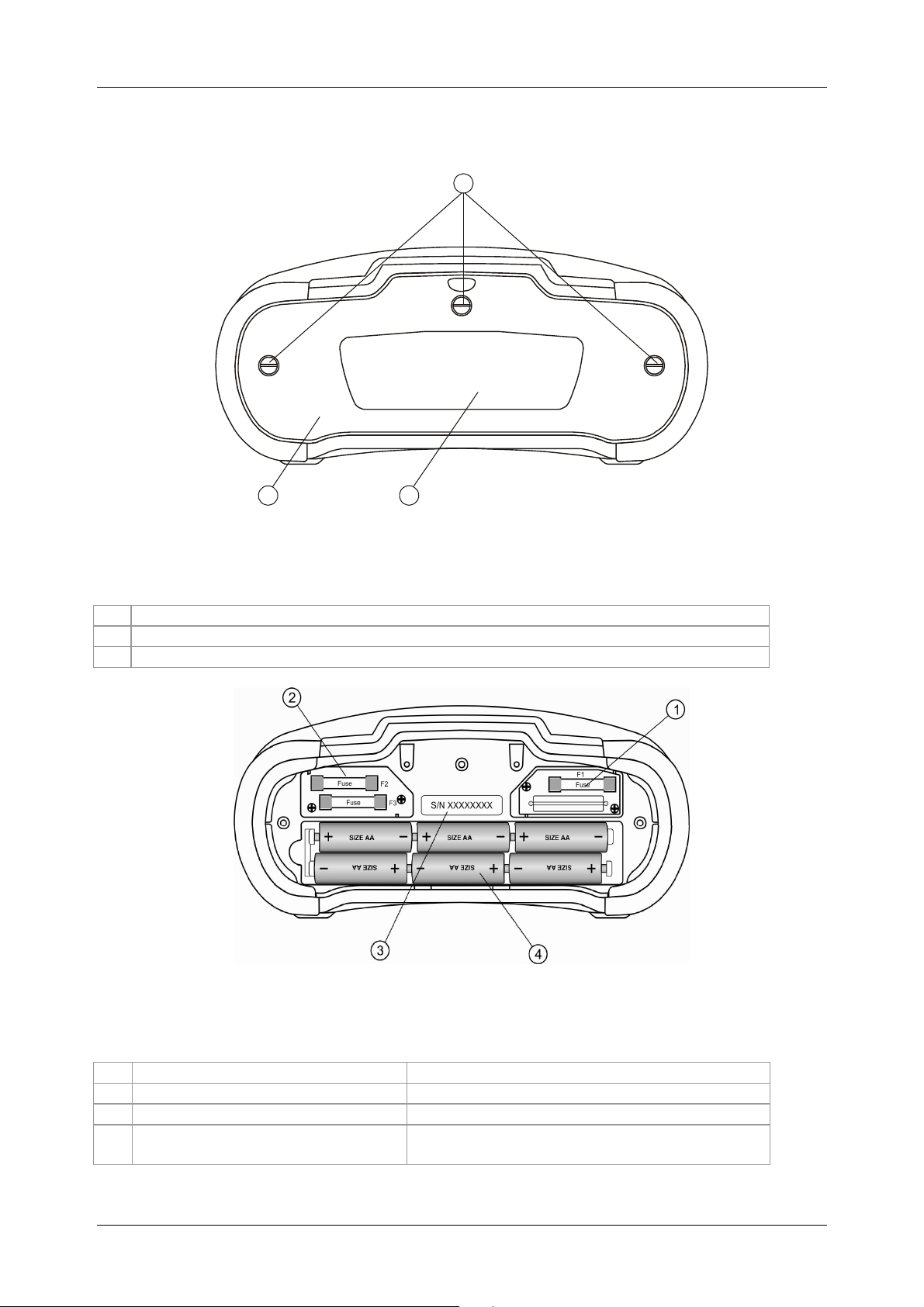
3.3 Rear panel
1
2
Figure 3.3: Rear panel
Caption:
Cover of the battery / fuse compartment
1
Information label
2
Screws for the battery / fuse compartment cover
3
Figure 3.4: Battery / fuse compartment
Caption:
Fuse F1
1
Fuses F2 and F3
2
Serial number label
3
Storage batteries / batteries
4
M 315 mA / 250 V
F 4 A / 500 V (breaking capacity 50 kA)
Size AA, alkaline / rechargeable NiMH,
quantity: 6 pieces
- 15 -
BENNING IT 115 Device description
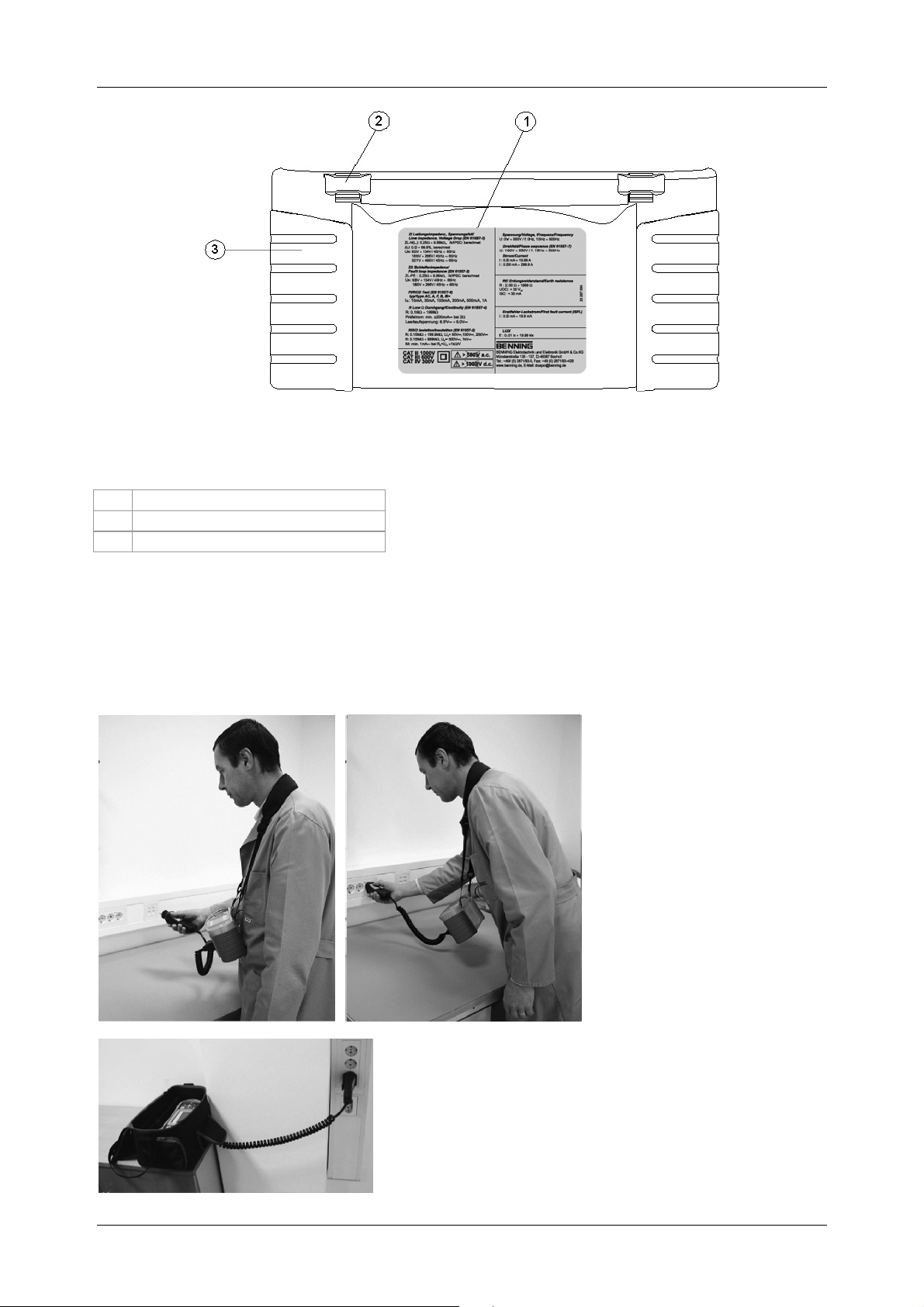
Figure 3.5: Bottom view
Caption:
Information label
1
Carrying strap openings
2
Lateral covers
3
3.4 Carrying the installation tester
The installation tester can be carried in different ways by means of the accessories included in
the standard scope of delivery.
The tester can be hung
around the operator's neck by
means of the carrying strap.
It is also possible to carry the tester in the padded carrying
case and to use it in a horizontal position. The carrying
case is provided with an aperture for passing through the
test cable.
- 16 -
BENNING IT 115 Device description
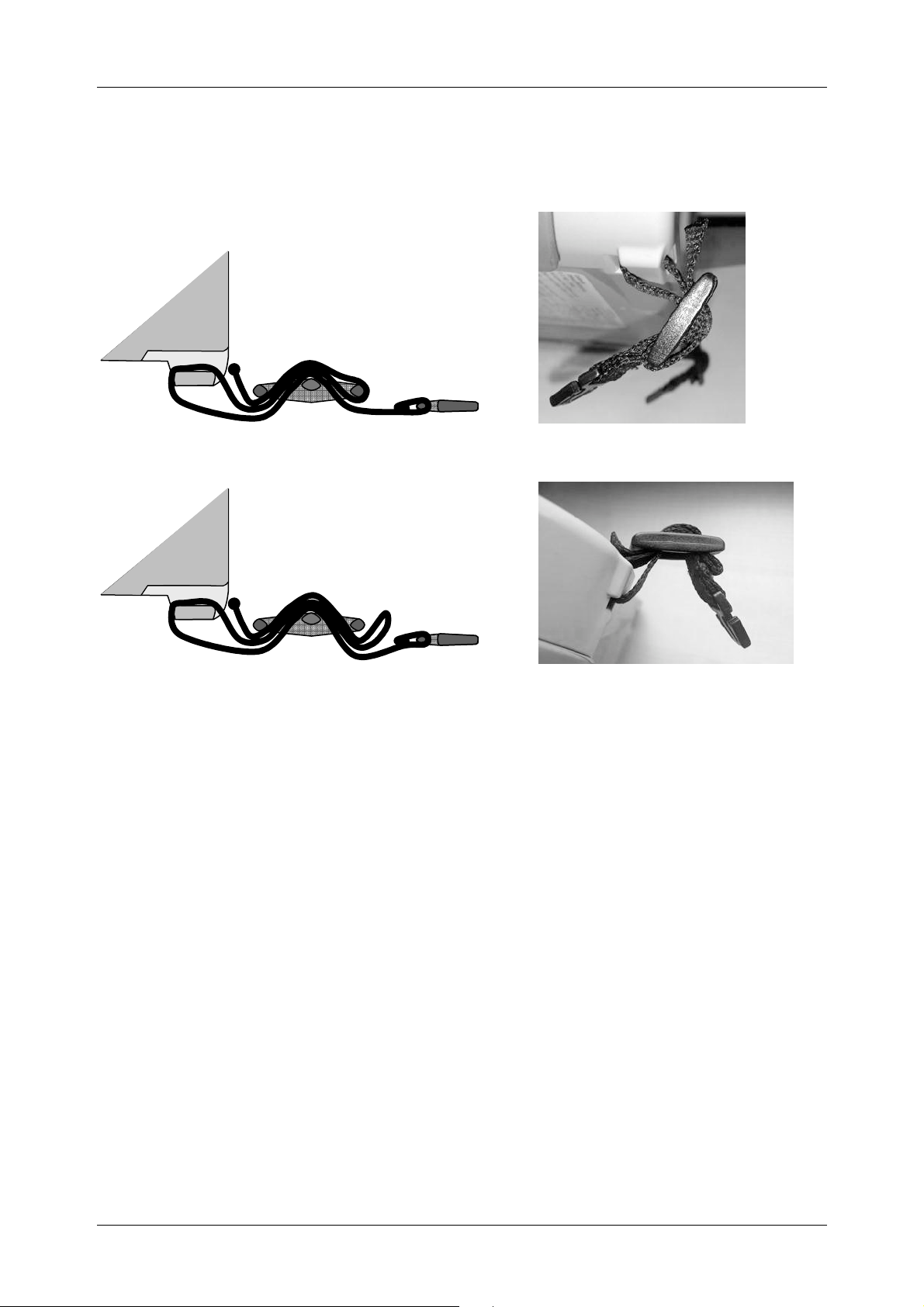
3.4.1 Attachment of the carrying strap
Please choose one of the two methods shown:
Figure 3.6: First method
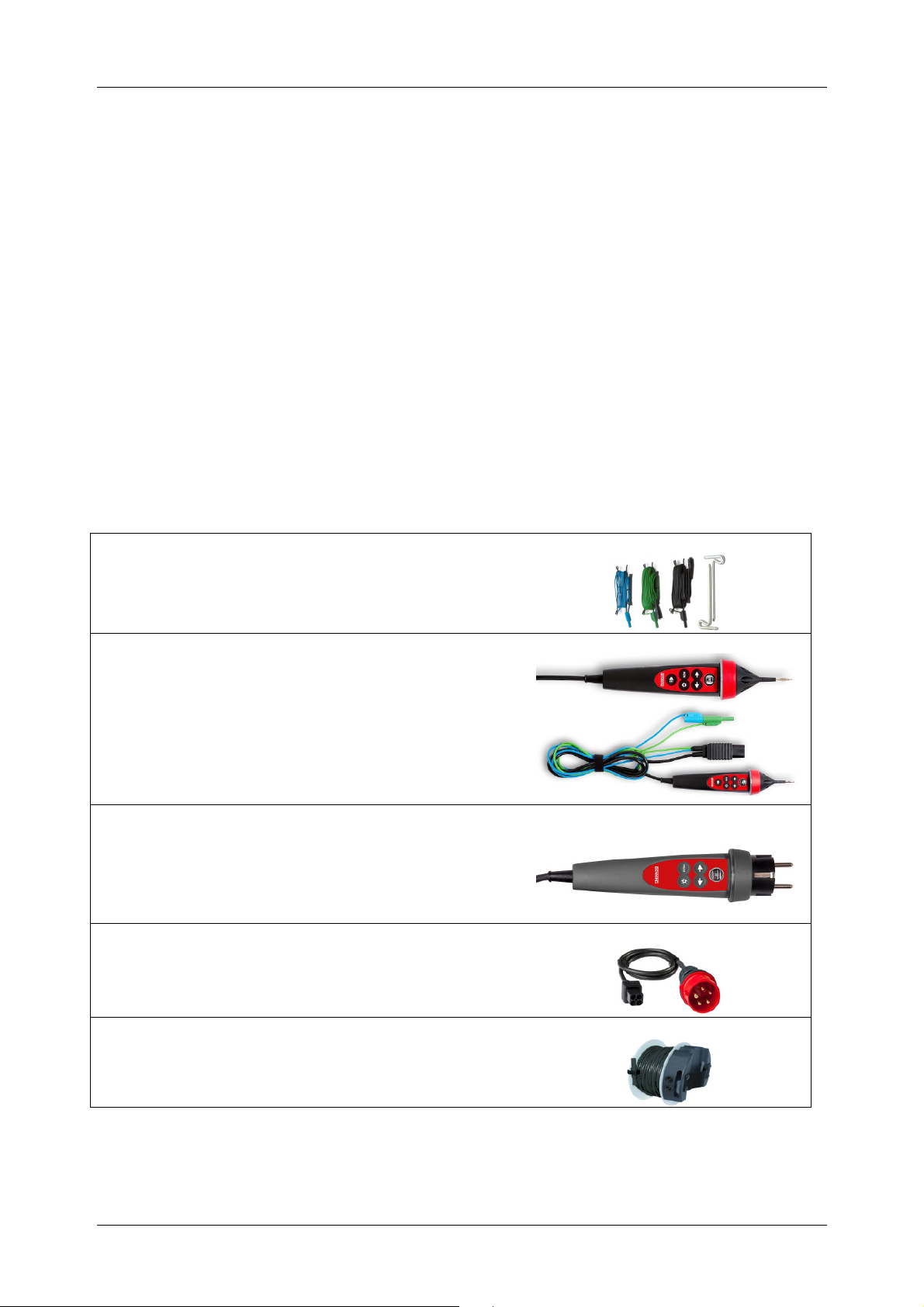
Figure 3.7: Alternative method
Please check the carrying strap for safe fastening regularly.
- 17 -
BENNING IT 115 Device description
3.5 Scope of delivery and optional accessories
3.5.1 Standard scope of delivery
1 x BENNING IT 115 installation tester
1 x padded carrying case
1 x test cable with shock-proof plug
1 x universal three-wire test cable (black, blue, green)
1 x set of test probes (black, blue, green)
1 x set of alligator clips (black, blue, green)
1 x carrying strap
6 x rechargeable NiMH storage batteries of size AA
1 x charger
1 x CD-ROM with operating manual and quick reference guide in PDF format
1 x quick reference guide
1 x calibration certificate
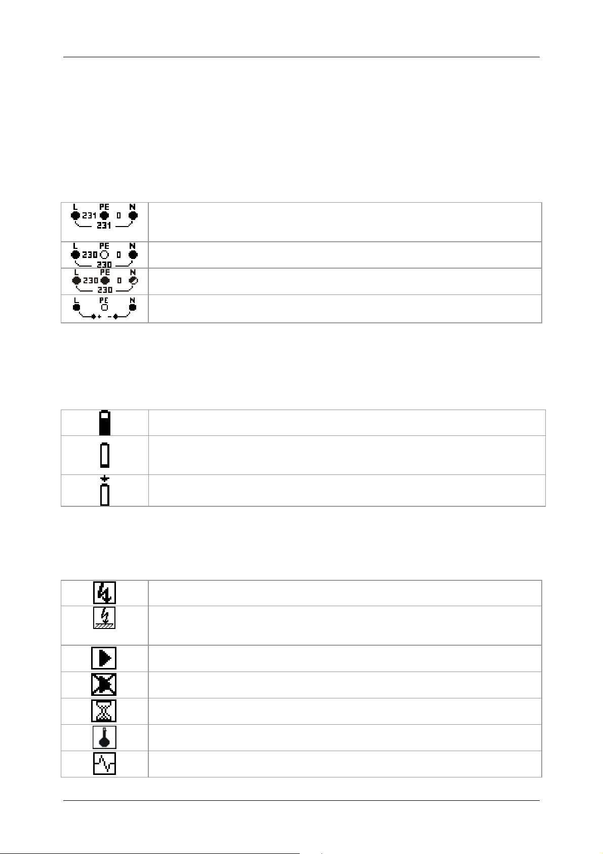
3.5.2 Optional accessories
Earthing kit
Earthing kit, 2 earth rods, 3 test cables,
2 x L = 20 m, 1 x L = 4.5 m Item no.: 044113
"Commander" test probe
“TEST“ key for releasing the measuring process,
“PASS“/“FAIL“ indication by means of green/ red LED,
PE contact electrode for detecting the phase voltage at
the protective conductor connection PE, key for
measuring point and LCD illumination Item no. 044155
"Commander" test plug
For shock-proof socket, switchable with "TEST" keys,
with "PASS" / "FAIL" indication by means of green/red
LED, PE contact electrode for detecting the phase
voltage at the protective conductor connection (PE).
Item no.: 044149
CEE measuring adapter
16 A, 5-pin, for measuring the voltage and phase
sequence (rotary field) at 16 A CEE sockets.
Item no.: 044148
Measuring line (40 m)
40 m measuring line with rewinder and wrist strap, for
measuring protective conductor connections.
Item no.: 044039
- 18 -
BENNING IT 115 Management of measured values
4 Operating the BENNING IT 115 installation tester
4.1 Indications and acoustic warning signals
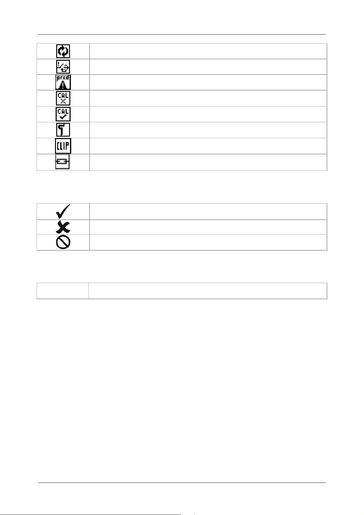
4.1.1 Connection monitor
The connection monitor shows the voltages applied to the testing terminals as well as
information on active testing terminals in the AC mains.
The voltage applied is displayed together with the testing terminal indication.
All three testing terminals L, N and PE are used for the selected
measurement.
The voltage applied is displayed together with the testing terminal indication.
The testing terminals L and N are used for the selected measurement.
The testing terminals L and PE are active testing terminals. The testing
terminal N should be connected as well to show a correct input voltage.
The polarity of the testing voltage applied (R LOW, R ISO) is displayed at the
output terminals L and N.
4.1.2 Battery indication
The battery indication shows the current state of charge of the storage battery as well as
whether an external charger is connected.
Battery capacity indication
Low state of charge.
The storage battery's state of charge is too low to ensure correct measuring
results. Replace the batteries or recharge the storage batteries.
Charging in progress (with the charger being connected)
4.1.3 Warnings and messages
The following warnings and messages are displayed:
Warning! High voltage is applied to the testing terminals.
Warning! Dangerous voltage at the PE connection! Immediately stop the
measuring process and eliminate the fault / the connection problem before
continuing with the measurement!
The conditions at the input terminals allow starting the measurement. Please
observe further warnings and messages!
The conditions at the input terminals do not allow starting the measurement.
Please observe further warnings and messages!
Measurement is in progress. Please observe warnings that might be
displayed!
The tester is overheated. Measurements are interrupted until the internal
temperature has dropped below the admissible limiting value.
A high interference voltage has been detected during measurement. This
might result in incorrect measuring results.
- 19 -
BENNING IT 115 Device description
L and N have been interchanged.
RCD has been tripped during measurement (in RCD functions).
Portable RCD (PRCD) has been selected (only for documentation purposes).
The test cable resistance for low-impedance measurement / continuity test
has not been compensated.
The test cable resistance for low-impedance measurement / continuity test
has been compensated.
High earthing resistance of the measuring probes. This might result in
incorrect measuring results.
The measuring signal is outside the measuring range This might result in
incorrect measuring results.
Fuse F1 is defective.
4.1.4 Evaluation field
The measuring result is within the preset limiting values (green LED).
The measuring result is outside the preset limiting values (red LED).
Measurement has been aborted. Please observe the warnings and messages
displayed.
4.1.5 Acoustic warning signals
Continuous
sound
Warning! Dangerous voltage at the PE connection!
- 20 -
BENNING IT 115 Device description
4.1.6 Help menu ("HELP" key)
HELP
Opens the help menu.
Help menus are available for all measuring functions. The help menu contains graphic
connection diagrams showing how to connect the installation tester to the electrical installation.
After having selected the desired measuring function, press the "HELP" key to view the
corresponding help menu.
Keys used in the help menu
UP / DOWN
Selects the next / previous connection diagram
ESC / HELP /
function selector switch
Use these keys to exit the help menu.
Figure 4.1: Connection diagrams of the help menu
4.1.7 Background lighting and contrast
Use the key for background lighting and contrast to make the following settings:
Briefly press the key
Press and hold the key for
1 second
Press and hold the key for
2 seconds
Activates the background lighting for approx. 10 seconds
Switches the background lighting on permanently until the tester
switches off or the key is pressed again
Allows to set the LCD contrast
Keys used for contrast setting
UP
DOWN
TEST
ESC
Increases the contrast
Reduces the contrast
Applies the adjusted contrast
Exits the settings without any changes
Figure 4.2: LCD contrast setting
- 21 -

BENNING IT 115 Device description
4.2 Function selector switch
The function selector switch is intended for selecting the
test and measuring functions
"SETTINGS" mode
Key functions after having selected the test / measuring function:
UP / DOWN
TAB
TEST
ESC
Key functions in the Parameters field:
UP / DOWN
TAB
Parameters and limiting values for evaluating the measuring results:
Parameter,
limiting value
WITHOUT
ON
Please find further information on how to use the test / measuring functions of the installation
tester in chapter 5. Measurements.
Selects the sub-function of the adjusted test / measuring function
(only for rotary switch positions R
, ZI, ZS, FI/RCD)
LOW
Selects the parameters and limiting values
Start of measurement
Back / cancel
Modifies the selected parameter
Selects the next parameter
No parameters / limiting values, indication: _ _ _.
Measuring results – will be marked as "PASS" / "FAIL" according to
the parameters and limiting values set
- 22 -

BENNING IT 115 Device description
4.3 "SETTINGS" mode
Turn the measuring function selector switch to the "SETTINGS" mode in order to make the
following settings at the tester:
SELECT LANGUAGE (GB, D, E, F, NL)
RCD TESTING (according to EN 61008 / EN 61009,
IEC 60364-4-41, BS 7671, AS/NZS 3017)
SET ISC FACTOR (0.20 - 3.00)
COMMANDER ON/OFF
INITIAL SETTINGS (reset to factory settings)
Keys used:
UP / DOWN
TEST
ESC / function selector
switch
Figure 4.3:
"SETTINGS" mode
Selects the respective option
Confirms the selected option
Back / cancel without any changes
4.3.1 Language
In this menu, it is possible to select the respective
language.
Keys used:
UP / DOWN
TEST
ESC
Function selector switch
Selects the language
Confirms the selected language and returns to the Settings menu
Back / cancel to the Settings menu
Back / cancel to the selected measuring function
4.3.2 RCD testing
In this menu, it is possible to set the standard used for RCD
testing.
Figure 4.4:
Selecting the language
Figure 4.5:
Selecting the RCD standard
Keys used:
UP / DOWN
TEST
ESC
Function selector switch
Selects the standard
Confirms the selected standard and returns to the Settings menu
Back / cancel to the Settings menu
Back / cancel to the selected measuring function
- 23 -

BENNING IT 115 Device description
S
The maximum RCD tripping times vary from standard to standard.
The times specified in the individual standards are listed in the following.
By default, the tripping times in compliance with the EN 60364-4-41 standard are preset. The
EN 60364-4-41 standard defines different tripping times for TN/IT networks and TT networks as
can be seen in table 41.1.
Tripping times in compliance with EN 60364-4-41:
Uo
TN/IT
TT
≤120 V
≤230 V
≤120 V
≤230 V
t∆ > 800 ms t∆ ≤ 800 ms
t∆ > 400 ms t∆ ≤ 400 ms
t∆ > 300 ms t∆ ≤ 300 ms
t∆ > 200 ms t∆ ≤ 200 ms
½×I
*)
I∆N 2×I∆N 5×I∆N
∆N
t∆ < 150 ms t∆ < 40 ms
Uo: Nominal voltage of external conductor to earth
Example of a tripping time evaluation for I∆N, Uo: ≤230 V
Setting Tripping time
IEC 60364-4-41 TN/IT < 400 ms
400 ms <
t
> 999 ms
IEC 60364-4-41 TT < 200 ms
200 ms <
t
> 999 ms
t
Evaluation field
∆
< 999 ms
∆
< 999 ms
∆
Tripping times in compliance with EN 61008/EN 61009:
Standard RCDs
(undelayed)
Selective RCDs
(delayed)
*)
½×I
t∆> 300 ms t∆< 300 ms t∆< 150 ms t∆< 40 ms
t∆> 500 ms 130 ms< t∆< 500 ms 60 ms< t∆< 200 ms 50 ms< t∆< 150 ms
I∆N 2×I∆N 5×I∆N
∆N
Tripping times in compliance with BS 7671:
Standard RCDs
(undelayed)
Selective RCDs
(delayed)
Tripping times in compliance with AS/NZS 3017
RCD type
I
II
I∆N [mA] t∆ t∆ t∆ t∆
≤ 10
> 10 ≤ 30
III > 30
IV
*)
Minimum testing time for a current of ½×I∆N, RCD must not trip
**)
Testing current and measuring accuracy correspond to the requirements specified by
> 30 > 999 ms
*)
½×I
t∆> 1999 ms t∆< 300 ms t∆< 150 ms t∆< 40 ms
t∆> 1999 ms 130 ms< t∆< 500 ms 60 ms< t∆< 200 ms 50 ms< t∆< 150 ms
I∆N 2×I∆N 5×I∆N
∆N
**)
:
½×I
*)
I∆N 2×I∆N 5×I∆N
∆N
Remark
40 ms 40 ms 40 ms
> 999 ms
300 ms 150 ms 40 ms
300 ms 150 ms 40 ms
maximum tripping time
500 ms 200 ms 150 ms
130 ms 60 ms 50 ms minimum non-tripping time
AS/NZS 3017
- 24 -

BENNING IT 115 Device description
Maximum testing times and selected testing current for standard (undelayed) RCDs:
Standard
EN 60364-4-41 1000 ms
EN 61008 / EN 61009 300 ms
BS 7671 2000 ms
AS/NZS 3017 (I, II, III) 1000 ms
½×I∆N I∆N 2×I∆N 5×I∆N
1000 ms
300 ms
300 ms
1000 ms
150 ms
150 ms
150 ms
150 ms
40 ms
40 ms
40 ms
40 ms
Maximum testing times and selected testing current for selective (delayed) RCDs:
Standard
EN 60364-4-41 1000 ms
EN 61008 / EN 61009 500 ms
BS 7671 2000 ms
AS / NZS 3017 (IV) 1000 ms
½×I∆N I∆N 2×I∆N 5×I∆N
1000 ms
500 ms
500 ms
1000 ms
200 ms
200 ms
200 ms
200 ms
150 ms
150 ms
150 ms
150 ms
4.3.3 Isc factor (scaling factor)
In this menu, it is possible to set the Isc factor
(scaling factor) for calculating the short-circuit
current (Ik) in the functions ZI (L-N/L) and Zs
(L-PE).
Figure 4.6:
Selecting the Isc factor
Keys used:
UP / DOWN
TEST
ESC
Function selector switch
Modifies the Isc factor
Confirms the adjusted Isc factor
Back / cancel to the Settings menu
Back / cancel to the selected measuring function
The short-circuit current Ik in the power supply system is of particular importance for the
selection and testing of protective circuits (fuses, overcurrent protection devices, RCDs).
The default value of the Isc factor (Ik) is 1.00. The value has to be set according to local
requirements.
The Isc factor can be set within the range of 0.20 ÷ 3.00.
4.3.4 Commander ON/OFF
In this menu, it is possible to enable or disable
the optional "Commander".
Keys used:
UP / DOWN
TEST
ESC
Function selector switch
Figure 4.7:
Selecting the "Commander" support
Selects Commander ON (enabled) / Commander OFF (disabled)
Confirms the selected option
Back / cancel to the Settings menu
Back / cancel to the selected measuring function
- 25 -

BENNING IT 115 Device description
Note:
The "Commander OFF" (disabled) option is intended for deactivating the operating keys
of the "Commander" (except for the background lighting key). It is useful to disable the
"Commander", if strong sources of interference might affect the correct functioning of the
"Commander".
4.3.5 Initial settings
In this menu, it is possible to reset the settings,
measuring parameters and limiting values of the
installation tester to their initial (factory) settings.
Keys used:
UP / DOWN
TEST
ESC
Function selector
Selects the option [YES, NO]
Confirms the selected option
Back / cancel to the Settings menu
Back / cancel to the selected measuring function
switch
Note:
If the tester is reset to its initial (factory) settings, all settings made will be lost!
If the batteries are removed for more than 1 minute, all settings made will be lost.
The initial (factory) settings are defined as follows:
Settings of the tester Default setting
Language German
Contrast 50 %
Earthing system TN / TT
Isc factor 1.00
RCD standards EN 60364-4-41
"Commander" test probe (optional) ON
Measuring function
Sub-function
Parameter / limiting value
RE No limiting value
R ISO without limiting value,
nominal testing voltage: 500 V
R LOW No limiting value
CONTINUITY No limiting value
ZI (L-N/L) line impedance Fuse type: none selected
∆U voltage drop ∆U: 4.0 %, Z
: 0.00 Ω
REF
Zs (L-PE) loop impedance Fuse type: none selected
Zsrcd Fuse type: none selected
Figure 4.8:
Initial settings dialog
- 26 -

BENNING IT 115 Device description
RCD RCD t
Nominal differential current: I∆N=30 mA
RCD type: AC, undelayed
Testing current with initial polarity: (0°)
Limiting value for contact voltage: 50 V
Nominal differential current multiplier: ×1
Note:
It is also possible to reset the tester to its initial (factory) settings by pressing the "TAB"
key when simultaneously switching the tester on.
- 27 -

BENNING IT 115 Device description
5 Measurements
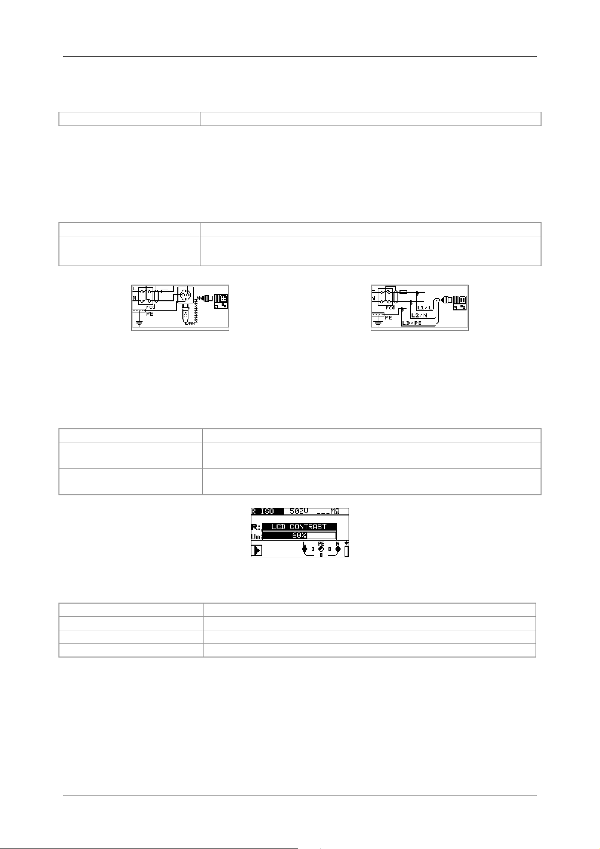
5.1 TRMS voltage, frequency and phase sequence
The voltages applied to the testing terminals are permanently displayed by means of the
connection monitor. In the VOLTAGE TRMS measuring range (true RMS voltage value), the
measured values for voltage (AC/DC) and frequency as well as the phase sequence (rotary
field) detected can be saved. The measurements are carried out in compliance with the
EN 61557-7 standard.
Key function as described in chapter
4.2 Function selector switch
Testing parameters
It is not necessary to set any parameters.
Connection plan
Figure 5.1:
Voltage in a single-phase system
Figure 5.2: Connection of the three-wire test cable and the
optional CEE measuring adapter (044148) in a three-phase system
Figure 5.3: Connection of the optional "Commander" test plug (044149) and the three-wire test
cable in a single-phase / three-phase system
- 28 -

BENNING IT 115 Device description
How to perform voltage measurements
Select the
V≅≅≅≅
function by means of the function selector switch. The display shows
VOLTAGE TRMS.
Connect the test cables to the test object (see figure 5.2 and figure 5.3).
The measurement is performed immediately after the VOLTAGE TRMS function has been
selected.
Figure 5.4: Examples for voltage measurements in single-phase and three-phase systems
Results displayed for single-phase systems:
Uln ........... voltage between phases and neutral conductor
Ulpe ......... voltage between phase and protective conductor
Unpe ........ voltage between neutral and protective conductors
f................ frequency
Results displayed for three-phase systems:
U12........... voltage between testing terminals L1 and L2
U13........... voltage between testing terminals L1 and L3
U23........... voltage between testing terminals L2 and L3
1.2.3 ......... correct connection – clockwise phase sequence
3.2.1 ......... wrong connection – counter-clockwise phase sequence
f................ frequency
Results displayed for IT systems:
U12........... voltage between testing terminals L1 and L2
U1pe ........ voltage between testing terminals L1 and PE
U2pe ........ voltage between testing terminals L2 and PE
f................ frequency
- 29 -

BENNING IT 115 Device description
5.2 Insulating resistance
The measurement of the insulating resistance is performed in order to prove the proper
condition of the insulation and in order to exclude electrical danger.
Typical applications are the following cases:
Insulating resistance between the active conductors (L/N) of an installation and the
protective conductor / earth (PE) => protection against electric shock,
Insulating resistance between the active conductors (L/N) of an installation => protection
against short-circuit (over-current) and guarantee of the functional safety,
Insulating resistance of non-conductive rooms (walls and floors),
Insulating resistance of earthing cables and
Resistance of semiconductive (antistatic) floors.
Key function as described in chapter
4.2 Function selector switch
Figure 5.5:
Insulating resistance
Testing parameters
Uiso Nominal testing voltage [50 V, 100 V, 250 V, 500 V, 1000 V]
Limiting value
Minimum insulating resistance [without limits (---), 0.01 MΩ ÷ 200 MΩ]
Connection plan
Figure 5.6: Connection of the three-wire test cable and
the optional "Commander" test probe (044155)
- 30 -

BENNING IT 115 Device description
How to perform insulating resistance measurements
Select the R
Set the required testing voltage and the limiting value (optional).
Make sure that the test object is free of voltage and discharge available capacities.
Connect the test cables to the test object (see figure 5.6).
Press the "TEST" key to start the measurement. Double-click the "TEST" key (MΩ flashes)
function by means of the function selector switch.
ISO
to perform a continuous measurement. Press the key again to finish the measurement.
After measurement, wait until the test object is completely discharged.
Figure 5.7: Example of an insulating resistance measurement
Results displayed:
R .............. insulating resistance
Um ........... testing voltage (actual value)
Attention:
Measurements of the insulating resistance must be carried out only at test objects which
are free of voltage!
Disconnect all loads and close all switches for measuring the insulating resistance
between conductors of the installation.
Do not touch the test object during measurement and before it is completely discharged!
There is danger of a life-threatening electric shock!
If the insulating resistance measurement is carried out on a capacitive object, automatic
discharging might take place time-delayed. The warning symbol and the actual voltage
will be displayed during discharging.
Do not connect the test cables to external voltages higher than 550 V (AC or DC) in
order not to damage the BENNING IT 115 installation tester!
- 31 -

BENNING IT 115 Device description
5.3 Low-impedance resistance / continuity test
The measurement of the low-impedance resistance / continuity test is intended for testing the
protective conductor, earthing conductor and equipotential bonding conductor connections of an
electrical installation.
Two sub-functions are available:
R LOWΩ – resistance measurement in compliance with EN 61557-4 with a testing
current of 200 mA and polarity reversal
CONTINUITY – continuous continuity test with a reduced testing current of 7 mA.
Key function as described in chapter
4.2 Function selector switch
Testing parameters
Test Sub-function [R LOWΩ, CONTINUITY]
Limiting value Maximum resistance [without limits (---), 0.1 Ω ÷ 20.0 Ω]
Additional testing parameter for continuity test sub-function:
Buzzer ON (sounds if the resistance is lower than the limiting value set) or OFF
Figure 5.8: Low-impedance
resistance RLOW Ω with a testing
current of 200 mA
5.3.1 Low-impedance resistance with a testing current of 200 mA
The resistance measurement is performed with automatic polarity reversal of the testing
voltage.
Connection plan
Figure 5.9: Connection of the three-wire test cable and the
optional 40 m measuring line BENNING TA 5 (044039)
- 32 -

BENNING IT 115 Device description
How to perform low-impedance measurements R LOWΩ
Select the R
Set the sub-function to R LOWΩ.
Set the limiting value (optional).
Connect the test cables to the installation tester and compensate the test cable
function by means of the function selector switch.
LOW
resistance, if necessary (see section 5.3.3 Compensation (null balance) of the test cable
resistance).
Make sure that the test object is free of voltage and discharge available capacities.
Connect the test cables to the test object (see figure 5.9).
Press the "TEST" key to start the measurement.
Figure 5.10: Example of a low-impedance measurement RLOWΩ
Results displayed:
R .............. R LOWΩ – low-impedance resistance
R+ ............ partial result at positive polarity
R- ............. partial result at negative testing polarity
5.3.2 Continuity test with a testing current of 7 mA
This test function can be compared to the continuity test function of a digital multimeter or of a
continuity tester with low testing current. The continuous test is done without polarity reversal
and can be used for testing inductive components.
Connection plan
Figure 5.11: Using the optional "Commander" test probe and the three-wire test cable
- 33 -

BENNING IT 115 Device description
How to perform continuity tests
Select the R
Set the sub-function to CONTINUITY.
Set the limiting value (optional).
Connect the test cables to the installation tester and compensate the test cable resistance,
function by means of the function selector switch.
LOW
if necessary (see section 5.3.3 Compensation (null balance) of the test cable resistance).
Make sure that the test object is free of voltage and discharge available capacities.
Connect the test cables to the test object (see figure 5.11).
Press the "TEST" key to start the measurement.
Press the "TEST" key again to stop the measurement.
Figure 5.12: Example of a continuity test
Result displayed:
R .............. resistance
5.3.3 Compensation (null balance) of the test cable resistance
This chapter describes how to compensate the test cable resistance in the low-impedance
measurement (R LOWΩ) and continuity test (CONTINUITY) functions. Compensation is
necessary, because the test cable resistance and the internal resistance of the installation
tester might influence the measuring result. The compensation of the test cables is particularly
required when using measuring lines of different lengths.
The icon is displayed, if the test cable resistance has been compensated successfully.
Connection plan
Figure 5.13: Shorted three-wire test cable and optional “Commander” test probe (044155)
How to carry out compensation
Select the R LOWΩ or CONTINUITY function.
Connect the test cables to the installation tester and short-circuit the test cables (see figure
5.13.)
Press the "TEST" key to perform the resistance measurement.
Press the "CAL" key to compensate the test cable resistance.
Figure 5.14: Result before calibration Figure 5.15: Result after calibration
- 34 -

BENNING IT 115 Device description
Note:
The highest value for test cable compensation is 5 Ω. If the resistance is higher, the
compensation value will be reset to the default value.
The icon is displayed, if the test cable resistance has not been compensated.
- 35 -

BENNING IT 115 Device description
5.4 RCD testing
The testing of RCDs in RCD-protected installations requires various tests and measurements.
The measurements are based on the EN 61557-6 standard.
The following measurements and tests can be performed:
Contact voltage, tripping time, tripping current and
Automatic RCD testing
Key function as described in chapter
4.2 Function selector switch
Testing parameters
Test Sub-function [Uc, RCDt, RCD I, AUTO]
I
Nominal tripping differential current I
∆∆∆∆N
∆∆∆∆N
[10 mA, 30 mA, 100 mA, 300 mA, 500 mA, 1000 mA]
RCD
type
Type [AC, A, F]
Initial polarity [ , , , ]
Properties
[selective , standard undelayed , PRCD, PRCD-S, PRCD-K]
MUL
Multiplier of testing current [½x, 1x, 2 x, 5xI∆N]
Ulim Limiting value of contact voltage [25 V, 50 V]
Note:
The limiting value of the contact voltage can be set only in the Uc sub-function.
Selective (delayed) RCDs have delayed tripping times. As the contact voltage
measurement and other RCD tests influence delayed RCDs, it takes a certain time until
they have returned to their normal condition. For this reason, a time delay of 30 seconds
is added before the standard tripping test is performed.
During testing of some portable PRCDs (e.g. PRCD-K) in which the protective conductor
is guided through the converter in opposite direction, this portable RCD trips already at
the 0.5-fold value of the nominal tripping differential current. The installation tester
evaluates the early tripping as "accidental tripping" and aborts the test without any
measuring result. If this test has been carried out with a positive result, i.e. it has been
proven that the portable PRCD trips at the 0.5-fold value of the nominal tripping
differential current and thus the protective conductor is not interrupted, it is possible to
continue the test by changing the contacting of the protective conductor. In this case, it
is necessary to establish a contact to the protective conductor (PE) of an adjacent
socket instead of establishing a contact to the protective conductor (PE) of the coupling
socket for further testing. Then, the test can be performed just as for an ordinary RCD.
Figure 5.16:
RCD tests
- 36 -

BENNING IT 115 Device description
Connection plan
Figure 5.17: Connection of the optional "Commander" test plug (044149)
and the three-wire test cable
5.4.1 Contact voltage (Uc)
Leakage current flowing to earth via the protective conductor connection causes a voltage drop
at the earthing resistance, i.e. a voltage difference between the PE equipotential bonding and
earth. This voltage difference is called contact voltage and is applied to all accessible
conductive parts connected to protective earth (PE). The contact voltage always should be
lower than the maximum admissible contact voltage. Contact voltage is measured with a testing
current lower than ½ I∆N in order to avoid tripping of the RCD and then to be normalized to the
nominal value I
How to perform contact voltage measurements
Select the FI/RCD function by means of the function selector switch.
Set the sub-function to Uc.
Set the testing parameters.
Connect the test cables to the test object (see figure 5.17).
Press the "TEST" key to start the measurement.
The contact voltage displayed refers to the rated differential current of the RCD and is
multiplied with an appropriate factor for safety reasons.
avoid a negative tolerance of the result.
calculated.
The loop resistance is a purely indicative value and is calculated from the contact voltage
(without additional proportional factors).
.
∆
N
RCD type
AC
AC
A, F
A, F
A, F
A, F
The factor 1.05 is applied in order to
Table 5.1 describes how the contact voltage is
Contact voltage Uc
proportional to
1.05×I∆N
2×1.05×I∆N
1.4×1.05×I∆N
2×1.4×1.05×I∆N
2×1.05×I∆N
2×2×1.05×I∆N
Table 5.1: Relation between Uc and I
U
C
.
=
R
L
I
N
∆
Nominal value I
any
≥ 30 mA
<30 mA
∆
N
∆∆∆∆N
- 37 -

BENNING IT 115 Device description
Figure 5.18: Example of a contact voltage measurement
Results displayed:
Uc ........contact voltage
RL ........loop resistance (fault loop resistance)
5.4.2 Tripping time (RCDt)
The tripping time measurement serves to test the sensitivity of the residual current protection
devices (RCDs) at different nominal tripping differential currents I∆N.
How to perform tripping time measurements
Select the FI/RCD function by means of the function selector switch.
Set the sub-function to RCDt.
Set the testing parameters.
Connect the test cables to the test object (see figure 5.17).
Press the "TEST" key to start the measurement.
Figure 5.19: Example of a tripping time measurement
Result displayed:
t............tripping time
Uc ........contact Voltage
5.4.3 Tripping current (RCD I)
For tripping current measurement, a continuously increasing fault current serves to determine
the limiting sensitivity for RCD tripping. The installation tester increases the fault current in small
steps within the whole range as follows:
RCD type
AC
A, F (I
A, F (I
≥≥≥≥ 30 mA)
∆∆∆∆N
= 10 mA)
∆∆∆∆N
Increasing fault current
Initial value Final value
0,2×I∆N 1,1×I∆N
0,2×I∆N 1,5×I∆N
0,2×I∆N 2,2×I∆N
The maximum testing current is I∆ (tripping current) or corresponds to the final value, if the RCD
does not trip.
How to perform tripping current measurements
Select the FI/RCD function by means of the function selector switch.
Set the sub-function to RCD I.
Set the testing parameters.
Connect the test cables to the test object (see figure 5.17).
Press the "TEST" key to start the measurement.
Curve
shape
sinusoidal
pulsating
- 38 -

BENNING IT 115 Device description
Figure 5.20: Example of a tripping current measurement
Results displayed:
I ...........tripping current
Uci .......contact voltage at tripping current I or final value, if RCD does not trip
t............tripping time
5.4.4 Automatic test
The automatic RCD test is intended to perform a complete RCD test (tripping time at different
fault currents, tripping current and contact voltage) in a sequence of automatic tests controlled
by the installation tester.
Additional key
HELP / DISPLAY As soon as measurement is finished, the "HELP" key toggles between
the upper and lower part of the result field.
How to perform an automatic test
Steps of the automatic test Note
Select the FI/RCD function by means of the function selector
switch.
Set the sub-function to AUTO.
Set the testing parameters.
Connect the test cables to the test object (see figure 5.17).
Press the "TEST" key to start the measurement.
Testing with I∆N, 0° (step 1)
Activating the RCD
Testing with I∆N, 180° (step 2)
Activating the RCD
Testing with 5×I∆N, 0° (step 3)
Activating the RCD
Testing with 5×I∆N, 180° (step 4)
Activating the RCD
Testing with ½×I∆N, 0° (step 5)
Testing with ½×I∆N, 180° (step 6)
Tripping current test, 0° (step 7)
Activating the RCD
Tripping current test, 180° (step 8)
Activating the RCD
End of test
Start of test
RCD should trip
RCD should trip
RCD should trip
RCD should trip
RCD must not trip
RCD must not trip
RCD should trip
RCD should trip
- 39 -

BENNING IT 115 Device description
Example of the test steps:
Step 1
Step 3
Step 5
Step 7
Figure 5.21: Test steps of the automatic test
Step 2
Step 4
Step 6
Step 8
Top
Figure 5.22: The "HELP" key toggles between the upper
and the lower part of the result field.
Results displayed:
x1 .........step 1 tripping time (I∆=I∆N, 0º)
x1 .........step 2 tripping time (I∆=I∆N, 180º)
x5 .........step 3 tripping time (I∆=5×I∆N, 0º)
x5 .........step 4 tripping time (I∆=5×I∆N, 180º)
x½........step 5 tripping time (I∆=½×I∆N, 0º)
x½........step 6 tripping time (I∆=½×I∆N, 180º)
I ...........step 7 tripping current (0º)
I ...........step 8 tripping current (180º)
Uc ........contact voltage for nominal value I∆N
Notes:
The automatic test will be stopped immediately, if any invalid condition is detected, e.g.
exceedance of the maximum admissible contact voltage or a tripping time outside the
admissible range.
During the automatic testing of RCDs of the types A and F with nominal tripping
differential currents of 300 mA, 500 mA and 1000 mA, the test of 5×I∆N will not be
carried out. In this case, the test shall be passed, if all other test have been passed.
The tripping current measurement (I , steps 7 and 8) is not carried out for selective
RCDs.
Bottom
- 40 -

BENNING IT 115 Device description
5.5 Loop impedance and prospective short-circuit current
The loop impedance is a complex AC current resistance within a fault loop (earth fault L-PE)
consisting of current source, external conductor and protective conductor. The installation tester
measures the impedance of the loop and calculates the short-circuit current. The measurement
complies with the requirements specified in the EN 61557-3 standard.
Key function as described in chapter
4.2 Function selector switch
Testing parameters
Test
Fuse type
Nominal current
Tripping time
Lim (limiting
Selects the loop impedance sub-function [Zloop, Zsrcd]
Selects the fuse type [---, gL/gG, B, C, K, D]
Nominal current of the fuse
Maximum tripping time of the fuse
Lower limit of the prospective short-circuit current
value)
See Appendix A "Fuse table".
Connection plan
Figure 5.23:
Loop impedance
Figure 5.24: Connection of the optional "Commander" test plug (044149)
and the three-wire test cable
- 41 -

BENNING IT 115 Device description
×
How to perform loop impedance measurements
Select the ZS (L-PE) [English: Z
(L-PE)] function by means of the function selector
LOOP
switch.
Set the sub-function to Zloop or Zsrcd (for systems with RCDs).
Set the testing parameters.
Connect the test cables to the test object (see figure 5.24).
Press the "TEST" key to start the measurement.
Figure 5.25: Example of a loop impedance measurement
Results displayed:
Z............... loop impedance
Isc ............ prospective short-circuit current
Lim........... lower limit of the prospective short-circuit current
The prospective short-circuit current ISC is calculated as follows:
kUn
SC
I
=
SC
Z
with:
Un......... nominal voltage L-PE (see table below),
ksc........ correction factor for short-circuit current Isc (see chapter 4.4.6 Isc factor (scaling
factor))
Un Voltage range (L-PE)
110 V
230 V
(93 V ≤ U
(185 V ≤ U
≤ 134 V)
L-PE
L-PE
≤ 266 V)
Notes:
High fluctuations of the nominal voltage might influence the measuring results ( icon
on the LC display). In this case, it is recommended to repeat the measurements and to
check whether the measuring results are stable.
The loop impedance measurement Zloop trips the residual current protection devices
(RCDs).
Select the Zsrcd measurement in order to prevent the tripping of a residual current
protection device (RCD).
- 42 -

BENNING IT 115 Device description
5.6 Line impedance and prospective short-circuit current /
voltage drop
The line impedance is a complex AC resistance within a current loop (short-circuit L-N or L-L)
consisting of current source, external and neutral conductor (single-phase system) or between
two external conductors (three-phase system).
The line impedance measurement complies with the requirements specified in the EN 61557-3
standard.
The "voltage drop" sub-function is intended to check whether a voltage in an electrical
installation remains above an admissible value, if the maximum nominal current of the upstream
fuse is flowing in the circuit. The limiting values are described in the EN 60364-5-52 standard.
Sub-functions:
Zline – line impedance measurement in compliance with EN 61557-3 and
∆U – voltage drop measurement
Key function as described in chapter
4.2 Function selector switch
Testing parameters
Test
Fuse type
Nominal current
Tripping time
Lim (limiting value)
Sub-functions [Zline], [∆U]
Selects the fuse type [---, gL/gG, B, C, K, D]
Nominal current of the fuse
Maximum tripping time of the fuse
Lower limit of the prospective short-circuit current
See Appendix A "Fuse table".
Additional testing parameter for voltage drop measurement:
∆U
MAX
Maximum voltage drop [3.0 % ÷ 9.0 %]
Figure 5.26:
Line impedance
Figure 5.27:
Voltage drop
- 43 -

BENNING IT 115 Device description
×
5.6.1 Line impedance and prospective short-circuit current
Connection plan
Figure 5.28: Connection of the optional "Commander" test plug (044149)
and the three-wire test cable
How to perform line impedance measurements
Select the ZI (L-N/L) [English: Z
switch.
Set the sub-function to Zline.
Set the testing parameters.
Connect the test cables to the test object (see figure 5.28).
Press the "TEST" key to start the measurement.
(L-N/L)] function by means of the function selector
LINE
x
Figure 5.29: Example of a line impedance measurement
Results displayed:
Z............... line impedance
Isc ............ prospective short-circuit current
Lim........... lower limit of the prospective short-circuit current
The prospective short-circuit current is calculated as follows:
kUn
SC
I
=
SC
Z
with:
Un.......nominal voltage L-N or L1-L2 (see table below),
ksc......correction factor for short-circuit current Isc (see chapter 4.4.6 Isc factor (scaling factor))
Un Voltage range (L-N or L1-L2)
110 V
230 V
400 V
(93 V ≤ U
(185 V ≤ U
(321 V < U
< 134 V)
L-N
≤ 266 V)
L-N
≤ 485 V)
L-L
- 44 -

BENNING IT 115 Device description
Note:
High fluctuations of the nominal voltage might influence the measuring results ( icon
on the LC display). In this case, it is recommended to repeat the measurements and to
check whether the measuring results are stable.
5.6.2 Voltage drop
Voltage drop calculation is based on the difference between the line impedance at the
measuring point (e.g. socket) and the line impedance at the reference point (e.g. distribution).
Connection plan
Figure 5.30: Connection of the optional "Commander" test plug (044149)
and the three-wire test cable
How to perform voltage drop measurements
Step 1: Measuring the impedance Zref at the reference point
Select the ZI (L-N/L) [English: Z
(L-N/L)] function by means of the function selector
LINE
switch.
Set the sub-function to ∆U.
Set the testing parameters.
Connect the test cables to the test object (see figure 5.30).
Press the "CAL" key to start the measurement.
Step 2: Measuring the voltage drop at the measuring point
Set the sub-function to ∆U.
Set the testing parameters (the fuse type has to be selected).
Connect the test cables to the test object (see figure 5.30).
Press the "TEST" key to start the measurement.
Step 1 - Zref Step 2 - Voltage drop
Figure 5.31: Example of a voltage drop measurement
- 45 -

BENNING IT 115 Device description
⋅
−
Results displayed:
∆U............ voltage drop
Isc ............ prospective short-circuit current
Z............... line impedance at the measuring point
Zref .......... line impedance at the reference point
The voltage drop is calculated as follows:
)(
IZZ
[ ]
% ⋅
=∆
U
NREF
U
N
100
with:
∆U ........ calculated voltage drop
Z........... line impedance at the measuring point
Z
...... line impedance at the reference point
REF
IN.......... nominal current of the fuse
UN......... nominal voltage (see table below)
Un Voltage range (L-N or L1-L2)
110 V
230 V
400 V
(93 V ≤ U
(185 V ≤ U
(321 V < U
< 134 V)
L-N
≤ 266 V)
L-N
≤ 485 V)
L-L
Notes:
If the reference impedance is not set, Z
The Z
value is deleted (set to 0.00 Ω) by pressing the "CAL" key, if the installation
REF
is assumed to be 0.00 Ω.
REF
tester is not connected to a voltage source.
The ISC value is calculated as described in chapter 5.6.1 "Line impedance and
prospective short-circuit current".
If the voltage measured is outside the ranges listed in the table above, the ∆U value will
not be calculated.
High fluctuations of the nominal voltage might influence the measuring results ( icon
on the LC display). In this case, it is recommended to repeat the measurements and to
check whether the measuring results are stable.
- 46 -

BENNING IT 115 Device description
5.7 Earthing resistance
An adequate and reliably effective earth connection is an important prerequisite for the correct
functioning and safety of electrical installations.
In combination with the optional earthing kit (044113), it is possible to perform earthing
resistance measurements at main earthing systems, lightning arresters and local earth
connections. The measurement complies with the EN 61557-5 standard.
Earthing resistance measurement is performed using the three-wire measuring method by
means of two earth rods.
Key function as described in chapter
4.2 Function selector switch
Testing parameters
Limiting
Maximum resistance [without limits (---), 1 Ω ÷ 5 kΩ]
value
How to perform earthing resistance measurements
Select the RE function by means of the function selector switch. The display shows EARTH
RE.
Set the limiting value (optional).
Connect the test cables to the test object (see figure 5.33 and 5.34)
Press the "TEST" key to start the measurement.
Connection plan
Figure 5.32: Earthing resistance
Figure 5.33: Connection of the optional earthing kit (044113)
– Measurement of the main earthing system
- 47 -

BENNING IT 115 Device description
Figure 5.34: Connection of the optional earthing kit (044113)
– Measurement at the lightning arrester
Figure 5.35: Example of an earthing resistance measurement
Results displayed:
R .............. earthing resistance
Rp ............ resistance of the S probe, probe resistance (potential)
Rc ............ resistance of the H probe, auxiliary earth electrode resistance (current)
Notes:
An excessive resistance of the S and H probes might influence the measuring results. In
this case, the warnings “Rp” and “Rc” will be displayed. The results will not be evaluated
with "PASS" / "FAIL".
High parasitic currents and interference voltages might influence the measuring results.
In this case, the tester displays the warning.
The probes must be positioned with sufficient distance from the test object. The distance
between the earth connection (E/ES) and the probe (H) should be at least five times
larger than the depth or length of the earth connection (see figures 5.33 and 5.34).
- 48 -

BENNING IT 115 Device description
5.8 Testing the protective conductor connection (PE)
In case of new or modified installations, it might happen that the protective conductor (PE) and
the external conductor L (phase) have been accidentally reversed. This is a very dangerous
situation! For this reason, it is important to check whether a dangerous phase voltage is applied
to the protective conductor connection.
The test of the protective conductor connection is performed automatically for the ZIine (L-N/L),
Zloop (L-PE) and RCD measuring functions by touching (> 1 second) the silver "TEST" key of
the installation tester, of the optional "Commander" test probe (044155) or the optional
"Commander" test plug (044149).
Examples of incorrect wiring of the protective conductor connection (PE)
Figure 5.36: Reversed L and PE conductors – Phase voltage at the PE conductor is detected
by touching the "TEST" key of the "Commander" test plug (optional).
Figure 5.37: Reversed L and PE conductors – Phase voltage at the PE conductor is detected
by touching the "TEST" key of the installation tester
- 49 -

BENNING IT 115 Device description
Testing the protective conductor connection (PE)
Select the ZI (L-N/L) [English: Z
], ZS (L-PE) [English: Z
LINE
] or FI/RCD function by
LOOP
means of the function selector switch.
Connect the test cables to the test object (see figure 5.36 and 5.37).
Touch the silver contact electrode of the "TEST" key for at least two seconds.
If phase voltage is connected to the PE connection, the warning is shown on the
LC display of the installation tester and the buzzer sounds. Further measurements in
the Zloop (L-PE))and RCD functions are blocked.
Warning:
If the phase voltage is detected at the protective conductor connection (PE), immediately
stop all measurements and make sure that the fault will be eliminated.
Notes:
The protective conductor connection can only be tested in the ZI (L-N/L) [English: Z
ZS (L-PE) [English Z
A phase voltage at the protective conductor will not be detected, if the operator's body is
] or FI/RCD positions of the function selector switch.
LOOP
LINE
],
completely insulated from the floor or the walls!
See Appendix C "Commander".
- 50 -

BENNING IT 115 Maintenance
6 Maintenance
Unauthorized persons are not allowed to open the installation tester. The installation tester does
not contain any replaceable components except for the batteries / storage batteries and the
fuses.
6.1 Fuse replacement
Three fuses are located behind the rear cover of the installation tester:
F1
M 0.315 A / 250 V, 20×5 mm (757211)
This fuse is intended to protect the internal switching circuits for low-impedance
measurement / continuity test, if during measurement the test probes are accidentally
connected to the mains voltage.
F2, F3
F 4 A / 500 V, 32×6.3 mm, breaking capacity: 50 kA (757212)
General fuses of testing terminals L/L1 and N/L2
Please refer to chapter 3.3 "Rear panel" for information on the position of the fuses.
Warnings:
Disconnect all test cables and switch off the installation tester before opening the battery
/ fuse compartment, as dangerous voltages are applied to the installation tester!
Replace the defective fuse by original fuses only, because otherwise the installation
tester or the accessories might get damaged and / or the operator's safety might be
impaired!
6.2 Cleaning
The housing does not require any specific maintenance. Clean the surface of the installation
tester or the accessories by means of a soft cloth slightly moistened with soap water or alcohol.
After cleaning, let the installation tester or accessories dry completely before using them.
Warnings:
Do not use any liquids based on benzine or hydrocarbons!
Do not spill any cleaning liquids on the installation tester!
6.3 Periodic calibration
It is important to calibrate the installation tester regularly to make sure that the technical data
listed in this operating manual are guaranteed. It is recommended to calibrate the installation
tester once a year. Calibration must be carried out by an authorized technician only. Please
contact your specialty retailer or the BENNING Service Center for further information.
- 51 -

BENNING IT 115 Maintenance
6.4 Service
For repairs or service, please contact your specialty retailer or the BENNING Service Center.
BENNING Elektrotechnik und Elektronik GmbH & Co. KG
Robert-Bosch-Str. 20
D - 46397 Bocholt
BENNING Helpdesk phone no.: +49 (0)2871 - 93 - 555
www.benning.de • hotline@benning.de
- 52 -

BENNING IT 115 Technical data
7 Technical data
7.1 Insulating resistance
Insulating resistance (nominal voltages of 50 VDC, 100 VDC and 250 VDC)
Measuring range according to EN 61557-2: 0.15 MΩ ÷ 199.9 MΩ
Measuring range (MΩΩΩΩ) Resolution (MΩΩΩΩ)
0.00 ÷ 19.99
20.0 ÷ 99.9 ±(10 % of the measured value)
100.0 ÷ 199.9
Insulating resistance (nominal voltages of 500 VDC and 1000 VDC)
Measuring range according to EN 61557-2: 0.15 MΩ ÷ 999 MΩ
Measuring range (MΩΩΩΩ) Resolution (MΩΩΩΩ)
0.00 ÷ 19.99
20.0 ÷ 199.9
200 ÷ 999
Voltage
Measuring range (V) Resolution (V) Accuracy
0 ÷ 1200
Nominal voltages....................................50 VDC, 100 VDC, 250 VDC, 500 VDC, 1000 VDC
Open-circuit voltage................................-0 % / +20 % of the nominal voltage
Measuring current...................................min. 1 mA at RN=UN×1 kΩ/V
Short-circuit current ............................... max. 3 mA
Number of possible tests ....................... > 1200, with fully charged battery / storage battery
Automatic discharge after test.
The accuracy specified shall apply for the use of the three-wire test cable and shall apply up to
100 MΩ for the use of the optional "Commander" test probe.
The accuracy specified shall apply up to 100 MΩ for a relative air humidity > 85 %.
If the installation tester gets wet, the results might be affected. In this case, it is recommended to let
the installation tester and its accessories dry for at least 24 hours.
The maximum error under operating conditions corresponds to the maximum error under reference
conditions ± 5 % of the measured value.
0.01
0.1
0.01
0.1
1
1
±(5 % of the measured value + 3 digits)
±(20 % of the measured value)
±(5 % of the measured value + 3 digits)
±(5 % of the measured value)
±(10 % of the measured value)
±(3 % of the measured value + 3 digits)
Accuracy
Accuracy
- 53 -

BENNING IT 115 Technical data
7.2 Low-impedance resistance / continuity test
7.2.1 Low-impedance resistance R LOW
Measuring range according to EN 61557-4: 0.16 Ω ÷ 1999 Ω
Measuring range R (ΩΩΩΩ) Resolution (ΩΩΩΩ)
0.00 ÷ 19.99
20.0 ÷ 199.9
200 ÷ 1999
Measuring range R+, R- (ΩΩΩΩ)
0.0 ÷ 199.9
200 ÷ 1999
Open-circuit voltage ...............................6.5 V DC ÷ 9 V DC
Measuring current...................................min. 200 mA for a load resistance of 2 Ω
Test cable compensation........................up to 5 Ω
Number of possible tests ........................> 2000, with fully charged batteries / storage batteries
Automatic polarity reversal of the testing voltage.
0.01
0.1
1
Resolution (ΩΩΩΩ)
0.1
1
±(3 % of the measured value + 3 digits)
±(5 % of the measured value)
± (5 % of the measured value + 5 digits)
Accuracy
Accuracy
7.2.2 Continuity test
Measuring range (ΩΩΩΩ) Resolution (ΩΩΩΩ)
0.0 ÷ 19.9
20 ÷ 1999
Open-circuit voltage ...............................6.5 V DC ÷ 9 V DC
Short-circuit current ................................max. 8.5 mA
Test cable compensation........................up to 5 Ω
0.1
1
±(5 % of the measured value + 3 digits)
Accuracy
- 54 -
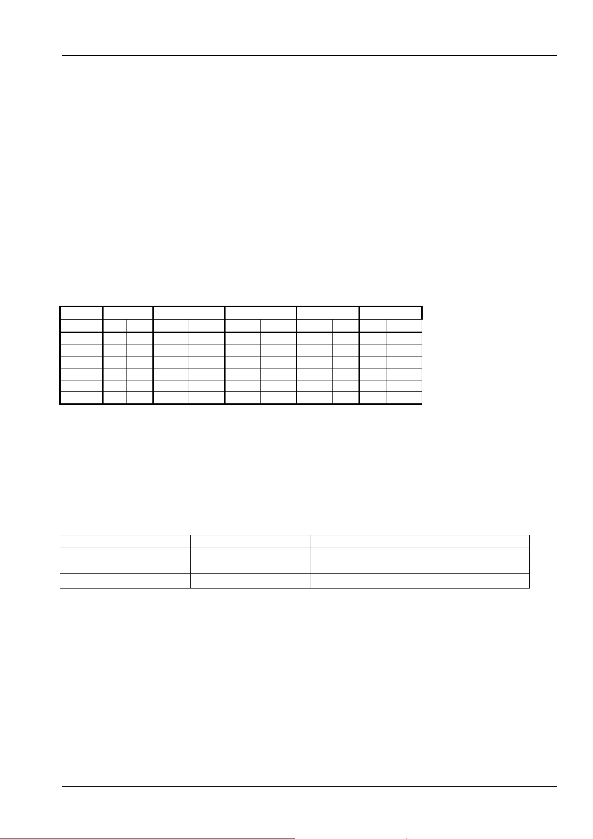
BENNING IT 115 Technical data
AC
7.3 Residual current protection devices (RCDs)
7.3.1 General data
Nominal tripping differential current ........10 mA, 30 mA, 100 mA, 300 mA, 500 mA, 1000 mA
Accuracy.................................................-0 / +0,1⋅I∆; I∆ = I∆N, 2×I∆N, 5×I∆N
-0.1⋅I∆ / +0; I∆ = 0.5×I∆N
AS / NZS: ± 5 %
Shape of testing current..........................sinusoidal (type AC), pulsating (type A, type F)
DC offset for pulsating testing current.....6 mA (typical)
RCD type................................................undelayed, delayed (S)
Initial polarity of the testing current ........ 0º or 180º
Voltage range .........................................93 V ÷ 134 V (45 Hz ÷ 65 Hz)
185 V ÷ 266 V (45 Hz ÷ 65 Hz)
Current selection for RCD testing (r.m.s. value calculated for 20 ms) according to IEC 61009:
I∆N × 1/2 I∆N × 1 I∆N × 2 I∆N × 5 RCD I∆
I∆N (mA)
10 5 3,5 10 20 20 40 50 100
30 15 10,5 30 42 60 84 150 212
100 50 35 100 141 200 282 500 707
300 150 105 300 424 600 848 1500 500 250 175 500 707 1000 1410 2500 -
1000 500 350 1000 1410 2000 - - -
„-„ ...........................................................not applicable
Type AC .................................................sinusoidal testing current
Type A, type F ........................................pulsating testing current
A, F AC A, F AC A, F AC A, F AC A, F
7.3.2 Contact voltage (Uc)
Measuring range according to EN 61557-6: 20.0 V ÷ 31.0 V for limiting value of 25 V
Measuring range according to EN 61557-6: 20.0 V ÷ 62.0 V for limiting value of 50 V
Measuring range (V) Resolution (V) Accuracy
0.0 ÷ 19.9
20.0 ÷ 99.9
0.1
0.1 (-0 % / +15 %) of the measured value
The specified accuracy shall apply for stable mains voltages and protective conductor connections
without any interference voltages.
Testing current....................................... max. 0.5×I∆N
Limiting value for contact voltage........... 25 V, 50 V
The specified accuracy shall apply to the entire measuring range.
(-0 % / +15 %) of the measured value
± 10 digits
- 55 -

BENNING IT 115 Technical data
7.3.3 Tripping time (RCD t)
The entire measuring range complies with the requirements specified in the EN 61557-6 standard.
Measuring range (ms) Resolution (ms) Accuracy
0.0 ÷ 40.0
0.0 ÷ max. time *
0.1
0.1
±1 ms
±3 ms
* The maximum measuring duration depends on the RCD testing standard selected (see chapter
4.4.5 RCD testing) – The specification shall apply to maximum times >40 ms.
Testing current....................................... ½×I∆N, I∆N, 2×I∆N, 5×I∆N
5×I∆N is not available for I∆N=1000 mA (RCD type AC) or I
≥ 300 mA (RCD type A, type F).
∆N
2×I∆N is not available for I∆N=1000 mA (RCD type A, type F).
The specified accuracy shall apply to the entire measuring range.
7.3.4 Tripping current (RCD I)
Tripping current
The entire measuring range complies with the requirements specified in the EN 61557-6 standard.
Accuracy
0.2×I
0.2×I
Measuring range I
0.2×I
∆N
∆N
÷ 1.1×I∆N (type AC) 0.05×I∆N ±0.1×I∆N
∆N
÷ 1.5×I∆N (type A, I∆N≥ 30 mA) 0.05×I∆N ±0.1×I∆N
÷ 2.2×I∆N (type A, I∆N≥ 30 mA) 0.05×I∆N ±0.1×I∆N
Resolution I
∆∆∆∆
∆∆∆∆
Tripping time
Measuring range (ms) Resolution (ms)
0 ÷ 300
1
Accuracy
±3 ms
Contact voltage
Measuring range (V) Resolution (V) Accuracy
0.0 ÷ 19.9
20.0 ÷ 99.9
0.1
0.1 (-0 % / +15 %) of the measured value
(-0 % / +15 %) of the measured value
± 10 digits
The specified accuracy shall apply for stable mains voltages and protective conductor connections
without any interference voltages.
The specified accuracy shall apply to the entire measuring range.
- 56 -

BENNING IT 115 Technical data
7.4 Loop impedance and prospective short-circuit current
7.4.1 Zs function (for systems without RCD)
Loop impedance
Measuring range according to EN 61557-3: 0.25 Ω ÷ 9.99 kΩ
Measuring range (ΩΩΩΩ) Resolution (ΩΩΩΩ)
0.00 ÷ 9.99
10.0 ÷ 99.9
100 ÷ 999
1.00 k ÷ 9.99 k
Prospective short-circuit current (calculated value)
Measuring range (A) Resolution (A) Accuracy
0.00 ÷ 9.99
10.0 ÷ 99.9
100 ÷ 999
1.00 k ÷ 9.99 k
10.0 k ÷ 23.0 k
The accuracy specified shall apply provided that the mains voltage is stable during measurement.
Testing current (at 230 V) ...................... 6.5 A (10 ms)
Nominal voltage range........................... 93 V ÷ 134 V (45 Hz ÷ 65 Hz)
185 V ÷ 266 V (45 Hz ÷ 65 Hz)
0.01
0.1
1
10
0.01
0.1
1
10
100
± (5 % of the measured value + 5 digits)
±10 % of the measured value
Please observe the accuracy of the loop
resistance measurement.
Accuracy
7.4.2 Zsrcd function (for systems with RCD)
Loop impedance
Measuring range according to EN 61557-3: 0.46 Ω ÷ 9.99 kΩ
Measuring range (ΩΩΩΩ) Resolution (ΩΩΩΩ)
0.00 ÷ 9.99
10.0 ÷ 99.9
100 ÷ 999
1.00 k ÷ 9.99 k
Accuracy might be impaired due to interference voltages in the mains voltage.
Prospective short-circuit current (calculated value)
Measuring range (A) Resolution (A) Accuracy
0.00 ÷ 9.99
10.0 ÷ 99.9
100 ÷ 999
1.00 k ÷ 9.99 k
10.0 k ÷ 23.0 k
Nominal voltage range........................... 93 V ÷ 134 V (45 Hz ÷ 65 Hz)
185 V ÷ 266 V (45 Hz ÷ 65 Hz)
No tripping of the residual current protection device (RCD).
0.01
0.1
1
10
0.01
0.1
1
10
100
±(5 % of the measured value + 10
±10 % of the measured value
Please observe the accuracy of the
loop impedance measurement.
Accuracy
digits)
- 57 -

BENNING IT 115 Technical data
7.5 Line impedance and prospective short-circuit current / voltage drop
Line impedance
Measuring range according to EN 61557-3: 0.25 Ω ÷ 9.99 kΩ
Measuring range (ΩΩΩΩ) Resolution (ΩΩΩΩ)
0.00 ÷ 9.99
10.0 ÷ 99.9
100 ÷ 999
1.00 k ÷ 9.99 k
0.01
0.1
1
10
± (5 % of the measured value + 5
±10 % of the measured value
Prospective short-circuit current (calculated value)
Measuring range (A) Resolution (A) Accuracy
0.00 ÷ 0.99
1.0 ÷ 99.9
100 ÷ 999
1.00 k ÷ 99.99 k
100 k ÷ 199 k
0.01
0.1
1
10
1000
Please observe the accuracy of the
line impedance measurement.
Testing current (at 230 V) ...................... 6.5 A (10 ms)
Nominal voltage range........................... 93 V ÷ 134 V (45 Hz ÷ 65 Hz)
185 V ÷ 266 V (45 Hz ÷ 65 Hz)
321 V ÷ 485 V (45 Hz ÷ 65 Hz)
Voltage drop (calculated value)
Measuring range (%) Resolution (%) Accuracy
0.0 ÷ 99.9
0.1
Please observe the accuracy of the line
impedance measurement*.
Z
measuring range ............................0.00 Ω ÷ 20.0 Ω
REF
* Please refer to chapter 5.6.2 Voltage drop for information on how to calculate the voltage drop.
Accuracy
digits)
7.6 Earthing resistance
Measuring range according to EN61557-5: 2,00 Ω÷ 1999 Ω
Measuring range (ΩΩΩΩ) Resolution (ΩΩΩΩ)
0.00 ÷ 19.99
20.0 ÷ 199.9
200 ÷ 9999
0.01
0.1
1
±(5 % of the measured value + 5 digits)
Maximum auxiliary earth electrode resistance RC...100×RE or 50 kΩ (the lower value shall apply)
Maximum probe resistance RP................................100×RE or 50 kΩ (the lower value shall apply)
Additional error at R
Cmax
or R
.............................±(10 % of the measured value + 10 digits)
Pmax
Additional error at interference voltage of 3 V (50 Hz) ±(5 % of the measured value + 10 digits)
Open-circuit voltage................................................< 30 VAC
Short-circuit current ................................................<30 mA
Frequency of testing voltage...................................125 Hz, sinusoidal
Interference voltage indicating threshold.................1 V (< 50 Ω, maximum)
Automatic measurement of auxiliary earth electrode resistance and probe resistance.
Automatic monitoring of interference voltage.
Accuracy
- 58 -

BENNING IT 115 Technical data
7.7 TRMS voltage, frequency and phase sequence
7.7.1 TRMS voltage (AC/DC)
Measuring range (V) Resolution (V) Accuracy
0 ÷ 550
Measuring method................................. true r.m.s. value (TRMS)
Frequency range ................................... 0 Hz, 14 Hz ÷ 500 Hz
1
± (2 % of the measured value + 2 digits)
7.7.2 Voltage of the connection monitor
Measuring range (V) Resolution (V) Accuracy
10 ÷ 550
1
±(2 % of the measured value + 2 digits)
7.7.3 Frequency
Measuring range (Hz) Resolution (Hz) Accuracy
0.00 ÷ 9.99
10.0 ÷ 499.9
Voltage range ........................................ 10 V ÷ 550 V
0.01
0.1
±(0.2 % of the measured value + 1 digit)
7.7.4 Phase sequence (rotary field)
Voltage range ........................................ 100 V
Frequency range ................................... 14 Hz ÷ 500 Hz
Result displayed ................................... 1.2.3 or 3.2.1
÷ 550 VAC
AC
- 59 -

BENNING IT 115 Technical data
7.8 General data
Power supply voltage............................. 9 VDC (6×1.5 V batteries or storage batteries, type AA)
Operation............................................... typically 20 h
Input voltage of charging jack ................ 12 V ± 10 %
Input current of charging jack................. max. 400 mA
Storage battery charging current ........... 250 mA (internally regulated)
Measuring category ............................... 1000 V CAT II to earth
600 V CAT III to earth
300 V CAT III to earth
Protection class .................................... double insulation
Contamination level ............................... 2
Protection category................................ IP 40
Display .................................................. matrix display with 128 x 64 pixels and background lighting
Dimensions (w × h × d) .......................... 23 cm × 10.3 cm × 11.5 cm
Weight .................................................. 1.3 kg, without batteries / storage batteries
Reference conditions:
Temperature range................................ +10 °C ÷ +30 °C
Air humidity range.................................. 40 % rel. Air humidity ÷ 70 % rel. air humidity
Operating conditions:
Temperature range................................ 0 °C ÷ +40 °C
Maximum relative air humidity ............... 95 % rel. air humidity (0 °C ÷ 40 °C), non-condensing
Storage conditions:
Temperature range................................ -10 °C ÷ +70 °C
Maximum relative air humidity ............... 90 % rel. air humidity (-10 °C ÷ +40 °C)
80 % rel. air humidity (40 °C ÷ 60 °C)
The specified accuracy shall apply to the first year of use under reference conditions. If not specified
otherwise for the respective measuring function, an additional error of max. + 1 % of the measured
value + 1 digit has to be considered for the use under operating conditions.
- 60 -

BENNING IT 115 Appendix A – Fuse table
Appendix A Fuse table – Prospective short-circuit current
Fuse, utilization category gL / gG
gG: general-purpose fuse for general applications, mainly for cable and line protection
gL: former VDE utilization category, replaced by gG
Nominal
current
(A)
2 32.5 22.3 18.7 15.9 9.1
4 65.6 46.4 38.8 31.9 18.7
6 102.8 70 56.5 46.4 26.7
10 165.8 115.3 96.5 80.7 46.4
16 206.9 150.8 126.1 107.4 66.3
20 276.8 204.2 170.8 145.5 86.7
25 361.3 257.5 215.4 180.2 109.3
35 618.1 453.2 374 308.7 169.5
50 919.2 640 545 464.2 266.9
63 1217.2 821.7 663.3 545 319.1
80 1567.2 1133.1 964.9 836.5 447.9
100 2075.3 1429 1195.4 1018 585.4
125 2826.3 2006 1708.3 1454.8 765.1
160 3538.2 2485.1 2042.1 1678.1 947.9
200 4555.5 3488.5 2970.8 2529.9 1354.5
250 6032.4 4399.6 3615.3 2918.2 1590.6
315 7766.8 6066.6 4985.1 4096.4 2272.9
400 10577.7 7929.1 6632.9 5450.5 2766.1
500 13619 10933.5 8825.4 7515.7 3952.7
630 19619.3 14037.4 11534.9 9310.9 4985.1
710 19712.3 17766.9 14341.3 11996.9 6423.2
800 25260.3 20059.8 16192.1 13545.1 7252.1
1000 34402.1 23555.5 19356.3 16192.1 9146.2
1250 45555.1 36152.6 29182.1 24411.6 13070.1
Disconnection time [s]
35m 0.1 0.2 0.4 5
Minimum prospective short-circuit current (A)
- 61 -

BENNING IT 115 Appendix A – Fuse table
Line safety switch, tripping characteristic B
Range of instantaneous tripping: 3 - 5 x IN
Nominal
current
(A)
6 30 30 30 30 30
10 50 50 50 50 50
13 65 65 65 65 65
15 75 75 75 75 75
16 80 80 80 80 80
20 100 100 100 100 100
25 125 125 125 125 125
32 160 160 160 160 160
40 200 200 200 200 200
50 250 250 250 250 250
63 315 315 315 315 315
Line safety switch, tripping characteristic C
Range of instantaneous tripping: 5 - 10 x IN
Nominal
current
(A)
0.5 5 5 5 5 2.7
1 10 10 10 10 5.4
1.6 16 16 16 16 8.6
2 20 20 20 20 10.8
4 40 40 40 40 21.6
6 60 60 60 60 32.4
10 100 100 100 100 54
13 130 130 130 130 70.2
15 150 150 150 150 83
16 160 160 160 160 86.4
20 200 200 200 200 108
25 250 250 250 250 135
32 320 320 320 320 172.8
40 400 400 400 400 216
50 500 500 500 500 270
63 630 630 630 630 340.2
Disconnection time [s]
35m 0.1 0.2 0.4 5
Minimum prospective short-circuit current (A)
Disconnection time [s]
35m 0.1 0.2 0.4 5
Minimum prospective short-circuit current (A)
- 62 -

BENNING IT 115 Appendix A – Fuse table
Line safety switch, tripping characteristic K
Range of instantaneous tripping: 8 - 14 x IN
Nominal
current
(A)
0.5 7.5 7.5 7.5 7.5
1 15 15 15 15
1.6 24 24 24 24
2 30 30 30 30
4 60 60 60 60
6 90 90 90 90
10 150 150 150 150
13 195 195 195 195
15 225 225 225 225
16 240 240 240 240
20 300 300 300 300
25 375 375 375 375
32 480 480 480 480
Line safety switch, tripping characteristic D
Range of instantaneous tripping: 10 - 20 x IN
Nominal
current
(A)
0.5 10 10 10 10 2.7
1 20 20 20 20 5.4
1.6 32 32 32 32 8.6
2 40 40 40 40 10.8
4 80 80 80 80 21.6
6 120 120 120 120 32.4
10 200 200 200 200 54
13 260 260 260 260 70.2
15 300 300 300 300 81
16 320 320 320 320 86.4
20 400 400 400 400 108
25 500 500 500 500 135
32 640 640 640 640 172.8
Disconnection time [s]
35m 0.1 0.2 0.4
Minimum prospective short-circuit current (A)
Disconnection time [s]
35m 0.1 0.2 0.4 5
Minimum prospective short-circuit current (A)
- 63 -

BENNING IT 115 Appendix B – Standard and optional accessories
Appendix B Standard and optional accessories for specific
measuring functions
The table below lists recommended standard and optional accessories required for specific
measurements. Please refer to chapter 3.5 for further information on standard and optional
accessories.
Measuring function Appropriate accessories (accessories with item no. are optional)
Insulating resistance
Low-impedance resistance
Continuity test
Line impedance
(voltage drop)
Loop impedance
RCD testing
Earthing resistance
Phase sequence
(rotary field)
Voltage, frequency
universal three-wire test cable
"Commander" test probe (switchable by means of
"TEST" key) (044155)
universal three-wire test cable
"Commander" test probe (switchable by means of
"TEST" key) (044155)
40 m measuring line BENNING TA 5 (044039)
universal three-wire test cable
test cable with shock-proof plug
"Commander" test plug for shock-proof socket
(switchable by means of "TEST" key) (044149)
"Commander" test probe (switchable by means of
"TEST" key) (044155)
universal three-wire test cable
test cable with shock-proof plug
"Commander" test plug for shock-proof socket
(switchable by means of "TEST" key) (044149)
universal three-wire test cable
earthing kit consisting of two earth rods, three test
cables (044113)
universal three-wire test cable
16 A CEE measuring adapter, 5-pin, for voltage / rotary
field measurement (044148)
universal three-wire test cable
"Commander" test probe (switchable by means of
"TEST" key) (044155)
test cable with shock-proof plug
"Commander" test plug for shock-proof socket
(switchable by means of "TEST" key) (044149)
- 64 -

BENNING IT 115 Appendix C – Commanders
Appendix C "Commander" test probe, "Commander" test plug
C.1 Safety warnings
Measuring categories of the optional "Commanders"
"Commander" test probe (switchable by means of "TEST" key)
Item no. 044115
without attachable protective cap, 18 mm tip: CAT II 1000 V to earth
with attachable protective cap, 4 mm tip: CAT II 1000 V / CAT III 600 V / CAT IV 300 V
to earth
"Commander" test plug for shock-proof socket (switchable by means of "TEST" key)
Item no.: 044149 .................. CAT II 300 V to earth
The measuring categories of the "Commanders" might be lower than the measuring
category of the installation tester.
If the phase voltage is detected at the protective conductor connection (PE),
immediately stop all measurements and make sure that the fault will be eliminated.
Before replacing the batteries / storage batteries or opening the battery compartment
cover, disconnect the "Commander" both from the installation tester and from the
installation.
For repairs or service, please contact your specialty retailer or the BENNING Service
Center.
C.2 Batteries
The optional "Commanders" can be operated with of two alkaline batteries or two
rechargeable NiMH batteries (storage batteries) of size AAA. The usual operating time is
approximately 40 hours and shall apply to a capacity of at least 850 mAh.
Notes:
If the "Commanders" are not used for a longer period of time, remove all batteries /
storage batteries from the battery compartment.
Use alkaline batteries or rechargeable NiMH batteries of size AAA only! When using
rechargeable storage batteries, it is recommended to observe a minimum capacity of
850 mAh.
Please make sure that the batteries / storage batteries are inserted with correct
polarity, because otherwise the "Commander" cannot be operated and the batteries /
storage batteries will discharge.
- 65 -

BENNING IT 115 Appendix C – Commanders
C.3 Description of the optional "Commanders"
Figure C.1: Front of "Commander" test probe (switchable by means of "TEST" key)
Figure C.2: Front of the optional "Commander" test plug for shock-proof socket
(switchable by means of "TEST" key) (044149)
Caption:
TEST
LED
2
LED
3
LEDs
4
Function selector keys
5
MEM
6
LCD illumination
7
Measuring point
8
illumination
Batteries / storage
9
batteries
Battery compartment
10
cover
Protective cap
11
Figure C.3: Rear of the "Commander" test probe
Start of measurement 1
PE contact electrode for protective conductor connection
Left status RGB LED
Right status RGB LED
LEDs of the measuring point illumination
BENNING IT 115: without function
BENNING IT 115: Selection of the measuring function
BENNING IT 115: without function
BENNING IT 115: Storage / recall of measuring results
Switches on / off the LCD illumination of the installation
tester
Switches on / off the measuring point illumination
Size AAA, alkaline batteries or NiMH storage batteries
Battery compartment cover
Detachable protective cap, CAT IV 300 V
- 66 -

BENNING IT 115 Appendix C – Commanders
C.4 LED indications of the optional "Commanders"
Both LEDs yellow Warning! Phase voltage at the PE connection of the
"Commander"! Only indicated, if the silver "TEST" key of
the "Commander" is touched for > 1 second!
Right LED red Measuring result outside the preset limiting values
Right LED green Measuring result inside the preset limiting values
Left LED is flashing blue "Commander" is monitoring the input voltage
Left LED orange Voltage between testing terminals is higher than 50 V
Both LEDs are flashing red Battery voltage of the "Commander" is low
Both LEDs red and
"Commander" switches off
How to test the protective conductor connection (PE)
Select the ZI (L-N/L) (English: Z
means of the function selector switch.
Connect the optional "Commander" test plug (044149) to the test object (see figure C.4).
Touch the silver contact electrode of the "TEST" key at the "Commander" for at least one
second.
If the phase voltage is detected at the PE connection of the "Commander", the LEDs of the
Battery voltage too low to operate the "Commander"
), ZS (L-PE) (English: Z
LINE
) or FI/RCD function by
LOOP
"Commander" will light yellow. In addition, the warning is shown on the LC display of
the installation tester and the buzzer sounds. Further measurements must be stopped
immediately!
Figure C.4: Reversed L and PE conductors – Phase voltage at the PE connection is
detected by touching the "TEST" key of the optional "Commander" test plug (044149).
- 67 -
 Loading...