

D
Bedienungsanleitung
Operating manual
F
Mode d‘emploi
E
Manuel de instrucciones
Návod k použití zkoušečky
Brugsanvisning
Käyttöohje
Οδηγίες χρήσεως
I
Istruzioni per l’uso
N
Bruksanvisning
Gebruiksaanwijzing
P
Manual de instrucões
Instrukcja obsługi
S
Bruksanvisning
Dutest aletinin kullanma
tarifnamesi
®
T.-Nr. 785857.02/ 12-2005
DUTEST
geprüft und zugelassen
BENNING Elektrotechnik & Elektronik GmbH & Co.KG
Münsterstraße 135 - 137 • D - 46397 Bocholt
Telefon ++49 (0) 2871 - 93 - 0 • Fax ++49 (0) 2871 - 93 - 429
www.benning.de • E-Mail: duspol@benning.de
D
Bedienungsanleitung
DUTEST
Bevor Sie den Durchgangs- und Leitungsprüfer
®
benutzen: Lesen Sie bitte die Bedie-
DUTEST
nungsanleitung und beachten Sie unbedingt die
Sicherheitshinweise!
Inhaltsverzeichnis:
1. Sicherheitshinweise
2. Funktionsbeschreibung
3. Funktionsprüfung/ Inbetriebnahme
4. So prüfen Sie eine elektrisch leitende Verbindung (Durchgangsprüfung)
4.1 So prüfen Sie die Durchgangs- und Sperrichtung von Halbleitern
5. Taschenlampenfunktion
6. Lampenwechsel
7. Technische Daten
8. Allgemeine Wartung
9. Umweltschutz
1. Sicherheitshinweise
Auf dem Gerät sind internationale elektrische Symbole
mit folgender Bedeutung abgebildet:
Achtung, Dokumentation beachten!
Gleich- oder Wechselstrom (DC/ AC).
Durchgängige doppelte oder verstärkte Isolierun-
gen (Schutzklasse II, IEC 60536).
- Dieses Gerät ist gemäß DIN VDE 0403/
DIN VDE 0411- / EN 61010 Teil 1 gebaut und
geprüft und hat das Werk in sicherheitstechnisch
einwandfreiem Zustand verlassen. Um diesen Zustand zu erhalten und einen gefahrlosen Betrieb
sicherzustellen, sind die Hinweise und Warnvermerke zu beachten, die in dieser Bedienungsan
leitung enthalten sind.
- Dieses Gerät ist für die Benutzung nach
IEC 60664, Kategorie II vorgesehen. Es ist für die
Verwendung in Schaltkreisen bis 400 V geeignet.
- Das Gerät darf nur zum Prüfen des Durchgangs
von elektrischen Verdrahtungen, Leitungsnetzen, Anlagen, Geräten, Bauteilen bis zu einer
Nennspannung von 400 V
tätsermittlung von Halbleitern benutzt werden.
Max. Spannung gegen Erde 300 V !
- Gerät beim Prüfen nur an den isolierten Prüfgriffen
anfassen und die Prüfelektroden (Prüf-
spitzen) nicht berühren!
- Eine Durchgangs- und Halbleiterprüfung ist nur
zulässig, wenn das zu prüfende Anlagenteil spannungsfrei geschaltet ist.
- Vor dem Öffnen des Batteriedeckels
Prüfgriffe von allen Spannungsquellen und Messkreisen zu trennen.
Der Deckel des Batteriefaches, an der Unterseite
des Gerätes, lässt sich z. B. durch einen 5,5 mm
Schraubendreher öffnen. Hierzu Schraubendreher in die Schlitze an der Schmalseite einführen
und durch eine leichte Drehbewegung den Deckel
abhebeln. Batterien immer polrichtig einlegen!
Falls das Gerät längere Zeit nicht gebraucht wird,
Batterien aus dem Gerät entfernen!
Verbrauchte Batterien nicht wegwerfen, als Son-
dermüll entsorgen!
- Beachten Sie, Arbeiten an spannungsführenden
Teilen und Anlagen sind grundsätzlich gefährlich.
Bereits Spannungen ab 30 V AC und 60 V DC
können für den Menschen lebensgefährlich sein.
-
Vermeiden Sie unbedingt ein Feucht- oder Nasswerden des Messgerätes. Ebenso ist das Gerät vor
Verunreinigungen und Beschädigungen zu schützen!
- Vermeiden Sie eine Betauung des Gerätes (Kondenswasserbildung). Diese tritt ein, wenn das
Gerät aus einer kalten in eine warme Umge
bung gebracht wird. Im Innern des Gerätes wird
dadurch die Isolationsfestigkeit herabgesetzt und
es können Messfehler auftreten. In diesem Fall
das Gerät ca. 1 Stunde bei höherer Temperatur an
geeigneter Stelle aufbewahren.
- Wenn anzunehmen ist, dass ein gefahrloser
Betrieb nicht mehr möglich ist, so ist das Gerät
außer Betrieb zu setzen und gegen unabsichtlichen Betrieb zu sichern.
Es ist anzunehmen, dass ein gefahrloser Betrieb
nicht mehr möglich ist,
- wenn das Gerät sichtbare Beschädigungen
aufweist (Gehäuse, Kabel, Prüfgriffe),
®
sowie zur Polari-
sind die
- wenn die Funktion einer oder mehrerer Anzeigen ausfällt oder keine Funktionsbereitschaft
zu erkennen ist,
- nach längerer Lagerung unter ungünstigen
Verhältnissen,
- nach schweren Transportbeanspruchungen.
- Zum Reinigen des Gerätes verwenden Sie ein mit
mildem Spülmittel angefeuchtetes Tuch. Falls Batterie-Elektrolyt ausgelaufen ist, Batteriefach und
Kontakte sorgfältig säubern!
Achtung:
Unmittelbar vor dem Benutzen des Gerätes ist unbedingt die Spannungsfreiheit des Anlagenteiles festzustellen! Verwenden Sie hierfür z. B. einen zweipoligen
Spannungsprüfer.
2. Funktionsbeschreibung
Der DUTEST® ist ein Durchgangs- und Leitungsprüfer
nach VDE 0403, mit optischer und akustischer Prüf
anzeige. Das Gerät ist zur Durchgangsprüfung von
elektrischen Verdrahtungen, Leitungsnetzen, Anlagen,
Geräten und Bauteilen bis zu einem Messwiderstandswert von 90 k
die Polarität an Halbleiterbauelementen wie Dioden,
Transistoren usw. ermittelt werden.
Für den Betrieb werden 3 Mignon-Batterien 1,5 V (IEC/
DIN R6/ LR6) benötigt.
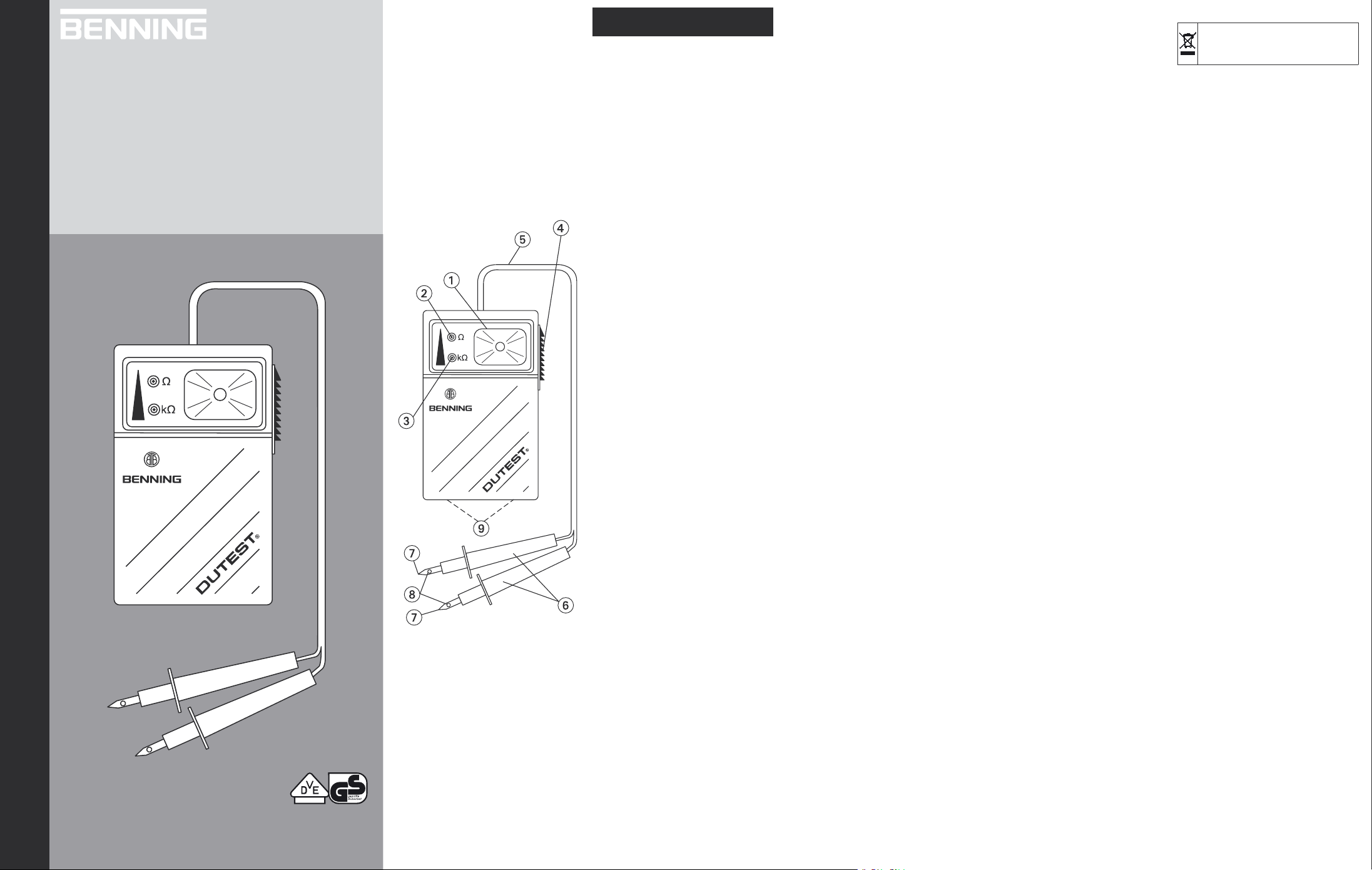
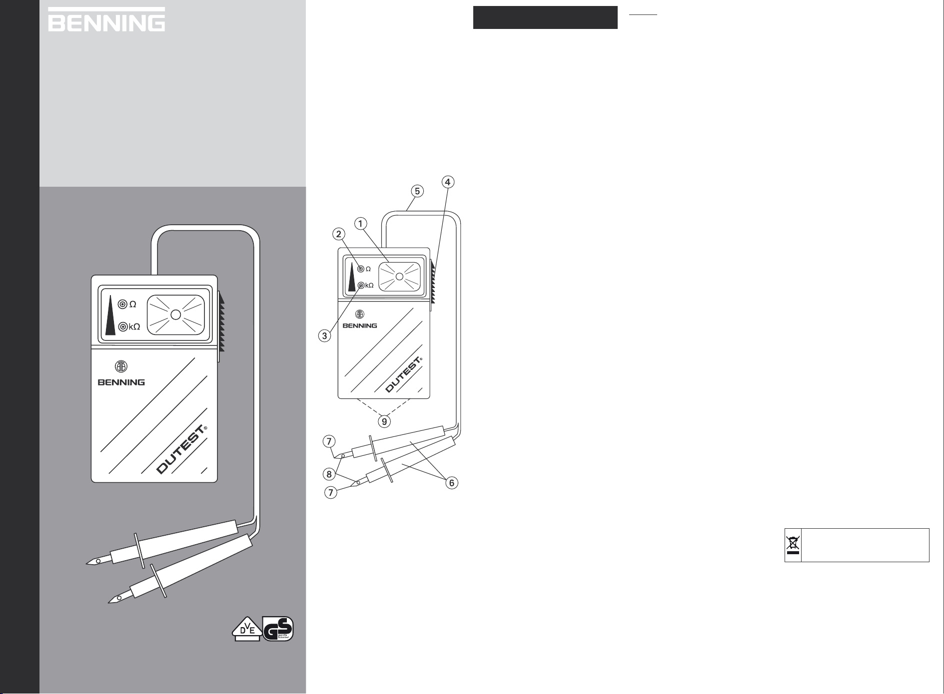
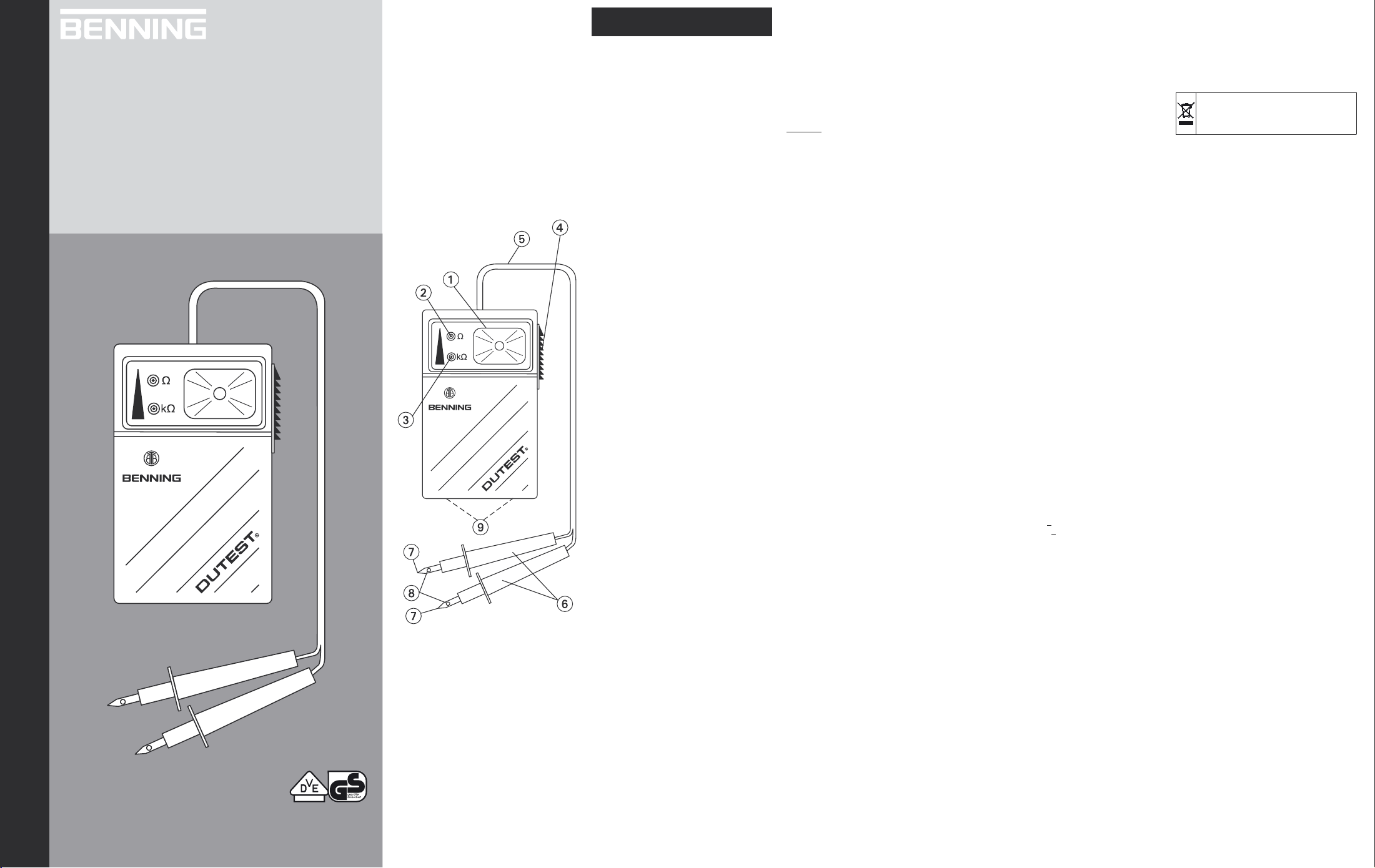
Das Gerät verfügt über eine optische Anzeige mit 2
Leuchtdioden (LED)
Anzeige mittels Prüfsummer.
Am Gerät befinden sich zwei fest angeschlossene Prüfleitungen
Jeder Prüfgriff hat eine blanke Prüfelektrode (Prüfspitze) mit einer Bohrung zur Aufnahme von Einzeladern bis 2,5 mm² Leitungsquerschnitt .
Auf die Prüfelektroden (Prüfspitzen)
verschiedenartige Abgreifklemmen setzen. Der Durchmesser der Prüfelektrode beträgt 4 mm. Über einen
Schalter lässt sich das Gerät als Taschenlampe
betreiben.
Die optische und akustische Anzeige
Im Anzeigefeld befinden sich rechts ein Lampenreflektor mit Glühlampe und links zwei kreisförmige
-
Lichtlinsen mit Leuchtdioden (LED)
LED-Anzeigen sind mit den Symbolen
gekennzeichnet und signalisieren den jeweiligen Prüfbereich. Ein im Gerät integrierter Prüfsummer dient
der akustischen Anzeige.
3. Funktionsprüfung/ Inbetriebnahme
- Das Gerät darf nur zum Prüfen des Durchgangs
- Vor der Inbetriebnahme des Gerätes sind 3 Mig-
- Auf ein polrichtiges Einsetzen der 3 Mignon-Bat-
- Überprüfen Sie durch Kontaktierung der beiden
- Verwenden Sie den Durchgangsprüfer nicht,
4. So prüfen Sie eine elektrisch leitende Verbin-
- Die Durchgangsprüfung ist an spannungsfrei
- Die benötigte Prüfspannung liefern die im Gerät
- Eine Prüfung ist im Bereich von 0 - 90 k mög-
- Legen Sie die Prüfgriffe
-
- Bei Kontaktierung der Prüfelektroden
Zur einfachen Kontaktierung von Leitungen kann
hilfsweise die Bohrung
geeignet zur Aufnahme von Einzeladern bis 2,5 mm²
Leitungsquerschnitt.
ausgelegt. Mit dem Gerät kann auch
und sowie eine akustische
mit einem roten und schwarzen Prüfgriff .
lassen sich
und . Die
””
von spannungsfrei geschalteten elektrischen Verdrahtungen, Leitungsnetzen, Anlagen, Geräten
und Bauteilen sowie zur Polaritätsermittlung bei
Halbleiter-Bauelementen benutzt werden!
non-Batterien 1,5 V (IEC/ DIN R6/ LR6) im Batteriefach einzusetzen. Das Batteriefach befindet
sich hinter dem Gehäusedeckel auf der Rückseite
des Gerätes. Der Gehäusedeckel hat an beiden
Gehäuseseiten zwei Öffnungsschlitze und ist mit
einem Werkzeug, z. B. Schraubendreher zu öff
nen.
terien ist zu achten!
Prüfelektroden
gung des Prüfgerätes und damit die Funktionen
der LED-Anzeigen und des Prüfsummers.
wenn nicht alle Anzeigeelemente einwandfrei funktionieren!
dung (Durchgangsprüfung)
geschalteten Anlagenteilen durchzuführen, ggfs.
sind Kondensatoren zu entladen.
integrierten 3 Mignon-Batterien 1,5 V.
lich.
an die zu prüfenden Anlagenteile.
elektrisch leitende Verbindung leuchtet bei einem
Messwiderstandswert < 900
auf und der Prüfsummer ertönt. Bei einem Messwiderstand > 900
und der Prüfsummer ertönt.
die interne Spannungsversor-
mit den Prüfelektroden
die LED und
leuchtet nur die LED auf
verwendet werden. Sie ist
und
”k”
an eine
4.1 So prüfen Sie die Durchgangs- und Sperrichtung von Halbleitern
- Die polaritätsabhängige Prüfung ist an spannungsfrei geschalteten Anlagenteilen durchzuführen.
- Die benötigte Prüfspannung liefern die im Gerät
integrierten 3 Mignon-Batterien 1,5 V.
Der rote Prüfgriff
Der schwarze Prüfgriff
- Eine Prüfung ist im Bereich von 0 - 90 k
lich.
- Legen Sie die Prüfgriffe
an die zu prüfenden Anlagenteile.
- Bei Kontaktierung der Prüfelektroden an einen
Halbleiter leuchten bei Durchgang und bei einem
Messwiderstand < 900
der Prüfsummer ertönt. Bei einem Messwiderstand
> 900
auf und der Prüfsummer ertönt. Bei Über-
LED
-
schreitung des Widerstandswertes von 90 k
tet keine LED und der Prüfsummer ertönt ebenfalls
nicht. Bei Sperrichtung erfolgt keine Anzeige!
Zur einfachen Kontaktierung von Leitungen kann
hilfsweise die Bohrung
geeignet zur Aufnahme von Einzeladern bis 2,5 mm²
Leitungsquerschnitt.
5. Taschenlampenfunktion
Durch den seitlich im Gerät integrierten Schalter
kann Dauerlicht eingeschaltet werden. Unabhängig
von der Schalterstellung ist die Funktionsbereitschaft
zur Durchgangsprüfung und die zur Polaritätsermittlung von Halbleitern gegeben.
6. Lampenwechsel
Achtung, beim Einbau der Lampe (Glühbirne) diese so
in die Fassung stecken, dass der seitliche Lötnippel in
der breiten Aussparung der Fassung liegt (bei Nichtbe
achtung Klemmprobleme beim Herausnehmen)!
Hinweis:
Beim Öffnen des Gehäuses (Batteriewechsel) kann die
Linsenlampe herausfallen, bringen Sie den Schalter in
Ein-Stellung, so wird die Linsenlampe festgeklemmt.
7. Technische Daten
- Nennspannungsbereich: max. 400 V
Spannung gegen Erde 300 V
Überspannungskategorie: II (IEC 60664)
-
(Das Gerät ist gegen Überspannungsspitzen
2500 V geschützt.)
- Verschmutzungsgrad: 2 (IEC 60664)
-
Innenwiderstand: ca. 82 k
Leerlaufspannung: ≤ 5 V
-
Prüfstrom: ≤ 60 µA
-
Nennfrequenzbereich: 0 bis 60 Hz
-
Funkstörgrad: B
-
Umgebungsbedingungen:
-
Höhe: bis 2000 m NN
Temperaturbereich:
- 10 °C bis 50 °C (Arbeitstemperaturbereich)
- 20 °C bis 65 °C (Lagertemperaturbereich)
max. rel. Feuchte: 80 % bis 31 °C,
-
linear abnehmend
40 % bis 50 °C
-
Schutzklasse: II (IEC 60536)
- Schutzart: IP 30
3 - erste Kennziffer: Schutz gegen Zugang zu gefähr-
lichen Teilen und Schutz gegen feste Fremdkörper,
> 2,5 mm Durchmesser
0 - zweite Kennziffer: Kein Wasserschutz
- Abmessung: L 97 x B 59 x H 30 mm (ohne Kabel
und Prüfgriffe)
- Lampenbestückung:
- Gewicht: 130 g
Batteriebestückung: 3 Mignon-Batterien 1,5 V
-
(IEC/ DIN R6/ LR6)
- Verbindungskabel mit Prüfgriffen: 1000 mm lang
8. Allgemeine Wartung
Reinigen Sie das Gehäuse äußerlich mit einem saube
ren trockenen Tuch (Ausnahme spezielle Reinigungs
tücher). Verwenden Sie keine Lösungs- und/ oder
Scheuermittel, um den Durchgangs- und Leitungsprü
fer zu reinigen. Achten Sie unbedingt darauf, dass das
Batteriefach und die Batteriekontakte nicht durch aus
laufendes Batterie-Elektrolyt verunreinigt werden.
Falls Elektrolytverunreinigungen oder weiße Ablage
rungen im Bereich der Batterie oder des Batteriege
häuses vorhanden sind, reinigen Sie auch diese mit
einem trockenen Tuch.
Batterie-Entsorgung:
Batterien gehören nicht in den Hausmüll. Als Verbrau
cher sind Sie gesetzlich verpflichtet, gebrauchte Bat
terien zurückzugeben. Sie können Ihre alten Batterien
bei den öffentlichen Sammelstellen in Ihrer Gemeinde
oder überall dort abgeben, wo Batterien der betreffenden Art verkauft werden. Vermeiden Sie die Verwen
dung schadstoffhaltiger Batterien!
ist der ‘Pluspol’.
ist der ‘Minuspol’.
mit den Prüfelektroden
die LED und auf und
bis 90 k leuchtet bei Durchgang nur die
verwendet werden. Sie ist
max.
(DIN 40050)
Linsenlampe E 10 3,7 V 0,3 A
mög-
leuch-
bis
9. Umweltschutz
-
-
-
-
-
-
-
-
-
-
Bitte führen Sie das Gerät am Ende seiner
Lebensdauer den zur Verfügung stehenden
Rückgabe- und Sammelsystemen zu.
D
Bedienungsanleitung
Operating manual
F
Mode d‘emploi
E
Manuel de instrucciones
Návod k použití zkoušečky
Brugsanvisning
Käyttöohje
Οδηγίες χρήσεως
I
Istruzioni per l’uso
N
Bruksanvisning
Gebruiksaanwijzing
P
Manual de instrucões
Instrukcja obsługi
S
Bruksanvisning
Dutest aletinin kullanma
tarifnamesi
®
T.-Nr. 785857.02/ 12-2005
DUTEST
geprüft und zugelassen
BENNING Elektrotechnik & Elektronik GmbH & Co.KG
Münsterstraße 135 - 137 • D - 46397 Bocholt
Telefon ++49 (0) 2871 - 93 - 0 • Fax ++49 (0) 2871 - 93 - 429
www.benning.de • E-Mail: duspol@benning.de
Instruction manual
DUTEST
Before you use the continuity and circuit tester
DUTEST®: Please read the instruction manual and
make sure that you follow the safety instructions!
Index of contents:
1. Safety instructions
2. Mode of operation
3. Operating check/ commissioning
4. How to test an electrically conductive circuit
(continuity test)
4.1 How to test the continuity and reverse direc
tion of semiconductors
5. Pocket torch function
6. Lamp replacement
7. Technical data
8. General maintenance
9. Environmental notice
1. Safety instructions
On the unit there are shown international electrical
symbols with the following meanings:
Attention, read documentation!
Direct- or alternative current (DC/ AC).
Continuous double or strengthened isolation
(protection
- This unit is built and tested in accordance with DIN
VDE 0403/ DIN VDE 0411- / EN 61010 part 1 and
supplied in a sound condition. In order to maintain
this condition and to ensure a safe operation, the
user has to follow the instructions and warnings
which are included in this instruction manual.
- This unit is provided for the use in accordance
with IEC 60664, category II. It is suitable for the
use in circuits up to 400 V .
- The unit must only be used for the continuity
testing of electrical wiring, networks, systems,
equipment, components up to a nominal voltage
of 400 V
semiconductors.
Max voltage from earth 300 V
- Handle the instrument only by the insulated grips
and do not touch the test probes !
- A continuity and semiconductor test must not be
performed on live equipment.
- Before opening the battery cover , the test grips
must be disconnected from all voltage sources
and measuring circuits.
The battery compartment cover underneath the
unit can be opened (by a 5,5 mm screwdriver).
To do this put the screwdriver in the slot at the
small side and remove the cover by a slight rotary
motion. Always insert the batteries with the correct
poles!
If the unit is not used for a long time, remove the
batteries from the unit!
Do not throw away used batteries, dispose these
as toxic waste!
- Please note that working on live circuits and
systems is always dangerous. Voltages from 30 V
AC and 60 V DC can be extremely dangerous to
the human body.
- Avoid getting the instrument wet or moist. It is also
important to keep the continuity tester
clean!
- Avoid the development of water condensation.
This occurs if the unit is brought from the cold
into a warm environment. This can cause the insulating strength to be reduced inside the unit and
errors in measurement can arise. If this happens,
the unit has to be kept for approx. 1 hour at a higher temperature in a suitable place.
- If it is assumed that safe operation is no longer
possible, the unit has to be switched off and secured against unintentional use.
It has to be assumed that a safe operation is no
longer possible,
- if the unit shows visible damages (housing,
- if the function of one or several displays fails
- after long storage in unfavourable conditions,
- after stress due to transportation.
- For cleaning the unit use a cloth moistened with a
small amount of washing-up liquid. If battery electrolyte has run out, thoroughly clean battery com
partment and contacts!
II, IEC 60536).
and for the polarity determination of
cable, test grips),
or the unit fails to function correctly,
®
!
Attention:
Immediately before use, ensure that the equipment is
not live! Please use a two-pole voltage tester for this
check, not the Dutest.
2. Mode of operation
The Dutest is a continuity and circuit tester in
accordance with VDE 0403, with visual and acoustic
test indication. The unit is designed for continuity testing of electrical wiring, networks, systems, equipment
and components up to a measuring resistor value of
90 k
. With this unit the polarity of semiconductor
components such as diodes, transistors, etc. can be
determined.
For operation 3 Mignon-batteries 1,5 V (IEC/ DIN R6/
LR6) are needed.
The unit has a visual indication with two LEDs
-
and an acoustic indication by means of a test buzzer.
The unit has two test leads attached.
Each test grips
(test probe)
wires up to 2,5 mm² .
Different crocodile clips can be used on the test electrodes (test probes)
trodes is 4 mm. Via a switch
operated as pocket torch.
Visual and acoustic indication
In the display window there is a torch reflector with a
bulb on the right and two circular light lenses with
LEDs and on the left. The LED indications are
marked with the symbols
respective testing range. A test buzzer, which is inte
grated in the unit, serves for the acoustic indication.
3. Operating check/
- The unit may be only used for continuity testing
of dead electrical wiring, networks, systems, equipment and components as well as for polarity determination of semiconductor components!
- Before the commissioning of the unit, 3 Mignon-
batteries 1,5 V (IEC/ DIN R6/ LR6) have to be put
into the battery compartment. The battery compartment is behind the housing cover at the rear of
the unit. The housing cover has an opening slot at
both housing sides of the unit and can be opened
with a tool e. g. screwdriver.
- When putting in the 3 Mignon-batteries, pay atten-
tion to the correct polarity!
- Check the internal voltage supply of the tester and
with it the function of the LED-indications and the
test buzzer by touching together the two test electrodes .
- Do not use the continuity tester unless all func-
tions are operating correctly!
4. How to test the continuity and reverse
direction of semicondutors (continuity test)
- The continuity test must not be performed on live
equipment, if necessary, capacitors have to be
discharged.
- The necessary test potential is provided by the 3
Mignon-batteries 1,5 V, which are integral in the
unit.
- Testing is possible in the range from 0 - 90 k
- Connect the test grips
to the equipment to be tested.
- By contacting the test electrodes
cally conductive circuit, the LEDs
up and the test buzzer sounds in case of a measuring resistor < 900
resistor > 900
test buzzer sounds.
For easy connecting the hole
used. It is suitable for the connection of single wires
up to 2,5 mm².
4.1 How to test the continuity and reverse direc-
tion of semiconductors
- The polarity-dependent test must not be performed
on live equipment.
- The necessary test potential is provided by the 3
Mignon-batteries 1,5 V, which are integrated in the
unit.
The red test grip
The black test grip
- Testing is possible in the range from 0 - 90 k
- Connect test grips
equipment to be tested.
- By contacting the test electrodes
ductor, the LEDs
buzzer sounds if the circuit is made and in case
of a measuring resistor < 900
measuring resistor > 900
lights up and the test buzzer sounds if the cir-
-
cuit is made. In case of reverse direction no indica-
tion is made!
has an uninsulated test electrode
with a hole for the connection of single
. The diameter of the test elec-
the unit can also be
””
and
”k”
and signal the
commissioning
with test electrodes
to an electri-
and light
. In case of a measuring
, only the LED lights up and the
can additionally be
is the ‘positive pole’.
is the ‘negative pole’.
with test electrodes to the
and light up and the test
to a semicon-
. In case of a
to 90 k, only the LED
For easy connecting the hole can additionally be
used up to 2,5 mm².
5. Pocket torch function
By the switch at the side of the unit it can be switched to ‘permanently ON’ position. The possibility of
continuity testing and polarity determination of semiconductors is given independently of the switch position.
6. Lamp replacement
Attention! When installing the lamp (bulb), put it into
socket ensuring that the soldered fitting at its side is
placed in the large recess of the socket (otherwise, the
lamp might be jammed when removing it)!
Note:
and
When opening the housing (battery replacement), the
lens tip lamp might drop out of the housing. Set the
switch to the ON position in order to clamp the lens
tip lamp.
7. Technical data
- Nominal voltage range: max. 400 V
max. voltage from earth 300 V
- Overvoltage category: II (IEC 60664)
(The unit is protected against an overvoltage
surge up to 2500 V.)
- Pollution degree: 2 (IEC 60664)
- Internal resistance: approx. 82 k
- No-load voltage:
- Test current:
- Nominal frequency range: 0 to 60 Hz
- Radio interference suppression: B
-
- Environmental conditions:
Height: up to 2000 m above sea level
Temperature range:
- 10 °C to 50 °C (operating temperature range)
- 20 °C to 65 °C (storing temperature range)
Max. rel. humidity: 80 % up to 31 °C linearly
decreasing 40 % up to 50 °C
- Protection class: II (IEC
- Protection: IP 30 (DIN 40050)
IP 30 means: Protection against access to dange
rous parts and protection against solid impurities
of a diameter > 2.5 mm, (3 - first index). No protection against water, (0 - second index).
- Dimensions: L 97 x B 59 x H 30 mm
(without cable and test grips)
- lamp type:
- Weight: 130 g
- Battery: 3 Mignon-batteries 1,5 V
(IEC/ DIN R6/ LR6)
- Connecting cable with test grips: 1000 mm long
8. General maintenance
Clean the exterior of the housing with a clean dry
cloth (exception: special cleansing cloths). Do not
use solvents and/ or abrasives to clean the continuity
and circuit tester. Make sure not to contaminate the
battery compartment and the battery contacts with
leaking battery electrolyte. Should such electrolyte
contamination or white deposits occur near the battery
or the battery housing, these must also be removed
with a dry cloth.
.
Battery disposal:
Do not dispose of batteries with the household
garbage. You as a consumer are legally obliged to
return used batteries. You can return used batteries
to public collection facilities in your community area
or return them to any retail outlet selling similar
batteries. Avoid using batteries containing dangerous
substances!
9. Environmental notice
At the end of the product’s useful life, please
dispose of it at appropriate collection points
provided in your country.
.
5 V
60 µA
60536)
lens tip lamp E 10 3,7 V 0,3 A
-
D
Bedienungsanleitung
Operating manual
F
Mode d‘emploi
E
Manuel de instrucciones
Návod k použití zkoušečky
Brugsanvisning
Käyttöohje
Οδηγίες χρήσεως
I
Istruzioni per l’uso
N
Bruksanvisning
Gebruiksaanwijzing
P
Manual de instrucões
Instrukcja obsługi
S
Bruksanvisning
Dutest aletinin kullanma
tarifnamesi
®
T.-Nr. 785857.02/ 12-2005
DUTEST
geprüft und zugelassen
BENNING Elektrotechnik & Elektronik GmbH & Co.KG
Münsterstraße 135 - 137 • D - 46397 Bocholt
Telefon ++49 (0) 2871 - 93 - 0 • Fax ++49 (0) 2871 - 93 - 429
www.benning.de • E-Mail: duspol@benning.de
F
Notice d’utilisation
DUTEST®
Avant d’utiliser le contrôleur de continuité et de
circuit DUTEST
et assurez-vous que vous respectez les consignes
de sécurité!
Table des matières:
1. Consignes de sécurité
2. Mode d’opération
3. Vérification de fonctionnement/ mise en service
4. Comment contrôler une liaison électrique
conductrice (contrôle de continuité)
4.1 Comment contrôler le sens de continuité et de
non-conduction de semiconduc-teurs
5. Fonctionnement comme lampe de poche
6. Remplacement de la lampe
7. Fiche technique
8. Entretien général
9. Information sur l’environnement
1. Consignes de sécurité
Sur l’appareil, figurent les symboles internationaux
électriques suivants:
Attention, lire documentation!
Courant continu ou courant alternatif (DC/AC).
Isolation générale double ou renforcée (protection
II, IEC 60536).
- Cet appareil a été conçu et contrôlé conformément à la norme DIN VDE 0403 / DIN VDE 0411
- / EN 61010 Partie 1, et a quitté l’usine en parfaite
condition de sécurité technique. Pour le conserver
dans cet état et garantir un fonctionnement sans
danger, il faut observer les instructions et avertis
sements contenus dans cette notice d’utilisation.
- Cet appareil a été conçu pour une utilisation
conformément à la norme IEC 60664, Catégorie
II. Il convient pour un emploi dans les circuits de
commutation jusqu’à 400 V
- Utiliser cet appareil uniquement pour contrôler la
continuité de câblages, de réseaux, d’installations,
d’appareils et de composants électriques dont la
tension nominale maximum est de 400 V
que pour déterminer la polarité de semi-conduc
teurs.
Tension max. par rapport à la terre 300 V
- Lors du contrôle, saisir le contrôleur uniquement
par les poignées d’essai
tes d’essai !
- Le contrôle de continuité et de semi-conducteurs
est autorisé uniquement si les éléments à contrôler sont hors tension.
- Avant d’ouvrir le couvercle du logement des piles
, il faut séparer les poignées d’essai de toutes
les sources de tension et de tous les circuits de
mesure.
On peut démonter le couvercle du logement des
piles, se trouvant sur la partie inférieure de l’appareil, par ex. avec un tournevis de 5,5 mm. Pour
cela mettre le tournevis dans la fente du côté étroit
et enlever le couvercle par un léger mouvement
rotatif!
Veiller à respecter la polarité des piles!
Si l’appareil n’est pas utilisé longtemps, retirer les
batteries de l’appareil!
Ne pas jeter les batteries usagées, les traiter
comme déchets toxiques!
- Très important: les travaux effectués au niveau
des parties et installations sous tension sont toujours dangereux. Des tensions de 30 V AC et 60 V
DC peuvent déjà être mortelles pour l’homme.
- L’appareil doit toujours être à l’abri de l’humidité et
de la pluie. Il faut aussi protéger l’appareil contre
toute salissure et toute détérioration!
- Eviter toute formation d’eau de condensation
dans l’appareil. Ceci se produit quand on transporte un appareil d’un environnement froid dans
un environnement chaud. L’isolement à l’intérieur
de l’appareil baisse alors, pouvant entraîner des
erreurs de mesure. Dans ce cas, il faut laisser
l’appareil pendant env. 1 heure à un endroit approprié et à une température plus élevée.
- Si l’on considère qu’il n’est plus possible d’utiliser l’appareil sans danger, il faudra mettre celuici hors circuit et le protéger contre toute mise en
marche inopinée.
Un fonctionnement dangereux de l’appareil est
vraisemblable dans les cas suivants:
®
: Veuillez lire la notice d’utilisation
.
ainsi
!
sans toucher aux poin-
- lorsque l’appareil est visiblement endommagé
(boîtier, câble, poignées d’essai),
- lorsque la fonction d’un ou de plusieurs affichages fait défaut ou lorsque l’appareil ne
fonctionne pas correctement,
- après une longue durée de stockage dans
des conditions défavorables,
- à la suite d’un transport effectué dans de
mauvaises conditions.
- Pour nettoyer l’appareil, utiliser uniquement un
chiffon humidifié avec un détergent doux. Si l’électrolyte des piles a coulé, nettoyer soigneusement
le logement des piles et les contacts!
Attention:
Il faut absolument s’assurer que l’élément à contrôler
soit hors tension avant d’employer l’appareil! Pour
cela, utiliser, par ex. un contrôleur de tension bipolaire.
2. Mode d’opération
Le Dutest est un contrôleur de continuité et de cir
cuit selon la norme VDE 0403 et qui est doté d’un
affichage de contrôle optique et acoustique. Il est
conçu pour contrôler la continuité de câblages, de
réseaux, d’installations, d’appareils et de composants
électriques dont la valeur de résistance de mesure
maximum est de 90 k. Cet appareil permet également de déterminer la polarité de composants semiconducteurs comme des diodes, des transistors, etc.
Trois piles rondes de 1,5 V (IEC/DIN R6/LR6) sont
nécessaires pour le fonctionnement de l’appareil.
L’appareil est doté d’un affichage optique à deux
diodes électroluminescentes (LED)
d’un affichage acoustique à ronfleur.
Il dispose de deux circuits de contrôle
fixement et équipés d’une poignée d’essai rouge et
d’une poignée d’essai noire .
Chaque poignée
(pointe d’essai)
des conducteurs indépendants d’une section maximum
de 2,5 mm².
Il est possible de raccorder différents types de pinces
-
crocodile aux électrodes d’essai (pointes d’essai)
Le diamètre de ces électrodes est de 4 mm.
Le commutateur
appareil comme lampe de poche.
Affichage optique et acoustique
La fenêtre d’affichage comporte, dans sa partie droite,
un réflecteur à lampe à incandescence
partie gauche, deux lentilles circulaires à diodes électroluminescentes (LED)
Les affichages à LED sont repérés par les symboles
-
”” et ”k”
dante. Le ronfleur intégré dans l’appareil fait office
d’affichage acoustique.
3. Vérification du fonctionnement/ mise en service
- Utiliser cet appareil uniquement pour contrôler la
continuité de câblages, de réseaux, d’installations,
d’appareils et de composants électriques hors
tension ainsi que pour déterminer la polarité de
composants semi-conducteurs!
- Avant de mettre l’appareil en marche, il faut pla-
cer trois piles rondes de 1,5 V (IEC/DIN R6/ LR6)
dans le logement correspondant se trouvant sous
le couvercle de l’appareil, lui-même placé sur le
revers de l’appareil . Le couvercle du boîtier dis
pose de deux orifices au deux côtés du boîtier à
l’aide d’un outil comme, par ex. un tournevis.
- Vérifier la polarité des trois piles rondes lors de
leur mise en place!
- Vérifier la source d’énergie interne du contrôleur
et, ainsi, les fonctions des affichages à LED et du
ronfleur en établissant le contact avec les deux
électrodes d’essai .
- Ne jamais utiliser le contrôleur de continuité si
tous les éléments d’affichage ne fonctionnement
pas parfaitement!
4. Comme contrôler une liaison électrique con-
ductrice (contrôle de continuité)
- Procéder au contrôle de continuité quand les élé-
ments connectés sont hors tension; le cas échéant, décharger les condensateurs.
- La tension d’essai nécessaire est fournie par les
trois piles rondes de 1,5 V intégrées dans l’appareil.
- Le contrôle est possible dans la plage de 0 à
90 k.
- Appliquer les poignées d’essai
des d’essai sur les éléments à contrôler.
- Lors de l’établissement du contact avec les élec-
trodes d’essai
trice, les LED
retentit quand la résistance de mesure est <
900
LED s’allume et le ronfleur retentit.
comporte une électrode dénudée
dotée d’un perçage pour recevoir
permet également d’utiliser cet
et .
et signalisent la plage d’essai correspon-
et une liaison électrique conduc-
et s’allument et le ronfleur
. Si cette résistance est > 900 , seule la
et ainsi que
raccordés
et, dans sa
avec les électro-
Pour faciliter l’établissement du contact, on peut s’aider
du perçage
teurs indépendants d’une section maximum de 2,5 mm².
4.1 Comment contrôler le sens de continuité et de
- Procéder au contrôle de polarité avec des élé-
- La tension d’essai nécessaire est fournie par les
La poignée d’essai rouge
La poignée d’essai noire
- Le contrôle est possible dans la plage de 0 à 90
- Appliquer les poignées d’essai
- Lors de l’établissement du contact avec les électro-
-
Pour faciliter l’établissement du contact, on peut
s’aider du perçage
maximum de 2,5 mm².
5. Fonctionnement comme lampe de poche
Le commutateur intégré sur le côté de l’appareil
permet d’obtenir un éclairage continu. On peut procéder au contrôle de continuité et à la détermination
de la polarité de semi-conducteurs indépendamment
de la position de ce commutateur.
6. Remplacement de la lampe
Attention ! Pour installer la lampe (lampe à incande
scence), mettre la lampe dans la douille de manière
que le mamelon brasé latéral soit placé dans l’ouverture
.
large de la douille. En cas de non-observation, la lampe
pourrait être serrée quand elle doit être enlevée) !
Indication :
En ouvrant le boîtier (remplacement des piles)
l’ampoule lentille pourrait tomber du boîtier. Mettre
l’interrupteur en position « marche » afin que l’ampoule
lentille soit bloquée.
7. Fiche technique
- Plage de tension
- Catégorie de surtension: II (IEC 60664)
(L’appareil est protégé contre des pointes de sur
- Degré d’encrassement: 2 (IEC 60664)
- Résistance intérieure: env. 82 k
- Tension à vide:
- Courant d’essai:
- Plage de fréquence nominale: 0 à 60 Hz
- Interférence radio: B
- Conditions ambiantes:
Altitude:
jusqu’à 2000 m au-dessus du niveau de la mer
Plage de température:
-
- 10 °C à 50 °C (plage de température de travail)
- 20 °C à 65 °C (plage de température de
Humidité relative max.:
80 % à 31 °C à décroissance linéaire
40 % à 50 °C
- Classe de protection: II (IEC 60536)
- Type de protection: IP 30 (DIN 40050)
IP 30 signifie: protection contre l’accès aux com
- Dimensions: 97 mm (long.) x 59 mm (larg.) x
30 mm (haut.) (sans câble et poignées d’essai)
- Poids: 130 g
- type de lampe:
- Pile: 3 piles rondes de 1,5 V (IEC/ DIN R6/ LR6)
- Câble connecteur avec des poignées d’essai:
1000 mm de long
8. Entretien général
Nettoyer l’extérieur du boîtier avec un chiffon propre et
sec (ou un tissu de nettoyage spécial). Ne pas utiliser
de solvants ou d’abrasifs pour nettoyer contrôleur de
continuité et de circuit. Observer que le compartiment
des piles et les contacts de piles ne soient pas
contaminer par l’électrolyte.
En cas d’apparition de contamination ou de dépôt
blanc près des piles ou dans le boîtier, nettoyer avec
un chiffon sec.
qui convient pour recevoir des conduc-
non-conduction de semi-conducteurs
ments connectés hors tension.
trois piles rondes de 1,5 V intégrées dans l’appareil.
k.
des d’essai sur les éléments à contrôler.
des d’essai
et s’allument et le ronfleur retentit s’il y a continuité et si la résistance de mesure est < 900
cette résistance est comprise entre > 900
k et qu’il y a continuité, seule la LED s’allume
et le ronfleur retentit. En cas de dépassement
de la valeur de résistance de mesure de 90 k
aucune LED ne s’allume et le ronfleur ne retentit
pas. Aucun affichage n’apparaît sur le dispositif de
verrouillage!
max. par rapport à la terre 300 V
tension allant jusqu’á 2500 V.)
stockage)
posants dangereux et protection contre les impuretés solides > 2,5 mm de diamètre, (3 - premier
indice). Aucune protection contre l’eau,
(0 - second indice).
et un semi-conducteur, les LED
est le ‘pôle positif’.
est le ‘pôle négatif’.
avec les électro-
convenant pour une section
nominale: max. 400 V tension
< 5 V
< 60 µA
ampoule lentille E 10 3,7 V 0,3 A
. Si
et 90
-
Elimination des piles:
Ne jamais jeter les piles à la poubelle. Le
consommateur est obligé par la loi de retourner des
piles usées. Retourner les piles usées aux points de
collecte publics ou les déposer a un point de vente
de piles. Eviter d’utiliser des piles contenant des
substances dangéreuses!
9. Information sur l’environnement
Une fois le produit en fin de vie, veuillez
le déposer dans un point de recyclage
approprié.
,
-
-

D
Bedienungsanleitung
Operating manual
F
Mode d‘emploi
E
Manuel de instrucciones
Návod k použití zkoušečky
Brugsanvisning
Käyttöohje
Οδηγίες χρήσεως
I
Istruzioni per l’uso
N
Bruksanvisning
Gebruiksaanwijzing
P
Manual de instrucões
Instrukcja obsługi
S
Bruksanvisning
Dutest aletinin kullanma
tarifnamesi
®
T.-Nr. 785857.02/ 12-2005
DUTEST
geprüft und zugelassen
BENNING Elektrotechnik & Elektronik GmbH & Co.KG
Münsterstraße 135 - 137 • D - 46397 Bocholt
Telefon ++49 (0) 2871 - 93 - 0 • Fax ++49 (0) 2871 - 93 - 429
www.benning.de • E-Mail: duspol@benning.de
E
Instrucciones de empleo
DUTEST
Antes de usar el comprobador de circuitos y de
continuidad DUTEST: ¡leer atentamente las instruc
ciones de empleo y observar ineludiblemente las
indicaciones de seguridad!
Indice:
1. Indicaciones de seguridad
2. Descripción del funcionamiento
3. Comprobación del funcionamiento/ Puesta en
servicio
4. Cómo se comprueba una conexión eléctrica
conductora (comprobación de continuidad)
4.1 Cómo se comprueba el sentido de continuidad
y de bloqueo de los semiconductores
5. Funcionamiento como linterna de bolsillo
6. Cambio de la lámpara
7. Datos técnicos
8. Mantenimiento general
9. Advertencia
1. Indicaciones de seguridad
Sobre este aparato figuran los símbolos internacionales siguientes:
i Atención, leer las instrucciones!
Corriente continua o corriente alterna (DC/ AC).
Aislamiento general doble, o reforzado (protección
II, IEC 60536).
- Este aparato ha sido concebido y controlado de
acuerdo con la Norma DIN VDE 0403/ DIN VDE
0411 -/ EN 61010, Parte 1, y ha dejado la fábrica
en perfectas condiciones de seguridad técnica.
Con tal de conservarlo en ese estado y asegurar
un perfecto funcionamiento sin riesgos, observar
las instrucciones y advertencias contenidas en
este Manual de empleo.
-
El aparato ha sido concebido para un empleo conforme a la Norma IEC 60664, Categoría II. Es adecu
ado para una utilización en circuitos hasta 400 V
- El aparato debe ser solamente empleado para la
comprobación de continuidad de cableados, redes,
instalaciones, aparatos y componentes eléctricos
cuya tensión nominal máxima sea de 400 V , así
como para la determinación de la polaridad de semi
conductores. El aparato está provisto de una pro
tección contra tensiones extrañas hasta 300 V
- Asir el aparato, en el momento de su empleo,
solamente por las empuñaduras de prueba aisla
das , sin tocar para nada las puntas metálicas
de prueba !
- La comprobación de continuidad y de semi
conductores está permitida solamente si los
elementos a comprobar están libres de tensión.
- Antes de abrir la tapa del alojamiento de las pilas
hay que separar las empuñaduras de prueba
de cualquier fuente de tensión y de todo circuito
de medida. Para desmontar la tapa del alojami
ento de las pilas, que se encuentra en la parte
inferior del aparato, utilizar una herramienta, por
ejemplo un destornillador de 5,5 mm.
Para ello, meter la punta del destornillador
en la ranura de la parte estrecha y levan
tar la tapa con un ligero movimiento rotativo.
¡Observar la polaridad al montar las pilas! Si
el aparato no debe de ser usado durante un
largo período, retirar las pilas! ¡ No tirar las
pilas usadas, tratarlas como un residuo tóxico!
- Muy importante: recordar que los trabajos efectuados en partes e instalaciones bajo tensión son
siempre peligrosos. Tensiones entre 30 y 60 Vol
tios pueden ya ser mortales para el hombre.
- El aparato debe de estar siempre protegido de la
humedad y de la lluvia. También hay que prote
gerlo de la suciedad y de todo tipo de deterioro!
- Evitar todo tipo de condensación de agua sobre
el aparato. Ésta puede producirse al transportarlo
de un ambiente frío a otro caliente. El aislamiento
interior del aparato se reduce entonces, pudiendo
acarrear errores en las mediciones. En ese caso,
dejar el aparato aprox. 1 hora en un lugar apropiado y a una temperatura más elevada.
- En caso de considerar que ya no es posible
emplear el aparato sin peligro, por la razón que
sea, hay que retirarlo rápidamente de la circulación y protegerlo contra toda utilización impre
vista. Un funcionamiento peligroso del aparato es
previsible en los casos siguientes:
.
!
- cuando el aparato está visiblemente dañado
(caja, cable, empuñaduras, etc),
- cuando la función de uno o de varios indi
cadores no es correcta o cuando el aparato,
simplemente, no funciona correctamente,
- después de un largo tiempo de almacenami
ento en condiciones desfavorables,
- como consecuencia de un transporte efectu
-
-
-
-
-
-
-
-
-
-
-
ado en malas condiciones.
- Para proceder a la limpieza del aparato emplear
únicamente un paño humedecido con un deter
gente neutro. Si se ha producido electrólisis de
las pilas, limpiar cuidadosamente el alojamiento
de las mismas, así como los contactos!
Importante:
¡Es absolutamente necesario verificar, antes del uso
del aparato, que los elementos a comprobar están lib
res de tensión! Utilizar para ello, si es necesario, un
comprobador de tensión.
2. Descripción
El Dutest es un comprobador de continuidad y de circuitos según VDE 0403, con indicación de control óptica
y acústica. Está concebido para la comprobación de la
continuidad de cableados, de redes, de instalaciones, de
aparatos y de componentes eléctricos cuya resistencia
no sea superior a 90 k
determinar la polaridad de componentes semiconducto
res tales como diodos, transistores, etc.
Para su funcionamiento se precisan 3 pilas cilíndricas
de 1,5 V (IEC/ DIN R6/ LR6).
El aparato dispone de una indicación óptica con
dos diodes electroluminiscentes (LED) y
así como de una indicación acústica por zumbador.
El aparato posee dos conductores de prueba ,
robustamente fijados, terminados en dos empuñaduras
de prueba, una de color rojo y otra de color negra
Cada una de estas empuñaduras de prueba dispone
de un electrodo desnudo (punta de prueba)
un taladro
Es posible conectar diferentes tipos de pinzas cocodrilo a los electrodos de prueba (puntas de prueba)
Su diámetro es de 4 mm. El conmutador permite el
empleo del aparato como lámpara de bolsillo.
Indicatión óptica y acústica
La ventanilla de indicación incorpora, al lado derecho,
un reflector con lámpara incandescente
izquierdo, dos lentes circulares con diodos luminiscen
tes LED y
ados con los símbolos
prueba correspondiente. Un zumbador incorporado al
aparato se encarga de proporcionar la señal acústica.
3. Comprobación del funcionamiento/ Puesta en
servicio
- ¡Este aparato puede ser únicamente utilizado para
comprobar la continuidad de cableados, de redes,
de instalaciones, de aparatos y de componentes
semiconductores!
- Antes de la puesta en marcha del aparato es pre
ciso montarle las 3 pilas redondas de 1,5 V (IEC/
DIN R6/ LR6) en el alojamiento de que, al efecto,
dispone en su parte posterior, detrás de la tapa
correspondiente. La carcasa dispone de dos orifi
cios en la parte inferior para abrir la carcasa que
permite ser levantada por medio de una herrami
enta como, p.ej., un destornillador.
- ¡Verificar la polaridad de las tres pilas en el
momento de su montaje!
- Comprobar la fuente de alimentación interna del
aparato y al mismo tiempo las funciones de los indi
cadores ópticos (LED) y acústico (zumbador) poni
endo en contacto los dos electrodos de prueba
- ¡No emplear jamás el comprobador de continui-
dad si alguno de sus elementos de indicación no
funciona correctamente!
4. Cómo se comprueba una conexión eléctrica
conductora (comprobación de continuidad)
- Proceder a la comprobación solamente cuando
todos los elementos a comprobar estén libres de
tensión; en caso necesario, descargar los condensadores.
- La tensión de prueba necesaria es proporcionada
por las tres pilas redondas de 1,5 V montadas en
el aparato.
- La comprobación es posible dentro de un campo
de 0 hasta 90 k .
- Aplicar los electrodos de prueba de las
empuñaduras de prueba en contacto con los
elementos a comprobar.
- Al establecer el contacto de las puntas de prueba
con un circuito conductor, el zumbador suena y
los diodos y
la resistencia de medida sea
resistencia es
bador pero solamente se ilumina el LED .
del funcionamiento
. El aparato permite igualmente
para recibir conductores hasta 2,5 mm².
y, al lado
. Los indicadores LED están señaliz-
”” y ”k”
e indican la gama de
se encienden en caso de que
900 , suena igualmente el zum-
900 . Si esta
dotado de
.
.
Para facilitar la operación, es posible ayudarse de los
taladros , que permiten recibir conductores de una
-
sección máxima de 2,5 mm².
4.1 Cómo se comprueba el sentido de continuidad
-
y el de bloqueo de los semiconductores
- Proceder a la comprobación solamente cuando
todos los elementos a comprobar estén libres de
tensión.
- La tensión de prueba necesaria es proporcionada por
-
tres pilas redondas de 1,5 V montadas en el aparato.
La empuñadura de prueba roja es el “polo posi-
tivo”.
La empuñadura de prueba negra es el “polo
negativo”.
- La comprobación es posible dentro de un campo
-
de 0 hasta 90 k.
- Aplicar los electrodos de prueba de las
empuñaduras de prueba
elementos a comprobar.
- Al establecer el contacto de las puntas de prueba
con un semiconductor, el zumbador suena y
los diodos LED y
nuidad y si el valor de la resistencia de medida es
900 . Si esta resistencia está comprendida
y 90 k, el zumbador suena pero
entre 900
solamente se ilumina el diodo
-
es superior a 90 k
ni suena el zumbador. En sentido de bloqueo no
se produce ninguna indicación!
Para facilitar la operación, es posible ayudarse de los
taladros , que permiten recibir conductores de una
sección máxima de 2,5 mm².
5. Funcionamiento como lámpara de bolsillo
El interruptor situado al lado del comprobador per-
.
mite el funcionamiento del mismo como linterna. La
posición de este interruptor es independiente del fun
cionamiento del aparato como comprobador de conti
nuidad o de polaridad de semiconductores.
6. Cambio de la lámpara
¡Atención! Cuando instale la lámpara (lámpara incandescente), meter la lámpara en el portalámparas,
asegurando que la parte trasera de la lámpara hace
contacto con la placa trasera (en caso contrario, la
lámpara puede ser aplastada al cerrar la carcasa)
-
Nota:
Cuando abra la carcasa (para cambio de batería) la
lente de la lámpara puede salirse de la carcasa. Colo
car el conmutador en la posición de encendido para
así sujetar la lámpara.
7. Datos técnicos
- Gama de tensiones
tensión máx. contra tierra: 300 V
Categoría de sobretensión: II (IEC 60664)
-
(El aparato está protegido contra puntas de
sobretensión hasta 2500 V.)
-
- Grado de ensuciamiento: 2 (IEC 60664)
Resistencia interna:aprox. 82 k
-
- Tensión en vacío:
Corriente de prueba: 60 µA
-
-
Gama de frecuencias nominales: 0 a 60 Hz
-
Grado de interferencia radio: B
-
-
Condiciones ambientales:
-
Altitud: hasta 2000 m sobre el nivel del mar
Gama de temperaturas:
- 10 °C a 50 °C (temperatura de trabajo)
- 20 °C a 65
-
Humedad relativa máxima: 80 % a 31 °C
-
de decrecimiento lineal 40 % a 50 °C
Clase de Protección: II (IEC 60536)
-
- Tipo de Protección: IP 30 (DIN 40050)
Protección IP 30 significa:
Primer dígito (3): Protección contra contactos a
partes peligrosas y contra objetos de un diámetro
superior a 2,5 mm. Segundo dígito (0): No protege del agua.
Dimensiones: 97 x 59 x 30 mm
-
(sin cable ni empuñaduras)
-
Peso: 130 g
- Tipo de lámpara:
lámpara con lente tipo E 10 3,7 V 0,3 A
- Pilas: 3 pilas cilíndricas 1,5 V (IEC/ DIN R6/ LR6)
-
Cable de conexión con empuñaduras:
1000 mm longitud
8. Mantenimiento general
Limpiar el exterior del medidor con un paño seco y
limpio. No use disolventes o abrasivos para limpiar el
comprobador de circuitos y de continuidad.
Asegúrese de que las baterías no contaminan el
compartimento propio y que es correcto el contacto
entre la batería y el medidor. Sí se detecta algún
líquido en la zona de baterías este debe limpiarse con
un paño seco.
°C (temperatura de almacenamiento
en contacto con los
se iluminan si existe conti-
, no se enciende ningún LED
5 V
. Si la resistencia
nominales: máx. 400 V
Retirada de baterías
No tire las baterías en la basura normal. Como
consumidor está obligado a dejar las baterías usadas
en lugares propios de este tipo de residuos, los
cuales suelen estar disponibles en varios lugares
de la ciudad. No usar baterías que tengan ciertas
sustancias peligrosas!
9. Advertencia
Para preservar el medio ambiente, al final de
la vida útil de su producto, deposítelo en los
lugares destinado a ello de acuerdo con la
legislación vigente.
-
-
-

D
Bedienungsanleitung
Operating manual
F
Mode d‘emploi
E
Manuel de instrucciones
Návod k použití zkoušečky
Brugsanvisning
Käyttöohje
Οδηγίες χρήσεως
I
Istruzioni per l’uso
N
Bruksanvisning
Gebruiksaanwijzing
P
Manual de instrucões
Instrukcja obsługi
S
Bruksanvisning
Dutest aletinin kullanma
tarifnamesi
®
T.-Nr. 785857.02/ 12-2005
DUTEST
geprüft und zugelassen
BENNING Elektrotechnik & Elektronik GmbH & Co.KG
Münsterstraße 135 - 137 • D - 46397 Bocholt
Telefon ++49 (0) 2871 - 93 - 0 • Fax ++49 (0) 2871 - 93 - 429
www.benning.de • E-Mail: duspol@benning.de
Návod k použití zkoušečky
DUTEST
Předtím, než začnete zkoušečku DUTEST®
používat, přečtěte si tento návod a dodržujte uve
dené bezpečnostní pokyny!
Obsah:
1. Bezpečnostní pokyny
2. Popis činnosti zkoušečky
3. Ověření funkcí zkoušečky/ Uvedení do provozu
4. Zkoušení elektricky vodivého spojení (zkouška
průchodnosti vodičů)
4.1 Určení propustného a závěrného směru
polovodičů
5. Funkce kapesní svítilny
6. Výměna žárovky
7. Technické údaje
8. Všeobecná údržba
9. Ochrana životního prostředí
1. Bezpečnostní pokyny
Na přístroji jsou zobrazeny mezinárodní elektrické
symboly s následujícím významem:
Pozor, dodržujte dokumentaci!
Stejnosměrný nebo střídavý proud (DC/ AC).
Dvojitá nebo zesílená izolace (třída ochrany II,
IEC 60536).
- Zkoušečka je sestavena a odzkoušena podle DIN
VDE 0403/ DIN VDE 0411 - / EN 61010 díl 1 a
opustila výrobní závod v bezvadném technickém i
bezpečnostním stavu.
- Zkoušečka je určena pro používání podle
IEC 60664, kategorie II. Je vhodná pro použití v
obvodech do 400 V .
- Přístroj smí být používán ke zko uškám
průchodnosti v elektrických obvodech, vodivých
sítích, zařízeních, přístrojích, stavebních dílech až
do jmenovitého napětí 400 V
zjištění polarity polovodičů. Maximální napětí proti
zemi je 300 V !
- Při zkoušení držte přístroj pouze za izolované
rukojeti a nedotýkejte se zkušebních hrotů !
- Určení propustného nebo závěrného směru
polovodičů provádějte v beznapěť ovém stavu.
- Před sejmutím víka baterie
rukojeti odpojit ode všech napě
měřicích okruhů.
Víko baterie, ve spodní části zkoušečky, můžete
vyjmout např.
vložte do zářezu a lehkým pohybem odklopte víko.
Baterie vkládejte vždy se správnou pólovou orien
tací!
Nepoužíváte-li delší dobu zkoušečku, vyjměte
baterie!
Upotřebené baterie nevyhazujte, ale odložte je do
speciálního odpadu!
- Dbejte na to, že práce na vodivých dílech a
zařízeních je nebezpečná. Napětí nad 30 V
střídavých a nad 60 V stejnosměrných může být
pro člověka životně nebezpečné.
- Bezpodmínečně dbejte na to, aby zkoušečka
nebyla vlhká nebo mokrá. Zkoušečku chraňte před
znečištěním a poškozením!
- Dále se vyvarujte orosení přístroje (tvorba kon
denzované vody). K tomu dochází tehdy, je-li
zkoušečka přenesena z chladu do teplé místnosti.
V důsledku toho se uvnitř přístroje sníží izolační
pevnost a může dojít k chybám měření. V tako
vém případě je nutné ponechat zkoušečku asi 1
hodinu při vyšší teplotě na vhodném místě.
- Předpokládáte-li, že už není možné se
zkoušečkou bezpečně měřit, vyřa
a zajistěte proti náhodnému použití. Zkoušečku
nelze používat:
- je-li viditelně poškozena (kryt, kabel, hroty),
- nefunguje-li jedna nebo více funkcí, nebo
- skladuje-li se delší dobu v nevy-hovujících
- je-li po přepravě, při níž byla nadměrně
- K čištění zkoušečky používejte hadřík, navlhčený
v neagresivním čisticím prostředku (např. roz
tok saponátu). V případě, že vyteče elektrolyt z
baterií, je nutné vnitřní prostor a kontakty pečlivě
očistit!
Pozor:
5,5 mm š šroubovákem. Šroubovák
nedá-li se poznat funkční připravenost,
podmínkách,
namáhána.
a rovněž tak ke
je nutné zkušební
ťových zdrojů a
ďte ji z provozu
Bezprostředně před použitím přístroje se ujistěte, že
měřený díl zařízení je bez napětí. Použijte k tomu
např. dvoupólovou zkoušečku napětí Duspol S.
2. Popis funkce
Dutest je zkoušečka pro měření průchodnosti a vodivosti podle VDE 0403 s optickou a akustickou signali
zací. Přístroj je dimenzován pro zkoušení průchodnosti
elektrického propojení, vodivých sítí, zařízení, přístrojů
-
a stavebních dílů až do hodnoty odporu 90 k.
Přístrojem je také možno zjistit polaritu polovodičových
součástek (např. diod nebo trazistorů).
Pro provoz přístroje jsou nutné 3 baterie mignon 1,5 V
(IEC/DIN R6/LR6).
Přístroj má optickou signalizaci s 2 světelnými diodami
(LED) a a akustickou signalizaci bzučákem.
Zkoušečka má dva napevno připojené zkušební
vývody s červenou a černou rukojetí .
Každá rukoje
bočním otvorem
drát až do průřezu 2,5 mm².
Na zkušební hroty
Průměr hrotů je 4 mm. Přepinač
zkoušečky na kapesní svítilnu.
Optická a akustická signalizace
V signalizačním panelu vpravo je umístěn světelný
reflektor s žárovkou
diody (LED)
symbolem
oblast. Zkoušečka má zabudován bzučák pro aku
stickou signalizaci.
3. Ověření funkcí zkoušečky/ Uvedení do pro
- Přístroj se smí používat pouze ke zkoušení
- Před uvedením do provozu je nutné do zkoušečky
- Dávejte pozor na správnou polaritu baterií!
- Přezkoušejte dotekem obou zkušebních hrotů
- Zkoušečku nepoužívejte, nefunguje-li některá
4. Zkoušení elektricky vodivého spojení (zkouška
- Průchodnost se zkouší na částech zařízení, která
- Napětí potřebné pro vlastní měření je zajiš
- Měření je možné v oblasti 0 - 90 k
-
- Přiložte rukojeti
- Je-li kontakt mezi hroty
Pro snadnější připojení vodičů je možno použít boční
otvory ve zkušebních hrotech. Lze použít u vodičů
do průřezu 2,5 mm².
4.1 Určení propustného a závěrného směru
- Měření je nutno provádět na součástech odpo
-
- Napětí potřebné pro vlastní měření je zajiš
- Červená rukoje
-
- Měření lze provést v rozsahu 0 - 90 k
- Přiložte rukojeti
- Jsou-li měřicí hroty
Pro snadnější připojení vodičů je možno použít boční
otvory ve zkušebních hrotech. Lze použít u vodičů
do průřezu 2,5 mm².
5. Funkce kapesní svítilny
Na boku zkoušečky je přepínač , kterým je možno
zkoušečku přepnout na kapesní svítilnu. Nezávisle na
tom, když funguje jako svítilna, je zkoušečka schopna
měřit průchodnost vodičů a zjišťovat polaritu polovodičů.
ť má neizolovaný zkušební hrot s
, do kterého je možno zasunout
lze nasadit upínací svorky.
a vlevo dvě kulaté světelné
a . Světelná signalizace je označena
”” a ”k”
vozu
průchodnosti beznapě
jení, vodivé sítě, zařízení, přístrojů a stavebních
dílů a také pro zjiš
součástek!
vložit 3 baterie mignon 1,5 V (IEC/ DIN R6/ LR6).
Prostor pro baterie je na zadní straně zkoušečky
pod víkem. Kryt tělesa přístroje má na obou
stranách dvě drážky pro otevření. Víko odklopte
např.ššroubovákem.
vnitřní napájení zkoušečky a též funkci LED a
bzučáku.
funkce!
průchodnosti vodičů)
nejsou pod napětím, popř. je nutno vybít konden
zátory.
ze 3 baterií mignon 1,5 V, vložených do přístroje.
které mají být zkoušeny.
a a zazní bzučák. Při odporu > 900
LED
svítí pouze LED a zazní bzučák.
polovodičů
jených od napájení, nebo
přiloženého napětí.
ze 3 baterií mignon 1,5 V, vložených do přístroje.
černá rukojeť se záporným pólem.
zkoušenou součástku.
v propustném směru a odpor je < 900
a a zazní bzučák. Je-li odpor > 900
LED
a zároveň 90 k svítí pouze LED a zazní
bzuč ák. Je-li odpor > 90 k
LED, ani nezazní bzučák. Rovněž při měření v
závěrném směru se neobjeví žádná signalizace!
a indikuje příslušnou zkušební
s měřicími hroty na díly,
ť je spojena s kladným pólem a
slouží k přepnutí
ťového elektrického propo-
ťování polarity polovodičových
.
< 900 , rozsvítí se
ť je závislé na polaritě
s měřicími hroty na
přiloženy na polovodič
.
nesvítí žádná
ťováno
ťováno
, svítí
6. Výměna žárovky
Pozor, při instalaci vložte žárovku do objímky tak, aby
boční část šroubení s letováním ležela v široké drážce
objímky (nedodržení tohoto postupu může způsobit
potíže při vyjmutí žárovky)!
-
Upozornění:
Při otevření krytu (výměna baterie) může dojít k
vypadnutí kontrolky. Přepněte spínač do polohy „zap
nuto“, tím se kontrolka upevní.
7. Technické údaje
Rozsah jmenovitého napětí:
-
max. 400 V
Kategorie přepětí: II (IEC 60664)
-
(Přistroj je chráněn proti přepět’ové špičce do
2500 V.)
- Stupeň znečištění: 2 (IEC 60664)
Vnitřní odpor: cca 82 k
-
Napětí naprázdno: 5 V
-
Zkušební proud: 60 µA
-
Rozsah jmenovité frekvence: 0 - 60 Hz
-
Stupeň odrušení: B
-
Prostředí: výška: do 2000 m n. m.
-
teplota: - 10 ˚C až + 50 ˚C (pracovní rozsah)
- 20 ˚C až + 65 ˚C (skladování)
max. relativní vlhkost: 80 % do 31 °C
lineárně klesající 40 % do 50
Třída ochrany: II (IEC 60536)
-
-
- Krytí: IP 30 (DIN 40050)
Význam IP 30: Ochrana proti malým cizím
předmětům, proti dotyku nářadím, drátem a
-
podobně s průměrem > 2,5 mm, (3 - první číslice).
Žádná ochrana před vodou, (0 - druhá číslice).
Rozměry (D׊×V): 97 × 59 × 30 mm
-
(bez kabelů a rukojetí)
-
Hmotnost: 130 g
Použitý zdroj osvětlení:
-
čočkovitá žárovka E 10 3,7 V 0,3 A
-
Baterie: 3 × mignon 1,5 V (IEC/ DIN R6/ LR6)
Délka spojovacího kabelu: délka 1000 mm
-
8. Všeobecná údržba
Čistěte povrch krytu přístroje čistým sychým
hadříkem (nepoužívejte speciální čistící prostředky).
Nepoužívejte žádná rozpouštědla ani čistící prostředky
na zkoušečku. Nedopustte aby došlo ke zněčištění
prostoru pro baterie, nebo kontaktů baterií elektrolytem
z baterií.
V případě, že ke znečištění elektrolytem dojde,
očistěte tato místa suchým hadrem.
Likvidace baterií:
Baterie nepatří do domácího odpadu. Jako spotřebitel
jste ze zákona povinnen použité baterie vrátit. Staré
baterie můžete odevzdat na k tomu určených místech.
-
Nepoužívejte baterie obsahující škodlivé látky!
9. Ochrana životního prostředí
-
proti zemi max. 300 V
°C
Po ukončení životnosti přístroje prosím
předejte přístroj příslušným sběrným místům
na likvidaci.
-

D
Bedienungsanleitung
Operating manual
F
Mode d‘emploi
E
Manuel de instrucciones
Návod k použití zkoušečky
Brugsanvisning
Käyttöohje
Οδηγίες χρήσεως
I
Istruzioni per l’uso
N
Bruksanvisning
Gebruiksaanwijzing
P
Manual de instrucões
Instrukcja obsługi
S
Bruksanvisning
Dutest aletinin kullanma
tarifnamesi
®
T.-Nr. 785857.02/ 12-2005
DUTEST
geprüft und zugelassen
BENNING Elektrotechnik & Elektronik GmbH & Co.KG
Münsterstraße 135 - 137 • D - 46397 Bocholt
Telefon ++49 (0) 2871 - 93 - 0 • Fax ++49 (0) 2871 - 93 - 429
www.benning.de • E-Mail: duspol@benning.de
Brugsanvising for
DUTEST
Før De tager gennemgangs- og halblederetester
DUTEST® i brug, så læs brugsanvisningen og læg
især mærke til henvisninger om sikkerhed!
Inholdfortegnelse:
1. Henvisninger om sikkerhed
2. Funktionsbeskrivelse
3. Funktionstest Ibrugtagning
4. Sådan tester De elektriske forbindelser (Gen
nemgangstest)
måler De gennemgangs- og spærreret-
4.1 Sådan
ning på halvledere
5. Lommelampefunktion
6. Udskiftning af pærer
7. Tekniske data
8. Generel vedligeholdelse
9. Miljømeddelse
1. Sikkerhedsregler
På testeren er der trykt internationale elektriske sym
boler med følgende betydning:
Pas på, se betjeningsvejledningen!
Jævn- eller vekselstrøm (DC/AC).
Dob belti soler et, bes kytte lseskate gori II,
IEC 60536).
- Dette instrument er fremstillet og afprøvet iht VDE
0403/ DIN VDE 0411-/ EN 61010 del 1 og var ved
afsendelsen fra fabrikken i fuld sikkerhedsmæssig
stand. For at sikre at instrumentet forbliver i fuld
sikkerhedsstand og for at sikre en farefri bejening,
skal henvisninger og advarselsmærkerne i brugs
vejledningen respekteres.
- Instrumentet er fremstillet for anvendelse i hen
- Instrumentet er kun til måling af gennemgang
- Hold kun på den isolerede del af proberne . Rør
- Måling af gennemgang, samt test af halvledere er
- Før dækslet til batterirummet åbnes, skal pro
Dækslet til batterirummet åbnes med en 5,5 mm
Såfremt instrumentet ikke skal bruges i længere
Smid ikke brugte batterier væk. De skal afleveres
- Husk at det grundlæggende er forbundet med
- Beskyt instrumentet mod at blive fugtigt/vådt.
- Undgå at der dannes kondensvand i instrumen
- Såfremt der opstår mistanke om at instrumentet
- Der er grund til at antage at instrumentet ikke er i
- det har synlige skader,
- hvis en eller flere udlæsningsmuligheder svig
- det har været opbevaret under ugunstige for
- det har været udsat for hårdhændet transport.
- Til rengøring af instrumentet anvendes et mildt
Bemærk:
Før gennemgangstesteren anvendes skal De sikre
IEC 60664 kategori II. Det kan anvendes i
hold til
kredsløb op til 400 V .
i elektriske ledninger, anlæg, komponenter og
instrum enter op til en spænding på 400 V .
Det kan også anvendes til polaritetsbestemmelse
af halvledere. Max spænding til jord er 300 V .
aldrig ved spidserne !
kun tilladt når måleobjektet er spændingsfrit.
berne fjernes fra spændingskilder.
skruetrækker. Indsæt skruetrækkeren i åbningen
og giv den et let drej. Husk at polarisere batteri
erne rigtigt!
tid skal batterierne fjernes!
til godkendt afleveringssted!
fare at arbejde med spændingsførende dele. Selv
spændinger på 30 V AC og 60 V DC kan være farlige.
Beskyt ligeledes instrumentet mod skader og tils
mudsning!
tet. Dette sker når instrumentet bringes fra kulde
ind i varme. Kondensvand inde i instrumentet vil
medføre en reduceret isolation og eventuelt også
målefejl. For at undgå kondensvand anbringes
instrumentet i min 1 time ved anvendelsestempe
raturen eller højere.
ikke er i fuld sikkerhedsmæssig stand, må det ikke
benyttes ligesom det skal opbevares utilgængeligt
for andre.
forsvarlig stand såfremt,
ter,
hold,
rengøringsmiddel. Såfremt der er kommet ir på
kontakterne i batterikassen, skal disse omhygge
ligt rengøres!
®
Dem at måleobjektet er spændingsfrit. Anvend f. eks
en topolet spændingsviser.
2. Funktionsbeskrivelse
Dutest er en gennemgangstester iht VDE 0403, med
optisk og akustisk udlæsning. Testeren er beregnet til
gennemgangsprøvning af elektriske ledninger, kreds
løb, anlæg, komponenter og instrumenter med en
gennemgangsmodstand op til 90 k . Testeren kan
også anvendes til polaritetsbestemmelse af halvledere
såsom transistorer, dioder osv.
Testeren benytter 3 stk 1,5 V Mignon batterier (IEC/
DIN R6/LR6).
Testeren giver udlæsning via 2 LED
summer.
Testeren er udstyret med 2 faste prøveledninger
-
med en rød og en sort probe .
Hver probe
for tilslutning af enkeltledere op til 2,5 mm².
Der kan sættes forskellige gribeindretninger på
prøveelektroderne
4 mm. Testern kan benyttes som lommelampe ved at
påvirke omskifteren .
Optisk- og akustisk udlæsning.
Ludæsningsfeltet sidder der til højre en reflektor med
glødelampe
-
oder (LED) +.
Ved LED’erne er symbolerne
indikation af måleområdet. En indbygget elektrisk sum
mer afgiver et akkustisk signal.
3. Funktionstest/ Ibrugtagning
- Testeren må kun anvendes til gennengangstest af
- Før testeren tages i brug skal de 3 batterier instal
-
- Vær omhyggelig med at polarisere batterierne kor-
-
- Afprøv testeren ved at kortslutte de to prøvespid
4. Sådan tester De elektriske forbindelser. (Gen
- Gennemgangstest må kun foretages på spæn
- Testeren leverer selv den nødvendige prøvespæn
- Testerens måleområder er 0 - 90 k
-
- Tilslut proberne
Ved kontakt mellem elektroderne
-
For at lette forbindelsen til elektriske ledere kan hul
lerne
2,5 mm².
4.1 Sådan
- Polaritetsbestemmelse skal ske på spængingsfrie
-
- Den nødvendige prøvespænging leveres af de
-
Den røde probe er plus,
den sorte
- Gennemgangsmåling i områder 0 - 90 k
- Forbind proberne
-
- Ved forbindelse af elektroderne
For at lette forbindelsen til elektriske ledere kan hul
-
lerne
2,5 mm².
5. Lommelampefunktion
Vha omskifteren på siden af testeren aktiveres lom-
-
melampefunktionen. Testerens øvrige funktioner er
uafhængige af omskifterens stilling.
6. Udskiftning af pærer.
har en blank elektrode med et hul
. Diameteren på elektroderne er
, og til venstre to runde linser med lysdi-
spændingsfrie ledninger,kredsløb, anlæg, kompo
nenter osv, samt til polaritetsbestemmelse af halv
ledere!
leres. (IEC/ DIN R6/ LR6) i batteriholderen. Dæks
let har en rille i begge sider af test-apparatet,
således apparatet kan åbnes af testeren kan kun
åbnes med værktøj f.eks en skruetrækker.
rekt!
ser . Herved aktiveres såvel summer som LED
funktionen.
nemgangstest)
dingdfrie enheder. Det betyder også at eventuelle
kondensatorer skal aflades før test.
ging vha. de 3 stk 1,5 V Mignon batterier.
jektet.
trisk leder vil de 2 LED’er
ren lyde ved en modstand
stand 900
afgiver signal.
benyttes. De er beregnet til ledere op til
retning på halvledere
dele.
indstallerede 3 stk Mignon batterier på hver 1,5 V.
mulig.
objektet.
vil de 2 LED’er
ved en gennemgangsmodstand 900
en gennemgangsmo dstand 900
lyser kun LED
stand større end 90 k
kede og summeren afgiver ikke lyd. Ved måling i
spærreretning vil der derfor ikke være nogen indi
kering på testeren!
benyttes. De er beregnet til ledere op til
med elektroderne til måleob-
lyser kun LED og summeren
afprøver De gennemgangs- og spærre-
er minus.
med elektroderne til måle-
“lyse og summeren afgive lyd
og summeren lyder. Ved mod-
vil LED’erne være sluk-
+ samt en
”” og ”k”
.
og en elek-
+ lyse og summe-
900 . Ved en mod-
til en halvleder
påstrykt for
er
. Ved
til 90 k
Pas på! Ved udskiftning af glødepæren bedes De
være opmærksom på, at pæren puttes korrekt i fatningen, således at lodningerne på pærens sider passer til
den indbyggede fordybning i fatningen. (Ellers risikerer
De, at pæren ødelægges, når pæren skal fjernes).
-
7. Tekniske data
Nominel spændig:
-
max 400 V
- Overspændingskategori: II (IEC 60664)
(Testeren er beskyttet mod overspænding op til
2500 V.)
- Tilsmudsningsgrad: 2 (IEC 60664)
Indre modstand: ca. 82 k
-
- Tomgangsspænding:
Prøvestrøm: 60 µA
-
Frekvensområde: 0 - 60 Hz
-
Radiostøjdæmpningskategori: B
-
Omgivelsesbetingelser:
-
Højde: til 2000 m NN
Arbejdstemperatur: - 10 °C til + 50 °C
Lagertemperatur: - 20 °C til + 65 °C
Max relativ fugtighed:
80 % til 31 °C liniært aftagende til 40 % ved 50 °C
- Beskyttelseskategori: II (IEC 60536)
- Beskyttelseart: IP 30 (DIN 40050)
- Mål: L 97 x B 59 x H 30 (uden kabler og prober)
- Vægt: 130 g
-
Pære-typer: Diode-pærer E 10 3,7 V 0,3 amp
-
Batterier: 3 stk Mignon 1,5 V (IEC/ DIN R6/ LR6)
-
Prøveledning med prober:1000 mm lange
-
8. Generel vedligeholdelse
-
Tør kun gennemgangstester af med tørre klude eller
-
specielle renseservietter. Brug aldrig vand, sulfo eller
andre væsker.
-
-
9. Miljømeddelse
-
-
-
-
-
-
-
Max spænding mod jord 300 V
5 V
Når produktet er udtjent, bør det bortskaffes
via de særlige indsamlingssteder i landet.

D
Bedienungsanleitung
Operating manual
F
Mode d‘emploi
E
Manuel de instrucciones
Návod k použití zkoušečky
Brugsanvisning
Käyttöohje
Οδηγίες χρήσεως
I
Istruzioni per l’uso
N
Bruksanvisning
Gebruiksaanwijzing
P
Manual de instrucões
Instrukcja obsługi
S
Bruksanvisning
Dutest aletinin kullanma
tarifnamesi
®
T.-Nr. 785857.02/ 12-2005
DUTEST
geprüft und zugelassen
BENNING Elektrotechnik & Elektronik GmbH & Co.KG
Münsterstraße 135 - 137 • D - 46397 Bocholt
Telefon ++49 (0) 2871 - 93 - 0 • Fax ++49 (0) 2871 - 93 - 429
www.benning.de • E-Mail: duspol@benning.de
Käyttöohje
DUTEST
Ennen kuin otatte käyttöön DUTEST läpime-non-ja
johdonkoestimen: Olkaa hyvä,lukekaa käyttöohje
ja noudattakaa ehdottomasti turvallisuusohjeita!
Sisällysluettelo:
1. Turvallisuusohjeita
2. Toiminnan kuvaus
3. Toiminnan tarkistus/ käyttöönotto
4 Näin koestatte sähköisen yhteyden (Läpimeno
koestus)
4.1 Näin koestatte puolijohteiden päästö-ja esto-
suunnan
5. Taskulampputoiminto
6. Lampun vaihto
7. Tekniset tiedot
8. Yleinen kunnossapito
9. Ympäristön suojelemiseksi
1. Turvallisuusohjeita
Laitteeseen on merkitty kansainvälisiä sähköteknisiä
symboleja, jotka tarkoittavat seuraavaa:
Varoitus, ottakaa huomioon dokumentaatio!
Tasa- tai vaihtovirta (DC/ AC).
Yleinen kaksinkertainen tai vahvistettu eristys
(suojausluokka II, IEC 60536).
- Tämä laite on valmistettu ja tarkastettu DIN VDE
0403/ DIN VDE 0411-/ EN 61010 osan 1 mukaisesti, ja se on lähtenyt tehtaalta turvallisuustekni
sesti moitteettomassa kunnossa. Tämän kunnon
ylläpitämiseksi ja vaarattoman käytön varmistami
seksi on tämän käyttöohjeen sisältämät ohjeet ja
varoitukset otettava huomioon.
- Tämä laite on tarkoitettu käytettäväksi
n kategorian II mukaan. Sitä voidaan käyttää kyt
kinpiireissä 400 V :iin saakka.
- Laitetta saa käyttää vain nimellisjännitteeltään
enintään 400 V
johtoverkkojen, laitteiden, kojeiden ja komponent
tien koestamiseen sekä puolijohteiden napaisuu
den tutkimiseen. Laitteessa on vieraan jännitteen
suoja 400 V
nite 300 V
- Koestettaessa laitetta on pidettävä kiinni vain eris
tetyistä koestuskahvoista
deihin (koestuskärkiin) saa koskea!
Läpimeno- ja puolijohdekoestus on sallittu vain
silloin, kun koestettava laitteen osa on kytketty
jännitteettömäksi.
- Ennen paristokannen
kahvat irrotettava kaikista jännitelähteistä ja mit
tauspiireistä.
Laitteen alasivulla sijaitseva paristokotelon kansi
voidaan avata esim.
kaa ruuvitaltta kapean sivun loveen ja irrottakaa
kansi kevyellä kääntöliikkeellä!
Huolehtikaa aina siitä, että paristojen navat tule
vat oikein päin! Ellei laitetta käytetä pitkähköön
aikaan, poistakaa paristot laitteesta!
Älkää heittäkö käytettyjä paristoja pois tavallisen
jätteen mukana, vaan toimittakaa ne paristojen
keräyspisteeseen!
- Ottakaa huomioon, että jännitteisten osien ja lait
teiden parissa tehtävät työt ovat periaatteessa
vaarallisia. Jo 30 V:n vaihtovirta- ja 60 V:n tasavir
tajännite voivat olla ihmiselle hengenvaarallisia.
- Mittalaitteen tulemista kosteaksi tai märäksi on
ehdottomasti vältettävä. Samoin laitetta on suo
jattava epäpuhtauksilta ja vaurioilta!
- Estäkää vesihöyryn tiivistyminen laitteeseen.
Tällaista voi esiintyä silloin, kun laite tuodaan
kylmästä lämpimään ympäristöön. Se heikentää
eristeen pitävyyttä laitteen sisällä ja voi aiheuttaa
mittausvirheitä. Tällaisessa tilanteessa asettakaa
laite noin 1 tunniksi korkeampaan lämpötilaan
sopivaan paikkaan.
- Jos on otaksuttavissa, ettei vaaraton käyttö ole
enää mahdollista, on laite otettava pois käytöstä
ja varmistettava, ettei sitä käytetä vahingossa.
Voidaan otaksua, ettei vaaraton käyttö ole enää
mahdollista,
- jos laitteessa on näkyviä vaurioita (kotelossa,
kaapeleissa, koestuskahvoissa),
- jos yhden tai useamman näytön toiminta lak-
kaa, tai ellei toimintavalmiutta ole todettavissa,
- jos laite on ollut varastoituna pitkähkön ajan
epäsuotuisissa olosuhteissa,
olevien sähköisten johdotusten,
: iin saakka. Maks.poikittainen jän-
!
, eikä koestuselektro-
avaamista on koestus-
5,5 mm:n ruuvitaltalla. Asetta-
IEC 60664:
- jos laite on ollut alttiina suurehkoille kuljetuksen aiheuttamille rasituksille.
- Käyttäkää laitteen puhdistukseen miedolla huuh
teluaineella kostutettua kangasta. Jos pariston
elektrolyyttiä on päässyt vuotamaan, puhdistakaa
paristokotelo ja kontaktipinnat huolellisesti!
Huomio:
Välittömasti ennen laitteen käyttöä on ehdottomasti
varmistettava, että koestettava laitteen osa on jännit
teetön! Käyttäkää tähän tarkoitukseen esim. kaksina
paista jännitteenkoestinta.
2. Toiminnan kuvaus
Dutest on VDE 0403:n mukainen läpimenon- ja johdonkoestin, jossa on opinen ja akustinen ilmaisin.
Laite on tarkoitettu sähköisten johdotusten, johtover
-
kkoje, laitteiden, kojeiden ja komponenttien läpimeno
koestukseen mittausresistanssiarvoon 90 k
Laitteella voidaan myös tutkia puolijohdekomponent
tien kuten diodien, transistoreiden jne. napaisuutta.
Käyttöä varten laite on varustettava kolmella 1,5V:n
Mignon - paristolla (IEC/ DIN R6).
Laitteessa on kahdesta valodiodista (LED) ja
koostuva optinen näyttö sekä summerilla toimiva akus
tinen ilmaisin.
Laitteessa on kaksi kiinteästi liitettya koestusjohtoa
jotka on varustettu punaisella ja mustalla koestuskah
valla .
Kummassakin koestuskahvalla
elektrodi (koestuskärki)
mahtuu poikkipinnaltaan 2,5 mm² :n yksittäinen johdin
.
Koestuselektrodeihin (koestuskärkiin)
asettaa erilaisia haaroitusliittimiä. Koestuselektrodien
läpimitta on 4 mm. Kytkimen
käyttää taskulamppuna.
Optinen ja akustinen ilmaisin
Näyttökentässä on oikealla lampun heijastin ja lamppu
-
, sekä vasemmalla kaksi pyöreätä valolinssiä varustettuina valodiodeilla (LED)
-
merkitty symbolein
senkin koestusalueen. Laitteeseen integroitu koestus
summeri toimii akustisena ilmaisimena.
3. Toiminnan tarkistus/ käyttöönotto
-
- Laitetta saa käyttää vain jännitteettömiksi kyt-
kettyjen sähköisten johdotusten, johtoverkkojen,
laitteiden ja komponenttien läpimenokoestukseen
-
sekä puolijohdekomponenttien napaisuuden tutki-
-
miseen!
- Ennen laitteen käyttöönottoa on asetettava kolme
1,5 V:n Mignon-paristoa (IEC/DIN R6/LR6) paris
tokoteloon, joka sijaitsee kotelon kannen alla lait
-
teen takasivulla. Kotelon kannessa on avauskolot
laitteen kotelon molemmilla puolilla, ja se voidaan
avata työkalulla, esim. ruuvitaltalla.
- On huolehdittava siitä, että 3:n Mignon-pariston
navat tulevat oikein päin!
- Tarkistakaa laitteen sisäinen jännitteensyöttö sekä
samalla LED-näyttöjen ja koestussummerin toi
-
minnat koskettamalla koestuselektrodeilla
siaan.
- Älkää käyttäkö läpimenokoestinta,elleivät kaikki
ilmaisinelementit toimi moitteettomasti!
4. Näin koestatte sähköisen yhteyden (Läpimeno
-
koestus)
- Läpimenokoestuksen saa suorittaa vain jännitteet
tömiksi kytketyille laitteen osille, tarvittaessa on
kondensaattoreiden varaus purettava.
- Tarvittava koestusjännite saadaan laitteen kol
mesta 1,5V:n Mignon-paristosta.
- Koestus on mahdollista alueella 0 - 90 k
-
- Koskettakaa koestuskahvoilla
-
deineen koestettavia laitteen osia.
- Koestuselektrodien
sähköinen yhteys, mittausresistanssin ollessa <
900 LED-ilmaisimet
tussummeri antaa äänimerkin. Mittausresistanssin
ollessa > 900
summeri antaa äänimerkin.
Kontaktin saamisen helpottamiseksi voidaan käyttää
apuna reikää
2,5 mm² :iin saakka olevat johtimet.
4.1 Näin koestatte puolijohteiden päästö- ja esto
suunnan
- Napaisuuden koestuksen saa suorittaa vain jännit
teettömiksi kytketyille laitteen osille.
- Tarvittava koestusjännite saadaan laitteen kol
mesta 1,5 V:n Mignon-paristosta.
Punainen koestuskahva
Musta koestuskahva
- Koestus on mahdollista alueella 0 - 90 k
- Koskettakaa koestuskahvoilla
deineen koestettavia laitteen osia.
- Koestuselektrodien
”” ja ”k”
vain LED syttyy, ja koestus-
. Siihen mahtuvat poikkipinnaltaan
on paljas koestus-
varustelluna reiällä, johon
avulla laitetta voidaan
ja . LED-näytöt on
, ja ne ilmaisevat kulloi-
koestuselektro-
koskettaessa osia joilla on
ja syttyvät, ja koes-
on”pulsnapa“.
on”miinusnapa“.
koestuselektro-
koskettaessa puolijohdinta
saakka.
,
voidaan
toi-
.
.
LED-ilmaisimet ja syttyvät ja koestussummeri antaa äänimerkin, jos virta menee läp i ja
mittausresistanssi on < 900
sin ollessa > 900
mennessä läpi syttyy vain LED
meri antaa äänimerkin. Vastusarvon ylittäessä
90 k kumpikaan LED ei syty, eikä summeri anna
äänimerkkiä. Estosuunnassa ei mikään ilmaisi
-
mista reagoi!
-
Kontaktin saamisen
tää apuna reikää aina 2,5 mm² :iin saakka.
5. Taskulampputoiminto
Laitteen sivulla olevalla kytkimellä voidan kytkeä
kestovalo päälle. Riippumatta kytkimen
-
toimintavalmius läpimenokoestukseen ja puolijohtei
-
den napaisuuden tutkimiseen on päällä.
6. Lampun vaihto
-
Huomio! Asentaessasi lamppua (hehkulamppu), aseta
se pohjakoskettimeen siten, että sen sivussa oleva
juotettu kiinnike osuu pohjakoskettimen suureen
syvennykseen ( muutoin lamppu saattaa juuttua kiinni
-
sitä poistettaessa )!
Ohje:
Koteloa avatessa (pariston vaihto), linssilamppu
saattaa pudota. Aseta kytkin ON-asentoon jolloin
-
lamppu lukittuu paikoilleen.
7. Tekniset tiedot
Nimellisjännitealue:
-
maks. 400 V
- Ylijännitekategoria: II (IEC 60664)
(Suojattu max. 2500 V:n jännitepiikkiä vastaan.)
-
Likaantumisaste: 2 (IEC 60664)
Sisäinen vastus: n. 82 k
-
- Tyhjäkäyntijännite:
Koestusvirta: 60 µA
-
Nimellistaajuusalue: 0...60 Hz
-
Radiohäiriötaso: B
-
Ympäristövaatimukset:
-
-
Korkeus: 2000 m:iin saakka NN
Lämpötila-alue: - 10 °C ... 50 °C
(työskentely- lämpötila-alue)
- 20 °C ... 65 °C (varastointilämpötila-alue)
Maks.suhteellinen kosteus: 80 % 31 °C
een saakka pienentyen lineaarisesti 40 % 50 °C
een saakka
Suojausluokka: II (IEC 60536)
-
- Kotelointiluokka: IP 30 (DIN 40050)
IP 30 tarkoittaa: Suojattu pääsy vaarallisiin osiin
-
ja estetty kiinteiden esineiden sisäätunkeutumi-
-
nen halkaisijaltaan > 2.5 mm, (3 - ensimmäinen
tunnusluku). Ei vesisuojausta, (0 - toinen tunnusluku).
- Mitat: S 97 x L 59 x K 30 mm (ilman kaapelia ja
koestuskahvoja)
Paino: 130 g
-
lampputyyppi: linssilamppu E 10 3,7 V 0,3 A
-
-
Käytettävät paristot: 3 kpl Mignon-paristoja 1,5 V
-
(IEC/ DIN R6/ LR6)
Yhdyskaapeli koestuskahvoineen: 1000 mm pitkä
-
8. Yleinen kunnossapito
Puhdistakaa kotelo ulkopuolelta puhtaalla kuivalla
-
liinalla (poikkeuksena erityiset puhdistusliinat).
Älkää käyttäkö mitään liuotus- ja/ tai hankausaineita
-
läpimenon- ja johdonkoestimen puhdistukseen.
Varokaa saastuttamasta paristolokeroa ja pariston
yhdyskohtia paristoista karkaavalla elektrolyytillä. Jos
-
tämä elektrolyytti tai valkoinen neste sattuu lähelle
paristoja tai paristojen kotelointia, nämä tulee myös
pudistaa kuivalla liinalla.
Paristojen hävittäminen
Älkää hävittäkö paristoja talousjätteiden mukana.
Olet kuluttajana lain mukaan velvolinen palauttamaan
paristot. Voit palauttaa paristot yleisiin keräyspisteisiin
tai palauttaa ne myymälään missä vastaavia paristoja
on kaupan. Vältä käyttämästä paristoja jotka sisältävät
vaarallisia aineita!
9. Ympäristön suojelemiseksi
Hävitä tuote käyttöiän päättyessä viemällä se
-
-
-
asianmukaiseen keräyspisteeseen.
aina 90 k:iin saakka virran
helpottamiseksi voidaan käyt-
maks.poikittaisjännite 300 V
5 V
. Mittausresistans-
, ja koestussum-
asennosta
-
-

D
Bedienungsanleitung
Operating manual
F
Mode d‘emploi
E
Manuel de instrucciones
Návod k použití zkoušečky
Brugsanvisning
Käyttöohje
Οδηγίες χρήσεως
I
Istruzioni per l’uso
N
Bruksanvisning
Gebruiksaanwijzing
P
Manual de instrucões
Instrukcja obsługi
S
Bruksanvisning
Dutest aletinin kullanma
tarifnamesi
®
T.-Nr. 785857.02/ 12-2005
DUTEST
geprüft und zugelassen
BENNING Elektrotechnik & Elektronik GmbH & Co.KG
Münsterstraße 135 - 137 • D - 46397 Bocholt
Telefon ++49 (0) 2871 - 93 - 0 • Fax ++49 (0) 2871 - 93 - 429
www.benning.de • E-Mail: duspol@benning.de
Οδηγίες χρήσης
DUTEST
Πριν χρησιμοποιήσετε το όργανο ελέγχου ροής
ρεύματος και καλωδίων DUTEST
διαβάσετε τις οδηγίες χρήσης και να συμβουλευτείτε
οπωσδήποτε τις οδηγίες ασφαλείας!
Πίνακας περιεχομένων :
1. Οδηγίες ασφαλείας
2. Περιγραφή λειτουργίας
3. Έλεγχος λειτουργίας/ Πριν τεθεί σε λειτουργία.
4. Πως θα ελέγξετε μια αγώγιμη σύνδεση (έλεγχος
ροής ρεύματος)
4.1 Πως θα ελέξετε την αγωγιμότητα ή μη
ημιαγωγών
5. Λειτουργία φακού
6. Αντικατάσταση λυχνίας
7. Τεχνικά χαρακτηριστικά
8. Γενική συντήρηση
9. Προστασία περιβάλλοντος
1. Οδηγίες ασφαλείας
Το όργανο φέρει τα διεθνή ηλεκτρικά σύμβολα με την
ακόλουθη σημασία:
Προσοχή, συμβουλευτείτε τα σχετικά έντυπα!
Συνεχές ή εναλλασσόμενο ρεύμα (DC/AC).
Συνεχής διπλή ή ενισχυμένη μόνωση
(κατηγορία προστασίας
- To όργανο αυτό έχει κατασκευασθεί και ελεγχθεί
σύμφωνα με τις προδιαγραφές DIN VDE 0403/
DIN VDE 0411/ EN 61010, μέρος 1ο. ατά την έξοδό
του από το εργοστάσιο ήταν σε άριστη κατάσταση
από άποψη ασφαλείας. Για τη διατήρηση αυτής
της κατάστασης και την εξασφάλιση της ακίνδυνης
λειτουργίας του οργάνου απαιτείται η συμμόρφωση
προς τις υποδείξεις και προειδοποιήσεις που
περιλαμβάνονται σ’ αυτές τις οδηγίες χρήσης.
- Το όργανο αυτό προορίζεται για χρήση σύμφωνα
με τις προδιαγραφές IEC 60664, κατηγορία ΙΙ. Είναι
κατάλληλο για τη χρησιμοποίηση σε κυκλώματα
μέχρι 400 V .
- Το όργανο επιτρέπεται να χρησιμοποιείται μόνο
για τον έλεγχο της ροής ρεύματος σε ηλεκτρικές
συρματώσεις, δίκτυα διανομής, εγκαταστάσεις,
συσκευές, δομικά στοιχεία με ονομαστική τάση
μέχρι 400 V
πολικότητας ημιαγωγών.
Μέγιστη τάση έναντι γης : 300 V
- Kατά τον έλεγχο πρέπει να αγγίζετε το όργανο μόνο
στις μονωμένες λαβές ελέγχου
ηλεκτρόδια ελέγχου (ακίδες ελέγχου)
- Ο έλεγχος ροής ρεύματος και ημιαγωγών
επιτρέπεται μόνον όταν δεν υπάρχει τάση στο
ελεγχθησόμενο μέρος της εγκατάστασης.
- Πριν ανοίξετε το κάλυμμα των μπαταριών
πρέπει να χωρίζετε τις λαβές ελέγχου από όλες τις
πηγές τάσης και όλα τα κυκλώματα μετρήσεων.
Το κάλυμμα της θήκης μπαταριών στην κάτω
πλευρά του οργάνου μπορεί ν΄ανοιχθεί π.χ. με
κατσαβίδι
Τοποθετείτε τις μπαταρίες πάντοτε σωστά από
πλευράς πόλων!
- Έχετε υπόψη σας ότι η χρησιμοποίηση
εξαρτημάτων και εγκαταστάσεων υπό τάση
είναι κατά κανόνα επικίνδυνη. Η τάση μπορεί να
προκαλέσει το θάνατο ανθρώπων ήδη από 30 V
AC και 60 V DC.
- Φροντίζετε οπωσδήποτε να μην υγρανθεί ή βραχεί
το όργανο μετρήσεων. Το όργανο πρέπει επίσης
να προστατεύεται από ρύπανση και ζημιές!
- Αποφεύγετε το σχηματισμό υδρατμών. Αυτό
συμβαίνει όταν το όργανο μεταφέρεται από ένα
χώρο με χαμηλή θερμοκρασία σ’ ένα χώρο με
υψηλή θερμοκρασία. Έτσι μειώνεται η αντοχή της
μόνωσης στο εσωτερικό μέρος του οργάνου και
υπάρχει πιθανότητα σφαλμάτων κατά τη μέτρηση.
Στην περίπτωση αυτή είναι αναγκαία η τοποθέτηση
του οργάνου για περίπου 1 ώρα σε κατάλληλο
μέρος με υψηλότερη θερμοκρασία.
- Εάν θεωρηθεί ότι δεν είναι πλέον δυνατή ή ακίνδυνη
λειτουργία του οργάνου, πρέπει το όργανο να τεθεί
εκτός λειτουργίας και να ληφθούν τα κατάλληλα
μέτρα ώστε να μην μπορεί να χρησιμοποιηθεί εκ
παραδρομής.
Πρέπει να θεωρηθεί ότι δεν είναι πλέον δυνατή
η ακίνδυνη λειτουργία του οργάνου στις εξής
περιπτώσεις :
καθώς και για την εξακρίβωση της
5,5 mm.
®
®
παρακαλείσθε να
II, IEC 60536).
!
. Μην αγγίζετε τα
!
- Εάν το όργανο έχει υποστεί εμφανείς ζημιές
(περίβλημα, καλώδια, λαβές ελέγχου).
- Εάν διακοπεί η λειτουργία μιας ή και
περισσότερων ενδείξεων ή εάν δεν μπορεί να
διαπιστωθεί ετοιμότητα λειτουργίας.
- Ύστερα από μακρά αποθήκευση υπό
δυσμενείς συνθήκες.
- Ύστερα από σοβαρή καταπόνηση κατά τη
μεταφορά.
2. Περιγραφή λειτουργίας
Το DUTEST
και καλωδίων σύμφωνα με τις προδιαγραφές
VDE 0403 με οπτική και ακουστική ένδειξη ελέγχου. Το
όργανο προορίζεται για τον έλεγχο της ροής ρεύματος
σε ηλεκτρικές συρματώσεις, δίκτυα διανομής,
εγκαταστάσεις, συσκευές και δομικά στοιχεία με
αντίσταση μέτρησης έως 90 kΩ. Με το όργανο αυτό
είναι δυνατή και η εξακρίβωση της πολικότητας δομικών
στοιχείων ημιαγωγών (διόδων, κρυσταλλολυχνιών
κ.λπ.).
Για τη λειτουργία απαιτούνται 3 μπαταρίες τύπου
Mignon 1,5 V (IEC/ DIN R6/ LR6).
To όργανο διαθέτει οπτική ένδειξη με 2 φωτεινές
διόδους (LED)
με βομβητή ελέγχου.
Το όργανο είναι συνδεδεμένο με δύο καλώδια ελέγχου
που διαθέτουν μια κόκκινη και μια μαύρη λαβή
ελέγχου
άθε λαβή ελέγχου
(ακίδα ελέγχου)
κλώνους με διατομή καλωδίων 2,5 mm²
Πάνω στα ηλεκτρόδια ελέγχου (ακίδες ελέγχου)
μπορούν να τοποθετηθούν διάφοροι ακροδέκτες
μέτρησης. Η διάμετρος των ηλεκτροδίων ελέγχου
ανέρχεται σε 4 mm. Με τη βοήθεια ενός διακόπτη ,
το όργανο μπορεί να χρησιμοποιηθεί και ως φακός.
Οπτική και ακουστική ένδειξη
Στη μονάδα ενδείξεων βρίσκονται δεξιά ένας
ανακλαστήρας λαμπτήρα με λυχνία πυράκτωσης
και αριστερά δύο κυκλικοί φακοί φωτός με φωτεινές
διόδους (LED)
σύμβολα [ και ] και υποδεικνύουν την εκάστοτε περιοχή
ελέγχου. Ένας ενσωματωμένος στα όργανα βομβητής
ελέγχου χρησιμεύει ως ακουστική ένδειξη.
3. Έλεγχος λειτουργίας/ Πριν τεθεί σε λ
- Ελέγξτε μέσω επαφής με τα δύο ηλεκτρόδια
- Μη χρησιμοποιήσετε το όργανο ελέγχου ροής
4. Πως θα ελέγξετε μια αγώγιμή σύνδεση (έλεγχος
- Ο έλεγχος είναι δυνατός από 0 έως 90 kΩ.
- Τοποθετήστε τις λαβές ελέγχου
- Όταν τα ηλεκτρόδια ελέγχου
4.1 Πως θα ελέγξετε την αγωγιμότητα ή μη
- Η κόκκινη λαβή ελέγχου
Η μαύρη λαβή ελέγχου
- Ο έλεγχος είναι δυνατός από 0 έως 90 kΩ.
- Τοποθετήστε τις λαβές ελέγχου με τα
- Σε περίπτωση επαφής των ηλεκτροδίων ελέγχου
5. Λειτουργία φακού
Με τον ενσωματωμένο πλαγίως στο όργανο διακόπτη
είναι δυνατή η ενεργοποίηση ενός φωτός διαρκείας.
Η ετοιμότητα λειτουργίας για τον έλεγχο της ροής
ρεύματος και την εξακρίβωση της πολικότητας
ημιαγωγών υπάρχει ανεξάρτητα από τη θέση του
διακόπτη.
®
είναι ένα όργανο ελέγχου ροής ρεύματος
και καθώς και ακουστική ένδειξη
.
έχει ένα γυμνό ηλεκτρόδιο ελέγχου
με μία υποδοχή για μεμονωμένους
και . Oι ενδείξεις LED φέρουν τα
ειτουργία.
ελεγχου
την εσωτερική παροχή τάσης στο
ελεγχόμενο όργανο και ως εκ τούτου τις λειτουργίες
των ενδείξεων LED και του βομβητή ελέγχου.
ρεύματος εάν δεν λειτουργούν κανονικά όλες οι
μονάδες ενδείξεων!
ροής ρεύματος)
ηλεκτρόδια ελέγχου
της εγκατάστασης.
με κάποια αγώγιμη σύνδεση και η αντίσταση
μέτρησης είναι < 900 Ω, ανάβουν οι ενδείξεις LED
και και ηχεί ο βομβητής ελέγχου. Όταν η
αντίσταση μέτρησης είναι > 900 Ω ανάβει μόνον η
ένδειξη LED και ηχεί ο βομβητής ελέγχου.
ημιαγωγών
πόλος.
ηλεκτρόδια ελέγχου
της εγκατάστασης.
με ημιαγωγό και όταν υπάρχει ρεύμα και η
αντίσταση μέτρησης είναι < 900 Ω, ανάβουν
οι ενδείξεις LED
ελέγχου. Όταν η αντίσταση μέτρησης είναι > 900 Ω,
μέχρι 90 Ω και υπάρχει ρεύμα, ανάβει μόνο η
ένδειξη LED και ηχεί ο βομβητής ελέγχου. Όταν
η τιμή της αντίστασης υπερβαίνει τα 90 kΩ δεν
ανάβει καμμία ένδειξη LED, ούτε ηχεί ο βομβητής
ελέγχου. Σε περίπτωση μη αγωγιμότητας δεν
ενεργοποιείται καμμία ένδειξη!
στα ελεγχθησόμενα μέρη
είναι ο θετικός πόλος.
στα ελεγχθησόμενα μέρη
και και ηχεί ο βομβητής
.
με τα
έρθουν σε επαφή
είναι ο αρνητικός
6. Αντικατάσταση λυχνίας
Προεταλλσοχή! Όταν αλλάζετε την λάμπα, τοποθετήστε
την στην υποδοχή βεβαιώνοντας ότι η μεταλλσοχή!
Όταν αλλάζετε την λάμπα, τοποθετήστε την στην
υποδοχή ική επαφή στην πλευρά τηική επαφή στην
πλευρά της είναι τοποθετημένη στην υποδοχή (αλλιώς,
η λάμπα μπορεί να κολλήσει όταν την απομακρύνετε)!
Σημείωση:
Όταν ανοίγετε το κάλυμμα (αντικατάσταση μπαταρίας),
η λάμπα μπορεί να πέσει εκτός του καλύμματος. Θέστε
τον διακόπτη στη θέση ON με σκοπό να κρατηθεί η
λάμπα.
7. Τεχνικά χαρακτηριστικά
- Μέγιστη ονομαστική τάση: 400 V
- Mέγιστη τάση έναντι γης: 300 V
- Kατηγορία υπέρτασης: ΙΙ (IEC 60664)
(To όργαυο προστατεύεται από υπερτάσεις του
ρεύματος μέχρι 2500 V.)
- Βαθμός ρύπανσης: 2 (IEC 60664)
- Eσωτερική αντίσταση: 82 kΩ περίπου
- Τάση εν κενώ : < 5 V
- Ρεύμα ελέγχου: < 60 μΑ
- Ονομαστική συχνότητα: Ο - 60 Ηz
- Βαθμός παρασιτικού θορύβου : Β
- Συνθήκες περιβάλλοντος :
Ύψος : έως 2000 m NN
Θερμοκρασία :
- 10 °C - 50 °C (θερμοκρασία λειτουργίας).
- 20 °C - 65 °C (θερμοκρασία αποθήκευσης).
Μέγιστη σχετική υγρασία :
80 % έως 31 °C με γραμμική μείωση 40 % έως 50 °C
- ατηγορία προστασίας : ΙΙ (IEC 60536)
- Bαθμός προστασίας : ΙΡ 30 (DIN 40050)
Το IP 30 σημαίνει: Προστασία από πρόσβαση
σε επικίνδυνα μέρη και προστασία από στερεές
προσμίξεις διαμέτρου > 2,5 mm, (3 - πρώτο
ψηφίο). Καμία προστασία στο νερό, (0 - δεύτερο
ψηφίο).
- Διαστάσεις: 97 mm μήκος x 59 mm πλάτος x
30 mm ύψος (χωρίς τα καλώδια και τις λαβές
λέγχου).
Βάρος : 130 g
-
- Τύπος λάμπας:
- Μπαταρίες : 3 μπαταρίες MIGNON 1,5 V
(IEC/ DIN R6/ LR6)
- Μήκος καλωδίων σύνδεσης με λαβές ελέγχου :
1000 mm
8. Γενική συντήρηση
Καθαρίστε το εξωτερικό μέρος του οργάνου μ΄ένα
καθαρό στεγνό πανί (εκτός από ειδικά πανιά
καθαρισμού). Μην ελέγχου ροής ρεύματος και
καλωδίων απορρυπαντικά για να καθαρίσετε το
όργανο. Προσέξτε τη θήκη μπαταρίας και τις επαφές
της μπαταρίας να είναι πάντα καθαρές.
Σε περίπτωση που η μπαταρία ή η θήκη της μπαταρίας
δεν είναι καθαρές σκουπίστε τις καλά με ένα καθαρό
πανί.
Οι μπαταρίες δεν ανήκουν στα σκουπίδια του σπιτιού.
Σαν καταναλωτές είστε κατά το νόμο υποχρεωμένοι,
να επιστρέφετε τις μεταχειρισμένες μπαταρίες.
Μπορείτε να παραδώσετε τις παλιές σας μπαταρίες
στους τόπους περισυλλογής της περιοχής σας, ή όπου
πουλάνε τέτοιου είδους μπαταρίες. Αποφύγετε να
χρησιμοποιείτε μπαταρίες με ρυπαίνουσες ουσίες.
9. Προστασία περιβάλλοντος
Στο τέλος της διάρκειας ζωής του οργάνου,
μην το πετάτε οπουδήποτε, αλλά στους
ειδικούς χώρους που παρέχονται από την
πολιτεία.
λάμπα φακού Ε 10 3,7 V 0,3 A

D
Bedienungsanleitung
Operating manual
F
Mode d‘emploi
E
Manuel de instrucciones
Návod k použití zkoušečky
Brugsanvisning
Käyttöohje
Οδηγίες χρήσεως
I
Istruzioni per l’uso
N
Bruksanvisning
Gebruiksaanwijzing
P
Manual de instrucões
Instrukcja obsługi
S
Bruksanvisning
Dutest aletinin kullanma
tarifnamesi
®
T.-Nr. 785857.02/ 12-2005
DUTEST
geprüft und zugelassen
BENNING Elektrotechnik & Elektronik GmbH & Co.KG
Münsterstraße 135 - 137 • D - 46397 Bocholt
Telefon ++49 (0) 2871 - 93 - 0 • Fax ++49 (0) 2871 - 93 - 429
www.benning.de • E-Mail: duspol@benning.de
H
Kezelési utasítás
DUTEST
Mielőtt a DUTEST® vezeték és folytonosságvizsgáló
készüléket használná: Kérjük olvassa el a kezelési
utasítást és okvetlenül vegye figyelembe a
biztonsági utalásokat!
Tartalomjegyzék:
1. Biztonsági utalások
2. Működési leírás
3. Működés ellenőrzés / Üzembe helyezés
4. Villamos vezető összeköttetés ellenőrzése
(folytonosság vizsgálat)
4.1 Félvezetők vezető és záró irányú vizsgálata
5. Zseblámpa funkció
6. Égő csere
7. Műszaki adatok
8. Általános karbantartás
9. Környezetvédelem
1. Biztonsági utalások
A készüléken nemzetközi, villamos szimbólumok
találhatók a következő jelentésekkel:
Figyelem, a dokumentáció utalásait betartani!
Egyen- és váltakozó áram (DC/ AC).
Dupla, vagy megerősített szigetelések (Védettségi
osztály II, IEC 60536).
- Ez a készülék a DIN VDE 0403/ DIN VDE 0411- /
EN 61010 1. rész szerint gyártott és bevizsgált, a
gyártóüzemből biztonságtechnikailag kifogástalan
állapotban került ki. Ezen állapot fenntartása és
a veszélytelen használat biztosítása érdekében
a kezelési utasításban foglalt utalásokat és
figyelmeztetéseket be kell tartani.
- Ez a készülék az
használatra alkalmas. Az alkalmazás 400 V
kapcsolási körökre érvényes.
A készülék villamos vezetékezések, vezetékhálózatok,
-
berendezések, készülékek és villamos kapcsolások
folytonosságvizsgálatára használható 400 V
névleges feszültségig. Alkalmazható továbbá
félvezetők polaritás meghatározására. Max.
feszültség a földhöz képest 300 V !
- A készüléket vizsgálat során a fogantyúknál kell
tartani, a vizsgáló elektródák (csúcsok) érintése
nem megengedett!
- Egy folytonosság-, vagy félvezető-vizsgálat csak a
vizsgálandó berendezésrész feszültségmentesíté
se után megengedett.
- Az elemfedél
minden feszültségforrástól és mérőkörtől le kell
választani.
Az elemtartó fedele a készülék alján található
és csavarhúzó segítségével nyitható. A csavar
elfordítása után a fedél leemelhető. Az elemeket
mindig polaritás helyesen kell behelyezni!
Amennyiben a készülék hosszabb ideig nincs
használva az elemeket el kell távolítani!
A használt elemeket ne dobja el, hanem az arra
kijelölt gyűjtőhelyen adja le!
- Legyen figyelemmel rá, hogy a feszültségvezető
részek, ill. berendezések mindig veszélyt
hordoznak. Már akár 30 V AC, vagy 60 V DC
feszültség az emberre életveszélyt jelenthet.
- Ügyeljen rá, hogy a készülék ne legyen párás,
vagy nedves. Ugyancsak figyeljen rá, hogy a
készülék tiszta és sérülésmentes maradjon!
- Kerülje el, hogy a készülékben a pára lecsapódjon.
Ez bekövetkezhet, ha a készülék hidegből meleg
környezetbe kerül. Páralecsapódás által a készülék
belsejében csökkenhet a szigetelési szilárdság és
mérési hibák léphetnek fel. Ilyen esetben hagyni
kell a készüléket kb. 1 órán keresztül kiszáradni.
- Ha feltételezhető, hogy a készülék használata nem
biztonságos, úgy azt üzemen kívül kell helyezni,
és véletlen használat ellen biztosítani kell.
Feltételezhető, hogy a használat nem biztonságos, ha:
- a készülék láthatóan sérült (ház, kábel, fogantyúk),
- egy, vagy több jelzésfunkció nem működik,
vagy a működőképesség nem bizonyos,
- a készüléket rossz körülmények között
hosszabb ideig tárolták,
- a készülék szállítása nem megfelelő módon
történik.
- A készülék tisztítására gyenge tisztítószeres
kendőt használjon. Ha az elemből elektrolit folyna
ki, abban az esetben a tokot és a kontaktusokat
alaposan tisztítsa meg!
nyitása előtt a készüléket
®
IEC 60664, II. kategória szerinti
-os
Figyelem:
A készülék közvetlen használata előtt a vizsgálandó
berendezésrészek feszültségmentesített állapotáról
feltétlen meg kell győződni! Használjon ehhez pl. egy
kétpólusú feszültségkémlelőt.
2. Működési leírás
A DUTEST® egy a VDE 0403 szerinti folytonosság
vizsgáló készülék optikai és akusztikus jelzéssel. A
készülék villamos vezetékezések, vezetékhálózatok,
berendezések, készülékek és villamos kapcsolások
folytonosságvizsgálatára tervezett 90 k
értékig. A készülékkel megállapíthatók a különböző félvezető
elemek, úgymint diódák, tranzisztorok, stb. polaritásai.
Az üzemeltetéshez 3 Mignon elem szükséges (1,5 V
(IEC/ DIN R6/ LR6).
A készülék optikai jelzésre két világító diódával (LED)
és , akusztikus jelzésre pedig egy zümmögővel
rendelkezik.
A készüléken két fixen bekötött mérővezeték van egy
piros és egy fekete fogantyúval.
A fogantyúk
és egy 2,5 mm² vezeték befogadására alkalmas
furattal rendelkeznek .
A mérőcsúcsokra különböző kapcsok helyezhetők.
A mérőcsúcsok átmérője 4 mm. Egy kapcsoló
segítségével a készülék mint zseblámpa is használható.
Optikai és akusztikus jelzés
A jelzőmezőben jobboldalt található egy lámpareflektor
egy égővel
lencse LED-ekkel (LED 2 és 3). A LED-ek ”
szimbólumokkal vannak ellátva, és jelzik a mindenkori
mérési tartományt. Egy a készülékbe integrált
zümmögő szolgál az akusztikus jelzésre.
3. Funkció vizsgálat/ Üzembe helyezés
- A készülék csak villamos vezetékezések,
- Az üzembe helyezés előtt az elemtartó tokba
- Ügyeljen az elemek polaritás helyes
- A mérőcsúcsok
- A készüléket csak akkor használja, ha minden
4. Villamos vezető összeköttetés vizsgálata
-
- A folytonosság vizsgálatot feszültségmentesített
- A vizsgálathoz szükséges feszültséget a készülék
- A vizsgálat a 0 - 90 kΩ tartományban lehetséges.
- A fogantyúkkal
- A mérőcsúcsokat
Vezetékekkel való egyszerű kontaktus létrehozásában
segít a mérőcsúcson lévő furat, mely max. 2,5 mm²
vezeték csatlakoztatására alkalmas.
4.1 Félvezető nyitó és záró irányú vizsgálata
- A polaritás vizsgálat feszültségmentes
- A vizsgálathoz szükséges feszültséget a készülék
A piros fogantyú a plusz pólus.
A fekete fogantyú (6) a negatív pólus.
- A vizsgálat a 0 - 90 k
- A fogantyúkkal
- A mérőcsúcsokat
90 k
Vezetékekkel való egyszerű kontaktus létrehozásában
segít a mérőcsúcson lévő furat, mely max. 2,5 mm²
vezeték csatlakoztatására alkalmas.
csupasz mérőcsúcsokban végződnek
, baloldalt pedig két kör alakú világító
vezetékhálózatok, berendezések, készülékek és
villamos kapcsolások folytonosságvizsgálatára
valamint félvezetők polaritás meghatározására
használható!
3 Mignon elemet (1,5 V (IEC/ DIN R6/ LR6) kell
behelyezni. Az elemtartó a készülékfedél mögött, a
készülék hátulján található. A házfedél a készülék
mindkét oldalán két nyitó nyílással rendelkezik,
melyeket pl. egy csavarhúzóval lehet nyitni.
behelyezésére!
a készülék belső feszültségellátását, és ezzel
egyidejűleg a LED-ek és a zümmögő működését.
kijelző eleme kifogástalanul működik!
(folytonosság vizsgálat)
berendezésrészeken szabad végezni, a
kondenzátorokat ki kell sütni.
3 db 1,5 V-os Mignon eleme biztosítja.
vizsgálandó részekhez.
összeköttetéshez érintve 900
ellenállás esetén világít a
működik a zümmögő. 900 Ohm-nál nagyobb
ellenállás esetén csak
a zümmögő.
berendezésen végzendő.
3 db 1,5 V-os Mignon eleme biztosítja.
vizsgálandó részekhez.
folytonosság és 900
világít a
Ω-nál nagyobb, de 90 kΩ-nál kisebb ellenállás
esetén csak
zümmögő.
Ω-nál nagyobb ellenállás esetén nem
világítanak a LED-ek és a zümmögő sem szólal
meg. A záró irányban nincs jelzés!
összeérintésével ellenőrizze
érintse a mérőcsúcsokat a
érintse a mérőcsúcsokat a
egy félvezetőhöz érintve,
és LED és működik a zümmögő. 900
Ω-nál kisebb ellenállás esetén
LED világít és működik a
Ω mérési ellenállás
egy villamosan vezető
LED világít és működik
Ω tartományban lehetséges.
Ω-nál kisebb
és LED és
Ω” és ”kΩ”
5. Zseblámpa funkció
A készülék oldalába integrált kapcsolóval
bekapcsolható egy folyamatos fény. A folytonosság
vizsgálati és a félvezető polaritás ellenőrző funkciók
a lámpakapcsoló állásától függetlenül rendelkezésre
állnak.
6. Égő csere
Figyelem, az égőt úgy kell a foglalatba helyezni, hogy
az oldalán lévő forrasztás a foglalat széles nyílásához
kerüljön (Különben nehéz a kivétele)!
Utalás:
A ház nyitásakor (elemcsere) kapcsolja a kapcsolót a
„Be“ állásba, ezáltal a lencselámpa rögzítésre kerül és
nem tud kiesni.
7. Műszaki adatok
- Névleges feszültség tartomány: max. 400 V
max. feszültség a földhöz képest 300 V
- Túlfeszültség kategória: II (IEC 60664)
(A készülék túlfeszültség csúcsok ellen 2500 V-ig
védett.)
Szennyezési fokozat: 2 (IEC 60664)
-
Belső ellenállás: kb. 82 kΩ
-
Üresjárási feszültség: ≤ 5 V
-
- Vizsgáló áram:
Névleges frekvencia tartomány: 0 - 60 Hz
-
Rádió zavarszűrés: B
-
Környezeti feltételek:
-
Magasság: 2000 m-ig
Hőmérséklet tartomány: - 10 °C - 50 °C (Működési
hőmérséklet tartomány)
- 20 °C - 65 °C (raktározási hőmérséklet
tartomány)
max. relatív páratartalom: 80 % 31 °C-ig
lineárisan csökkenő 40 % - 50 °C-ig
- Védettségi osztály: II (IEC 60536)
- Védettség: IP 30 (DIN 40050)
IP 30 jelentése: védelem a veszélyes részek
érintése ellen > 2,5 mm átmérőjű idegen szilárd
testek behatolása esetére (3 - első számjegy).
Víz behatolás elleni védelem nincs (0 - második
számjegy).
- Méretek: Hossz. 97 x Szél. 59 x Mag. 30 mm
(kábel és fogantyúk nélkül)
- Lámpa: lencselámpa E 10 3,7 V 0,3 A
Súly: 130 g
-
Elemek: 3 Mignon elem, 1,5 V (IEC/ DIN R6/ LR6)
-
- Csatlakozó kábelek fogantyúval: 1000 mm hosszú
8. Általános karbantartás
A készülék házának tisztántartásához használjon egy
tiszta, száraz kendöt (kivéve speciális tisztí-tókendö).
Ne használjon oldóés/ vagy súrolószert a folyto
nosságvizsgáló
arra,hogy a teleptartó doboz és annak részei ne legy
enek elektrolittel szennyezve. Ha a telepdobozban
vagy a telepek környezetében szennyezödés, vagy
fehér lerakódás észlelhetö, azt egy száraz ruhával el
kell távolítani.
Használt telepek:
Ne dobja a telepeket a háztartási szemét közé. Ön,
mint fogyasztó jogosult biztonságosan megszabadulni
a használt telepektöl. A kimerült telepeket az ön
környezetében levö begyüjtö pontokon leadhatja, vagy
a hasonló telepeket árusító kiskereskedelmi egységek
bármelyikére
elviheti. Kerülje a veszélyes anyagokat tartalmazó
telepek használatát!
9. Környezetvédelem
Kérjük, hogy a készüléket élettartama végén
juttassa el a rendelkezésre álló visszavételiilletve begyűjtőhelyre.
≤ 60 µA
tiszátásához. Felt´tlenül ügyeljen
-
-

D
Bedienungsanleitung
Operating manual
F
Mode d‘emploi
E
Manuel de instrucciones
Návod k použití zkoušečky
Brugsanvisning
Käyttöohje
Οδηγίες χρήσεως
I
Istruzioni per l’uso
N
Bruksanvisning
Gebruiksaanwijzing
P
Manual de instrucões
Instrukcja obsługi
S
Bruksanvisning
Dutest aletinin kullanma
tarifnamesi
®
T.-Nr. 785857.02/ 12-2005
DUTEST
geprüft und zugelassen
BENNING Elektrotechnik & Elektronik GmbH & Co.KG
Münsterstraße 135 - 137 • D - 46397 Bocholt
Telefon ++49 (0) 2871 - 93 - 0 • Fax ++49 (0) 2871 - 93 - 429
www.benning.de • E-Mail: duspol@benning.de
I
Istruzioni d’uso
DUTEST
Prima di usare lo strumento DUTEST®, si dovranno
leggere attentamente le istruzioni ed assicurarsi
che vengano rispettati i seguenti consigli di sicu
rezza!
Indice:
1. Consigli per la sicurezza
2. Modo d’uso
3. Verifica del funzionamento/ Messa in servizio
4. Come controllare la continuità
4.1 Come controllare la continuità ed il senso
inverso nei semiconduttori
5. Uso come astuccio tascabile
6. Sostituzione della lampada
7. Dati tecnici
8. Manutenzione generale
9. Informazioni ambientali
1. Consigli per la sicurezza
Sullo strumento sono raffigurati alcuni simboli elettrici
internazionali:
Attenzione ! leggere attentamente le istruzioni!
corrente continua (C.C.) o alternata (C.A.).
doppio isolamento o isolamento rinforzato (classe
II, IEC 60536).
- Questo strumento è costruito e controllato
secondo le norme DIN VDE 0403/ DIN VDE 0411/ EN 61010 parte 1 ed è uscito dalla fabbrica in
perfette condizioni di sicurezza tecnica. Per con
servarlo in questo stato e garantirne un buon
funzionamento senza danni, occorre osservare
le istruzioni e gli avvertimenti contenuti in questo
libretto.
- Questo strumento è concepito per un uso con
forme alle norme
impiegato per controlli sino a 400 V
- Utilizzare questo strumento unicamente per controllare la continuità dei cablaggi, delle reti, delle
installazioni, degli apparecchi e dei componenti
elettrici la cui tensione nominale massima è di
400 V .
Tensione max. in rapporto alla terra 300 V
- Durante la fase di controllo impugnare i puntali
isolati senza toccare le punte !
- Il controllo di continuità e dei semiconduttori è
permesso solo se le parti da controllare non sono
collegate alle rete elettrica.
- Prima di togliere il coperchio dell’alloggiamento
batterie (dorso dell’apparecchio) fare atten
zione che i puntali devono essere levati da ogni
sorgente di tensione e da tutti i circuiti di misurazi
one.
Il dorso può essere tolto con l’aiuto di un
vite da
cacciavite nella fassura e si fà una leggera rotazi
one.
Quando si inseriscono o si cambiano le batterie,
occorre fare attentione alla polarità!
Se lo strumento non viene usato per parecchio
tempo, è consigliabile togliere le batterie!
Non disperdere le batterie usate nell’ambiente, ma
riporle negli appositi contenitori (informarsi presso
il proprio Comune)!
- Importantissimo lavorare sotto tensione è sempre
pericoloso.
Le tensioni da 30 V C.A. e da 60 V C.C. possono
essere mortali per l’uomo.
- Lo strumento dovrà essere sempre usato al riparo
dall’acqua e dalla umidità
E’ importante conservare lo strumento pulito ed
efficiente!
- Evitare che si formi la condensa all’interno dello
strumento; questa si forma quando lo strumento
viene portato da un ambiente freddo (esterno)
in uno caldo. La condensa può influenzare
sull’isolamento interno dello strumento causando
degli errori di misurazione. In caso di condensa
occorre lasciare lo strumento per circa 1 ora in
ambiente asciutto ed a temperatura più alta.
- Lo strumento deve trovarsi sempre in stato di per
fetta conservazione. Se ci si accorge che:
- alcune parti sono in avanzato stato di usura
oppure rotte (calotta, coperchio, cavi, impug
nature),
- il display, led, ronzatore non funzionano più
correttamente,
IEC 60664 cat. II e dovrà essere
5,5 mm. Per questa operazione si mette il
®
.
!
caccia-
- per parecchio tempo non si è usato
l’apparecchio oppure lo si è lasciato in uno
stato non corretto,
- si consiglia di non usarlo più e di procedere
prima alla sua riparazione o meglio alla sos
tituzione con uno strumento nuovo.
- Per pulire lo strumento usare solo un panno
umido. Se l’acido delle batterie fosse fuoriuscito,
procedere alla accurata pulitura dell’allogiamento
-
batterie e dei contatti. Se i contatti risultassero
corrosi, lo strumento non è più riparabile!
Attenzione:
Prima di usare lo strumento é assolutamente necessa
rio essere sicuri che le parti da controllare non siano
sotto tensione! Per la verifica usare per esempio un
provatensione bipolare, non il DUTEST®.
2. Modo d’uso
Il DUTEST® è uno strumento per controllare la continuità ed il circuito secondo le norme VDE 0403 con
rilevazione ottica ed acustica. Lo strumento è stato
studiato per controllare la continuità dei cavi, delle reti,
dei cablaggi, delle installazioni, di apparecchi e com
ponenti elettrici il cui valore di resistenza sia massimo
di 90 k
. Questo strumento permette anche di stabilire
la polarità dei componenti sia dei semiconduttori che
dei diodi, dei transistori ecc.
Per il funzionamento dello strumento sono necessarie
3 batterie stilo da 1,5 V (IEC/ DIN R6/ LR6)
L’apparecchio ha un indicatore visivo con due LED
e ed un indicatore acustico (ronzatore); dispone di
due circuiti di controllo
di due puntali
tale ha una punta dotata di un foro adatto per
ricevere dei conduttori sino ad una sezione max. di
2,5 mm².
E’ possibile anche applicare ai puntali
coccodrillo. Il diametro di questpuntalii è 4 mm. Il com
permette di usare questo strumento anche
mutatore
-
come astuccio tascabile.
Indicazione visiva ed acustica
La finestra del display ha nella parte destra un riflet
tore con una lampadina
lenti circolari con i LED
-
marcati con i simboli
mente le rispettive scale.
L’avvisatore acustico (ronzatore), che è integratio nello
strumento, serve per l’indicazione acustica.
3. Verifica del funzionamento/ Messa in servizio
- Questo strumento serve unicamente per cont-
rollare la continuità dei cablaggi, delle reti, delle
installazioni, degli apparecchi e dei componenti
elettrici non collegati alla rete elettrica; inoltre si
può determinare la polarità dei semiconduttori!
- Prima di utilizzare lo strumento occorre inse
rire 3 batterie stilo da 1,5V (IEC/ DIN R6/ LR6)
nell’apposito spazio posto sotto il coperchio
dell’apparecchio (nella parte posteriore). Il
-
coperchio del carter ha due aperture su ambo i lati
avviene con l’aiuto di un utensile, per esempio un
-
cacciavite.
- Quando si inseriscono le 3 batterie fare attenzione
alla corretta polarità!
- Verificare che l’energia interna sia esatta (funzi
-
onamento dei LED e del ronzatore) mettendo in
contatto i due puntali .
- Non utilizzare lo strumento se prima tutte le oper
azioni non funzionano perfettamente!
4. Come controllare la continuit
- Procedere al controllo di continuità solo quando le
parti da controllare sono fuori tensione; i conden
satori devono essere preventivamente scaricati.
- La tensione necessaria alla prova è fornita dalle 3
batterie stilo da 1,5 V inserite.
- Il controllo è possible da 0 a 90 k
- Collegare i puntali
- Se vi è continuità tra le due punte
deranno i LED
la resistenza misurata è
la resistenza fosse
LED ed il ronzatore suonerà.
Per facilitare la connessione si possono usare i fori
adatti a ricevere conduttori sino ad una sezione max
di 2,5 mm².
4.1 Come controllare la continuità ed il senso
inverso nei semiconduttori
- Procedere al controllo della polarità solo quando
-
le parti sono fuori tensione.
- La tensione necessaria alla prova è fornita dalle 3
batterie stilo da 1,5 V inserite.
-
Il puntale rosso è il “polo positivo”.
Il puntale nero è il “polo negativo”.
- Il controllo è possibile da 0 a 90 k
- Collegare i puntali
raccordati ed equipaggiati
, uno rosso ed uno nero. Ogni pun-
delle pinze
e nella parte sinistra due
e LED indicatori sono
”” e ”k”
e segnalano esatta-
à
ai punti da controllare.
e ed il ronzatore suonerà se
ai punti da controllare.
.
, si accen-
900 . Nel caso che
900 , si accenderà solo il
- Allorchè si stabilisce il contatto tra la punta ed
il semiconduttore, si accendono i LED
il ronzatore suonerà se la resistenza è
Se questa resistenza è compresa tra
-
-
-
-
-
-
-
-
-
. Si accenderà solo il LED ed il ronza-
90 k
tore suonerà se c’è continuità. In caso di misura
inversa non avverrà alcuna indicatione (nè visiva,
nè acustica)!
Per facilitare la connessione si possono usare i fori
adatti a ricevere conduttori sino ad una sezione max
di 2,5 mm².
5. Uso come astuccio tascabile
Il commutatore posto a fianco dell’apparcchio permette di ottenere la luce fissa ed usare l’apparecchio
como astuccio tascabile.
Si può procedere al controllo della continuità ed alla
verifica della polatità dei semiconduttori indipendente
mente della posizione di questo commutatore.
6. Sostituzione della lampada
Attenzione, nel montare la lampada (lampadina),
questa deve essere inserita nel portalampada in modo
tale che il nippel laterale si venga a trovare nella cavità
più lunga del posrtalampada (in caso contrario ci sono
dei problemi di bloccaggio al momento del prelievo)!
Indicazione:
All’apertura del carter (sostituzione delle batterie) la
lampadina può cadere fuori, posizionare l’interruttore
su inserito, cosí la lampadina viene fissata.
7. Dati tecnici
- Tensione nominale:
max. 400 V
messa a terra 300 V
- Categoria di sovratensione: II (IEC 60664)
(L’apparecchio è protetto contro picchi di tensione
fino a 2500 V.)
- Grado di inquinamento: 2 (IEC 60664)
Resistenza interna: 82 kÙ ca.
-
- Tensione a vuoto:
Corrente di prova: 60 ìA
-
Frequenza: da 0 a 60 Hz
-
Grado di protezione antidisturbo: B
-
Condizioni di impiego:
-
sino : a 2000 m (s.l.m)
temperatura ambiente:
da - 10 °C a + 50 °C (temperatura di immagazzinaggio)
da - 20 °C a + 65 °C
umidità relativa: 80 % a 31 °C
mente 40 % a 50 °C
Classa di protezione: II (IEC 60536)
-
- Grado di protezione: IP 30 (DIN 40050)
IP 30 significa: protezione contro l’accesso a parti
pericolose e protezione contro corpi estranei solidi
> 2,5 mm di diametro, (3 - prima cifra). Nessuna
protezione contro l’acqua, (0 - seconda cifra).
Dimensioni: 97 x 59 x 30 mm (senza cavi ed
-
impugnature)
Peso: 130 g
-
- Dotazione di lampade: lampada E 10 3,7 V 0,3 A
-
Batterie: 3 batterie stilo da 1,5 V (IEC/ DIN R6/
LR6)
Cavo: Lunghezza, compreso i puntali, 1000 mm
-
8. Manutenzione generale
Pulire la scatola esternamente con un panno pulito e
asciutto (fanno eccezione panni per pulire speciali).
Per la pulizia dell strumento non utilizzare prodotti
solventi e/ o abrasivi. Assicurarsi assolutamente che
l’elettrolita delle pile non sporchi l’alloggiamento ed i
contatti delle pile.
In caso che l’area o la scatola delle pile sia contaminata
da elettrolita oppure presenti una sedimentazione
bianca, pulirla tramite un panno asciutto.
Smaltimento delle pile
Non gettate le pile fra i rifiuti domestici. La legge
prevede che i consumatori riciclino le pile usate.
Portare le pile usate nei centri pubblici di raccolta della
città oppure presso le rivendite di pile dello stesso tipo.
Evitare l’uso di pile contenenti sostanze inquinanti!
9. Informazioni ambientali
max. Tensione in rapporto alla
5 V
decrescente linear-
Onde tutelare l’ambiente, non buttate
l’apparecchio tra i normali rifiuti al termine
della sua vita utile, ma portatelo presso i
punti di raccolta specifici per questi rifiuti
previsti dalla normativa vigente.
e ed
900 .
900 e
-

D
Bedienungsanleitung
Operating manual
F
Mode d‘emploi
E
Manuel de instrucciones
Návod k použití zkoušečky
Brugsanvisning
Käyttöohje
Οδηγίες χρήσεως
I
Istruzioni per l’uso
N
Bruksanvisning
Gebruiksaanwijzing
P
Manual de instrucões
Instrukcja obsługi
S
Bruksanvisning
Dutest aletinin kullanma
tarifnamesi
®
T.-Nr. 785857.02/ 12-2005
DUTEST
BENNING Elektrotechnik & Elektronik GmbH & Co.KG
Münsterstraße 135 - 137 • D - 46397 Bocholt
Telefon ++49 (0) 2871 - 93 - 0 • Fax ++49 (0) 2871 - 93 - 429
www.benning.de • E-Mail: duspol@benning.de
geprüft und zugelassen
N
Bruksanvisning
DUTEST
Les bruksanvisningen nøye innen DUTEST® tas i
bruk. Følg sikkerhetsanvisningene!
Innhold:
1. Sikkerhetsanvisninger
2. Beskrivelse
3. Funksjonskontroll/ Ibruktagning
4. Bruk
5. Håndlampe
6. Skifte pære
7. Tekniske data
8. Generelt vedlikehold
9. Miljø
1. Sikkerhetsanvisninger
- Må kun brukes for test av gjennomgang og halvledere i koplinger, ledningsnett, apparatskap og
apparater for en spenning på høyest 400 V .
- Må kun brukes på spenningsløse anleggsdeler.
- Kan brukes innenfor temp.onrådet - 10 °C - +
50 °C.
- Beskyttes mot smuss og skader.
- Må ikke brukes hvis ikke alle funksjoner er intakte.
- Før bruk må spenningsløshet sjekkes ved hjelp av
f.eks en 2-polet spenningsprøver.
2. Beskrivelse
- Dutest er en gjennomgangs- og halvledertester
i.h.h.t. VDE 0403
ring og kan brukes ved en målemotstand opp til
90 k
. Angir også polariteten hos dioder, transis-
torer og andre halvledere.
- To fast tilkoplede måleledninger. Til målelednin
gene (4 mm) kan det f.eks tilkoples krokodille
klemmer.
- Kan også brukes som lykt.
- 3 stk batterier type R6/ LR6 kreves for bruk.
3. Funksjonskontroll/ Ibruktagning
- 3 stk batterier R6/ LR6 tilkoples i batteripakken på
baksiden. Kabinettdekselet har to slisseåpninger
på begge sider av kabinettet. Lokket åpnes ved
hjelp av f.eks en skrutrekker. Husk å legge batteriene i riktig vei!
- Kontroller funksjonene ved å kople måleled
ningspissene sammen. Da skal begge lysdiodene
nr og tennes og summeren skal høres. Bruk
ikke Dutest hvis ikke alle funksjoner er intakte.
4. Bruk
- Må kun brukes på spenningsløse anleggsdeler.
Eventuelle kondensatorer lades ut.
- Måleledningene
prøves. Ilvis denne er intakt tennes begge lysdio
dene om motstanden er 900
900 tennes kun lysdiode . I begge tilfeller
indikeres forbindelsen med summeren.
- For å forenkle kontroll av tynne ledninger
2,5 mm, kan hullene
brukes.
- Også test av halvledere må skje i spenningsløs
tilstand.
- Den røde ledningen er pluss og den sorte lednin
gen er minus.
Test skal ske i området 0 - 90 k
- Når måleledningene tilkoples halvlederen, t en
nes begge diode ne ved leder etning
og kun diode
begge tilfellet indikerer summeren lederetning.
- Ved motstand over 90 k
- Mot lederetning skjer ingen indikering.
5. Håndlampe
- Håndlampen
siden. Testfunksjonen beskrevet i punkt
kes ikke av denne strømbryteren.
6. Skifte pære
NB! Pass på at at loddenippelen på siden plasseres i
den brede utsparingen når pæren (glødelampen) set
tes inn i innfatningen (hvis man ikke gjør dette vil den
kunne sette seg fast når den skal tas ut)!
Merk:
Når kabinettet åpnes (batteriskifte) kan linsepæren
falle ut. Sett bryteren i PÅ-stilling, for å holde linsepæ
ren fastklemt.
7. Tekniske data
Spenningsområde: Max 400 V
Indre motstand: Ca. 82 k
med optisk og akustisk indike-
tilkoples forbindelsen som skal
ved lederetning 900 - 90 k. I
tennes med strømbryteren på
®
. Er motstanden
i måleledningsspissene
.
900
skjer ingen indikering.
påvir-
Tomgangsspenning: 5 V
Teststrøm:
Frekvensområde: 0 - 60 Hz
Beskyttelsesgrad: IP 30 (DIN 40050)
IP 30 betyr: Vern mot tilgang til farlige deler og vern
mot faste fremmedlegemer > 2,5 mm diameter, (3
- første kodetall). Ingen vannbeskyttelse, (0 - andre
kodetall).
Temp. område: - 10 °C - + 50 °C
Batterier: 3 stk. R6/ LR6
(3 x 1,5 V)
Vekt: 130 g
Bestykning: Linsepære E 10 3,7 V 0,3 A
Måleledninger: 1000 mm
8. Generelt vedlikehold
Kapslingen rengjøres med en tørr klut eller bruk en
spesiell renseklut. Bruk ikke løse- eller skuremidler.
Pass nøye på at batterikammeret og batterikontaktene
ikke blir skadet av batterier som lekker. Elektrolytt som
har lekket ut fra batteriet eller hvit avleiring som danner
seg, fjernes også best med en tørr klut.
Kassering av brukte batterier.
Ikke kast batterier sammen med husholdningssøppel.
Benytt de kommunale ordningene for deponering av
spesialavfall! Unngå bruk av batterier som inneholder
helseskadelige stoffer.
9. Miljø
Ved slutten av produktets levetid bør det
avhendes på en kommunal miljøstasjon eller
leveres til en elektroforhandler.
-
-
-
-
-
-
-
-
60 ìA

D
Bedienungsanleitung
Operating manual
F
Mode d‘emploi
E
Manuel de instrucciones
Návod k použití zkoušečky
Brugsanvisning
Käyttöohje
Οδηγίες χρήσεως
I
Istruzioni per l’uso
N
Bruksanvisning
Gebruiksaanwijzing
P
Manual de instrucões
Instrukcja obsługi
S
Bruksanvisning
Dutest aletinin kullanma
tarifnamesi
®
T.-Nr. 785857.02/ 12-2005
DUTEST
geprüft und zugelassen
BENNING Elektrotechnik & Elektronik GmbH & Co.KG
Münsterstraße 135 - 137 • D - 46397 Bocholt
Telefon ++49 (0) 2871 - 93 - 0 • Fax ++49 (0) 2871 - 93 - 429
www.benning.de • E-Mail: duspol@benning.de
Gebruiksaanwijzing
DUTEST
Voordat u de doorgangs- en geleidingstester
®
gebruikt: Lees eerst de handleiding en
DUTEST
neem de veiligheidsvoorschriften in acht!
Inhoudsopgave:
1. Veiligheidsvoorschriften
2. Funktiebeschrijving
3. Testen van de funkties/ In bedrijfname
4. Zo test u een elektrische geleider (doorgangs
test)
4.1 Zo test u doorgangs- en sperrichting van half
geleiders
5. Zaklampfunktie
6. Vervanging lamp
7. Technische gegevens
8. Algemeen onderhoud
9. Milieu
1. Veiligheidsvoorschriften
Op het apparaat zijn internationale elektrische
symbolen aangebracht, met de volgende betekenis:
Attentie: documentatie raadplegen!
Gelijk- of wisselspanning (DC/AC).
Dubbel geïsoleerd (Beschermingsklasse II, IEC
60536).
- Dit apparaat is geproduceerd en getest volgens
DIN VDE 0403/ DIN 0411/ EN 61010 Deel 1 en
heeft in goede staat de fabriek verlaten.
Om het apparaat in een goede staat te houden
en om er veilig mee te kunnen werken, is het bel
angrijk om de handleiding te lezen en de veilig
heidsvoorschriften in acht te nemen.
- Dit apparaat is bedoeld om gebruikt te worden
zoals omschreven in IEC 60664, Categorie II.
Geschikt voor spannings-circuits tot 400 V .
- Het apparaat mag alleen voor het testen van de
geleiding van elektrische bedradingen, leiding
netten, installaties, apparaten en onderdelen
tot een NEN-spanning van 400 V
riteitsmeting van halfgeleiders gebruikt worden.
Het apparaat heeft een spanningsbeveiliging tot
400 V.
Max. spanning tegen aarde 300 V
- Apparaat bij metingen alleen aan de geïsoleerde
testpennen vast pakken en de elektroden
niet aanraken!
- Doorgangs- en halfgeleidertests mogen alleen op
spanningsvrije delen uitgevoerd worden.
- Voor het openen van de batterijdeksel
de testpen van alle spanningsbronnen en circuits
gescheiden worden.
De deksel van het apparaat, is eenvoudig te ope
nen met bijv. een
Daartoe de schroevedraaier in het gleufje aan de
smalle kant zetten en met een draaiende bewe
ging het dekseltje verwijderen.
Batterij altijd met juiste polariteitsrichting in het
apparaat leggen!
Indien het apparaat voor langere tijd niet gebruikt
zal worden, dan de batterijen eruit halen!
Verbruikte batterijen op de daarvoor bestemde
plaatsen inleveren!
- Let op. Het werken aan spanningsvoerende delen
en installaties is gevaarlijk. Spanningen vanaf
30 V AC en 60 V DC kunnen voor de mens al
levensgevaarlijk zijn.
- Vermijd altijd dat het apparaat nat of vochtig wordt.
Tevens dient u het apparaat te beveiligen tegen
verontreiniging en beschadigingen!
- Vermijd ook condensvorming in het apparaat.
Dit treedt op wanneer het apparaat vanuit een
koude in een warme omgeving komt. In het bin
nenste gedeelte van het apparaat wordt dan de
isolatieweerstand lager en er kunnen meetfouten
gaan optreden. In zo’n geval adviseren wij om het
apparaat gedurende ca. 1 uur in de ruimte met
een hogere temperatuur te laten «acclimatise
ren».
- Indien de mogelijkheid bestaat, dat het apparaat
niet geheel veilig kan functioneren, dan dient men
het apparaat uit te schakelen en tegen onverwacht
gebruik te beschermen. Men moet ervan uitgaan
dat het apparaat niet zonder gevaar functioneert
indien:
- het apparaat zichtbare beschadigingen heeft
(huis, kabel, testpennen),
5,5 mm schroevedraaier.
®
en de pola-
!
moeten
- een of meerdere functies uitvallen of dat het
apparaat niet meer functioneert,
- het apparaat langere tijd in magazijn gelegen
heeft onder ongunstige omstandigheden,
- na slechte transportomstandigheden.
- Voor het reinigen van het apparaat kunt u het
beste een «licht» schoonmaakmiddel gebruiken
welke op een vochtige doek wordt aangebracht.
Indien elektrolyt uit een batterij gelopen is, bat
terijhouder en contacten goed reinigen!
Let op:
Zorg er voor dat voor het gebruik van de doorgangs
tester het testen onderdeel spanningsloos is.
2. Funktiebeschrijving
-
De DUTEST® is een doorgangs- en geleidingstester
VDE 0403, met optisce en accoustische aanwijzing.
Het apparaat is geschikt voor de doorgangstests
-
van elektrische bedradingen, leidingsnetten, installaties, apparaten en onderdelen tot een weerstand van
90 k
. Met het apparaat kan ook de polariteit van halfgeleiders zoals diodes en transistoren getest worden.
Het apparaat werkt op 3 batterijen van 1,5 V (IEC/
DIN R6/ LR6).
De Dutest is uitgerust met een optische aan
bestaande uit 2 LED’s,
aanduiding door middel van een zoemer.
Aan het apparaat zijn 2 vast aangesloten tests
bevestigd, met een zwarte en een rode testpen .
Elke testpen
met een extra aansluitmogelijkheid voor draden tot
2,5 mm² .
Op de elektrodes
men te bevestigen. De doorsnede van de elektrodes
bedraagt 4 mm. Door middel van een schakelaar
het apparaat als zaklamp te gebruiken.
De optische en acooustische aanduiding.
In het aanduidingsveld rechts is een reflektor met
een gloeilamp en links zijn 2 cirkelvormige lenzen
met LED’s en gemonteerd. De LED’s zijn met
-
de symbolen
-
gewenste bereik aan.
De in het apparaat geïntegreerde, zoemer zorgt voor
de accoustische aanduiding.
3. Testen van de funkties/ In bedrijfname
- Het apparaat mag alleen toegepast worden voor
-
de doorgangstest van elektrische bedradingen, lei
dingnetten, installaties, apparaten en onderdelen
alsook voor de polariteitstest van halfgeleiders!
- Het apparaat werkt op 3 batterijen van 1,5 V (IEC/
DIN R6/ L6). Deze batterijen worden in het batte
rijvak aan de achterzijde geplaatst. De behuizing
heeft aan de onderzijde een uitsparing, en is met
behulp van een schroevedraaier te openen.
Let bij het plaatsen van de batterijen op de juiste
polariteitsrichting!
- Test door middel van kortsluiting van de elektro
des de interne spanningsverzorging van het
apparaat, en daarmee ook de werking van de
LED’s en de interne zoemer.
- Gebruik de doorgangstester niet als niet alle funk
-
ties naar behoren werken!
4. Zo test u een elektrische geleider (doorgangs
-
test)
- De te testen delen dienen spanningsvrij te zijn,
ontlaadt ook eventueel kondensatoren.
- De testspanning wordt door de 3 in het apparaat
aanwezige 1,5 V batterijen geleverd.
- Een doorgangstest is mogelijk binnen het bereik
van 0 tot 90 k.
- Houdt de testpennen
tegen het te testen deel.
- Bij meting van een elektrische geleider met een
weerstand < 900
werkt de zoemer. Bij een weerstand > 900
90 k licht alleen LED op en werkt de zoemer.
Als extra hulpmiddel kan in de opening
een draad van maximaal 2,5 mm² bevestigd worden.
4.1 Zo test u de doorgangs- en sperrichting van
-
halfgeleiders
- De polariteits-afhankelijke meting kan alleen aan
spanningsvrije delen uitgevoerd worden.
- De testspanning wordt door de 3 in het apparaat
aanwezige t 1,5 V batterijen geleverd.
-
De rode testpen
De zwarte testpen
- Een test is mogelijk binnen het bereik van 0 tot 90
k.
- Houdt de testpennen
tegen het te testen deel.
- Bij meting van een elektrische geleider met een
weerstand < 900
werkt de zoemer. Bij een weerstand > 900
90 k licht alleen LED op en werkt de zoemer.
en ,en een accoustische
is voorzien van een blanke elektrode
zijn verschillende proefklem-
”” en ”k”
gemarkeerd en geven hat
met de testelektrode
lichten LED en op en
eenvoudig
is de «pluspool».
is de «minpool».
met de testelektrode
lichten LED en op en
duiding,
noeren
is
tot
tot
Als extra hulpmiddel kan in de opening eenvoudig
een draad van maximaal 2,5 mm² bevestigd worden.
5. Zaklampfunktie
Met behulp van de schakelaar , die zich aan de zijkant van hat apparaat bevindt, kan de lamp worden
ingeschakeld. Onafhankelijk van de stand van deze
schakelaar blijft het mogelijk om zowel doorgangs- als
-
polariteitstests uit te voeren.
6. Vervanging lamp
-
Let op: bij het installeren van de lamp (gloeilamp) de
lamp zo in de fitting steken, dat de soldeernippel in de
breedste uitsparing van de fitting ligt (anders klemt de
lamp bij het uitnemen)!
Tip:
Als de behuizing wordt geopend (batterij vervangen)
kan de lamp uit de behuizing vallen. Zet de schakelaar
op de ON-positie, zo wordt de gloeilamp vastgeklemd.
7. Technische gegevens
Nominale spanning: max. 400 V
-
max. spanning tegen aarde 300 V
- Overspanningskategorie: II (IEC 60664)
(Het apparaat is beveiligd tegen overspanning
spieken tot 2500 V.)
- Verontreinigingsgraad: 2 (IEC 60664)
- Interne weerstand: ca. 82 k
Nullastspanning: 5 V
-
- Teststroom:
Frequentiebereik: 0 tot 60 Hz
-
Radio-ontstoring: B
-
Omgevingsomstandig heden:
-
Hoogte: tot 2000 m NH
Temperatuurbereik:
- 10 °C tot 50 °C (gebruikstemperatuur)- 20 °C tot
65 °C (bewaartemperatuur)
Max. relatieve vochtigheid:
tot 80 % tot 31 °C liniair afnemend tot 40 % bij 50 °C
- Beschermingsklasse: II (IEC 60536)
- Beschermingsgraad: IP 30 (DIN 40050)
Betekenis IP 30: Het eerste cijfer (3); Bescher
ming tegen binnendringen van stof en vuil >
2,5 mm in doorsnede, (eerste cijfer is bescherming tegen stof/ vuil). Het tweede cijfer (0); Niet
beschermd tegen water, (tweede cijfer is water
dichtheid).
-
- Afmetingen: L 97 x B 59 x H 30 mm (excl. kabel
en testpennen)
Gewicht: 130 g
-
- Type lamp: gloeilamp E10 3,7 V 0,3 A
-
-
Stroomverzorging: 3 x batterij 1,5 V
(IEC/ DIN R6/ LR 6)
-
Lengte verbindingskabel met testpennen :
1000 mm
8. Algemeen onderhoud
-
Reinig regelmatig de buitenkant van de behuizing met
een schone droge doek (speciale reinigingsdoeken
uitgezonderd). Gebruik geen oplos- of schuurmiddelen
om de doorgangs- en geleidingstester schoon te
maken. Let er in het bijzonder op dat het batterijvak
en de batterijcontacten niet verontreinigd worden door
uitlopende batterijen.
-
Indien toch verontreiniging ontstaat door elektrolyt of
zich zout afzet bij de batterijen en/of in het huis, dit
eveneens verwijderen met een droge, schone doek.
Verwijderen van batterijen
Gooi batterijen niet weg met het gewone huisvuil, maar
lever ze in op de bekende inzamelpunten. Zo levert u
opnieuw een bijdrage aan een schoner milieu.
9. Milieu
60 ìA
Wij raden u aan het apparaat aan het einde
van zijn nuttige levensduur, niet bij het
gewone huisafval te deponeren, maar op de
daarvoor bestemde adressen.
-
-
-

D
Bedienungsanleitung
Operating manual
F
Mode d‘emploi
E
Manuel de instrucciones
Návod k použití zkoušečky
Brugsanvisning
Käyttöohje
Οδηγίες χρήσεως
I
Istruzioni per l’uso
N
Bruksanvisning
Gebruiksaanwijzing
P
Manual de instrucões
Instrukcja obsługi
S
Bruksanvisning
Dutest aletinin kullanma
tarifnamesi
®
T.-Nr. 785857.02/ 12-2005
DUTEST
geprüft und zugelassen
BENNING Elektrotechnik & Elektronik GmbH & Co.KG
Münsterstraße 135 - 137 • D - 46397 Bocholt
Telefon ++49 (0) 2871 - 93 - 0 • Fax ++49 (0) 2871 - 93 - 429
www.benning.de • E-Mail: duspol@benning.de
P
Manual de instrucões
DUTEST
Antes de utilizar o verificador de continuidade
e circuitos DUTEST
instruções e obedeça às instruções de segurança!
Índice:
1. Instruções de segurança
2. Modo de operação
3. Verificação de funcionamento/ Colocação em
serviço
4. Como testar continuidade num circuito eléc-
trico
4.1 Como testar continuidade e polarização de
semicondutores
5. Função lanterna de bolso
6. Mudança de lâmpada
7. Dados técnicos
8. Manutenção
9. Advertência
1. Instruções de segurança
No verificador são indicados símbolos eléctricos
internacionais com o seguinte significado:
®
Atenção, leia a documentação!
DC ou AC.
Duplo isolamento
(classe de protecção
- Esta unidade é construida e testada em confor
midade com DIN VDE 0403/ DIN VDE 0411-/ EN
61010 part 1 e fornecida em boas condições de
funcionamento. De forma a manter estas boas
condições e para assegurar uma utilização com
segurança o utilizador deve seguir as instruções
e avisos que estão incluidos neste manual de
instruções.
- Esta unidade está prevista para o uso em confor
midade com as normas
adequado à utilização em circuitos até 400 V .
- O equipamento só deve ser usado para testar
continuidade de condutores eléctricos, redes,
sistemas, componentes, até à tensão nominal de
e para a determinação da polarização de
400 V
semicondutores.
Máxima tensão à terra 300 V
- Segure o aparelho apenas pelos punhos isolados
e não toque nas pontas de prova !
- Os testes de continuidade e semicondutores não
devem ser executados sob tensão.
- Antes de abrir a tampa da bateria
de teste devem ser desconectadas de todas as
fontes de tensão e circuitos de medida.
A tampa do compartimento da bateria na parte
posterior do aparelho pode ser aberta (por uma
chave de parafusos de 5,5 mm). Para efectuar
esta operação insira a chave de parafusos na ran
hura do lado pequeno e retire a tampa através de
um ligeiro movimento de rotação. Tenha o cuidado
de colocar as baterias sempre com a polaridade
correcta!
Se a unidade não fôr usada por um longo período
de tempo retire-lhe as baterias!
Não deite para o lixo as baterias usadas. Deite as
nos recipientes apropriados a lixo tóxico!
- Note que trabalhar com circuitos e sistemas sob
tensão é sempre perigoso. Tensões superiores
a 30 V AC e 60 V DC podem ser extremamente
perigosas para o corpo humano.
- Evite q ue o ap are lho fique húmido ou molhado.
É também importante manter o verificador de con
tinuidade limpo!
- Evite também o aparecimento de condensação.
Este facto ocorre quando o aparelho é trans
portado de um ambiente frio para um ambiente
quente. Isto pode causar diminuição da resis
tência de isolamento interna e causar erros de
medida. Se tal acontecer a unidade deve ser man
tida aproximadamente 1 hora a uma temperatura
superior num local adequado.
- Se fôr assumido que o funcionamento seguro não
é possível a unidade deve ser desligada e impe
dida a sua utilização.
Deve ser assumido que uma utilização segura
não é possível nos seguintes casos:
®
: Por favor leia o manual de
II, IEC 60536).
IEC 60664, categoria II. É
!
, os punhos
- se a unidade mostrar danos visíveis (invólucro, cabo, punhos de teste),
- se o funcionamento de um ou vários displays,
falha ou a unidade não funciona correcta
mente,
- após longo armazenamento em condições
desfavoráveis,
- após transporte em condições desfavoráveis.
- A limpeza da unidade deve ser feita usando um
pano húmido embebido numa pequena porção de
líquido de limpeza suave. Se tiver ocorrido der
rame de electrólito das baterias proceda à limpeza
cuidada do compartimento e contactos!
Atencão :
Antes da utilização verificar se o equipamento não
está sob tensão! Por favor use um verificador de
tensão bipolar para efectuar esse teste, nunca o
Dutest.
2. Modo de operação
O DUTEST® é um verificador de continuidade e circuitos de acordo com as normas VDE 0403 possuindo
indicação de teste visual e acústica. A unidade está
concebida para executar testes de continuidade de circuitos elétricos, redes, sistemas, equipamento e com
ponentes até um valor de medida de resistência de 90
kÙ. Com esta unidade é, também, possível determinar
a polaridade de componentes semicondutores tais
como diodos, transistores, etc.
Para o funcionamento da unidade são necessárias 3
pilhas de 1,5 V (IEC/ DIN R6/ LR6).
A unidade possui indicação visual através de 2 LED’s
e e indicação acústica através de um besouro
de teste.
Esta unidade possui 2 pontas de prova
radas. Cada punho de teste
teste não isolado (pontas de teste)
orifício que permite a ligação de condutores até à
secção máxima de 2,5 mm² .
É possível usar diferentes tipos de pinças de crocodilo
nos eléctrodos de teste (ponta de teste)
tro dos eléctrodos de teste é 4 mm.
Através de um interruptor
ser utilizada como lanterna de bolso.
Indicação visual e acústica
No visor do display existe um reflector de lanterna
com uma lampada
com LED’s
-
LED’s estão marcadas com os símbolos
assinalam o respectivo fim de escala. Um besouro de
teste, incorporado na unidade, serve para indicação
acústica.
3. Verificação de funcionamento/ Colocação em
- O verificador de continuidade só deve ser usado
- Antes de utilizar o Dutest pela 1 a vez deve
-
- Quando colocar as 3 pilhas deve ter em atenção a
- Verifique a fonte de tensão interna do verificador
- O verificador de continuidade não deve ser usado
4. Como testar continuidade num circuito eléc-
- O teste de continuidade não deve ser executado
-
- O potencial de teste necessário é fornecido por 3
- As medições podem ser feitas na gama 0 - 90 k
-
- Conecte os punhos de teste
-
- Ao colocar os eléctrodos de teste
-
Por forma a facilitar o estabelecimento do contacto
pode ser usado adicionalmente o orifício
quado à ligação de condutores unipolares de 2,5 mm².
e à esquerda. As indicações dos
serviço
para testar continuidade de condutores eléctricos,
redes, sistemas, equipamento e componentes,
bem como para determinação de polaridade de
semicondutores!
colocar 3 pilhas de 1,5 V (ICE/ DIN R6/ LR6) no
respectivo compartimento. A tampa da caixa tem
duas ranhuras de abertura em ambos os lados.
O compartimento das pilhas situa-se na parte
posterior do invólucro e deve ser aberto com uma
ferramenta adequada (ex. chave de parafusos).
respectiva polaridade!
e, com ela, as indic
colocando em contato os 2 eléctrodos de teste
.
sem que todas as suas funções estejam a functio
nar correctamente!
trico
em equipamento sob tensão (caso existam con
densadores estes devem ser descarregados).
pilhas de 1,5 V colocadas no interior do verifica
dor.
trodos de teste ao equipamento a ser testado.
com um circuito eléctrico, os LED’s
dem e o besouro toca em presença de uma resis
tência medida inferior a 900
superior a 900
toca.
tem um eléctrodo de
dotado de um
. O Diâme-
a unidade pode, também,
direita e 2 lentes circulares
”” e ”k”
aões dos LED’s e o besouro
, através dos eléc-
em contacto
e acen-
Ù só o LED acende e o besouro
Ù. Caso esta seja
incorpo-
. É ade-
4.1 Como testar continuidade e polarização de
semicondutores
- O teste de polaridade não deve ser executado em
-
equipamento sob tensão.
- O potencial de teste necessário é fornecido por
3 pilhas de 1,5 V que devem estar colocadas no
verificador (ver parágrafo 3)
o punho de teste
o punho de teste
- A gama de medições possível é 0 - 90 k
-
- conecte os punhos de teste
de teste ao equipamento a ser testado.
- Ao colocar os elétrodos de teste
com um semiconductor, os LED’s
dem e o besouro toca se estiver em presença de
um circuito fechado e de uma resistência medida
inferior a 900 Ù. Em presença de uma resistência
entre 900 Ù e 90 k
o besouro toca se tratar de um circuito fechado.
Caso o semicondutor esteja polarizado inversa
mente nenhuma indicação aparece!
Para maior facilidade de ligaçãoes pode ser usado o
orifício para condutores até 2,5 mm² de secção.
-
5. Função lanterna de bolso
- Esta função pode ser utilizada em permanente,
colocando o interruptor lateral
«on». A possibilidade de executar os testes de
continuidade e determinação da polaridade de
semicondutores mantém-se independentamente
da posição do interruptor .
6. Mudança de lâmpada
Atenção: Ao instalar a lâmpada (lâmpada de incandescência), introduza-a no casquilho de modo que o
niple de soldadura lateral fique no entalhe largo do
casquilho (não se atendendo a este pormenor, ao
tirar-se a lâmpada, ela pode-se encravar)!
Indicação:
Quando abrir a caixa (para mudar as baterias), há
perigo da lâmpada da lente cair, por isso, ponha o
interruptor na posição de ligado. Agora a lâmpada da
lente encontra-se bem apertada.
7. Dados técnicos
Gama de tensões nominais:
-
máx. 400 V
Categoria de sobretensão:II (IEC 60664)
-
e
(A unidade está protegida contra sobretensões
transitórias até 2500 V.)
Grau de poluição: 2 (IEC 60664)
-
Resistência interna: aprox. 82 kΩ
-
- Tensão em vazio:
Corrente de teste: 60 ìA
-
Gama de frequências nominais: 0 a 60 Hz
-
Supressão de radiointerferências: B
-
Condições ambientais:
-
Altura: até 2000 m acima
Temperatura:
- 10 °C a 50 °C (temp.de funcionamento)
- 20 °C a 65 °C (temp.de armazenamento)
Máx.humidade relativa: 80 % até 31 °C
decrescendo linearmente 40 % até 50 °C
Classe de protecção: II (IEC 60536)
-
- Protecção: IP 30 (DIN 40050)
Dimensões: C 97 x L 59 x A 30 mm
-
(sem cabo nem punhos de prova)
Peso: 130 g
-
- Equipamento da lâmpada: Lâmpada da lente E 10
3,7 V, 0,3 A
Bateria: 3 baterias miniatura 1,5 V
-
(IEC/ DIN R6/ LR6)
Cabo de ligação com punhos de teste:
-
1000 mm de comprimento
-
8. Manutenção
Para limpar o medidor, utilize um pano húmido com
algum líquido de limpeza. Se houver contaminação do
electrólito ou partes brancas à volta das pilhas ou no
-
compartimento das pilhas, limpe com um pano seco.
Retire as pilhas do medidor quando não o utilizar por
um período longo de tempo.
-
9. Advertência
Ù.
No final de vida útil do produto, por favor
coloque-o no ponto de recolha apropriado.
-
vermelho é o pólo positivo.
negro é o pólo negativo.
com os eléctrodos
em contacto
Ù sómente o LED acende e
na posição
tensão máx.à terra 300 V
5 V
do nível do mar
Ù.
e acen-
-

D
Bedienungsanleitung
Operating manual
F
Mode d‘emploi
E
Manuel de instrucciones
Návod k použití zkoušečky
Brugsanvisning
Käyttöohje
Οδηγίες χρήσεως
I
Istruzioni per l’uso
N
Bruksanvisning
Gebruiksaanwijzing
P
Manual de instrucões
Instrukcja obsługi
S
Bruksanvisning
Dutest aletinin kullanma
tarifnamesi
®
T.-Nr. 785857.02/ 12-2005
DUTEST
geprüft und zugelassen
BENNING Elektrotechnik & Elektronik GmbH & Co.KG
Münsterstraße 135 - 137 • D - 46397 Bocholt
Telefon ++49 (0) 2871 - 93 - 0 • Fax ++49 (0) 2871 - 93 - 429
www.benning.de • E-Mail: duspol@benning.de
Instrukcja użytkowania
DUTEST
Przed użyciem wskaźnika przejścia i przewodności
elektrycznej prosimy o przeczytanie instrukcji
użytkowania, a następnie stosowanie zawartych
tam wskazówek bezpieczeństwa.
Zawartość:
1. Wskazówki bezpieczeństwa użytkowania
2. Opis działania
3. Sprawdzenie funkcjonalności/ Uruchomienie
4. Sposób sprawdzania połączeń elektrycznych
(Sprawdzenie przejścia elektrycznego)
4.1 Sprawdzenie kierunku przewodzenia i kierunku
zaporowego półprzewodników
5. Wykorzystanie przyrządu jako latarki
6. Wymiana żarówki
7. Dane techniczne
8. Konserwacja przyrządu
9. Ochrona środowiska
1. Wskazówki bezpieczeństwa użytkowania
Na tylnej stronie obudowy przyrządu są naniesione
następujące międzynarodowe symbole elektryczne:
Uwaga! Przeczytaj instrukcję użytkowania!
Prąd stały lub przemienny (DC/ AC).
Wzmocniona izolacja
(Klasa ochrony
- Wskaźnik przejścia i przewodności elektrycznej
został wykonany i sprawdzony zgodnie z wymaganiami normy DIN VDE 0403/ DIN VDE 0411-/
EN 61010 Część I i opuścił zakład produkcyjny
bez usterek w stanie gwarantującym bezpieczne
użytkowanie. Aby utrzymać wyjściowy stan tech
niczny przyrządu należy stosować zalecenia
zawarte w instrukcji użytkowania.
- Wskaźnik przejścia i przewodności elektrycznej
jest przewidziany do zastosowania według normy
IEC 60664, Kategoria II. Jest przystosowany
do zastosowania w sieciach elektrycznych na
napięcie znamionowe 400
- Przyrząd może być stosowany tylko do sprawdzania przejścia w sieciach elektrycznych, a także
w urządzeniach, aparatach lub podzespołach
elektrycznych o napięciach znamionowych do
400 V
półprzewodników.
Maksymalne napięcie względem ziemi do
300 V !
- Podczas sprawdzania trzymać tylko izolowane
części rękojeści
!
- Sprawdzanie przejścia i przewodności elektrycz
nej jest możliwe tylko w stanie beznapięciowym
sprawdzanego urządzenia lub sieci elektrycznej.
- Przed otwarciem pokrywy pojemnika ogniw elek
trycznych
od ewentualnych źródeł napięcia i sprawdzanych
obwodów elektrycznych.
Pokrywa pojemnika o gniw elektr ycznych
znajdująca się na tylnej części przyrządu może
być otwarta za pomocą śrubokrętu o szerokości
grota 5,5 mm. Przy wkładaniu nowych ogniw elektrycznych zwracać uwagę na ich biegunowość!
W przypadku nie używania przyrządu przez
dłuższy okres wyjąć ogniwa z pojemnika!
Zużyte ogniwa elektryczne nie wyrzucać do
śmieci, a tylko do specjalnych pojemników
znajdujących się w sklepach elektrycznych!
- Prosimy zwrócić uwagę na fakt, że prace w sie
ciach będących pod napięciem elektrycznym są z
zasady niebezpieczne. Napięcia o wartości 30 V
przy prądzie zmiennym i 60 V przy prądzie stałym
mogą być zagrożeniem dla życia.
- Unikać zanurzenia w wodzie lub zawilgocenia
przyrządu. Chronić przyrząd przed zabrudzeniem
i uszkodzeniem!
- Unikać skraplania się pary wodnej wewnątrz obudowy przyrządu. Zjawisko to następuje przy prze
mieszczeniu przyrządu z otoczenia o niskiej tempe
raturze do ogrzanych pomieszczeń. Skraplanie się
kondensatu wewnątrz obudowy przyrządu powo
duje gwałtowny spadek wytrzymałości jego izolacji
co może spowodować błędne wskazania podczas
sprawdzania przewodności elektrycznej. W takim
przypadku należy pozostawić przyrząd przez okres
około godziny w ciepłym pomieszczeniu.
II, IEC 60536).
oraz do sprawdzania biegunowości
. Nie dotykać kołków stykowych
odłączyć kołki stykowe przyrządu
®
V .
- Jeżeli stwierdzi się, że przyrząd nie gwarantuje
bezpiecznej pracy należy zastąpić go nowym.
Brak gwarancji bezpiecznej pracy może wystąpić:
- jeżeli przyrząd wykazuje widoczne usz
kodzenia obudowy, przewodów łączących i
rękojeści,
- jeżeli działanie jednego lub większej liczby
wskaźników (optycznych lub akustycznych)
ustało lub jeżeli nie daje się stwierdzić poprawnego działania całego przyrządu,
- po przechowywaniu przyrządu przez dłuższy
okres czasu w niekorzystnych warunkach,
- po dużych uszkodzeniach w czasie trans
portu.
Uwaga:
Bezpośrednio przed użyciem przyrządu należy
sprawdzić czy zostało wyłączone napięcie ze sprawd
zanej części sieci elektrycznej! W tym celu najlepiej
użyć dwubiegunowego wskaźnika napięcia.
2. Opis działania
Dutest jest wskaźnikiem przejścia i przewodności
elektrycznej zbudowanym według wymagań normy
VDE 0403 i wyposażonym w optyczne i akustyczne
wskaźniki działania.
Przyrząd jest przygotowany do sprawdzania przejścia
elektrycznego w sieciach elektrycznych, a także
w urządzeniach, aparatach i podzespołach elektrycznych o rezystancji wewnętrznej do 90 k
pomocą przyrządu Dutest można również sprawdzić
biegunowość elementów półprzewodnikowych takich
jak diody, tranzystory itp.
Użytkowanie przyrządu umożliwiają trzy ogniwa elek
tryczne 1,5 V typu R6.
Przyrząd jest wyposażony we wskaźniki optyczne w
postaci dwóch diod luminescencyjnych
wskaźnika akustycznego znajdującego wewnątrz obu
dowy przyrządu.
W górnej części przyrządu są mocno przytwierd
zone dwa przewody łączące wskaźnik z czarną i
czerwoną rękojeścią .
Każda rękojeść
kołkiem stykowym
-
wiercony otwór
przewodów elektrycznych o przekroju do 2,5 mm².
Na kołki stykowe
uchwyty mocujące. średnica kołków stykowych wynosi
4 mm. Za pomocą łącznika
przyrząd jako latarkę kieszonkową.
Wskaźniki optyczne i akustyczne
W polu wskaźników optycznych, po prawej stronie
znajduje się reflektor z żarówką
dwie soczewki zawierające diody luminescencyjne
. Wskaźniki optyczne opisane symbolami ”” i ”k”
i
sygnalizują zakres rezystancji przejścia sprawdzanego
obwodu elektrycznego. Wewnątrz obudowy przyrządu
znajduje się brzęczyk służący jako wskaźnik akustyczny.
3. Sprawdzenie funkcjonalności/ Uruchomienie
- Przyrząd może być wykorzystany tylko do
sprawdzenia przejścia w obwodach elektrycz
nych pozbawionych napięcia takich jak instalacje
elektryczne, aparaty, urządzenia i ich podzespoły
oraz do sprawdzenia biegunowości elementów
półprzewodnikowych!
-
- Przed użytkowaniem przyrządu należy włożyć do
pojemnika ogniw 3 ogniwa elektryczne 1,5 V typu
R6. Pojemnik ogniw znajduje się w dolnej części
obudowy przyrządu i jest dostępny po zdjęciu
pokrywy. Pokrywa obudowy posiada dwa spec
jalne wycięcia po obu stronach. Otwarcie pokrywy
np. za pomocą śrubokrętu umożliwia wycięcie
znajdujące się w dolnej części pojemnika ogniw
elektrycznych.
- Ogniwa elektryczne do pojemnika ogniw należy
wkładać zgodnie z biegunowością zaznaczoną na
dolnej ścianie pojemnika!
- Prawidłowe działanie wskaźników optycznych i
akustycznych przyrządu można stwierdzić przez
-
zwarcie elektrod probierczych .
- W przypadku nieprawidłowego działania wskaźników
przyrząd nie nadaje się do użytkowania!
4. Sposób sprawdzania połączeń elektrycznych
(Sprawdzenie przejścia elektrycznego)
- Sprawdzenie przejścia połączeń elektrycznych
jest dozwolone tylko w stanie beznapięciowym, po
uprzednim rozładowaniu istniejących w obwodzie
-
kondensatorów.
- Napięcie potrzebne do przeprowadzenia próby
jest dostarczane z trzech ogniw elektrycznych 1,5
-
V znajdujących się we wnętrzu przyrządu.
- Sprawdzenie jest możliwe dla rezystancji o
wartości od 0 do 90 k.
- W celu sprawdzenia przejścia należy przyłożyć
kołki stykowe
elektrycznego.
jest zakończona metalowym
zawierającym poprzecznie prze-
przeznaczony do mocowania żył
można nakładać różnego rodzaju
można wykorzystać
do sprawdzanej części obwodu
i oraz
, a po lewej stronie
- Po prz yłożeniu kołków stykowych do
przewodzącej części obwodu elektrycznego przy
rezystancji obwodu mniejszej od 900
-
się diody luminescencyjne
brzęczyk. Przy rezystancji obwodu powyżej 900
świeci się tylko dioda i brzęczy brzęczyk.
4.1 Sprawdzenie kierunku przewodzenia i kierunku
zaporowego półprzewodników
- Sprawdzenie biegunowości półprzewodników
można przeprowadzać tylko w stan ie
beznapięciowym.
-
- Napięcie potrzebne do przeprowadzenia próby
jest dostarczane z trzech ogniw elektrycznych 1,5
V znajdujących się we wnętrzu przyrządu.
Czerwona rękojeść
-
źródła napięcia.
Czarna rękojeść
napięcia.
- Sprawdzenie jest możliwe dla rezystancji o
wartości od 0 do 90 k
- W celu sprawdzenia biegunowości należy
przyłożyć kołki stykowe
urządzenia zawierającej półprzewodnik.
- Przy kontakcie kołków stykowych
tem półprzewodnikowym, w przypadku wykrycia
kierunku przewodzenia i przy rezystancji poniżej
. Za
900 świecą się obie diody luminescencyjne
i oraz brzęczy brzęczyk. Przy rezystancji od 900
kierunku przewodzenia tylko dioda
brzęczyk. Przy przekroczeniu wartości rezystan
-
-
5. Wykorzystanie przyrządu jako latarki
-
Za pomocą łącznika znajdującego się po prawej stronie przyrządu
emitujący ciągły strumień światła. Włączenie światła
ciągłego nie ogranicza zdolności przyrządu do sprawd
zania przejścia obwodów elektrycznych i biegunowości
półprzewodników.
6. Wymiana żarówki
Uwaga, proszę włożyć żarówkę w oprawkę w ten
sposób, ażeby boczne punkty lutownicze znajdowały
się w szerszych wycięciach oprawki (przy niepoprw
nym włożenie żarówki mogą powstać problemy przy
ponownej wymianie)!
Wskazówka:
Przed otwarciem obudowy w celu wymiany baterii
należy ustawić przełącznik w pozycji zał. co pozwala
na blokadę żarówki soczewkowej
przed jej wypadnięciem.
Utylizacja baterii
Nie wyrzucać baterii do śmietnika. Użytkownik
jest zobowiązany do zwrotu zużytych baterii do
odpowiedniego zakładu zajmującego się utylizacją
-
baterii. Unikać używania baterii zawierających
niebezpieczne substancje!
7. Dane techniczne
- Znam. zakres napięcia : max 400 V
-
(Przyrząd jest chroniony przeciw szpicom
- Rezystancja wewnętrzna: około 82 kΩ
-
-
-
- Zakres częstotliwości: 0 do 60 Hz
- Warunki otoczenia:
wysokość: 2000 m n.p.m.
zakres temperatur:
magazynowanie: 20 ˚C do 65 ˚C
wilgotność względna: 80 %
- Stopień ochrony: IP 30 (PN-79/ E-08106)
Stopień ochrony IP 30: Ochrona przed dostępem
- Wymiary (D x S x W): 97 x 59 x 30 mm
-
- żarówka: żarówka soczewkowa E 10 3,7 V 0,3 A
-
-
8. Konserwacja przyrządu
Obudowę przejścia i przewodności elektrycznej należy
czyścić czystą i suchą ściereczką. Można zastosować
specjalne materiały czyszczące. Nie używać
rozpuszczalników i/ lub materiałów ściernych. Należy
sprawdzić czy nie jest zanieczyszczony przedział
bateryjny oraz styki uchwytu baterii przez wyciekający
elektrolit baterii. Wszelkie zanieczyszczenia
nie świecą diody i nie brzęczy brzęczyk.
cji 90 k
Po przyłożeniu kołków stykowych w kierunku
zaporowym półprzewodnika nie występują żadne
wskazania przyrządu!
Kategoria nadnapięcia: II (wg. normy IEC 60664)
nadnapięcia do 2500 V.)
Napięcie jałowe: 5 V
Prąd probierczy: 60 µA
do niebezpiecznych części oraz ochrona przed
zanieczyszczeniem ciałami stałymi o wymiarach >
2,5 mm (3 - pierwsza cyfra). Brak ochrony przed
wodą (0 - druga cyfra)
Masa: 130 g
Ogniwa elektryczne: 3 ogniwa 1,5 V R6
Długość przewodów: 1000 mm
jest biegunem dodatnim
jest biegunem ujemnym źródła
do sprawdzanej części
do 90 k świeci się przy wykryciu
można włączyć reflektor
w czasie pracy: 10 ˚C do 50 ˚C
i oraz brzęczy
świecą
z elemen-
i brzęczy
spowodowane wyciekami elektrolitu należy usunąć
suchą szmatką.
Utylizacja baterii
Nie wyrzucać baterii do śmietnika. Użytkownik
jest zobowiązany do zwrotu zużytych baterii do
odpowiedniego zakładu zajmującego się utylizacją
baterii. Unikać używania baterii zawierających
niebezpieczne substancje!
9. Ochrona środowiska
Po zakończeniu żywotności urządzenia,
prosimy o oddanie urządzenie do punktu
utylizacji.
-
-
-

D
Bedienungsanleitung
Operating manual
F
Mode d‘emploi
E
Manuel de instrucciones
Návod k použití zkoušečky
Brugsanvisning
Käyttöohje
Οδηγίες χρήσεως
I
Istruzioni per l’uso
N
Bruksanvisning
Gebruiksaanwijzing
P
Manual de instrucões
Instrukcja obsługi
S
Bruksanvisning
Dutest aletinin kullanma
tarifnamesi
®
T.-Nr. 785857.02/ 12-2005
DUTEST
BENNING Elektrotechnik & Elektronik GmbH & Co.KG
Münsterstraße 135 - 137 • D - 46397 Bocholt
Telefon ++49 (0) 2871 - 93 - 0 • Fax ++49 (0) 2871 - 93 - 429
www.benning.de • E-Mail: duspol@benning.de
geprüft und zugelassen
S
Bruksanvisning
DUTEST
Läs bruksanvisningen noga innan DUTEST® tages
i bruk. Beakta säkerhetsanvisningarna!
Innehåll:
1. Säkerhetsanvisningar
2. Beskrivning
3. Funktionskontroll/ Drifttagning
4. Användning
5. Handlampa
6. Lampbyte
7. Tekniska data
8. Allmän skötsel
9. Miljöinformation
1. Säkerhetsanvisningar
På instrumentet finns följande symboler:
Se bruksanvisningen!
DC / AC.
Dubbelisolernd, klass II, IEC 60536).
- Detta instrument uppfyller kraven enl VDE 0403
och VDE 0411/ EN 61010 och är avsett att använ
das enl.IEC 60664, Kat.II.
- Får endast användas för test av genom- gång och
halvledare i kopplingar,led- ningsnät,apparatskåp
och apparater för en spänning av högst 400 V .
- Får endast användas på spänningslösa anlägg
ningsdelar.
- Skyddas mot fukt och skador.
- Får ej användas om ej alla funktioner är intakta.
2. Beskrivning
Dutest är en genomgångs och halvledarprovare enl.
VDE 0403 med optisk och aukustisk indikering och
kan användas vi ett mätmostånd upp till 90 k. Anger
även polariteten hos dioder,transistorer och andra
halvledare.
Två fast anslutna ledningar med testelektroder. Till
testspetsarna (4 mm) kan anslutas t.ex krokodilkläm
mor.
Kan även användas som handlampa.
För driften erfordras 3st. batterier 1,5 V typ R6/ LR6.
3. Funktionskontroll/ Drifttagning
- Anslut 3 st. batterier R6/ LR6 i batterifacket på
baksidan. Facklocket öppnas med hjälp av t.ex en
skruvmesjsel som sätts in i slitsen på facklockets
nedsida.
- Tänk på att vända batterierna rätt!
- Kontrollera funktionen genom att föra ihop de
båda elektrodspetsarna.Därvid skall båda dioderna och tändas och summern höras.
4. Användning
- Test får endast utföras på spänningsfria anläggningsdelar.Urladda ev. kondensatorer!
- Anslut testspetsarna
som skall provas.Är denna intakt, tänds båda
lysdioderna och om motståndet är < 900 .
Är motståndet > 900
båda fallen indikeras förbindelsen med summern,
- För att underlätta kontroll av klena ledningar < 2,5
mm, kan hålen i testspetsarna användas.
- Även vid test av halvledare, gäller att detta sker
i spänningslöst tillstånd. Den röda elektroden är
pluspol och den svarta minuspol. Test kan ske i
området 0 - 90 k
halvledaren tänds båda dioderna vid en ledriktning
< 900
> 900 . I båda fallen indikerar summern ledriktning. Vid motstånd över 90 k
sker ingen indikering!
5. Handlampa
Lampan tänds med strömbrytaren på sidan. Testfunktionen enligt punkt 4 påverkas ej av denna ström
brytare.
6. Lampbyte
Observera, vid montage av lampan (glödlampa) skall
den stickas in i fattningen så att lödnippeln på sidan
ligger i den breda ursparingen i fattningen (om detta
inte observeras kan klämproblem senare uppstå)!
Tips:
När höljet öppnas (t.ex. vid batteribyte) kan lampan
ramla ut. Ställ strömbrytaren i läge TILL, så kläms lampan fast.
. Då testspetsarna ansluts till
och endast en diod vid en ledriktning
®
och till förbindelsen
tänds endast lysdiod . I
och i spärriktning
7. Tekniska data
Spänningsområde: max. 400 V
-
- Överspänningskat.: II
Inre motstånd: 82 k
-
- Tomgångsspänning:
- Testström:
Frekvensområde: 0 - 60 Hz
-
Störningsgrad: B
-
- Temp.område: - 10 °C - + 50 °C
-
Lagringstemp.: - 20 °C - + 65 °C
Rel.fuktighet: max. 80 % / 31 °C
-
Skyddsklass: II
-
- Skyddsform: IP 30 (DIN 40050)
IP 30 betyder: Skydd mot beröring av farliga delar
och skydd för fasta kroppar > 2,5 mm diameter,
(3 - första siffran). Inget skydd mot inträngade
vätska, (0 - andra siffran).
- Mått: 97 x 59 x 30 mm
- Vikt : 130 g
-
Lamptyp: Linslampa E 10 3,7 V 0,3 A
Batterier: 3 st. R6/ LR6
-
- Testledningar: 1000 mm
8. Allmän skötsel
Rengör höljet regelbundet med en ren och torr trasa
(undantag för speciella rengöringsdukar). Använd
inga lösnings- och/ eller skurmedel för att rengöra
genomgångs- och halvledartester.
Observera extra noga så att batterifacket och
batterikontakterna inte förorenas av batterisyra! I
det fall vita beläggningar uppträder vid batteriet eller
i batterihöljet, måste delarna rengöras noga med en
torr trasa.
Batteriåtervinning:
Batterier hör inte till det normala hushållsavfallet.
Användaren skall se till att förbrukade batterier
-
återlämnas eller kastas på härför avsedda platser.
Tänk på vår miljö! Använd miljövänliga batterier!
9. Miljöinformation
Lämna vänligen in produkten på lämplig
återvinningsstation när den är förbrukad.
-
-
60 µA
5 V

D
Bedienungsanleitung
Operating manual
F
Mode d‘emploi
E
Manuel de instrucciones
Návod k použití zkoušečky
Brugsanvisning
Käyttöohje
Οδηγίες χρήσεως
I
Istruzioni per l’uso
N
Bruksanvisning
Gebruiksaanwijzing
P
Manual de instrucões
Instrukcja obsługi
S
Bruksanvisning
Dutest aletinin kullanma
tarifnamesi
®
T.-Nr. 785857.02/ 12-2005
DUTEST
geprüft und zugelassen
BENNING Elektrotechnik & Elektronik GmbH & Co.KG
Münsterstraße 135 - 137 • D - 46397 Bocholt
Telefon ++49 (0) 2871 - 93 - 0 • Fax ++49 (0) 2871 - 93 - 429
www.benning.de • E-Mail: duspol@benning.de
Dutest aletinin kullanma
tarifnamesi DUTEST
DUTEST® aletini kullanmadan önce aşağιdaki
kullanma tarifnamesini okuyun ve muhakkak
emniyet tavsiyelerine uyunuz!
Içindekiler:
1. Emniyet tavsiyeleri
2. Çal
ιşma tarifi
Çalιşma kontrolü/ Servis İşlemleri
3.
4. Elektrik kablo ba
kontrolu nasιl yapιlmalιdιr
4.1 Yari iletgen devrelerde, geçiş ve ters yön nasιl
kontrol edilir
5. Cep lambasι olarak çalι
6. Lambanın değiştirilmesi
7. Teknik de
8. Genel Bakım
9. Çevre Koruma
1. Emniyet tavsiyeleri
Aletin üzerindeki uluslararasι elektrik rumuzlarιnιn
açιklamasι aşaιdadιr:
Dikkat, Kullanma tarifine uyunuz!
Doğru- veya Dalgalι akιm (DC/AC).
Çifte veya kuvvetli isoleli gaçitler (Koruma sιnιfι II,
IEC 60536).
- Bu alet DIN VDE 0403/ DIN VDE 0411-/ EN
61010 bölüm 1 normlara göre yapιlmιş ve emniyet
bakιmιndan fabrikada kontrol edilmiş olarak sevk
edilmiştir. Bu kullanma tarifnamesinde belirtilen
hususlara dikkat edilirse, alet tehlikesiz olarak
kullanιlιr.
- Bu alet
IEC 60664, 2. Kategoriye göre kullanιlmalιdιr
ve alet, 400 V
geçişi, kablo demetinin, tesisatιn, aletlerin kontrolu
için kullanιlιr.
- Elektrik tesisatιnda, kablo şebekelerinde, tesislerde,
aletlere, yapι aksamιnda yapιlacak kontrollarda ve
yarι iletgen devrelerin kutup kontrollarιnda azami
400 V ´a kadar olan gerilimler için kullanιlιr.
Alet 400 V-AC/ DC gerilim için kullanιlιr.
Topra
ğa karşι azami gerilim 300 V !
- Alet yalnιz isole saplarιndan
kullanιlmalιdιr ve (tecrübe uçlarι)
dokunulmamalιdιr!
- lster geçiş ve isterse yarι iletgen kontrollarιnda,
devre’ de cereyan bulunmamalιdιr.
- Pil kutu kapa
ölçme uçlarιnι gerilim kaynaklarιndan ve ölçme
devresinden ayιrmalιdιr.
Aletin alt tarafιnda bulunan pil kapağιnι mesela
5,5 mm’ lik bir tornavida ile açιnιz. Kapaktaki
vidanιn kanalιna tornavidayι koyarak hafifçe
çeviriniz ve kapa
ru konulmasιna dikkat ediniz! Alet uzun zaman
kullanιlmιyacaksa, pilleri çιkarιnιz!
Bitmiş pilleri atmayιnιz, özel çöp için ayιrιnιz!
- Aslιnda ceyran ta
çalιşmak tehlikelidir. 30 V AC ve 60 V DC gerilimler
insan için tehlikelidir.
Özellikle aletin nemli veya ιslak olmaιndan
kaçιnιnιz. Keza aletin kirli ve arιzalι olmamasι
lazιmdιr!
- Alet şayet so
üzerinde bu
Bu durumdan kaçιnmalιsιnιz.
Aletin iç kιsmιnda isole edilmiş olan bölümlerin
de erleri düşer ve ölçme hatasι başlar. Böyle
durumlarda alet sιcak bir yerde 1 saat kadar
bιrakιlmalιdιr.
- Aletin tehlikesiz olarak çalι
kanaatindeyseniz, bu takdirde kullanmayιnιz.
Şayet aletin (Gövde, kablo, tecrübe uçlarι) ’nιn
-
sağlamlιğιna güvenmiyorsanιz, kullanmayιn.
- Göstergelerden biri veya birkaçι çalι
alet arιzalι demektir.
- Bu durum aletin uzun zaman, uygunsuz
yerlerde bekletilmesinden meydana gelir, veya
zor şartlarda taşιnmasιndan dolayι ’da olur.
- Aletin temizlenmesi için, nemli yumuşak bez
kullanιnιz.
Şayet pil- elektrolyt bitmiş ise, pil kabιnι ve
kontaklarι temizleyiniz!
Dikkat:
Kontrola başlamadan önce, o devre’de cereyan
muhakkak kesilmiş olmalιdιr. Bunun için mesela iki
kutuplun cereyan kontrol kalemi kullanιmalιdιr.
ğlantιsι (Geçiş kontrolu)
şma şekli
ğerler
a kadar olan elektrik akιmιnιn
ğιnι açmadan önce aletin
ğι kaldιrιnιz. Pil kutuplarιnιn do
şιyan bölüm ve tesislerde
ğuk bir yerden sιcağa getirilirse
ğudan oluşan su damlacιklarι toplanιr.
®
tutularak
’na
şmιyacağι
şmιyorsa,
2. Çalιşma tarifi
DUTEST® aleti, geçiş ve hat kontrolu için VDE 0403’e
göre, göze ve kula
alet, hat donatιmιda, kablo sebekelerinde, tesisat’ta,
aletlerde ve yapι aksamιnda, ölçme direnci 90 k
kadar olan yerlerde kullanιlιr. Bu alet Diod, Transistor
v.s. yarι iletgenlerin kutup tayini işinede yarar.
Alet’te 3 adet minyon 1,5 V pil kullanιlιr (IEC/ DIN R6/
LR6)
Aletin 2 diodlu (LED)
mevcuttur.
Alet üzerinde sabit ba lι iki kontrol kablosu mevcut olup
birisinde kιrmιzι, di erinde ise siyah uçluk parçasι
takιlmιştιr .
Her sapιn parlak bir kontrol elektrodu vadιr. (kontrol
ucu) uçluk parçasιna 2,5 mm²’lik kablo bağlanacak
şekilde delik açιlmιştιr .
(Kontrol uçlarι) Kontrol elektrodlarι
geçemeyen de işik biçimde krokodil takιlmasιna
uygundur.
lambasι olarak faydalanιlιr.
Göz ve kulağa hitap eden göstergeler
Gösterge tabulosunun sa
mevcuttur. Sol tarafιnda ise, daire şeklinde aydιnlatιcι
Diod (LED) ve bulunur.
LED göstergeleri ”Ω” ve ”kΩ” olarak gösterilmiştir. Alet içinde
bulunan entegre kontrol vιzιltιsι’da kula
3. Çalιşma kontrolü/ Servis İşlemleri
- Alet, kablo donanιmιnda, kablo şebekelerinde,
tesisatta, aletlerde ve yapι aksamιnda keza yarι
iletgenlerin kutup tayininde kullanιlιr!
- Aleti kullanmadan önce 3 alet 1,5 Volt’luk minyon
(IEC/ DIN R6/ LR6) pili yuvasιna koymak lazιmdιr.
Pil yuvasι, aletin arkasιndadιr. Cihazın kapağının
her iki tarafında iki açma tırnağı bulunmaktadır.
Mesela tornavida ile bundan yararlanabilirsiniz.
- Pilleri yerleştirirken, kutuplarιnιn yanlι
dikkat ediniz!
- Kontrol elektrodlarιnιn
dokundurarak alete cereyan gelip gelmegi
LED göstergelerinin keza vιzιltιnιn çalι
edilir.
- E
ğer aletlerin hepsi tam çalιşmιyorsa aleti
kullanmayιnιz!
4. Elektrik ileten ba
kontrol ediniz (Geçiş kontrolu)
- Geçirgenlik kontrollarιnι yaparken, cereyanιn kesik
olduğuna, kondensatörlerde ise başalmiş olduğuna
dikkat etmek lazιmdιr.
- Aletin muhtaç oldu
1,5 Volt, luk pil sa
- 0 - 90 k
uçlarιnι kontrol edilecek yere dokundurunuz.
-
- no, lu uç elektrik taşιyan bağlantι’da direnç
900 Ω ’dan yüksek ise, LED aydιnlanιr ve
vιzιltι çalι
küçük ise yalniz LED yanar ve vιzιltι çalışır.
Basit kontaklarda
çapιndaki tek kablonun bağlanmasιna uygundur.
4.1 Yari iletgenin geçiş ve ters yönü şu şekilde
kontrol edilir
- Bir devrenin kutup yönü kontrol edilmek istenirse,
bu devre’de cereyan olmamasι lazιm.
- Gerekli kontrol cereyanι, alet içindeki 3 alet 1,5
Volt, luk pilden sa
kιrmιzι kontrol ucu "Artιkutuptur".
Siyah kontrol ucu ise "Eksikutuptur".
- 0 - 90 k
ve elektrodlarι kontrol edilecek yere
-
dokundurunuz.
- no, lu uç elektrik taşιyan bağlantι’da direnç
< 900 Ω ’dan yüksek ise, LED aydιnlanιr
ve vιzιltι çalι
90 k
çalιşιr. Direnç değeri 90 kΩ aşιldιğι takdirde, LED
aydιnlanmaz ve vιzιltι’ da çalι
tarafιnda işaret vermez!
Basit kontaklarda
çapιndaki tek kablonun bağlanmasιna uygundur.
5. Cep lambasι olarak çalι
Aletin yan tarafιndaki dü
ιşιk yanar. Bu şekilde kullanmanιn, kutup tayini için olan
çalιşma ile, hiçbir ilgili yoktur.
6. Lambanın değiştirilmesi
Dikkat, Lambanın montajı esnasında (ampül) lehimli
çıkıntının yuvanın geniş kısmına rast gelmesini
sağlayınız ( dikkat edilmemesi haline sökme esnasında
zorluk çıkarır)!
Not:
Cihazın için açarken (pil değişimi) mercek düşebilir.
Bu yüzden açmadan önce cihazı açık konumuna (ON)
getirin. Böylece merceğin sıkışması sağlanır.
ğa hitap eden bir kontrol aletidir. Bu
Ω ’a
göstergesi ve kontrol vιzιltιsι
, 4 mm’yi
no, lu düğme kullanιlarak alet’ten cep
ğ tarafιnda bir ampül
ğa hitap eder.
ş olmamasιna
uçlarιnι birbirine
ğlantιyι aşağιdaki şekilde
ğu cereyanι, 3 adet minyon
ğlar.
Ω sahasιnda direnç kontrolü mümkündür.
şιr. Eğer ölçme direnci > 900 Ω ’dan
geliği kullanιlabilir. 2,5 mm²
ğlamdιr.
Ω civarιndaki direnç kontrolu kabildir.
şιr. Eğer ölçme direnci > 900 Ω ila
Ω ’a kadar ise yalnιz LED yanar ve vιzιltι
şmaz. Ters yön
geliği kullanιlabilir. 2,5 mm²
şma şekli
ğme kullanιldιğιnda , devamlι
ği ve
ştιğι kontrol
7. Teknik Bilgiler
- Anma gerilim sahasι: azami 400 V
azami gerlim 300 V
- Aşιrι gerlim kategorisi: II (IEC 60664)
(Alet 2500 V’a kadar aşιrι gerilim uçlarιna kar
korumalιdιr.)
-
Kirlenme derecesi: 2 (IEC 60664)
Iç direnç: 82 kΩ civarιnda
-
Boşa çalιşma gerilimi: ≤ 5 V
-
Kontrol akιmι: ≤ 60 ìA
-
Anma frekanz sahasι: 0 dan 60 Hz’e kadar
-
Şelale taciz derecesi: B
-
Çevre şartlarι:
-
Yükseklik: 2000 m NN’ ye kadar
Isι sahasι: - 10 °C dan 50 °C
’ye kadar (Çalιşma ιsι sahasι)
- 20 °C den 65 °C ’ye kadar
(Muhafaza etem ιsι sahasι)
Azami rel. nem: 80 % den 31 °C ’ye kadar çizelgeli
eksilme 40 % den 50 °C ’ye kadar
Koruma sιnιfι: II (IEC 60536)
-
- Koruma şelki: IP 30 (DIN 40050)
IP 30 şunu ifade etmektedir: Tehlikeli parçalara
yaklaşmaya karşı koruma ve > 2,5 mm çapındaki
sabit yabancı madelere karşı koruma, (3 ilk hane).
Suya karşı koruma yoktur, (0 - ikinci hane).
- Ölçüleri: L 97 x b 59 x H 30 mm (kablosuz ve
tecrübe ucu hariç)
Ağιrlιk: 130 g
-
- Lamba Türü: Lens tipi lamba E 10 3,7 V 0,3 A
-
Pil sayιsι: 3 minyon pil 1,5 V (IEC/ DIN R6/ LR6)
Bağlantι kablosu tutma saplarι ile: 1000 mm
-
uzunluğunda
8. Genel Bakım
Muhafazayı dıştan temiz kuru bir bez ile temizleyiniz
(özel temizlik bezleri hariçtir). Geçiş ve hat kontrolu
temizlemek için çözücü ve/veya aşındırıcı madde
ler kullanmayınız. Batarya bölümünün ve batarya
kontaklarının akan batarya elektroliti ile kirlenmemiş
olmasına dikkat ediniz.
Eğer elektrolit pislikleri veya beyaz kalıntılar batarya
veya batarya muhafazası alanında mevcut ise, bunu
da kuru bir bez ile temizleyiniz.
Bataryanın bertaraf edilmesi:
Bataryalar evsel atığa dahil değildir. Kullanıcı ola
rak, kullanılmış bataryaları geri vermeye yasal olarak
yükümlüsünüz. Eski bataryalarınızı kendi bölgenizdeki
toplama yerlerine veya benzeri şekilde bataryaların
satıldığı yerlere teslim edebilirsiniz. Zararlı madde
ihtiva eden bataryaların kullanılmasını önleyiniz!
9. Çevre Koruma
Lütfen cihazı kullanım ömrünün sonunda,
kullanıma sunulmuş olan İade ve Toplama
sistemine iletiniz.
toprağa karşι
şι
-
-
-
 Loading...