

Page 1

L8542372
www.gałecki.pl
Rev. 02/07/02
CENTRALE DI COMANDO
CONTROL UNIT
STEUEREINHEIT
CENTRALE DE COMMANDE
CENTRAL DE MANDO
CENTRALKA STEROWANIA
CP.K
Libro istruzioni
Operating instructions
Betriebsanleitung
Livret d’instructions
Manual de instrucciones
Książeczka z instrukcjami
UNIONE NAZIONALE COSTRUTTORI
AUTOMATISMI PER CANCELLI, PORTE,
SERRANDE ED AFFINI
Page 2

3
Dichiarazione CE di conformità Déclaration CE de conformité
EC declaration of conrmity Declaracion CE de conformidad
EG-Konformitatserklarung Deklaracja UE o zgodności
Con la presente dichiariamo che il nostro prodotto
We hereby declare that our product
Hiermit erklaren wir, dass unser Produkt
Nous déclarons par la présente que notre produit
Por la presente declaramos que nuestro producto
Niniejszym oświadczamy że nasz produkt
CP.K
è conforme alle seguenti disposizioni pertinenti:
complies with the following relevant provisions:
folgenden einschlagigen Bestimmungen entspricht:
correspond aux dispositions pertinentes suivantes:
satisface las disposiciones pertinentes siguientes:
zgodny jest z poniżej wyszczególnionymi rozporządzeniami:
Direttiva sulla compatibilità elettromagnetica
(89/336/CCE, 93/68/CEE)
EMC guidelines (89/336/EEC, 93/68/EEC)
EMV-Richtlinie (89/336/EWG, 93/68/EWG)
Directive EMV (89/336/CCE, 93/68/CEE)
(Compatibilité électromagnétique)
Reglamento de compatibilidad electromagnética
(89/336/MCE, 93/68/MCE)
Wytyczna odnośnie zdolności współdziałania elektromagnetycznego (89/336/EWG, 93/68/EWG)
Benincà Luigi, Responsabile legale.
Sandrigo, 05/10/2005.
Direttiva sulla bassa tensione (73/23/CEE, 93/68/CEE)
Low voltage guidelines (73/23/EEC, 93/68/EEC)
Tiefe Spannung Richtlinie (73/23/EWG, 93/68/EWG)
Directive bas voltage (73/23/CEE, 93/68/CEE)
Reglamento de bajo Voltaje (73/23/MCE, 93/68/MCE)
Wytyczna odnośnie niskiego napięcia (73/23/EWG,
93/68/EWG)
Automatismi Benincà SpA
Via Capitello, 45
36066 Sandrigo (VI)
ITALIA
www.gałecki.pl
2
Page 3
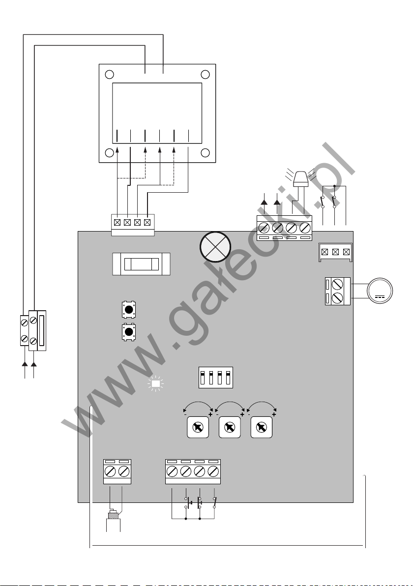
COM
COM
SWO
SWC
P.P.
PHOT
STOP
SHIELD
ANT
ANT
24Vac
1A max
AMPC
AMPO
TCA
F1
S1
DL1
JP4
2AF
1234
LAMP
24Vac/15Wmax
20
20
30
24
0
15
SERVICE LIGHT
24Vac/10W
230Vac
50Hz
N L
P.P
PGM
JP10
JP6
1 2
12 13
5 6 7 8
14151617
18192021
M
ON
F2:1AT (230V)
F2:2AT (115V)
A B C
www.gałecki.pl
3
Page 4

5
Centrali di comando CP.K
www.gałecki.pl
Centrali di comando per motori 24Vdc di potenza non superiore a 120W.
AVVERTENZE GENERALI
a) L’installazione elettrica e la logica di funzionamento devono essere in accordo con le normative vigenti.
b) I conduttori alimentati con tensioni diverse, devono essere sicamente separati, oppure devono essere
adeguatamente isolati con isolamento supplementare di almeno 1 mm.
c) I conduttori devono essere vincolati da un ssaggio supplementare in prossimità dei morsetti.
d) Ricontrollare tutti i collegamenti fatti prima di dare tensione.
e) Controllare che le impostazioni dei Dip-Switch siano quelle volute.
f) Gli ingressi N.C. non utilizzati devono essere ponticellati.
FUNZIONI INGRESSI/USCITE
N° Morsetti Funzione Descrizione
Predisposizione collegamento antenna scheda radioricevente incorpo-
(1-2) Antenna
5 COM Comune per tutti gli ingressi di comando.
6 Passo-Passo Ingresso pulsante passo-passo (contatto N.O.)
7 STOP Ingresso pulsante STOP (contatto N.C.)
8 PHOT
JP7 Motore 24Vdc Connettore ad innesto per collegamento al motore 24Vdc
JP10 Finecorsa
14-15 Lampeggiante Collegamento lampeggiante 24Vac 15W max.
16-17 24 Vac Uscita alimentazione accessori 24Vac/1A max.
JP4 Secondario
J3 Ricevitore Radio Ricevente radio incorporata
rata (1-segnale/2-schermo).
Solo per utilizzo dell’antenna esterna, in questo caso tagliare il tagliare
il lo saldato su “ANT”.
Ingresso collegamento dispositivi di sicurezza, contatto N.C.
(ad es. fotocellule)
In fase di chiusura: l’apertura del contatto provoca l’arresto del motore
e l’inversione istantanea della direzione di marcia dello stesso (apre).
In fase di apertura: non attivo.
Connettore ad innesto per collegamento necorsa:
A: SWC - Finecorsa Chiusura
B: SWO - Finecorsa Apertura
C: COM - Comune necorsa
Collegamento avvolgimento secondario trasformatore.
18 Grigio: Collegato all’uscita 0V
19 Rosso: Velocità rallentamento.
Collegare il Faston all’uscita 15V (velocità rallentamento minima) o
20V (velocità rallentamento massima).
20 Marrone: Collegato all’uscita 24V
21 Bianco :Velocità marcia motore.
Collegare il Faston all’uscita 20V (velocità di marcia minima) o 30V
(velocità di marcia massima).
Vedi paragrafo “Regolazione velocità motore”
Nota: Per il comando dell’automazione durante la fase di installazione è possibile utilizzare il pulsante P.P.
presente sulla centrale.
4
Page 5

Funzione dei Trimmer
www.gałecki.pl
TCA Permette di regolare il tempo di chiusura automatica se attivata dal Dip-Switch N°1.
La regolazione varia da un minimo di 1s ad un massimo di 90s
AMPO Regola la sensibilità del sensore amperometrico di rilevamento ostacolo in fase di apertura.
AMPC Regola la sensibilità del sensore amperometrico di rilevamento ostacolo in fase di chiusura.
Ruotare i trimmer in senso orario (+) per aumentare la coppia, ruotare in senso antiorario (-)
per diminuire la coppia.
La regolazione dei trimmer AMP-O e AMP-C deve essere effettuata nel rispetto delle
normative vigenti.
In caso rilevamento ostacolo:
In fase di apertura ferma il movimento.
In fase di chiusura ferma e riapre l’anta per circa 3s.
Funzione Dip-Switch
DIP 1 “TCA” Abilita o disabilita la chiusura automatica.
Off: chiusura automatica disabilitata
On: chiusura automatica abilitata
DIP 2 “COND.” Abilita o disabilita la funzione condominiale.
Off: Funzione condominiale disabilitata.
On: Funzione condominiale abilitata. L’impulso P.P. o del trasmettitore non ha
effetto durante la fase di apertura e durante la fase TCA (se attivata).
DIP 3 Non utilizzato
DIP 4 “Radio” Abilita o disabilita i trasmettitori a codice programmabile
On: Ricevitore radio abilitato esclusivamente ai trasmettitori a codice variabile
(rolling-code).
Off: Ricevitore abilitato a trasmettitori codice variabile (rolling-code) e
programmabile (autoapprendimento e dip/switch) .
Regolazione della velocità motore
ATTENZIONE! Questa regolazione inuisce sul grado di sicurezza dell’automazione.
Vericare che la forza applicata sull’anta sia conforme con quanto previsto dalle normative vigenti.
Ogni modica della velocità richiede una nuova taratura del sensore amperometrico.
Sul secondario del trasformatore sono presenti 2 morsetti Faston che consentono la selezione della velocità
di marcia e di rallentamento del motore.
Selezione della velocità di marcia motore
Il Faston per la regolazione della velocità di marcia del motore è contraddistinto dal lo di colore Bianco
collegato al morsetto 21.
La velocità di marcia maggiore si ottiene posizionando il Faston sull’uscita 30V, la velocità di marcia ridotta
si ottiene posizionando il Faston sull’uscita 20V.
Selezione della velocità di rallentamento motore
Il Faston per la regolazione della velocità di rallentamento del motore è contraddistinto dal lo di colore
Rosso collegato al morsetto 19.
La velocità di rallentamento maggiore si ottiene posizionando il Faston sull’uscita 20V, la velocità di
rallentamento ridotta si ottiene posizionando il Faston sull’uscita 15V.
Congurazione ricevitore incorporato
La centrale è dotata di un modulo radio incorporato per la ricezione di telecomandi sia a codice sso che a
codice variabile (vedi funzioni dip-switch 4), con frequenza di 433.92MHz.
Per utilizzare un telecomando è prima necessario apprenderlo, la procedura di memorizzazione è illustrata
di seguito, il dispositivo è in grado di memorizzare no a 64 codici diversi.
5
Page 6

7
Memorizzazione di un nuovo trasmettitore con attivazione funzione P.P.
www.gałecki.pl
- Premere 1 volta il pulsante PGM per 1s, il LED DL1inizia a lampeggiare con 1s di pausa.
- Premere entro 10s il pulsante del trasmettitore che si desidera memorizzare con funzione P.P.
Per uscire dalla programmazione, attendere 10s o premere il pulsante PGM per 1s, il LED DL1 riprende a
lampeggiare normalmente con pausa di 3s.
Apprendimento remoto di un trasmettitore
Se si dispone di un trasmettitore già memorizzato è possibile memorizzarne altri senza accedere alla
centrale, procedere come segue:
- Premere il tasto nascosto del trasmettitore già memorizzato, la luce di cortesia inizia al lampeggiare con
pausa di 1s.
- Premere entro 10s il pulsante del trasmettitore che si desidera memorizzare con funzione P.P., la luce di
cortesia si spegne.
Cancellazione di tutti i trasmettitori dalla memoria
- Mantenere premuto il pulsante PGM per 15s, il LED DL1 inizia al lampeggiare velocemente e si spegne a
cancellazione avvenuta.
- Rilasciare il pulsante PGM, la memoria è stata cancella ed il LED DL1 riprende a lampeggiare normalmente
con pausa di 3s.
NOTA:
Per motivi di sicurezza, non è possibile memorizzare trasmettitori durante le fasi apertura/chiusura del
motore.
Se entrando nella procedura di memorizzazione dei trasmettitori il LED DL1 emette un lampeggio lungo e si
spegne, signica che la memoria della ricevente è piena e non è possibile memorizzare altri trasmettitori o
che il trasmettitore utilizzato non è compatibile.
6
Page 7

Control units CP.K
www.gałecki.pl
Control units for 24Vdc motors with powers under 120W.
GENERAL RULES
a) The electrical installation and operating logic must comply with statutory regulations.
b) Cables of different voltages must be physically separated or otherwise adequately screened with
secondary insulation of at least 1 mm.
c) Cables must be secured by additional clamps next to their terminals.
d) Control all wiring connections are correct before powering.
e) Check the Dip-Switch settings are correct.
f) Unused N.C. inputs must be jumpered.
INPUT/OUTPUT FUNCTIONS
Terminals Function Description
Optional antenna connection to built-in radio receiver board (1-
(1-2) Antenna
5 COM Common for all control inputs.
6 Step by Step Step by step button input (N.O. contact)
7 STOP STOP button input (N.C. contact)
8 PHOT
JP7 24Vdc Motor Jack for 24Vdc motor
JP10 Limit switch
14-15 Blinker Blinker connection, 24Vac/15W max.
16-17 24 Vac Accessory power supply 24Vac/1A max.
JP4 Secondary
J3 Radio Receiver Built-in radio receiver
signal/2-screen).
If external antenna connected cut wire welded to “ANT”.
Input for safety devices, N.C. contact (e.g. photocells)
In close cycle: if the contact opens, the motor will stop and will instantly reverse direction (opening).
In open cycle: disabled.
Jack for limit switches:
A: SWC – Close limit switch
B: SWO – Open limit switch
C: COM – Common for limit switches
Secondary circuit of the transformer.
18 Grey: 0V output
19 Red: Slowdown speed.
Connect the Faston to the 15V output (minimum slowdown
speed) or 20V (maximum slowdown speed).
20 Brown: 24V output
21 White: Motor speed.
Connect the Faston to the 20V output (minimum motor speed)
or 30V (maximum motor speed).
See section “Motor speed adjustment ”
N.B.: To control the automation during installation, the Step by Step button on the control unit can be
used.
7
Page 8

9
Trimmer functions
www.gałecki.pl
TCA Adjustment of the automatic close time if enabled by Dip-Switch 1.
Adjustment ranges from 1 sec to max 90 sec
AMP-O Adjustment of the amperometric sensor obstacle detection sensitivity during the open
cycle.
AMP-C Adjustment of the amperometric sensor obstacle detection sensitivity during the close
cycle.
Turn the trimmers clockwise (+) to increase the torque, turn them anticlockwise (-) to reduce
the torque.
Adjustment of trimmers AMP-O and AMP-C must comply with statutory regulations.
If an obstacle is detected:
When opening, the gate is stopped.
When closing, the gate stops and opens for about 3 sec.
Dip-Switch functions
DIP 1 “TCA” Enables or disables automatic closing.
Off: automatic closing disabled
On: automatic closing enabled
DIP 2 “COND.” Enables or disables the high trafc function.
Off: High trafc function disabled.
On: High trafc function enabled. The P.P. (Step-by-step) or transmitter signal is
ignored during the open cycle and the TCA cycle (if enabled).
DIP 3 Not used.
DIP 4 “Radio” Enables or disables transmitters with programmable codes
On: Radio receiver enabled exclusively for rolling-code transmitters.
Off: Receiver enabled for both rolling-code and programmable transmitters
(self-learn and dip-switch) .
Motor speed adjustment
CAUTION! This adjustment strongly affects the safety of the gate automation.
Make sure that the gate thrust complies with statutory regulations.
If the gate speed is changed the amperometric sensor must be calibrated accordingly.
The secondary circuit of the transformer has 2 Faston terminals to select the motor speed and slowdown
speed.
Selecting the motor speed
The Faston for the motor speed adjustment is identied by a white wire connected to terminal 21.
The maximum motor speed is obtained by hooking up the Faston to the 30V output, the minimum motor
speed is obtained by hooking up the Faston to the 20V output.
Selecting the motor slowdown speed
The Faston for the motor slowdown speed adjustment is identied by a red wire connected to terminal 19.
The maximum slowdown speed is obtained by hooking up the Faston to the 20V output, the minimum
slowdown speed is obtained by hooking up the Faston to the 15V output.
Conguration with built-in receiver
The control unit is tted with a built-in radio module for receiving remote controls both with xed codes
and variable codes (see dip-switch 4 functions), with a frequency of 433.92MHz.
For a transmitter to be used, the module rst has to self-learn its code. The memorise procedure is
illustrated below, the module can memorise up to 64 different codes.
Memorising a new transmitter by activating the P.P. function
- Press the PGM button once for 1sec and the Power LED will start blinking at 1 sec intervals.
- Press the transmitter button within 10 sec to memorise with the P.P. (Step-by-step) function.
8
Page 9

To exit the programming procedure wait 10 sec or press the PGM button for 1 sec, the Power LED will
www.gałecki.pl
return to normal blinking at 3 sec intervals.
Remote Learning of a transmitter
If one transmitter has already been memorised others can be memorised without having to access the
control unit as follows:
- Press the hidden key on the memorised transmitter, the courtesy light will start blinking at 1 sec
intervals.
- Within 10 sec press the button of a new transmitter to memorise with Step by Step functioning, the
courtesy light will go out.
Cancelling all transmitters from the memory
- Keep the PGM button pressed for 15 sec, the Power LED will start blinking rapidly and when it goes out
the memory has been erased.
- Release the PGM button, the memory has been cancelled and the Power LED will return to normal
blinking at 3 sec intervals.
N.B.:
For safety reasons, transmitters cannot be memorised during the open/close cycles of the motor.
When entering the memorise transmitter procedure, if the Power LED gives a prolonged blink and then
goes out, this signals that the receiver memory is full and no other transmitters can be memorised or that
the transmitter is not compatible.
9
Page 10

11
Steuerzentralen
www.gałecki.pl
Steuerzentralen für Motoren 24Vdc mit einer Leistung bis 120 W.
ALLGEMEINE HINWEISE
a) Die Elektroinstallation und die Funktionslogik müssen den einschlägigen Normen entsprechen.
b) Verschiedene Spannungen führende Leiter müssen physisch getrennt oder mit einer zusätzlichen Isolierung
von mindestens 1 mm versehen sein.
c) In der Nähe der Klemmen müssen die Leiter zusätzlich xiert werden.
d) Vor dem Zuschalten der Spannung alle Anschlüsse nochmals prüfen.
e) Kontrollieren, ob die Dip-Switches wie gewünscht eingestellt sind.
f) Die nicht verwendeten, normalerweise geschlossenen Eingänge müssen überbrückt werden.
FUNKTIONEN DER EIN-/AUSGÄNGE
Nr. Klemme Funktion Beschreibung
Vorbereitung Antennenanschluss eingebaute Funkempfangspla-
(1-2) Antenne
5 COM Gemeinsam für alle Steuerungseingänge.
6 PP (Schrittschaltung) Eingang Taste Schrittschaltung (Arbeitskontakt)
7 STOPP Eingang Taste STOPP (Ruhekontakt)
8 PHOT
JP7 Motor 24Vdc Steckverbinder für Verbindung zum 24Vdc Motor
JP10 Endschalter
14-15 Blinkleuchte Anschluss Blinkleuchte 24Vac 15W max.
16-17 24 Vac Ausgang Zubehörspeisung 24Vac/1A max.
JP4 Sekundärwicklung
J3 Funkempfänger Eingebauter Funkempfänger
tine (1-Signal/2-Schirm).
Nur für den Einsatz einer externen Antenne; in diesem Fall den
an “ANT” angeschweißten Draht abschneiden.
Eingang Anschluss Sicherheitsvorrichtungen, Ruhekontakt
(z.B. Photozellen)
In Verschlussphase: Das Öffnen des Kontakts löst das Anhalten
des Motors und die umgehende Umkehr seiner Drehrichtung aus
(öffnet).
In Öffnungsphase: Nicht aktiv.
Steckverbinder für Endschalteranschluss:
A: SWC - Endschalter Schließen
B: SWO - Endschalter Öffnen
C: COM - Gemeinsam Endschalter
Anschluss Sekundärwicklung des Transformators.
18 Grau: Angeschlossen an 0V Ausgang
19 Rot: Verlangsamungsgeschwindigkeit.
Den Faston-Verbinder an den 15V (min. Verlangsamungs-
geschwindigkeit) oder 20V Ausgang anschließen (max.
Verlangsamungsgeschwindigkeit).
20 Braun: Angeschlossen an 24V Ausgang
21 Weiß: Motorlaufgeschwindigkeit.
Den Faston-Verbinder an den 20V (min. Laufgeschwindig-
keit) oder 30V Ausgang anschließen (max. Laufgeschwin-
digkeit).
Siehe Absatz “Einstellung der Motorgeschwindigkeit”
CP.K
Hinweis: Für die Steuerung der Automatisierung während der Installation kann die Taste P.P. (Schrittschaltung)
an der Zentrale benutzt werden.
10
Page 11

Funktion der Trimmer
www.gałecki.pl
TCA Ermöglicht die Einstellung der automatischen Verschlusszeit, wenn mittels Dip-Switch Nr. 1
aktiviert. Die Einstellung reicht von min. 1s bis max. 90s
AMP-O Regelt die Empndlichkeit des amperometrischen Sensors zur Erkennung von Hindernissen
während des Öffnens.
AMP-C Regelt die Empndlichkeit des amperometrischen Sensors zur Erkennung von Hindernissen
während des Schließens.
Die Trimmer im Uhrzeigersinn (+) drehen, um das Drehmoment zu erhöhen, und gegen den
Uhrzeigersinn (-), um das Drehmoment zu verringern.
Die Einstellung der Trimmer AMP-O und AMP-C muss unter Einhaltung der einschlägigen
Vorschriften erfolgen.
Wenn ein Hindernis erfasst wird:
Während des Öffnens wird die Bewegung angehalten.
Während des Schließens wird der Torügel angehalten und für zirka 3s wieder geöffnet.
Funktion der Dip-Switches
DIP 1 “TCA” Aktiviert oder deaktiviert das automatische Schließen.
Off: Automatisches Schließen deaktiviert
On: Automatisches Schließen aktiviert
DIP 2 “COND.” Aktiviert oder deaktiviert die Mehrbenutzerfunktion.
Off: Mehrbenutzerfunktion deaktiviert.
On: Mehrbenutzerfunktion aktiviert. Der Impuls der Schrittschaltung oder des Senders
wirkt sich nicht aus während des Öffnens oder während der TCA-Phase (sofern
aktiviert).
DIP 3 nicht verwendet
DIP 4 “Radio” Aktiviert oder deaktiviert die Sender mit programmierbarem Code
On: Funkempfänger ausschließlich für Sender mit variablem Code aktiviert (Rolling-
Code).
Off: Empfänger für Sender mit variablem (Rolling-Code) und programmierbarem
(Selbstlernung und Dip-Switch) Code aktiviert.
Regelung der Motorgeschwindigkeit
ACHTUNG! Diese Regelung beeinusst die Sicherheit der Automatisierung. Sicherstellen, dass die
am Torügel angewandte Kraft den Vorgaben der einschlägigen Normen entspricht.
Jede Änderung der Geschwindigkeit erfordert die erneute Justierung des amperometrischen
Sensors.
An der Sekundärwicklung des Transformators benden sich 2 Faston-Verbinder, welche die Wahl der Laufund Verlangsamungsgeschwindigkeit des Motors ermöglichen.
Wahl der Laufgeschwindigkeit des Motors
Der Faston-Verbinder für die Einstellung der Laufgeschwindigkeit des Motors ist am weißen, mit der
Klemme 21 verbundenen Draht erkennbar.
Die höchste Laufgeschwindigkeit wird erhalten, indem der Faston-Verbinder am 30V Ausgang positioniert
wird, die niedrigere Laufgeschwindigkeit wird erhalten, indem der Faston-Verbinder am 20V Ausgang
positioniert wird.
Wahl der Verlangsamungsgeschwindigkeit des Motors
Der Faston-Verbinder für die Einstellung der Verlangsamungsgeschwindigkeit des Motors ist am roten, mit
der Klemme 19 verbundenen Draht erkennbar.
Die höchste Verlangsamungsgeschwindigkeit wird erhalten, indem der Faston-Verbinder am 20V Ausgang
positioniert wird, die niedrigere Verlangsamungsgeschwindigkeit wird erhalten, indem der Faston-Verbinder
am 15V Ausgang positioniert wird.
Konguration des eingebauten Empfängers
Die Zentrale ist mit einem eingebauten Funkmodul für den Empfang von Fernbedienungen mit xem oder
variablem Code (siehe Funktionen Dip-Switch 4), bei einer Frequenz von 433.92MHz ausgestattet.
Um eine Fernbedienung benutzen zu können, muss diese zunächst programmiert werden.
11
Page 12

13
Das Speicherverfahren wird nachstehend beschrieben. Die Vorrichtung kann bis zu 64 verschiedene Codes
www.gałecki.pl
speichern.
Speichern eines neuen Senders mit Aktivierung der Funktion P.P. (Schrittschaltung)
- 1 Mal die Taste PGM 1s lang drücken, die LED für Power beginnt mit Abständen von 1s zu blinken.
- Innerhalb von 10s die Taste des Senders drücken, die mit der Funktion P.P. belegt werden soll.
Um den Programmierungsmodus zu verlassen, 10s abwarten oder die Taste PGM 1s lang drücken, die LED für
Power blinkt erneut normal mit Abständen von 3s.
Fernprogrammierung eines Senders
Wenn bereits ein Sender eingespeichert ist, können weitere Sender gespeichert werden, ohne auf die
Zentrale zuzugreifen. Dazu wie folgt vorgehen:
- Die verborgene Taste des bereits gespeicherten Senders drücken, die Notbeleuchtung beginnt mit
Abständen von 1s zu blinken.
- Innerhalb von 10s die Taste des Senders drücken, der mit der Funktion P.P. (Schrittschaltung) gespeichert
werden soll, die Notbeleuchtung verlöscht.
Löschen aller Sender aus dem Speicher
- Die Taste PGM 15s lang gedrückt halten, die LED für Power beginnt schnell zu blinken und geht nach
abgeschlossenem Löschen aus.
- Nun die Taste PGM loslassen; der Speicher wurde gelöscht und die LED für Power blinkt wieder normal mit
Abständen von 3s.
NB:
Aus Sicherheitsgründen können die Sender nicht während des Öffnens/Schließens des Motors gespeichert
werden.
Wenn nach Zugriff auf das Speicherverfahren der Sender die LED für Power lange blinkt und dann ausgeht,
bedeutet dies, dass der Speicher des Senders voll ist und keine weiteren Sender eingespeichert werden
können, oder dass der Sender nicht kompatibel ist.
12
Page 13

Logiques de commande CP.K
www.gałecki.pl
Logiques de commande pour moteurs 24 Vcc de puissance non supérieure à 120W.
RECOMMANDATIONS GÉNÉRALES
a) L’installation électrique et la logique de fonctionnement doivent être conformes aux normes en vigueur.
b) Les conducteurs alimentés à des tensions différentes doivent être séparés physiquement ou bien, ils
doivent être isolés de manière appropriée avec une gaine supplémentaire d’au moins 1 mm.
c) Les conducteurs doivent être assurés par une xation supplémentaire à proximité des bornes.
d) Recontrôler toutes les connexions faites avant d’alimenter la logique de commande.
e) Contrôler que les réglages des dip-switchs correspondent à la programmation désirée.
f) Les entrées N.F. non utilisées doivent être shuntées.
FONCTIONS ENTRÉES/SORTIES
N° Bornes Fonction Description
Prévision connexion antenne carte récepteur radio incorporé (1-signal/2-
(1-2) Antenne
5 COM Commun pour toutes les entrées de commande.
6 Pas à pas Entrée touche pas à pas (contact N.O.)
7 STOP Entrée touche STOP (contact N.F.)
8 PHOT
JP7 Moteur 24 Vcc Connecteur embrochable pour connexion au moteur 24 Vcc
JP10 Fin de course
14-15 Clignotant Connexion clignotant 230 Vca 15 W max.
16-17 24 Vca Sortie alimentation accessoires 24 Vca/1 A max.
JP4 Secondaire
J3
Récepteur
Radio
blindage).
Seulement pour utilisation antenne extérieure, dans ce cas couper le l
soudé sur « ANT ».
Entrée connexion dispositifs de sécurité, contact N.F.
(par ex. photocellules)
En phase de fermeture : l’ouverture du contact provoque l’arrêt du moteur
et l’inversion instantanée de son sens de marche (ouverture).
En phase d’ouverture : non active.
Connecteur embrochable pour connexion n de course :
A : SWC – Fin de course fermeture
B : SWO – Fin de course Ouverture
C : COM – Commun n de course
Connexion bobinage secondaire transformateur.
18 Gris : Connecté à la sortie 0V
19 Rouge : Vitesse ralentissement.
Connecter le faston à la sortie 15 V (vitesse ralentissement minimum)
ou 20V (vitesse ralentissement maximum).
20 Brun : Connecté à la sortie 24 V
21 Blanc : vitesse marche moteur.
Connecter le faston à la sortie 20 V (vitesse de marche minimum) ou
30 V (vitesse de marche maximum).
Voir paragraphe « Réglage vitesse moteur »
Récepteur radio incorporé
N.B. : Pour la commande de l’automatisme durant la phase d’installation il est possible d’utiliser la touche
P.P. présente sur la logique de commande.
13
Page 14

15
Fonction des Trimmers
www.gałecki.pl
TCA Permet de régler le temps de fermeture automatique si elle est activée par le dip-switch N°1.
Le réglage varie d’un minimum d’1 s à un maximum de 90 s
AMP-O Règle la sensibilité du capteur ampèremétrique de détection des obstacles en phase
AMP-C Règle la sensibilité du capteur ampèremétrique de détection des obstacles en phase de
Tourner les trimmers dans le sens des aiguilles d’une montre (+) pour augmenter le couple,
Le réglage des trimmers AMP-O et AMP-C doit être effectué dans le respect des
En cas de détection d’obstacle :
En phase d’ouverture, il arrête le mouvement :
En phase de fermeture, arrête et rouvre le vantail pendant environ 3 s.
DIP 1 “TCA” Active ou désactive la fermeture automatique.
Off : fermeture automatique désactivée
On : fermeture automatique activée
DIP 2 “COND.” Active ou désactive le fonctionnement collectif
Off : Fonctionnement collectif désactivé.
On : Fonctionnement collectif activé. L’impulsion P.P. ou de l’émetteur n’a pas
DIP 3 Non utilisé
DIP 8 “Radio” Active ou désactive les émetteurs à code programmable
On : Récepteur radio compatible exclusivement avec les émetteurs à code variable
Off : Récepteur radio compatible avec les émetteurs à code variable (rolling-code) et
ATTENTION ! Ce réglage inuence le degré de sécurité de l’automatisme.
Vérier que la force appliquée sur le portail est conforme aux prescriptions des normes en vigueur.
Toute modication de la vitesse demande un nouvel étalonnage du capteur ampèremétrique.
Sur le secondaire du transformateur se trouvent 2 cosses faston qui permettent la sélection de la vitesse de
marche vitesse et de ralentissement du moteur.
Sélection de la vitesse de marche du moteur
Le faston pour le réglage de la vitesse de marche du moteur est identié par le l de couleur blanche
connecté à la borne 21.
La vitesse de marche supérieure s’obtient en positionnant le faston sur la sortie 30 V, la vitesse de marche
réduite s’obtient en positionnant le faston sur la sortie 20 V.
Sélection de la vitesse de ralentissement du moteur
Le faston pour le réglage de la vitesse de ralentissement du moteur est identié par le l de couleur rouge
connecté à la borne 19.
La vitesse de ralentissement supérieure s’obtient en positionnant le faston sur la sortie 20 V, la vitesse de
ralentissement réduite s’obtient en positionnant le faston sur la sortie 15 V.
La logique de commande est munie d’un module radio incorporé pour la réception d’émetteurs aussi bien à
code xe qu’à code variable (voir fonctions dip-switch 4), à la fréquence de 433,92 MHz.
Pour utiliser un émetteur, il faut d’abord l’enregistrer, la procédure de mémorisation est illustrée ci-après, le
dispositif est en mesure de mémoriser jusqu’à 64 codes différents.
Mémorisation d’un nouvel émetteur avec activation fonction P.P.
- Presser 1 fois la touche PGM pendant 1 s, la LED Power commence à clignoter avec 1 s de pause.
- Presser dans les 10 s la touche de l’émetteur que l’on souhaite mémoriser avec fonction P.P.
d’ouverture.
fermeture.
tourner dans le sens inverse des aiguilles d’une montre (-) pour diminuer le couple.
normes en vigueur.
Fonction dip-switchs
d’effet durant la phase d’ouverture ni durant la phase TCA (si elle est activée).
(rolling-code).
programmable (auto-apprentissage et dip-switch).
Réglage de la vitesse moteur
Conguration récepteur incorporé
14
Page 15

Pour sortir de la programmation, attendre 10 s ou presser la touche PGM pendant 1 s, la LED Power
www.gałecki.pl
recommence à clignoter normalement avec une pause de 3 s.
Apprentissage à distance d’un émetteur
Si on dispose d’un émetteur déjà mémorisé, il est possible d’en mémoriser d’autres sans accéder à la
logique de commande, procéder de la façon suivante :
- Presser la touche cachée de l’émetteur déjà mémorisé, l’éclairage automatique commence à clignoter
avec pause d’1 s.
- Presser dans les 10 s la touche de l’émetteur que l’on souhaite mémoriser avec fonction P.P., l’éclairage
automatique s’éteint.
Effacement de tous les émetteurs de la mémoire
- Maintenir la touche PGM enfoncée pendant 15 s, la LED Power commence à clignoter rapidement et
s’éteint quand l’effacement a eu lieu.
- Relâcher la touche PGM, la mémoire a été effacée et la LED Power recommence à clignoter normalement
avec une pause de 3 s.
N.B. :
Pour des raisons de sécurité, il n’est pas possible de mémoriser des émetteurs durant les phases
d’ouverture et de fermeture.
Si la LED Power émet un long clignotement puis s’éteint quand on entre dans la procédure de mémorisation,
cela signie que la mémoire du récepteur est pleine et qu’il n’est pas possible de mémoriser d’autres
émetteurs ou que l’émetteur n’est pas compatible.
15
Page 16

17
Centralitas de comando CP.K
www.gałecki.pl
Centralitas de comando para motores 24Vdc de potencia no superior a 120W.
ADVERTENCIAS GENERALES
a) Tanto la instalación eléctrica como la lógica de funcionamiento deberán cumplir las normativas
vigentes.
b) Los conductores alimentados con tensiones diversas estarán separados físicamente, o bien estarán
aislados apropiadamente con aislamiento suplementario de al menos 1 mm.
c) Los conductores estarán vinculados con jación suplementaria en proximidad de los terminales.
d) Antes de dar corriente eléctrica, volver a controlar todas las conexiones realizadas.
e) Controlar que las conguraciones de los Dip-Switch sean las deseadas.
f) Las entradas N.C. no utilizadas estarán puenteadas.
FUNCIONES ENTRADAS/SALIDAS
N° terminales Función Descripción
Preparación de la conexión de la antena a la
(1-2) Antena
5 COM Común para todas la entradas de comando.
6 Paso-Paso Entrada del pulsador paso-paso (contacto N.A.)
7 STOP Entrada del pulsador STOP (contacto N.C.)
8 PHOT
JP7 Motor 24Vdc Conector de acoplamiento para conectar el motor 24Vdc
JP10 Fin de carrera
14-15
16-17 24 Vac Salida de alimentación de los accesorios 24Vac/1A máx.
JP4 Secundario
J3 Radiorreceptor Radiorreceptor incorporado
Lámpara destellante
tarjeta del radiorreceptor incorporado (1-señal/2-protección).
Solo para utilizar una antena exterior, en este caso cortar el hilo soldado en “ANT”.
Entrada de la conexión dispositivos de seguridad, contacto N.C. (por
ej. fotocélulas)
En fase de cierre: al abrir el contacto se para el motor y éste invierte
instantáneamente la dirección de marcha (abre).
En fase de apertura: no activo.
Conector de acoplamiento para conectar el n de carrera:
A: SWC - Fin de carrera de cierre
B: SWO - Fin de carrera de apertura
C: COM – Común n de carrera
Conexión de la lámpara destellante 24Vac 15W máx.
Conexión del bobinado secundario transformador.
18 Gris: Conectado a la salida 0V
19 Rojo: Velocidad deceleración.
Conectar el faston a la salida 15V (velocidad de deceleración mí-
nima) o 20V (velocidad de deceleración máxima).
20 Marrón: Conectado a la salida 24V
21 Blanco: Velocidad de marcha del motor.
Conectar el faston a la salida 20V (velocidad de marcha mínima) o
30V (velocidad de marcha máxima).
Véase el párrafo “Regulación de la velocidad del motor”
Nota: Para accionar la automatización en la fase de instalación se utiliza el pulsador P.P. puesto en la
centralita.
16
Page 17

Función de los Trimmer
www.gałecki.pl
TCA Permite regular el tiempo de cierre automático si se activa el Dip-Switch N°1.
La regulación varía de mínimo 1 seg. a máximo 90 segs
AMP-O Regula la sensibilidad del sensor amperimétrico de detección de obstáculo en la fase de
apertura.
AMP-C Regula la sensibilidad del sensor amperimétrico de detección de obstáculo en la fase de
cierre.
Girar los trimmers en el sentido de las agujas del reloj (+) para aumentar el par y en sentido
contrario (-) para disminuirlo.
La regulación de los trimmer AMP-O y AMP-C se realizará en observancia de las
normativas vigentes.
En caso se detecte un obstáculo:
En la fase de apertura para el movimiento.
En la fase de cierre, para y abre otra vez la cancela por cerca de 3 segs.
Función Dip-Switch
DIP 1 “TCA” Habilita o deshabilita el cierre automático.
Off: cierre automático deshabilitado
On: cierre automático habilitado
DIP 2 “COND.” Habilita o deshabilita la función comunidad.
Off: Función comunidad deshabilitada.
On: Función comunidad habilitada. El impulso P.P. o del transmisor no tiene
efecto durante la fase de apertura ni durante la fase TCA (de estar activada).
DIP 3 . No utilizado
DIP 8 “Radio” Habilita o deshabilita los transmisores de código programable
On: Radiorreceptor habilitado exclusivamente con transmisores de código
variable (rolling-code).
Off: Receptor habilitado con transmisores de código variable (rolling-code) y
programable (autoaprendizaje y dip/switch) .
Regulación de la velocidad del motor
¡CUIDADO! Esta regulación afecta al nivel de seguridad de la automatización.
Vericar que la fuerza aplicada a la puerta cumpla las disposiciones de las normativas vigentes.
Cada vez que se modique la velocidad será necesario calibrar de nuevo el sensor amperimétrico.
El secundario del transformador está provisto de 2 terminales de cable faston para la selección de la
velocidad de marcha y de deceleración del motor.
Selección de la velocidad de marcha del motor
El faston para regular la velocidad de marcha del motor se distingue por el hilo blanco conectado al terminal
21.
Se obtiene más velocidad colocando el faston en la salida 30V, y para la velocidad de marcha reducida hay
que colocar dicho cable en la salida 20V.
Selección de la velocidad de deceleración del motor
El faston para regular la velocidad de deceleración del motor se distingue por el hilo rojo conectado al
terminal 19.
La mayor velocidad de deceleración se obtiene colocando el faston en la salida 20V y la velocidad de
deceleración reducida colocando el faston en la salida 15V.
Conguración del receptor incorporado
La centralita incorpora un módulo radio para recibir desde los telemandos el código jo y también el código
variable (véase funciones dip-switch 4), con frecuencia de 433.92MHz.
Para utilizar un telemando hay que aprenderlo primero; a continuación se indica el procedimiento de
memorización, el dispositivo está capacitado para memorizar hasta 64 códigos diversos.
Memorización de un nuevo transmisor con activación de la función P.P.
- Pulsar 1 vez el pulsador PGM por 1 seg., el LED Power comienza a destellar con 1 seg. de pausa.
- Pulsar dentro de 10 segs. el pulsador del transmisor que se desea memorizar con función P.P.
17
Page 18

19
Para salir de la programación esperar 10 segs. o pulsar el pulsador PGM por 1 seg., el LED Power vuelve
www.gałecki.pl
a destellar normalmente con pausa de 3 segs.
Aprendizaje remoto de un transmisor
Si se dispone de un transmisor ya memorizado es posible memorizar otros sin acceder a la centralita, y para
ello hay que hacer lo siguiente:
- Pulsar la tecla oculta del transmisor ya memorizado, la luz de cortesía comienza a destellar con pausa de
1 segundo.
- Pulsar dentro del tiempo límite de 10 segundos el pulsador del transmisor que se quiere guardar con
función P.P., la luz de cortesía se apaga..
Cancelación de la memoria de todos los transmisores
- Mantener presionado el pulsador PGM por 15 segs, el LED Power comienza a destellar rápidamente y se
apaga al realizarse la cancelación.
- Soltar el pulsador PGM, la memoria se ha borrado y el LED Power vuelve a destellar normalmente con
pausa de 3 segs.
NOTA:
Por razones de seguridad, no es posible memorizar los transmisores durante las fases de apertura/cierre
del motor.
Si al entrar en el procedimiento de memorización de los transmisores el LED Power emite un destello
largo y luego se apaga, signica que la memoria del receptor está llena y que no es posible guardar otros
transmisores, o que el transmisor empleado no es compatible.
18
Page 19

Szafy sterownicze CP.K
www.gałecki.pl
Szafy sterownicze dla silników 24Vdc o mocy nie wyższej niż 120W.
OSTRZEŻENIA OGÓLNE
a) Instalacja elektryczna i logika funkcjonowania muszą być zgodne z obowiązującymi normami.
b) Przewody zasilane różnym napięciem, muszą być zycznie oddzielone, lub odpowiednio izolowane
dodatkową izolacją grubości około 1 mm.
c) Przewody muszą być dodatkowo sczepione dławikem w pobliżu zacisków.
d) Należy sprawdzić dodatkowo wszystkie podłączenia dokonane przed włączeniem prądu.
e) Sprawdzić czy nastawienia wszystkich Dip-Switch są zgodne z zamierzonymi.
f) Wejścia N.Z. nie używane muszą być mostkowane.
FUNKCJE WEJŚĆ/WYJŚĆ
Il. zacisków Funkcja Opis
Przystosowanie podłączenia anteny z kartą odbiornika radio
(1-2) Antena
5 COM Wspólna dla wszystkich wejść sterowania
6 Posuw-Posuw Wejście przycisku posuw-posuw (styk N.O.)
7 STOP Wejście przycisku STOP (styk N.Z.)
8 PHOT
JP7 Silnik 24Vdc Łącznik sprzęgowy do połączenia z silnikiem 24Vdc
JP10 Krańcówka
14-15 Światło migające Połączenie światła migającego 24Vac 15W max.
16-17 24 Vac Wyjście zasilania akcesoriów 24Vac/1A max.
JP4 Wtórne
J3 Odbiornik Radio Odbiornik radio wbudowany
wbudowaną (1-sygnał/2-ekran).
Tylko do stosowania anteny zewnętrznej, w tym przypadku należy
przeciąć drut przyspawany do “ANT”
Wejście podłączenia przyrządów zabezpieczających, styk N.Z. (n.p.
fotokomórki)
W fazie zamykania: otwarcie styku powoduje zatrzymanie silnika i
natychmiastową zmianę kierunku jego ruchu (otwiera).
W fazie otwierania: nieczynna.
Łącznik sprzęgowy do połączenia z krańcówką:
A: SWC - Krańcówka Zamykania
B: SWO - Krańcówka Otwierania
C: COM - Wspólne krańcówek
Połączenie wtórnego uzwojenia transformatora.
18 Szary: Połączony z wyjściem 0V
19 Czerwony: Prędkość zwalniania.
Połączyć Faston z wyjściem 15V (prędkość zwalniania minimalna) lub
20V (prędkość zwalniania maksymalna).
20 Brązowy: Połączony z wyjściem 24V
21 Biały: Prędkość ruchu silnika.
Połączyć Faston z wyjściem 20V (prędkość ruchu minimalna) lub 30V
(prędkość ruchu maksymalna).
Zobacz paragraf “Regulacja prędkości silnika”
Uwaga: Do sterowania automatyzmu w fazie instalacji możliwe jest używanie przycisku P.P. z centralki.
19
Page 20

21
Funkcje Trimerów
www.gałecki.pl
TCA Pozwala regulować czas zamykania automatycznego jeśli funkcja włączana jest przez Dip-
Switch N°1.
Regulacja ma zakres od minimum 1s do maksymum 90s
AMP-O Reguluje wrażliwość czujnika amperometrycznego na wyczuwanie przeszkody w fazie
otwierania.
AMP-C Reguluje wrażliwość czujnika amperometrycznego na wyczuwanie przeszkody w fazie
zamykania.
Pokręcać trimer w kierunku wskazówek zegara (+) dla zwiększenia pary, pokręcać w
kierunku odwrotnym do ruchu wskazówek zegara (-) by zmniejszyć parę.
Regulacja trimerów AMP-O i AMP-C musi być dokonywana zgodnie z obowiązującymi
normami.
W przypadku wyczucia przeszkody:
W fazie otwierania zatrzymuje ruch.
W fazie zamykania zatrzymuje i otwiera skrzydło na około 3s
Funkcje Dip-Switch
DIP 1 “TCA” Włącza lub wyłącza zamykanie automatyczne.
Off: zamykanie automatyczne wyłączone
On: zamykanie automatyczne włączone
DIP 2 “COND.” Włącza i wyłącza funkcję współużytkową.
Off: Funkcja współużytkowa wyłączona.
On: Funkcja współużytkowa włączona. Impuls P.P. lub przekaźnika pozostaje
bez efektu podczas fazy otwierania i podczas fazy TCA (jeśli czynna).
DIP 3 Nie używany
DIP 4 “Radio” Włącza lub wyłącza przekaźniki na kod programowany
On: Odbiornik radio współpracujący wyłącznie z przekaźnikami na kod zmienny
(rolling-code).
Off: Odbiornik współpracujący z przekaźnikami na kod zmienny (rolling-code) i
programowany (samowzbudny i dip/switch) .
Regulacja prędkości silnika
UWAGA! Regulacja ta wpływa na stopień bezpieczeństwa automatyzmu.
Sprawdzić czy siła oddziaływania na skrzydło bramy jest zgodna z obowiązującymi normami.
Każda zmiana prędkości wymaga nowego wzorcowania czujnika amperometrycznego.
Na wtórnym uzwojeniu transformatora występują 2 przyłącza zaciskowe Faston umożliwiające nastawianie
prędkości ruchu i prędkości zwalniania silnika.
Nastawianie prędkości ruchu silnika
Faston do regulacji prędkości ruchu silnika odróżnia się drutem w kolorze Białym połączonym z zaciskiem
21.
Większą prędkość ruchu otrzymuje się przez ustawienie Fastona na wyjściu 30V, mniejszą prędkość ruchu
otrzymuje się przez ustawienie Fastona na wyjściu 20V.
Nastawianie prędkości zwalniania
Faston do regulacji prędkości zwalniana silnika odróżnia się drutem w kolorze Czerwonym połączonym z
zaciskiem 19.
Większą prędkość zwalniania otrzymuje się przez ustawienie Fastona na wyjściu 20V, mniejszą prędkość
zwalniania otrzymuje się przez ustawienie Fastona na wyjściu 15V.
20
Page 21

Konguracja odbiornika wbudowanego
www.gałecki.pl
Szafa sterownicza posiada wbudowany moduł radiowy do odbierania poleceń zarówno na kod stały jak i
na kod zmienny (zobacz funkcje dip-switch 8), z częstotliwością 433.92MHz.
W celu używania pilota należy wcześniej zapoznać się z jego funkcjonowaniem, proces utrwalania w
pamięci przedstawiony jest poniżej, przyrząd jest w stanie zapamiętać aż do 64 kodów odmiennych.
Zapamiętywanie nowego przekaźnika przez włączenie funkcji P.P.
- Przycisnąć tylko 1 raz na 1s przycisk PGM, LED Power rozpocznie miganie z przerwami w odstępach
co 1s
- Przycisnąć w ciągu 10s przycisk przekaźnika który zamierza się utrwalić w pamięci za pomocą funkcji
P.P.
By wyjść z programowania, odczekać 10s lub przycisnąć przycisk PGM na 1s, LED Power wznowi
miganie normalne z przerwami co 3s.
Zdalne przyjmowanie przekaźnika
Jeśli dysponuje się przakaźnikiem już wcześniej zapisanym w pamięci to możliwe jest przyjmowanie
innych przekaźników bez konieczności używania centralki, w tym przypadku postępuje się według
poniższych wskazówek:
- Nacisnąć kryty przycisk zapisanego już przekaźnika, światło rozpoznawcze rozpoczyna miganie z
przerwą co 1 sek.
- Nacisnąć w przeciągu 10 sek przycisk przekaźnika który zamierza się zapisać z funkcją P.P., światło
rozpoznawcze zgaśnie.
Wycofanie z pamięci wszystkich przekaźników
- Trzymać naciśnięty przycisk PGM przez 15s, LED Power zacznie szybko migać i zgaśnie po
zakończeniu wycofywania z pamięci.
- Zwolnić przycisk PGM, pamięć została opróżniona i LED Power wznawia miganie normalne z przetwami
co 3s.
UWAGA:
Z racji na bezpieczeństwo, nie można utrwalać w pamięci przekaźników podczas faz otwierania/
zamykania silnika.
Jeśli podczas procesu wprowadzania do pamięci przekaźników LED Power zaświeci się na dłużej
i zgaśnie, oznacza to że pamięć odbiornika jest przepełniona i nie jest w stanie zapamiętać innych
przekaźników lub że stosowany przekaźnik nie jest kompatybilny.
21
Page 22

22
23
www.gałecki.pl
Page 23

www.gałecki.pl
23
Page 24

AUTOMATISMI BENINCÀ SpA - Via Capitello, 45 - 36066 Sandrigo (VI) - Tel. 0444 751030 r.a. - Fax 0444 759728
www.gałecki.pl
 Loading...