

Page 1
L8542772 ITA/ENG/ESP
02/2013 rev 2
CP.BULLOCK
CP.BULLOCK
115
UNIONE NAZIONALE COSTRUTTORI
AUTOMATISMI PER CANCELLI, PORTE
SERRANDE ED AFFINI
Page 2

12
EC Declaration of conformity
Declaration pursuant to Directives 2004/108/EC(EMC); 2006/95/EC(LVD)
Manufacturer:
Automatismi Benincà SpA
Address:
Via Capitello, 45 - 36066 Sandrigo (VI) - Italy
Declares that the product:
Command central for 1/2 24Vdc motor, for single or sliding doors: CP.BULLOCK
is compliant with the conditions of the following EC Directives:
• DIRECTIVE 2004/108/EC OF THE EUROPEAN PARLIAMENT AND COUNCIL of December 15 2004 regarding
the approximation of the legislations of the member States relative to electromagnetic compatibility and that repeals directive
89/336/CEE, according to the following concurred norms:
EN 61000-6-2:2005, EN 61000-6-3:2007.
• DIRECTIVE 2006/95/EC OF THE EUROPEAN PARLIAMENT AND THE COUNCIL of December 12 2006 concerning the approximation of the legislations of the member States relative to electrical material destined to be used within certain
voltage limits, according to the following concurred regulations:
EN 60335-1:2002 + A1:2004 + A11:2004 + A12:2006 + A2:2006 + A13:2008; EN 60335-2-103:2003.
if applicable :
• DIRECTIVE 1999/5/EC OF THE EUROPEAN PARLIAMENT AND THE COUNCIL of March 9 1999 regarding radio
devices and terminal and telecommunications devices and the reciprocal recognisances of their conformity, according to the
following concurred regulations: ETSI EN 301 489-3 V1.4.1 (2002) + ETSI EN 301 489-1 V1.4.1 (2002) + ETSI EN 300 220-3
V1.1.1 (2000) + EN 60950-1 (2001)
Benincà Luigi, Legal manager.
Sandrigo, 02/11/2010.
WARNINGS
This manual has been especially written to be use by qualified
fitters.
None of the information provide in this manual can be considered
as being of interest for the end users.
Preserve this manual for future needs.
The technician has to furnish all the information related to the step
by step function, the manual and the emergency function of the
operator, and to deliver the manual to the final user.
;
Foresee on the supply net an onnipolar switch or selector with distance of the contacts equal or superior
to 3 mms.
Verify that of the electrical system there is an awry differential
interrupter and overcurrent protection.
Some typologies of installation require the connection of the
shutter to be link at a conductive mass of the ground according
to the regulations in force.
The electrical installation and the operating logic must comply
with the regulations in force.
The leads fed with different voltages must be physically separate,
or they must be suitably insulated with additional insulation of
at least 1 mm.
The leads must be secured with an additional fixture near the
terminals.
During installation, maintenance and repair, interrupt the power
supply before opening the lid to access the electrical parts
Check all the connections again before switching on the power.
The unused N.C. inputs must be bridged.
The descriptions and the present illustrations in this manual are
not binding. Leaving the essential characteristics of the product
unchanged, the manufacturer reserves himself the right to bring
any change of technical, constructive or commercial character
without undertaking himself to update the present publication.
Page 3
13
1
2
3
4
5
PHOT
STOP
PP
RXTX
24V
-
+
BLINK
SHHIELD
ANT
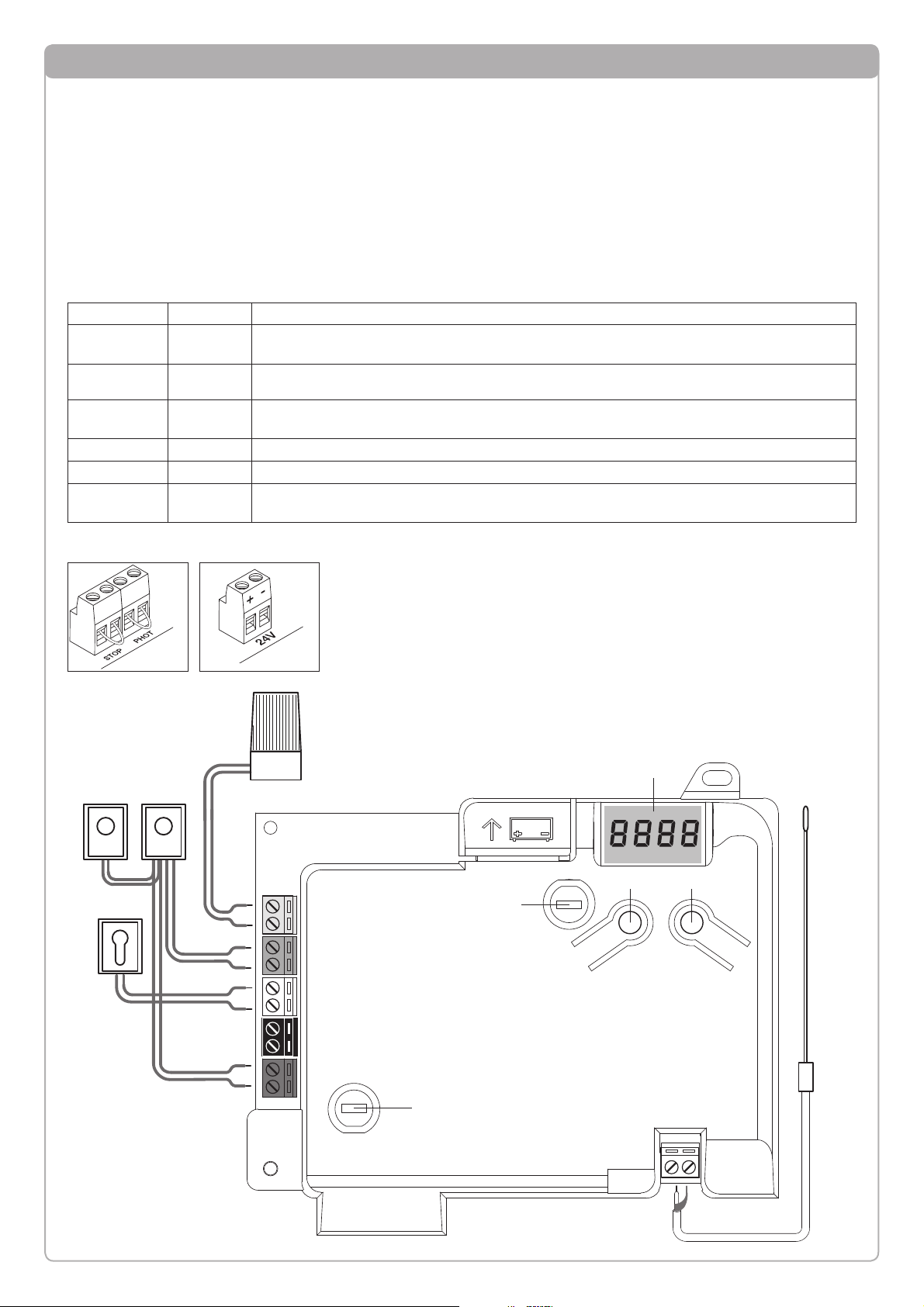
Control unit CP.BULLOCK connections
Except for the mains connection cable, all electric connections
have a voltage of 24V and can also be performed by unqualified staff.
Connect all accessories making reference to the layout in figure
33 and to the “Electric connections” paragraph, for that concerning the types of cable.
To make connection easier, the accessory clamps have colours
that correspond to those of the control unit.
Fig.1
KEY:
1 Line protection fuse
2 Accessories protection fuse
3 “PGM” programming button
4 Programming button “5”
5 LCD
A B
DESCRIPTION OF THE TERMINAL BOARDS
CLAMP COLOUR DESCRIPTION
PHOT GREEN
NC input from the RX photocell. The two clamps are connected to each other by a wire (ref. “A”).
Remove this wire only if the photocell is connected.
STOP BLACK
STOP input NC contact for auxiliary “STOP” command (optional). The two clamps are connected to
each other by a wire (ref. “A”). Remove this wire only if a device is connected to this input.
PP WHITE
Step-by Step’ command input from the key selector. At every impulse sent from the selector a
sequence of commands, which can be configured using the PP function, is performed cyclically.
24V YELLOW 24Vdc output for photocells power supply. Respect the polarities + and - in the connections (ref “B”).
BLINK RED 24Vdc flashing light connection output
SHIELD/ANT BLUE
Connection of the aerial built-in the flashing light.
When connecting the RG58 cable, the external shield must be connected to the SHIELD clamp.
Page 4
14
Programming of the control unit allows the regulation of all
parameters indispensable for the correct functioning of the
automation.
Programming takes place by means of a series of menus that
can be selected from the LCD. A function corresponds to every menu, which will be described successively.
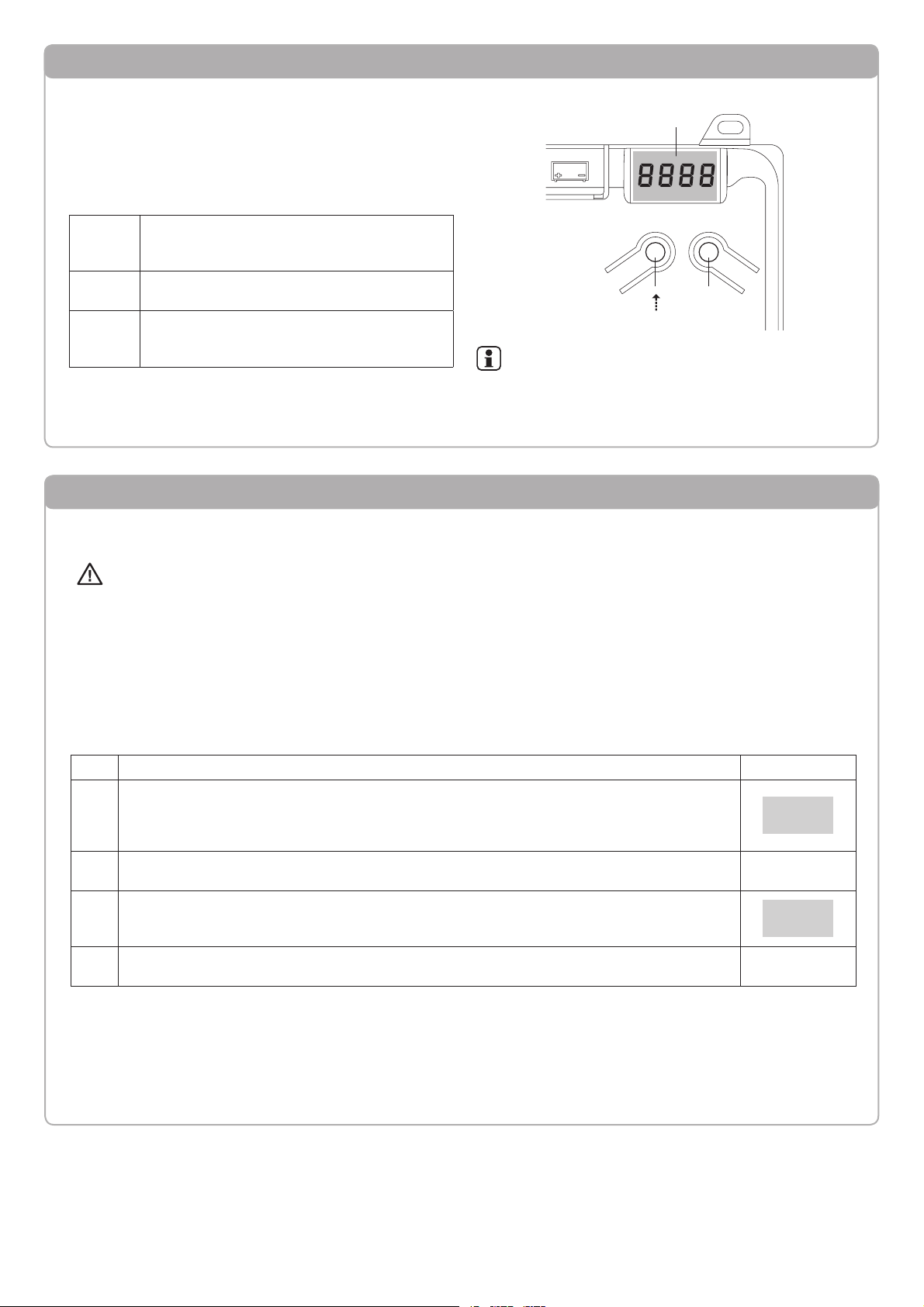
PGM
The “PGM” button allows to enter programming,
select the pre-selected menu and confirm the
value selected.
5
The “5” button allows to scroll the various items
in the menu and the values to be set cyclically.
PGM+5
By pressing “5” and “PGM” at the same time,
return to the upper level of the menu or, if already
at the first level, exit programming.
Programming the CP.BULLOCK control unit - Introduction
LCD
PGM
With the display off, the “5” button performs a Stepby-Step command. This function can be useful during
the programming and inspection phases.
Pressing the PGM button causes the immediate stop
of any leaf movement.
Self-regulation of the functioning parameters (AUTO)
The first and most important function to program is the self-regulation of the parameters, which allows the control unit to automatically set the end run points, the torque applied to the leaf and the torque in the slowing phase*.
During the autoset operations, the control unit automatically performs several opening and closure manoeuvres.
Before proceeding, check that no person, animal or obstacle is or can be in the door manoeuvre area.
All the accessories provided for the system should be already connected to the control unit. If further accessories should
be added, self-adjustment must be repeated.
Proceed as follows:
1- Apply mains power supply to the automation via the pre-wired socket, using an extension if necessary.
2- Release the leave, take it manually to about half of the run and block it again.
3- Start the autoset phase as described below. As soon as the first manoeuvre starts, carefully check that the leaf moves in the
closure direction.
If this is not the case, press "5" and “PGM” at the same time to interrupt the autoset. The display shows the ERR message. Use
the movement direction reverse button (MINV menu) and change the direction of movement.
1 Press the button [PGM] to access programming.
PGM
2 The display shows AUTO, select Auto by pressing the [PGM] button.
AUTO
3
AUTO starts to flash slowly. Press and hold the [PGM] key, after 5 seconds AUTO starts to flash
quickly, release the key only when the display shows the PRG message.
4
The self-regulation phase starts, the display shows PRG. The control unit commands different
opening and closing manoeuvres at various speeds.
At the end of the manoeuvre the display shows “OK”
PRG
5
The control unit goes back to the AUTO menu. To exit programming, press the [PGM] and [5] buttons at the same time or, alternatively, remove the power supply or wait 60 seconds.
PGM+5
* The slowing phase must be activated via the TSM parameter. The control unit is supplied with the parameter set at 0 (Off); the
AUTO function does not activate slowing but is limited to defining a suitable torque value.
The intervention of the photocells or any other command from the transmitter or key selector, interrupts the autoset
phase, displaying the message ERR1/2/3. The procedure must therefore be repeated.
Every self-regulation procedure overwrites the previous one.
Perform an autostop procedure after every maintenance intervention or modification of the door.
Page 5

15
Regulation of the motor thrust (PMOT)
The force applied is normally set automatically by the control unit during the self-regulation phase (AUTO).
This menu can be used to modify that set by the control unit, to make up for a friction point for example.
1
Press the [PGM] button to access programming or if the control unit is already in the programming menu, press [5] until the PMOT function is displayed.
PMOT
pmot
PMOTPMOT
2
Press the [PGM] button to enter the PMOT regulation.
The display shows the current value of the PMOT parameter.
Use the [5] key to select one of these values:
1 low motors torque
2 medium/low motors torque
3 medium/high motors torque
4 high motors torque (default setting)
0001
0004
3 Confirm the desired value using the [PGM] key, the display shows PRG.
PRG
4
The control unit goes back to the PMOT menu. To exit programming, press the [PGM] and [5] buttons at the same time or, alternatively, remove the power supply or wait 60 seconds.
PGM+5
Regulation of the automatic closure time (TCA)
The automatic closure function allows to set a time which, on expiry, if the leaf is in the open position the control unit autonomously commands a closure manoeuvre.
With this function active, if you forget to give the closure command or in the case of simultaneous commands, the control unit
closes the leaf after the set time.
The factory setting envisions 30 seconds before automatic closure.
1
Press the [PGM] button to access programming or if the control unit is already in the programming
menu, press [5] until the TCA function is displayed.
TCA
2
Press the [PGM] button to enter the TCA parameter regulation.
The display shows the current value of the TCA parameter.
Use the [5] key to select one of these values:
0 The TCA function is deactivated.
1 The pause time is set at 10 seconds (default setting
2 The pause time is set at 30 seconds)
3 The pause time is set at 60 seconds
4 The pause time is set at 90 seconds
0000
0004
3 Confirm the desired value using the [PGM] key, the display shows PRG.
PRG
4
The control unit goes back to the TCA menu. To exit programming, press the [PGM] and [5] buttons at the same time or, alternatively, remove the power supply or wait 60 seconds.
PGM+5
Page 6

16
Step-by-Step functioning mode (PP)
It is possible to select two different modes of the Step-by Step command sent from the transmitter or the key selector.
Every time the button is pressed in the default mode, the following progression of commands is performed cyclically:
OPEN>STOP>CLOSE>STOP>OPEN> and so on.
The sequence can be modified by eliminating the intermediate STOP commands: OPEN>CLOSE>OPEN> and so on.
1
Press the [PGM] button to access programming or if the control unit is already in the programming
menu, press [5] until the PP function is displayed.
PMOT
PP
2
Press the [PGM] button to enter the PP regulation.
The display shows the current value of the PP parameter.
Use the [5] key to select one of these values:
ON OPEN>CLOSE>OPEN functioning (default)
OFF OPEN>STOP>CLOSE>STOP>OPEN> functioning
on
off
3 Confirm the desired value using the [PGM] key, the display shows PRG.
PRG
4
The control unit goes back to the PP menu. To exit programming, press the [PGM] and [5] buttons
at the same time or, alternatively, remove the power supply or wait 60 seconds.
PGM+5
Pre-flashing functioning mode (Pre)
An imminent manoeuvre warning mode can be set through the pre-flashing function.
Once activated, the flashing light switches on 3 seconds before the door starts to move.
1
Press the [PGM] button to access programming or if the control unit is already in the programming
menu, press [5] until the Pre function is displayed.
PMOT
Pre
2
Press the [PGM] button to enter the Pre regulation.
The display shows the current value of the Pre parameter.
ON pre-flashing activated
OFF pre-flashing deactivated (default)
on
off
3 Confirm the desired value using the [PGM] key, the display shows PRG.
PRG
4
The control unit goes back to the PRE menu. To exit programming, press the [PGM] and [5] buttons at the same time or, alternatively, remove the power supply or wait 60 seconds.
PGM+5
Regulation of the slowing time (TSM)
If the leaf is to slow for a few seconds before the end run intervention, select one of the values available, as described below.
1
Press the [PGM] button to access programming or if the control unit is already in the programming
menu, press [5] until the TSM function is displayed.
PMOT
TSM
PMOTPMOT
2
Press the [PGM] button to enter the TSM regulation.
The display shows the current value of the TSM parameter.
Use the [5] key to select one of these values:
0 Slowing not active (default setting)
1 3 slowing seconds
2 5 slowing seconds
3 7 slowing seconds
4 10 slowing seconds
0000
0004
3 Confirm the desired value using the [PGM] key, the display shows PRG.
PRG
4
The control unit goes back to the TSM menu. To exit programming, press the [PGM] and [5] buttons at the same time or, alternatively, remove the power supply or wait 60 seconds.
PGM+5
After every modification of the value of this parameter, it is necessary to proceed with a new self-learning phase
Page 7

17
Condominium function (IBL)
If used in condominiums, it may be preferable that further commands given during the opening phase are ignored.
This function can result useful if many users are involved, in a way to prevent several opening commands, given at the same
time, causing the movement to stop.
1
Press the [PGM] button to access programming or if the control unit is already in the programming
menu, press [5] until the IBL function is displayed.
PMOT
IBL
2
Press the [PGM] button to enter the IBL regulation.
The display shows the current value of the IBL parameter.
ON IBL mode activated
OFF IBL mode deactivated (default)
on
off
3 Confirm the desired value using the [PGM] key, the display shows PRG.
PRG
4
The control unit goes back to the IBL menu. To exit programming, press the [PGM] and [5] buttons
at the same time or, alternatively, remove the power supply or wait 60 seconds.
PGM+5
Selection of photocells functioning (PHCL)
It is possible to select the functioning mode of the photocells connected to the PHOT input. Normally, the photocells are active
only in the closing phase, to allow the access of the vehicle even when the gate is not completely open. If this intervention is also
desired in the opening phase, modify the parameter as follows:
1
Press the [PGM] button to access programming or if the control unit is already in the programming
menu, press [5] until the PHCL menu is displayed.
PMOT
PHCL
2
Press the [PGM] button to enter the PHCL regulation.
The display shows the current value of the PHCL parameter.
Use the [5] key to select one of these values:
ON Photocells active in the opening and closing phase
OFF Photocells only active in the closure phase (default)
on
off
3 Confirm the desired value using the [PGM] key, the display shows PRG.
PRG
4
The control unit goes back to the PHCL menu. To exit programming, press the [PGM] and [5] buttons at the same time or, alternatively, remove the power supply or wait 60 seconds.
PGM+5
Selection of direction of rotation of the motor (MINV)
The sliding gates can open by sliding to the right or to the left, as indicated in Figure.
DX
SX
OPEN
OPEN
DX
The direction of rotation may have to be inverted according to the position of the motor.
1
Press the [PGM] button to access programming or if the control unit is already in the programming
menu, press [5] until the MINV menu is displayed.
PMOT
MINV
2
Press the [PGM] button to enter the MINV regulation.
The display shows the current value of the MINV parameter.
Use the [5] key to select one of these values:
C__O Motor with opening to the right
O__C Motor with left opening - default setting-
o--c
c--o
3 Confirm the desired value using the [PGM] key, the display shows PRG.
PRG
4
The control unit goes back to the MINV menu. To exit programming, press the [PGM] and [5] buttons at the same time or, alternatively, remove the power supply or wait 60 seconds.
PGM+5
Page 8

18
Energy saving functioning mode (ESA)
With the “ESA” energy saving function activated ,when a full opening or closing cycle is complete the control panel is in a
condition of full energetic efficiency ,reducing at the minimum the energetic consumption by taking off power supply from the
transformer and accessories.
1
Press the [PGM] button to access programming or if the control unit is already in the programming
menu, press [5] until the ESA function is displayed.
PMOT
ESA
2
Press the [PGM] button to enter the ESA regulation.
The display shows the current value of the ESA parameter.
ON ESA mode activated (default)
OFF ESA mode deactivated
on
off
3 Confirm the desired value using the [PGM] key, the display shows PRG.
PRG
4
The control unit goes back to the ESA menu. To exit programming, press the [PGM] and [5] buttons
at the same time or, alternatively, remove the power supply or wait 60 seconds.
PGM+5
Note :The ESA function does not work when the charger is in charging mode.
The ESA function must be disabled when there is the need of keeping the accessories output always activated ,for example
when a 24Vdc keypad or any other device that needs constant power supply is linked to the control panel.
Resetting the control unit (Res)
This function annuls all settings made, taking the control unit back to the initial conditions.
It also deletes the settings of the autostart procedure.
NOTE: Any remote controls memorised in the radio receiver are not deleted.
1
Press the [PGM] button to access programming or if the control unit is already in the programming
menu, press [5] until the Res function is displayed.
PMOT
RES
2 Press and hold [PGM], the RES message starts to flash quickly.
3
Release the [PGM] button when the PRG message is displayed.
The control unit is now taken to factory values.
PRG
4
The control unit goes back to the RES menu. To exit programming, press the [PGM] and [5] buttons at the same time or, alternatively, remove the power supply or wait 60 seconds.
PGM+5
Memorising new transmitters (RADI>PP)
To memorise new transmitters with Step-by-Step function for the automation command, proceed as follows:
1
Press the [PGM] button to access programming or if the control unit is already in the programming
menu, press [5] until the Radi menu is displayed.
PMOT
Radi
2
Press the [PGM] button to enter the Radi function.
The display shows the first sub-menu PP.
PP
3
Press the [PGM] button to enter the PP function.
The display shows the PUSH message.
Push
4
Press the BY transmitter button that is to be associated to the Step-by-Step function within 5
seconds.
5 The display shows PRG to confirm memorisation.
PRG
6
The control unit goes back to the RADI>PP menu. To go back to the RADI menu, press the [PGM]
and [5] buttons at the same time. To exit programming, press the [PGM] and [5] buttons at the
same time again or, alternatively, remove the power supply or wait 60 seconds.
PGM+5
Page 9

19
Memorising pedestrian function (RADI>Ped)
The pedestrian function can be associated to any transmitter button. The pedestrian function envisions partial opening for 7
seconds, proceed as follows:
1
Press the [PGM] button to access programming or if the control unit is already in the programming
menu, press [5] until the Radi menu is displayed.
PMOT
Radi
2
Press the [PGM] button to enter the Radi function.
The display shows the first sub-menu PP.
Press [5] to display the Ped sub-menu.
Ped
3
Press the [PGM] button to enter the Ped function.
The display shows the flashing PUSH message.
Push
4
Press the BY transmitter button that is to be associated to the Pedestrian function within 10
seconds (e.g. if key 1 has already been associated to the Step-by-Step function, key T2 can be associated to the Pedestrian function).
5 The display shows OK to confirm memorisation.
ok
6
The control unit goes back to the RADI>PED menu. To go back to the RADI menu, press the [PGM]
and [5] buttons at the same time. To exit programming, press the [PGM] and [5] buttons again at
the same time again or, alternatively, remove the power supply or wait 60 seconds.
PGM+5
Deleting transmitters (RADI>CLR)
Proceed as follows to delete a transmitter already inserted in the memory:
1
Press the [PGM] button to access programming or if the control unit is already in the programming
menu, press [5] until the Radi menu is displayed.
PMOT
Radi
2
Press the [PGM] button to enter the Radi function.
The display shows the first sub-menu PP.
Press [5] to display the CLR sub-menu
Clr
3
Press the [PGM] button to enter the CLR function.
The display shows PUSH.
Push
4 Press any transmitter button BY that is to be deleted within 5 s.
5 The display shows OK to confirm cancellation.
OK
6
The control unit goes back to the RADI>CLR menu. To go back to the RADI menu, press the [PGM]
and [5] buttons at the same time. To exit programming, press the [PGM] and [5] buttons again at
the same time again or, alternatively, remove the power supply or wait 60 seconds.
PGM+5
Page 10

20
Remote controls quick duplication
If you have a transmitter that is already memorised (TX1), it can be duplicated (TX2) without accessing the control unit for programming, proceed as follows:
1
Give an opening command and wait till the leaf is in full opening position using a transmitter already
stored in memory (TX1), (TCA function must be enabled ).
PMOT
2
Press the hidden key of the transmitter ,the code of which has already been stored in memory
(TX1)
TX1
3
Within 5 seconds ,press the already memorized transmitter key corresponding to the channel to be
matched to the new transmitter. The flashing light switches on.
TX1
4 Within 10 seconds ,press the hidden key of the new transmitter (TX2).
TX2
5
Within 5 seconds ,press the key of the new transmitter to be matched to the channel to be matched
at the item 2 ,the flashing light switches off.
TX2
6 The receiver stores the new transmitter code and exits from the programming mode immediately.
Complete deletion of the receiver memory (RADI>RTR)
To delete the memory completely, eliminating all previously-inserted remote controls, proceed as follows:
1
Press the [PGM] button to access programming or if the control unit is already in the programming
menu, press [5] until the Radi menu is displayed.
PMOT
Radi
2
Press the [PGM] button to enter the Radi function.
The display shows the first sub-menu PP.
Press [5] three times to display the RTR sub-menu
rtr
3
Press the [PGM] button to enter the RTR function, the RTR message starts to flash slowly.
Press [PGM], the PRG message is displayed and deleting starts.
4
When the PRG message switches off, the display shows the OK message for about 2 seconds. All
remote controls are now deleted from the memory.
PRG
6
The control unit goes back to the RADI>RTR menu. To go back to the RADI menu, press the
[PGM] and [5] buttons at the same time. To exit programming, press the [PGM] and [5] buttons at
the same time again or, alternatively, remove the power supply or wait 60 seconds.
PGM+5
Page 11

21
What to do if...
Below find the most common functioning problems and the relative solutions. :
Problem Cause Solution
The automation does not work
There is no mains power supply
--------------------------------------------------
The control unit is not connected
--------------------------------------------------
The photocells are engaged
-------------------------------------------------One or more protection fuses have intervened
Check for the presence of mains power
supply
--------------------------------------------------
Check all connections to the control unit
-------------------------------------------------Check that there is no obstacle between the
photocells
-------------------------------------------------Check the integrity of the fuses and replace
them if necessary.
The automation does not work using the
remote control.
The remote control battery is flat, the remote
control LED flashes quickly
--------------------------------------------------
the remote control has not been memorised
Replace the remote control batteries
--------------------------------------------------
Memorise the remote control.
The automation does not work using the key
selector
The selector is not connected correctly or
is faulty.
Check the key selector connections or replace
them is faulty
The gate stops in the opening or closure
phase, inverts the movement for a few seconds and then stops.
The obstacle detection sensor has intervened
If no obstacles are present, release the
motor and check for the presence of friction
points. Perform a new self-learning.
Increase the value of the PMOT parameter
The door does not close
STOP input active.
-------------------------------------------------Obstacle between the photocells or photocells broken
Check the connections of the STOP input
-------------------------------------------------Remove the obstacle or check the photocells
The flashing light does not switch on
The bulb has blown
--------------------------------------------------
The flashing light is not connected correctly
Replace the bulb
--------------------------------------------------
Check the connections.
The automatic system does not operate.
The message PHOT-C is displayed.
The photocells detect an obstacle
-------------------------------------------------The photocells have been connected after the
self-adjustment phase
Chack any obstacle present
-------------------------------------------------Repeat the self-adjustment procedure.
The control unit LCD displays several messages during normal functioning and in the case of breakdown:
Message Description
ERR
Stop the autoset phase by pressing the [PGM] and [5] buttons at the same time
ERR1
Motor error. Check the motor connection or broken motor
ERR2
Photocell error. Check the photocell connections or broken photocells.
ERR3
PP input activation error during the autoset phase
ERR4
STOP input activation error during the autoset phase
PP
PP inlet active
STOP
STOP input active
PHOT
Photocell input active
OPEN
Start of opening manoeuvre
Clos
Start of closure manoeuvre
alt
Stop the manoeuvre by means of the PP command or STOP input.
BATT
The automation is functioning with the buffer battery in the absence of mains power supply (only with CB.BY accessory installed).
Page 12

AUTOMATISMI BENINCÀ SpA - Via Capitello, 45 - 36066 Sandrigo (VI) - Tel. 0444 751030 r.a. - Fax 0444 759728
 Loading...