

Page 1
L8542928
11/2011 rev 2
CELL.P
UNIONE NAZIONALE COSTRUTTORI
AUTOMATISMI PER CANCELLI, PORTE
SERRANDE ED AFFINI
Page 2
3
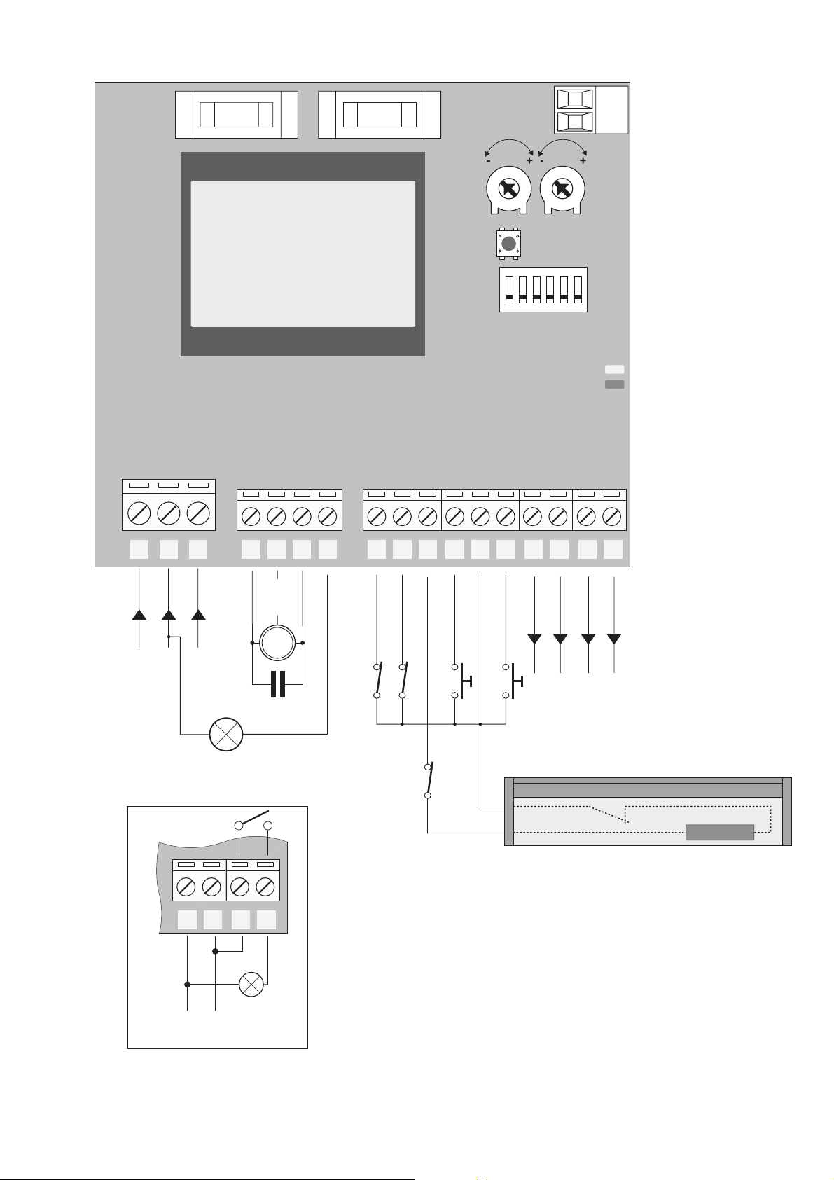
DL1
DL2
N
G N D
L
LAMP 115/230Vac
40W max
SWO
SWC
DAS
PHOT
CHIUDE
COM
APRE
SCA
SCA
P1
SW
1 6
TW TCA
1 2 3 4 5 6 7 8 9 10 11 12 13 14 15
18 19
F3: F6,3A
F2: F315 mA
F3
F2
8K2
R
24Vac
300mA max
16 17
14 15 16 17
SCA 24Vac
3W max
COM
M
C
Page 3
8
CELL.P control unit with microcontroller
INPUT/OUTPUT FUNCTIONS
Terminals Function Description
1, 2, 3 Power supply Input, 230VAC 50/60Hz
(1-Phase/2-Neutral/GND-Ground connection)
4, 5, 6 Motor Connection to motor:
(MOT-move/COM-Common/MOT-move)
7 LAMP Output, connection to Flashing light: 230 Vac 40W max.
8 SWO Input, OPENING limit switch (Normally Closed contact)
9 SWC Input, CLOSING limit switch (Normally Closed contact)
10 DAS/ PHOT Safety edge or photocell Input
See DIP-SWITCH 3.
TECHNICAL DATA
Control unit power supply
230 Vac
Power supply
230 Vac 50/60 Hz or 115Vac 50/60Hz according to the version
Output supply
1 motore230 Vac
Power maximum motor
1000 W
Output supply accessories
24 Vac, 7W max.
Protection level
IP54
Operating temp.
-20°C / +70°C
WARNINGS
This manual has been especially written to be use by
qualified fitters.
None of the information provide in this manual can be
considered as being of interest for the end users.
Preserve this manual for future needs.
The technician has to furnish all the information related to the step by step function, the manual and the
emergency function of the operator, and to deliver the
manual to the final user.
;
Foresee on the supply net an onnipolar switch
or selector with distance of the contacts equal
or superior to 3 mms.
Verify that of the electrical system there is an awry differential interrupter and overcurrent protection.
Some typologies of installation require the connection of
the shutter to be link at a conductive mass of the ground
according to the regulations in force.
The electrical installation and the operating logic must
comply with the regulations in force.
The leads fed with different voltages must be physically
separate, or they must be suitably insulated with additional insulation of at least 1 mm.
The leads must be secured with an additional fixture
near the terminals.
During installation, maintenance and repair, interrupt
the power supply before opening the lid to access the
electrical parts
Check all the connections again before switching on
the power.
The unused N.C. inputs must be bridged.
The descriptions and the present illustrations in this manual are not binding. Leaving the essential characteristics of the product unchanged, the manufacturer reserves
himself the right to bring any change of technical, constructive or commercial character without undertaking
himself to update the present publication.
Page 4

9
11 CLOSE Input, CLOSE key (N.C. contact)
12 COM Common, all control inputs.
13 OPEN Input, OPEN key (N.O. contact).
14, 15 24Vac Output, 24Vac/400mA max accessory power supply.
16,17 SCA Contact free from voltage, not insulated for the connection
of open gate indicator lamp.
Open contact with closed door leaf. Flashing light during
the door leaf movement. With open door leaf, the contact
is closed.
18, 19
Antenna
Connection to radio receiver antenna insertable board and
incorporated radio module
(SHIELD-screen/ANT-signal).
CHECKING CONNECTIONS:
1) Cut off power supply.
2) Manually release the door, move it at around half stroke and lock it again.
3) Reset power supply.
4) Send an opening control signal through the OPEN input.
5) The door leaves should open. If not, with stopped motor, it is sufficient to invert the move wires
of the motor (MOT/MOT) of the motor and the limit switches (SWO/SWC), if used.
6) Adjust Times and operating Logics.
TRIMMER FUNCTIONS
TW It allows the maximum duration of opening and closing.
It must be preset approx. 4s more with respect to the actual stroke time of the
system.
The adjustment ranges from 3s to 180s maximum.
TCA It allows to adjust the automatic closure time.
The adjustment ranges from 3s to 180s maximum.
DIP-SWITCH FUNCTION
Dip-Switches Function Description
DIP1 TORQUE To be used for the programming of the torque, as shown
hereunder. After presetting the parameters, move to OFF
again.
DIP2 TCA The automatic closure is enabled or disabled.
Off: disabled automatic closure.
On: enabled automatic closure.
DIP3 DAS/PHOT The operating mode of input DAS/PHOT is selected:
Off: partial reversion (3s) at activation of safety edge.
On: total reversion at activation of edge/photocell.
DIP4 SWC MODE Off: during closure, if SWC is pressed, the motor is
blocked.
On: during closure, if SWC is pressed, the motor continues
its closing movement for further 2 seconds or until the
SAFETY EDGE is activated.
Page 5

10
DIP5 BLI Select how OPEN input (13) works:
ON: during opening an OPEN command is ignored
During closing an OPEN command reverse the motion.
OFF: Works according DIP 6 setting
DIP6 OPEN/PP The operating mode of input 13 (Open) is selected.
Available only with DIP 5 OFF
On: PP Operation: OPEN > STOP > CLOSE > STOP>.
Off: OPEN operation always.
SERVICE MAN MODE
With all DIPs on ON, the control unit switches to SERVICE MAN mode.
The SWO and SWC inputs are deactivated.
The OPEN/CLOSE push-buttons must be kept pressed during operation. The opening of the
STOP input stops the motor.
ADJUSTMENT OF THE TORQUE (DIP1:ON)
When DIP1 is moved to ON, the board indicates that the torque has been applied during a
number of flashes (from 1 to 4) of the DL2 green LED, followed by a 3-s interval.
The max torque is indicated with DL2 green LED with fixed light.
To increase the torque, press P1. The DL2 LED changes the number of flashes to indicate the
selected torque value.
Once the desired torque is selected, move DIP 1 to OFF to memorise this presetting.
Note: with actuators for rolling shutters, preset torque at the maximum value.
RADIO SELF-LEARNING (DIP1:OFF/DIP6:ON)
The CELL.P control unit is equipped with a built-in radio module for the fixed or roll-on code of
remote controls, with 433.92MHz frequency.
To use a remote control, it is first necessary to store its code in memory. The memorisation
procedure is described hereunder. The device is able to store up to 64 different codes in
memory.
By pressing P1, the control unit enters the radio learning phase: DL1 red LED flashes 1 time per
second, awaiting the key to the matched to the Step-by-Step/OPEN function (see DIP6);
When the key is stored in memory, exit from the programming mode;
By pressing P1 twice, the control unit enters the radio learning phase: DL1 red LED flashes 2 time
per second, awaiting the key to the matched to the CLOSE function;
When the key to be matched is memorised, exit from the programming mode.
If the programming mode must be left without storing any remote control signal, press P1 key
until DL1 red LED starts to flash in “power on” mode (see LED diagnostics on page 7).
To reset the memory of the receiver, press and keep P1 and P2 keys pressed for around 10
seconds (during this period of time, both DL1 and DL2 flash rapidly).
After 10 seconds, when the two LEDs are switched on with fixed light, release the pushbuttons.
When the LEDs switch back again to the original configuration, the control unit has completed
the memory reset.
NOTE:
The transmitters are memorised on an EPROM memory (U2), which can be extracted from the
control unit and inserted in a new CELL.P control unit should a replacement is required.
For safety reasons, the transmitters can be stored in memory during the opening/closing of the
motor.
Page 6

11
LED DIAGNOSTICS
The red LED indicates the activation of inputs according to the legend hereunder:
STOP on with fixed light
DAS/PHOT rapid flashing
SWO 1 flash with 2-second interval
SWC 2 flashes with 2-second interval
OPEN+CLOSE 3 flashes with 2-second interval
By flashing slowly, the red LED also indicates that the unit is powered.
The green LED indicates the movement direction of the motor and the status of the gate according
to the legend hereunder:
OPENING 1 flash with 1-second interval
CLOSING 2 flashes with 1-second interval
Open gate without TCA on with fixed light
Page 7

28
Dichiarazione CE di Conformità
Dichiarazione in accordo alle Direttive
2004/108/CE(EMC); 2006/95/CE(LVD)
Fabbricante:
Automatismi Benincà SpA
Indirizzo:
Via Capitello, 45 - 36066 Sandrigo (VI) Italia
Dichiara che il prodotto:
Centrale di comando CELL.P
è conforme alle condizioni delle seguenti Direttive
CE:
• DIRETTIVA 2004/108/CE DEL PARLAMENTO
EUROPEO E DEL CONSIGLIO del 15 dicembre
2004 concernente il ravvicinamento delle legislazioni degli Stati membri relative alla compatibilità elettromagnetica e che abroga la direttiva 89/336/CEE,
secondo le seguenti norme armonizzate:
EN 61000-6-2:2005, EN 61000-6-3:2007.
• DIRETTIVA 2006/95/CE DEL PARLAMENTO
EUROPEO E DEL CONSIGLIO del 12 dicembre
2006 concernente il ravvicinamento delle legislazioni degli Stati membri relative al materiale elettrico
destinato ad essere adoperato entro taluni limiti di
tensione, secondo le seguenti norme armonizzate:
EN 60335-1:2002 + A1:2004 + A11:2004 + A12:2006
+ A2:2006 + A13:2008; EN 60335-2-103:2003.
se applicabile:
• DIRETTIVA 1999/5/CE DEL PARLAMENTO
EUROPEO E DEL CONSIGLIO del 9 marzo 1999
riguardante le apparecchiature radio e le apparecchiature terminali di telecomunicazione e il reciproco
riconoscimento della loro conformità, secondo le seguenti norme armonizzate: ETSI EN 301 489-3 V1.4.1
(2002) + ETSI EN 301 489-1 V1.4.1 (2002) + ETSI
EN 300 220-3 V1.1.1 (2000) + EN 60950-1 (2001)
Benincà Luigi, Responsabile legale.
Sandrigo, 04/03/2011.
EC Declaration of Conformity
Pursuant to Directives
2004/108/CE(EMC); 2006/95/CE(LVD)
Manufacturer:
Automatismi Benincà SpA
Address:
Via Capitello, 45 - 36066 Sandrigo (VI) Italia
It is hereby stated that the item:
CELL.P Control unit
it is compliant with provisions of the following other
EC Directives:
• DIRECTIVE 2004/108/EC OF THE EUROPEAN
PARLIAMENT AND OF THE COUNCIL of 15
December 2004, on the harmonisation of the laws of
Member States relating to electromagnetic compatibility and which cancels Directive 89/336/EEC, according to the following harmonised regulations:
EN 61000-6-2:2005, EN 61000-6-3:2007.
• DIRECTIVE 2006/95/EC OF THE EUROPEAN
PARLIAMENT AND OF THE COUNCIL of 12
December 2006, on the harmonisation of the laws
of Member States relating to electrical equipment
designed for use with certain voltage limits, according
to the following harmonised regulations:
EN 60335-1:2002 + A1:2004 + A11:2004 + A12:2006
+ A2:2006 + A13:2008; EN 60335-2-103:2003.
if applicable:
• DIRECTIVE 1999/5/EC OF THE EUROPEAN
PARLIAMENT AND OF THE COUNCIL of 9
March 1999 on radio equipment and telecommunications terminal equipment and the mutual recognition
of their conformity, according to the following harmonised standards: ETSI EN 301 489-3 V1.4.1 (2002)
+ ETSI EN 301 489-1 V1.4.1 (2002) + ETSI EN 300
220-3 V1.1.1 (2000) + EN 60950-1 (2001)
Benincà Luigi, Legal Officer.
.Sandrigo, 04/03/2011
 Loading...